US6068371A - Liquid containment and dispensing device with improved position indicating indicia - Google Patents
Liquid containment and dispensing device with improved position indicating indicia Download PDFInfo
- Publication number
- US6068371A US6068371A US08/934,564 US93456497A US6068371A US 6068371 A US6068371 A US 6068371A US 93456497 A US93456497 A US 93456497A US 6068371 A US6068371 A US 6068371A
- Authority
- US
- United States
- Prior art keywords
- shell
- location
- ink
- opposed pair
- closed end
- Prior art date
- Legal status (The legal status is an assumption and is not a legal conclusion. Google has not performed a legal analysis and makes no representation as to the accuracy of the status listed.)
- Expired - Lifetime
Links
Images


Classifications
-
- B—PERFORMING OPERATIONS; TRANSPORTING
- B41—PRINTING; LINING MACHINES; TYPEWRITERS; STAMPS
- B41J—TYPEWRITERS; SELECTIVE PRINTING MECHANISMS, i.e. MECHANISMS PRINTING OTHERWISE THAN FROM A FORME; CORRECTION OF TYPOGRAPHICAL ERRORS
- B41J2/00—Typewriters or selective printing mechanisms characterised by the printing or marking process for which they are designed
- B41J2/005—Typewriters or selective printing mechanisms characterised by the printing or marking process for which they are designed characterised by bringing liquid or particles selectively into contact with a printing material
- B41J2/01—Ink jet
- B41J2/17—Ink jet characterised by ink handling
- B41J2/175—Ink supply systems ; Circuit parts therefor
- B41J2/17503—Ink cartridges
- B41J2/17553—Outer structure
-
- B—PERFORMING OPERATIONS; TRANSPORTING
- B41—PRINTING; LINING MACHINES; TYPEWRITERS; STAMPS
- B41J—TYPEWRITERS; SELECTIVE PRINTING MECHANISMS, i.e. MECHANISMS PRINTING OTHERWISE THAN FROM A FORME; CORRECTION OF TYPOGRAPHICAL ERRORS
- B41J2/00—Typewriters or selective printing mechanisms characterised by the printing or marking process for which they are designed
- B41J2/005—Typewriters or selective printing mechanisms characterised by the printing or marking process for which they are designed characterised by bringing liquid or particles selectively into contact with a printing material
- B41J2/01—Ink jet
- B41J2/17—Ink jet characterised by ink handling
- B41J2/175—Ink supply systems ; Circuit parts therefor
- B41J2/17503—Ink cartridges
- B41J2/1752—Mounting within the printer
- B41J2/17523—Ink connection
-
- B—PERFORMING OPERATIONS; TRANSPORTING
- B41—PRINTING; LINING MACHINES; TYPEWRITERS; STAMPS
- B41J—TYPEWRITERS; SELECTIVE PRINTING MECHANISMS, i.e. MECHANISMS PRINTING OTHERWISE THAN FROM A FORME; CORRECTION OF TYPOGRAPHICAL ERRORS
- B41J2/00—Typewriters or selective printing mechanisms characterised by the printing or marking process for which they are designed
- B41J2/005—Typewriters or selective printing mechanisms characterised by the printing or marking process for which they are designed characterised by bringing liquid or particles selectively into contact with a printing material
- B41J2/01—Ink jet
- B41J2/17—Ink jet characterised by ink handling
- B41J2/175—Ink supply systems ; Circuit parts therefor
- B41J2/17503—Ink cartridges
- B41J2/17543—Cartridge presence detection or type identification
- B41J2/1755—Cartridge presence detection or type identification mechanically
Definitions
- a pending U.S. patent application filed by Bruce Cowger and Norman Pawlowski, Jr., for an invention entitled "Ink Supply For An Ink-Jet Printer,” describes an ink supply for an ink-jet printer that is separate from the printer ink pen, and can be replaced upon the emptying of the ink supply without the need to replace the printer ink pen.
- the ink supply of the aforesaid U.S. patent application incorporates a self-contained pumping device for dispensing ink from a pumping chamber, and describes, as an embodiment of such a pumping device, a bellows pump.
- a bellows pump requires a relatively large extended surface of a semi-rigid material, such as a polymeric material, and is subject to a relatively high rate of oxygen and moisture transfer through the material of the bellows. This oxygen and/or moisture transfer can result in the degradation of the ink within the ink supply, especially in a printer that is used only infrequently. Further, the bellows is subject to leakage at the location of its attachment to another portion of the ink supply. According to the aforesaid pending U.S. patent application Ser. No.
- a pumping device having a rigid perimetrical wall, preferably formed integrally with the associated chassis structure of the ink supply, with a linearly acting pumping member that is moveable within a pumping chamber defined by the rigid wall to pressurize ink within the pumping chamber, and a flexible moisture and oxygen barrier film heat sealed to an edge of the perimetrical wall in a continuous pattern and overlying the pumping member.
- an object of the present invention to provide an improved liquid containing and dispensing device, and is a corollary an object of the present invention to provide an improved device of the foregoing character that is useful in containing and dispensing ink in an ink-jet printer.
- FIG. 1 is a side view of a liquid containment and dispensing device according to an embodiment of the present invention
- FIG. 2 is a an exploded view of the device of FIG. 1;
- FIG. 3 is a plan view of the device of FIGS. 1 and 2 taken on line 3--3 of FIG. 1;
- FIG. 4 is a plan view of a component of the device of FIGS. 1-3 taken on line 4--4 of FIG. 5;
- FIG. 5 is a side view of the component of FIG. 4;
- FIG. 6 is a plan view of the component of FIGS. 4 and 5 taken on line 6--6 of FIG. 5;
- FIG. 7 is a fragmentary sectional view taken on line 7--7 of FIG. 3 and at an enlarged scale;
- FIG. 8 is a fragmentary exploded view of a portion of the device of FIGS. 1-7;
- FIG. 9 is a fragmentary view similar to FIG. 8 showing the elements of FIG. 8 in assembled relationship to one another;
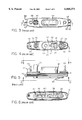
- FIGS. 10 and 11 are perspective views showing alternative embodiments of a liquid containment and dispensing device according to the present invention.
- FIGS. 12 and 13 are fragmentary perspective views showing further alternative embodiments of a liquid containment and dispensing device according to the present invention.
- FIG. 1 An ink containment and dispensing device in accordance with an embodiment of the invention described in the aforesaid U.S. patent application Ser. No. 08/429,987 is identified in FIG. 1 by reference numeral 10.
- the device 10 has a hard protective shell 12 which contains a flexible pouch 14 for containing ink.
- the shell 12 is attached to a chassis 16, which houses a pump 18 and a fluid outlet 20.
- a protective cap 22 is attached to the chassis 16 and a label 24 is glued to the outside of the shell 12 and cap 22 elements of the device 10 to secure the shell 12, chassis 16, and cap 22 firmly together.
- the cap 22 is provided with apertures which allow access to the pump and the fluid outlet.
- the device 10 is adapted to be removably inserted into a docking bay (not shown) within an ink-jet printer.
- a fluid inlet in the docking bay is adapted to engage the fluid outlet 20 to allow ink flow from the device 10 to the printer.
- An actuator (not shown) in the docking bay is adapted to engage the pump 18. Operation of the actuator causes the pump 18 to provide ink in a series of small doses of a predetermined volume from the flexible pouch 14, through the fluid outlet 20, to the fluid inlet of the docking bay and then to the printer.
- the chassis 16 is provided with a fill port 32 at one end and an exhaust port 34 at the other end. Ink can be added to the ink supply through the fill port 32 while air displaced by the added ink is exhausted through the exhaust port 34. After the ink supply is filled, the fill port 32 is sealed with a ball 35 press fit into the fill port 32.
- a pumping chamber 36 having an open bottom is formed on the bottom of the chassis 16 within a rigid perimetrical wall 37, which is preferably formed integrally with the chassis 16. As described in more detail below, the chamber 36 can be pressured to supply ink to the printer without pressurizing the interior of the pouch 14.
- the top of the chamber 36 is provided with an inlet port 38 through which ink may enter the chamber 36 from the pouch 14 by gravity and/or by a negative pressure within the chamber 36.
- An outlet port 40 through which ink may be expelled from the chamber 36 is also provided.
- a one-way flapper valve 42 located at the bottom of the inlet port 38 serves to limit the return of ink from the chamber 36 to the pouch 14.
- the flapper valve 42 is a rectangular piece of flexible material. In the illustrated embodiment the valve 42 is positioned over the bottom of the inlet port 38 and is heat staked to the chassis 16 at the midpoints of its short sides. When the pressure within the chamber 36 drops below that in the pouch 14, the unstaked sides of the valve 42 each flex to allow the flow of ink through the inlet port 38 and into the chamber 36.
- valve 42 By heat staking the valve 42 to the chassis 16 along an opposed pair of sides, less flexing of the valve 42 is required or permitted than would be the case if the valve 42 were staked only along a single side, thereby ensuring that it closes more securely, and this effect is enhanced by doing the heat staking at the midpoints of the shorter sides, as opposed to the longer sides.
- the flapper valve 42 is made of a two ply material.
- the outer ply is a layer of low density polyethylene 0.0015 inches thick.
- the inner ply is a layer of polyethylene terephthalate (PET) 0.0005 inches thick.
- PET polyethylene terephthalate
- the illustrated flapper valve 42 is approximately 5.5 millimeters wide and 8.7 millimeters long. Such a material is impervious to the flow of ink therethrough when the valve 42 is in its closed position.
- the bottom of the chamber 36 is covered with a flexible diaphragm 44.
- the diaphragm 44 is slightly larger than the opening at the bottom of the chamber and is sealed around the free edge of the perimetrical wall 37 that defines the chamber 36.
- the excess material in the oversized diaphragm 44 allows the diaphragm to flex up and down to vary the volume of the chamber 36.
- the displacement of the diaphragm 44 allows the volume of the chamber 36 to be varied by about 0.7 cubic centimeters.
- the fully expanded volume of the illustrated chamber 36 is between about 2.2 and 2.5 cubic centimeters.
- the diaphragm 44 is made of a multi-ply material having a layer of low density polyethylene 0.0005 inches thick, a layer of adhesive, a layer of metallized polyethylene terephthalate (PET) 0.00048 inches thick, a layer of adhesive, and a layer of low density polyethylene 0.0005 inches thick.
- PET metallized polyethylene terephthalate
- other suitable materials may also be used to form the diaphragm 44.
- the diaphragm 44 in the illustrated embodiment is heat staked, using conventional methods, to the free edge of the wall 37 of the chamber 36. During the heat staking process, the low density polyethylene in the diaphragm will seal any folds or wrinkles in the diaphragm 44.
- the diaphragm 44 thus, is impervious to the transmission of oxygen and moisture therethrough, thereby safeguarding the ink in the chamber 36 from degradation by exposure to any such substance.
- a pressure plate 46 is positioned adjacent the diaphragm 44, the pressure plate 46 serving as a piston with respect to the chamber 36.
- a pump spring 48 made of stainless steel in the illustrated embodiment, biases the pressure plate 46 against the diaphragm 44 to urge the diaphragm outward so as to expand the size of the chamber 36.
- One end of the pump spring 48 is received on a spike 50 formed on the top of the chamber 36 and the other end of the pump spring 48 is received on a spike 52 formed on the pressure plate 46 in order to retain the pump spring 48 in position.
- the pressure plate 46 in the illustrated embodiment is molded of high density polyethylene.
- a hollow cylindrical boss 54 extends downward from the chassis 16 to form the housing of the fluid outlet 20, the boss 54 being formed integrally with the chassis 16.
- a bore 56 of the hollow boss 54 has a narrow throat 54a at its lower end.
- a sealing ball 58 made of stainless steel in the illustrated embodiment, is positioned within the bore 56.
- the sealing ball 58 is sized such that it can move freely within the bore 56, but cannot pass through the narrow throat portion 54a thereof.
- a sealing spring 60 is positioned within the bore 56 to urge the sealing ball 58 against the narrow throat 54a to form a seal and prevent the flow of ink through the fluid outlet.
- a retaining ball 62 made of stainless steel in the illustrated embodiment, is press fit into the top of the bore to retain the sealing spring 60 in place.
- the bore 56 is configured to allow the free flow of ink past the retaining ball 62 and into the bore 56.
- a raised manifold 64 is formed on the top of the chassis 16.
- the manifold 64 forms a cylindrical boss around the top of the fill port 32 and a similar boss around the top of the inlet port 38 so that each of these ports is isolated.
- the manifold 64 extends around the base of the fluid outlet 20 and the outlet port 40 to form an open-topped conduit 66 joining the two outlets.
- the flexible ink pouch 14 is attached to the top of the manifold 64 so as to form a top cover for the conduit 66. In the illustrated embodiment, this is accomplished by heat staking a rectangular plastic sheet 68 to the top surface of the manifold 64 to enclose the conduit 66.
- the chassis 16 molded of high density polyethylene and the plastic sheet is low density polyethylene that is 0.002 inches thick. These two materials can be easily heat staked to one another using conventional methods and are also readily recyclable.
- the sheet 68 After the plastic sheet 68 is attached to the chassis 16, the sheet is folded and sealed around its two sides and top to form the flexible ink pouch 14. Again, in the illustrated embodiment, heat staking can be used to seal the perimeter of the flexible pouch 14. The plastic sheet over the fill port 32 and over the inlet port 38 can be punctured, pierced, or otherwise removed so as not to block the flow of ink through these ports.
- the flexible pouch 14 provides an ideal way to contain ink, it may be easily punctured or ruptured and allows a relatively high amount of water loss from the ink. Accordingly, to protect the pouch 14 and to limit water loss, the pouch 14 is enclosed within the protective shell 12.
- the shell 12 is made of clarified polypropylene, which is sufficiently translucent to permit inspection of the ink within the pouch 14 to determine that an adequate volume of ink remains for proper operation of the printer. A thickness of about one millimeter has been found to provide robust protection and to prevent unacceptable water loss from the ink. However, the material and thickness of the shell may vary in other embodiments.
- the top of the shell 12 has a number of raised ribs 70 to facilitate gripping of the shell 12 as it is inserted in or withdrawn from the docking bay.
- a vertical rib 72 projects laterally from each side of the shell 12. The vertical rib 72 can be received within a slot (not shown) in the docking bay to provide lateral support and stability to the ink supply when it is positioned within the printer.
- the bottom of the shell 12 is provided with two circumferential grooves or recesses 76 which engage two circumferential ribs or beads 78 formed on a depending perimetrical wall 79 of the chassis 16 to attach the shell 12 to the chassis 16 in a snap fit.
- the attachment between the shell 12 and the chassis 16 should, preferably, be snug enough to prevent accidental separation of the chassis from the shell and to resist the flow of ink from the shell should the flexible reservoir develop a leak.
- the ingress of air should be limited, however, in order to maintain a high humidity within the shell and minimize water loss from the ink.
- ink can be injected through the fill port 32.
- the flexible pouch 14 expands so as to substantially fill the shell 12.
- the sealing ball 58 can be depressed to open the fluid outlet and a partial vacuum can be applied to the fluid outlet 20.
- the partial vacuum at the fluid outlet causes ink from the pouch 14 to fill the chamber 36, the conduit 66, and the bore of the cylindrical boss 54 such that little, if any, air remains in contact with the ink.
- the partial vacuum applied to the fluid outlet also speeds the filling process.
- an exhaust port 34 is provided to allow the escape of air from the shell as the reservoir expands. Once the ink supply is filled, a ball 35 is press fit into the fill port 32 to prevent the escape of ink or the entry of air.
- any gas trapped within the device during the filling process will be carbon dioxide, not air. This may be preferable because carbon dioxide may dissolve in some inks while air may not. In general, it is preferable to remove as much gas from the device as possible so that bubbles and the like do not enter the print head or the trailing tube.
- the protective cap 22 is placed on the device 10 after the reservoir is filled.
- the protective cap is provided with a groove 80 which receives a rib 82 on the chassis to attach the cap to the chassis.
- the cap 22 carries a plug 84 which plugs the exhaust port 34 to limit the flow of air into the chassis and reduce water loss from the ink.
- a stud 86 extends from each end of the chassis 16 and is received within an aperture in the cap 22 to aid in aligning the cap and to strengthen the union between the cap and the chassis.
- the free ends of the studs 86, which extend beyond the apertures of the cap 22, are preferably deformed after the cap 22 is in place, for example, by contacting them with a heated tool, to provide a tamper resistant attachment of the cap 22 to the chassis 16.
- the label 24 is glued to the sides of the device 10 to hold the shell 12, chassis 16, and cap 22 firmly together.
- a hot-melt pressure sensitive or other adhesive is used to adhere the label in a manner that prevents the label from being peeled off and inhibits tampering with the ink supply.
- the cap 22 in the illustrated embodiment is provided with a vertical rib 90 protruding from each side.
- the rib 90 is an extension of the vertical rib 72 on the shell and is received within the slot provided in the docking bay in a manner similar to the vertical rib 72.
- the cap 22 has protruding keys 92 located on each side of the rib 90.
- One or more of the keys 92 can be optionally deleted or altered so as to provide a unique identification of the particular ink supply by color or type.
- Mating keys (not shown), identifying a particular type or color of ink supply can be formed in the docking bay. In this manner, a user cannot inadvertently insert an ink supply of the wrong type or color into a docking bay.
- This arrangement is particularly advantageous for a multi-color printer where there are adjacent docking bays for ink supplies of various colors.
- elements that correspond to the elements of the embodiment of FIGS. 1-9 are identified by a 100 series numeral, the last two digits of which correspond to the two digits of the corresponding element of the embodiment of FIGS. 1-9.
- the end of the shell 112 that is away from the end that is closed by the cap 122 is the end that is at the top of the device 110 when the device 110 is properly oriented to be inserted in a docking bay of an associated ink-jet printer (not shown).
- the shell is provided with an opposed pair of outwardly projecting tabs 112a, 112b along the shorter pair of its sides.
- the tabs 112a, 112b serve to assist such a person in grasping a device 110 for insertion of a device 110 in a printer or for the removal of an empty device 110 from the printer, and naturally indicate the proper orientation of the device 110 at the time of its insertion into the printer.
- the shell 112 of the device 110 may be relatively inexpensively molded from a suitable thermoplastic material in a mold of simple design.
- elements corresponding to the elements of the embodiment of FIGS. 1-9 are identified by a 200 series numeral, the last two digits which are the digits of the corresponding element of the invention of FIGS. 1-9.
- the ink containment and dispensing device of FIG. 11 is generally identified by reference numeral 210, and except as hereinafter described, corresponds to the device 10 of FIGS. 1-9.
- the device 210 has a hard protective shell 212 that is open at one end and the open end of the shell 212 is closed by a protective cap 222.
- the end of the shell 212 that is away from the end that is closed by the cap 222 is the end that is at the top of the device 210 when the device 210 is ready for insertion in a docking bay of an associated ink-jet printer (not shown).
- the shell 212 is provided with an opposed pair of longitudinally extending, outwardly projecting ribs 212a, 212b along the shorter pair of its sides.
- the shell 212 is also provided with a spaced apart plurality of transversely extending ribs 212c, 212d, 212e, 212f that intersect the longitudinally extending rib 212a; likewise the shell 212 is provided with a spaced apart plurality of transversely extending ribs 212g, 212h, 212i, 212j that intersect the longitudinally extending rib 212b.
- the ribs 212a, 212b serve to very positively assist a person grasping a device 210 for insertion of the device 210 into a printer, or for removal of an empty device 210 from the printer, and naturally indicate the proper orientation of the device 210 at the time of its insertion into the printer.
- the shell 212 of the device 210 may be manufactured in its illustrated complex configuration from a suitable thermoplastic material by molding.
- elements corresponding to the elements of FIGS. 1-9 are identified by a 300 series numeral, the last two digits of which are the two digits of the corresponding element of the invention of FIGS. 1-9.
- the ink containment and dispensing device of FIG. 12 is generally identified by reference numeral 310 and, except as hereinafter described, corresponds to the device 10 of FIGS. 1-9.
- the device 310 has a hard protective shell 312 that is open at one end, and the open end of the shell 312 is closed by a protective cap 322.
- a label 324 is glued to the sides of the device 310 to hold the shell 312 and cap 322 firmly together.
- a hot-melt pressure sensitive or other adhesive is used to adhere the label 324 to the shell 312 and the cap 322 in a manner that prevents the label from being peeled off and inhibits tampering with the ink supply.
- the shell 312 has an opposed pair of shorter sides interspersed with an opposed pair of longer sides and each of its shorter sides tapers inwardly near the closed end of the shell 312, as is illustrated at 312a, to provide a gripping surface for the fingers of a user involved in installing the device 310 in a printer. Further, the shell 312 is provided with a radially outwardly projecting flange 312b above the level of the tapered portion 312a to further assist a user in grasping the device 310 at the tapered portion 312a and an opposed tapered portion, not shown.
- Each of the opposed shorter sides of the shell 312 is also provided with an outwardly projecting flange, for example the flange 312c, below the level of the tapered portion 312a.
- the purpose of the flange 312c is to inhibit insertion of the device 310 into the docking bay of a printer in an inverted orientation of the device 310.
- Each of the opposed shorter sides of the shell 312 is also provided with an outwardly projecting and longitudinally extending rib 312d.
- the purpose of the rib 312d is to assist in the insertion of the device 310 into the docking bay of a printer, and the rib 312d is provided with an eccentrically positioned notch 312e to positively lock the device 310 into the docking bay of the printer.
- the shell 312 may be manufactured in its illustrated, complex configuration from a suitable thermoplastic material by molding.
- elements corresponding to the elements of FIGS. 1-9 are identified by a 400 series numeral, the last two digits of which are the two digits of the corresponding element of the invention of FIGS. 1-9.
- the ink containment and dispensing device of FIG. 13 is generally identified by reference numeral 410 and, except as hereinafter described, corresponds to the device 10 of FIGS. 1-9.
- the device 410 has a hard protective shell 412, which is open at one end, and the open end of the shell 412 is closed by a protective cap 422.
- the shell 412 has an opposed pair of shorter sides interspersed with an opposed pair of longer sides, and each of the shorter sides has an inwardly tapered finger gripping portion near the upper end thereof, in the illustrated orientation of the device 410, the inwardly tapered portion illustrated in FIG. 13 being identified by reference numeral 412a.
- the inwardly tapered portions of the shell 412, including the portion 412a, provide a location to be gripped by the fingers of the person installing the device 410 into, or removing the device 410 from, a docking bay of an ink-jet printer.
- Each of the opposed shorter sides of the shell 412 of the device 410 is further provided with an outwardly projecting tab above the level of the tapered portion, such as the tab 412b which is positioned above the tapered portion 412a of the shell 412.
- Each of the tabs, such as the tab 412b is concave in an upwardly facing direction and serves to prevent the device 410 from being inserted into the docking bay of a printer in an inverted orientation.
- the shell 412 of the device 410 may be manufactured in its illustrated complex configuration from a suitable thermoplastic material by molding.
- liquid containment and dispensing device of the various embodiments of the present invention has been specifically described as a device for containing and dispensing a supply of printing ink in an ink-jet printer as the preferred embodiment of the invention.
- present invention can easily be adapted to the containment and dispensing of other Newtonian (low viscosity) liquids.
Abstract
Description
Claims (7)
Priority Applications (16)
| Application Number | Priority Date | Filing Date | Title |
|---|---|---|---|
| US08/934,564 US6068371A (en) | 1997-09-22 | 1997-09-22 | Liquid containment and dispensing device with improved position indicating indicia |
| CA002247033A CA2247033C (en) | 1997-09-22 | 1998-09-14 | Liquid containment and dispensing device with improved position indicating indicia |
| SG1998003662A SG72863A1 (en) | 1997-09-22 | 1998-09-15 | Liquid containment and dispensing device with improved position indicating indicia |
| KR1019980038406A KR19990029889A (en) | 1997-09-22 | 1998-09-17 | Liquid storage and dispensing device with position mark recognition |
| DK98117752T DK0903236T3 (en) | 1997-09-22 | 1998-09-18 | Liquid containing and dispensing device |
| DE69835126T DE69835126T2 (en) | 1997-09-22 | 1998-09-18 | Liquid container and dispenser |
| ES98117752T ES2270487T3 (en) | 1997-09-22 | 1998-09-18 | LIQUID CONTAINER AND DISPENSING DEVICE. |
| PT98117752T PT903236E (en) | 1997-09-22 | 1998-09-18 | Liquid containment and dispensing device |
| EP98117752A EP0903236B1 (en) | 1997-09-22 | 1998-09-18 | Liquid containment and dispensing device |
| AT98117752T ATE332236T1 (en) | 1997-09-22 | 1998-09-18 | LIQUID CONTAINER AND DISPENSING DEVICE |
| CN98120613A CN1215664A (en) | 1997-09-22 | 1998-09-21 | Liquid containment and dispensing device |
| BR9803942-3A BR9803942A (en) | 1997-09-22 | 1998-09-21 | Containment and liquid dispensing device with improved position indicative signs |
| IDP981272A ID21410A (en) | 1997-09-22 | 1998-09-21 | FLUID CHARGING AND DISTRIBUTION TOOLS WITH A PERFECT POSITION SHOWING INDEX |
| JP10268703A JPH11157095A (en) | 1997-09-22 | 1998-09-22 | Liquid housing dispenser with improved position display mark |
| TW087115760A TW404894B (en) | 1997-09-22 | 1998-09-22 | Liquid containment and dispensing device with improved position indicating indicia |
| CY20061101401T CY1107520T1 (en) | 1997-09-22 | 2006-09-27 | FLUID CONTAINING AND PROVIDING DEVICE |
Applications Claiming Priority (1)
| Application Number | Priority Date | Filing Date | Title |
|---|---|---|---|
| US08/934,564 US6068371A (en) | 1997-09-22 | 1997-09-22 | Liquid containment and dispensing device with improved position indicating indicia |
Publications (1)
| Publication Number | Publication Date |
|---|---|
| US6068371A true US6068371A (en) | 2000-05-30 |
Family
ID=25465733
Family Applications (1)
| Application Number | Title | Priority Date | Filing Date |
|---|---|---|---|
| US08/934,564 Expired - Lifetime US6068371A (en) | 1997-09-22 | 1997-09-22 | Liquid containment and dispensing device with improved position indicating indicia |
Country Status (16)
| Country | Link |
|---|---|
| US (1) | US6068371A (en) |
| EP (1) | EP0903236B1 (en) |
| JP (1) | JPH11157095A (en) |
| KR (1) | KR19990029889A (en) |
| CN (1) | CN1215664A (en) |
| AT (1) | ATE332236T1 (en) |
| BR (1) | BR9803942A (en) |
| CA (1) | CA2247033C (en) |
| CY (1) | CY1107520T1 (en) |
| DE (1) | DE69835126T2 (en) |
| DK (1) | DK0903236T3 (en) |
| ES (1) | ES2270487T3 (en) |
| ID (1) | ID21410A (en) |
| PT (1) | PT903236E (en) |
| SG (1) | SG72863A1 (en) |
| TW (1) | TW404894B (en) |
Cited By (8)
| Publication number | Priority date | Publication date | Assignee | Title |
|---|---|---|---|---|
| US6827431B2 (en) * | 2001-05-10 | 2004-12-07 | Canon Kabushiki Kaisha | Ink tank |
| US20070077101A1 (en) * | 2005-09-30 | 2007-04-05 | Kyocera Mita Corporation | Toner container and image forming apparatus |
| CN1318218C (en) * | 2002-06-28 | 2007-05-30 | 奥西-技术有限公司 | Ink container |
| US20080165232A1 (en) * | 2007-01-10 | 2008-07-10 | Kenneth Yuen | Ink cartridge |
| US20120249693A1 (en) * | 2011-03-30 | 2012-10-04 | Brother Kogyo Kabushiki Kaisha | Ink cartridge |
| US8602541B2 (en) | 2011-03-30 | 2013-12-10 | Brother Kogyo Kabushiki Kaisha | Ink cartridge |
| US9448095B2 (en) | 2012-03-19 | 2016-09-20 | David S. Smith America, Inc. | Volume metering dispenser |
| USD942537S1 (en) * | 2019-06-07 | 2022-02-01 | Canon Kabushiki Kaisha | Ink tank for printer |
Families Citing this family (15)
| Publication number | Priority date | Publication date | Assignee | Title |
|---|---|---|---|---|
| JP4141523B2 (en) | 1997-03-19 | 2008-08-27 | セイコーエプソン株式会社 | Ink supply flow path valve device |
| DE69938202T3 (en) | 1998-07-15 | 2013-06-13 | Seiko Epson Corp. | An ink supply system |
| JP2001063090A (en) * | 1999-04-27 | 2001-03-13 | Canon Inc | Ink tank, valve unit used in the ink tank, manufacture of the ink tank, ink-jet head cartridge with the ink tank and ink-jet recording apparatus |
| JP3697137B2 (en) * | 2000-03-31 | 2005-09-21 | キヤノン株式会社 | Liquid jet recording apparatus, liquid jet head unit, and mounting method thereof |
| ATE398023T1 (en) | 2000-10-20 | 2008-07-15 | Seiko Epson Corp | INK CARTRIDGE FOR INKJET RECORDING DEVICE |
| EP1481808B1 (en) | 2000-10-20 | 2006-12-13 | Seiko Epson Corporation | Ink cartridge |
| US7018014B2 (en) | 2000-12-28 | 2006-03-28 | Xerox Corporation | Printing brand sensing bypass using an emulator |
| DE60227966D1 (en) * | 2001-09-25 | 2008-09-11 | Bridgestone Corp | RESIN COMPOSITION CONTAINING ARTICLES |
| JP3991853B2 (en) | 2002-09-12 | 2007-10-17 | セイコーエプソン株式会社 | ink cartridge |
| JP4165278B2 (en) | 2003-04-09 | 2008-10-15 | ブラザー工業株式会社 | Ink jet recording apparatus and ink cartridge |
| JP4529369B2 (en) | 2003-04-16 | 2010-08-25 | ブラザー工業株式会社 | Inkjet recording device |
| CN100595070C (en) * | 2007-04-26 | 2010-03-24 | 珠海格力新技术研究所有限公司 | Ink ribbon cartridge for ink-jet printer |
| US8240816B2 (en) * | 2009-12-21 | 2012-08-14 | Eastman Kodak Company | Ink fill port for inkjet ink tank |
| US8317300B2 (en) | 2010-03-31 | 2012-11-27 | Eastman Kodak Company | Inkjet printer |
| US8313180B2 (en) * | 2010-03-31 | 2012-11-20 | Eastman Kodak Company | Inkjet ink tank |
Citations (6)
| Publication number | Priority date | Publication date | Assignee | Title |
|---|---|---|---|---|
| US4568954A (en) * | 1984-12-06 | 1986-02-04 | Tektronix, Inc. | Ink cartridge manufacturing method and apparatus |
| US5136305A (en) * | 1990-12-06 | 1992-08-04 | Xerox Corporation | Ink jet printer with ink supply monitoring means |
| EP0623471A2 (en) * | 1993-05-03 | 1994-11-09 | Hewlett-Packard Company | Method and device for preventing unintended use of print cartridges |
| EP0741038A2 (en) * | 1995-04-27 | 1996-11-06 | Owens-Illinois Closure Inc. | Liquid containment and dispensing device |
| EP0778148A1 (en) * | 1995-12-04 | 1997-06-11 | Hewlett-Packard Company | Keying system for ink supply containers |
| US5691755A (en) * | 1994-04-18 | 1997-11-25 | Hewlett-Packard Company | Collapsible ink cartridge |
Family Cites Families (5)
| Publication number | Priority date | Publication date | Assignee | Title |
|---|---|---|---|---|
| US5467118A (en) * | 1993-12-21 | 1995-11-14 | Hewlett-Packard Company | Ink cartridge for a hard copy printing or plotting apparatus |
| US5646665A (en) * | 1993-04-30 | 1997-07-08 | Hewlett-Packard Company | Side biased datum scheme for inkjet cartridge and carriage |
| US5408746A (en) * | 1993-04-30 | 1995-04-25 | Hewlett-Packard Company | Datum formation for improved alignment of multiple nozzle members in a printer |
| US5825387A (en) * | 1995-04-27 | 1998-10-20 | Hewlett-Packard Company | Ink supply for an ink-jet printer |
| EP0816098B1 (en) * | 1996-06-27 | 2002-09-18 | Hewlett-Packard Company, A Delaware Corporation | Keying system for ink supply containers |
-
1997
- 1997-09-22 US US08/934,564 patent/US6068371A/en not_active Expired - Lifetime
-
1998
- 1998-09-14 CA CA002247033A patent/CA2247033C/en not_active Expired - Fee Related
- 1998-09-15 SG SG1998003662A patent/SG72863A1/en unknown
- 1998-09-17 KR KR1019980038406A patent/KR19990029889A/en not_active Application Discontinuation
- 1998-09-18 EP EP98117752A patent/EP0903236B1/en not_active Expired - Lifetime
- 1998-09-18 DK DK98117752T patent/DK0903236T3/en active
- 1998-09-18 PT PT98117752T patent/PT903236E/en unknown
- 1998-09-18 AT AT98117752T patent/ATE332236T1/en active
- 1998-09-18 DE DE69835126T patent/DE69835126T2/en not_active Expired - Lifetime
- 1998-09-18 ES ES98117752T patent/ES2270487T3/en not_active Expired - Lifetime
- 1998-09-21 CN CN98120613A patent/CN1215664A/en active Pending
- 1998-09-21 ID IDP981272A patent/ID21410A/en unknown
- 1998-09-21 BR BR9803942-3A patent/BR9803942A/en not_active IP Right Cessation
- 1998-09-22 JP JP10268703A patent/JPH11157095A/en active Pending
- 1998-09-22 TW TW087115760A patent/TW404894B/en not_active IP Right Cessation
-
2006
- 2006-09-27 CY CY20061101401T patent/CY1107520T1/en unknown
Patent Citations (7)
| Publication number | Priority date | Publication date | Assignee | Title |
|---|---|---|---|---|
| US4568954A (en) * | 1984-12-06 | 1986-02-04 | Tektronix, Inc. | Ink cartridge manufacturing method and apparatus |
| US5136305A (en) * | 1990-12-06 | 1992-08-04 | Xerox Corporation | Ink jet printer with ink supply monitoring means |
| EP0623471A2 (en) * | 1993-05-03 | 1994-11-09 | Hewlett-Packard Company | Method and device for preventing unintended use of print cartridges |
| US5519422A (en) * | 1993-05-03 | 1996-05-21 | Hewlett-Packard Company | Method and device for preventing unintended use of print cartridges |
| US5691755A (en) * | 1994-04-18 | 1997-11-25 | Hewlett-Packard Company | Collapsible ink cartridge |
| EP0741038A2 (en) * | 1995-04-27 | 1996-11-06 | Owens-Illinois Closure Inc. | Liquid containment and dispensing device |
| EP0778148A1 (en) * | 1995-12-04 | 1997-06-11 | Hewlett-Packard Company | Keying system for ink supply containers |
Cited By (10)
| Publication number | Priority date | Publication date | Assignee | Title |
|---|---|---|---|---|
| US6827431B2 (en) * | 2001-05-10 | 2004-12-07 | Canon Kabushiki Kaisha | Ink tank |
| CN1318218C (en) * | 2002-06-28 | 2007-05-30 | 奥西-技术有限公司 | Ink container |
| US20070077101A1 (en) * | 2005-09-30 | 2007-04-05 | Kyocera Mita Corporation | Toner container and image forming apparatus |
| US7613416B2 (en) | 2005-09-30 | 2009-11-03 | Kyocera Mita Corporation | Toner container with grippable recesses and image forming apparatus having such a toner container |
| US20080165232A1 (en) * | 2007-01-10 | 2008-07-10 | Kenneth Yuen | Ink cartridge |
| US20120249693A1 (en) * | 2011-03-30 | 2012-10-04 | Brother Kogyo Kabushiki Kaisha | Ink cartridge |
| US8602541B2 (en) | 2011-03-30 | 2013-12-10 | Brother Kogyo Kabushiki Kaisha | Ink cartridge |
| US8876268B2 (en) * | 2011-03-30 | 2014-11-04 | Brother Kogyo Kabushiki Kaisha | Ink cartridge |
| US9448095B2 (en) | 2012-03-19 | 2016-09-20 | David S. Smith America, Inc. | Volume metering dispenser |
| USD942537S1 (en) * | 2019-06-07 | 2022-02-01 | Canon Kabushiki Kaisha | Ink tank for printer |
Also Published As
| Publication number | Publication date |
|---|---|
| EP0903236A3 (en) | 2000-08-23 |
| TW404894B (en) | 2000-09-11 |
| ATE332236T1 (en) | 2006-07-15 |
| DE69835126T2 (en) | 2007-02-15 |
| EP0903236B1 (en) | 2006-07-05 |
| PT903236E (en) | 2006-11-30 |
| CA2247033C (en) | 2004-08-24 |
| EP0903236A2 (en) | 1999-03-24 |
| ID21410A (en) | 1999-06-10 |
| CN1215664A (en) | 1999-05-05 |
| BR9803942A (en) | 1999-12-21 |
| CY1107520T1 (en) | 2013-03-13 |
| KR19990029889A (en) | 1999-04-26 |
| JPH11157095A (en) | 1999-06-15 |
| DK0903236T3 (en) | 2006-10-30 |
| CA2247033A1 (en) | 1999-03-22 |
| DE69835126D1 (en) | 2006-08-17 |
| SG72863A1 (en) | 2000-05-23 |
| ES2270487T3 (en) | 2007-04-01 |
Similar Documents
| Publication | Publication Date | Title |
|---|---|---|
| US6068371A (en) | Liquid containment and dispensing device with improved position indicating indicia | |
| US5784087A (en) | Liquid containment and dispensing device | |
| US5856840A (en) | Method of manufacturing a replaceable ink supply for an ink-jet printer | |
| US7114801B2 (en) | Method and apparatus for providing ink to an ink jet printing system | |
| US6764169B2 (en) | Method and apparatus for providing ink to an ink jet printing system | |
| JP3014333B2 (en) | Refill kit and method for refilling ink supply mechanism for ink jet printer | |
| EP0891867B1 (en) | Liquid containment and dispensing device with improved resistance to shock loads | |
| US5900895A (en) | Method for refilling an ink supply for an ink-jet printer | |
| US6692117B1 (en) | Liquid containment and dispensing device with improved flow control valve | |
| EP0870618A2 (en) | Liquid containment and dispensing device | |
| MXPA98005557A (en) | Containment device and liquid assortment with better flow control valve | |
| MXPA98002829A (en) | Device to contain and assure liquids, improved connection of the bag containing liquidosal basti | |
| MXPA98005556A (en) | Containment device and assortment of liquid with improved resistance to the impa loads |
Legal Events
| Date | Code | Title | Description |
|---|---|---|---|
| AS | Assignment |
Owner name: OWENS-ILLINOIS CLOSURE INC., OHIO Free format text: ASSIGNMENT OF ASSIGNORS INTEREST;ASSIGNORS:HMELAR, SUSAN M.;CONTAXIS, WILLIAM III;REEL/FRAME:008814/0501;SIGNING DATES FROM 19970623 TO 19970707 Owner name: HEWLETT-PACKARD COMPANY, OREGON Free format text: ASSIGNMENT OF ASSIGNORS INTEREST;ASSIGNORS:HMELAR, SUSAN M.;CONTAXIS, WILLIAM III;REEL/FRAME:008814/0501;SIGNING DATES FROM 19970623 TO 19970707 |
|
| AS | Assignment |
Owner name: HEWLETT-PACKARD COMPANY, OREGON Free format text: ASSIGNMENT OF ASSIGNORS INTEREST;ASSIGNOR:WALLACE, J. KENNETH;REEL/FRAME:009126/0911 Effective date: 19980402 Owner name: OWENS-ILLINOIS CLOSURE INC., OHIO Free format text: ASSIGNMENT OF ASSIGNORS INTEREST;ASSIGNOR:WALLACE, J. KENNETH;REEL/FRAME:009126/0911 Effective date: 19980402 |
|
| STCF | Information on status: patent grant |
Free format text: PATENTED CASE |
|
| CC | Certificate of correction | ||
| FPAY | Fee payment |
Year of fee payment: 4 |
|
| FPAY | Fee payment |
Year of fee payment: 8 |
|
| AS | Assignment |
Owner name: HEWLETT-PACKARD DEVELOPMENT COMPANY, L.P., TEXAS Free format text: ASSIGNMENT OF ASSIGNORS INTEREST;ASSIGNOR:OWENS-ILLINOIS CLOSURE INC.;REEL/FRAME:020098/0357 Effective date: 20070726 |
|
| FPAY | Fee payment |
Year of fee payment: 12 |