US6071249A - Method and apparatus for obtaining blood for diagnostic tests - Google Patents
Method and apparatus for obtaining blood for diagnostic tests Download PDFInfo
- Publication number
- US6071249A US6071249A US08/982,324 US98232497A US6071249A US 6071249 A US6071249 A US 6071249A US 98232497 A US98232497 A US 98232497A US 6071249 A US6071249 A US 6071249A
- Authority
- US
- United States
- Prior art keywords
- nosepiece
- blood
- opening
- skin
- vacuum
- Prior art date
- Legal status (The legal status is an assumption and is not a legal conclusion. Google has not performed a legal analysis and makes no representation as to the accuracy of the status listed.)
- Expired - Lifetime
Links
Images


Classifications
-
- A—HUMAN NECESSITIES
- A61—MEDICAL OR VETERINARY SCIENCE; HYGIENE
- A61B—DIAGNOSIS; SURGERY; IDENTIFICATION
- A61B5/00—Measuring for diagnostic purposes; Identification of persons
- A61B5/15—Devices for taking samples of blood
- A61B5/151—Devices specially adapted for taking samples of capillary blood, e.g. by lancets, needles or blades
- A61B5/15186—Devices loaded with a single lancet, i.e. a single lancet with or without a casing is loaded into a reusable drive device and then discarded after use; drive devices reloadable for multiple use
-
- A—HUMAN NECESSITIES
- A61—MEDICAL OR VETERINARY SCIENCE; HYGIENE
- A61B—DIAGNOSIS; SURGERY; IDENTIFICATION
- A61B5/00—Measuring for diagnostic purposes; Identification of persons
- A61B5/145—Measuring characteristics of blood in vivo, e.g. gas concentration, pH value; Measuring characteristics of body fluids or tissues, e.g. interstitial fluid, cerebral tissue
- A61B5/14532—Measuring characteristics of blood in vivo, e.g. gas concentration, pH value; Measuring characteristics of body fluids or tissues, e.g. interstitial fluid, cerebral tissue for measuring glucose, e.g. by tissue impedance measurement
-
- A—HUMAN NECESSITIES
- A61—MEDICAL OR VETERINARY SCIENCE; HYGIENE
- A61B—DIAGNOSIS; SURGERY; IDENTIFICATION
- A61B5/00—Measuring for diagnostic purposes; Identification of persons
- A61B5/145—Measuring characteristics of blood in vivo, e.g. gas concentration, pH value; Measuring characteristics of body fluids or tissues, e.g. interstitial fluid, cerebral tissue
- A61B5/1486—Measuring characteristics of blood in vivo, e.g. gas concentration, pH value; Measuring characteristics of body fluids or tissues, e.g. interstitial fluid, cerebral tissue using enzyme electrodes, e.g. with immobilised oxidase
-
- A—HUMAN NECESSITIES
- A61—MEDICAL OR VETERINARY SCIENCE; HYGIENE
- A61B—DIAGNOSIS; SURGERY; IDENTIFICATION
- A61B5/00—Measuring for diagnostic purposes; Identification of persons
- A61B5/15—Devices for taking samples of blood
- A61B5/150007—Details
- A61B5/150015—Source of blood
- A61B5/150022—Source of blood for capillary blood or interstitial fluid
-
- A—HUMAN NECESSITIES
- A61—MEDICAL OR VETERINARY SCIENCE; HYGIENE
- A61B—DIAGNOSIS; SURGERY; IDENTIFICATION
- A61B5/00—Measuring for diagnostic purposes; Identification of persons
- A61B5/15—Devices for taking samples of blood
- A61B5/150007—Details
- A61B5/150053—Details for enhanced collection of blood or interstitial fluid at the sample site, e.g. by applying compression, heat, vibration, ultrasound, suction or vacuum to tissue; for reduction of pain or discomfort; Skin piercing elements, e.g. blades, needles, lancets or canulas, with adjustable piercing speed
- A61B5/150061—Means for enhancing collection
- A61B5/150068—Means for enhancing collection by tissue compression, e.g. with specially designed surface of device contacting the skin area to be pierced
-
- A—HUMAN NECESSITIES
- A61—MEDICAL OR VETERINARY SCIENCE; HYGIENE
- A61B—DIAGNOSIS; SURGERY; IDENTIFICATION
- A61B5/00—Measuring for diagnostic purposes; Identification of persons
- A61B5/15—Devices for taking samples of blood
- A61B5/150007—Details
- A61B5/150053—Details for enhanced collection of blood or interstitial fluid at the sample site, e.g. by applying compression, heat, vibration, ultrasound, suction or vacuum to tissue; for reduction of pain or discomfort; Skin piercing elements, e.g. blades, needles, lancets or canulas, with adjustable piercing speed
- A61B5/150061—Means for enhancing collection
- A61B5/150076—Means for enhancing collection by heating
-
- A—HUMAN NECESSITIES
- A61—MEDICAL OR VETERINARY SCIENCE; HYGIENE
- A61B—DIAGNOSIS; SURGERY; IDENTIFICATION
- A61B5/00—Measuring for diagnostic purposes; Identification of persons
- A61B5/15—Devices for taking samples of blood
- A61B5/150007—Details
- A61B5/150053—Details for enhanced collection of blood or interstitial fluid at the sample site, e.g. by applying compression, heat, vibration, ultrasound, suction or vacuum to tissue; for reduction of pain or discomfort; Skin piercing elements, e.g. blades, needles, lancets or canulas, with adjustable piercing speed
- A61B5/150061—Means for enhancing collection
- A61B5/150099—Means for enhancing collection by negative pressure, other than vacuum extraction into a syringe by pulling on the piston rod or into pre-evacuated tubes
-
- A—HUMAN NECESSITIES
- A61—MEDICAL OR VETERINARY SCIENCE; HYGIENE
- A61B—DIAGNOSIS; SURGERY; IDENTIFICATION
- A61B5/00—Measuring for diagnostic purposes; Identification of persons
- A61B5/15—Devices for taking samples of blood
- A61B5/150007—Details
- A61B5/150206—Construction or design features not otherwise provided for; manufacturing or production; packages; sterilisation of piercing element, piercing device or sampling device
- A61B5/150221—Valves
-
- A—HUMAN NECESSITIES
- A61—MEDICAL OR VETERINARY SCIENCE; HYGIENE
- A61B—DIAGNOSIS; SURGERY; IDENTIFICATION
- A61B5/00—Measuring for diagnostic purposes; Identification of persons
- A61B5/15—Devices for taking samples of blood
- A61B5/150007—Details
- A61B5/150374—Details of piercing elements or protective means for preventing accidental injuries by such piercing elements
- A61B5/150381—Design of piercing elements
- A61B5/150412—Pointed piercing elements, e.g. needles, lancets for piercing the skin
-
- A—HUMAN NECESSITIES
- A61—MEDICAL OR VETERINARY SCIENCE; HYGIENE
- A61B—DIAGNOSIS; SURGERY; IDENTIFICATION
- A61B5/00—Measuring for diagnostic purposes; Identification of persons
- A61B5/15—Devices for taking samples of blood
- A61B5/150007—Details
- A61B5/150374—Details of piercing elements or protective means for preventing accidental injuries by such piercing elements
- A61B5/150381—Design of piercing elements
- A61B5/150503—Single-ended needles
-
- A—HUMAN NECESSITIES
- A61—MEDICAL OR VETERINARY SCIENCE; HYGIENE
- A61B—DIAGNOSIS; SURGERY; IDENTIFICATION
- A61B5/00—Measuring for diagnostic purposes; Identification of persons
- A61B5/15—Devices for taking samples of blood
- A61B5/150007—Details
- A61B5/150374—Details of piercing elements or protective means for preventing accidental injuries by such piercing elements
- A61B5/150534—Design of protective means for piercing elements for preventing accidental needle sticks, e.g. shields, caps, protectors, axially extensible sleeves, pivotable protective sleeves
- A61B5/150664—Pivotable protective sleeves, i.e. sleeves connected to, or integrated in, the piercing or driving device, and which are pivoted for covering or uncovering the piercing element
-
- A—HUMAN NECESSITIES
- A61—MEDICAL OR VETERINARY SCIENCE; HYGIENE
- A61B—DIAGNOSIS; SURGERY; IDENTIFICATION
- A61B5/00—Measuring for diagnostic purposes; Identification of persons
- A61B5/15—Devices for taking samples of blood
- A61B5/151—Devices specially adapted for taking samples of capillary blood, e.g. by lancets, needles or blades
- A61B5/15101—Details
- A61B5/15103—Piercing procedure
- A61B5/15107—Piercing being assisted by a triggering mechanism
- A61B5/15113—Manually triggered, i.e. the triggering requires a deliberate action by the user such as pressing a drive button
-
- A—HUMAN NECESSITIES
- A61—MEDICAL OR VETERINARY SCIENCE; HYGIENE
- A61B—DIAGNOSIS; SURGERY; IDENTIFICATION
- A61B5/00—Measuring for diagnostic purposes; Identification of persons
- A61B5/15—Devices for taking samples of blood
- A61B5/151—Devices specially adapted for taking samples of capillary blood, e.g. by lancets, needles or blades
- A61B5/15101—Details
- A61B5/15115—Driving means for propelling the piercing element to pierce the skin, e.g. comprising mechanisms based on shape memory alloys, magnetism, solenoids, piezoelectric effect, biased elements, resilient elements, vacuum or compressed fluids
- A61B5/15125—Driving means for propelling the piercing element to pierce the skin, e.g. comprising mechanisms based on shape memory alloys, magnetism, solenoids, piezoelectric effect, biased elements, resilient elements, vacuum or compressed fluids comprising a vacuum or compressed fluids
-
- A—HUMAN NECESSITIES
- A61—MEDICAL OR VETERINARY SCIENCE; HYGIENE
- A61B—DIAGNOSIS; SURGERY; IDENTIFICATION
- A61B5/00—Measuring for diagnostic purposes; Identification of persons
- A61B5/15—Devices for taking samples of blood
- A61B5/151—Devices specially adapted for taking samples of capillary blood, e.g. by lancets, needles or blades
- A61B5/15186—Devices loaded with a single lancet, i.e. a single lancet with or without a casing is loaded into a reusable drive device and then discarded after use; drive devices reloadable for multiple use
- A61B5/15188—Constructional features of reusable driving devices
- A61B5/1519—Constructional features of reusable driving devices comprising driving means, e.g. a spring, for propelling the piercing unit
-
- A—HUMAN NECESSITIES
- A61—MEDICAL OR VETERINARY SCIENCE; HYGIENE
- A61B—DIAGNOSIS; SURGERY; IDENTIFICATION
- A61B5/00—Measuring for diagnostic purposes; Identification of persons
- A61B5/15—Devices for taking samples of blood
- A61B5/151—Devices specially adapted for taking samples of capillary blood, e.g. by lancets, needles or blades
- A61B5/15186—Devices loaded with a single lancet, i.e. a single lancet with or without a casing is loaded into a reusable drive device and then discarded after use; drive devices reloadable for multiple use
- A61B5/15188—Constructional features of reusable driving devices
- A61B5/15192—Constructional features of reusable driving devices comprising driving means, e.g. a spring, for retracting the lancet unit into the driving device housing
- A61B5/15194—Constructional features of reusable driving devices comprising driving means, e.g. a spring, for retracting the lancet unit into the driving device housing fully automatically retracted, i.e. the retraction does not require a deliberate action by the user, e.g. by terminating the contact with the patient's skin
-
- A—HUMAN NECESSITIES
- A61—MEDICAL OR VETERINARY SCIENCE; HYGIENE
- A61B—DIAGNOSIS; SURGERY; IDENTIFICATION
- A61B5/00—Measuring for diagnostic purposes; Identification of persons
- A61B5/15—Devices for taking samples of blood
- A61B5/157—Devices characterised by integrated means for measuring characteristics of blood
-
- A—HUMAN NECESSITIES
- A61—MEDICAL OR VETERINARY SCIENCE; HYGIENE
- A61B—DIAGNOSIS; SURGERY; IDENTIFICATION
- A61B5/00—Measuring for diagnostic purposes; Identification of persons
- A61B5/41—Detecting, measuring or recording for evaluating the immune or lymphatic systems
- A61B5/411—Detecting or monitoring allergy or intolerance reactions to an allergenic agent or substance
-
- A—HUMAN NECESSITIES
- A61—MEDICAL OR VETERINARY SCIENCE; HYGIENE
- A61B—DIAGNOSIS; SURGERY; IDENTIFICATION
- A61B2562/00—Details of sensors; Constructional details of sensor housings or probes; Accessories for sensors
- A61B2562/02—Details of sensors specially adapted for in-vivo measurements
- A61B2562/0295—Strip shaped analyte sensors for apparatus classified in A61B5/145 or A61B5/157
-
- A—HUMAN NECESSITIES
- A61—MEDICAL OR VETERINARY SCIENCE; HYGIENE
- A61B—DIAGNOSIS; SURGERY; IDENTIFICATION
- A61B5/00—Measuring for diagnostic purposes; Identification of persons
- A61B5/15—Devices for taking samples of blood
- A61B5/150007—Details
- A61B5/150358—Strips for collecting blood, e.g. absorbent
Definitions
- This application relates to three patent applications, METHOD AND APPARATUS FOR OBTAINING BLOOD FOR DIAGNOSTIC TESTS, Attorney's Docket No. 6005.US.P1, METHOD AND APPARATUS FOR OBTAINING BLOOD FOR DIAGNOSTIC TESTS, Attorney's Docket No. 6005.US.P2, METHOD AND APPARATUS FOR OBTAINING BLOOD FOR DIAGNOSTIC TESTS, Attorney's Docket No. 6005.US.P4, filed on evendate herewith
- the specifications, drawings, and claims of these applications are incorporated herein by reference. All of the foregoing applications are commonly owned by the assignee of this invention.
- This invention relates to a method and apparatus for obtaining samples of blood for diagnostic purposes.
- diabetes The prevalence of diabetes has been increasing markedly in the world. At this time, diagnosed diabetics represented about 3% of the population of the United States. It is believed that the total actual number of diabetics in the United States is over 16,000,000. Diabetes can lead to numerous complications, such as, for example, retinopathy, nephropathy, and neuropathy.
- the most important factor for reducing diabetes-associated complications is the maintenance of an appropriate level of glucose in the blood stream.
- the maintenance of the appropriate level of glucose in the blood stream may prevent and even reverse many of the effects of diabetes.
- Glucose monitoring devices of the prior art have operated on the principle of taking blood from an individual by a variety of methods, such as by needle or lancet. An individual then coats a paper strip carrying chemistry with the blood, and finally insert the blood-coated strip into a blood glucose meter for measurement of glucose concentration by determination of change in reflectance.
- the medical apparatus of the prior art for monitoring the level of glucose in the blood stream required that an individual have separately available a needle or lancet for extracting blood from the individual, strips carrying blood chemistry for creating a chemical reaction with respect to the glucose in the blood stream and changing color, and a blood glucose meter for reading the change in color indicating the level of glucose in the blood stream.
- the level of blood glucose when measured by a glucose meter, is read from a strip carrying the blood chemistry through the well-known process of reading reflectometers for glucose oxidation.
- lancets comprise a blade and a pressable end opposed thereto, with the blade having an acute end capable of being thrust into skin of a human. By striking the pressable portion, the acute end of the blade will pierce the skin, for example, of the finger.
- the finger lancet is primarily used to obtain small volumes of blood, i.e., less than 1 mL. Diabetics use the finger lancet to obtain volumes of blood less than 25 ⁇ L for analysis for glucose. A small amount of blood for the blood test will ooze out of the skin. There are many small blood vessels in each finger so that a finger can be squeezed to cause a larger drop of blood to ooze.
- the finger is one of the most sensitive parts of the body; accordingly, the finger lancet leads to even more pain than what would be experienced by extracting blood via lancet at a different body site.
- the finger lancet presents another problem because of the limited area available on the fingers for lancing. Because it is recommended that diabetics monitor their blood glucose levels four to six times per day, the limited area on the fingers calls for repeated lancing of areas that are already sore. Because fingers are sensitive to pain, it is a recent tendency that the arm is subjected to blood sampling. See, for example, U.S. Pat. No. 4,653,513. The device of U.S. Pat. No.
- 4,653,513 comprises a cylindrical housing and a lancet support, which has a gasket or flexible portion slidably accommodated in the housing. Springs will retract the lancet support to thereby reduce air pressure in the housing so that it sucks a blood sample, automatically and immediately after a lancet pierces the skin. See also U.S. Pat. No.
- 5,320,607 which discloses a device comprising a sealed vacuum chamber in a state of preexisting reduced pressure, a support member for the sealed vacuum chamber, the support member defining a suction portion adjacent the sealed vacuum chamber, the suction portion, in cooperation with the sealed vacuum chamber, exposing an area of the skin of a patient to a reduced pressure state when the device is actuated, and means arranged within the suction portion for slightly rupturing a portion of the area of skin of the patient exposed to the reduced pressure state.
- the blood volume requirements for a standard glucose test strip is typically 3 ⁇ L or more, an area of the body that can generate that much blood from a lancet wound must be used. It is believed, however, that improvements in glucose test strip technology will reduce the volume of blood needed to 1 to 3 ⁇ L. Because the finger is well supplied with blood and the amount of blood can be increased by squeezing the finger after lancing, the finger is the currently preferred body site for lancing, even though lancing of the finger is painful.
- a less painful technique for obtaining body fluids could be found if a reliable method were found for lancing a body part that is less sensitive to pain than the finger and obtaining a useful amount of blood from that body part.
- a body part such as the forearm is much less sensitive to pain than the finger, but the amount of blood resulting from the lancing procedure is generally of an inadequate volume for use with current detection technology.
- Ways of increasing blood flow to the finger are common knowledge. The recommendation is made to diabetics to run their finger under hot water prior to lancing to improve the blood flow in the finger and the amount of blood collected from the finger. Running hot water over a body part to improve blood flow is impractical for areas such as the forearm or thigh. The availability of hot water is also a concern.
- This invention provides a method and apparatus for extracting a sample of blood from a patient for subsequent diagnostic tests, e.g., glucose monitoring.
- the method comprises the steps of:
- step (a) is preceded by the step of increasing the availability of blood in the portion of the skin from which the sample is to be extracted.
- the availability of blood in the portion of the skin from which the sample is to be extracted can be increased by means of a vacuum, which is applied to the surface of the skin in the vicinity of the opening prior to forming the opening in the skin.
- the vacuum causes the portion of the skin in the vicinity of the blood extraction site to become engorged with blood.
- the vacuum also causes the portion of the skin in the vicinity of the blood extraction site to become stretched.
- An opening in this stretched portion of skin can be formed with a cutting or puncturing device, e.g., a lancet, or other device capable of forming an opening in the skin, e.g., a laser or a fluid jet. If a cutting or puncturing device is used to form the opening, it must be retracted from the opening prior to the step of extracting the sample of blood from the opening. This retraction will allow the unrestricted flow of blood through the opening. After the opening is formed, a vacuum is used to aid in extracting the sample of blood from the opening in the skin. The sample can be analyzed from the drops of blood that collect on the surface of the skin at the site of the opening by applying the blood directly to a glucose detector.
- a cutting or puncturing device e.g., a lancet, or other device capable of forming an opening in the skin, e.g., a laser or a fluid jet.
- the sample be collected in such a manner, e.g., via a capillary tube, that it can be analyzed by conventional diagnostic devices, such as, for example, a biosensor.
- the sample can be collected in a collection zone that is integrated with a conventional diagnostic device, e.g., a biosensor.
- the availability of blood in the area of the skin from which the sample is to be extracted can be increased by means of applying thermal energy to that area of skin.
- the thermal energy causes the blood in that area of the skin to flow more rapidly, thereby allowing more blood to be collected per given unit of time.
- steps (a) and (b) can be carried out in the same manner as they were carried out in the aforementioned preferred embodiment.
- an apparatus for collecting a sample of body fluid for analysis in a diagnostic test e.g., blood
- a diagnostic test e.g., blood
- the apparatus comprises:
- a device for forming an unobstructed opening in an area of skin from which said sample is to be extracted preferably a lancing assembly
- the housing is preferred for the convenience of the patient and the protection of the components.
- the vacuum pump requires a source of power. If the apparatus includes a housing, the source of power can be disposed within the housing. Alternatively, the source of power can be external to the housing.
- the preferred device for forming an unobstructed opening in the area of the skin from which the sample of blood is to be extracted is a lancing assembly, which comprises a lancet for forming an opening in the skin.
- the unobstructed opening in the skin can be formed by a laser or a fluid jet.
- the vacuum pump can serve the dual purposes of (1) stretching the skin and (2) enhancing the extraction of the sample of blood from the unobstructed opening in the skin.
- the vacuum pump can serve the triple purposes of (1) stretching the skin, (2) increasing the availability of blood to the area of the skin from which the sample is to be extracted, and (3) enhancing the extraction of the sample of blood from the unobstructed opening in the skin.
- the housing further contains electronics having programmed instructions to switch the vacuum pump on and off to maintain the desired level of vacuum.
- the apparatus preferably contains valves, such as, for example, solenoid valves, for triggering the lancet of the lancing assembly and releasing the vacuum at the conclusion of the blood extraction procedure.
- the apparatus can optionally contain a heating element to increase the availability of blood to the area of the skin from which the sample is to be extracted.
- the apparatus can also contain a glucose detector integrated with the apparatus, e.g., a biosensor, to analyze the sample of blood collected by the apparatus.
- the method and apparatus of this invention provide several advantages over the methods and apparatus of the prior art.
- FIG. 1 is a plan view of the components of a preferred embodiment of the apparatus of this invention. In this Figure, the cover of the housing is removed.
- FIG. 2 is a schematic diagram illustrating how a vacuum causes a portion of the skin to become stretched prior to the formation of an opening in the skin from which the sample of blood is extracted.
- FIG. 2 also illustrates the spatial relationship between the nosepiece of lancing assembly and a glucose detector, e.g., a biosensor.
- FIG. 3 is a block diagram illustrating the electronics of the preferred embodiment.
- FIG. 4 is a schematic diagram illustrating an alternative seal for the vacuum of the device of the present invention.
- FIG. 5 is a perspective view of an embodiment of the apparatus of this invention. In this figure, the housing of the apparatus is open.
- FIG. 6 is a perspective view of an embodiment of the apparatus of this invention. In this figure, the housing of the apparatus is open.
- FIG. 7 is a perspective view of an embodiment of the apparatus of this invention. In this figure, the housing of the apparatus is open.
- FIG. 8 is a perspective view of an embodiment of the apparatus of this invention. In this figure, the housing of the apparatus is open.
- FIG. 9 is a perspective view of an embodiment of the apparatus of this invention. In this figure, the housing of the apparatus is open.
- FIG. 10 is a perspective view of an embodiment of the apparatus of this invention. In this figure, the housing of the apparatus is open.
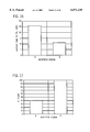
- FIG. 11 is an elevational view of a cross section of a preferred embodiment of a nosepiece of this invention.
- FIG. 12 is a series of elevational views of cross sections of various embodiments of nosepieces suitable for use in this invention.
- FIGS. 13A, 13B, 13C, and 13D are schematic diagrams of the positioning of the nosepiece of the apparatus of this invention relative to the lancing assembly, the detection element, and the skin prior to application of vacuum, during application of vacuum, during lancing, and during blood collection and analysis, respectively.
- FIG. 14 is a series of elevational views of cross sections of various embodiments of nosepieces suitable for use in this invention.
- FIG. 15 is a graph illustrating the effect that various embodiments of nosepieces have on filling time of a detecting element.
- FIG. 16 is a graph illustrating the average time to fill a multiple-layer element as a function of the nosepiece used.
- FIG. 17 is a graph illustrating the percent filled, as a function of the nosepiece used.
- FIG. 18 is a series of elevational views of cross sections and top plan views of various embodiments of nosepieces suitable for use in this invention
- FIG. 19 is a graph illustrating airflow rate as a function of the nosepiece used.
- FIG. 20 is a graph illustrating the average volume of blood collected as a function of the material used to make the seal of the nosepiece assembly.
- FIG. 21A is an elevational view of a cross section of a preferred embodiment of a nosepiece of this invention, wherein the seal is in a first position.
- FIG. 21B is an elevational view of the nosepiece of FIG. 21A, wherein the seal is in a second position.
- the embodiments of this invention require the following steps to carry out the function of obtaining a sample of blood for carrying out a diagnostic test, e.g., glucose monitoring:
- the step of forming an unobstructed opening in the area of the skin from which the sample of blood is to be extracted is carried out by a piercing device or some other type of device capable of forming an unobstructed opening in the skin.
- Piercing devices suitable for this invention include, but are not limited to, mechanical lancing assemblies.
- Other type of device capable of forming an unobstructed opening in the skin include, but are not limited to, lasers and fluid jets.
- Other types of devices capable of forming an unobstructed opening in the skin can be used, and this disclosure should not be construed so as to be limited to the devices listed.
- Mechanical lancing assemblies are well-known in the art. These assemblies comprise include standard steel lancets, serrated devices, and multiple tip devices. The lancets can be made from metal or plastic. Multiple tip devices provide redundancy, which can reduce the number of failures and increase the volume of blood extracted.
- Lasers suitable for forming an unobstructed opening in the skin to draw blood are also well-known in the art. See for example, U.S. Pat. Nos. 4,775,361, 5,165,418, 5,374,556, International Publication Number WO 94/09713, and Lane et al. (1984) IBM Research Report--"Ultraviolet-Laser Ablation of Skin", all of which are incorporated herein by reference.
- Lasers that are suitable for forming an unobstructed opening in the skin the skin include Er:YAG, Nd:YAG, and semiconductor lasers.
- Fluid jets suitable for forming an unobstructed opening in the skin employ a high pressure jet of fluid, preferably a saline solution, to penetrate the skin.
- the opening formed by the device must be unobstructed.
- unobstructed means free from clogging, hampering, blocking, or closing up by an obstacle. More specifically, the expressions "unobstructed opening in the area of the skin from which the sample is to be extracted”, “unobstructed opening in the skin”, and the like are intended to mean that the portion of the opening below the surface of the skin is free from any foreign object that would clog, hamper, block, or close up the opening, such as, for example, a needle of any type.
- a lancet For example, if a lancet is used to form the opening, it must be retracted from the opening prior to the commencement of the extraction of blood. Because lasers and fluid jets do not require contact with the skin to form openings in the skin, these types of devices typically provide unobstructed openings. However, these expressions are rot intended to include foreign objects at the surface of the skin or above the surface of the skin, such as, for example, a glucose monitor. This feature, i.e., the unobstructed opening, can be contrasted with the opening used in the method and apparatus described in U.S. Pat. No. 5,320,607, in which the piercing and cutting means remains in the skin during the duration of the period of blood extraction.
- Extraction enhancing elements suitable for use in this invention include, but are not limited to, vacuum, skin stretching elements, and heating elements. It has seen discovered that when these elements are used in combination, the volume of blood extracted is greatly increased, particularly when a vacuum is applied in combination with skin stretching. In this combination, the vacuum not only causes the blood to be rapidly removed from the unobstructed opening by suction, it also causes a portion of the skin in the vicinity of the opening to be stretched. Stretching of the skin can be effected by other means, such as mechanical means or adhesives. Mechanical means include devices for pinching or pulling the skin; adhesives bring about stretching of the skin by means of pulling. It is preferred to use a vacuum to effect stretching of the skin. Like a vacuum, a heating element operates more effectively in combination with other techniques, e.g., stretching of the skin.
- step (a), the step of forming the unobstructed opening is preceded by the step of increasing the availability of blood at the area of the skin from which the sample is to be extracted.
- the availability of blood at a given area of the skin can be increased by at least two methods.
- a vacuum can be used to cause blood flowing through blood vessels to pool in the area of the skin where the vacuum is applied.
- heat can be used to cause blood flowing through blood vessels to flow more rapidly in the area of the skin where heat is applied, thereby allowing a greater quantity of blood to be extracted from the blood extraction site per unit of time.
- Elements for increasing the availability of blood at a blood extraction site that are suitable for use in this invention include, but are not limited to, vacuum, localized heating element, skin stretching element, and chemicals.
- applying a vacuum to the area of the skin from which blood is to be extracted can increase blood availability under and within the skin at the application site.
- the vacuum can also be used to stretch the skin upwardly into a chamber, thereby increasing pooling of blood under and within the skin.
- This combination of vacuum and skin stretching can be an extension of the combination used to extract blood from the opening in the skin, as previously described. It is well-known that heat can increase perfusion on the large scale of a limb or a finger. Chemical means, such as histamine, can be used to cause a physiological response to increase perfusion under and within the skin.
- the extracted blood is also collected.
- the step of collecting the sample of blood can be carried out in a variety of ways.
- the blood can be collected in capillary tubes or absorbent paper.
- the blood can be allowed to remain in the lancet assembly, from which it can used directly in a diagnostic test.
- the sample of blood is collected on the application zone of a glucose detector, from where it can be used directly to provide an indication of the concentration of glucose in the blood.
- the sample can be analyzed at a time later than the time of collection or at a location remote from the location of collection or both.
- Blood extraction device 10 comprises a housing 12. Disposed within the housing 12 are a vacuum pump 14, a lancing assembly 16, a battery 18, and electronics 20. A switch 22 is provided to activate electronics 20.
- the housing 12 is preferably made from a plastic material. It is preferably of sufficient size to contain all of the components that are required for forming an unobstructed opening in the area of the skin from which the sample of blood is to be extracted, extracting the sample of blood from the unobstructed opening in the skin, preferably with the aid of a vacuum and a stretching of the skin, and collecting the extracted sample in an amount sufficient to carry out a diagnostic test. Methods of preparing the housing 12 are well-known to one of ordinary skill in the art. As stated previously, the housing 12 is not required, but is preferred for the convenience of the patient and the protection of the components.
- the vacuum pump 14 must be capable of providing a vacuum that will provide sufficient suction to stretch the portion of the skin in the region from which the sample of blood is to be extracted.
- the portion of stretched skin is raised a distance of 1 to 10 mm, preferably 3 to 5 mm, from the plane of the body part of which it is a portion.
- the suction provided by the vacuum pump 14 is stretching the appropriate portion of skin, the suction provided by the vacuum pump 14 also causes the stretched portion to become engorged with blood.
- the level of suction provided must be sufficient to cause a relatively large volume of blood to become engorged at the point that the vacuum is applied.
- the vacuum pump 14 must also be capable of providing sufficient suction to extract blood from the opening in the skin at a rate sufficient to extract at least 1 ⁇ L of blood within a period of five minutes.
- a vacuum pump 14 that is suitable for the device of this invention can be a diaphragm pump, a piston pump, a rotary vane pump, or any other pump that will perform the required functions set forth previously.
- the vacuum pump 14 employs a self-contained permanent magnet DC motor.
- Vacuum pumps that are suitable for this invention are well-known to those of ordinary skill in the art and are commercially available.
- a vacuum pump suitable for use in the present invention is available from T-Squared Manufacturing Company, Nutley, N.J., and has the part number T2-03.08.004.
- the vacuum pump 14 is preferably capable of providing a pressure of down to about -14.7 psig, and is more preferably operated at from about -3.0 psig to about -10.0 psig.
- the area of the skin subjected to vacuum preferably ranges up to about 50 cm 2 , more preferably from about 0.1 to about 5.0 cm 2 .
- the period of vacuum application prior to forming the opening in the skin i.e., for increasing the availability of blood to the application site, preferably ranges up to about 5 minutes, preferably from about 1 to about 15 seconds.
- the period of vacuum application subsequent to forming the opening in the skin i.e., for aiding in the extraction of blood from the unobstructed opening, preferably ranges up to about 5 minutes, preferably from about 1 to about 60 seconds.
- the vacuum provided by the vacuum pump 14 can be continuous or pulsed. A continuous vacuum is preferred for the reason that it requires fewer components than does a pulsed vacuum. It is preferred that the vacuum applied not cause irreversible damage to the skin. It is preferred that the vacuum applied not produce bruises and discolorations of the skin that persist for several days. It is also preferred that the level of vacuum applied and duration of application of vacuum not be so excessive that it causes the dermis to separate from the epidermis, which results in the formation of a blister filled with fluid.
- the vacuum pump feature offers significant advantages over the method and apparatus described in U.S. Pat. No. 5,320,607, in which a sealed vacuum chamber in a state of preexisting reduced pressure is used.
- the use of a vacuum pump provides the user with greater control of blood extraction conditions than does a sealed vacuum chamber in a state of preexisting reduced pressure. For example, if the vacuum is insufficient, energy can be provided to the vacuum pump to bring about a higher level of vacuum, thereby providing greater suction.
- the lancing assembly 16 comprises at least one lancet.
- Standard lancets can be used in the lancing assembly of this invention.
- Narrow gauge (28 to 30 gauge) lancets are preferred.
- Lancets suitable for this invention can be made from metal or plastic. Lancets suitable for this invention can have single points or multiple points.
- the depth of penetration of the lancet preferably ranges from about 0.4 to about 2.5 mm, more preferably from about -0.4 to about 1.6 mm.
- the length of the lancet or lancets preferably ranges from about 1 mm to about 5 mm.
- the lancing assembly is preferably located so that the user can easily replace used lancets.
- the lancet of the lancing assembly 16 can be cocked manually or automatically, e.g., by means of a vacuum-actuated piston or diaphragm.
- the lancet of the lancing assembly 16 can be triggered by manually or automatically, e.g., by means of a vacuum-actuated piston or diaphragm.
- Lancing assemblies are well-known in the art. Representative examples of lancing assemblies suitable for this invention are described in U.S. Pat. Nos. Re. 32,922, 4,203,446, 4,990,154, and 5,487,748, all of which are incorporated herein by reference. A particularly suitable lancing assembly for this invention is described in U.S. Pat. No. Re. 32,922. However, any lancing assembly selected should operate in conjunction with the other features of the apparatus of this invention. For example, if a vacuum is employed, the lancing assembly must be designed so that a vacuum can be formed and drawn through the assembly. The lancing assembly can be designed to allow automatic cocking and automatic triggering of the lancet.
- the vacuum pump 14 is connected to the lancing assembly 16 by an evacuation tube 24.
- the air that is evacuated from the lancing assembly 16 by the vacuum pump 14 is removed via the evacuation tube 24.
- the evacuation tube 24 is typically made from a polymeric material.
- a check valve 20 is placed between the vacuum pump 14 and the lancing assembly 16 at a point in the evacuation tube 24 to prevent air removed from the lancing assembly 16 by the vacuum pump 14 from flowing back to the lancing assembly 16 and adversely affecting the vacuum.
- a source of power for the vacuum pump 14 can be disposed within the housing 12.
- a source of power suitable for the device of this invention is a battery 18.
- an external source of power can be used to operate the vacuum pump 14.
- the power source is actuated by the electronics 20, which, in turn, is actuated by the switch 22.
- the electronics 20 may incorporate a microprocessor or microcontroller.
- the function of the electronics 20 is to switch power on and off to operate the various components in the apparatus. These components include, but are not limited to, the vacuum pump 14.
- the electronics 20 can also be use to switch power on and off to operate components in alternative embodiments, e.g., heating elements, lancets, indicating devices, and valves.
- Electronics suitable for this invention is the "TATTLETALE MODEL 5F" controller/data logger, commercially available from Onset Computer Corporation, 536 MacArthur Blvd. P.O. Box 3450, Pocasset, Mass. 02559-3450.
- Auxiliary electronic devices such as power transistors, pressure monitors, and OP-Amps (operational amplifiers), may also be required in order to provide an interface between the controller and the operational components. All electronics required for this invention are well-known to one of ordinary skill in the art and are commercially available. Auxiliary electronic devices suitable for use in this invention include the following components:
- FIG. 3 illustrates by way of a block diagram how the foregoing electronic components can be arranged to carry out the method of the present invention.
- the nosepiece 30 of the lancing assembly 16 is applied to the surface of the skin, designated herein by the letter "S".
- the end of the nosepiece 30 that contacts the skin is equipped with a seal 32.
- the purpose of the seal 32 is to prevent air from leaking into blood extraction chamber 34, so that the vacuum pump 14 can provide sufficient suction action for increasing the availability of blood to the area of the skin from which the sample is to be extracted, stretching the skin, and extracting the sample of blood from the unobstructed opening in the skin.
- the seal 32 surrounds an opening 33 in the nosepiece 30.
- the opening 33 in the nosepiece allows communication between the surface of the skin and a blood extraction chamber 34 in the nosepiece 30.
- the seal 32 is preferably made of a rubber or an elastomeric material.
- FIG. 4 illustrates an alternative position for the seal 32.
- the seal is designated by the reference numeral 32'.
- the remaining parts of FIG. 4 are the same as those of FIG. 2, and, accordingly, retain the same reference numerals as were used in FIG. 2.
- FIG. 2 it is shown that the interior walls of the nosepiece form a shape that is essentially cylindrical. While this design is capable of providing adequate performance in the method of this invention, it has been discovered that by changing the construction of the interior cavity of the nosepiece, collection of blood can be accelerated.
- the nosepiece assembly 3000 comprises a nosepiece 3001 and a seal 3002.
- the nosepiece 3001 comprises a lower base 3004 having an opening 3005 therein.
- Above the lower base 3004 is an upper base 3006 having an opening 3007 therein.
- the features of the exterior of the nosepiece, other than the lower base 3004 and the upper base 3006, are not critical to this invention, and one of ordinary skill in the art can design the exterior walls of the nosepiece in any manner that does not adversely affect the operation of the nosepiece of this invention.
- the features of the interior of the nosepiece, the lower base 3004, the upper base 3006, and, in some cases, the seal 3002 are critical and, consequently, they will be described in greater detail.
- An interior wall 3008 encloses a cavity 3010 of the nosepiece 3001. It is critical that the interior wall 3008 of the nosepiece 3001 be structured in such a manner that the opening 3007 in the upper base 3006 be of an equal or smaller area than the opening 3005 in the lower base 3004. It is desired that the area of the opening 3007 be reduced to as small of a size as possible, but not so small as to interfere with the collection of blood by a glucose monitor (see FIG. 2) or with the path of a lancet.
- An optional rim 3012 can surround the opening 3007 in the upper base 3006.
- the interior wall 3008 can be tapered so as to bring about a reduction in the area of the opening 3007.
- the tapering can begin at any point along the interior wall 3008 of the nosepiece 3001. If the tapered portion runs all the way from the beginning of the tapered portion to the upper base 3006, the optional rim 3012 still have a depth of zero, and thus be eliminated from the nosepiece.
- the area of the opening 3007 can merely be made smaller than the area of the opening 3005, such as through the use of step-wise cylindrical sections.
- Ports 3014 and 3016 can be included in the nosepiece 3001 to give the cavity 3010 more exposure to a vacuum, if needed.
- the optional rim 3012 has a depth designated by the line "ab”. This depth typically ranges from 0 to about 1.5 mm, preferably from 0 to about 1.0 mm.
- the opening 3007 in the upper base 3006 has a major dimension designated by the line "cd”. The area of the opening 3007 typically ranges from about 1 to about 500 mm 2 , preferably from about 1 to about 150 mm 2 .
- the opening 3005 in the lower base 3004 has a major dimension designated by the line "ef".
- the area of the opening 3005 typically ranges from about 10 to about 500 mm 2 , preferably from about 50 to about 150 mm 2 .
- the distance from the lowermost point of the rim 3012 to to lowermost point of the seal 3002 (hereinafter “rim-to-seal distance") is designated by the line “bg”. This distance typically ranges from about 1.5 to about 8.0 mm, preferably from about 3 to about 6 mm. It is preferred that the distance be selected so that the skin, when stretched into the nosepiece 3001, comes as close as possible to the rim 3012 or the upper base 3006 of the nosepiece 3001. If the rim 3012 is not present, the point "d" will be located at the level of the upper base 3006.
- the thickness of the seal 3002 is represented by the line “eh”.
- the width of the sealing surface and the width of the sealed surface of the lower base 3004 are designated by the line “hj".
- This improved nosepiece has several advantages.
- the improved design and construction of the nosepiece can provide enhanced collection of blood from the unobstructed opening in the skin.
- the nosepiece brings about a better seal to the body than do the nosepieces previously used. A better seal reduces the amount of vacuum leakage, with the result that a less expensive vacuum pump can be used.
- the improved nosepiece allows a seal to be maintained on those individuals having excessively hairy skin.
- the switch 22 is actuated, typically by being pressed, thereby activating the electronics 20, which starts the vacuum pump 14.
- the vacuum pump 14 then provides a suction action.
- the suction action of the vacuum pump 14 causes the skin circumscribed by the seal 32 to become engorged with blood. Engorgement of the skin with blood is accompanied by a stretching of and rising up of the skin up to opening 33.
- the lancing assembly 16 is triggered, thereby causing the lancet 36 to penetrate the skin that has risen up to the opening 33 and that is engorged with blood.
- the lancet 36 is preferably triggered automatically, by a solenoid valve 38 that causes a vacuum-actuateed piston (not shown) to trigger the lancet 36.
- the lancet 36 is then retracted, preferably automatically. Thereupon, the blood flows out of the unobstructed opening resulting from the lancet 36, and, aided by the vacuum generated by the vacuum pump 14, is collected.
- the electronics 20 causes the vacuum pump 14 to stop.
- the device 10 can then be removed from the surface of the skin after another solenoid valve (not shown because it is hidden under solenoid valve 38) is opened to vent the vacuum to allow ease of removal of the device from the surface of the skin.
- Solenoid valves suitable for use with the apparatus described herein are commercially available from The Lee Company, Essex, Conn., and have the part number LHDA0511111H.
- the blood is preferably directly collected on the application zone of a glucose detector, e.g., a reflectance strip or biosensor.
- the blood can then be used as the sample for a determination of glucose concentration in blood.
- the blood can be collected by other collection devices, such as, for example, a capillary tube or absorbent paper.
- the apparatus of the present invention can include a glucose detector for analyzing the blood sample extracted by the apparatus.
- Glucose detectors are well-known in the art. With respect to glucose monitoring, there are two major categories of glucose detectors--reflectometers and biosensors. Representative examples of reflectometers suitable for this invention are described in U.S. Pat. No. 4,627,445, incorporated herein by reference. Representative examples of biosensors suitable for this invention are described in U.S. Pat. No. 5,509,410, incorporated herein by reference.
- the glucose detector is preferably disposed in the nosepiece 30 of the lancing assembly 16.
- the glucose detector must be located at a position sufficiently close to the site of blood extraction so that the quantity of extracted blood collected will be sufficient to carry out a standard glucose monitoring test. Typically, this distance will preferably be no more than 5 mm from the site of blood extraction, more preferably no more than 3 mm from the site of blood extraction, most preferably no more than 1 mm from the site of blood extraction. Care must be taken in the placement of the glucose detector so that the detector does not adversely affect the vacuum, when a vacuum is employed to aid in the extraction of blood.
- the glucose detector 40 should be modified, if necessary, so that the blood collected in the collection zone of the glucose detector is capable of being used to activate the glucose detector.
- FIG. 2 also illustrates a manner for disposing a glucose detector 40 in the nosepiece 30 of the lancing assembly 16.
- FIGS. 5, 6, 7, 8, 9, and 10 illustrate various alternative embodiments of the apparatus of this invention.
- blood extraction device 100 comprises a housing 102.
- the housing 102 is separable into two portions, a receiving portion 102a and a projecting portion 102b.
- a gasket 104 is provided to seal the portions 102a and 102b of the housing 102 and to aid in separation of the receiving portion 102a from the projecting portion 102b.
- the receiving portion 102a forms a tight fit with the projecting portion 102b by means of friction.
- Projecting elements 102c and 102d are used to guide the projecting portion 102b into the receiving portion 102a.
- a vacuum pump (not shown), a lancing assembly 108, a battery (not shown), and electronics (not shown).
- a switch 109 is provided to activate the electronics.
- the vacuum pump is connected to the lancing assembly 108 by an evacuation tube (not shown).
- a check valve (not shown) is placed between the vacuum pump and the lancing assembly 108.
- the receiving portion 102a and the projecting portion 102b are fitted tightly together.
- the area of the receiving portion 102a of the housing 102 of the device 100 that is to contact the skin is equipped with a seal 110.
- the seal 110 surrounds an opening 112 in the receiving portion 102a.
- the opening 112 in the receiving portion 102a allows communication between the surface of the skin and a blood extraction chamber adjacent to a glucose detector 114, shown here in the shape of a strip.
- the device 100 is positioned so that the lancing assembly 108 is placed over the region on the surface of the skin from which the sample is to be obtained.
- the receiving portion 102a of the housing 102 of the device 100 is placed against the skin, whereby the seal 110 allows a satisfactory vacuum to be effected.
- the switch 109 is actuated, typically by being pressed, thereby activating the electronics, which starts the vacuum pump.
- the vacuum pump then provides a suction action.
- the suction action of the vacuum pump causes the skin circumscribed by the seal 110 to become engorged with blood. Engorgement of the skin with blood is accompanied by a stretching of and rising up of the skin up to the opening 112.
- the lancing assembly 108 is triggered, thereby causing the lancet 116 to penetrate the skin that has risen up to the opening 112 and that is engorged with blood.
- the lancet 116 is preferably triggered automatically, by a solenoid valve (not shown) that causes a vacuum-actuated piston (not shown) to trigger the lancet 116.
- the remaining steps of the process relating to collection of a sample of blood are substantially similar to the steps described in the embodiment shown in FIGS. 1, 2, 3, and 4.
- the glucose detector 114 is inserted into a slot 118 in the projecting portion 102b of the housing 102.
- the receiving portion 102a of the housing 102 causes the glucose detector 114 to be moved into its proper position for testing.
- the results obtained from the glucose detector 114 can be displayed on a screen 120, typically a conventional liquid crystal digital display.
- the receiving portion 102a is separated from the projecting portion 102b when the lancet 116 or glucose detector 114 is being replaced.
- the receiving portion 102a is fitted tightly to the projecting portion 102b during the process of obtaining a sample of blood.
- the relative positions of the vacuum pump, the battery, the electronics, the evacuation tube, the check valve, the solenoid valves, and the vacuum-actuated piston are substantially similar to the relative positions of these components as described in the embodiments shown in FIGS. 1 and 2.
- blood extraction device 200 comprises a housing 202.
- the housing 202 comprises a door portion 202a that is attached to the remaining portion 202b of the housing 202 by a hinge 206.
- a gasket 207 is provided to seal the housing 202 when the door portion 202a is closed.
- the door portion 202a can be closed by pivoting it around the hinge 206.
- the convex portion 202c of the door portion 202a fits precisely into the concave portion 202d of the remaining portion 202b of the housing 202.
- the remaining edges of the door portion 202a fit tightly against the remaining edges of the remaining portion 202b of the housing 202.
- a vacuum pump (not shown), a lancing assembly 208, a battery (not shown), and electronics (not shown).
- a switch (not shown) is provided to activate the electronics.
- the vacuum pump is connected to the lancing assembly 208 by an evacuation tube (not shown).
- a check valve (not shown) is placed between the vacuum pump and the lancing assembly 208.
- the door portion 202a is closed.
- the area of the door portion 202a of the housing 202 of the device 200 that is to contact the skin is equipped with a seal (not shown).
- the seal surrounds an opening 212 in the door portion 202a.
- the opening 212 in the door portion 202a allows communication between the surface of the skin and a blood extraction chamber adjacent to a glucose detector 214, shown here in the shape of a strip.
- the device 200 is positioned so that the lancing assembly 208 is placed over the region on the surface of the skin from which the sample is to be obtained.
- the door portion 202a of the housing 202 of the device 200 is placed against the skin, whereby the seal allows a satisfactory vacuum to be effected.
- the switch is actuated, typically by being pressed, thereby activating the electronics, which starts the vacuum pump.
- the vacuum pump then provides a suction action.
- the suction action of the vacuum pump causes the skin circumscribed by the seal to become engorged with blood. Engorgement of the skin with blood is accompanied by a stretching of and rising up of the skin up to the opening 212.
- the lancing assembly 208 is triggered, thereby causing the lancet 216 to penetrate the skin that has risen up to the opening 212 and that is engorged with blood.
- the lancet 216 is preferably triggered automatically, by a solenoid valve (not shown) that causes a vacuum-actuated piston (not shown) to trigger the lancet 216.
- the glucose detector 214 is inserted into slots 218a and 218b of the housing 202.
- the results obtained from the glucose detector 214 can be displayed on screen 220, typically a conventional liquid crystal digital display.
- the door portion 202a is opened when the lancet 216 or glucose detector 214 is being replaced.
- the door portion 202a is closed during the process of obtaining a sample of blood.
- the relative positions of the vacuum pump, the battery, the electronics, the switch, the evacuation tube, the check valve, the seal, the solenoid valves, and the vacuum-actuated piston are substantially similar to the relative positions of these components as described in the embodiments shown in FIGS. 1 and 2.
- blood extraction device 300 comprises a housing 302.
- the housing 302 comprises a door portion 302a that is attached to the remaining portion 302b of the housing 302 by a hinge 306.
- a gasket 307 is provided to seal the housing 302 when the door portion 302a is closed.
- the door portion 302a can be closed by pivoting it around the hinge 306.
- the convex portion 302c of the door portion 302a fits precisely into the concave portion 302d of the remaining portion 302b of the housing 302.
- the remaining edges of the door portion 302a fit tightly against the remaining edges of the remaining portion 302b of the housing 302.
- a vacuum pump (not shown), a lancing assembly 308, a battery (not shown), and electronics (not shown).
- a switch (not shown) is provided to activate the electronics.
- the vacuum pump is connected to the lancing assembly 308 by an evacuation tube (not shown).
- a check valve (not shown) is placed between the vacuum pump and the lancing assembly 308.
- the door portion 302a is closed.
- the area of the door portion 302a of the housing 302 of the device 300 that is to contact the skin is equipped with a seal (not shown).
- the seal surrounds an opening 312 in the door portion 302a.
- the opening 312 in the door portion 302a allows communication between the surface of the skin and a blood extraction chamber adjacent to a glucose detector 314, shown here in the shape of a strip.
- the device 300 is positioned so that the lancing assembly 308 is placed over the region on the surface of the skin from which the sample is to be obtained.
- the door portion 302a of the housing 302 of the device 300 is placed against the skin, whereby the seal allows a satisfactory vacuum to be effected.
- the switch is actuated, typically by being pressed, thereby activating the electronics, which starts the vacuum pump.
- the vacuum pump then provides a suction action
- the suction action of the vacuum pump causes the skin circumscribe by the seal to become engorged with blood. Engorgement of the skin with blood is accompanied by a stretching of and rising up of the skin up to the opening 312.
- the lancing assembly 308 is triggered, thereby causing the lancet 316 to penetrate the skin that has risen up to the opening 312 and that is engorged with blood.
- the lancet 316 is preferably triggered automatically, by a solenoid valve (not shown) that causes a vacuum-actuated piston (not shown) to trigger the lancet 316.
- the glucose detector 314 is inserted into a slot 318 of the housing 302.
- the results obtained from the glucose detector 314 can be displayed on screen 320, typically a conventional liquid crystal digital display.
- connections 322 for the electronics are shown.
- the door portion 302a is opened when the lancet 316 or glucose detector 314 is being replaced.
- the door portion 302a is closed during the process of obtaining a sample of blood.
- the relative positions of the vacuum pump, the battery, the electronics, the switch, the evacuation tube, the check valve, the seal, the solenoid valves, and the vacuum-actuated piston are substantially similar to the relative positions of these components as described in the embodiments shown in FIGS. 1 and 2.
- blood extraction device 400 comprises a housing 402.
- the housing 402 comprises a door portion 402a that is attached to the remaining portion 402b of the housing 402 by a hinge 406.
- a gasket 407 is provided to seal the housing 402 when the door portion 402a is closed.
- the door portion 402a can be closed by pivoting it around the hinge 406.
- the convex portions 402c and 402d of the door portion 402a fit precisely into the concave portions 402e and 402f, respectively, of the remaining portion 402b of the housing 402.
- the remaining edges of the door portion 402a fit tightly against the remaining edges of the remaining portion 402b of the housing 402.
- a vacuum pump (not shown), a lancing assembly 408, a battery (not shown), and electronics (not shown).
- a switch 409 is provided to activate the electronics.
- the vacuum pump is connected to the lancing assembly 408 by an evacuation tube (not shown).
- a check valve (not shown) is placed between the vacuum pump and the lancing assembly 408.
- the door portion 402a is closed.
- the area of the door portion 402a of the housing 402 of the device 400 that is to contact the skin is equipped with a seal (not shown).
- the seal surrounds an opening 412 in the door portion 402a.
- the opening 412 in the door portion 402a allows communication between the surface of the skin and a blood extraction chamber adjacent to a glucose detector 414, shown here in the shape of a strip.
- the device 400 is positioned so that the lancing assembly 408 is placed over the region on the surface of the skin from which the sample is to be obtained.
- the door portion 402a of the housing 402 of the device 400 is placed against the skin, whereby the seal allows a satisfactory vacuum to be effected.
- the switch 409 is actuated, typically by being pressed, thereby activating the electronics, which starts the vacuum pump.
- the vacuum pump then provides a suction action.
- the suction action of the vacuum pump causes the skin circumscribed by the seal to become engorged with blood. Engorgement of the skin with blood is accompanied by a stretching of and rising up of the skin up to the opening 412.
- the lancing assembly 408 is triggered, thereby causing the lancet 416 to penetrate the skin that has risen up to the opening 412 and that is engorged with blood.
- the lancet 416 is preferably triggered automatically, by a solenoid valve (not shown) that causes a vacuum-actuated piston (not shown) to trigger the lancet 416.
- the glucose detector 414 is inserted into a slot 418 of the housing 402.
- glucose detector 14 can be rotated 90° between two positions to simplify insertion and replacement thereof.
- the results obtained from the glucose detector 414 can be displayed on screen 420, typically a conventional liquid crystal digital display.
- the door portion 402a is opened when the lancet 416 or glucose detector 414 is being replaced.
- the door portion 402a is closed during the process of obtaining a sample of blood.
- the relative positions of the vacuum pump, the battery, the electronics, the evacuation tube, the check valve, the seal, the solenoid valves, and the vacuum-actuated piston are substantially similar to the relative positions of these components as described in the embodiments shown in FIGS. 1 and 2.
- blood extraction device 500 comprises a housing 502.
- the housing 502 comprises a cover portion 502a that is attached to the remaining portion 502b of the housing 502 by a hinge 506.
- a gasket 507 is provided to seal the housing 502 when the cover portion 502a is closed.
- the cover portion 502a can be closed by pivoting it around the hinge 506.
- edges 502c of the cover portion 502a tightly fit against edges 502d of the remaining portion 502b of the housing 502.
- a switch (not shown) is provided to activate the electronics.
- the vacuum pump is connected to the lancing assembly 508 by an evacuation tube (not shown).
- a check valve (not shown) is placed between the vacuum pump and the lancing assembly 508.
- the cover portion 502a is closed.
- the cover portion 502a of the housing 502 of the device 500 that is to contact the skin is equipped with a seal 511.
- the seal 511 surround an opening 512 in the cover portion 502a.
- the opening 512 in the cover portion 502a allows communication between the surface of the skin and a blood extraction chamber adjacent to a glucose detector 514, shown here in the shape of a strip.
- the device 500 is positioned so that the lancing assembly 508 is placed over the region on the surface of the skin from which the sample is to be obtained.
- the cover portion 502a of the housing 502 of the device 500 is placed against the skin, whereby the seal allows a satisfactory vacuum to be effected.
- the switch is actuated, typically by being pressed, thereby activating the electronics, which starts the vacuum pump.
- the vacuum pump then provides a suction action.
- the suction action of the vacuum pump causes the skin circumscribed by the seal to become engorged with blood. Engorgement of the skin with blood is accompanied by a stretching of and rising up of the skin up to the opening 512.
- the lancing assembly 508 is triggered, thereby causing the lancet 516 to penetrate the skin that has risen up to the opening 512 and that is engorged with blood.
- the lancet 516 is preferably triggered automatically, by a solenoid valve (not shown) that causes a vacuum-actuated piston (not shown) to trigger the lancet 516.
- a solenoid valve not shown
- a vacuum-actuated piston not shown
- the glucose detector 514 is inserted into a slot 518 of the housing 502.
- the results obtained from the glucose detector 514 can be displayed on screen 520, typically a conventional liquid crystal digital display.
- the cover portion 502a is opened when the lancet 516 or glucose detector 514 is being replaced.
- the cover portion 502a is closed during the process of obtaining a sample of blood.
- the relative positions of the vacuum pump, the battery, the electronics, the switch, the evacuation tube, the check valve, the solenoid valves, and the vacuum-actuated piston are substantially similar to the relative positions of these components as described in the embodiments shown in FIGS. 1 and 2.
- blood extraction device 600 comprises a housing 602.
- the housing 602 comprises a cover portion 602a that is attached to the remaining portion 602b of the housing 602 by a hinge 606.
- a gasket 607 is provided to seal the housing 602 when the cover portion 602a is closed.
- the cover portion 602a can be closed by pivoting it around the hinge 606.
- edges 602c of the cover portion 602a tightly fit against edges 602d of the remaining portion 602b of the housing 602.
- a switch 609 is provided to activate the electronics.
- the vacuum pump is connected to the lancing assembly 608 by an evacuation tube (not shown).
- a check valve (not shown) is placed between the vacuum pump and the lancing assembly 608.
- the cover portion 602a is closed.
- the cover portion 602a of the housing 602 of the device 600 that contacts the skin is equipped with a seal 611.
- the seal 611 surrounds an opening 612 in the cover portion 602a.
- the opening 612 in the cover portion 602a allows communication between the surface of the skin and a blood extraction chamber adjacent to a glucose detector 614, shown here in the shape of a strip.
- the device 600 is positioned so that the lancing assembly 608 is placed over the region on the surface of the skin from which the sample is to be obtained.
- the cover portion 602a of the housing 602 of the device 600 is placed against the skin, whereby the seal allows a satisfactory vacuum to be effected.
- the switch is actuated, typically by being pressed, thereby activating the electronics, which starts the vacuum pump.
- the vacuum pump then provides a suction action.
- the suction action of the vacuum pump causes the skin circumscribed by the seal to become engorged with blood. Engorgement of the skin with blood is accompanied by a stretching of and rising up of the skin up to the opening 612.
- the lancing assembly 608 is triggered, thereby causing the lancet 616 to penetrate the skin that has risen up to the opening 612 and that is engorged with blood.
- the lancet 616 is preferably triggered automatically, by a solenoid valve (not shown) that causes a vacuum-actuated piston (not shown) to trigger the lancet 616.
- a solenoid valve not shown
- a vacuum-actuated piston not shown
- the glucose detector 614 is inserted into a slot 618 of the housing 602.
- the results obtained from the glucose detector 614 can be displayed on screen 620, typically a conventional liquid crystal digital display.
- the cover portion 602a is opened when the lancet 616 or glucose detector 614 is being replaced.
- the cover portion 602a is closed during the process of obtaining a sample of blood.
- the relative positions of the vacuum pump, the battery, the electronics, the switch, the evacuation tube, the check valve, the solenoid valves, and the vacuum-actuated piston are substantially similar to the relative positions of these components as described in the embodiments shown in FIGS. 1 and 2.
- the housing, vacuum pump, lancing assembly, battery, electronics, evacuation tube, check valve, nosepiece, seal, opening, blood extraction chamber, lancet, and solenoid valve can be made of the same materials as the corresponding components of the apparatus shown in FIGS. 1, 2, and 3.
- the gaskets 104, 207, 307, 407, 507, and 607 can be made of the same material as the seal.
- the components shown in the foregoing FIGS. 5, 6, 7, 8, 9, and 10 function in the same manner as do the corresponding components of the apparatus shown in FIGS. 1, 2, and 3.
- FIGS. 5, 6, 7, 8, 9, and 10 can be modified without substantially affecting the functioning of the components disposed within the housing or on the surface of the housing.
- the shapes of the housings, the shapes of the door portions of the housings, the shapes of the cover portions of the housings, and the shapes of the remaining portions of the housings can be modified without departing from the scope and spirit of this invention.
- This invention provides numerous advantages over blood extraction devices of the prior art. Among these advantages are the following:
- This example illustrates that greater volumes of blood can be extracted and collected by applying a vacuum, pulsed or continuous, after piercing than can be extracted and collected when no vacuum is applied. No vacuum was applied prior to piercing.
- the vacuum was applied for a duration of 30 seconds after puncturing. Blood was collected into capillary tubes. In the control runs, the samples were extracted and collected 30 seconds after puncturing. The amount of blood collected was determined by measuring the length of blood in the tubes. The percentage of collections in which the volume of blood collected exceeded 1.0 ⁇ L was calculated. Sensation of pain was also recorded. The following pain scores were used:
- Pain of 3 person felt definite pain, approximately equal to a piercing of finger by standard finger lancet
- control runs provided much lower volumes of blood collected than did the runs where vacuum was applied. Increased vacuum resulted in higher volumes of blood extracted. The pain was minimal, with only 2% of the punctures resulting in pain comparable to that resulting from a piercing of the finger.
- the "MEDISENSE” lancet device was modified to allow vacuum to be pulled through the lancet assembly.
- the vacuum Prior to puncturing, the vacuum was applied for a period of 30 seconds; subsequent to puncturing, the vacuum was applied for a period of 30 seconds.
- the skin was under vacuum at the time the lancet was triggered. After the lancet was triggered, the lancet assembly was removed, and the vacuum was used to apply the same level of vacuum that had been used for the vacuum prior to puncturing.
- the vacuum both prior to puncturing and subsequent to puncturing, was applied with a pipette tip having a diameter of 8 mm ("RAININ RT-200").
- the pipette tip of the vacuum device was held level to the plane of the skin.
- Blood was then collected into capillary tubes. The amount of blood collected was determined by measuring the length of blood in the tubes. The percentage of collections in which the volume of blood collected exceeded 1.0 ⁇ L was calculated. Sensation of pain was also recorded. Blood collection results are set forth in TABLE II.
- This example illustrates that localized heating of the area to be pierced followed by vacuum after piercing results in a greater volume of blood being extracted than does extraction with only vacuum after piercing.
- Heat was applied with a heating block, which was an aluminum block having a square face covered with a "KAPTON” film heater element controlled by an "OMEGA” DP41 temperature controller using a T-type thermocouple. Vacuum was applied after each puncturing for 30 seconds at -5.0 psig. Blood was collected into capillary tubes. The amount of blood collected was determined by measuring the length of blood in the tubes. The percentage of collections in which the volume of blood collected exceeded 1.0 ⁇ L was calculated. Pain was also tracked. Blood collection results are set forth in TABLE III.
- the average volume of blood collected using a pre-heating duration of 15 seconds was more than twice the average volume of blood collected at a post-puncturing vacuum level of -5.0 psig., with no pre-heating. See the results of Example 1 for this comparison (6.91 ⁇ L vs. 3.1 ⁇ L).
- the average volume of blood collected using a pre-heating duration of 60 seconds was approximately four times the average volume of blood collected at a post-puncturing vacuum level of -5.0 psig, with no pre-heating. See the results of Example 1 for this comparison (11.6 ⁇ L vs. 3.1 ⁇ L).
- This example illustrates the effect that stretching the skin upwardly with a vacuum has on the extraction of blood.
- the first fixture was a 15 mm diameter vacuum fixture (i.e., a hollow cylindrical tube) used without a net strung across the opening of the tube.
- the second fixture was a 15 mm diameter vacuum fixture (i.e., a hollow cylindrical tube) used with a net strung across the opening of the lube. The net prevented skin from being raised up into the vacuum fixture.
- This example illustrates the effect the area of the extraction site has on the volume of blood collected.
- Vacuum was applied for less than five seconds prior to puncturing.
- the forearm was punctured under a vacuum of either -5.0 psig or -7.5 psig.
- the vacuum applied was maintained for 30 seconds after puncturing.
- the diameter of the pipette tip used to apply vacuum after puncturing was varied, with diameters of 4, 6, 8, and 10 mm being used.
- Four punctures per condition were carried out per person. Accordingly, it can be seen that a total of 128 runs were carried out. Blood was collected into capillary tubes. The amount of blood collected was determined by measuring the length of blood in the tubes. The percentage of collections in which the volume of blood collected exceeded 1.0 ⁇ L was calculated. Sensation of pain was also recorded. Blood collection results are set forth in TABLE VA and VB.
- volume of blood collected and success rates i.e., percent of samples having >1 ⁇ L of blood collected
- percent of samples having >1 ⁇ L of blood collected were found to vary directly with the area of raised up into the device by the vacuum. A much greater volume of skin was raised up into the larger diameter pipette tip than into the smaller diameter pipette tips.
- This example illustrates that a plastic multiple point lancet can be used with heat and vacuum to collect a useful amount of blood.
- Heat was applied with a heating block, which comprised an aluminum block having one face covered with a "KAPTON” film heater element controlled by an "OMEGA” DP41 temperature controller using a T-type thermocouple and the opposite face in contact with the larger base of a frustum of a cone made of copper.
- the larger base of the frustum had a diameter of 0.50 in.
- the height of the frustum was 0.50 in.
- the smaller base of the frustum had a diameter of 0.35 in.
- the smaller base had a cylindrical opening having a diameter of 0.125 in.
- the cylindrical opening had a common axis with the frustum.
- the cylindrical opening reduced the heating surface of the copper frustum.
- Vacuum (-5.0 psig) was applied for a period of 30 seconds after puncturing.
- the vacuum in contact with the skin was formed by a pipette tip having a diameter of 8 mm.
- the pipette tip was held level with the plane of the skin.
- Blood was collected into capillary tubes. The amount of blood collected was determined by measuring the length of blood in the tubes. The percentage of collections in which the volume of blood collected exceeded 1.0 ⁇ L was calculated. Sensation of pain was also recorded. Blood collection results are set forth in TABLE VI.
- This example demonstrates that a blood extraction process employing a multi-point plastic lancet, pre-piercing heating, skin stretching, and post-piercing vacuum can extract at least 1 ⁇ L of blood at least 50% of the time.
- This example illustrates the effect of the size and the shape of the nosepiece upon the volume of blood extracted.
- Each of 21 volunteers was tested thirty times in the dorsal forearm by a modified MediSense lancing assembly employing a "BD ULTRA-FINE" lancet (Becton-Dickinson).
- the MediSense lancing assembly had been modified with a port to allow a vacuum to effect suction through the lancing assembly.
- the nosepieces tested in this example were screwed onto the body of a MediSense lancing assembly in place of the conventional nosepiece. Vacuum (-7.5 psig) was applied for 10 seconds prior to lancing. After lancing, blood was collected for 30 seconds at -7.5 psig. The same nosepiece that was used prior to lancing was used for blood collection. The openings formed in the skin had a depth of 1.6 mm.
- the diameter of the opening in the lower base of the nosepiece (see line “ef" in FIG. 11) varied from 9.53 to 19.05 mm.
- the diameter of the opening in the lower base of the nosepiece for nosepiece assemblies 1, 2, and 3 was 9.53 mm.
- the diameter of the opening in the lower base of the nosepiece for nosepiece assemblies 4, 5, 6, and 7 was 12.70 mm.
- the diameter of the opening in the lower base of the nosepiece for Nosepiece assemblies 8, 9, 10, and 11 was 15.88 mm.
- the diameter of the opening in the lower base of the nosepiece for nosepiece assemblies 12, 13, 14, and 15 was 19.05 mm.
- the rim-to-seal distances for the nosepieces (see line "bg" in FIG.
- the rim-to-seal distance for nosepieces 1, 4, 8, and 12 was 1.6 mm.
- the rim-to-seal distance for nosepieces 2, 5, 9, and 13 was 3.0 mm.
- the rim-to-seal distance for nosepieces 3, 6, 10, and 14 was 4.5 mm.
- the rim-to-seal distance for nosepieces 7, 11, and 15 was 6.0 mm.
- the nosepieces shown in FIG. 12 had seals made from Buna N rubber.
- the thickness of the seals (see line “eh” in FIG. 11) was 1.6 mm and the width of the sealing surface (see line “hj” in FIG. 11) was 3.1 mm.
- the nosepieces had vertical walls.
- the volume blood collected and the percentage of collections exceeding 1 ⁇ L were both affected by the diameter of the opening in the lower base of the nosepiece and the rim-to-seal distance of the nosepiece. Large increases in the volume of blood collected were seen with nosepiece assemblies 6 and 7.
- This simple illustrates the effect of tapering the interior wall of the nosepiece and the time to draw blood from a person.
- Glucose detectors in the form of multiple-layer elements comprising the following layers from, top to bottom, were prepared:
- FIGS. 11A and 11B The arrangement of the layers is shown schematically in FIGS. 11A and 11B of copending application entitled METHOD AND APPARATUS FOR OBTAINING BLOOD FOR DIAGNOSTIC TESTS, Attorney's Docket No. 6005.US.P2, filed on evendate herewith, the entirety of which is incorporated herein by reference.
- the overcoat layer is substantially coplanar with the blood-transporting layer as shown in FIG. 18 of Attorney's Docket No. 6005.US.P2.
- FIGS. 13A, 13B, 13C, and 13D The use of a nosepiece with a detector is shown in FIGS. 13A, 13B, 13C, and 13D.
- the detector 1302 was placed below the lancing assembly 1304 with the openings in the detector aligned with the lancet 1306.
- the detector 1302 was placed between a lancet stop 1308 that contained an opening 1309 (shown in phantom) and a nosepiece assembly 1310.
- the nosepiece assembly included a nosepiece 1311 and a seal 1312 that contacted the skin "S".
- the lancing assembly 1304 prior to the application of vacuum is shown in FIG. 13A.
- the nosepiece assembly was placed against the forearm of a volunteer. After application of vacuum (-7.5 psig), the skin was stretched up near to or into contact with the detector as shown in FIG. 13B.
- the vacuum was applied for a sufficient amount of time (5 seconds) to cause the blood in the skin inside the nosepiece to pool.
- the lancet was then fired through the openings in the lancet stop and the detector, as shown in FIG. 13C.
- the lancet penetrated the skin.
- the lancet was then retracted as shown in FIG. 13D.
- the blood emerged from the opening formed in the skin, assisted by the vacuum and the stretching of the skin.
- the vacuum aided in the extraction of blood until the blood reached the blood-transporting layer.
- the blood "B" was then transported along the blood-transporting layer until it reached the detecting layer of the multiple-layer element. When the blood reached the detecting layer of the multiple-layer element, an electrical current was generated. This current was used to determine when to release the vacuum, and the skin came away from the nosepiece.
- the detector could then be used to analyze the blood for an analyte such as glucose.
- the lancet stop is optional.
- the detector itself can be used to stop the lancet. If the detector is used to stop the lancet, the thickness of the detector is important, because it will determine the depth of penetration of the lancet.
- the type of multiple-layer element used in this example had one opening in the meter-contactable layer, as shown in FIGS. 11A and 11B of Attorney's Docket No. 6005.US.P2.
- nosepieces Five varieties of nosepieces were used in this example. These nosepieces are shown in cross-section in FIG. 14. The nosepieces varied in the areas of the opening in the upper base, and the distance from the lower base at which tapering of the interior wall began. The diameters "d" of the openings in the upper base for each nosepiece was as follows:
- the rim-to-seal distance (see line “bg” in FIG. 11), 4.5 mm, and the diameter of the opening in the lower base of the nosepiece (see line “ef” in FIG. 11), 12.7 mm, was the same for all five nosepieces.
- the nosepiece assemblies shown in FIG. 14 had seals made from Buna N rubber, 40A durometer hardness. The thickness of the seals (see line “eh” in FIG. 11) was 1.6 mm, and the width of the sealing surface (see line “hj” in FIG. 11) was 3.1 mm
- Each volunteer was tested 10 times with nosepiece A and four times with each of the remaining nosepieces, B, C, D, and E in FIG. 14.
- the time required for the multiple-layer element to fill was recorded.
- the element was considered filled when a current of 1.5 microamperes ( ⁇ A) was generated by the element.
- the vacuum was then released.
- the average time required to reach 1.5 ⁇ A for each nosepiece was calculated and is shown in FIG. 15. The smaller the diameter of the opening in the upper base, the less time was required to fill the detector.
- This example illustrates the effect of tapering the interior wall of the nosepiece upon the time to draw blood and the success of drawing blood from a volunteer from whom drawing blood was typically difficult.
- Example 8 The experiment was conducted as described in Example 8 with the following exceptions. Only nosepieces having the configurations of nosepieces A and B were used in the example. The diameter of the opening in the upper base on nosepiece B was four millimeters instead of the three millimeter opening used in Example 8. The volunteer was tested 10 times using nosepiece A. The volunteer was also tested 10 times with nosepiece B. The average time required to fill the multiple-layer element was calculated for elements that filled in 40 seconds or less and is shown in FIG. 16. The percentage of multiple-layer elements that filled in 40 seconds or less was calculated and is shown in FIG. 17.
- the percentage of multiple-layer elements that were filled in under 40 seconds was significantly improved for nosepiece B, as compared with nosepiece A.
- This example illustrates the effect of the shape of the opening in the upper base upon the time required to draw blood from a person.
- Glucose detectors in the form of multiple-layer elements comprising the following layers, from top to bottom, were prepared:
- FIGS. 11A and 11B The arrangement of the layers is shown schematically in FIGS. 11A and 11B of copending application entitled METHOD AND APPARATUS FOR OBTAINING BLOOD FOR DIAGNOSTIC TESTS, Attorney's Docket No. 6005.US.P2, filed on evendate herewith, the entirety of which is incorporated herein by reference.
- the overcoat layer is substantially coplanar with the blood-transporting layer as shown in FIG. 18 of Attorney's Docket No. 6005.US.P2.
- FIGS. 13A, 13B, 13C, and 13D The use of a nosepiece with a detector is shown in FIGS. 13A, 13B, 13C, and 13D.
- the detector 1302 was placed below the lancing assembly 1304 with the openings in the detector aligned with the lancet 1306.
- the detector 1302 was placed between a lancet stop 1308 that contained an opening 1309 (shown in phantom) and a nosepiece assembly 1310.
- the nosepiece assembly 1310 included a nosepiece 1311 and a seal 1312 that contacted the skin "S".
- the lancing assembly 1304 prior to the application of vacuum is shown in FIG. 13A.
- the nosepiece assembly 1304 was placed against the forearm of a volunteer. After application of vacuum (-7.5 psig), the skin was stretched up near to or into contact with the detector as shown in FIG.
- the lancet stop is optional.
- the detector can be used to stop the lancet. If the detector is used to stop the lancet, the thickness of the detector is important, because it will determine the depth of penetration of the lancet.
- the type of multiple-layer element used in this example had two openings in the meter-contactable layer, as shown in FIG. 16A of Attorney's Docket No. 6005.US.P2.
- a pneumatic lancing assembly was used to fire the lancet.
- the pneumatic lancing assembly was the type of lancing assembly described in FIGS. 16 and 17 of copending application entitled METHOD AND APPARATUS FOR OBTAINING BLOOD FOR DIAGNOSTIC TESTS, Attorney's Docket No. 6005.US.P1, filed on evendate herewith, the entirety of which is incorporated herein by reference.
- nosepiece assemblies Five variations were used in this example. They are shown in top view and cross section in FIG. 18.
- the nosepieces varied in the depth of the rim (see line “ab” in FIG. 11) and the shape of the opening in the upper base.
- the nosepieces as shown in FIG. 18 had seals made from Buna N rubber, 40A durometer.
- the thickness of the seal (see line “eh” in FIG. 11) was 1.6 mm and the width of the sealing surface (see line “hj” in FIG. 11) was 3.1 mm.
- the nosepieces having rims of lower depth required less time to fill the detector than did those nosepieces having rims of greater depth.
- the nosepieces having oval rim openings required less time to fill the detector than did nosepieces having circular rim openings.
- This example illustrates the effect of different sealing materials upon the ability to form a good vacuum seal to a hairy arm.
- Seals were punched out from sheets of different sealing materials. The eight materials used are listed in TABLE IX.
- the seals which were circular in shape, had a sealing surface width (see line "hj" in FIG. 11) of 3.1 mm.
- Each seal was then utilized in a nosepiece, as shown in FIG. 11.
- the seals were attached to the lower base of the nosepiece by means of an adhesive. The distance from the rim to the lower base of nosepiece prior to attachment of the seal was 1.5 mm. After the attachment of the seal, the rim-to-seal distance of the nosepiece was variable due to the differences in the thickness of the seal.
- a vacuum port was attached to the nosepiece to allow a vacuum source to effect suction through the nosepiece.
- An air flow meter (Alicat Scientific, Arlington, Ariz., Model #PVM200SCCM-D-S-A) was attached between the vacuum source and the nosepiece.
- the nosepiece was attached to a holder.
- the combined weight of the nosepiece and holder was 230 grams.
- a male volunteer who had more hair on his dorsal forearm than did the average male population was chosen.
- the volunteer placed his arm against the seal of the nosepiece so as to bring the full weight of the nosepiece and holder against the arm.
- the purpose of this apparatus was to provide a constant pressure. A vacuum of -8 psig was applied.
- the ability of the seal to seal to the skin was measured by the amount of air leaking into the nosepiece, as measured by the air flow meter in the units of standard cubic centimeters per minute (SCCM). The measurement was repeated at a total of 20 locations on the volunteer's forearm for each of the seal types. The average leakage rate at the twenty forearm sites for each of the seal materials is shown in FIG. 19.
- the leakage rate is important because the size of the vacuum pump required is directly proportional to the leakage rate. In addition, a low leakage rate will result in improved battery life.
- a small vacuum pump can be used at a low leakage rate.
- the low leakage rates obtained allow a commercially available miniature vacuum pump, such as that available from T-Squared Manufacturing Company, Nutley, N.J., and having the part number T2-03.08.004, to be used with the apparatus.
- the low leakage rates obtained with the seal materials tested mean that cumbersome methods of attaching the nosepiece to the skin to achieve a good seal are not needed. Other methods to attach the nosepiece to the skin to form a vacuum seal are not preferred.
- An adhesive is not preferred because it will make the nosepiece assembly difficult to remove, and it can cause pain to the user when the seal is removed.
- Grease is not preferred because it will leave a residue after the test is complete.
- This example illustrates the effect of different sealing materials upon the amount of blood extracted from a person.
- Each of four volunteers was tested 32 times in the dorsal forearm by a modified MediSense lancing assembly employing a "BD ULTRA-FINE" lancet.
- the MediSense lancing assembly had been modified with a port to allow a vacuum to effect suction through the lancing assembly.
- the nosepieces tested in this example were screwed onto the body of a MediSense lancing assembly in place of the conventional nosepiece. Vacuum (-7.5 psig) was applied for five seconds prior to lancing. Blood was collected after lancing for 30 seconds at -7.5 psig using the same nosepiece as was used prior to lancing. The depth setting of the lancet was 1.6 mm.
- Eight different nosepiece assemblies were evaluated Four tests were conducted per nosepiece assembly per volunteer. Blood was collected into capillary tubes. The amount of blood collected was determined by measuring the length of blood in the tube. The average amount of blood collected for each of the eight nosepiece assemblies is shown in FIG. 20.
- the diameter of the opening in the base was 10 mm
- the diameter of the opening in the upper base was 4 mm
- the rim-to-seal distance was 3 mm
- the width of the sealing surface was 3.1 mm.
- the nosepiece assemblies differed in the material used for the nosepiece seal and the thickness of the seal. The eight variations of sealing material and thicknesses thereof are listed in TABLE X.
- This example illustrates the effect of using a novel seal upon the time required to extract blood from a person.
- Glucose detectors in the form of multiple-layer elements comprising the following layers, from top to bottom, were prepared:
- FIGS. 11A and 11B The arrangement of the layers is shown schematically in FIGS. 11A and 11B of copending application entitled METHOD AND APPARATUS FOR OBTAINING BLOOD FOR DIAGNOSTIC TESTS, Attorney's Docket No. 6005.US;.P2, filed on evendate herewith, the entirety of which is incorporated herein by reference.
- the overcoat layer is substantially coplanar with the blood-transporting layer as shown in FIG. 18 of Attorney's Docket No. 6005.US.P2.
- FIGS. 13A, 13B, 13C, and 13D The use of a nosepiece with a detector is shown in FIGS. 13A, 13B, 13C, and 13D.
- the detector 1302 was placed below the lancing assembly 1304 with the openings in the detector aligned with the lancet 1306.
- the detector 1302 was placed between a lancet stop 1308 that contained an opening 1309 (shown in phantom) and a nosepiece assembly 1310.
- the nosepiece assembly 1310 included a nosepiece 1311 and a seal 1312 that contacted the skin "S".
- the lancing assembly 1304 prior to the application of vacuum is shown in FIG. 13A.
- the nosepiece assembly was placed against the forearm of a volunteer. After application of vacuum (-7.5 psig), the skin was stretched up near to or into contact with the detector as shown in FIG.
- the vacuum was applied for a sufficient amount of time (5 seconds) to cause the blood in the skin inside the nosepiece to pool.
- the lancet was then fired through the openings in the lancet stop and the detector, as shown in FIG. 13C.
- the lancet penetrated the skin.
- the lancet was then retracted, as shown in FIG. 13D.
- the blood emerged from the opening formed in the skin, assisted by the vacuum and the stretching of the skin.
- the vacuum aided in the extraction of blood until the blood reached the blood-transporting layer.
- the blood "B" was then transported along the blood-transporting layer until it reached the detecting layer of the multiple-layer element. When the blood reached the detecting layer of the multiple-layer element, an electrical current was generated. This current was used to determine when to release the vacuum, and the skin came away from the nosepiece.
- the detector could then be used to analyze the blood for an analyte such as glucose.
- the lancet stop is optional.
- the detector itself can be used to stop the lancet. If the detector is used to stop the lancet, the thickness of the detector is important, because it will determine the depth of penetration of the lancet.
- a pneumatic lancing assembly was used to fire the lancet.
- the pneumatic lancing assembly was the type of lancing assembly described in FIGS. 11, 12, 13, and 14 of copending application entitled METHOD AND APPARATUS FOR OBTAINING BLOOD FOR DIAGNOSTIC TESTS of Attorney's Docket No. 6005.US.P1, filed on evendate herewith, the entirety of which is incorporated herein by reference.
- the type of multiple-layer element used in this example had one opening in the meter-contactable layer, as shown in FIGS. 11A and 11B of Attorney's Docket No. 6005.US.P2.
- Two nosepiece assembly variations were used in this example.
- the size and structure of both nosepieces in the nosepiece assemblies were the same as that of nosepiece B of FIG. 14, with the exception that the diameter of the opening in the upper base was increased to 4 mm.
- One nosepiece had a planar Buna N seal, 40 durometer (see FIG. 11).
- the other nosepiece had a seal of the type shown in FIGS. 21A and 21B in cross section, referred to hereinafter as a flex seal.
- the flex seal contacts a larger area of skin then does a planar seal.
- the flex seal can then cause more skin to be brought into the internal space of the nosepiece when vacuum is applied than can a planar seal.
- the flex seal was made out of a silicone, 40A durometer.
- the flex seal 3020 can be attached to the nosepiece 3022 by a mechanical attachment 3024 or by an adhesive.
- the portion 3026 of the flex seal that is not attached to the nosepiece 3022 is capable of moving between a first position, as shown in FIG. 21A, and a second position, as shown in FIG. 21B.
- the unattached portion 3026 of the flex seal 3020 depends from the lower base 3028 of the nosepiece 3022 as shown in FIGS. 21A.
- the unattached portion 3026 of the flex seal 3020 contacts the lower base 3028 of the nosepiece 3022 such that one major surface of the unattached portion of the seal is in face-to-face contact with the lower base 3028 of the nosepiece as shown in FIG.
- the flex seal is made of a material having a coefficient of friction that reduces the tendency of skin in contact with it to slide.
- the seal should be sufficiently flexible so that it can move between the first position and the second position and sufficiently stiff to hold the skin in an immovable position.
- the opening 3030 in the flex seal has an area greater than the area of the opening 3032 in the lower base 3028 of the nosepiece 3022, when the flex seal is in the first position, as shown in FIG. 21A.
- the flex seal In operation, the flex seal, is placed against the skin "S" of the patient.
- the area of skin contacted by the flex seal is greater than the area of the opening in the lower base of the nosepiece. Consequently, the volume of skin lifted into the nosepiece is greater than the volume of skin that would have been lifted into the nosepiece with a planar seal.
- the flex seal would be beneficial for a patient having below normal skin flexibility.
- the nosepiece assembly was manipulated by moving it from side to side or toward and away from the skin. In this example, the nosepiece assembly was not moved after it was placed against the skin.
- Each volunteer was tested eight times using the planar seal and flex seal configurations for a total of 16 tests per volunteer.
- the time to fill the detector after lancing was recorded. The detector was considered filled when a current of 1.5 ⁇ A was generated. The vacuum was then released.
- the average time required for the current to reach 1.5 ⁇ A for the flex seal was 14.9 seconds and the average time required for the current to reach 1.5 ⁇ A for the planar seal was 17.9 seconds.
- the nosepiece employing the flex seal required less time to fill the detector than did the nosepiece employing a planar seal. Moreover, manipulation of the nosepiece assembly was eliminated.
Abstract
Method and apparatus for obtaining a sample of blood from a patient for subsequent diagnostic tests, e.g., glucose monitoring. In one aspect of the invention, the method comprises the steps of:
(a) forming an unobstructed opening in the area of the skin from which the sample of blood is to be extracted; and
(b) extracting the sample of blood from the unobstructed opening in the skin, with the aid of a vacuum and a stretching of the skin.
In another aspect of the invention, an apparatus for carrying out the method described previously is provided. The apparatus comprises:
(a) a device for forming an unobstructed opening in an area of skin from which said sample is to be extracted, preferably a lancing assembly; and
(b) a vacuum pump.
Preferably, the apparatus also includes a housing.
It has also been discovered that an improved design and construction of the nosepiece can provide enhanced collection of blood from the unobstructed opening in the skin. It has been discovered that by controlling the construction of the interior cavity of the nosepiece, collection of blood can be improved.
Description
This application is a continuation-in-part of U.S. Ser. No. 08/759,698, filed Dec. 6, 1996 and a continuation-in-part of U.S. Provisional Application No. 60/036,395, filed Jan. 24, 1997.
This application relates to three patent applications, METHOD AND APPARATUS FOR OBTAINING BLOOD FOR DIAGNOSTIC TESTS, Attorney's Docket No. 6005.US.P1, METHOD AND APPARATUS FOR OBTAINING BLOOD FOR DIAGNOSTIC TESTS, Attorney's Docket No. 6005.US.P2, METHOD AND APPARATUS FOR OBTAINING BLOOD FOR DIAGNOSTIC TESTS, Attorney's Docket No. 6005.US.P4, filed on evendate herewith The specifications, drawings, and claims of these applications are incorporated herein by reference. All of the foregoing applications are commonly owned by the assignee of this invention.
1. Field of the Invention
This invention relates to a method and apparatus for obtaining samples of blood for diagnostic purposes.
2. Discussion of the Art
The prevalence of diabetes has been increasing markedly in the world. At this time, diagnosed diabetics represented about 3% of the population of the United States. It is believed that the total actual number of diabetics in the United States is over 16,000,000. Diabetes can lead to numerous complications, such as, for example, retinopathy, nephropathy, and neuropathy.
The most important factor for reducing diabetes-associated complications is the maintenance of an appropriate level of glucose in the blood stream. The maintenance of the appropriate level of glucose in the blood stream may prevent and even reverse many of the effects of diabetes.
Glucose monitoring devices of the prior art have operated on the principle of taking blood from an individual by a variety of methods, such as by needle or lancet. An individual then coats a paper strip carrying chemistry with the blood, and finally insert the blood-coated strip into a blood glucose meter for measurement of glucose concentration by determination of change in reflectance.
The medical apparatus of the prior art for monitoring the level of glucose in the blood stream required that an individual have separately available a needle or lancet for extracting blood from the individual, strips carrying blood chemistry for creating a chemical reaction with respect to the glucose in the blood stream and changing color, and a blood glucose meter for reading the change in color indicating the level of glucose in the blood stream. The level of blood glucose, when measured by a glucose meter, is read from a strip carrying the blood chemistry through the well-known process of reading reflectometers for glucose oxidation.
Generally lancets comprise a blade and a pressable end opposed thereto, with the blade having an acute end capable of being thrust into skin of a human. By striking the pressable portion, the acute end of the blade will pierce the skin, for example, of the finger. The finger lancet is primarily used to obtain small volumes of blood, i.e., less than 1 mL. Diabetics use the finger lancet to obtain volumes of blood less than 25 μL for analysis for glucose. A small amount of blood for the blood test will ooze out of the skin. There are many small blood vessels in each finger so that a finger can be squeezed to cause a larger drop of blood to ooze. The finger is one of the most sensitive parts of the body; accordingly, the finger lancet leads to even more pain than what would be experienced by extracting blood via lancet at a different body site. The finger lancet presents another problem because of the limited area available on the fingers for lancing. Because it is recommended that diabetics monitor their blood glucose levels four to six times per day, the limited area on the fingers calls for repeated lancing of areas that are already sore. Because fingers are sensitive to pain, it is a recent tendency that the arm is subjected to blood sampling. See, for example, U.S. Pat. No. 4,653,513. The device of U.S. Pat. No. 4,653,513 comprises a cylindrical housing and a lancet support, which has a gasket or flexible portion slidably accommodated in the housing. Springs will retract the lancet support to thereby reduce air pressure in the housing so that it sucks a blood sample, automatically and immediately after a lancet pierces the skin. See also U.S. Pat. No. 5,320,607, which discloses a device comprising a sealed vacuum chamber in a state of preexisting reduced pressure, a support member for the sealed vacuum chamber, the support member defining a suction portion adjacent the sealed vacuum chamber, the suction portion, in cooperation with the sealed vacuum chamber, exposing an area of the skin of a patient to a reduced pressure state when the device is actuated, and means arranged within the suction portion for slightly rupturing a portion of the area of skin of the patient exposed to the reduced pressure state.
Because the blood volume requirements for a standard glucose test strip is typically 3 μL or more, an area of the body that can generate that much blood from a lancet wound must be used. It is believed, however, that improvements in glucose test strip technology will reduce the volume of blood needed to 1 to 3 μL. Because the finger is well supplied with blood and the amount of blood can be increased by squeezing the finger after lancing, the finger is the currently preferred body site for lancing, even though lancing of the finger is painful.
A less painful technique for obtaining body fluids could be found if a reliable method were found for lancing a body part that is less sensitive to pain than the finger and obtaining a useful amount of blood from that body part. A body part such as the forearm is much less sensitive to pain than the finger, but the amount of blood resulting from the lancing procedure is generally of an inadequate volume for use with current detection technology. Ways of increasing blood flow to the finger are common knowledge. The recommendation is made to diabetics to run their finger under hot water prior to lancing to improve the blood flow in the finger and the amount of blood collected from the finger. Running hot water over a body part to improve blood flow is impractical for areas such as the forearm or thigh. The availability of hot water is also a concern.
It would be desirable to develop a technique and apparatus for obtaining blood for diagnostic purposes in a painless, reliable manner.
This invention provides a method and apparatus for extracting a sample of blood from a patient for subsequent diagnostic tests, e.g., glucose monitoring. In one aspect of the invention, the method comprises the steps of:
(a) forming an unobstructed opening in the area of the skin from which the sample of blood is to be extracted; and
(b) extracting the sample of blood from the unobstructed opening in the skin, with the aid of vacuum and stretching of the skin.
In a preferred embodiment of the method, step (a) is preceded by the step of increasing the availability of blood in the portion of the skin from which the sample is to be extracted. In this preferred embodiment, the availability of blood in the portion of the skin from which the sample is to be extracted can be increased by means of a vacuum, which is applied to the surface of the skin in the vicinity of the opening prior to forming the opening in the skin. The vacuum causes the portion of the skin in the vicinity of the blood extraction site to become engorged with blood. The vacuum also causes the portion of the skin in the vicinity of the blood extraction site to become stretched. An opening in this stretched portion of skin can be formed with a cutting or puncturing device, e.g., a lancet, or other device capable of forming an opening in the skin, e.g., a laser or a fluid jet. If a cutting or puncturing device is used to form the opening, it must be retracted from the opening prior to the step of extracting the sample of blood from the opening. This retraction will allow the unrestricted flow of blood through the opening. After the opening is formed, a vacuum is used to aid in extracting the sample of blood from the opening in the skin. The sample can be analyzed from the drops of blood that collect on the surface of the skin at the site of the opening by applying the blood directly to a glucose detector. It is preferred, however, that the sample be collected in such a manner, e.g., via a capillary tube, that it can be analyzed by conventional diagnostic devices, such as, for example, a biosensor. In another preferred embodiment, the sample can be collected in a collection zone that is integrated with a conventional diagnostic device, e.g., a biosensor.
In an alternative of the aforementioned preferred embodiment, the availability of blood in the area of the skin from which the sample is to be extracted can be increased by means of applying thermal energy to that area of skin. The thermal energy causes the blood in that area of the skin to flow more rapidly, thereby allowing more blood to be collected per given unit of time. In this alternative embodiment, steps (a) and (b) can be carried out in the same manner as they were carried out in the aforementioned preferred embodiment.
In another aspect of the invention, an apparatus for collecting a sample of body fluid for analysis in a diagnostic test, e.g., blood, is provided. In a preferred embodiment, the apparatus comprises:
(a) a housing;
(b) a device for forming an unobstructed opening in an area of skin from which said sample is to be extracted, preferably a lancing assembly; and
(c) a vacuum pump.
It is also possible to dispense with the housing. However, the housing is preferred for the convenience of the patient and the protection of the components.
The vacuum pump requires a source of power. If the apparatus includes a housing, the source of power can be disposed within the housing. Alternatively, the source of power can be external to the housing.
The preferred device for forming an unobstructed opening in the area of the skin from which the sample of blood is to be extracted is a lancing assembly, which comprises a lancet for forming an opening in the skin. Alternatively, the unobstructed opening in the skin can be formed by a laser or a fluid jet.
The vacuum pump can serve the dual purposes of (1) stretching the skin and (2) enhancing the extraction of the sample of blood from the unobstructed opening in the skin. Preferably, the vacuum pump can serve the triple purposes of (1) stretching the skin, (2) increasing the availability of blood to the area of the skin from which the sample is to be extracted, and (3) enhancing the extraction of the sample of blood from the unobstructed opening in the skin. Preferably, the housing further contains electronics having programmed instructions to switch the vacuum pump on and off to maintain the desired level of vacuum.
The apparatus preferably contains valves, such as, for example, solenoid valves, for triggering the lancet of the lancing assembly and releasing the vacuum at the conclusion of the blood extraction procedure. The apparatus can optionally contain a heating element to increase the availability of blood to the area of the skin from which the sample is to be extracted. The apparatus can also contain a glucose detector integrated with the apparatus, e.g., a biosensor, to analyze the sample of blood collected by the apparatus.
The method and apparatus of this invention provide several advantages over the methods and apparatus of the prior art. First, a sufficient amount of blood can be extracted from parts of the body, other than the finger, for conducting glucose monitoring tests. Second, by rendering other parts of the body suitable for extracting blood, the use of a painful finger lance can be avoided. Third, by increasing the availability of blood at the site where the blood is to be extracted, the period of time required for extracting the sample can be reduced. Because of these advantages, the diabetic patient is more likely to monitor glucose levels in the blood at the intervals prescribed by his doctor.
FIG. 1 is a plan view of the components of a preferred embodiment of the apparatus of this invention. In this Figure, the cover of the housing is removed.
FIG. 2 is a schematic diagram illustrating how a vacuum causes a portion of the skin to become stretched prior to the formation of an opening in the skin from which the sample of blood is extracted. FIG. 2 also illustrates the spatial relationship between the nosepiece of lancing assembly and a glucose detector, e.g., a biosensor.
FIG. 3 is a block diagram illustrating the electronics of the preferred embodiment.
FIG. 4 is a schematic diagram illustrating an alternative seal for the vacuum of the device of the present invention.
FIG. 5 is a perspective view of an embodiment of the apparatus of this invention. In this figure, the housing of the apparatus is open.
FIG. 6 is a perspective view of an embodiment of the apparatus of this invention. In this figure, the housing of the apparatus is open.
FIG. 7 is a perspective view of an embodiment of the apparatus of this invention. In this figure, the housing of the apparatus is open.
FIG. 8 is a perspective view of an embodiment of the apparatus of this invention. In this figure, the housing of the apparatus is open.
FIG. 9 is a perspective view of an embodiment of the apparatus of this invention. In this figure, the housing of the apparatus is open.
FIG. 10 is a perspective view of an embodiment of the apparatus of this invention. In this figure, the housing of the apparatus is open.
FIG. 11 is an elevational view of a cross section of a preferred embodiment of a nosepiece of this invention.
FIG. 12 is a series of elevational views of cross sections of various embodiments of nosepieces suitable for use in this invention.
FIGS. 13A, 13B, 13C, and 13D are schematic diagrams of the positioning of the nosepiece of the apparatus of this invention relative to the lancing assembly, the detection element, and the skin prior to application of vacuum, during application of vacuum, during lancing, and during blood collection and analysis, respectively.
FIG. 14 is a series of elevational views of cross sections of various embodiments of nosepieces suitable for use in this invention.
FIG. 15 is a graph illustrating the effect that various embodiments of nosepieces have on filling time of a detecting element.
FIG. 16 is a graph illustrating the average time to fill a multiple-layer element as a function of the nosepiece used.
FIG. 17 is a graph illustrating the percent filled, as a function of the nosepiece used.
FIG. 18 is a series of elevational views of cross sections and top plan views of various embodiments of nosepieces suitable for use in this invention
FIG. 19 is a graph illustrating airflow rate as a function of the nosepiece used.
FIG. 20 is a graph illustrating the average volume of blood collected as a function of the material used to make the seal of the nosepiece assembly.
FIG. 21A is an elevational view of a cross section of a preferred embodiment of a nosepiece of this invention, wherein the seal is in a first position. FIG. 21B is an elevational view of the nosepiece of FIG. 21A, wherein the seal is in a second position.
The embodiments of this invention require the following steps to carry out the function of obtaining a sample of blood for carrying out a diagnostic test, e.g., glucose monitoring:
(a) forming an unobstructed opening in the area of the skin from which the sample of blood is to be extracted; and
(b) extracting the sample of blood from the unobstructed opening in the skin, with the aid of a vacuum and a stretching of the skin.
The step of forming an unobstructed opening in the area of the skin from which the sample of blood is to be extracted is carried out by a piercing device or some other type of device capable of forming an unobstructed opening in the skin. Piercing devices suitable for this invention include, but are not limited to, mechanical lancing assemblies. Other type of device capable of forming an unobstructed opening in the skin include, but are not limited to, lasers and fluid jets. Other types of devices capable of forming an unobstructed opening in the skin can be used, and this disclosure should not be construed so as to be limited to the devices listed. Mechanical lancing assemblies are well-known in the art. These assemblies comprise include standard steel lancets, serrated devices, and multiple tip devices. The lancets can be made from metal or plastic. Multiple tip devices provide redundancy, which can reduce the number of failures and increase the volume of blood extracted.
Lasers suitable for forming an unobstructed opening in the skin to draw blood are also well-known in the art. See for example, U.S. Pat. Nos. 4,775,361, 5,165,418, 5,374,556, International Publication Number WO 94/09713, and Lane et al. (1984) IBM Research Report--"Ultraviolet-Laser Ablation of Skin", all of which are incorporated herein by reference. Lasers that are suitable for forming an unobstructed opening in the skin the skin include Er:YAG, Nd:YAG, and semiconductor lasers.
Fluid jets suitable for forming an unobstructed opening in the skin employ a high pressure jet of fluid, preferably a saline solution, to penetrate the skin.
Regardless of what type of device is utilized to form an unobstructed opening in the skin, the opening formed by the device must be unobstructed. As used herein, the term "unobstructed" means free from clogging, hampering, blocking, or closing up by an obstacle. More specifically, the expressions "unobstructed opening in the area of the skin from which the sample is to be extracted", "unobstructed opening in the skin", and the like are intended to mean that the portion of the opening below the surface of the skin is free from any foreign object that would clog, hamper, block, or close up the opening, such as, for example, a needle of any type. For example, if a lancet is used to form the opening, it must be retracted from the opening prior to the commencement of the extraction of blood. Because lasers and fluid jets do not require contact with the skin to form openings in the skin, these types of devices typically provide unobstructed openings. However, these expressions are rot intended to include foreign objects at the surface of the skin or above the surface of the skin, such as, for example, a glucose monitor. This feature, i.e., the unobstructed opening, can be contrasted with the opening used in the method and apparatus described in U.S. Pat. No. 5,320,607, in which the piercing and cutting means remains in the skin during the duration of the period of blood extraction. By leaving the opening unobstructed, blood can be extracted much more rapidly from the opening than it would be extracted if the piercing and cutting means were allowed to remain in the opening. In addition, the requirement of an unobstructed opening exposes the body to a foreign object either not at all or for only a very short period of time, which is welcomed by the patient.
The step of extracting the sample of blood from the opening in the skin is carried out by a combination of extraction enhancing elements. Extraction enhancing elements suitable for use in this invention include, but are not limited to, vacuum, skin stretching elements, and heating elements. It has seen discovered that when these elements are used in combination, the volume of blood extracted is greatly increased, particularly when a vacuum is applied in combination with skin stretching. In this combination, the vacuum not only causes the blood to be rapidly removed from the unobstructed opening by suction, it also causes a portion of the skin in the vicinity of the opening to be stretched. Stretching of the skin can be effected by other means, such as mechanical means or adhesives. Mechanical means include devices for pinching or pulling the skin; adhesives bring about stretching of the skin by means of pulling. It is preferred to use a vacuum to effect stretching of the skin. Like a vacuum, a heating element operates more effectively in combination with other techniques, e.g., stretching of the skin.
In the preferred embodiment of this invention, step (a), the step of forming the unobstructed opening, is preceded by the step of increasing the availability of blood at the area of the skin from which the sample is to be extracted. The availability of blood at a given area of the skin can be increased by at least two methods. In one method, a vacuum can be used to cause blood flowing through blood vessels to pool in the area of the skin where the vacuum is applied. In another method, heat can be used to cause blood flowing through blood vessels to flow more rapidly in the area of the skin where heat is applied, thereby allowing a greater quantity of blood to be extracted from the blood extraction site per unit of time. Although the step of increasing the availability of blood in the vicinity of the blood extraction site is not required, the employment of this step can result in a greater volume of blood extracted. Elements for increasing the availability of blood at a blood extraction site that are suitable for use in this invention include, but are not limited to, vacuum, localized heating element, skin stretching element, and chemicals. As stated previously, applying a vacuum to the area of the skin from which blood is to be extracted can increase blood availability under and within the skin at the application site. The vacuum can also be used to stretch the skin upwardly into a chamber, thereby increasing pooling of blood under and within the skin. This combination of vacuum and skin stretching can be an extension of the combination used to extract blood from the opening in the skin, as previously described. It is well-known that heat can increase perfusion on the large scale of a limb or a finger. Chemical means, such as histamine, can be used to cause a physiological response to increase perfusion under and within the skin.
In the preferred embodiments of the invention, the extracted blood is also collected. The step of collecting the sample of blood can be carried out in a variety of ways. For example, the blood can be collected in capillary tubes or absorbent paper. Alternatively, the blood can be allowed to remain in the lancet assembly, from which it can used directly in a diagnostic test. Most preferably, the sample of blood is collected on the application zone of a glucose detector, from where it can be used directly to provide an indication of the concentration of glucose in the blood. Regardless of the manner in which the blood sample is collected, the sample can be analyzed at a time later than the time of collection or at a location remote from the location of collection or both.
A preferred embodiment of the invention will now be described in detail. Blood extraction device 10 comprises a housing 12. Disposed within the housing 12 are a vacuum pump 14, a lancing assembly 16, a battery 18, and electronics 20. A switch 22 is provided to activate electronics 20.
The housing 12 is preferably made from a plastic material. It is preferably of sufficient size to contain all of the components that are required for forming an unobstructed opening in the area of the skin from which the sample of blood is to be extracted, extracting the sample of blood from the unobstructed opening in the skin, preferably with the aid of a vacuum and a stretching of the skin, and collecting the extracted sample in an amount sufficient to carry out a diagnostic test. Methods of preparing the housing 12 are well-known to one of ordinary skill in the art. As stated previously, the housing 12 is not required, but is preferred for the convenience of the patient and the protection of the components.
The vacuum pump 14 must be capable of providing a vacuum that will provide sufficient suction to stretch the portion of the skin in the region from which the sample of blood is to be extracted. Typically, the portion of stretched skin is raised a distance of 1 to 10 mm, preferably 3 to 5 mm, from the plane of the body part of which it is a portion. As the suction provided by the vacuum pump 14 is stretching the appropriate portion of skin, the suction provided by the vacuum pump 14 also causes the stretched portion to become engorged with blood. The level of suction provided must be sufficient to cause a relatively large volume of blood to become engorged at the point that the vacuum is applied. The vacuum pump 14 must also be capable of providing sufficient suction to extract blood from the opening in the skin at a rate sufficient to extract at least 1 μL of blood within a period of five minutes. A vacuum pump 14 that is suitable for the device of this invention can be a diaphragm pump, a piston pump, a rotary vane pump, or any other pump that will perform the required functions set forth previously. Typically, the vacuum pump 14 employs a self-contained permanent magnet DC motor. Vacuum pumps that are suitable for this invention are well-known to those of ordinary skill in the art and are commercially available. A vacuum pump suitable for use in the present invention is available from T-Squared Manufacturing Company, Nutley, N.J., and has the part number T2-03.08.004.
The vacuum pump 14 is preferably capable of providing a pressure of down to about -14.7 psig, and is more preferably operated at from about -3.0 psig to about -10.0 psig. The area of the skin subjected to vacuum preferably ranges up to about 50 cm2, more preferably from about 0.1 to about 5.0 cm2. The period of vacuum application prior to forming the opening in the skin, i.e., for increasing the availability of blood to the application site, preferably ranges up to about 5 minutes, preferably from about 1 to about 15 seconds. The period of vacuum application subsequent to forming the opening in the skin, i.e., for aiding in the extraction of blood from the unobstructed opening, preferably ranges up to about 5 minutes, preferably from about 1 to about 60 seconds. The vacuum provided by the vacuum pump 14 can be continuous or pulsed. A continuous vacuum is preferred for the reason that it requires fewer components than does a pulsed vacuum. It is preferred that the vacuum applied not cause irreversible damage to the skin. It is preferred that the vacuum applied not produce bruises and discolorations of the skin that persist for several days. It is also preferred that the level of vacuum applied and duration of application of vacuum not be so excessive that it causes the dermis to separate from the epidermis, which results in the formation of a blister filled with fluid.
The vacuum pump feature offers significant advantages over the method and apparatus described in U.S. Pat. No. 5,320,607, in which a sealed vacuum chamber in a state of preexisting reduced pressure is used. The use of a vacuum pump provides the user with greater control of blood extraction conditions than does a sealed vacuum chamber in a state of preexisting reduced pressure. For example, if the vacuum is insufficient, energy can be provided to the vacuum pump to bring about a higher level of vacuum, thereby providing greater suction.
The lancing assembly 16 comprises at least one lancet. Standard lancets can be used in the lancing assembly of this invention. Narrow gauge (28 to 30 gauge) lancets are preferred. Lancets suitable for this invention can be made from metal or plastic. Lancets suitable for this invention can have single points or multiple points. The depth of penetration of the lancet preferably ranges from about 0.4 to about 2.5 mm, more preferably from about -0.4 to about 1.6 mm. The length of the lancet or lancets preferably ranges from about 1 mm to about 5 mm. The lancing assembly is preferably located so that the user can easily replace used lancets. The lancet of the lancing assembly 16 can be cocked manually or automatically, e.g., by means of a vacuum-actuated piston or diaphragm. The lancet of the lancing assembly 16 can be triggered by manually or automatically, e.g., by means of a vacuum-actuated piston or diaphragm.
Lancing assemblies are well-known in the art. Representative examples of lancing assemblies suitable for this invention are described in U.S. Pat. Nos. Re. 32,922, 4,203,446, 4,990,154, and 5,487,748, all of which are incorporated herein by reference. A particularly suitable lancing assembly for this invention is described in U.S. Pat. No. Re. 32,922. However, any lancing assembly selected should operate in conjunction with the other features of the apparatus of this invention. For example, if a vacuum is employed, the lancing assembly must be designed so that a vacuum can be formed and drawn through the assembly. The lancing assembly can be designed to allow automatic cocking and automatic triggering of the lancet.
The vacuum pump 14 is connected to the lancing assembly 16 by an evacuation tube 24. The air that is evacuated from the lancing assembly 16 by the vacuum pump 14 is removed via the evacuation tube 24. The evacuation tube 24 is typically made from a polymeric material. A check valve 20 is placed between the vacuum pump 14 and the lancing assembly 16 at a point in the evacuation tube 24 to prevent air removed from the lancing assembly 16 by the vacuum pump 14 from flowing back to the lancing assembly 16 and adversely affecting the vacuum.
A source of power for the vacuum pump 14 can be disposed within the housing 12. A source of power suitable for the device of this invention is a battery 18. Alternatively, an external source of power can be used to operate the vacuum pump 14. The power source is actuated by the electronics 20, which, in turn, is actuated by the switch 22.
The electronics 20 may incorporate a microprocessor or microcontroller. The function of the electronics 20 is to switch power on and off to operate the various components in the apparatus. These components include, but are not limited to, the vacuum pump 14. The electronics 20 can also be use to switch power on and off to operate components in alternative embodiments, e.g., heating elements, lancets, indicating devices, and valves. Electronics suitable for this invention is the "TATTLETALE MODEL 5F" controller/data logger, commercially available from Onset Computer Corporation, 536 MacArthur Blvd. P.O. Box 3450, Pocasset, Mass. 02559-3450. Auxiliary electronic devices, such as power transistors, pressure monitors, and OP-Amps (operational amplifiers), may also be required in order to provide an interface between the controller and the operational components. All electronics required for this invention are well-known to one of ordinary skill in the art and are commercially available. Auxiliary electronic devices suitable for use in this invention include the following components:
______________________________________
Component   Source          Catalog Number
______________________________________
Mosfet Drivers
            International Rectifier
                            IRLD024
            El Segundo, CA
Op-Amp      National Semiconductor
                            LM358
            Santa Clara, CA
Status LED  Hewlett-Packard HLMPD150
            Newark Electronics
            Schaumburg, IL
Pressure Sensor
            Sensym, Inc.    SDX15D4
            Milpitas, CA
______________________________________
FIG. 3 illustrates by way of a block diagram how the foregoing electronic components can be arranged to carry out the method of the present invention.
Operation of the blood extraction device 10 will now be described. Referring now to FIGS. 1, 2 and 3, the nosepiece 30 of the lancing assembly 16 is applied to the surface of the skin, designated herein by the letter "S". The end of the nosepiece 30 that contacts the skin is equipped with a seal 32. The purpose of the seal 32 is to prevent air from leaking into blood extraction chamber 34, so that the vacuum pump 14 can provide sufficient suction action for increasing the availability of blood to the area of the skin from which the sample is to be extracted, stretching the skin, and extracting the sample of blood from the unobstructed opening in the skin. The seal 32 surrounds an opening 33 in the nosepiece 30. The opening 33 in the nosepiece allows communication between the surface of the skin and a blood extraction chamber 34 in the nosepiece 30. The seal 32 is preferably made of a rubber or an elastomeric material. FIG. 4 illustrates an alternative position for the seal 32. In FIG. 4, the seal is designated by the reference numeral 32'. The remaining parts of FIG. 4 are the same as those of FIG. 2, and, accordingly, retain the same reference numerals as were used in FIG. 2.
It has been discovered that an improved design and construction of the nosepiece 30 can provide enhanced collection of blood from the unobstructed opening in the skin. In FIG. 2, it is shown that the interior walls of the nosepiece form a shape that is essentially cylindrical. While this design is capable of providing adequate performance in the method of this invention, it has been discovered that by changing the construction of the interior cavity of the nosepiece, collection of blood can be accelerated.
A nosepiece assembly 3000 is illustrated in FIG. 11. The nosepiece assembly 3000 comprises a nosepiece 3001 and a seal 3002. The nosepiece 3001 comprises a lower base 3004 having an opening 3005 therein. Above the lower base 3004 is an upper base 3006 having an opening 3007 therein. The features of the exterior of the nosepiece, other than the lower base 3004 and the upper base 3006, are not critical to this invention, and one of ordinary skill in the art can design the exterior walls of the nosepiece in any manner that does not adversely affect the operation of the nosepiece of this invention. The features of the interior of the nosepiece, the lower base 3004, the upper base 3006, and, in some cases, the seal 3002 are critical and, consequently, they will be described in greater detail. An interior wall 3008 encloses a cavity 3010 of the nosepiece 3001. It is critical that the interior wall 3008 of the nosepiece 3001 be structured in such a manner that the opening 3007 in the upper base 3006 be of an equal or smaller area than the opening 3005 in the lower base 3004. It is desired that the area of the opening 3007 be reduced to as small of a size as possible, but not so small as to interfere with the collection of blood by a glucose monitor (see FIG. 2) or with the path of a lancet. An optional rim 3012 can surround the opening 3007 in the upper base 3006.
There a several ways of causing the area of the opening 3007 to be less than the area of the opening 3005. As shown in FIG. 11, the interior wall 3008 can be tapered so as to bring about a reduction in the area of the opening 3007. The tapering can begin at any point along the interior wall 3008 of the nosepiece 3001. If the tapered portion runs all the way from the beginning of the tapered portion to the upper base 3006, the optional rim 3012 still have a depth of zero, and thus be eliminated from the nosepiece. Alternatively, the area of the opening 3007 can merely be made smaller than the area of the opening 3005, such as through the use of step-wise cylindrical sections.
In order to more accurately describe the construction of the nosepiece assembly 3000, reference points, designated by alphabetical letters, have been placed on FIG. 11 so that typical distances between these reference points can be disclosed. The optional rim 3012 has a depth designated by the line "ab". This depth typically ranges from 0 to about 1.5 mm, preferably from 0 to about 1.0 mm. The opening 3007 in the upper base 3006 has a major dimension designated by the line "cd". The area of the opening 3007 typically ranges from about 1 to about 500 mm2, preferably from about 1 to about 150 mm2. The opening 3005 in the lower base 3004 has a major dimension designated by the line "ef". The area of the opening 3005 typically ranges from about 10 to about 500 mm2, preferably from about 50 to about 150 mm2. The distance from the lowermost point of the rim 3012 to to lowermost point of the seal 3002 (hereinafter "rim-to-seal distance") is designated by the line "bg". This distance typically ranges from about 1.5 to about 8.0 mm, preferably from about 3 to about 6 mm. It is preferred that the distance be selected so that the skin, when stretched into the nosepiece 3001, comes as close as possible to the rim 3012 or the upper base 3006 of the nosepiece 3001. If the rim 3012 is not present, the point "d" will be located at the level of the upper base 3006. The thickness of the seal 3002 is represented by the line "eh". The width of the sealing surface and the width of the sealed surface of the lower base 3004 are designated by the line "hj". One of ordinary skill in the art would have sufficient expertise to optimize the dimensions of the nosepiece without undue experimentation. Additional details regarding the nosepiece 3001 and the seal 3002 are dealt with in the examples.
This improved nosepiece has several advantages. The improved design and construction of the nosepiece can provide enhanced collection of blood from the unobstructed opening in the skin. The nosepiece brings about a better seal to the body than do the nosepieces previously used. A better seal reduces the amount of vacuum leakage, with the result that a less expensive vacuum pump can be used. In addition, the improved nosepiece allows a seal to be maintained on those individuals having excessively hairy skin.
The switch 22 is actuated, typically by being pressed, thereby activating the electronics 20, which starts the vacuum pump 14. The vacuum pump 14 then provides a suction action. The suction action of the vacuum pump 14 causes the skin circumscribed by the seal 32 to become engorged with blood. Engorgement of the skin with blood is accompanied by a stretching of and rising up of the skin up to opening 33.
After an appropriate period of time, which is typically pre-set by the programmer of the electronics, the lancing assembly 16 is triggered, thereby causing the lancet 36 to penetrate the skin that has risen up to the opening 33 and that is engorged with blood. The lancet 36 is preferably triggered automatically, by a solenoid valve 38 that causes a vacuum-actuateed piston (not shown) to trigger the lancet 36. The lancet 36 is then retracted, preferably automatically. Thereupon, the blood flows out of the unobstructed opening resulting from the lancet 36, and, aided by the vacuum generated by the vacuum pump 14, is collected. When sufficient blood has been collected or a pre-set time interval has passed, the electronics 20 causes the vacuum pump 14 to stop. The device 10 can then be removed from the surface of the skin after another solenoid valve (not shown because it is hidden under solenoid valve 38) is opened to vent the vacuum to allow ease of removal of the device from the surface of the skin. Solenoid valves suitable for use with the apparatus described herein are commercially available from The Lee Company, Essex, Conn., and have the part number LHDA0511111H.
The blood is preferably directly collected on the application zone of a glucose detector, e.g., a reflectance strip or biosensor. The blood can then be used as the sample for a determination of glucose concentration in blood. Alternatively, the blood can be collected by other collection devices, such as, for example, a capillary tube or absorbent paper.
The apparatus of the present invention can include a glucose detector for analyzing the blood sample extracted by the apparatus. Glucose detectors are well-known in the art. With respect to glucose monitoring, there are two major categories of glucose detectors--reflectometers and biosensors. Representative examples of reflectometers suitable for this invention are described in U.S. Pat. No. 4,627,445, incorporated herein by reference. Representative examples of biosensors suitable for this invention are described in U.S. Pat. No. 5,509,410, incorporated herein by reference.
The glucose detector is preferably disposed in the nosepiece 30 of the lancing assembly 16. The glucose detector must be located at a position sufficiently close to the site of blood extraction so that the quantity of extracted blood collected will be sufficient to carry out a standard glucose monitoring test. Typically, this distance will preferably be no more than 5 mm from the site of blood extraction, more preferably no more than 3 mm from the site of blood extraction, most preferably no more than 1 mm from the site of blood extraction. Care must be taken in the placement of the glucose detector so that the detector does not adversely affect the vacuum, when a vacuum is employed to aid in the extraction of blood. In addition, the glucose detector 40 should be modified, if necessary, so that the blood collected in the collection zone of the glucose detector is capable of being used to activate the glucose detector.
FIG. 2 also illustrates a manner for disposing a glucose detector 40 in the nosepiece 30 of the lancing assembly 16.
FIGS. 5, 6, 7, 8, 9, and 10 illustrate various alternative embodiments of the apparatus of this invention. In FIG. 5, blood extraction device 100 comprises a housing 102. The housing 102 is separable into two portions, a receiving portion 102a and a projecting portion 102b. A gasket 104 is provided to seal the portions 102a and 102b of the housing 102 and to aid in separation of the receiving portion 102a from the projecting portion 102b. The receiving portion 102a forms a tight fit with the projecting portion 102b by means of friction. Projecting elements 102c and 102d are used to guide the projecting portion 102b into the receiving portion 102a. Disposed within the housing 102 are a vacuum pump (not shown), a lancing assembly 108, a battery (not shown), and electronics (not shown). A switch 109 is provided to activate the electronics. The vacuum pump is connected to the lancing assembly 108 by an evacuation tube (not shown). A check valve (not shown) is placed between the vacuum pump and the lancing assembly 108.
During the process of obtaining the sample, the receiving portion 102a and the projecting portion 102b are fitted tightly together. The area of the receiving portion 102a of the housing 102 of the device 100 that is to contact the skin is equipped with a seal 110. The seal 110 surrounds an opening 112 in the receiving portion 102a. The opening 112 in the receiving portion 102a allows communication between the surface of the skin and a blood extraction chamber adjacent to a glucose detector 114, shown here in the shape of a strip. When in use, the device 100 is positioned so that the lancing assembly 108 is placed over the region on the surface of the skin from which the sample is to be obtained. In order to obtain the sample of blood, the receiving portion 102a of the housing 102 of the device 100 is placed against the skin, whereby the seal 110 allows a satisfactory vacuum to be effected. The switch 109 is actuated, typically by being pressed, thereby activating the electronics, which starts the vacuum pump. The vacuum pump then provides a suction action. The suction action of the vacuum pump causes the skin circumscribed by the seal 110 to become engorged with blood. Engorgement of the skin with blood is accompanied by a stretching of and rising up of the skin up to the opening 112. After an appropriate period of time, which is typically pre-set by the programmer of the electronics, the lancing assembly 108 is triggered, thereby causing the lancet 116 to penetrate the skin that has risen up to the opening 112 and that is engorged with blood. The lancet 116 is preferably triggered automatically, by a solenoid valve (not shown) that causes a vacuum-actuated piston (not shown) to trigger the lancet 116. The remaining steps of the process relating to collection of a sample of blood are substantially similar to the steps described in the embodiment shown in FIGS. 1, 2, 3, and 4.
In the embodiment shown in FIG. 5, the glucose detector 114 is inserted into a slot 118 in the projecting portion 102b of the housing 102. The receiving portion 102a of the housing 102 causes the glucose detector 114 to be moved into its proper position for testing. The results obtained from the glucose detector 114 can be displayed on a screen 120, typically a conventional liquid crystal digital display. The receiving portion 102a is separated from the projecting portion 102b when the lancet 116 or glucose detector 114 is being replaced. The receiving portion 102a is fitted tightly to the projecting portion 102b during the process of obtaining a sample of blood.
The relative positions of the vacuum pump, the battery, the electronics, the evacuation tube, the check valve, the solenoid valves, and the vacuum-actuated piston are substantially similar to the relative positions of these components as described in the embodiments shown in FIGS. 1 and 2.
In FIG. 6, blood extraction device 200 comprises a housing 202. The housing 202 comprises a door portion 202a that is attached to the remaining portion 202b of the housing 202 by a hinge 206. A gasket 207 is provided to seal the housing 202 when the door portion 202a is closed. The door portion 202a can be closed by pivoting it around the hinge 206. When the door portion 202a is closed, the convex portion 202c of the door portion 202a fits precisely into the concave portion 202d of the remaining portion 202b of the housing 202. The remaining edges of the door portion 202a fit tightly against the remaining edges of the remaining portion 202b of the housing 202. Disposed within the housing 202 are a vacuum pump (not shown), a lancing assembly 208, a battery (not shown), and electronics (not shown). A switch (not shown) is provided to activate the electronics. The vacuum pump is connected to the lancing assembly 208 by an evacuation tube (not shown). A check valve (not shown) is placed between the vacuum pump and the lancing assembly 208.
During the process of obtaining the sample, the door portion 202a is closed. The area of the door portion 202a of the housing 202 of the device 200 that is to contact the skin is equipped with a seal (not shown). The seal surrounds an opening 212 in the door portion 202a. The opening 212 in the door portion 202a allows communication between the surface of the skin and a blood extraction chamber adjacent to a glucose detector 214, shown here in the shape of a strip. When in use, the device 200 is positioned so that the lancing assembly 208 is placed over the region on the surface of the skin from which the sample is to be obtained. In order to obtain the sample of blood, the door portion 202a of the housing 202 of the device 200 is placed against the skin, whereby the seal allows a satisfactory vacuum to be effected. The switch is actuated, typically by being pressed, thereby activating the electronics, which starts the vacuum pump. The vacuum pump then provides a suction action. The suction action of the vacuum pump causes the skin circumscribed by the seal to become engorged with blood. Engorgement of the skin with blood is accompanied by a stretching of and rising up of the skin up to the opening 212. After an appropriate period of time, which is typically pre-set by the programmer of the electronics, the lancing assembly 208 is triggered, thereby causing the lancet 216 to penetrate the skin that has risen up to the opening 212 and that is engorged with blood. The lancet 216 is preferably triggered automatically, by a solenoid valve (not shown) that causes a vacuum-actuated piston (not shown) to trigger the lancet 216. The remaining steps of the process relating to collection of a sample of blood are substantially similar to the steps described in the embodiment shown in FIGS. 1, 2, 3, and 4.
In the embodiment shown in FIG. 6, the glucose detector 214 is inserted into slots 218a and 218b of the housing 202. The results obtained from the glucose detector 214 can be displayed on screen 220, typically a conventional liquid crystal digital display. The door portion 202a is opened when the lancet 216 or glucose detector 214 is being replaced. The door portion 202a is closed during the process of obtaining a sample of blood.
The relative positions of the vacuum pump, the battery, the electronics, the switch, the evacuation tube, the check valve, the seal, the solenoid valves, and the vacuum-actuated piston are substantially similar to the relative positions of these components as described in the embodiments shown in FIGS. 1 and 2.
In FIG. 7, blood extraction device 300 comprises a housing 302. The housing 302 comprises a door portion 302a that is attached to the remaining portion 302b of the housing 302 by a hinge 306. A gasket 307 is provided to seal the housing 302 when the door portion 302a is closed. The door portion 302a can be closed by pivoting it around the hinge 306. When the door portion 302a is closed, the convex portion 302c of the door portion 302a fits precisely into the concave portion 302d of the remaining portion 302b of the housing 302. The remaining edges of the door portion 302a fit tightly against the remaining edges of the remaining portion 302b of the housing 302. Disposed within the housing 302 are a vacuum pump (not shown), a lancing assembly 308, a battery (not shown), and electronics (not shown). A switch (not shown) is provided to activate the electronics. The vacuum pump is connected to the lancing assembly 308 by an evacuation tube (not shown). A check valve (not shown) is placed between the vacuum pump and the lancing assembly 308.
During the process of obtaining the sample, the door portion 302a is closed. The area of the door portion 302a of the housing 302 of the device 300 that is to contact the skin is equipped with a seal (not shown). The seal surrounds an opening 312 in the door portion 302a. The opening 312 in the door portion 302a allows communication between the surface of the skin and a blood extraction chamber adjacent to a glucose detector 314, shown here in the shape of a strip. When in use, the device 300 is positioned so that the lancing assembly 308 is placed over the region on the surface of the skin from which the sample is to be obtained. In order to obtain the sample of blood, the door portion 302a of the housing 302 of the device 300 is placed against the skin, whereby the seal allows a satisfactory vacuum to be effected. The switch is actuated, typically by being pressed, thereby activating the electronics, which starts the vacuum pump. The vacuum pump then provides a suction action The suction action of the vacuum pump causes the skin circumscribe by the seal to become engorged with blood. Engorgement of the skin with blood is accompanied by a stretching of and rising up of the skin up to the opening 312. After an appropriate period of time, which is typically pre-set by the programmer of the electronics, the lancing assembly 308 is triggered, thereby causing the lancet 316 to penetrate the skin that has risen up to the opening 312 and that is engorged with blood. The lancet 316 is preferably triggered automatically, by a solenoid valve (not shown) that causes a vacuum-actuated piston (not shown) to trigger the lancet 316. The remaining steps of the process relating to collection of a sample of blood are substantially similar to the steps described in the embodiment shown in FIGS. 1, 2, 3, and 4.
In the embodiment shown in FIG. 7, the glucose detector 314 is inserted into a slot 318 of the housing 302. The results obtained from the glucose detector 314 can be displayed on screen 320, typically a conventional liquid crystal digital display. In FIG. 7, connections 322 for the electronics are shown. The door portion 302a is opened when the lancet 316 or glucose detector 314 is being replaced. The door portion 302a is closed during the process of obtaining a sample of blood.
The relative positions of the vacuum pump, the battery, the electronics, the switch, the evacuation tube, the check valve, the seal, the solenoid valves, and the vacuum-actuated piston are substantially similar to the relative positions of these components as described in the embodiments shown in FIGS. 1 and 2.
In FIG. 8, blood extraction device 400 comprises a housing 402. The housing 402 comprises a door portion 402a that is attached to the remaining portion 402b of the housing 402 by a hinge 406. A gasket 407 is provided to seal the housing 402 when the door portion 402a is closed. The door portion 402a can be closed by pivoting it around the hinge 406. When the door portion 402a is closed, the convex portions 402c and 402d of the door portion 402a fit precisely into the concave portions 402e and 402f, respectively, of the remaining portion 402b of the housing 402. The remaining edges of the door portion 402a fit tightly against the remaining edges of the remaining portion 402b of the housing 402. Disposed within the housing 402 are a vacuum pump (not shown), a lancing assembly 408, a battery (not shown), and electronics (not shown). A switch 409 is provided to activate the electronics. The vacuum pump is connected to the lancing assembly 408 by an evacuation tube (not shown). A check valve (not shown) is placed between the vacuum pump and the lancing assembly 408.
During the process of obtaining the sample, the door portion 402a is closed. The area of the door portion 402a of the housing 402 of the device 400 that is to contact the skin is equipped with a seal (not shown). The seal surrounds an opening 412 in the door portion 402a. The opening 412 in the door portion 402a allows communication between the surface of the skin and a blood extraction chamber adjacent to a glucose detector 414, shown here in the shape of a strip. When in use, the device 400 is positioned so that the lancing assembly 408 is placed over the region on the surface of the skin from which the sample is to be obtained. In order to obtain the sample of blood, the door portion 402a of the housing 402 of the device 400 is placed against the skin, whereby the seal allows a satisfactory vacuum to be effected. The switch 409 is actuated, typically by being pressed, thereby activating the electronics, which starts the vacuum pump. The vacuum pump then provides a suction action. The suction action of the vacuum pump causes the skin circumscribed by the seal to become engorged with blood. Engorgement of the skin with blood is accompanied by a stretching of and rising up of the skin up to the opening 412. After an appropriate period of time, which is typically pre-set by the programmer of the electronics, the lancing assembly 408 is triggered, thereby causing the lancet 416 to penetrate the skin that has risen up to the opening 412 and that is engorged with blood. The lancet 416 is preferably triggered automatically, by a solenoid valve (not shown) that causes a vacuum-actuated piston (not shown) to trigger the lancet 416. The remaining steps of the process relating to collection of a sample of blood are substantially similar to the steps described in the embodiment shown in FIGS. 1, 2, 3, and 4.
In the embodiment shown in FIG. 8, the glucose detector 414 is inserted into a slot 418 of the housing 402. In this embodiment, it is shown that glucose detector 14 can be rotated 90° between two positions to simplify insertion and replacement thereof. The results obtained from the glucose detector 414 can be displayed on screen 420, typically a conventional liquid crystal digital display. The door portion 402a is opened when the lancet 416 or glucose detector 414 is being replaced. The door portion 402a is closed during the process of obtaining a sample of blood.
The relative positions of the vacuum pump, the battery, the electronics, the evacuation tube, the check valve, the seal, the solenoid valves, and the vacuum-actuated piston are substantially similar to the relative positions of these components as described in the embodiments shown in FIGS. 1 and 2.
In FIG. 9, blood extraction device 500 comprises a housing 502. The housing 502 comprises a cover portion 502a that is attached to the remaining portion 502b of the housing 502 by a hinge 506. A gasket 507 is provided to seal the housing 502 when the cover portion 502a is closed. The cover portion 502a can be closed by pivoting it around the hinge 506. When the cover portion 502a is closed, edges 502c of the cover portion 502a tightly fit against edges 502d of the remaining portion 502b of the housing 502. Disposed within the housing 502 are a vacuum pump (not shown), a lancing assembly 508, a battery (not shown), and electronics (not shown). A switch (not shown) is provided to activate the electronics. The vacuum pump is connected to the lancing assembly 508 by an evacuation tube (not shown). A check valve (not shown) is placed between the vacuum pump and the lancing assembly 508.
During the process of obtaining the sample, the cover portion 502a is closed. The cover portion 502a of the housing 502 of the device 500 that is to contact the skin is equipped with a seal 511. The seal 511 surround an opening 512 in the cover portion 502a. The opening 512 in the cover portion 502a allows communication between the surface of the skin and a blood extraction chamber adjacent to a glucose detector 514, shown here in the shape of a strip. When in use, the device 500 is positioned so that the lancing assembly 508 is placed over the region on the surface of the skin from which the sample is to be obtained. In order to obtain the sample of blood, the cover portion 502a of the housing 502 of the device 500 is placed against the skin, whereby the seal allows a satisfactory vacuum to be effected. The switch is actuated, typically by being pressed, thereby activating the electronics, which starts the vacuum pump. The vacuum pump then provides a suction action. The suction action of the vacuum pump causes the skin circumscribed by the seal to become engorged with blood. Engorgement of the skin with blood is accompanied by a stretching of and rising up of the skin up to the opening 512. After an appropriate period of time, which is typically pre-set by the programmer of the electronics, the lancing assembly 508 is triggered, thereby causing the lancet 516 to penetrate the skin that has risen up to the opening 512 and that is engorged with blood. The lancet 516 is preferably triggered automatically, by a solenoid valve (not shown) that causes a vacuum-actuated piston (not shown) to trigger the lancet 516. The remaining steps of the process relating to collection of a sample of blood are substantially similar to the steps described in the embodiment shown in FIGS. 1, 2, 3, and 4.
In the embodiment shown in FIG. 9, the glucose detector 514 is inserted into a slot 518 of the housing 502. The results obtained from the glucose detector 514 can be displayed on screen 520, typically a conventional liquid crystal digital display. The cover portion 502a is opened when the lancet 516 or glucose detector 514 is being replaced. The cover portion 502a is closed during the process of obtaining a sample of blood.
The relative positions of the vacuum pump, the battery, the electronics, the switch, the evacuation tube, the check valve, the solenoid valves, and the vacuum-actuated piston are substantially similar to the relative positions of these components as described in the embodiments shown in FIGS. 1 and 2.
In FIG. 10, blood extraction device 600 comprises a housing 602. The housing 602 comprises a cover portion 602a that is attached to the remaining portion 602b of the housing 602 by a hinge 606. A gasket 607 is provided to seal the housing 602 when the cover portion 602a is closed. The cover portion 602a can be closed by pivoting it around the hinge 606. When the cover portion 602a is closed, edges 602c of the cover portion 602a tightly fit against edges 602d of the remaining portion 602b of the housing 602. Disposed within the housing 602 are a vacuum pump (not shown), a lancing assembly 608, a battery (not shown), and electronics (not shown). A switch 609 is provided to activate the electronics. The vacuum pump is connected to the lancing assembly 608 by an evacuation tube (not shown). A check valve (not shown) is placed between the vacuum pump and the lancing assembly 608.
During the process of obtaining the sample, the cover portion 602a is closed. The cover portion 602a of the housing 602 of the device 600 that contacts the skin is equipped with a seal 611. The seal 611 surrounds an opening 612 in the cover portion 602a. The opening 612 in the cover portion 602a allows communication between the surface of the skin and a blood extraction chamber adjacent to a glucose detector 614, shown here in the shape of a strip. When in use, the device 600 is positioned so that the lancing assembly 608 is placed over the region on the surface of the skin from which the sample is to be obtained. In order to obtain the sample of blood, the cover portion 602a of the housing 602 of the device 600 is placed against the skin, whereby the seal allows a satisfactory vacuum to be effected. The switch is actuated, typically by being pressed, thereby activating the electronics, which starts the vacuum pump. The vacuum pump then provides a suction action. The suction action of the vacuum pump causes the skin circumscribed by the seal to become engorged with blood. Engorgement of the skin with blood is accompanied by a stretching of and rising up of the skin up to the opening 612. After an appropriate period of time, which is typically pre-set by the programmer of the electronics, the lancing assembly 608 is triggered, thereby causing the lancet 616 to penetrate the skin that has risen up to the opening 612 and that is engorged with blood. The lancet 616 is preferably triggered automatically, by a solenoid valve (not shown) that causes a vacuum-actuated piston (not shown) to trigger the lancet 616. The remaining steps of the process relating to collection of a sample of blood are substantially similar to the steps described in the embodiment shown in FIGS. 1, 2, 3, and 4.
In the embodiment shown in FIG. 10, the glucose detector 614 is inserted into a slot 618 of the housing 602. The results obtained from the glucose detector 614 can be displayed on screen 620, typically a conventional liquid crystal digital display. The cover portion 602a is opened when the lancet 616 or glucose detector 614 is being replaced. The cover portion 602a is closed during the process of obtaining a sample of blood.
The relative positions of the vacuum pump, the battery, the electronics, the switch, the evacuation tube, the check valve, the solenoid valves, and the vacuum-actuated piston are substantially similar to the relative positions of these components as described in the embodiments shown in FIGS. 1 and 2.
In each of the embodiments shown in the foregoing FIGS. 5, 6, 7, 8, 9, and 10, the housing, vacuum pump, lancing assembly, battery, electronics, evacuation tube, check valve, nosepiece, seal, opening, blood extraction chamber, lancet, and solenoid valve can be made of the same materials as the corresponding components of the apparatus shown in FIGS. 1, 2, and 3. The gaskets 104, 207, 307, 407, 507, and 607 can be made of the same material as the seal. The components shown in the foregoing FIGS. 5, 6, 7, 8, 9, and 10 function in the same manner as do the corresponding components of the apparatus shown in FIGS. 1, 2, and 3.
It should be noted that the designs of the various housings shown in FIGS. 5, 6, 7, 8, 9, and 10 can be modified without substantially affecting the functioning of the components disposed within the housing or on the surface of the housing. For example, the shapes of the housings, the shapes of the door portions of the housings, the shapes of the cover portions of the housings, and the shapes of the remaining portions of the housings can be modified without departing from the scope and spirit of this invention.
This invention provides numerous advantages over blood extraction devices of the prior art. Among these advantages are the following:
1. Ability to use parts of the body, other than the finger, as a site for the extraction of blood;
2. Reduction of pain by eliminating the need to lance the finger;
3. Increase in speed of collection of blood samples by means of pretreatment comprising a combination of stretching of the skin in conjunction with heat or vacuum or both heat and vacuum;
4. Incorporation of glucose detector in apparatus for extracting the blood sample.
The following examples illustrate various features of the present invention but is not intended to in any way limit the scope of the invention as set forth in the claims. In the following examples, the term "pierce" and forms thereof and the term "puncture" and forms thereof are used interchangeably. Although the expression "glucose detector" is used herein, one of ordinary skill in the art will recognize that the apparatus and methods of the present invention can also be used to perform other diagnostic tests.
This example illustrates that greater volumes of blood can be extracted and collected by applying a vacuum, pulsed or continuous, after piercing than can be extracted and collected when no vacuum is applied. No vacuum was applied prior to piercing.
Each of four people had his forearm (dorsal forearm) punctured four times (at four different positions on the forearm) with a "BD ULTRA-FINE" lancet in a "MEDISENSE" lancet assembly (Model no. 97101) at two different levels of vacuum (-2.5 psig and -5.0 psig) and for each different vacuum pulsing frequencies (0, 0.2, 0.8, 3.2, 12.8, 25, 100 hertz). The vacuum was applied with a pipette tip having a diameter of 8 mm ("RAININ RT-200"). Four control runs without a vacuum were also carried out (one puncture per person). A total of 60 punctures per person were carried out. Accordingly, it can be seen that a total of 240 runs were carried out.
The vacuum was applied for a duration of 30 seconds after puncturing. Blood was collected into capillary tubes. In the control runs, the samples were extracted and collected 30 seconds after puncturing. The amount of blood collected was determined by measuring the length of blood in the tubes. The percentage of collections in which the volume of blood collected exceeded 1.0 μL was calculated. Sensation of pain was also recorded. The following pain scores were used:
Pain of 1=person did not feel anything or not sure if anything was felt Pain of 2=person felt definite prick, not as painful as piercing of finger by standard finger lancet
Pain of 3=person felt definite pain, approximately equal to a piercing of finger by standard finger lancet
Blood collection results are set forth in TABLE I.
              TABLE I
______________________________________
       Average   Percent of Average Percent of
       volume of samples    volume of
                                    samples
       blood sam-
                 having > 1 μL
                            blood sam-
                                    having >1 μL
       ple collect-
                 of blood   ple collect-
                                    of blood
Frequency
       ed at -2.5
                 collected at
                            ed at -5.0
                                    collected at
(hertz)
       psig (μL)
                 -2.5 psig  psig (μL)
                                    -5.0 psig
______________________________________
0      1.6       69         3.1     94
(Conti-
nuous)
0.2    1.1       44         3.0     94
0.8    1.1       63                 75
3.2    1.5       56         3.8     75
12.8   1.8       75         3.1     100
25     2.3       75         3.2     94
100    2.4       51         2.7     88
______________________________________
With no vacuum, average volume of blood collected was 0.8 μand 31% of the samples collected contained more than 1 μL. The pain results we re as follows:
pain of 1=81%
pain of 2=17%
pain of 3=2%
The control runs (no vacuum) provided much lower volumes of blood collected than did the runs where vacuum was applied. Increased vacuum resulted in higher volumes of blood extracted. The pain was minimal, with only 2% of the punctures resulting in pain comparable to that resulting from a piercing of the finger.
This example illustrates that application of vacuum prior to piercing as well as after piercing results in a greater volume of blood extracted than does the application of vacuum only after piercing.
Each of four people had his forearm (dorsal forearm, middle of forearm) punctured sixteen times (at sixteen different positions on the forearm) with a "BD ULTRA-FINE" lancet in a modified "MEDISENSE" lancet assembly at four different levels of vacuum. The four levels of vacuum used were -2.5, -5.0, -7.5, and -10.0 psig. The "MEDISENSE" lancet device was modified to allow vacuum to be pulled through the lancet assembly. Four punctures per person were carried out at each of the four levels of continuous vacuum. Accordingly, it can be seen that a total of 64 runs were carried out.
Prior to puncturing, the vacuum was applied for a period of 30 seconds; subsequent to puncturing, the vacuum was applied for a period of 30 seconds. The skin was under vacuum at the time the lancet was triggered. After the lancet was triggered, the lancet assembly was removed, and the vacuum was used to apply the same level of vacuum that had been used for the vacuum prior to puncturing. The vacuum, both prior to puncturing and subsequent to puncturing, was applied with a pipette tip having a diameter of 8 mm ("RAININ RT-200"). The pipette tip of the vacuum device was held level to the plane of the skin. Blood was then collected into capillary tubes. The amount of blood collected was determined by measuring the length of blood in the tubes. The percentage of collections in which the volume of blood collected exceeded 1.0 μL was calculated. Sensation of pain was also recorded. Blood collection results are set forth in TABLE II.
              TABLE II
______________________________________
                           Percent of samples
            Average volume of blood
                           having >1 μL of blood
Vacuum level (psig)
            sample collected (μL)
                           collected
______________________________________
-2.5        4.6            94
-5.0        7.8            100
-7.5        9.2            100
-10.0       14.0           100
______________________________________
The pain results were as follows:
pain of 1=58%
pain of 02=31%
pain of 3=11%
A nearly linear relationship between level of vacuum and volume of blood collected was observed. The average volume of blood collected with vacuum applied prior and after piercing was approximately twice that collected with vacuum applied only after piercing without vacuum applied prior to piercing. See the results of Example 1 for this comparison (7.8 μL vs. 3.1 μL). The volume of blood collected was always above 1 μL for all levels of vacuum, except -2.5 psig.
This example illustrates that localized heating of the area to be pierced followed by vacuum after piercing results in a greater volume of blood being extracted than does extraction with only vacuum after piercing.
Each of four people had his forearm (dorsal forearm, middle of forearm) punctured eight times (at eight different positions on the forearm) with a "BD ULTRA-FINE" lancet in a "MEDISENSE" lancet assembly with heat applied (45° C.) prior to piercing for two different time periods, 15 seconds and 60 seconds. A total of 32 runs were carried out, 16 runs where the pre-heating duration was 15 seconds and 16 runs where the pre-heating duration was 60 seconds.
Heat was applied with a heating block, which was an aluminum block having a square face covered with a "KAPTON" film heater element controlled by an "OMEGA" DP41 temperature controller using a T-type thermocouple. Vacuum was applied after each puncturing for 30 seconds at -5.0 psig. Blood was collected into capillary tubes. The amount of blood collected was determined by measuring the length of blood in the tubes. The percentage of collections in which the volume of blood collected exceeded 1.0 μL was calculated. Pain was also tracked. Blood collection results are set forth in TABLE III.
              TABLE III
______________________________________
                           Percent of samples
Pre-piercing heating
            Average volume of blood
                           having >1 μL of blood
duration (seconds)
            samples collected (μL)
                           collected
______________________________________
15          6.91           94
60          11.6           100
______________________________________
The pain results were as follows:
pain of 1=91%
pain of 2=9%
pain of 3=0%
The average volume of blood collected using a pre-heating duration of 15 seconds was more than twice the average volume of blood collected at a post-puncturing vacuum level of -5.0 psig., with no pre-heating. See the results of Example 1 for this comparison (6.91 μL vs. 3.1 μL). The average volume of blood collected using a pre-heating duration of 60 seconds was approximately four times the average volume of blood collected at a post-puncturing vacuum level of -5.0 psig, with no pre-heating. See the results of Example 1 for this comparison (11.6 μL vs. 3.1 μL).
This example illustrates the effect that stretching the skin upwardly with a vacuum has on the extraction of blood.
Each of four people had his forearm (dorsal forearm, middle of forearm) punctured eight times (at eight different positions on the forearm) with a "BD ULTRA-FINE" lancet in a "MEDISENSE" lancet assembly. Vacuum was applied for a period of 30 seconds prior to puncturing at -5.0 psig using two different vacuum fixtures. The first fixture was a 15 mm diameter vacuum fixture (i.e., a hollow cylindrical tube) used without a net strung across the opening of the tube. The second fixture was a 15 mm diameter vacuum fixture (i.e., a hollow cylindrical tube) used with a net strung across the opening of the lube. The net prevented skin from being raised up into the vacuum fixture. The same vacuum fixture used prior to puncturing was applied for a period of 30 seconds after puncturing. The fixture was held level with the plane of the skin. Four punctures were carried out per person per condition (without net, with net). Accordingly, it can be seen that a total of 32 runs were carried out. Blood was collected into capillary tubes. The amount of blood collected was determined by measuring the length of blood in the tubes. The percentage of collections in which the volume of blood collected exceeded 1.0 μL was calculated. Sensation of pain was also recorded. Blood collection results are set forth in TABLE IV.
              TABLE IV
______________________________________
                           Percent of samples
            Average volume of blood
                           having >1 μL of blood
Net across nosepiece
            sample collected (μL)
                           collected
______________________________________
No          5.2            87
Yes         0.6            19
______________________________________
The pain results were as follows:
pain of 1=94%
pain of 2=6%
pain of 3=0%
The magnitude of the difference in volume of blood collected and success rates (i.e., percent of samples having >1 μL of blood collected) between the condition of stretching the skin in combination with a vacuum and the condition of not stretching the skin in combination with a vacuum was unexpected. The pain scores were low. This example demonstrates that the combination of skin stretching and applied vacuum significantly increased the volume of blood extracted.
This example illustrates the effect the area of the extraction site has on the volume of blood collected.
Each of four people had his forearm (dorsal forearm, middle of forearm) punctured at 32 different positions on the forearm with a "BD ULTRA-FINE" lancet in a modified "MEDISENSE" lancet assembly. The "MEDISENSE" lancet assembly had been modified with a more powerful spring and a port had been added.
Vacuum was applied for less than five seconds prior to puncturing. The forearm was punctured under a vacuum of either -5.0 psig or -7.5 psig. The vacuum applied was maintained for 30 seconds after puncturing. The diameter of the pipette tip used to apply vacuum after puncturing was varied, with diameters of 4, 6, 8, and 10 mm being used. Four punctures per condition (diameter, vacuum level) were carried out per person. Accordingly, it can be seen that a total of 128 runs were carried out. Blood was collected into capillary tubes. The amount of blood collected was determined by measuring the length of blood in the tubes. The percentage of collections in which the volume of blood collected exceeded 1.0 μL was calculated. Sensation of pain was also recorded. Blood collection results are set forth in TABLE VA and VB.
              TABLE VA
______________________________________
vacuum level = -5.0 psig
                           Percent of samples
Vacuum      Average volume of blood
                           having >1 μL of blood
diameter (mm)
            sample collected (μL)
                           collected
______________________________________
4           0.3            0
6           1.7            69
8           3.4            94
10          4.1            100
______________________________________
              TABLE VB
______________________________________
vacuum level = -7.5 psig
                           Percent of samples
Vacuum      Average volume of blood
                           having >1 μL of blood
diameter (mm)
            sample collected (μL)
                           collected
______________________________________
4           0.8            25
6           3.1            94
8           3.4            81
10          6.3            94
______________________________________
The pain results were as follows:
pain of 1=89%
pain of 2=10%
pain of 3=1%
The volume of blood collected and success rates (i.e., percent of samples having >1 μL of blood collected) were found to vary directly with the area of raised up into the device by the vacuum. A much greater volume of skin was raised up into the larger diameter pipette tip than into the smaller diameter pipette tips.
This example illustrates that a plastic multiple point lancet can be used with heat and vacuum to collect a useful amount of blood.
Each of four people had his forearm (dorsal forearm, middle of forearm) punctured sixteen times (at sixteen different positions on the forearm) with a Greer Derma PIK® System for allergy testing (Greer Laboratories, Inc., Lenoir, N.C. 28645) modified to fit into a "MEDISENSE" lancet assembly. Pre-heating was carried out at approximately 40° C. and 45° C. for 15 and 60 seconds prior to puncturing. Four punctures were carried out per condition (temperature, time) per person. Accordingly, it can be seen that a total of 64 runs were carried out.
Heat was applied with a heating block, which comprised an aluminum block having one face covered with a "KAPTON" film heater element controlled by an "OMEGA" DP41 temperature controller using a T-type thermocouple and the opposite face in contact with the larger base of a frustum of a cone made of copper. The larger base of the frustum had a diameter of 0.50 in. The height of the frustum was 0.50 in. The smaller base of the frustum had a diameter of 0.35 in. The smaller base had a cylindrical opening having a diameter of 0.125 in. The cylindrical opening had a common axis with the frustum. The cylindrical opening reduced the heating surface of the copper frustum. Vacuum (-5.0 psig) was applied for a period of 30 seconds after puncturing. The vacuum in contact with the skin was formed by a pipette tip having a diameter of 8 mm. The pipette tip was held level with the plane of the skin. Blood was collected into capillary tubes. The amount of blood collected was determined by measuring the length of blood in the tubes. The percentage of collections in which the volume of blood collected exceeded 1.0 μL was calculated. Sensation of pain was also recorded. Blood collection results are set forth in TABLE VI.
              TABLE VI
______________________________________
Temperature               Percent of samples
(°C.)/Time
           Average volume of blood
                          having >1 (μL) of blood
(seconds)  sample collected (μL)
                          collected
______________________________________
40/15      2.4            31
40/60      2.6            50
45/15      2.3            56
45/60      5.2            81
______________________________________
The pain results were as follows:
pain of 1=100%
pain of 2=0%
pain of 3=0%
This example demonstrates that a blood extraction process employing a multi-point plastic lancet, pre-piercing heating, skin stretching, and post-piercing vacuum can extract at least 1 μL of blood at least 50% of the time.
This example illustrates the effect of the size and the shape of the nosepiece upon the volume of blood extracted.
Each of 21 volunteers was tested thirty times in the dorsal forearm by a modified MediSense lancing assembly employing a "BD ULTRA-FINE" lancet (Becton-Dickinson). The MediSense lancing assembly had been modified with a port to allow a vacuum to effect suction through the lancing assembly. The nosepieces tested in this example were screwed onto the body of a MediSense lancing assembly in place of the conventional nosepiece. Vacuum (-7.5 psig) was applied for 10 seconds prior to lancing. After lancing, blood was collected for 30 seconds at -7.5 psig. The same nosepiece that was used prior to lancing was used for blood collection. The openings formed in the skin had a depth of 1.6 mm.
Fifteen different nosepiece assemblies were evaluated. These assemblies are shown in FIG. 12. The diameter of the opening in the lower base of the nosepiece (see line "ef" in FIG. 11) varied from 9.53 to 19.05 mm. The diameter of the opening in the lower base of the nosepiece for nosepiece assemblies 1, 2, and 3 was 9.53 mm. The diameter of the opening in the lower base of the nosepiece for nosepiece assemblies 4, 5, 6, and 7 was 12.70 mm. The diameter of the opening in the lower base of the nosepiece for Nosepiece assemblies 8, 9, 10, and 11 was 15.88 mm. The diameter of the opening in the lower base of the nosepiece for nosepiece assemblies 12, 13, 14, and 15 was 19.05 mm. The rim-to-seal distances for the nosepieces (see line "bg" in FIG. 11) varied from 1.6 mm to 6.0 mm. The rim-to-seal distance for nosepieces 1, 4, 8, and 12 was 1.6 mm. The rim-to-seal distance for nosepieces 2, 5, 9, and 13 was 3.0 mm. The rim-to-seal distance for nosepieces 3, 6, 10, and 14 was 4.5 mm. The rim-to-seal distance for nosepieces 7, 11, and 15 was 6.0 mm.
The nosepieces shown in FIG. 12 had seals made from Buna N rubber. The thickness of the seals (see line "eh" in FIG. 11) was 1.6 mm and the width of the sealing surface (see line "hj" in FIG. 11) was 3.1 mm. The nosepieces had vertical walls.
Two tests were conducted per nosepiece assembly per volunteer. Blood was collected into capillary tubes. The amount of blood collected was determined by measuring the distance the blood travelled into the tube. The average amount of blood collected for each of the fifteen assemblies and the percentage of collections in which the amount of blood exceeded 1.0 μL was calculated. The results are set forth in TABLE VII.
              TABLE VII
______________________________________
            Average volume of blood
                           Percentage having >1
Nosepiece number
            collected (μL)
                           μL of blood collected
______________________________________
1           3.07           95
2           4.96           100
3           7.07           95
4           2.96           95
5           6.24           100
6           13.22          100
7           16.18          95
8           3.13           83
9           4.26           86
10          8.26           98
11          9.45           98
12          2.94           76
13          3.42           86
14          5.09           98
15          9.80           100
______________________________________
The volume blood collected and the percentage of collections exceeding 1 μL were both affected by the diameter of the opening in the lower base of the nosepiece and the rim-to-seal distance of the nosepiece. Large increases in the volume of blood collected were seen with nosepiece assemblies 6 and 7.
This simple illustrates the effect of tapering the interior wall of the nosepiece and the time to draw blood from a person.
Glucose detectors in the form of multiple-layer elements comprising the following layers from, top to bottom, were prepared:
(1) meter-contactable layer
(2) detecting layer
(3) overcoat layer
(4) blood-transporting layer
(5) covering layer
The arrangement of the layers is shown schematically in FIGS. 11A and 11B of copending application entitled METHOD AND APPARATUS FOR OBTAINING BLOOD FOR DIAGNOSTIC TESTS, Attorney's Docket No. 6005.US.P2, filed on evendate herewith, the entirety of which is incorporated herein by reference. However, the overcoat layer is substantially coplanar with the blood-transporting layer as shown in FIG. 18 of Attorney's Docket No. 6005.US.P2.
The use of a nosepiece with a detector is shown in FIGS. 13A, 13B, 13C, and 13D. The detector 1302 was placed below the lancing assembly 1304 with the openings in the detector aligned with the lancet 1306. The detector 1302 was placed between a lancet stop 1308 that contained an opening 1309 (shown in phantom) and a nosepiece assembly 1310. The nosepiece assembly included a nosepiece 1311 and a seal 1312 that contacted the skin "S". The lancing assembly 1304 prior to the application of vacuum is shown in FIG. 13A. The nosepiece assembly was placed against the forearm of a volunteer. After application of vacuum (-7.5 psig), the skin was stretched up near to or into contact with the detector as shown in FIG. 13B. The vacuum was applied for a sufficient amount of time (5 seconds) to cause the blood in the skin inside the nosepiece to pool. The lancet was then fired through the openings in the lancet stop and the detector, as shown in FIG. 13C. The lancet penetrated the skin. The lancet was then retracted as shown in FIG. 13D. The blood emerged from the opening formed in the skin, assisted by the vacuum and the stretching of the skin. The vacuum aided in the extraction of blood until the blood reached the blood-transporting layer. The blood "B" was then transported along the blood-transporting layer until it reached the detecting layer of the multiple-layer element. When the blood reached the detecting layer of the multiple-layer element, an electrical current was generated. This current was used to determine when to release the vacuum, and the skin came away from the nosepiece. The detector could then be used to analyze the blood for an analyte such as glucose.
It should be noted that the lancet stop is optional. The detector itself can be used to stop the lancet. If the detector is used to stop the lancet, the thickness of the detector is important, because it will determine the depth of penetration of the lancet.
The type of multiple-layer element used in this example had one opening in the meter-contactable layer, as shown in FIGS. 11A and 11B of Attorney's Docket No. 6005.US.P2.
Five varieties of nosepieces were used in this example. These nosepieces are shown in cross-section in FIG. 14. The nosepieces varied in the areas of the opening in the upper base, and the distance from the lower base at which tapering of the interior wall began. The diameters "d" of the openings in the upper base for each nosepiece was as follows:
______________________________________
             Diameter of opening in
Nosepiece    upper base (mm)
______________________________________
A            12.7
B            3
C            6
D            3
E            6
______________________________________
The rim-to-seal distance (see line "bg" in FIG. 11), 4.5 mm, and the diameter of the opening in the lower base of the nosepiece (see line "ef" in FIG. 11), 12.7 mm, was the same for all five nosepieces. The nosepiece assemblies shown in FIG. 14 had seals made from Buna N rubber, 40A durometer hardness. The thickness of the seals (see line "eh" in FIG. 11) was 1.6 mm, and the width of the sealing surface (see line "hj" in FIG. 11) was 3.1 mm
Eight volunteers were tested as described above. Each volunteer was tested 10 times with nosepiece A and four times with each of the remaining nosepieces, B, C, D, and E in FIG. 14. The time required for the multiple-layer element to fill was recorded. The element was considered filled when a current of 1.5 microamperes (μA) was generated by the element. The vacuum was then released. The average time required to reach 1.5 μA for each nosepiece was calculated and is shown in FIG. 15. The smaller the diameter of the opening in the upper base, the less time was required to fill the detector.
This example illustrates the effect of tapering the interior wall of the nosepiece upon the time to draw blood and the success of drawing blood from a volunteer from whom drawing blood was typically difficult.
The experiment was conducted as described in Example 8 with the following exceptions. Only nosepieces having the configurations of nosepieces A and B were used in the example. The diameter of the opening in the upper base on nosepiece B was four millimeters instead of the three millimeter opening used in Example 8. The volunteer was tested 10 times using nosepiece A. The volunteer was also tested 10 times with nosepiece B. The average time required to fill the multiple-layer element was calculated for elements that filled in 40 seconds or less and is shown in FIG. 16. The percentage of multiple-layer elements that filled in 40 seconds or less was calculated and is shown in FIG. 17.
The nosepiece having the opening in the upper base having a diameter of less than the diameter of the opening in the lower base, nosepiece 13, filled in less than half the time required by a nosepiece where the diameter of the opening in the upper base was equal to the diameter of the opening in the lower base, nosepiece A. The percentage of multiple-layer elements that were filled in under 40 seconds was significantly improved for nosepiece B, as compared with nosepiece A.
This example illustrates the effect of the shape of the opening in the upper base upon the time required to draw blood from a person.
Glucose detectors in the form of multiple-layer elements comprising the following layers, from top to bottom, were prepared:
(1) meter-contactable layer
(2) detecting layer
(3) overcoat layer
(4) blood-transporting layer
(5) covering layer
The arrangement of the layers is shown schematically in FIGS. 11A and 11B of copending application entitled METHOD AND APPARATUS FOR OBTAINING BLOOD FOR DIAGNOSTIC TESTS, Attorney's Docket No. 6005.US.P2, filed on evendate herewith, the entirety of which is incorporated herein by reference. However, the overcoat layer is substantially coplanar with the blood-transporting layer as shown in FIG. 18 of Attorney's Docket No. 6005.US.P2.
The use of a nosepiece with a detector is shown in FIGS. 13A, 13B, 13C, and 13D. The detector 1302 was placed below the lancing assembly 1304 with the openings in the detector aligned with the lancet 1306. The detector 1302 was placed between a lancet stop 1308 that contained an opening 1309 (shown in phantom) and a nosepiece assembly 1310. The nosepiece assembly 1310 included a nosepiece 1311 and a seal 1312 that contacted the skin "S". The lancing assembly 1304 prior to the application of vacuum is shown in FIG. 13A. The nosepiece assembly 1304 was placed against the forearm of a volunteer. After application of vacuum (-7.5 psig), the skin was stretched up near to or into contact with the detector as shown in FIG. 13B. The vacuum was applied for a sufficient amount of time (5 seconds) to cause the blood in the skin inside the nosepiece to pool. The lancet was then fired through the openings in the lancet stop and the detector, as shown in FIG. 13C. The lancet penetrated the skin. The lancet was then retracted, as shown in FIG. 13D. The blood emerged from the opening formed in the skin, assisted by the vacuum and the stretching of the skin. As quickly as possible, the multiple-layer element was slid approximately 2 mm in the direction away from the electrical contacts. This type of movement is more fully described in copending application entitled METHOD AND APPARATUS FOR OBTAINING BLOOD FOR DIAGNOSTIC TESTS, Attorney's Docket No. 6005.US.P4, filed on evendate herewith, the entirety of which is incorporated herein by reference. The vacuum aided in the extraction of blood until the blood reached the blood-transporting layer. The blood "B" was then transported along the blood-transporting layer until it reached the detecting layer of the multiple-layer element. When the blood reached the detecting layer of the multiple-layer element, an electrical current was generated. This current was used to determine when to release the vacuum, and the skin came away from the nosepiece. The detector could then be used to analyze the blood for an analyte such as glucose.
It should be noted that the lancet stop is optional. The detector can be used to stop the lancet. If the detector is used to stop the lancet, the thickness of the detector is important, because it will determine the depth of penetration of the lancet.
The type of multiple-layer element used in this example had two openings in the meter-contactable layer, as shown in FIG. 16A of Attorney's Docket No. 6005.US.P2.
A pneumatic lancing assembly was used to fire the lancet. The pneumatic lancing assembly was the type of lancing assembly described in FIGS. 16 and 17 of copending application entitled METHOD AND APPARATUS FOR OBTAINING BLOOD FOR DIAGNOSTIC TESTS, Attorney's Docket No. 6005.US.P1, filed on evendate herewith, the entirety of which is incorporated herein by reference.
Five variations of nosepiece assemblies were used in this example. They are shown in top view and cross section in FIG. 18. The nosepieces varied in the depth of the rim (see line "ab" in FIG. 11) and the shape of the opening in the upper base. The rim-to-seal distance plus the depth of the rim, 4.0 mm, (see line "bg" plus line "ab" in FIG. 11) and the diameter of the opening in the lower base of the nosepiece, 12.7 mm, (see line "ef" in FIG. 11) was the same for all five nosepieces.
Eight volunteers were tested on the dorsal forearm as described above. Each volunteer was tested four times with each of the five nosepieces, for a total of 20 tests per volunteer. The time for the detector to fill after lancing was recorded. The detector was considered filled when a current of 1.5 μA was generated. The vacuum was then released. The average time required to reach a current of 1.5 μA for the five nosepieces was calculated and is shown in TABLE VIII.
              TABLE VIII
______________________________________
                    Shape of opening
                                Average time to
Nosepiece
       Depth of rim (mm)
                    in upper base
                                reach 1.5 μA (sec)
______________________________________
A      0.38         Circle      7.6
B      0.76         Circle      11.6
C      0.76         Circle      13.5
D      0.76         Oval        8.6
E      1.3          Oval        12.6
______________________________________
The nosepieces as shown in FIG. 18 had seals made from Buna N rubber, 40A durometer. The thickness of the seal (see line "eh" in FIG. 11) was 1.6 mm and the width of the sealing surface (see line "hj" in FIG. 11) was 3.1 mm.
For a given opening shape, the nosepieces having rims of lower depth required less time to fill the detector than did those nosepieces having rims of greater depth. For a given depth of rim, the nosepieces having oval rim openings required less time to fill the detector than did nosepieces having circular rim openings.
This example illustrates the effect of different sealing materials upon the ability to form a good vacuum seal to a hairy arm.
Seals were punched out from sheets of different sealing materials. The eight materials used are listed in TABLE IX. The seals, which were circular in shape, had a sealing surface width (see line "hj" in FIG. 11) of 3.1 mm. Each seal was then utilized in a nosepiece, as shown in FIG. 11. The seals were attached to the lower base of the nosepiece by means of an adhesive. The distance from the rim to the lower base of nosepiece prior to attachment of the seal was 1.5 mm. After the attachment of the seal, the rim-to-seal distance of the nosepiece was variable due to the differences in the thickness of the seal.
A vacuum port was attached to the nosepiece to allow a vacuum source to effect suction through the nosepiece. An air flow meter (Alicat Scientific, Tucson, Ariz., Model #PVM200SCCM-D-S-A) was attached between the vacuum source and the nosepiece. The nosepiece was attached to a holder. The combined weight of the nosepiece and holder was 230 grams. A male volunteer who had more hair on his dorsal forearm than did the average male population was chosen. The volunteer placed his arm against the seal of the nosepiece so as to bring the full weight of the nosepiece and holder against the arm. The purpose of this apparatus was to provide a constant pressure. A vacuum of -8 psig was applied. The ability of the seal to seal to the skin was measured by the amount of air leaking into the nosepiece, as measured by the air flow meter in the units of standard cubic centimeters per minute (SCCM). The measurement was repeated at a total of 20 locations on the volunteer's forearm for each of the seal types. The average leakage rate at the twenty forearm sites for each of the seal materials is shown in FIG. 19.
All the materials were capable of limiting the average leakage rate to below 40 SCCM on the volunteer. The leakage rate is important because the size of the vacuum pump required is directly proportional to the leakage rate. In addition, a low leakage rate will result in improved battery life. A small vacuum pump can be used at a low leakage rate. The low leakage rates obtained allow a commercially available miniature vacuum pump, such as that available from T-Squared Manufacturing Company, Nutley, N.J., and having the part number T2-03.08.004, to be used with the apparatus. The low leakage rates obtained with the seal materials tested mean that cumbersome methods of attaching the nosepiece to the skin to achieve a good seal are not needed. Other methods to attach the nosepiece to the skin to form a vacuum seal are not preferred. An adhesive is not preferred because it will make the nosepiece assembly difficult to remove, and it can cause pain to the user when the seal is removed. Grease is not preferred because it will leave a residue after the test is complete.
              TABLE IX
______________________________________
                                    Thickness
Seal no.
       Material    Manufacturer/Supplier
                                    (mm)
______________________________________
1      silicone rubber,
                   McMaster Carr, #8632K921
                                    1.6
       50A durometer
6      neoprene/SBR/EP
                   Jessup Mfg.      3.2
       DM blend foam
12     silicone rubber
                   unknown          1.6
16     neoprene, 5-10A
                   McMaster Carr, #8639K512
                                    1.6
       durometer
17     Buna-N rubber,
                   McMaster Carr, #86715K102
                                    1.6
       40A durometer
32     chlorinated Ashland Rubber, #90-5271
                                    1.9
       polyisoprene
35     neoprene    Pres-On Corp., #p-8100
                                    3.2
41     rubber      Standard Rubber Company,
                                    1.6
                   #4119N/SCE-41
______________________________________
This example illustrates the effect of different sealing materials upon the amount of blood extracted from a person.
Each of four volunteers was tested 32 times in the dorsal forearm by a modified MediSense lancing assembly employing a "BD ULTRA-FINE" lancet. The MediSense lancing assembly had been modified with a port to allow a vacuum to effect suction through the lancing assembly. The nosepieces tested in this example were screwed onto the body of a MediSense lancing assembly in place of the conventional nosepiece. Vacuum (-7.5 psig) was applied for five seconds prior to lancing. Blood was collected after lancing for 30 seconds at -7.5 psig using the same nosepiece as was used prior to lancing. The depth setting of the lancet was 1.6 mm. Eight different nosepiece assemblies were evaluated Four tests were conducted per nosepiece assembly per volunteer. Blood was collected into capillary tubes. The amount of blood collected was determined by measuring the length of blood in the tube. The average amount of blood collected for each of the eight nosepiece assemblies is shown in FIG. 20.
For the eight different nosepiece assemblies, the diameter of the opening in the base (see line "ef" in FIG. 11) was 10 mm, the diameter of the opening in the upper base (see line "cd" in FIG. 11) was 4 mm, the rim-to-seal distance (see line "bg" in FIG. 11) was 3 mm, and the width of the sealing surface (see line "hj" in FIG. 11) was 3.1 mm. The nosepiece assemblies differed in the material used for the nosepiece seal and the thickness of the seal. The eight variations of sealing material and thicknesses thereof are listed in TABLE X.
              TABLE X
______________________________________
Nose-                                Thick-
piece                                ness
no.  Sealing material
                    Manufacturer/Supplier
                                     (mm)
______________________________________
1    Buna N, 40A durometer
                    McMaster Carr, #86715K102
                                     1.6
2    Buna N, 40A durometer
                    McMaster Carr, #86715K102
                                     3.2
3    Buna N, 60A durometer
                    McMaster Carr, #86305K421
                                     1.6
4    sorbothane     Sorbothane Inc.  1.6
5    sorbothane, siliconized
                    Sorobothane Inc., siliconized
                                     1.6
                    by Applied Membrane
                    Technology
6    neoprene, 5-10A
                    McMaster Carr, #8639K512
                                     1.6
     durometer
7    closed cell toam
                    UFP Technology, #G-231N
                                     1.6
8    neoprene/SBR/EPDM
                    Jessup           3.2
     blend foam
______________________________________
All of the eight different nosepiece seal materials sealed well enough to the skin to enable the extraction of on average greater than 3 μL of blood in 30 seconds. The hardest material of the eight tested, Buna N-60A durometer, had the highest blood extraction rate. Increasing the seal thickness from 1.6 to 3.2 mm had little effect on the volume of blood collected in 30 seconds.
This example illustrates the effect of using a novel seal upon the time required to extract blood from a person.
Glucose detectors in the form of multiple-layer elements comprising the following layers, from top to bottom, were prepared:
(1) meter-contactable layer
(2) detecting layer
(3) overcoat layer
(4) blood-transporting layer
(5) covering layer
The arrangement of the layers is shown schematically in FIGS. 11A and 11B of copending application entitled METHOD AND APPARATUS FOR OBTAINING BLOOD FOR DIAGNOSTIC TESTS, Attorney's Docket No. 6005.US;.P2, filed on evendate herewith, the entirety of which is incorporated herein by reference. However, the overcoat layer is substantially coplanar with the blood-transporting layer as shown in FIG. 18 of Attorney's Docket No. 6005.US.P2.
The use of a nosepiece with a detector is shown in FIGS. 13A, 13B, 13C, and 13D. The detector 1302 was placed below the lancing assembly 1304 with the openings in the detector aligned with the lancet 1306. The detector 1302 was placed between a lancet stop 1308 that contained an opening 1309 (shown in phantom) and a nosepiece assembly 1310. The nosepiece assembly 1310 included a nosepiece 1311 and a seal 1312 that contacted the skin "S". The lancing assembly 1304 prior to the application of vacuum is shown in FIG. 13A. The nosepiece assembly was placed against the forearm of a volunteer. After application of vacuum (-7.5 psig), the skin was stretched up near to or into contact with the detector as shown in FIG. 13B. The vacuum was applied for a sufficient amount of time (5 seconds) to cause the blood in the skin inside the nosepiece to pool. The lancet was then fired through the openings in the lancet stop and the detector, as shown in FIG. 13C. The lancet penetrated the skin. The lancet was then retracted, as shown in FIG. 13D. The blood emerged from the opening formed in the skin, assisted by the vacuum and the stretching of the skin. The vacuum aided in the extraction of blood until the blood reached the blood-transporting layer. The blood "B" was then transported along the blood-transporting layer until it reached the detecting layer of the multiple-layer element. When the blood reached the detecting layer of the multiple-layer element, an electrical current was generated. This current was used to determine when to release the vacuum, and the skin came away from the nosepiece. The detector could then be used to analyze the blood for an analyte such as glucose.
It should be noted that the lancet stop is optional. The detector itself can be used to stop the lancet. If the detector is used to stop the lancet, the thickness of the detector is important, because it will determine the depth of penetration of the lancet.
A pneumatic lancing assembly was used to fire the lancet. The pneumatic lancing assembly was the type of lancing assembly described in FIGS. 11, 12, 13, and 14 of copending application entitled METHOD AND APPARATUS FOR OBTAINING BLOOD FOR DIAGNOSTIC TESTS of Attorney's Docket No. 6005.US.P1, filed on evendate herewith, the entirety of which is incorporated herein by reference.
The type of multiple-layer element used in this example had one opening in the meter-contactable layer, as shown in FIGS. 11A and 11B of Attorney's Docket No. 6005.US.P2.
Two nosepiece assembly variations were used in this example. The size and structure of both nosepieces in the nosepiece assemblies were the same as that of nosepiece B of FIG. 14, with the exception that the diameter of the opening in the upper base was increased to 4 mm. One nosepiece had a planar Buna N seal, 40 durometer (see FIG. 11). The other nosepiece had a seal of the type shown in FIGS. 21A and 21B in cross section, referred to hereinafter as a flex seal. The flex seal contacts a larger area of skin then does a planar seal. The flex seal can then cause more skin to be brought into the internal space of the nosepiece when vacuum is applied than can a planar seal. The flex seal was made out of a silicone, 40A durometer.
The flex seal 3020 can be attached to the nosepiece 3022 by a mechanical attachment 3024 or by an adhesive. The portion 3026 of the flex seal that is not attached to the nosepiece 3022 is capable of moving between a first position, as shown in FIG. 21A, and a second position, as shown in FIG. 21B. In the first position, the unattached portion 3026 of the flex seal 3020 depends from the lower base 3028 of the nosepiece 3022 as shown in FIGS. 21A. In the second position, the unattached portion 3026 of the flex seal 3020 contacts the lower base 3028 of the nosepiece 3022 such that one major surface of the unattached portion of the seal is in face-to-face contact with the lower base 3028 of the nosepiece as shown in FIG. 21B. The flex seal is made of a material having a coefficient of friction that reduces the tendency of skin in contact with it to slide. The seal should be sufficiently flexible so that it can move between the first position and the second position and sufficiently stiff to hold the skin in an immovable position. The opening 3030 in the flex seal has an area greater than the area of the opening 3032 in the lower base 3028 of the nosepiece 3022, when the flex seal is in the first position, as shown in FIG. 21A.
In operation, the flex seal, is placed against the skin "S" of the patient. The area of skin contacted by the flex seal is greater than the area of the opening in the lower base of the nosepiece. Consequently, the volume of skin lifted into the nosepiece is greater than the volume of skin that would have been lifted into the nosepiece with a planar seal. Thus, the flex seal would be beneficial for a patient having below normal skin flexibility.
Eight volunteers were tested on the dorsal forearm substantially in the manner described previously. In the previous examples, the nosepiece assembly was manipulated by moving it from side to side or toward and away from the skin. In this example, the nosepiece assembly was not moved after it was placed against the skin. Each volunteer was tested eight times using the planar seal and flex seal configurations for a total of 16 tests per volunteer. The time to fill the detector after lancing was recorded. The detector was considered filled when a current of 1.5 μA was generated. The vacuum was then released. The average time required for the current to reach 1.5 μA for the flex seal was 14.9 seconds and the average time required for the current to reach 1.5 μA for the planar seal was 17.9 seconds.
The nosepiece employing the flex seal required less time to fill the detector than did the nosepiece employing a planar seal. Moreover, manipulation of the nosepiece assembly was eliminated.
Various modifications and alterations of this invention will become apparent to those skilled in the art without departing from the scope and spirit of this invention, and it should be understood that this invention is not to be unduly limited to the illustrative embodiments set forth herein.
Claims (32)
1. A nosepiece suitable for use with a vacuum aided blood vacuum aided collection apparatus, said nosepiece comprising:
(a) a lower base having an opening therein;
(b) an upper base having an opening therein;
(c) an interior wall joining said upper base and said lower base, the area of said opening in said upper base being less than the area of said opening in said lower base; and
(d) a seal attached to said lower base of said nosepiece, the distance between the lowermost point of said seal and the lowermost point of said upper base be such that skin, when stretched into said nosepiece, comes as close as possible to said upper base or contacts said upper base.
2. The nosepiece of claim 1, further including at least one passageway for vacuum.
3. The nosepiece of claim 1, wherein said opening in said upper base is circular in shape.
4. The nosepiece of claim 1, wherein said opening in said upper base is oval in shape.
5. The nosepiece of claim 1, wherein said interior wall is tapered.
6. The nosepiece of claim 1, wherein said interior wall is comprised of stepwise cylindrical sections.
7. A nosepiece suitable for use with a vacuum aided blood collection apparatus, said nosepiece comprising:
(a) a lower base having an opening therein;
(b) an upper base having an opening therein;
(c) an interior wall joining said upper base and said lower base, the area of said opening in said upper base being less than the area of said opening in said lower base, wherein said opening in said upper base is surrounded by a rim; and
(d) a seal attached to said lower base of said nosepiece, the distance between the lowermost point of said seal and the lowermost point of said rim be such that skin, when stretched into said nosepiece, comes as close as possible to said rim or contacts said rim.
8. The nosepiece of claim 1, further including a seal attached to said lower base of said nosepiece.
9. The nosepiece of claim 8, wherein said seal is in the form of an annular ring.
10. A nosepiece suitable for use with a vacuum aided blood collection apparatus, said nosepiece comprising:
(a) a lower base having an opening therein;
(b) an upper base having an opening therein; and
(c) an interior wall joining said upper base and said lower base, the area of said opening in said upper base being less than the area of said opening in said lower base, further including a seal attached to said lower base of said nosepiece, wherein said seal is capable of moving between a first position and a second position.
11. The nosepiece of claim 8, wherein said seal is formed from rubber or an elastomeric material.
12. The nosepiece of claim 8, wherein said seal is formed from an adhesive.
13. The nosepiece of claim 1, wherein the ratio of the diameter of the opening in the lower base to the diameter of the opening in the upper base is at least about 3 to 1.
14. The nosepiece of claim 1, wherein the distance between the lowermost point of said seal and the lowermost point of said upper base ranges from about 1.5 mm to about 8.0 mm.
15. The nosepiece of claim 7, further including at least one passageway for vacuum.
16. The nosepiece of claim 7, wherein said opening in said upper base is circular in shape.
17. The nosepiece of claim 7, wherein said opening in said upper base is oval in shape.
18. The nosepiece of claim 7, wherein said interior wall is tapered.
19. The nosepiece of claim 7, wherein said interior wall is comprised of stepwise cylindrical sections.
20. The nosepiece of claim 7, wherein said seal is in the form of an annular ring.
21. The nosepiece of claim 7, wherein said seal is formed from rubber or an elastomeric material.
22. The nosepiece of claim 7, wherein said seal is formed from an adhesive.
23. The nosepiece of claim 7, wherein the ratio of the diameter of the opening in the lower base to the diameter of the opening in the upper base is at least about 3 to 1.
24. The nosepiece of claim 7, wherein the distance between the lowermost point of said seal and the lowermost point of said rim ranges from about 1.5 mm to about 8.0 mm.
25. The nosepiece of claim 10, further including at least one passageway for vacuum.
26. The nosepiece of claim 10, wherein said opening in said upper base is circular in shape.
27. The nosepiece of claim 10, wherein said opening in said upper base is oval in shape.
28. The nosepiece of claim 10, wherein said interior wall is tapered.
29. The nosepiece of claim 10, wherein said interior wall is comprised of stepwise cylindrical sections.
30. The nosepiece of claim 10, wherein said seal is formed from rubber or an elastomeric material.
31. The nosepiece of claim 10, wherein said seal is formed from an adhesive.
32. The nosepiece of claim 10, wherein the ratio of the diameter of the opening in the lower base to the diameter of the opening in the upper base is at least about 3 to 1.
Priority Applications (1)
| Application Number | Priority Date | Filing Date | Title |
|---|---|---|---|
| US08/982,324 US6071249A (en) | 1996-12-06 | 1997-12-02 | Method and apparatus for obtaining blood for diagnostic tests |
Applications Claiming Priority (3)
| Application Number | Priority Date | Filing Date | Title |
|---|---|---|---|
| US08/759,698 US6063039A (en) | 1996-12-06 | 1996-12-06 | Method and apparatus for obtaining blood for diagnostic tests |
| US3639597P | 1997-01-24 | 1997-01-24 | |
| US08/982,324 US6071249A (en) | 1996-12-06 | 1997-12-02 | Method and apparatus for obtaining blood for diagnostic tests |
Related Parent Applications (1)
| Application Number | Title | Priority Date | Filing Date |
|---|---|---|---|
| US08/759,698 Continuation-In-Part US6063039A (en) | 1996-12-06 | 1996-12-06 | Method and apparatus for obtaining blood for diagnostic tests |
Publications (1)
| Publication Number | Publication Date |
|---|---|
| US6071249A true US6071249A (en) | 2000-06-06 |
Family
ID=26713137
Family Applications (7)
| Application Number | Title | Priority Date | Filing Date |
|---|---|---|---|
| US08/982,561 Expired - Lifetime US6027459A (en) | 1996-12-06 | 1997-12-02 | Method and apparatus for obtaining blood for diagnostic tests |
| US08/982,324 Expired - Lifetime US6071249A (en) | 1996-12-06 | 1997-12-02 | Method and apparatus for obtaining blood for diagnostic tests |
| US08/982,323 Expired - Lifetime US6071251A (en) | 1996-12-06 | 1997-12-02 | Method and apparatus for obtaining blood for diagnostic tests |
| US08/982,721 Expired - Lifetime US6093156A (en) | 1996-12-06 | 1997-12-02 | Method and apparatus for obtaining blood for diagnostic tests |
| US09/546,948 Expired - Lifetime US6206841B1 (en) | 1996-12-06 | 2000-04-11 | Method and apparatus for obtaining blood for diagnostic tests |
| US09/612,722 Expired - Lifetime US6306104B1 (en) | 1996-12-06 | 2000-07-10 | Method and apparatus for obtaining blood for diagnostic tests |
| US09/972,444 Expired - Fee Related US6837858B2 (en) | 1996-12-06 | 2001-10-05 | Method and apparatus for obtaining blood for diagnostic tests |
Family Applications Before (1)
| Application Number | Title | Priority Date | Filing Date |
|---|---|---|---|
| US08/982,561 Expired - Lifetime US6027459A (en) | 1996-12-06 | 1997-12-02 | Method and apparatus for obtaining blood for diagnostic tests |
Family Applications After (5)
| Application Number | Title | Priority Date | Filing Date |
|---|---|---|---|
| US08/982,323 Expired - Lifetime US6071251A (en) | 1996-12-06 | 1997-12-02 | Method and apparatus for obtaining blood for diagnostic tests |
| US08/982,721 Expired - Lifetime US6093156A (en) | 1996-12-06 | 1997-12-02 | Method and apparatus for obtaining blood for diagnostic tests |
| US09/546,948 Expired - Lifetime US6206841B1 (en) | 1996-12-06 | 2000-04-11 | Method and apparatus for obtaining blood for diagnostic tests |
| US09/612,722 Expired - Lifetime US6306104B1 (en) | 1996-12-06 | 2000-07-10 | Method and apparatus for obtaining blood for diagnostic tests |
| US09/972,444 Expired - Fee Related US6837858B2 (en) | 1996-12-06 | 2001-10-05 | Method and apparatus for obtaining blood for diagnostic tests |
Country Status (11)
| Country | Link |
|---|---|
| US (7) | US6027459A (en) |
| EP (5) | EP1112717A1 (en) |
| JP (6) | JP3424935B2 (en) |
| CN (5) | CN1524494A (en) |
| AT (3) | ATE423507T1 (en) |
| AU (1) | AU736675B2 (en) |
| CA (2) | CA2272333C (en) |
| DE (3) | DE69739426D1 (en) |
| ES (1) | ES2244017T3 (en) |
| NO (1) | NO992730L (en) |
| WO (1) | WO1998024366A2 (en) |
Cited By (169)
| Publication number | Priority date | Publication date | Assignee | Title |
|---|---|---|---|---|
| US6234980B1 (en) * | 1999-08-27 | 2001-05-22 | Medcare Medical Group, Inc. | Needlestick first response kit and method of using same |
| US6261245B1 (en) * | 1998-01-22 | 2001-07-17 | Terumo Kabushiki Kaisha | Body-fluid inspection device |
| US20020042594A1 (en) * | 1998-03-30 | 2002-04-11 | Paul Lum | Apparatus and method for penetration with shaft having a sensor for sensing penetration depth |
| US20020103499A1 (en) * | 2001-01-22 | 2002-08-01 | Perez Edward P. | Lancet device having capillary action |
| US6464649B1 (en) * | 1997-11-21 | 2002-10-15 | Amira Medical | Body fluid sampling device |
| EP1254632A1 (en) * | 2001-05-05 | 2002-11-06 | Roche Diagnostics GmbH | Blood lancet with pivot mechanism |
| US20020188223A1 (en) * | 2001-06-08 | 2002-12-12 | Edward Perez | Devices and methods for the expression of bodily fluids from an incision |
| US20030060730A1 (en) * | 2001-08-29 | 2003-03-27 | Edward Perez | Wicking methods and structures for use in sampling bodily fluids |
| US20030092982A1 (en) * | 1999-08-12 | 2003-05-15 | Eppstein Jonathan A. | Microporation of tissue for delivery of bioactive agents |
| US6607658B1 (en) | 1997-02-06 | 2003-08-19 | Therasense, Inc. | Integrated lancing and measurement device and analyte measuring methods |
| US20030195540A1 (en) * | 2000-06-09 | 2003-10-16 | Piet Moerman | Cap for a lancing device |
| US20040030353A1 (en) * | 2000-05-26 | 2004-02-12 | Guenther Schmelzeisen-Redeker | System for withdrawing body fluid |
| US20040039342A1 (en) * | 2000-06-08 | 2004-02-26 | Jonathan Eppstein | Transdermal integrated actuator device, methods of making and using same |
| US6706000B2 (en) | 1997-11-21 | 2004-03-16 | Amira Medical | Methods and apparatus for expressing body fluid from an incision |
| US20040098010A1 (en) * | 2001-10-22 | 2004-05-20 | Glenn Davison | Confuser crown skin pricker |
| US20040138588A1 (en) * | 2002-11-06 | 2004-07-15 | Saikley Charles R | Automatic biological analyte testing meter with integrated lancing device and methods of use |
| US20040162573A1 (en) * | 2003-02-19 | 2004-08-19 | Kheiri Mohammad A. | Endcap for lancing device and method of use |
| US6793633B2 (en) | 1996-05-17 | 2004-09-21 | Roche Diagnostics Operations, Inc. | Blood and interstitial fluid sampling device |
| US20040227643A1 (en) * | 2000-07-03 | 2004-11-18 | Hunter Rick C. | Insulated container |
| US20040260324A1 (en) * | 2001-10-31 | 2004-12-23 | Masahiro Fukuzawa | Sting device |
| US20050090800A1 (en) * | 2003-10-24 | 2005-04-28 | Alan Smith | Method for transdermal delivery of permeant substances |
| US20050256536A1 (en) * | 2004-05-13 | 2005-11-17 | Grundeman Paul F | Device for making a cut in a tissue |
| US20060028648A1 (en) * | 2001-12-27 | 2006-02-09 | Wen-Fa Yao | Poptable, scanning and analyzing apparatus |
| US7037277B1 (en) | 1998-07-21 | 2006-05-02 | Spectrx, Inc. | System and method for fluid management in a continuous fluid collection and sensor device |
| US7041057B1 (en) * | 1999-11-19 | 2006-05-09 | Spectrx, Inc. | Tissue interface device |
| US20060184189A1 (en) * | 2002-11-15 | 2006-08-17 | Lorin Olson | Cap for a dermal tissue lancing device |
| US20070093864A1 (en) * | 2005-10-20 | 2007-04-26 | Pugh Jerry T | Method for lancing a dermal tissue target site |
| US20070093863A1 (en) * | 2005-10-20 | 2007-04-26 | Pugh Jerry T | Cap for a dermal tissue lancing device |
| US20070129687A1 (en) * | 2005-12-02 | 2007-06-07 | Jeremy Marshall | Injection method and apparatus |
| US20070162063A1 (en) * | 2006-01-12 | 2007-07-12 | Owen Mumford, Ltd. | Lancet firing device |
| US20070208309A1 (en) * | 2004-04-01 | 2007-09-06 | Flora Bruce A | Endcap for a Vacuum Lancing Fixture |
| US20070213636A1 (en) * | 2004-02-06 | 2007-09-13 | Kuriger Rex J | Method and apparatus for measuring an analyte in a body fluid |
| US20070299394A1 (en) * | 2004-04-27 | 2007-12-27 | Rolfe Steven M G | Apparatus for Removing Needle Assembly |
| US20080065130A1 (en) * | 2006-08-22 | 2008-03-13 | Paul Patel | Elastomeric toroidal ring for blood expression |
| US20080208107A1 (en) * | 2002-03-11 | 2008-08-28 | Mcrae Stuart | Transdermal porator and patch system and method for using same |
| US7583190B2 (en) | 2005-10-31 | 2009-09-01 | Abbott Diabetes Care Inc. | Method and apparatus for providing data communication in data monitoring and management systems |
| US20090281455A1 (en) * | 2006-01-05 | 2009-11-12 | Matsushita Electric Industrial Co., Ltd. | Blood test apparatus |
| US7620437B2 (en) | 2005-06-03 | 2009-11-17 | Abbott Diabetes Care Inc. | Method and apparatus for providing rechargeable power in data monitoring and management systems |
| US20090318790A1 (en) * | 2006-09-19 | 2009-12-24 | Panasonic Corporation | Blood sensor and blood examining instrument including same |
| US7648468B2 (en) | 2002-04-19 | 2010-01-19 | Pelikon Technologies, Inc. | Method and apparatus for penetrating tissue |
| US20100012526A1 (en) * | 1998-10-08 | 2010-01-21 | Feldman Benjamin J | Small Volume In Vitro Sensor and Methods of Making |
| US7666150B2 (en) | 1996-05-17 | 2010-02-23 | Roche Diagnostics Operations, Inc. | Blood and interstitial fluid sampling device |
| US7666149B2 (en) | 1997-12-04 | 2010-02-23 | Peliken Technologies, Inc. | Cassette of lancet cartridges for sampling blood |
| US7674232B2 (en) | 2002-04-19 | 2010-03-09 | Pelikan Technologies, Inc. | Method and apparatus for penetrating tissue |
| US7679407B2 (en) | 2003-04-28 | 2010-03-16 | Abbott Diabetes Care Inc. | Method and apparatus for providing peak detection circuitry for data communication systems |
| US7682318B2 (en) | 2001-06-12 | 2010-03-23 | Pelikan Technologies, Inc. | Blood sampling apparatus and method |
| US7699791B2 (en) | 2001-06-12 | 2010-04-20 | Pelikan Technologies, Inc. | Method and apparatus for improving success rate of blood yield from a fingerstick |
| US7708701B2 (en) | 2002-04-19 | 2010-05-04 | Pelikan Technologies, Inc. | Method and apparatus for a multi-use body fluid sampling device |
| US7717863B2 (en) | 2002-04-19 | 2010-05-18 | Pelikan Technologies, Inc. | Method and apparatus for penetrating tissue |
| US7727181B2 (en) | 2002-10-09 | 2010-06-01 | Abbott Diabetes Care Inc. | Fluid delivery device with autocalibration |
| US7727168B2 (en) | 1996-05-17 | 2010-06-01 | Roche Diagnostics Operations, Inc. | Methods and apparatus for sampling and analyzing body fluid |
| US20100137698A1 (en) * | 2003-06-12 | 2010-06-03 | Abbott Diabetes Care Inc. | Method and Apparatus for Providing Power Management in Data Communication Systems |
| US7731729B2 (en) | 2002-04-19 | 2010-06-08 | Pelikan Technologies, Inc. | Method and apparatus for penetrating tissue |
| US20100150777A1 (en) * | 2008-12-17 | 2010-06-17 | Takeshi Nishida | Sensor holder, holder unit in which blood sensor is mounted to the sensor holder, and blood testing device to which the holder unit is mounted |
| US7749174B2 (en) | 2001-06-12 | 2010-07-06 | Pelikan Technologies, Inc. | Method and apparatus for lancet launching device intergrated onto a blood-sampling cartridge |
| US7756561B2 (en) | 2005-09-30 | 2010-07-13 | Abbott Diabetes Care Inc. | Method and apparatus for providing rechargeable power in data monitoring and management systems |
| US7758516B2 (en) | 2001-09-26 | 2010-07-20 | Roche Diagnostics Operations, Inc. | Method and apparatus for sampling bodily fluid |
| US7768408B2 (en) | 2005-05-17 | 2010-08-03 | Abbott Diabetes Care Inc. | Method and system for providing data management in data monitoring system |
| US7766829B2 (en) | 2005-11-04 | 2010-08-03 | Abbott Diabetes Care Inc. | Method and system for providing basal profile modification in analyte monitoring and management systems |
| US7811231B2 (en) | 2002-12-31 | 2010-10-12 | Abbott Diabetes Care Inc. | Continuous glucose monitoring system and methods of use |
| US7822454B1 (en) | 2005-01-03 | 2010-10-26 | Pelikan Technologies, Inc. | Fluid sampling device with improved analyte detecting member configuration |
| US7828749B2 (en) | 1996-05-17 | 2010-11-09 | Roche Diagnostics Operations, Inc. | Blood and interstitial fluid sampling device |
| US7833171B2 (en) | 2002-04-19 | 2010-11-16 | Pelikan Technologies, Inc. | Method and apparatus for penetrating tissue |
| US7841991B2 (en) | 1996-05-17 | 2010-11-30 | Roche Diagnostics Operations, Inc. | Methods and apparatus for expressing body fluid from an incision |
| US7850622B2 (en) | 2001-06-12 | 2010-12-14 | Pelikan Technologies, Inc. | Tissue penetration device |
| US7850621B2 (en) | 2003-06-06 | 2010-12-14 | Pelikan Technologies, Inc. | Method and apparatus for body fluid sampling and analyte sensing |
| US7860544B2 (en) | 1998-04-30 | 2010-12-28 | Abbott Diabetes Care Inc. | Analyte monitoring device and methods of use |
| US7862520B2 (en) | 2002-04-19 | 2011-01-04 | Pelikan Technologies, Inc. | Body fluid sampling module with a continuous compression tissue interface surface |
| US7874994B2 (en) | 2002-04-19 | 2011-01-25 | Pelikan Technologies, Inc. | Method and apparatus for penetrating tissue |
| US7892185B2 (en) | 2002-04-19 | 2011-02-22 | Pelikan Technologies, Inc. | Method and apparatus for body fluid sampling and analyte sensing |
| US7892183B2 (en) | 2002-04-19 | 2011-02-22 | Pelikan Technologies, Inc. | Method and apparatus for body fluid sampling and analyte sensing |
| US7901365B2 (en) | 2002-04-19 | 2011-03-08 | Pelikan Technologies, Inc. | Method and apparatus for penetrating tissue |
| US7901362B2 (en) | 2002-04-19 | 2011-03-08 | Pelikan Technologies, Inc. | Method and apparatus for penetrating tissue |
| US7901363B2 (en) | 1996-05-17 | 2011-03-08 | Roche Diagnostics Operations, Inc. | Body fluid sampling device and methods of use |
| US7909778B2 (en) | 2002-04-19 | 2011-03-22 | Pelikan Technologies, Inc. | Method and apparatus for penetrating tissue |
| US7909777B2 (en) | 2002-04-19 | 2011-03-22 | Pelikan Technologies, Inc | Method and apparatus for penetrating tissue |
| US7914465B2 (en) | 2002-04-19 | 2011-03-29 | Pelikan Technologies, Inc. | Method and apparatus for penetrating tissue |
| US7920907B2 (en) | 2006-06-07 | 2011-04-05 | Abbott Diabetes Care Inc. | Analyte monitoring system and method |
| US7922458B2 (en) | 2002-10-09 | 2011-04-12 | Abbott Diabetes Care Inc. | Variable volume, shape memory actuated insulin dispensing pump |
| US7928850B2 (en) | 2007-05-08 | 2011-04-19 | Abbott Diabetes Care Inc. | Analyte monitoring system and methods |
| US7976778B2 (en) | 2001-04-02 | 2011-07-12 | Abbott Diabetes Care Inc. | Blood glucose tracking apparatus |
| US7976478B2 (en) | 2006-03-22 | 2011-07-12 | Panasonic Corporation | Blood test apparatus and method of controlling the same |
| US7976476B2 (en) | 2002-04-19 | 2011-07-12 | Pelikan Technologies, Inc. | Device and method for variable speed lancet |
| US20110178434A1 (en) * | 2010-01-19 | 2011-07-21 | Jacobs Christopher A | Vacuum assisted lancing system with system and method for blood extraction and masking pain |
| US7988645B2 (en) | 2001-06-12 | 2011-08-02 | Pelikan Technologies, Inc. | Self optimizing lancing device with adaptation means to temporal variations in cutaneous properties |
| US8007446B2 (en) | 2002-04-19 | 2011-08-30 | Pelikan Technologies, Inc. | Method and apparatus for penetrating tissue |
| US8029459B2 (en) | 2005-03-21 | 2011-10-04 | Abbott Diabetes Care Inc. | Method and system for providing integrated medication infusion and analyte monitoring system |
| US8047811B2 (en) | 2002-10-09 | 2011-11-01 | Abbott Diabetes Care Inc. | Variable volume, shape memory actuated insulin dispensing pump |
| US8066639B2 (en) | 2003-06-10 | 2011-11-29 | Abbott Diabetes Care Inc. | Glucose measuring device for use in personal area network |
| US8079960B2 (en) | 2002-04-19 | 2011-12-20 | Pelikan Technologies, Inc. | Methods and apparatus for lancet actuation |
| US8103456B2 (en) | 2009-01-29 | 2012-01-24 | Abbott Diabetes Care Inc. | Method and device for early signal attenuation detection using blood glucose measurements |
| US20120022565A1 (en) * | 2008-08-25 | 2012-01-26 | Abbott Diabetes Care Inc. | Collapsible lancing device |
| US8112240B2 (en) | 2005-04-29 | 2012-02-07 | Abbott Diabetes Care Inc. | Method and apparatus for providing leak detection in data monitoring and management systems |
| US8117734B2 (en) | 1998-03-04 | 2012-02-21 | Abbott Diabetes Care Inc. | Method of making an electrochemical sensor |
| US8123686B2 (en) | 2007-03-01 | 2012-02-28 | Abbott Diabetes Care Inc. | Method and apparatus for providing rolling data in communication systems |
| US8149117B2 (en) | 2007-05-08 | 2012-04-03 | Abbott Diabetes Care Inc. | Analyte monitoring system and methods |
| US8197421B2 (en) | 2002-04-19 | 2012-06-12 | Pelikan Technologies, Inc. | Method and apparatus for penetrating tissue |
| US8221334B2 (en) | 2002-04-19 | 2012-07-17 | Sanofi-Aventis Deutschland Gmbh | Method and apparatus for penetrating tissue |
| US8226891B2 (en) | 2006-03-31 | 2012-07-24 | Abbott Diabetes Care Inc. | Analyte monitoring devices and methods therefor |
| US8262614B2 (en) | 2003-05-30 | 2012-09-11 | Pelikan Technologies, Inc. | Method and apparatus for fluid injection |
| US8267870B2 (en) | 2002-04-19 | 2012-09-18 | Sanofi-Aventis Deutschland Gmbh | Method and apparatus for body fluid sampling with hybrid actuation |
| US8282576B2 (en) | 2003-09-29 | 2012-10-09 | Sanofi-Aventis Deutschland Gmbh | Method and apparatus for an improved sample capture device |
| US8287454B2 (en) | 1998-04-30 | 2012-10-16 | Abbott Diabetes Care Inc. | Analyte monitoring device and methods of use |
| US8337421B2 (en) | 2001-06-12 | 2012-12-25 | Sanofi-Aventis Deutschland Gmbh | Tissue penetration device |
| US8346337B2 (en) | 1998-04-30 | 2013-01-01 | Abbott Diabetes Care Inc. | Analyte monitoring device and methods of use |
| US8344966B2 (en) | 2006-01-31 | 2013-01-01 | Abbott Diabetes Care Inc. | Method and system for providing a fault tolerant display unit in an electronic device |
| US8360992B2 (en) | 2002-04-19 | 2013-01-29 | Sanofi-Aventis Deutschland Gmbh | Method and apparatus for penetrating tissue |
| US8414504B2 (en) | 2006-03-22 | 2013-04-09 | Panasonic Corporation | Blood test device |
| US8437966B2 (en) | 2003-04-04 | 2013-05-07 | Abbott Diabetes Care Inc. | Method and system for transferring analyte test data |
| US8435190B2 (en) | 2002-04-19 | 2013-05-07 | Sanofi-Aventis Deutschland Gmbh | Method and apparatus for penetrating tissue |
| US8456301B2 (en) | 2007-05-08 | 2013-06-04 | Abbott Diabetes Care Inc. | Analyte monitoring system and methods |
| US8467972B2 (en) | 2009-04-28 | 2013-06-18 | Abbott Diabetes Care Inc. | Closed loop blood glucose control algorithm analysis |
| US8465425B2 (en) | 1998-04-30 | 2013-06-18 | Abbott Diabetes Care Inc. | Analyte monitoring device and methods of use |
| US8556829B2 (en) | 2002-04-19 | 2013-10-15 | Sanofi-Aventis Deutschland Gmbh | Method and apparatus for penetrating tissue |
| US8560082B2 (en) | 2009-01-30 | 2013-10-15 | Abbott Diabetes Care Inc. | Computerized determination of insulin pump therapy parameters using real time and retrospective data processing |
| US8561795B2 (en) | 2010-07-16 | 2013-10-22 | Seventh Sense Biosystems, Inc. | Low-pressure packaging for fluid devices |
| US8574895B2 (en) | 2002-12-30 | 2013-11-05 | Sanofi-Aventis Deutschland Gmbh | Method and apparatus using optical techniques to measure analyte levels |
| US8579853B2 (en) | 2006-10-31 | 2013-11-12 | Abbott Diabetes Care Inc. | Infusion devices and methods |
| US8593109B2 (en) | 2006-03-31 | 2013-11-26 | Abbott Diabetes Care Inc. | Method and system for powering an electronic device |
| US8612159B2 (en) | 1998-04-30 | 2013-12-17 | Abbott Diabetes Care Inc. | Analyte monitoring device and methods of use |
| US8641644B2 (en) | 2000-11-21 | 2014-02-04 | Sanofi-Aventis Deutschland Gmbh | Blood testing apparatus having a rotatable cartridge with multiple lancing elements and testing means |
| US8652831B2 (en) | 2004-12-30 | 2014-02-18 | Sanofi-Aventis Deutschland Gmbh | Method and apparatus for analyte measurement test time |
| US8652043B2 (en) | 2001-01-02 | 2014-02-18 | Abbott Diabetes Care Inc. | Analyte monitoring device and methods of use |
| US8657763B2 (en) | 2010-01-19 | 2014-02-25 | Christopher A. Jacobs | Vacuum assisted lancing system with elective vacuum release and method for blood extraction with minimal pain |
| US8665091B2 (en) | 2007-05-08 | 2014-03-04 | Abbott Diabetes Care Inc. | Method and device for determining elapsed sensor life |
| US8668656B2 (en) | 2003-12-31 | 2014-03-11 | Sanofi-Aventis Deutschland Gmbh | Method and apparatus for improving fluidic flow and sample capture |
| US8688188B2 (en) | 1998-04-30 | 2014-04-01 | Abbott Diabetes Care Inc. | Analyte monitoring device and methods of use |
| US8702624B2 (en) | 2006-09-29 | 2014-04-22 | Sanofi-Aventis Deutschland Gmbh | Analyte measurement device with a single shot actuator |
| US8721671B2 (en) | 2001-06-12 | 2014-05-13 | Sanofi-Aventis Deutschland Gmbh | Electric lancet actuator |
| US8732188B2 (en) | 2007-02-18 | 2014-05-20 | Abbott Diabetes Care Inc. | Method and system for providing contextual based medication dosage determination |
| US8771183B2 (en) | 2004-02-17 | 2014-07-08 | Abbott Diabetes Care Inc. | Method and system for providing data communication in continuous glucose monitoring and management system |
| US8784335B2 (en) | 2002-04-19 | 2014-07-22 | Sanofi-Aventis Deutschland Gmbh | Body fluid sampling device with a capacitive sensor |
| US8798934B2 (en) | 2009-07-23 | 2014-08-05 | Abbott Diabetes Care Inc. | Real time management of data relating to physiological control of glucose levels |
| US8808202B2 (en) | 2010-11-09 | 2014-08-19 | Seventh Sense Biosystems, Inc. | Systems and interfaces for blood sampling |
| US8821412B2 (en) | 2009-03-02 | 2014-09-02 | Seventh Sense Biosystems, Inc. | Delivering and/or receiving fluids |
| US8828203B2 (en) | 2004-05-20 | 2014-09-09 | Sanofi-Aventis Deutschland Gmbh | Printable hydrogels for biosensors |
| US8930203B2 (en) | 2007-02-18 | 2015-01-06 | Abbott Diabetes Care Inc. | Multi-function analyte test device and methods therefor |
| US8965476B2 (en) | 2010-04-16 | 2015-02-24 | Sanofi-Aventis Deutschland Gmbh | Tissue penetration device |
| US8974386B2 (en) | 1998-04-30 | 2015-03-10 | Abbott Diabetes Care Inc. | Analyte monitoring device and methods of use |
| US8993331B2 (en) | 2009-08-31 | 2015-03-31 | Abbott Diabetes Care Inc. | Analyte monitoring system and methods for managing power and noise |
| US8998855B2 (en) | 2008-11-17 | 2015-04-07 | Owen Mumford, Ltd. | Syringe and needle cover remover |
| US9033898B2 (en) | 2010-06-23 | 2015-05-19 | Seventh Sense Biosystems, Inc. | Sampling devices and methods involving relatively little pain |
| US9041541B2 (en) | 2010-01-28 | 2015-05-26 | Seventh Sense Biosystems, Inc. | Monitoring or feedback systems and methods |
| US9066695B2 (en) | 1998-04-30 | 2015-06-30 | Abbott Diabetes Care Inc. | Analyte monitoring device and methods of use |
| US9113836B2 (en) | 2009-03-02 | 2015-08-25 | Seventh Sense Biosystems, Inc. | Devices and techniques associated with diagnostics, therapies, and other applications, including skin-associated applications |
| US9119578B2 (en) | 2011-04-29 | 2015-09-01 | Seventh Sense Biosystems, Inc. | Plasma or serum production and removal of fluids under reduced pressure |
| US9144401B2 (en) | 2003-06-11 | 2015-09-29 | Sanofi-Aventis Deutschland Gmbh | Low pain penetrating member |
| US9226699B2 (en) | 2002-04-19 | 2016-01-05 | Sanofi-Aventis Deutschland Gmbh | Body fluid sampling module with a continuous compression tissue interface surface |
| US9226701B2 (en) | 2009-04-28 | 2016-01-05 | Abbott Diabetes Care Inc. | Error detection in critical repeating data in a wireless sensor system |
| US9248267B2 (en) | 2002-04-19 | 2016-02-02 | Sanofi-Aventis Deustchland Gmbh | Tissue penetration device |
| US9295417B2 (en) | 2011-04-29 | 2016-03-29 | Seventh Sense Biosystems, Inc. | Systems and methods for collecting fluid from a subject |
| US9314195B2 (en) | 2009-08-31 | 2016-04-19 | Abbott Diabetes Care Inc. | Analyte signal processing device and methods |
| US9314194B2 (en) | 2002-04-19 | 2016-04-19 | Sanofi-Aventis Deutschland Gmbh | Tissue penetration device |
| US9320461B2 (en) | 2009-09-29 | 2016-04-26 | Abbott Diabetes Care Inc. | Method and apparatus for providing notification function in analyte monitoring systems |
| US9351680B2 (en) | 2003-10-14 | 2016-05-31 | Sanofi-Aventis Deutschland Gmbh | Method and apparatus for a variable user interface |
| US9375169B2 (en) | 2009-01-30 | 2016-06-28 | Sanofi-Aventis Deutschland Gmbh | Cam drive for managing disposable penetrating member actions with a single motor and motor and control system |
| US9386944B2 (en) | 2008-04-11 | 2016-07-12 | Sanofi-Aventis Deutschland Gmbh | Method and apparatus for analyte detecting device |
| US9427532B2 (en) | 2001-06-12 | 2016-08-30 | Sanofi-Aventis Deutschland Gmbh | Tissue penetration device |
| US9775553B2 (en) | 2004-06-03 | 2017-10-03 | Sanofi-Aventis Deutschland Gmbh | Method and apparatus for a fluid sampling device |
| US9795747B2 (en) | 2010-06-02 | 2017-10-24 | Sanofi-Aventis Deutschland Gmbh | Methods and apparatus for lancet actuation |
| US9820684B2 (en) | 2004-06-03 | 2017-11-21 | Sanofi-Aventis Deutschland Gmbh | Method and apparatus for a fluid sampling device |
| US9918665B2 (en) | 2002-03-11 | 2018-03-20 | Nitto Denko Corporation | Transdermal porator and patch system and method for using same |
| US9968306B2 (en) | 2012-09-17 | 2018-05-15 | Abbott Diabetes Care Inc. | Methods and apparatuses for providing adverse condition notification with enhanced wireless communication range in analyte monitoring systems |
| US9980669B2 (en) | 2011-11-07 | 2018-05-29 | Abbott Diabetes Care Inc. | Analyte monitoring device and methods |
| US10016155B2 (en) | 2011-12-26 | 2018-07-10 | Phc Holdings Corporation | Liquid sample measurement device with removable lancet or biosensor |
| US10543310B2 (en) | 2011-12-19 | 2020-01-28 | Seventh Sense Biosystems, Inc. | Delivering and/or receiving material with respect to a subject surface |
| US11177029B2 (en) | 2010-08-13 | 2021-11-16 | Yourbio Health, Inc. | Systems and techniques for monitoring subjects |
| US11202895B2 (en) | 2010-07-26 | 2021-12-21 | Yourbio Health, Inc. | Rapid delivery and/or receiving of fluids |
| US11793936B2 (en) | 2009-05-29 | 2023-10-24 | Abbott Diabetes Care Inc. | Medical device antenna systems having external antenna configurations |
Families Citing this family (560)
| Publication number | Priority date | Publication date | Assignee | Title |
|---|---|---|---|---|
| DE69722414T2 (en) | 1996-07-03 | 2004-05-19 | Altea Therapeutics Corp. | MULTIPLE MECHANICAL MICROPERFORATION OF SKIN OR MUCOSA |
| US6027459A (en) * | 1996-12-06 | 2000-02-22 | Abbott Laboratories | Method and apparatus for obtaining blood for diagnostic tests |
| US6527716B1 (en) | 1997-12-30 | 2003-03-04 | Altea Technologies, Inc. | Microporation of tissue for delivery of bioactive agents |
| US7899511B2 (en) | 2004-07-13 | 2011-03-01 | Dexcom, Inc. | Low oxygen in vivo analyte sensor |
| US9155496B2 (en) | 1997-03-04 | 2015-10-13 | Dexcom, Inc. | Low oxygen in vivo analyte sensor |
| US6155992A (en) * | 1997-12-02 | 2000-12-05 | Abbott Laboratories | Method and apparatus for obtaining interstitial fluid for diagnostic tests |
| US6071294A (en) * | 1997-12-04 | 2000-06-06 | Agilent Technologies, Inc. | Lancet cartridge for sampling blood |
| JP3382853B2 (en) * | 1998-04-09 | 2003-03-04 | 松下電器産業株式会社 | Body fluid testing device |
| US6187000B1 (en) * | 1998-08-20 | 2001-02-13 | Endius Incorporated | Cannula for receiving surgical instruments |
| US6591125B1 (en) * | 2000-06-27 | 2003-07-08 | Therasense, Inc. | Small volume in vitro analyte sensor with diffusible or non-leachable redox mediator |
| ATE408372T1 (en) * | 1999-01-04 | 2008-10-15 | Terumo Corp | LANDZET ARRANGEMENT FOR COLLECTION AND DETECTION OF BODY FLUID |
| US6210420B1 (en) | 1999-01-19 | 2001-04-03 | Agilent Technologies, Inc. | Apparatus and method for efficient blood sampling with lancet |
| US6565738B1 (en) | 1999-01-28 | 2003-05-20 | Abbott Laboratories | Diagnostic test for the measurement of analyte in abiological fluid |
| US6925317B1 (en) * | 1999-06-11 | 2005-08-02 | Spectrx, Inc. | Integrated alignment devices, system, and methods for efficient fluid extraction, substance delivery and other applications |
| DE19926931A1 (en) * | 1999-06-14 | 2000-12-21 | Roche Diagnostics Gmbh | Method and device for checking the liquid absorption of a test layer of an analysis element |
| US6558402B1 (en) * | 1999-08-03 | 2003-05-06 | Becton, Dickinson And Company | Lancer |
| JP4210782B2 (en) * | 1999-10-13 | 2009-01-21 | アークレイ株式会社 | Blood sampling position indicator |
| US6283982B1 (en) * | 1999-10-19 | 2001-09-04 | Facet Technologies, Inc. | Lancing device and method of sample collection |
| JP3985022B2 (en) * | 1999-11-08 | 2007-10-03 | アークレイ株式会社 | Body fluid measuring device and insertion body used by being inserted into the body fluid measuring device |
| TW416005B (en) * | 1999-11-11 | 2000-12-21 | Apex Biotechnology Corp | Biosensor with multiple sampling ways |
| DE10003507B4 (en) * | 2000-01-27 | 2004-06-03 | Knoll, Meinhard, Prof. Dr. | Device and method for the removal of liquids from the body's own tissue and determination of substance concentrations in this liquid |
| US6706159B2 (en) * | 2000-03-02 | 2004-03-16 | Diabetes Diagnostics | Combined lancet and electrochemical analyte-testing apparatus |
| DE10010694A1 (en) * | 2000-03-04 | 2001-09-06 | Roche Diagnostics Gmbh | Lancet including tipped needle with body surrounding tip |
| US6612111B1 (en) * | 2000-03-27 | 2003-09-02 | Lifescan, Inc. | Method and device for sampling and analyzing interstitial fluid and whole blood samples |
| US6623501B2 (en) | 2000-04-05 | 2003-09-23 | Therasense, Inc. | Reusable ceramic skin-piercing device |
| US7780610B2 (en) | 2000-05-01 | 2010-08-24 | Terumo Kabushiki Kaisha | Component measuring instrument and chip |
| US20060211931A1 (en) * | 2000-05-02 | 2006-09-21 | Blank Thomas B | Noninvasive analyzer sample probe interface method and apparatus |
| US7519406B2 (en) * | 2004-04-28 | 2009-04-14 | Sensys Medical, Inc. | Noninvasive analyzer sample probe interface method and apparatus |
| US7606608B2 (en) * | 2000-05-02 | 2009-10-20 | Sensys Medical, Inc. | Optical sampling interface system for in-vivo measurement of tissue |
| US6506168B1 (en) * | 2000-05-26 | 2003-01-14 | Abbott Laboratories | Apparatus and method for obtaining blood for diagnostic tests |
| DE10026170A1 (en) | 2000-05-26 | 2001-12-06 | Roche Diagnostics Gmbh | Body fluid withdrawal system |
| US6540675B2 (en) * | 2000-06-27 | 2003-04-01 | Rosedale Medical, Inc. | Analyte monitor |
| US6833110B2 (en) * | 2000-07-20 | 2004-12-21 | Hypoguard Limited | Test member |
| EP1304075B1 (en) * | 2000-07-26 | 2009-01-21 | Terumo Kabushiki Kaisha | Body fluid composition measuring apparatus |
| US6555061B1 (en) * | 2000-10-05 | 2003-04-29 | Lifescan, Inc. | Multi-layer reagent test strip |
| DE10053974A1 (en) | 2000-10-31 | 2002-05-29 | Roche Diagnostics Gmbh | Blood collection system |
| DE10057832C1 (en) * | 2000-11-21 | 2002-02-21 | Hartmann Paul Ag | Blood analysis device has syringe mounted in casing, annular mounting carrying needles mounted behind test strip and being swiveled so that needle can be pushed through strip and aperture in casing to take blood sample |
| EP2361556A2 (en) | 2001-01-12 | 2011-08-31 | ARKRAY, Inc. | Lancing device, method of making lancing device, pump mechanism and sucking device |
| US6572745B2 (en) | 2001-03-23 | 2003-06-03 | Virotek, L.L.C. | Electrochemical sensor and method thereof |
| US6576102B1 (en) | 2001-03-23 | 2003-06-10 | Virotek, L.L.C. | Electrochemical sensor and method thereof |
| US7310543B2 (en) * | 2001-03-26 | 2007-12-18 | Kumetrix, Inc. | Silicon microprobe with integrated biosensor |
| CN100339044C (en) * | 2001-03-29 | 2007-09-26 | 因弗内斯医疗有限公司 | Integrated measuring apparatus for testing samples |
| US6783502B2 (en) * | 2001-04-26 | 2004-08-31 | Phoenix Bioscience | Integrated lancing and analytic device |
| US6503209B2 (en) * | 2001-05-18 | 2003-01-07 | Said I. Hakky | Non-invasive focused energy blood withdrawal and analysis system |
| JP3934107B2 (en) * | 2001-06-08 | 2007-06-20 | エフ ホフマン−ラ ロッシュ アクチェン ゲゼルシャフト | Test strip for collecting body fluid and method for collecting body fluid |
| DE60229988D1 (en) * | 2001-06-08 | 2009-01-02 | Roche Diagnostics Gmbh | Removal device for Körperflussigkeiten |
| WO2002100253A2 (en) * | 2001-06-12 | 2002-12-19 | Pelikan Technologies, Inc. | Blood sampling device with diaphragm actuated lancet |
| US20070100255A1 (en) * | 2002-04-19 | 2007-05-03 | Pelikan Technologies, Inc. | Method and apparatus for body fluid sampling and analyte sensing |
| CA2448681C (en) * | 2001-06-12 | 2014-09-09 | Pelikan Technologies, Inc. | Integrated blood sampling analysis system with multi-use sampling module |
| WO2003088851A1 (en) | 2001-06-12 | 2003-10-30 | Pelikan Technologies, Inc. | Tissue penetration device |
| US7776608B2 (en) * | 2001-07-09 | 2010-08-17 | Bayer Healthcare Llc | Volume meter testing device and method of use |
| CN1273075C (en) * | 2001-07-13 | 2006-09-06 | 爱科来株式会社 | Analyzing apparatus, piercing element integrally installed body for temperature measuring device with analyzing apparatus, and body fluid sampling apparatus |
| WO2003007819A1 (en) * | 2001-07-19 | 2003-01-30 | Arkray, Inc. | Piercing device |
| DE10134650B4 (en) | 2001-07-20 | 2009-12-03 | Roche Diagnostics Gmbh | System for taking small amounts of body fluid |
| DE10193213T8 (en) * | 2001-07-27 | 2013-04-25 | Arkray, Inc. | analytical tool |
| US20030032874A1 (en) | 2001-07-27 | 2003-02-13 | Dexcom, Inc. | Sensor head for use with implantable devices |
| EP1413249B1 (en) * | 2001-08-03 | 2013-10-09 | ARKRAY, Inc. | Installation body for body fluid sampling apparatus and method of manufacturing the apparatus |
| AU2002300223B2 (en) * | 2001-08-13 | 2008-12-11 | Bayer Corporation | Mechanical Mechanism for a Blood Glucose Sensor Dispensing Instrument |
| US20040116830A1 (en) * | 2001-08-24 | 2004-06-17 | Trudeau William M | Blood testing deivce |
| DE10142232B4 (en) * | 2001-08-29 | 2021-04-29 | Roche Diabetes Care Gmbh | Process for the production of an analytical aid with a lancet and test element |
| DE60144582D1 (en) * | 2001-09-19 | 2011-06-16 | Terumo Corp | DEVICE FOR MEASURING COMPONENTS AND CHIPS |
| MXPA04002687A (en) * | 2001-09-24 | 2004-06-18 | Atsuo F Fukunaga | Breathing circuits having unconventional respiratory conduits and systems and methods for optimising utilisation of fresh gases. |
| US6966880B2 (en) * | 2001-10-16 | 2005-11-22 | Agilent Technologies, Inc. | Universal diagnostic platform |
| US7429258B2 (en) * | 2001-10-26 | 2008-09-30 | Massachusetts Institute Of Technology | Microneedle transport device |
| AU2002367965A1 (en) * | 2001-11-06 | 2003-12-31 | Dermal Systems International Inc. | High throughput methods and devices for assaying analytes in a fluid sample |
| US6989891B2 (en) | 2001-11-08 | 2006-01-24 | Optiscan Biomedical Corporation | Device and method for in vitro determination of analyte concentrations within body fluids |
| IL146776A (en) * | 2001-11-27 | 2010-11-30 | Yoram Alroy | Device for blood sampling under vacuum conditions |
| WO2003049609A1 (en) * | 2001-12-07 | 2003-06-19 | Micronix, Inc. | Consolidated body fluid testing device and method |
| US7357808B2 (en) * | 2002-01-31 | 2008-04-15 | Facet Technologies, Llc | Single use device for blood microsampling |
| US7004928B2 (en) * | 2002-02-08 | 2006-02-28 | Rosedale Medical, Inc. | Autonomous, ambulatory analyte monitor or drug delivery device |
| US9247901B2 (en) | 2003-08-22 | 2016-02-02 | Dexcom, Inc. | Systems and methods for replacing signal artifacts in a glucose sensor data stream |
| US8260393B2 (en) | 2003-07-25 | 2012-09-04 | Dexcom, Inc. | Systems and methods for replacing signal data artifacts in a glucose sensor data stream |
| US8010174B2 (en) | 2003-08-22 | 2011-08-30 | Dexcom, Inc. | Systems and methods for replacing signal artifacts in a glucose sensor data stream |
| DE20213607U1 (en) | 2002-02-21 | 2003-07-03 | Hartmann Paul Ag | Blood analyzer for the determination of an analyte |
| EP1499231A4 (en) * | 2002-03-08 | 2007-09-26 | Sensys Medical Inc | Compact apparatus for noninvasive measurement of glucose through near-infrared spectroscopy |
| US20050187439A1 (en) * | 2003-03-07 | 2005-08-25 | Blank Thomas B. | Sampling interface system for in-vivo estimation of tissue analyte concentration |
| US20050054908A1 (en) * | 2003-03-07 | 2005-03-10 | Blank Thomas B. | Photostimulation method and apparatus in combination with glucose determination |
| US7697966B2 (en) * | 2002-03-08 | 2010-04-13 | Sensys Medical, Inc. | Noninvasive targeting system method and apparatus |
| US7440786B2 (en) * | 2002-03-08 | 2008-10-21 | Sensys Medical, Inc. | Method and apparatus for presentation of noninvasive glucose concentration information |
| US8504128B2 (en) * | 2002-03-08 | 2013-08-06 | Glt Acquisition Corp. | Method and apparatus for coupling a channeled sample probe to tissue |
| US20070149868A1 (en) * | 2002-03-08 | 2007-06-28 | Blank Thomas B | Method and Apparatus for Photostimulation Enhanced Analyte Property Estimation |
| US8718738B2 (en) * | 2002-03-08 | 2014-05-06 | Glt Acquisition Corp. | Method and apparatus for coupling a sample probe with a sample site |
| US7252804B2 (en) * | 2002-03-22 | 2007-08-07 | Matsushita Electric Industrial Co., Ltd. | Body fluid measuring adapter and body fluid measuring unit |
| GB2388898B (en) * | 2002-04-02 | 2005-10-05 | Inverness Medical Ltd | Integrated sample testing meter |
| US6891619B2 (en) * | 2002-04-19 | 2005-05-10 | Maytag Corporation | Flame treated turbidity sensor |
| US7244265B2 (en) * | 2002-04-19 | 2007-07-17 | Pelikan Technologies, Inc. | Method and apparatus for penetrating tissue |
| US7563232B2 (en) * | 2002-04-19 | 2009-07-21 | Pelikan Technologies, Inc. | Method and apparatus for penetrating tissue |
| US7481776B2 (en) * | 2002-04-19 | 2009-01-27 | Pelikan Technologies, Inc. | Method and apparatus for penetrating tissue |
| US7524293B2 (en) * | 2002-04-19 | 2009-04-28 | Pelikan Technologies, Inc. | Method and apparatus for penetrating tissue |
| WO2003088824A2 (en) * | 2002-04-19 | 2003-10-30 | Pelikan Technologies, Inc. | Device and method for variable speed lancet |
| US7485128B2 (en) * | 2002-04-19 | 2009-02-03 | Pelikan Technologies, Inc. | Method and apparatus for penetrating tissue |
| AU2002367876A1 (en) * | 2002-04-19 | 2003-11-03 | Ray Freeman | Tissue penetration device |
| US7141058B2 (en) * | 2002-04-19 | 2006-11-28 | Pelikan Technologies, Inc. | Method and apparatus for a body fluid sampling device using illumination |
| US7374544B2 (en) * | 2002-04-19 | 2008-05-20 | Pelikan Technologies, Inc. | Method and apparatus for penetrating tissue |
| US7410468B2 (en) * | 2002-04-19 | 2008-08-12 | Pelikan Technologies, Inc. | Method and apparatus for penetrating tissue |
| US7582099B2 (en) * | 2002-04-19 | 2009-09-01 | Pelikan Technologies, Inc | Method and apparatus for penetrating tissue |
| US7597700B2 (en) * | 2002-04-30 | 2009-10-06 | Abbott Laboratories | Lancet removal tool |
| US6945943B2 (en) | 2002-05-01 | 2005-09-20 | Lifescan, Inc. | Analyte concentration determination devices and methods of using the same |
| US20030211619A1 (en) * | 2002-05-09 | 2003-11-13 | Lorin Olson | Continuous strip of fluid sampling and testing devices and methods of making, packaging and using the same |
| US7343188B2 (en) * | 2002-05-09 | 2008-03-11 | Lifescan, Inc. | Devices and methods for accessing and analyzing physiological fluid |
| US20030212423A1 (en) * | 2002-05-09 | 2003-11-13 | Pugh Jerry T. | Analyte test element with molded lancing blade |
| US7303726B2 (en) | 2002-05-09 | 2007-12-04 | Lifescan, Inc. | Minimal procedure analyte test system |
| WO2004002312A1 (en) * | 2002-07-01 | 2004-01-08 | Terumo Kabushiki Kaisha | Body fluid sampling device |
| US20120296233A9 (en) * | 2002-09-05 | 2012-11-22 | Freeman Dominique M | Methods and apparatus for an analyte detecting device |
| ES2384558T3 (en) | 2002-09-11 | 2012-07-06 | Becton Dickinson And Company | Blood glucose monitoring including convenient visual presentation of averages and measurement values |
| US7192405B2 (en) * | 2002-09-30 | 2007-03-20 | Becton, Dickinson And Company | Integrated lancet and bodily fluid sensor |
| IES20020794A2 (en) * | 2002-10-04 | 2003-02-19 | Minroc Techn Promotions Ltd | A down-the-hole hammer |
| US20040138688A1 (en) * | 2002-10-09 | 2004-07-15 | Jean Pierre Giraud | Lancet system including test strips and cassettes for drawing and sampling bodily material |
| US20050049522A1 (en) * | 2002-10-30 | 2005-03-03 | Allen John J | Method of lancing skin for the extraction of blood |
| CA2473661A1 (en) * | 2002-10-30 | 2004-05-21 | Lifescan, Inc. | Improved method of lancing skin for the extraction of blood |
| US7381184B2 (en) | 2002-11-05 | 2008-06-03 | Abbott Diabetes Care Inc. | Sensor inserter assembly |
| JP4754828B2 (en) * | 2002-11-18 | 2011-08-24 | イリス インターナショナル インコーポレイテッド | Multi-level controller system |
| US7731900B2 (en) * | 2002-11-26 | 2010-06-08 | Roche Diagnostics Operations, Inc. | Body fluid testing device |
| EP1578286A4 (en) * | 2002-12-13 | 2009-01-14 | Pelikan Technologies Inc | Method and apparatus for measuring analytes |
| WO2004054445A1 (en) * | 2002-12-13 | 2004-07-01 | Arkray, Inc. | Needle-insertion device |
| US20040120848A1 (en) * | 2002-12-20 | 2004-06-24 | Maria Teodorczyk | Method for manufacturing a sterilized and calibrated biosensor-based medical device |
| US7582258B2 (en) * | 2002-12-23 | 2009-09-01 | Roche Diagnostics Operations, Inc. | Body fluid testing device |
| ES2522972T3 (en) | 2002-12-23 | 2014-11-19 | F.Hoffmann-La Roche Ag | Device for testing body fluids |
| US20040122339A1 (en) | 2002-12-24 | 2004-06-24 | Roe Steven N. | Sampling devices and methods utilizing biased capillary action |
| US20040127818A1 (en) * | 2002-12-27 | 2004-07-01 | Roe Steven N. | Precision depth control lancing tip |
| US7815579B2 (en) * | 2005-03-02 | 2010-10-19 | Roche Diagnostics Operations, Inc. | Dynamic integrated lancing test strip with sterility cover |
| US7211052B2 (en) | 2002-12-30 | 2007-05-01 | Roche Diagnostics Operations, Inc. | Flexible test strip lancet device |
| US7214200B2 (en) * | 2002-12-30 | 2007-05-08 | Roche Diagnostics Operations, Inc. | Integrated analytical test element |
| EP1581115B1 (en) * | 2002-12-30 | 2009-10-14 | Roche Diagnostics GmbH | Blood acquisition suspension system |
| AU2003300154A1 (en) * | 2002-12-31 | 2004-07-29 | Pelikan Technologies Inc. | Method and apparatus for loading penetrating members |
| US20040132167A1 (en) * | 2003-01-06 | 2004-07-08 | Peter Rule | Cartridge lance |
| US6983177B2 (en) * | 2003-01-06 | 2006-01-03 | Optiscan Biomedical Corporation | Layered spectroscopic sample element with microporous membrane |
| US20040138544A1 (en) * | 2003-01-13 | 2004-07-15 | Ward W. Kenneth | Body fluid trap anlyte sensor |
| WO2004064635A1 (en) * | 2003-01-17 | 2004-08-05 | Matsushita Electric Industrial Co., Ltd. | Apparatus for measuring biological component |
| US8475395B2 (en) * | 2003-02-13 | 2013-07-02 | Toru Nakayama | Painless blood-collecting method |
| DE602004023920D1 (en) * | 2003-03-17 | 2009-12-17 | Arkray Inc | PUNCTURE DEVICE |
| US7052652B2 (en) * | 2003-03-24 | 2006-05-30 | Rosedale Medical, Inc. | Analyte concentration detection devices and methods |
| US20080149524A1 (en) * | 2003-03-27 | 2008-06-26 | Rademaker William B | Food containers including dental cleaning devices and other personal care items |
| US20040193202A1 (en) | 2003-03-28 | 2004-09-30 | Allen John J. | Integrated lance and strip for analyte measurement |
| US7473264B2 (en) | 2003-03-28 | 2009-01-06 | Lifescan, Inc. | Integrated lance and strip for analyte measurement |
| US20050070819A1 (en) * | 2003-03-31 | 2005-03-31 | Rosedale Medical, Inc. | Body fluid sampling constructions and techniques |
| US7374949B2 (en) * | 2003-05-29 | 2008-05-20 | Bayer Healthcare Llc | Diagnostic test strip for collecting and detecting an analyte in a fluid sample |
| US8153081B2 (en) | 2003-05-29 | 2012-04-10 | Bayer Healthcare Llc | Test sensor and method for manufacturing the same |
| EP1638454B1 (en) * | 2003-05-30 | 2016-06-22 | Sanofi-Aventis Deutschland GmbH | Apparatus for body fluid sampling and analyte sensing |
| US20040248312A1 (en) * | 2003-06-06 | 2004-12-09 | Bayer Healthcare, Llc | Sensor with integrated lancet |
| US7604592B2 (en) * | 2003-06-13 | 2009-10-20 | Pelikan Technologies, Inc. | Method and apparatus for a point of care device |
| US7510564B2 (en) * | 2003-06-27 | 2009-03-31 | Abbott Diabetes Care Inc. | Lancing device |
| US20040267299A1 (en) * | 2003-06-30 | 2004-12-30 | Kuriger Rex J. | Lancing devices and methods of using the same |
| JP2007500336A (en) | 2003-07-25 | 2007-01-11 | デックスコム・インコーポレーテッド | Electrode system for electrochemical sensors |
| US7761130B2 (en) * | 2003-07-25 | 2010-07-20 | Dexcom, Inc. | Dual electrode system for a continuous analyte sensor |
| WO2005011774A2 (en) * | 2003-07-28 | 2005-02-10 | Facet Technologies, Llc | Endcap for a sampling device |
| US8029525B2 (en) * | 2003-07-31 | 2011-10-04 | Panasonic Corporation | Puncture instrument, puncture needle cartridge, puncture instrument set, and puncture needle disposal instrument |
| US8060173B2 (en) | 2003-08-01 | 2011-11-15 | Dexcom, Inc. | System and methods for processing analyte sensor data |
| US8676287B2 (en) | 2003-08-01 | 2014-03-18 | Dexcom, Inc. | System and methods for processing analyte sensor data |
| US8275437B2 (en) | 2003-08-01 | 2012-09-25 | Dexcom, Inc. | Transcutaneous analyte sensor |
| US7774145B2 (en) | 2003-08-01 | 2010-08-10 | Dexcom, Inc. | Transcutaneous analyte sensor |
| US20190357827A1 (en) | 2003-08-01 | 2019-11-28 | Dexcom, Inc. | Analyte sensor |
| US8160669B2 (en) | 2003-08-01 | 2012-04-17 | Dexcom, Inc. | Transcutaneous analyte sensor |
| US7920906B2 (en) | 2005-03-10 | 2011-04-05 | Dexcom, Inc. | System and methods for processing analyte sensor data for sensor calibration |
| US20140121989A1 (en) | 2003-08-22 | 2014-05-01 | Dexcom, Inc. | Systems and methods for processing analyte sensor data |
| JP2007503913A (en) * | 2003-09-03 | 2007-03-01 | ファセット・テクノロジーズ・エルエルシー | End cap for body fluid collection device |
| US9133024B2 (en) | 2003-09-03 | 2015-09-15 | Brigitte Chau Phan | Personal diagnostic devices including related methods and systems |
| US20050059166A1 (en) * | 2003-09-11 | 2005-03-17 | Robert Markes | Sampling instrument |
| US20070032813A1 (en) * | 2003-09-18 | 2007-02-08 | Facet Technologies, Llc | Lancing device with pivoting end cap |
| US20090105612A1 (en) * | 2003-09-18 | 2009-04-23 | Facet Technologies, Llc | Lancing device end cap with pressure-actuated surface features |
| US20070234300A1 (en) * | 2003-09-18 | 2007-10-04 | Leake David W | Method and Apparatus for Performing State-Table Driven Regression Testing |
| JP4334969B2 (en) | 2003-10-02 | 2009-09-30 | パナソニック株式会社 | Blood component analysis sensor |
| JP2005111135A (en) * | 2003-10-10 | 2005-04-28 | Asahi Polyslider Co Ltd | Lancet cassette, lancet projection device, and lancet assembly constituted with them |
| US7179233B2 (en) * | 2003-10-31 | 2007-02-20 | Yu-Hong Chang | Compact structure of a new biosensor monitor |
| US7299082B2 (en) | 2003-10-31 | 2007-11-20 | Abbott Diabetes Care, Inc. | Method of calibrating an analyte-measurement device, and associated methods, devices and systems |
| USD914881S1 (en) | 2003-11-05 | 2021-03-30 | Abbott Diabetes Care Inc. | Analyte sensor electronic mount |
| WO2005046477A2 (en) * | 2003-11-12 | 2005-05-26 | Facet Technologies, Llc | Lancing device and multi-lancet cartridge |
| US9247900B2 (en) | 2004-07-13 | 2016-02-02 | Dexcom, Inc. | Analyte sensor |
| WO2005051170A2 (en) * | 2003-11-19 | 2005-06-09 | Dexcom, Inc. | Integrated receiver for continuous analyte sensor |
| DE602004029092D1 (en) | 2003-12-05 | 2010-10-21 | Dexcom Inc | CALIBRATION METHODS FOR A CONTINUOUSLY WORKING ANALYTIC SENSOR |
| US8423114B2 (en) | 2006-10-04 | 2013-04-16 | Dexcom, Inc. | Dual electrode system for a continuous analyte sensor |
| US8287453B2 (en) | 2003-12-05 | 2012-10-16 | Dexcom, Inc. | Analyte sensor |
| US8532730B2 (en) | 2006-10-04 | 2013-09-10 | Dexcom, Inc. | Analyte sensor |
| US11633133B2 (en) | 2003-12-05 | 2023-04-25 | Dexcom, Inc. | Dual electrode system for a continuous analyte sensor |
| US8364231B2 (en) | 2006-10-04 | 2013-01-29 | Dexcom, Inc. | Analyte sensor |
| DE10361560A1 (en) * | 2003-12-23 | 2005-07-28 | Paul Hartmann Ag | Carrier with a plurality of lancing elements, lancing device and blood analyzer |
| US7637868B2 (en) * | 2004-01-12 | 2009-12-29 | Dexcom, Inc. | Composite material for implantable device |
| US20050159768A1 (en) * | 2004-01-15 | 2005-07-21 | Home Diagnostics, Inc. | Lancing device |
| DE102004002874A1 (en) * | 2004-01-20 | 2005-08-11 | Roche Diagnostics Gmbh | Analyzer for analysis of blood samples |
| US20050165622A1 (en) * | 2004-01-26 | 2005-07-28 | Neel Gary T. | Medical diagnostic testing device with voice message capability |
| US20050171567A1 (en) | 2004-01-29 | 2005-08-04 | Dehart Damon H. | Lancet and method of manufacturing the same |
| ES2315844T3 (en) * | 2004-02-06 | 2009-04-01 | Bayer Healthcare Llc | SHOCK AND REMOVAL MECHANISM FOR PUNCHING DEVICE WITH PITCH. |
| US20080312555A1 (en) * | 2004-02-06 | 2008-12-18 | Dirk Boecker | Devices and methods for glucose measurement using rechargeable battery energy sources |
| US20050240119A1 (en) * | 2004-04-16 | 2005-10-27 | Becton, Dickinson And Company | Blood glucose meter having integral lancet device and test strip storage vial for single handed use and methods for using same |
| CA2562353C (en) | 2004-04-16 | 2012-03-20 | Facet Technologies, Llc | Cap displacement mechanism for lancing device and multi-lancet cartridge |
| US20050234490A1 (en) * | 2004-04-16 | 2005-10-20 | Allen John J | Tiltable cap for a dermal tissue lancing device |
| US20080033275A1 (en) * | 2004-04-28 | 2008-02-07 | Blank Thomas B | Method and Apparatus for Sample Probe Movement Control |
| US8868147B2 (en) * | 2004-04-28 | 2014-10-21 | Glt Acquisition Corp. | Method and apparatus for controlling positioning of a noninvasive analyzer sample probe |
| US8792955B2 (en) | 2004-05-03 | 2014-07-29 | Dexcom, Inc. | Transcutaneous analyte sensor |
| US9101302B2 (en) * | 2004-05-03 | 2015-08-11 | Abbott Diabetes Care Inc. | Analyte test device |
| US20050264815A1 (en) * | 2004-05-07 | 2005-12-01 | Mark Wechsler | Sample element with fringing-reduction capabilities |
| US7322942B2 (en) * | 2004-05-07 | 2008-01-29 | Roche Diagnostics Operations, Inc. | Integrated disposable for automatic or manual blood dosing |
| DE102004024970A1 (en) * | 2004-05-21 | 2005-12-08 | Roche Diagnostics Gmbh | Device and method for positioning a body part |
| US20060010098A1 (en) | 2004-06-04 | 2006-01-12 | Goodnow Timothy T | Diabetes care host-client architecture and data management system |
| US20050277849A1 (en) * | 2004-06-10 | 2005-12-15 | Daniel Wong | Vacuum sample expression device |
| US7299081B2 (en) * | 2004-06-15 | 2007-11-20 | Abbott Laboratories | Analyte test device |
| US7582262B2 (en) * | 2004-06-18 | 2009-09-01 | Roche Diagnostics Operations, Inc. | Dispenser for flattened articles |
| US7837633B2 (en) * | 2004-06-30 | 2010-11-23 | Facet Technologies, Llc | Lancing device and multi-lancet cartridge |
| US8343074B2 (en) * | 2004-06-30 | 2013-01-01 | Lifescan Scotland Limited | Fluid handling devices |
| US7946984B2 (en) | 2004-07-13 | 2011-05-24 | Dexcom, Inc. | Transcutaneous analyte sensor |
| US7783333B2 (en) | 2004-07-13 | 2010-08-24 | Dexcom, Inc. | Transcutaneous medical device with variable stiffness |
| US8886272B2 (en) | 2004-07-13 | 2014-11-11 | Dexcom, Inc. | Analyte sensor |
| US8565848B2 (en) | 2004-07-13 | 2013-10-22 | Dexcom, Inc. | Transcutaneous analyte sensor |
| US20060016700A1 (en) | 2004-07-13 | 2006-01-26 | Dexcom, Inc. | Transcutaneous analyte sensor |
| US8452368B2 (en) | 2004-07-13 | 2013-05-28 | Dexcom, Inc. | Transcutaneous analyte sensor |
| WO2006127694A2 (en) | 2004-07-13 | 2006-11-30 | Dexcom, Inc. | Analyte sensor |
| US7512432B2 (en) | 2004-07-27 | 2009-03-31 | Abbott Laboratories | Sensor array |
| US20080195131A1 (en) * | 2004-07-28 | 2008-08-14 | Facet Technologies, Llc | Lancing Device End Cap With Rocking-Actuated Surface Features |
| DE102004037270B4 (en) | 2004-07-31 | 2008-01-31 | Roche Diagnostics Gmbh | Blood collection system for taking blood for diagnostic purposes |
| US7695676B2 (en) * | 2004-08-11 | 2010-04-13 | Hans Kloepfer | Methods and apparatus for analyzing an analysis fluid |
| US7645241B2 (en) | 2004-09-09 | 2010-01-12 | Roche Diagnostics Operations, Inc. | Device for sampling bodily fluids |
| JP2008512194A (en) * | 2004-09-09 | 2008-04-24 | バイエル・ヘルスケア・エルエルシー | Single puncture lance fixture with depth adjustment and contact force control |
| US7604604B2 (en) | 2004-09-09 | 2009-10-20 | Roche Diagnostics Operations, Inc. | Device for sampling bodily fluids |
| JP2008512206A (en) * | 2004-09-09 | 2008-04-24 | バイエル・ヘルスケア・エルエルシー | Lancet de-energizing system using compressed air |
| US8211038B2 (en) | 2004-09-17 | 2012-07-03 | Abbott Diabetes Care Inc. | Multiple-biosensor article |
| US7458942B2 (en) * | 2004-09-22 | 2008-12-02 | Medtox | Systems and methods for collecting, testing and transporting liquid biological specimens |
| CA2584606A1 (en) * | 2004-10-21 | 2006-05-04 | Bayer Healthcare Llc | Sensor-dispensing device and mechanism for extracting sensor |
| EP1848337A2 (en) * | 2004-10-21 | 2007-10-31 | Bayer HealthCare LLC | Method of determining the concentration of an analyte in a body fluid and system therefor |
| DE102004057503B4 (en) * | 2004-11-29 | 2013-11-21 | Roche Diagnostics Gmbh | Diagnostic system for determining substance concentrations in liquid samples |
| US20100170852A1 (en) * | 2004-12-03 | 2010-07-08 | Chris Suh | Method and Device for Gravity Flow Chromatography |
| US7607386B2 (en) * | 2004-12-27 | 2009-10-27 | Lorielle Wise | System for simultaneously brewing and dispensing multiple beverages or any variation thereof from a single unitary structure |
| US9259175B2 (en) | 2006-10-23 | 2016-02-16 | Abbott Diabetes Care, Inc. | Flexible patch for fluid delivery and monitoring body analytes |
| US9743862B2 (en) | 2011-03-31 | 2017-08-29 | Abbott Diabetes Care Inc. | Systems and methods for transcutaneously implanting medical devices |
| US10226207B2 (en) | 2004-12-29 | 2019-03-12 | Abbott Diabetes Care Inc. | Sensor inserter having introducer |
| US20110060196A1 (en) * | 2009-08-31 | 2011-03-10 | Abbott Diabetes Care Inc. | Flexible Mounting Unit and Cover for a Medical Device |
| US8571624B2 (en) | 2004-12-29 | 2013-10-29 | Abbott Diabetes Care Inc. | Method and apparatus for mounting a data transmission device in a communication system |
| US9788771B2 (en) | 2006-10-23 | 2017-10-17 | Abbott Diabetes Care Inc. | Variable speed sensor insertion devices and methods of use |
| US20110190603A1 (en) * | 2009-09-29 | 2011-08-04 | Stafford Gary A | Sensor Inserter Having Introducer |
| US8512243B2 (en) * | 2005-09-30 | 2013-08-20 | Abbott Diabetes Care Inc. | Integrated introducer and transmitter assembly and methods of use |
| US20070027381A1 (en) * | 2005-07-29 | 2007-02-01 | Therasense, Inc. | Inserter and methods of use |
| US8029441B2 (en) | 2006-02-28 | 2011-10-04 | Abbott Diabetes Care Inc. | Analyte sensor transmitter unit configuration for a data monitoring and management system |
| US9636450B2 (en) | 2007-02-19 | 2017-05-02 | Udo Hoss | Pump system modular components for delivering medication and analyte sensing at seperate insertion sites |
| US20110054275A1 (en) * | 2009-08-31 | 2011-03-03 | Abbott Diabetes Care Inc. | Mounting Unit Having a Sensor and Associated Circuitry |
| US9398882B2 (en) * | 2005-09-30 | 2016-07-26 | Abbott Diabetes Care Inc. | Method and apparatus for providing analyte sensor and data processing device |
| US20090105569A1 (en) | 2006-04-28 | 2009-04-23 | Abbott Diabetes Care, Inc. | Introducer Assembly and Methods of Use |
| US7697967B2 (en) | 2005-12-28 | 2010-04-13 | Abbott Diabetes Care Inc. | Method and apparatus for providing analyte sensor insertion |
| US7883464B2 (en) * | 2005-09-30 | 2011-02-08 | Abbott Diabetes Care Inc. | Integrated transmitter unit and sensor introducer mechanism and methods of use |
| US9572534B2 (en) | 2010-06-29 | 2017-02-21 | Abbott Diabetes Care Inc. | Devices, systems and methods for on-skin or on-body mounting of medical devices |
| US20090082693A1 (en) * | 2004-12-29 | 2009-03-26 | Therasense, Inc. | Method and apparatus for providing temperature sensor module in a data communication system |
| US8333714B2 (en) | 2006-09-10 | 2012-12-18 | Abbott Diabetes Care Inc. | Method and system for providing an integrated analyte sensor insertion device and data processing unit |
| US7731657B2 (en) * | 2005-08-30 | 2010-06-08 | Abbott Diabetes Care Inc. | Analyte sensor introducer and methods of use |
| EP1835848A4 (en) * | 2004-12-30 | 2009-07-29 | Pelikan Technologies Inc | Method and apparatus for analyte measurement test time |
| US20060166629A1 (en) * | 2005-01-24 | 2006-07-27 | Therasense, Inc. | Method and apparatus for providing EMC Class-B compliant RF transmitter for data monitoring an detection systems |
| US20060195045A1 (en) | 2005-02-14 | 2006-08-31 | Gable Jennifer H | Fluid handling cassette having a fluid transport network |
| US20060217602A1 (en) * | 2005-03-04 | 2006-09-28 | Alan Abul-Haj | Method and apparatus for noninvasive targeting |
| CN101163445A (en) * | 2005-03-04 | 2008-04-16 | 拜尔保健有限公司 | Lancet-release mechanism |
| WO2006096630A1 (en) | 2005-03-04 | 2006-09-14 | Bayer Healthcare Llc | Lancet-release mechanism |
| US8133178B2 (en) | 2006-02-22 | 2012-03-13 | Dexcom, Inc. | Analyte sensor |
| US20090076360A1 (en) | 2007-09-13 | 2009-03-19 | Dexcom, Inc. | Transcutaneous analyte sensor |
| WO2006109453A1 (en) * | 2005-03-31 | 2006-10-19 | Terumo Kabushiki Kaisha | Piercing device and piercing tip |
| US20060264783A1 (en) | 2005-05-09 | 2006-11-23 | Holmes Elizabeth A | Systems and methods for monitoring pharmacological parameters |
| JP5017100B2 (en) * | 2005-05-16 | 2012-09-05 | テルモ株式会社 | Blood component measuring device and blood measuring chip |
| US20060281187A1 (en) | 2005-06-13 | 2006-12-14 | Rosedale Medical, Inc. | Analyte detection devices and methods with hematocrit/volume correction and feedback control |
| EP1736772B1 (en) * | 2005-06-22 | 2016-05-18 | F.Hoffmann-La Roche Ag | Test device with test element storage device |
| EP1743577A1 (en) | 2005-06-23 | 2007-01-17 | Roche Diagnostics GmbH | Hand-held apparatus for the analysis of bodily fluids |
| US20090131966A1 (en) * | 2005-06-30 | 2009-05-21 | Mohammad Kheiri | Single-puncture lancing system |
| DE602006017709D1 (en) | 2005-07-14 | 2010-12-02 | Bayer Healthcare Llc | LANZET DEVICE FOR ONE SKIN POINT |
| FI121698B (en) | 2005-07-19 | 2011-03-15 | Ihq Innovation Headquarters Oy | Health monitoring device and sensor cartridge for the health monitoring device |
| AR057484A1 (en) | 2005-08-04 | 2007-12-05 | Bayer Healthcare Llc | SMALL PUNCTURE DEVICE |
| AR057500A1 (en) * | 2005-08-12 | 2007-12-05 | Bayer Healthcare Llc | INTEGRATED ANALYSIS SYSTEM TO MONITOR BODY FLUIDS |
| US20070060844A1 (en) * | 2005-08-29 | 2007-03-15 | Manuel Alvarez-Icaza | Applied pressure sensing cap for a lancing device |
| US7775991B2 (en) * | 2005-08-31 | 2010-08-17 | Kimberly-Clark Worldwide, Inc. | Device for sampling blood |
| US20080314395A1 (en) | 2005-08-31 | 2008-12-25 | Theuniversity Of Virginia Patent Foundation | Accuracy of Continuous Glucose Sensors |
| US8880138B2 (en) | 2005-09-30 | 2014-11-04 | Abbott Diabetes Care Inc. | Device for channeling fluid and methods of use |
| US9521968B2 (en) * | 2005-09-30 | 2016-12-20 | Abbott Diabetes Care Inc. | Analyte sensor retention mechanism and methods of use |
| EP1928304B1 (en) | 2005-09-30 | 2012-10-24 | Intuity Medical, Inc. | Catalysts for body fluid sample extraction |
| US8801631B2 (en) | 2005-09-30 | 2014-08-12 | Intuity Medical, Inc. | Devices and methods for facilitating fluid transport |
| US9561001B2 (en) | 2005-10-06 | 2017-02-07 | Optiscan Biomedical Corporation | Fluid handling cassette system for body fluid analyzer |
| US8057404B2 (en) * | 2005-10-12 | 2011-11-15 | Panasonic Corporation | Blood sensor, blood testing apparatus, and method for controlling blood testing apparatus |
| WO2007057704A1 (en) * | 2005-11-21 | 2007-05-24 | Inverness Medical Switzerland Gmbh | Test device |
| EP1792568A1 (en) * | 2005-12-05 | 2007-06-06 | F. Hoffmann-La Roche AG | Re-usable puncturing aid and method for performing a puncture movement therewith |
| US11298058B2 (en) | 2005-12-28 | 2022-04-12 | Abbott Diabetes Care Inc. | Method and apparatus for providing analyte sensor insertion |
| EP1968432A4 (en) | 2005-12-28 | 2009-10-21 | Abbott Diabetes Care Inc | Medical device insertion |
| US9757061B2 (en) | 2006-01-17 | 2017-09-12 | Dexcom, Inc. | Low oxygen in vivo analyte sensor |
| US8632322B2 (en) * | 2006-01-30 | 2014-01-21 | Ingersoll-Rand Company | Plunger pump with atmospheric bellows |
| US7736310B2 (en) | 2006-01-30 | 2010-06-15 | Abbott Diabetes Care Inc. | On-body medical device securement |
| US8263360B2 (en) * | 2006-01-30 | 2012-09-11 | The United States Of America, As Represented By The Secretary, Department Of Health & Human Services | Hydrophilic IR transparent membrane, spectroscopic sample holder comprising same and method of using same |
| EP1980203B8 (en) * | 2006-01-31 | 2014-06-11 | Panasonic Healthcare Co., Ltd. | Blood sensor and blood test apparatus having the same |
| US7826879B2 (en) | 2006-02-28 | 2010-11-02 | Abbott Diabetes Care Inc. | Analyte sensors and methods of use |
| US7981034B2 (en) | 2006-02-28 | 2011-07-19 | Abbott Diabetes Care Inc. | Smart messages and alerts for an infusion delivery and management system |
| US7885698B2 (en) | 2006-02-28 | 2011-02-08 | Abbott Diabetes Care Inc. | Method and system for providing continuous calibration of implantable analyte sensors |
| US20070213682A1 (en) * | 2006-03-13 | 2007-09-13 | Hans-Peter Haar | Penetration device, kit, and method |
| US11287421B2 (en) | 2006-03-24 | 2022-03-29 | Labrador Diagnostics Llc | Systems and methods of sample processing and fluid control in a fluidic system |
| US9392969B2 (en) | 2008-08-31 | 2016-07-19 | Abbott Diabetes Care Inc. | Closed loop control and signal attenuation detection |
| US8219173B2 (en) | 2008-09-30 | 2012-07-10 | Abbott Diabetes Care Inc. | Optimizing analyte sensor calibration |
| US9675290B2 (en) | 2012-10-30 | 2017-06-13 | Abbott Diabetes Care Inc. | Sensitivity calibration of in vivo sensors used to measure analyte concentration |
| US7618369B2 (en) | 2006-10-02 | 2009-11-17 | Abbott Diabetes Care Inc. | Method and system for dynamically updating calibration parameters for an analyte sensor |
| US8374668B1 (en) | 2007-10-23 | 2013-02-12 | Abbott Diabetes Care Inc. | Analyte sensor with lag compensation |
| US8224415B2 (en) | 2009-01-29 | 2012-07-17 | Abbott Diabetes Care Inc. | Method and device for providing offset model based calibration for analyte sensor |
| US7630748B2 (en) | 2006-10-25 | 2009-12-08 | Abbott Diabetes Care Inc. | Method and system for providing analyte monitoring |
| US8473022B2 (en) | 2008-01-31 | 2013-06-25 | Abbott Diabetes Care Inc. | Analyte sensor with time lag compensation |
| US8140312B2 (en) | 2007-05-14 | 2012-03-20 | Abbott Diabetes Care Inc. | Method and system for determining analyte levels |
| US7801582B2 (en) | 2006-03-31 | 2010-09-21 | Abbott Diabetes Care Inc. | Analyte monitoring and management system and methods therefor |
| US8346335B2 (en) | 2008-03-28 | 2013-01-01 | Abbott Diabetes Care Inc. | Analyte sensor calibration management |
| US7653425B2 (en) | 2006-08-09 | 2010-01-26 | Abbott Diabetes Care Inc. | Method and system for providing calibration of an analyte sensor in an analyte monitoring system |
| KR100782142B1 (en) * | 2006-04-14 | 2007-12-04 | (주)아이소텍 | Glucose Meter with ?????? LASER Lancing Device |
| EP2010276B1 (en) * | 2006-04-26 | 2014-01-22 | Covidien LP | Multi-stage microporation device |
| JP5025159B2 (en) * | 2006-04-28 | 2012-09-12 | シスメックス株式会社 | Biological component measuring device |
| WO2007133456A2 (en) * | 2006-05-08 | 2007-11-22 | Bayer Healthcare Llc | Test sensor with under-fill protection |
| US8007999B2 (en) | 2006-05-10 | 2011-08-30 | Theranos, Inc. | Real-time detection of influenza virus |
| US7909842B2 (en) * | 2006-06-15 | 2011-03-22 | Abbott Diabetes Care Inc. | Lancing devices having depth adjustment assembly |
| US20090171269A1 (en) * | 2006-06-29 | 2009-07-02 | Abbott Diabetes Care, Inc. | Infusion Device and Methods Therefor |
| EA200900093A1 (en) * | 2006-07-06 | 2009-06-30 | Рэпидкс Лтд. | INTEGRATED DEVICE FOR TAKING A BLOOD TEST AND ITS ANALYSIS AND METHOD OF ITS APPLICATION |
| EP1881322B8 (en) | 2006-07-18 | 2011-09-28 | Roche Diagnostics GmbH | Space-optimised portable measuring system |
| JP4635140B2 (en) * | 2006-07-31 | 2011-02-16 | アークレイ株式会社 | Lancet-integrated body fluid measuring device and attached body to be used by attaching to this body fluid measuring device |
| US8206296B2 (en) | 2006-08-07 | 2012-06-26 | Abbott Diabetes Care Inc. | Method and system for providing integrated analyte monitoring and infusion system therapy management |
| US8932216B2 (en) | 2006-08-07 | 2015-01-13 | Abbott Diabetes Care Inc. | Method and system for providing data management in integrated analyte monitoring and infusion system |
| WO2008022087A2 (en) * | 2006-08-11 | 2008-02-21 | Mynosys Cellular Devices, Inc. | Three-dimensional cutting instrument |
| JP4957121B2 (en) * | 2006-08-22 | 2012-06-20 | 住友電気工業株式会社 | Biosensor cartridge |
| WO2008023703A1 (en) * | 2006-08-22 | 2008-02-28 | Sumitomo Electric Industries, Ltd. | Biosensor cartridge |
| JP4958276B2 (en) * | 2007-02-24 | 2012-06-20 | 独立行政法人産業技術総合研究所 | Needle integrated sensor |
| EP1891898A1 (en) * | 2006-08-25 | 2008-02-27 | Roche Diagnostics GmbH | Lancing device |
| US7831287B2 (en) | 2006-10-04 | 2010-11-09 | Dexcom, Inc. | Dual electrode system for a continuous analyte sensor |
| US8012744B2 (en) | 2006-10-13 | 2011-09-06 | Theranos, Inc. | Reducing optical interference in a fluidic device |
| EP2081587A2 (en) * | 2006-10-18 | 2009-07-29 | Research Development Foundation | Alpha-msh therapies for treatment of autoimmune disease |
| DE102006049800B4 (en) * | 2006-10-23 | 2010-12-16 | Amadeus Dr. med. Hornemann | Device for taking blood |
| EP2106238A4 (en) | 2006-10-26 | 2011-03-09 | Abbott Diabetes Care Inc | Method, system and computer program product for real-time detection of sensitivity decline in analyte sensors |
| US7740580B2 (en) | 2006-10-31 | 2010-06-22 | Abbott Diabetes Care Inc. | Analyte monitoring |
| US20080119710A1 (en) * | 2006-10-31 | 2008-05-22 | Abbott Diabetes Care, Inc. | Medical devices and methods of using the same |
| US8158081B2 (en) | 2006-10-31 | 2012-04-17 | Abbott Diabetes Care Inc. | Analyte monitoring devices |
| US20080113391A1 (en) | 2006-11-14 | 2008-05-15 | Ian Gibbons | Detection and quantification of analytes in bodily fluids |
| EP2095114B1 (en) * | 2006-11-20 | 2013-01-02 | Bayer HealthCare, LLC | Test-sensor cartridge |
| JP4894039B2 (en) * | 2006-11-21 | 2012-03-07 | 独立行政法人産業技術総合研究所 | Biosensor cartridge and biosensor device |
| US8377379B2 (en) * | 2006-12-15 | 2013-02-19 | Kimberly-Clark Worldwide, Inc. | Lateral flow assay device |
| WO2008082987A2 (en) | 2006-12-26 | 2008-07-10 | Abbott Diabetes Care Inc | Analyte meter protectors and methods |
| CA2675275C (en) | 2007-01-12 | 2013-06-25 | Facet Technologies, Llc | Multi-lancet cartridge and lancing device |
| US20080199894A1 (en) | 2007-02-15 | 2008-08-21 | Abbott Diabetes Care, Inc. | Device and method for automatic data acquisition and/or detection |
| US8121857B2 (en) | 2007-02-15 | 2012-02-21 | Abbott Diabetes Care Inc. | Device and method for automatic data acquisition and/or detection |
| JP2008206721A (en) * | 2007-02-26 | 2008-09-11 | National Institute Of Advanced Industrial & Technology | Sensor device |
| US8147423B2 (en) * | 2007-03-01 | 2012-04-03 | Dune Medical Devices, Ltd. | Tissue-characterization system and method |
| WO2008111933A1 (en) * | 2007-03-12 | 2008-09-18 | Bayer Healthcare Llc | Single-sensor meter system with no sensor handling and method of using the same |
| ES2587021T3 (en) * | 2007-03-12 | 2016-10-20 | Ascensia Diabetes Care Holdings Ag | Lancet Ejection Mechanism |
| EP2146625B1 (en) | 2007-04-14 | 2019-08-14 | Abbott Diabetes Care Inc. | Method and apparatus for providing data processing and control in medical communication system |
| CA2683959C (en) | 2007-04-14 | 2017-08-29 | Abbott Diabetes Care Inc. | Method and apparatus for providing data processing and control in medical communication system |
| ES2817503T3 (en) | 2007-04-14 | 2021-04-07 | Abbott Diabetes Care Inc | Procedure and apparatus for providing data processing and control in a medical communication system |
| CA2683721C (en) | 2007-04-14 | 2017-05-23 | Abbott Diabetes Care Inc. | Method and apparatus for providing dynamic multi-stage signal amplification in a medical device |
| WO2008128210A1 (en) | 2007-04-14 | 2008-10-23 | Abbott Diabetes Care, Inc. | Method and apparatus for providing data processing and control in medical communication system |
| CA2683953C (en) | 2007-04-14 | 2016-08-02 | Abbott Diabetes Care Inc. | Method and apparatus for providing data processing and control in medical communication system |
| JPWO2008136472A1 (en) * | 2007-04-29 | 2010-07-29 | アークレイ株式会社 | Analysis system |
| US10002233B2 (en) | 2007-05-14 | 2018-06-19 | Abbott Diabetes Care Inc. | Method and apparatus for providing data processing and control in a medical communication system |
| US8560038B2 (en) | 2007-05-14 | 2013-10-15 | Abbott Diabetes Care Inc. | Method and apparatus for providing data processing and control in a medical communication system |
| US9125548B2 (en) | 2007-05-14 | 2015-09-08 | Abbott Diabetes Care Inc. | Method and apparatus for providing data processing and control in a medical communication system |
| US8600681B2 (en) | 2007-05-14 | 2013-12-03 | Abbott Diabetes Care Inc. | Method and apparatus for providing data processing and control in a medical communication system |
| US8444560B2 (en) | 2007-05-14 | 2013-05-21 | Abbott Diabetes Care Inc. | Method and apparatus for providing data processing and control in a medical communication system |
| US8239166B2 (en) | 2007-05-14 | 2012-08-07 | Abbott Diabetes Care Inc. | Method and apparatus for providing data processing and control in a medical communication system |
| US8260558B2 (en) | 2007-05-14 | 2012-09-04 | Abbott Diabetes Care Inc. | Method and apparatus for providing data processing and control in a medical communication system |
| US7996158B2 (en) | 2007-05-14 | 2011-08-09 | Abbott Diabetes Care Inc. | Method and apparatus for providing data processing and control in a medical communication system |
| US8103471B2 (en) | 2007-05-14 | 2012-01-24 | Abbott Diabetes Care Inc. | Method and apparatus for providing data processing and control in a medical communication system |
| US8417311B2 (en) * | 2008-09-12 | 2013-04-09 | Optiscan Biomedical Corporation | Fluid component analysis system and method for glucose monitoring and control |
| US8597190B2 (en) | 2007-05-18 | 2013-12-03 | Optiscan Biomedical Corporation | Monitoring systems and methods with fast initialization |
| WO2008150917A1 (en) | 2007-05-31 | 2008-12-11 | Abbott Diabetes Care, Inc. | Insertion devices and methods |
| JP5680960B2 (en) | 2007-06-21 | 2015-03-04 | アボット ダイアベティス ケア インコーポレイテッドAbbott Diabetes Care Inc. | Health care device and method |
| US8617069B2 (en) | 2007-06-21 | 2013-12-31 | Abbott Diabetes Care Inc. | Health monitor |
| US8641618B2 (en) * | 2007-06-27 | 2014-02-04 | Abbott Diabetes Care Inc. | Method and structure for securing a monitoring device element |
| US8160900B2 (en) | 2007-06-29 | 2012-04-17 | Abbott Diabetes Care Inc. | Analyte monitoring and management device and method to analyze the frequency of user interaction with the device |
| WO2009011138A1 (en) * | 2007-07-18 | 2009-01-22 | Panasonic Corporation | Piercing device, blood inspection device, and piercing method |
| US8657762B2 (en) * | 2007-07-18 | 2014-02-25 | Panasonic Corporation | Blood test device |
| US7768386B2 (en) | 2007-07-31 | 2010-08-03 | Abbott Diabetes Care Inc. | Method and apparatus for providing data processing and control in a medical communication system |
| US8834366B2 (en) | 2007-07-31 | 2014-09-16 | Abbott Diabetes Care Inc. | Method and apparatus for providing analyte sensor calibration |
| US20090036759A1 (en) * | 2007-08-01 | 2009-02-05 | Ault Timothy E | Collapsible noninvasive analyzer method and apparatus |
| US20110230787A1 (en) * | 2007-08-03 | 2011-09-22 | Panasonic Corporation | Blood test device and test method |
| US8158430B1 (en) | 2007-08-06 | 2012-04-17 | Theranos, Inc. | Systems and methods of fluidic sample processing |
| US9247898B2 (en) * | 2007-08-10 | 2016-02-02 | Dynamic Magnetics, Llc | Magnetic lancet device |
| GB0715803D0 (en) * | 2007-08-14 | 2007-09-26 | Owen Mumford Ltd | Lancing devices |
| WO2009026394A1 (en) * | 2007-08-20 | 2009-02-26 | Pelikan Technologies, Inc. | Body fluid sampling systems |
| JP4625062B2 (en) * | 2007-08-31 | 2011-02-02 | テルモ株式会社 | Aid |
| US20090082648A1 (en) * | 2007-09-25 | 2009-03-26 | Isense Corporation | Method and apparatus for treating skin prior to biosensor insertion |
| AU2008308686B2 (en) | 2007-10-02 | 2015-01-22 | Labrador Diagnostics Llc | Modular point-of-care devices and uses thereof |
| CA3105353A1 (en) | 2007-10-10 | 2009-04-16 | Optiscan Biomedical Corporation | Fluid component analysis system and method for glucose monitoring and control |
| US8409093B2 (en) | 2007-10-23 | 2013-04-02 | Abbott Diabetes Care Inc. | Assessing measures of glycemic variability |
| US8377031B2 (en) | 2007-10-23 | 2013-02-19 | Abbott Diabetes Care Inc. | Closed loop control system with safety parameters and methods |
| US8216138B1 (en) | 2007-10-23 | 2012-07-10 | Abbott Diabetes Care Inc. | Correlation of alternative site blood and interstitial fluid glucose concentrations to venous glucose concentration |
| US8417312B2 (en) | 2007-10-25 | 2013-04-09 | Dexcom, Inc. | Systems and methods for processing sensor data |
| WO2009070313A1 (en) * | 2007-11-30 | 2009-06-04 | Ziehm Medical Llc | Apparatus and method for measuring, recording and transmitting primary health indicators |
| US20090164239A1 (en) | 2007-12-19 | 2009-06-25 | Abbott Diabetes Care, Inc. | Dynamic Display Of Glucose Information |
| WO2009081405A2 (en) | 2007-12-25 | 2009-07-02 | Rapidx Ltd. | Devices and methods for reduced-pain blood sampling |
| USD612279S1 (en) | 2008-01-18 | 2010-03-23 | Lifescan Scotland Limited | User interface in an analyte meter |
| US7766846B2 (en) * | 2008-01-28 | 2010-08-03 | Roche Diagnostics Operations, Inc. | Rapid blood expression and sampling |
| US8157747B2 (en) * | 2008-02-15 | 2012-04-17 | Lary Research & Development, Llc | Single-use indicator for a surgical instrument and a surgical instrument incorporating same |
| WO2009105709A1 (en) | 2008-02-21 | 2009-08-27 | Dexcom, Inc. | Systems and methods for processing, transmitting and displaying sensor data |
| WO2009108329A2 (en) * | 2008-02-25 | 2009-09-03 | Ziehm Medical Llc | Apparatus for measuring, recording and transmitting electrocardiogram measurements |
| JP5348707B2 (en) * | 2008-02-27 | 2013-11-20 | モン4ディー リミテッド | Apparatus, system and method for modular analyte monitoring |
| USD615431S1 (en) | 2008-03-21 | 2010-05-11 | Lifescan Scotland Limited | Analyte test meter |
| USD612275S1 (en) | 2008-03-21 | 2010-03-23 | Lifescan Scotland, Ltd. | Analyte test meter |
| USD611853S1 (en) | 2008-03-21 | 2010-03-16 | Lifescan Scotland Limited | Analyte test meter |
| US8396528B2 (en) | 2008-03-25 | 2013-03-12 | Dexcom, Inc. | Analyte sensor |
| US11730407B2 (en) | 2008-03-28 | 2023-08-22 | Dexcom, Inc. | Polymer membranes for continuous analyte sensors |
| US8682408B2 (en) | 2008-03-28 | 2014-03-25 | Dexcom, Inc. | Polymer membranes for continuous analyte sensors |
| US8583204B2 (en) | 2008-03-28 | 2013-11-12 | Dexcom, Inc. | Polymer membranes for continuous analyte sensors |
| US8252229B2 (en) | 2008-04-10 | 2012-08-28 | Abbott Diabetes Care Inc. | Method and system for sterilizing an analyte sensor |
| US20090264911A1 (en) * | 2008-04-16 | 2009-10-22 | Kim Stanley I | Single-use disposable lancing apparatus and methods |
| US8591410B2 (en) | 2008-05-30 | 2013-11-26 | Abbott Diabetes Care Inc. | Method and apparatus for providing glycemic control |
| WO2009145920A1 (en) | 2008-05-30 | 2009-12-03 | Intuity Medical, Inc. | Body fluid sampling device -- sampling site interface |
| US7826382B2 (en) | 2008-05-30 | 2010-11-02 | Abbott Diabetes Care Inc. | Close proximity communication device and methods |
| US8924159B2 (en) | 2008-05-30 | 2014-12-30 | Abbott Diabetes Care Inc. | Method and apparatus for providing glycemic control |
| US20100069726A1 (en) * | 2008-06-04 | 2010-03-18 | Seventh Sense Biosystems, Inc. | Compositions and methods for rapid one-step diagnosis |
| EP2299904B1 (en) | 2008-06-06 | 2019-09-11 | Intuity Medical, Inc. | Medical measurement method |
| US9636051B2 (en) | 2008-06-06 | 2017-05-02 | Intuity Medical, Inc. | Detection meter and mode of operation |
| USD611151S1 (en) | 2008-06-10 | 2010-03-02 | Lifescan Scotland, Ltd. | Test meter |
| WO2010009172A1 (en) | 2008-07-14 | 2010-01-21 | Abbott Diabetes Care Inc. | Closed loop control system interface and methods |
| US7896703B2 (en) | 2008-07-17 | 2011-03-01 | Abbott Diabetes Care Inc. | Strip connectors for measurement devices |
| US20100042015A1 (en) * | 2008-08-14 | 2010-02-18 | Brown Bradley V | Whole blood capillary collection system |
| US7959598B2 (en) | 2008-08-20 | 2011-06-14 | Asante Solutions, Inc. | Infusion pump systems and methods |
| US8734422B2 (en) | 2008-08-31 | 2014-05-27 | Abbott Diabetes Care Inc. | Closed loop control with improved alarm functions |
| US20100057040A1 (en) | 2008-08-31 | 2010-03-04 | Abbott Diabetes Care, Inc. | Robust Closed Loop Control And Methods |
| US8622988B2 (en) | 2008-08-31 | 2014-01-07 | Abbott Diabetes Care Inc. | Variable rate closed loop control and methods |
| US9943644B2 (en) | 2008-08-31 | 2018-04-17 | Abbott Diabetes Care Inc. | Closed loop control with reference measurement and methods thereof |
| US20100056954A1 (en) * | 2008-09-02 | 2010-03-04 | Eli Oren | Device For Extracting Blood Samples |
| USD611372S1 (en) | 2008-09-19 | 2010-03-09 | Lifescan Scotland Limited | Analyte test meter |
| US8956308B2 (en) | 2008-09-29 | 2015-02-17 | Bayer Healthcare Llc | Integrated-testing system |
| US8986208B2 (en) | 2008-09-30 | 2015-03-24 | Abbott Diabetes Care Inc. | Analyte sensor sensitivity attenuation mitigation |
| US8282578B2 (en) | 2008-10-03 | 2012-10-09 | Abbott Diabetes Care Inc. | Integrated lancet and analyte testing apparatus |
| US9326707B2 (en) | 2008-11-10 | 2016-05-03 | Abbott Diabetes Care Inc. | Alarm characterization for analyte monitoring devices and systems |
| US20110266149A1 (en) * | 2008-11-14 | 2011-11-03 | Pepex Biomedical, Llc | Electrochemical sensor module |
| WO2010067501A1 (en) | 2008-12-09 | 2010-06-17 | パナソニック株式会社 | Pressure reduction mechanism, puncture device, blood analysis device, and sensor mounting mechanism |
| US20100187132A1 (en) * | 2008-12-29 | 2010-07-29 | Don Alden | Determination of the real electrochemical surface areas of screen printed electrodes |
| KR101494433B1 (en) * | 2009-01-19 | 2015-02-23 | 삼성전자주식회사 | Pressurizing apparatus |
| US20100198196A1 (en) * | 2009-01-30 | 2010-08-05 | Abbott Diabetes Care, Inc. | Therapy Delivery Device Programming Tool |
| US9402544B2 (en) | 2009-02-03 | 2016-08-02 | Abbott Diabetes Care Inc. | Analyte sensor and apparatus for insertion of the sensor |
| US8617487B2 (en) | 2009-03-25 | 2013-12-31 | Venture Lending & Leasing Vi, Inc. | Saliva sample collection systems |
| US8497777B2 (en) | 2009-04-15 | 2013-07-30 | Abbott Diabetes Care Inc. | Analyte monitoring system having an alert |
| WO2010121229A1 (en) | 2009-04-16 | 2010-10-21 | Abbott Diabetes Care Inc. | Analyte sensor calibration management |
| EP2424590B1 (en) * | 2009-04-27 | 2021-07-07 | Aardvark Medical, Inc. | Irrigation and aspiration devices |
| CN102639168A (en) * | 2009-04-27 | 2012-08-15 | 阿达瓦克医疗有限公司 | Irrigation and aspiration devices and methods |
| EP2424426B1 (en) | 2009-04-29 | 2020-01-08 | Abbott Diabetes Care, Inc. | Method and system for providing data communication in continuous glucose monitoring and management system |
| US8483967B2 (en) | 2009-04-29 | 2013-07-09 | Abbott Diabetes Care Inc. | Method and system for providing real time analyte sensor calibration with retrospective backfill |
| US8463345B2 (en) * | 2009-06-10 | 2013-06-11 | Medtronic, Inc. | Device and method for monitoring of absolute oxygen saturation and total hemoglobin concentration |
| US8613892B2 (en) | 2009-06-30 | 2013-12-24 | Abbott Diabetes Care Inc. | Analyte meter with a moveable head and methods of using the same |
| US8337423B2 (en) | 2009-07-14 | 2012-12-25 | Becton, Dickinson And Company | Blood glucose sensor |
| DK3689237T3 (en) | 2009-07-23 | 2021-08-16 | Abbott Diabetes Care Inc | Method of preparation and system for continuous analyte measurement |
| WO2011014260A1 (en) * | 2009-07-30 | 2011-02-03 | Becton, Dickinson And Company | Lancing device having saddle-shaped tip |
| WO2011014851A1 (en) | 2009-07-31 | 2011-02-03 | Abbott Diabetes Care Inc. | Method and apparatus for providing analyte monitoring system calibration accuracy |
| WO2011025999A1 (en) * | 2009-08-29 | 2011-03-03 | Abbott Diabetes Care Inc. | Analyte sensor |
| EP3923295A1 (en) | 2009-08-31 | 2021-12-15 | Abbott Diabetes Care, Inc. | Medical devices and methods |
| ES2912584T3 (en) | 2009-08-31 | 2022-05-26 | Abbott Diabetes Care Inc | A glucose monitoring system and method |
| WO2011026130A1 (en) * | 2009-08-31 | 2011-03-03 | Abbott Diabetes Care Inc. | Inserter device including rotor subassembly |
| WO2011041531A1 (en) | 2009-09-30 | 2011-04-07 | Abbott Diabetes Care Inc. | Interconnect for on-body analyte monitoring device |
| US20110082484A1 (en) * | 2009-10-07 | 2011-04-07 | Heber Saravia | Sensor inserter assembly having rotatable trigger |
| BR112012009196B1 (en) | 2009-10-19 | 2021-03-30 | Labrador Diagnostics Llc | SYSTEM FOR MODELING THE PROGRESSION OF A DISEASE WITHIN A POPULATION |
| EP2493535A2 (en) * | 2009-10-30 | 2012-09-05 | Seventh Sense Biosystems, Inc. | Systems and methods for application to skin and control of actuation, delivery and/or perception thereof |
| WO2011053881A1 (en) | 2009-10-30 | 2011-05-05 | Abbott Diabetes Care Inc. | Method and apparatus for detecting false hypoglycemic conditions |
| US9770560B2 (en) | 2009-11-12 | 2017-09-26 | Pourang Bral | Means and method to administer injections with little or no pain |
| WO2011065972A2 (en) * | 2009-11-24 | 2011-06-03 | Seventh Sense Biosystems, Inc. | Patient-enacted sampling technique |
| EP3106871B1 (en) | 2009-11-30 | 2021-10-27 | Intuity Medical, Inc. | A method of verifying the accuracy of the operation of an analyte monitoring device |
| EP2523603A2 (en) * | 2010-01-13 | 2012-11-21 | Seventh Sense Biosystems, Inc. | Sampling device interfaces |
| JP5806236B2 (en) * | 2010-01-13 | 2015-11-10 | セブンス センス バイオシステムズ,インコーポレーテッド | Rapid delivery and / or collection of fluids |
| US20110184268A1 (en) * | 2010-01-22 | 2011-07-28 | Abbott Diabetes Care Inc. | Method, Device and System for Providing Analyte Sensor Calibration |
| US20110184258A1 (en) * | 2010-01-28 | 2011-07-28 | Abbott Diabetes Care Inc. | Balloon Catheter Analyte Measurement Sensors and Methods for Using the Same |
| USD924406S1 (en) | 2010-02-01 | 2021-07-06 | Abbott Diabetes Care Inc. | Analyte sensor inserter |
| WO2011112753A1 (en) | 2010-03-10 | 2011-09-15 | Abbott Diabetes Care Inc. | Systems, devices and methods for managing glucose levels |
| ES2881798T3 (en) | 2010-03-24 | 2021-11-30 | Abbott Diabetes Care Inc | Medical device inserters and medical device insertion and use procedures |
| US20120271123A1 (en) * | 2010-06-09 | 2012-10-25 | Mark Castle | Integrated lancing device |
| US20110312763A1 (en) * | 2010-06-17 | 2011-12-22 | Geneasys Pty Ltd | Genetic analysis loc with in-loc storage of all required reagents |
| US8635046B2 (en) | 2010-06-23 | 2014-01-21 | Abbott Diabetes Care Inc. | Method and system for evaluating analyte sensor response characteristics |
| CA2803797A1 (en) | 2010-06-25 | 2011-12-29 | Intuity Medical, Inc. | Analyte monitoring methods and systems |
| US10092229B2 (en) | 2010-06-29 | 2018-10-09 | Abbott Diabetes Care Inc. | Calibration of analyte measurement system |
| US11064921B2 (en) | 2010-06-29 | 2021-07-20 | Abbott Diabetes Care Inc. | Devices, systems and methods for on-skin or on-body mounting of medical devices |
| US20120041338A1 (en) * | 2010-08-13 | 2012-02-16 | Seventh Sense Biosystems, Inc. | Clinical and/or consumer techniques and devices |
| US11213226B2 (en) | 2010-10-07 | 2022-01-04 | Abbott Diabetes Care Inc. | Analyte monitoring devices and methods |
| WO2012058237A1 (en) | 2010-10-26 | 2012-05-03 | Abbott Diabetes Care Inc. | Analyte measurement devices and systems, and components and methods related thereto |
| JP5661424B2 (en) * | 2010-10-29 | 2015-01-28 | アークレイ株式会社 | Electrochemical sensor |
| US9713440B2 (en) | 2010-12-08 | 2017-07-25 | Abbott Diabetes Care Inc. | Modular analyte measurement systems, modular components thereof and related methods |
| KR101236410B1 (en) | 2010-12-15 | 2013-02-22 | 주식회사 아이센스 | Lancet apparatus |
| AR085087A1 (en) | 2011-01-21 | 2013-09-11 | Theranos Inc | SYSTEMS AND METHODS TO MAXIMIZE THE USE OF SAMPLES |
| TW201231964A (en) | 2011-01-31 | 2012-08-01 | Hmd Biomedical Inc | Test strip |
| US10136845B2 (en) | 2011-02-28 | 2018-11-27 | Abbott Diabetes Care Inc. | Devices, systems, and methods associated with analyte monitoring devices and devices incorporating the same |
| CN103619255B (en) | 2011-02-28 | 2016-11-02 | 雅培糖尿病护理公司 | The device that associates with analyte monitoring device, system and method and combine their device |
| DK3575796T3 (en) | 2011-04-15 | 2021-01-18 | Dexcom Inc | ADVANCED ANALYZE SENSOR CALIBRATION AND ERROR DETECTION |
| EP3407064B1 (en) | 2011-08-03 | 2020-04-22 | Intuity Medical, Inc. | Body fluid sampling arrangement |
| USD680454S1 (en) | 2011-10-25 | 2013-04-23 | Abbott Diabetes Care Inc. | Analyte meter and strip port |
| WO2013066849A1 (en) | 2011-10-31 | 2013-05-10 | Abbott Diabetes Care Inc. | Model based variable risk false glucose threshold alarm prevention mechanism |
| WO2013066873A1 (en) | 2011-10-31 | 2013-05-10 | Abbott Diabetes Care Inc. | Electronic devices having integrated reset systems and methods thereof |
| US9317656B2 (en) | 2011-11-23 | 2016-04-19 | Abbott Diabetes Care Inc. | Compatibility mechanisms for devices in a continuous analyte monitoring system and methods thereof |
| US8710993B2 (en) | 2011-11-23 | 2014-04-29 | Abbott Diabetes Care Inc. | Mitigating single point failure of devices in an analyte monitoring system and methods thereof |
| WO2013078426A2 (en) | 2011-11-25 | 2013-05-30 | Abbott Diabetes Care Inc. | Analyte monitoring system and methods of use |
| FI3300658T3 (en) | 2011-12-11 | 2024-03-01 | Abbott Diabetes Care Inc | Analyte sensor methods |
| EP2802266B1 (en) | 2012-01-10 | 2015-11-18 | Sanofi-Aventis Deutschland GmbH | An apparatus for eliciting a blood sample |
| US9096364B2 (en) * | 2012-01-30 | 2015-08-04 | Western New England University | Container for a medical device |
| WO2013134733A2 (en) * | 2012-03-08 | 2013-09-12 | Medtronic Ardian Luxembourg Sarl | Biomarker sampling in the context of neuromodulation devices and associated systems and methods |
| US11360076B2 (en) | 2012-03-30 | 2022-06-14 | Weavr Health Corp. | Methods and systems to collect a biological sample |
| EP3395252A1 (en) | 2012-08-30 | 2018-10-31 | Abbott Diabetes Care, Inc. | Dropout detection in continuous analyte monitoring data during data excursions |
| US20140073992A1 (en) * | 2012-09-12 | 2014-03-13 | The Charles Stark Draper Laboratory, Inc. | Apparatus and method for manually powered bodily fluid extraction |
| US9907492B2 (en) | 2012-09-26 | 2018-03-06 | Abbott Diabetes Care Inc. | Method and apparatus for improving lag correction during in vivo measurement of analyte concentration with analyte concentration variability and range data |
| MX358480B (en) | 2012-11-14 | 2018-08-22 | Covidien Lp | Peristaltic pump cassette. |
| EP2943129A1 (en) * | 2013-01-09 | 2015-11-18 | Floyd Nathan Stewart | Urine sample device |
| US9474475B1 (en) | 2013-03-15 | 2016-10-25 | Abbott Diabetes Care Inc. | Multi-rate analyte sensor data collection with sample rate configurable signal processing |
| US10433773B1 (en) | 2013-03-15 | 2019-10-08 | Abbott Diabetes Care Inc. | Noise rejection methods and apparatus for sparsely sampled analyte sensor data |
| WO2014152034A1 (en) | 2013-03-15 | 2014-09-25 | Abbott Diabetes Care Inc. | Sensor fault detection using analyte sensor data pattern comparison |
| US9408568B2 (en) | 2013-04-15 | 2016-08-09 | Becton, Dickinson And Company | Biological fluid sampling device |
| USD762850S1 (en) | 2013-04-23 | 2016-08-02 | Covidien Lp | Cassette |
| US10729386B2 (en) | 2013-06-21 | 2020-08-04 | Intuity Medical, Inc. | Analyte monitoring system with audible feedback |
| US11358138B2 (en) | 2013-07-19 | 2022-06-14 | Boston Microfluidics Inc. | Fluid sample collection device |
| TWI533844B (en) * | 2013-08-09 | 2016-05-21 | 安盛生科股份有限公司 | Blood analyte meter |
| USD743024S1 (en) * | 2013-09-08 | 2015-11-10 | Theranos, Inc. | Venous blood collection device |
| AU2014317896A1 (en) * | 2013-09-08 | 2016-03-03 | Theranos, Inc. | Methods and systems for obtaining clinical samples |
| USD746976S1 (en) * | 2013-09-08 | 2016-01-05 | Theranos, Inc. | Blood collection device |
| USD745662S1 (en) * | 2013-09-08 | 2015-12-15 | Theranos, Inc. | Blood collection device |
| USD745663S1 (en) * | 2013-09-08 | 2015-12-15 | Theranos, Inc. | Blood collection device |
| USD744089S1 (en) | 2013-09-08 | 2015-11-24 | Theranos, Inc. | Venous blood collection device |
| CN203645386U (en) * | 2013-12-10 | 2014-06-11 | 中兴通讯股份有限公司 | Charging adapter and mobile terminal |
| CA2933166C (en) | 2013-12-31 | 2020-10-27 | Abbott Diabetes Care Inc. | Self-powered analyte sensor and devices using the same |
| GB2523989B (en) | 2014-01-30 | 2020-07-29 | Insulet Netherlands B V | Therapeutic product delivery system and method of pairing |
| CN104887249A (en) * | 2014-03-03 | 2015-09-09 | 珠海柯诺医疗科技有限公司 | Laser blood sampling and analyzing instrument |
| EP4151150A1 (en) | 2014-03-30 | 2023-03-22 | Abbott Diabetes Care, Inc. | Method and apparatus for determining meal start and peak events in analyte monitoring systems |
| CA2954780A1 (en) | 2014-07-15 | 2016-01-21 | Medimmune, Llc | Neutralizing anti-influenza b antibodies and uses thereof |
| CA2957932A1 (en) * | 2014-08-11 | 2016-02-18 | The Board Of Trustees Of The University Of Illinois | Devices and related methods for epidermal characterization of biofluids |
| US10737024B2 (en) | 2015-02-18 | 2020-08-11 | Insulet Corporation | Fluid delivery and infusion devices, and methods of use thereof |
| US9730625B2 (en) * | 2015-03-02 | 2017-08-15 | Verily Life Sciences Llc | Automated blood sampling device |
| WO2016183493A1 (en) | 2015-05-14 | 2016-11-17 | Abbott Diabetes Care Inc. | Compact medical device inserters and related systems and methods |
| US10213139B2 (en) | 2015-05-14 | 2019-02-26 | Abbott Diabetes Care Inc. | Systems, devices, and methods for assembling an applicator and sensor control device |
| CN104799868B (en) * | 2015-05-19 | 2017-03-29 | 山东省动物疫病预防与控制中心 | Animal blood taking device |
| WO2017011346A1 (en) | 2015-07-10 | 2017-01-19 | Abbott Diabetes Care Inc. | System, device and method of dynamic glucose profile response to physiological parameters |
| EP4289356A3 (en) | 2015-09-09 | 2024-02-28 | Drawbridge Health, Inc. | Devices for sample collection, stabilization and preservation |
| WO2017123525A1 (en) | 2016-01-13 | 2017-07-20 | Bigfoot Biomedical, Inc. | User interface for diabetes management system |
| EP3453414A1 (en) | 2016-01-14 | 2019-03-13 | Bigfoot Biomedical, Inc. | Adjusting insulin delivery rates |
| US11166658B2 (en) | 2016-07-28 | 2021-11-09 | Invitae Corporation | Blood sampling system and method |
| CN106370476B (en) * | 2016-08-31 | 2019-09-24 | 武汉明德生物科技股份有限公司 | Full-automatic immune quantitative analyzer pressure pipe structure and its compression method |
| EP3515535A1 (en) | 2016-09-23 | 2019-07-31 | Insulet Corporation | Fluid delivery device with sensor |
| EP3568076A4 (en) | 2017-01-10 | 2020-10-21 | Drawbridge Health, Inc. | Devices, systems, and methods for sample collection |
| CN110461217B (en) | 2017-01-23 | 2022-09-16 | 雅培糖尿病护理公司 | Systems, devices, and methods for analyte sensor insertion |
| US20180214065A1 (en) * | 2017-01-30 | 2018-08-02 | Richard Caizza | Allergy Skin Testing Devices with Compressible Annular Pain-Reduction Structures |
| US20180256111A1 (en) * | 2017-03-07 | 2018-09-13 | Primus Llc | Apparatus and method to record health care vitals and information on a stand-alone and mobile device. |
| US11596330B2 (en) | 2017-03-21 | 2023-03-07 | Abbott Diabetes Care Inc. | Methods, devices and system for providing diabetic condition diagnosis and therapy |
| EP3634528B1 (en) | 2017-06-07 | 2023-06-07 | Shifamed Holdings, LLC | Intravascular fluid movement devices, systems, and methods of use |
| US10473548B2 (en) * | 2017-08-28 | 2019-11-12 | GM Global Technology Operations LLC | Method and apparatus for detecting presence of a fluid |
| US10119591B1 (en) * | 2017-09-01 | 2018-11-06 | GM Global Technology Operations LLC | Gas strut spring assisted wear monitoring system |
| US11331022B2 (en) | 2017-10-24 | 2022-05-17 | Dexcom, Inc. | Pre-connected analyte sensors |
| US20190120785A1 (en) | 2017-10-24 | 2019-04-25 | Dexcom, Inc. | Pre-connected analyte sensors |
| CN111801577A (en) | 2017-10-27 | 2020-10-20 | 波士顿微流控公司 | Fluid sample collection device |
| CN111556763B (en) | 2017-11-13 | 2023-09-01 | 施菲姆德控股有限责任公司 | Intravascular fluid movement device and system |
| JP7410034B2 (en) | 2018-02-01 | 2024-01-09 | シファメド・ホールディングス・エルエルシー | Intravascular blood pump and methods of use and manufacture |
| USD928199S1 (en) | 2018-04-02 | 2021-08-17 | Bigfoot Biomedical, Inc. | Medication delivery device with icons |
| CN112236826A (en) | 2018-05-04 | 2021-01-15 | 英赛罗公司 | Safety constraints for drug delivery systems based on control algorithms |
| CN108672310B (en) * | 2018-05-14 | 2023-08-25 | 电子科技大学中山学院 | Automatic clamp detection machine |
| US11484877B2 (en) | 2018-05-29 | 2022-11-01 | Weavr Health Corp. | Blood metering device with desiccant and support for storage media and inlay with flange |
| CA3112209C (en) | 2018-09-28 | 2023-08-29 | Insulet Corporation | Activity mode for artificial pancreas system |
| US11565039B2 (en) | 2018-10-11 | 2023-01-31 | Insulet Corporation | Event detection for drug delivery system |
| US11772097B2 (en) | 2018-10-19 | 2023-10-03 | Renegadexbio, Pbc | Simultaneous spot test and storage of blood samples |
| WO2020086397A1 (en) | 2018-10-23 | 2020-04-30 | Boston Microfluidics, Inc. | Funnel with extension tube to augment blood collection device |
| GB2595061B (en) * | 2018-10-23 | 2023-09-13 | Renegadexbio Pbc | Blood sample collection device with time stamp and simultaneous environmental sample |
| CN109938716B (en) * | 2019-03-27 | 2021-10-01 | 浙江糖链科技有限公司 | Blood glucose and blood pressure integrated machine and operation method thereof |
| USD1002852S1 (en) | 2019-06-06 | 2023-10-24 | Abbott Diabetes Care Inc. | Analyte sensor device |
| WO2021016372A1 (en) | 2019-07-22 | 2021-01-28 | Shifamed Holdings, Llc | Intravascular blood pumps with struts and methods of use and manufacture |
| US11801344B2 (en) | 2019-09-13 | 2023-10-31 | Insulet Corporation | Blood glucose rate of change modulation of meal and correction insulin bolus quantity |
| EP4034192A4 (en) | 2019-09-25 | 2023-11-29 | Shifamed Holdings, LLC | Intravascular blood pump systems and methods of use and control thereof |
| US11935637B2 (en) | 2019-09-27 | 2024-03-19 | Insulet Corporation | Onboarding and total daily insulin adaptivity |
| US11833329B2 (en) | 2019-12-20 | 2023-12-05 | Insulet Corporation | Techniques for improved automatic drug delivery performance using delivery tendencies from past delivery history and use patterns |
| US11551802B2 (en) | 2020-02-11 | 2023-01-10 | Insulet Corporation | Early meal detection and calorie intake detection |
| US11547800B2 (en) | 2020-02-12 | 2023-01-10 | Insulet Corporation | User parameter dependent cost function for personalized reduction of hypoglycemia and/or hyperglycemia in a closed loop artificial pancreas system |
| US11324889B2 (en) | 2020-02-14 | 2022-05-10 | Insulet Corporation | Compensation for missing readings from a glucose monitor in an automated insulin delivery system |
| US20230111253A1 (en) * | 2020-02-21 | 2023-04-13 | The Regents Of The University Of California | Microneedle array sensor patch for continuous multi-analyte detection |
| US11607493B2 (en) | 2020-04-06 | 2023-03-21 | Insulet Corporation | Initial total daily insulin setting for user onboarding |
| US11684716B2 (en) | 2020-07-31 | 2023-06-27 | Insulet Corporation | Techniques to reduce risk of occlusions in drug delivery systems |
| CN112336345A (en) * | 2020-10-27 | 2021-02-09 | 王�华 | Be applied to portable blood sampling device of blood glucose meter |
| CN112168183A (en) * | 2020-10-27 | 2021-01-05 | 王�华 | Portable blood sampling device for glucometer |
| USD985030S1 (en) * | 2020-11-19 | 2023-05-02 | Hyperion Materials & Technologies, Inc. | Punch nose |
| USD999913S1 (en) | 2020-12-21 | 2023-09-26 | Abbott Diabetes Care Inc | Analyte sensor inserter |
| US11904140B2 (en) | 2021-03-10 | 2024-02-20 | Insulet Corporation | Adaptable asymmetric medicament cost component in a control system for medicament delivery |
| WO2023049900A1 (en) | 2021-09-27 | 2023-03-30 | Insulet Corporation | Techniques enabling adaptation of parameters in aid systems by user input |
| US11439754B1 (en) | 2021-12-01 | 2022-09-13 | Insulet Corporation | Optimizing embedded formulations for drug delivery |
Citations (23)
| Publication number | Priority date | Publication date | Assignee | Title |
|---|---|---|---|---|
| EP0021798A2 (en) * | 1979-06-20 | 1981-01-07 | EASTMAN KODAK COMPANY (a New Jersey corporation) | Method of making a device for determining ionic activity |
| US4577630A (en) * | 1984-02-14 | 1986-03-25 | Becton, Dickinson And Co. | Reusable breach loading target pressure activated lancet firing device |
| US4640297A (en) * | 1984-01-24 | 1987-02-03 | Bilbate Limited | Fluid sampling device |
| EP0212906A2 (en) * | 1985-08-09 | 1987-03-04 | Mitchell P. Dombrowski, M.D. | Blood Sampler |
| EP0230472A1 (en) * | 1985-06-21 | 1987-08-05 | Matsushita Electric Industrial Co., Ltd. | Biosensor and method of manufacturing same |
| DE3708031A1 (en) * | 1986-03-20 | 1987-11-12 | Wolfgang Dr Med Wagner | Measurement device or induction device with measurement device, or device for material recovery for a measurement device for metabolic states in the blood by puncturing under reduced pressure in a suction cup with displacement of the measurement zone outside the tip region of the puncturing device |
| EP0254203A2 (en) * | 1986-07-22 | 1988-01-27 | Personal Diagnostics, Inc. | Optical analyzer |
| GB2222251A (en) * | 1987-09-08 | 1990-02-28 | Wolfgang Wagner | Device for metabolism control |
| EP0371503A2 (en) * | 1988-11-30 | 1990-06-06 | Kyoto Daiichi Kagaku Co., Ltd. | Device for assay of liquid sample |
| WO1991009139A1 (en) * | 1989-12-15 | 1991-06-27 | Boehringer Mannheim Corporation | Redox mediator reagent and biosensor |
| US5037431A (en) * | 1989-11-03 | 1991-08-06 | The Curators Of The University Of Missouri | Surgical liquid lance apparatus |
| EP0449525A1 (en) * | 1990-03-26 | 1991-10-02 | Cascade Medical, Inc. | Medical diagnostic system |
| WO1992002175A1 (en) * | 1989-03-27 | 1992-02-20 | Remi Swierczek | Disposable skin perforator and blood testing device |
| WO1992015863A1 (en) * | 1991-02-27 | 1992-09-17 | Boehringer Mannheim Corporation | Improved test strip |
| EP0520296A1 (en) * | 1991-06-26 | 1992-12-30 | United States Surgical Corporation | Powered trocar |
| WO1993003673A1 (en) * | 1991-08-22 | 1993-03-04 | Cascade Medical, Inc. | Disposable reagent unit with blood or fluid guard |
| EP0575952A1 (en) * | 1992-06-26 | 1993-12-29 | Yoshihiko Suzuki | Blood sucking device |
| WO1994009713A1 (en) * | 1992-10-28 | 1994-05-11 | Venisect, Inc. | Laser perforator |
| US5320607A (en) * | 1992-02-13 | 1994-06-14 | Kabushiki Kaisya Advance | Simple blood sampling device |
| US5368047A (en) * | 1993-04-28 | 1994-11-29 | Nissho Corporation | Suction-type blood sampler |
| EP0671146A1 (en) * | 1993-08-10 | 1995-09-13 | Kabushiki Kaisya Advance | Simple blood sampling device |
| WO1996037148A1 (en) * | 1995-05-25 | 1996-11-28 | Kabushiki Kaisya Advance | Blood specimen collector |
| US5951493A (en) * | 1997-05-16 | 1999-09-14 | Mercury Diagnostics, Inc. | Methods and apparatus for expressing body fluid from an incision |
Family Cites Families (78)
| Publication number | Priority date | Publication date | Assignee | Title |
|---|---|---|---|---|
| US32922A (en) * | 1861-07-30 | Samuel nowlan | ||
| DE242962C (en) * | 1910-12-13 | 1912-01-19 | ||
| DE596981C (en) | 1931-10-30 | 1934-05-12 | Mario Demarchi Dr | Injection syringe |
| US3419000A (en) * | 1965-10-04 | 1968-12-31 | Robert E. Phillips | Card for medical testing and method of making the same |
| US3933439A (en) * | 1974-04-29 | 1976-01-20 | Mcdonald Bernard | Blood collection device |
| DE2611721B2 (en) * | 1976-03-19 | 1978-10-26 | R. Geerd Dr.Med. 6108 Weiterstadt Hamer | Vacuum suction device for aspirating tissue serum |
| DE2642896C3 (en) * | 1976-09-24 | 1980-08-21 | 7800 Freiburg | Precision snapper for setting standard stab wounds in the skin for diagnostic purposes |
| DE2803345C2 (en) * | 1978-01-26 | 1980-02-14 | Emil 7507 Pfinztal Eisinger | Blood sampling device |
| US4233029A (en) * | 1978-10-25 | 1980-11-11 | Eastman Kodak Company | Liquid transport device and method |
| US4360016A (en) * | 1980-07-01 | 1982-11-23 | Transidyne General Corp. | Blood collecting device |
| US4375815A (en) * | 1981-03-23 | 1983-03-08 | Becton Dickinson And Company | Retractable lancet assembly |
| DE3278334D1 (en) * | 1981-10-23 | 1988-05-19 | Genetics Int Inc | Sensor for components of a liquid mixture |
| USRE32922E (en) | 1983-01-13 | 1989-05-16 | Paul D. Levin | Blood sampling instrument |
| CA1219040A (en) * | 1983-05-05 | 1987-03-10 | Elliot V. Plotkin | Measurement of enzyme-catalysed reactions |
| CA1226036A (en) * | 1983-05-05 | 1987-08-25 | Irving J. Higgins | Analytical equipment and sensor electrodes therefor |
| US5682884A (en) * | 1983-05-05 | 1997-11-04 | Medisense, Inc. | Strip electrode with screen printing |
| US5509410A (en) * | 1983-06-06 | 1996-04-23 | Medisense, Inc. | Strip electrode including screen printing of a single layer |
| US4539988A (en) * | 1983-07-05 | 1985-09-10 | Packaging Corporation International | Disposable automatic lancet |
| DK492083D0 (en) | 1983-10-26 | 1983-10-26 | Medical Press Service | APPLICATION FOR EXTINGUISHING POISON FROM BUTTONS OR BIT OF INSECTS AND OTHER ANIMALS |
| FR2574299B1 (en) * | 1984-12-10 | 1987-09-11 | Thiriet Lucien | RESETABLE VACUUM CARTRIDGE AND MEANS FOR CONTAINING AND USING THE VACUUM |
| FR2577808A1 (en) * | 1985-02-22 | 1986-08-29 | Alain Dubos | SUCTION DEVICE, IN PARTICULAR FOR A VENOM SUCTION SUCTION CUP, COMPRISING A VACUUM PUMP CONNECTABLE TO AN EXTERNAL CHAMBER |
| US4627445A (en) * | 1985-04-08 | 1986-12-09 | Garid, Inc. | Glucose medical monitoring system |
| EP0231284A4 (en) * | 1985-07-26 | 1988-01-07 | Microtech Medical Co | Non-invasive collection means and method. |
| DD242962B1 (en) | 1985-11-25 | 1989-11-15 | Bezirkskrankenhaus Karl Marx S | DEVICE FOR CAPILLARY BLOOD COLLECTION |
| US4775361A (en) * | 1986-04-10 | 1988-10-04 | The General Hospital Corporation | Controlled removal of human stratum corneum by pulsed laser to enhance percutaneous transport |
| US4851210A (en) * | 1986-05-22 | 1989-07-25 | Genelabs Incorporated | Blood typing device |
| US4935346A (en) * | 1986-08-13 | 1990-06-19 | Lifescan, Inc. | Minimum procedure system for the determination of analytes |
| DE3806574A1 (en) * | 1987-03-10 | 1989-09-07 | Wolfgang Dr Med Wagner | Device for metabolic control |
| US4838855A (en) * | 1987-07-31 | 1989-06-13 | Lynn Lawrence A | Blood aspiration assembly and method |
| US5014718A (en) * | 1988-01-22 | 1991-05-14 | Safety Diagnostics, Inc. | Blood collection and testing method |
| US5070886A (en) * | 1988-01-22 | 1991-12-10 | Safety Diagnostice, Inc. | Blood collection and testing means |
| US4883068A (en) * | 1988-03-14 | 1989-11-28 | Dec In Tech, Inc. | Blood sampling device and method |
| EP0359831B2 (en) * | 1988-03-31 | 2007-06-20 | Matsushita Electric Industrial Co., Ltd. | Biosensor and process for its production |
| US4981473A (en) * | 1988-06-22 | 1991-01-01 | Rosenblatt/Ima Invention Enterprises | Aspirator without partition wall for collection of bodily fluids including improved safety and efficiency elements |
| US4895147A (en) * | 1988-10-28 | 1990-01-23 | Sherwood Medical Company | Lancet injector |
| EP0367752B1 (en) * | 1988-10-31 | 1993-12-01 | AVL Medical Instruments AG | Device for determining the concentration of at least one substance in living tissue |
| US4929545A (en) * | 1989-04-14 | 1990-05-29 | Boehringer Mannheim Corporation | Method and reagent for determination of an analyte via enzymatic means using a ferricyanide/ferric compound system |
| US4990154A (en) * | 1989-06-19 | 1991-02-05 | Miles Inc. | Lancet assembly |
| JPH0360645A (en) * | 1989-07-28 | 1991-03-15 | Safety Diagnostics Inc | Method and device for taking blood component from human or animal body, in safety and in painlell state that penetration is minimum |
| US4976724A (en) * | 1989-08-25 | 1990-12-11 | Lifescan, Inc. | Lancet ejector mechanism |
| GB8924937D0 (en) * | 1989-11-04 | 1989-12-28 | Owen Mumford Ltd | Improvements relating to blood sampling devices |
| EP0429076B1 (en) * | 1989-11-24 | 1996-01-31 | Matsushita Electric Industrial Co., Ltd. | Preparation of biosensor |
| US5243516A (en) * | 1989-12-15 | 1993-09-07 | Boehringer Mannheim Corporation | Biosensing instrument and method |
| CA2036435A1 (en) * | 1990-03-26 | 1991-09-27 | Paul J. Anderson | Reagent unit |
| US5161532A (en) * | 1990-04-19 | 1992-11-10 | Teknekron Sensor Development Corporation | Integral interstitial fluid sensor |
| US5110557A (en) * | 1990-07-09 | 1992-05-05 | Brown Bradley V | Blood sample collection apparatus |
| US5250439A (en) * | 1990-07-19 | 1993-10-05 | Miles Inc. | Use of conductive sensors in diagnostic assays |
| JPH0820412B2 (en) * | 1990-07-20 | 1996-03-04 | 松下電器産業株式会社 | Quantitative analysis method and device using disposable sensor |
| US5192415A (en) * | 1991-03-04 | 1993-03-09 | Matsushita Electric Industrial Co., Ltd. | Biosensor utilizing enzyme and a method for producing the same |
| JPH0595937A (en) * | 1991-07-09 | 1993-04-20 | Meitec Corp | Blood sampler |
| US5264103A (en) * | 1991-10-18 | 1993-11-23 | Matsushita Electric Industrial Co., Ltd. | Biosensor and a method for measuring a concentration of a substrate in a sample |
| US5231993A (en) * | 1991-11-20 | 1993-08-03 | Habley Medical Technology Corporation | Blood sampler and component tester with guide member |
| JP3135959B2 (en) * | 1991-12-12 | 2001-02-19 | アークレイ株式会社 | Biosensor and separation and quantification method using the same |
| US5165418B1 (en) * | 1992-03-02 | 1999-12-14 | Nikola I Tankovich | Blood sampling device and method using a laser |
| GB9207120D0 (en) * | 1992-04-01 | 1992-05-13 | Owen Mumford Ltd | Improvements relating to blood sampling devices |
| DE4212315A1 (en) * | 1992-04-13 | 1993-10-14 | Boehringer Mannheim Gmbh | Blood lancet device for drawing blood for diagnostic purposes |
| US5374556A (en) * | 1992-07-23 | 1994-12-20 | Cell Robotics, Inc. | Flexure structure for stage positioning |
| JP2760234B2 (en) * | 1992-09-30 | 1998-05-28 | 松下電器産業株式会社 | Substrate concentration measurement method |
| JPH0824680B2 (en) * | 1992-10-26 | 1996-03-13 | 日本電気株式会社 | Suction leachate sampling device |
| US5282822A (en) * | 1993-01-19 | 1994-02-01 | Sherwood Medical Company | Lancet ejector for lancet injector |
| JP2583794Y2 (en) * | 1993-02-25 | 1998-10-27 | 吉彦 鈴木 | Blood suction device |
| JPH06327655A (en) * | 1993-05-21 | 1994-11-29 | Nissho Corp | Apparatus for drawing blood |
| US5405511A (en) * | 1993-06-08 | 1995-04-11 | Boehringer Mannheim Corporation | Biosensing meter with ambient temperature estimation method and system |
| US5352351A (en) * | 1993-06-08 | 1994-10-04 | Boehringer Mannheim Corporation | Biosensing meter with fail/safe procedures to prevent erroneous indications |
| US5413690A (en) * | 1993-07-23 | 1995-05-09 | Boehringer Mannheim Corporation | Potentiometric biosensor and the method of its use |
| US5304193A (en) * | 1993-08-12 | 1994-04-19 | Sam Zhadanov | Blood lancing device |
| US5443080A (en) * | 1993-12-22 | 1995-08-22 | Americate Transtech, Inc. | Integrated system for biological fluid constituent analysis |
| JP3593553B2 (en) * | 1994-03-22 | 2004-11-24 | 株式会社アドバンス | Simple blood collection device |
| US5554153A (en) | 1994-08-29 | 1996-09-10 | Cell Robotics, Inc. | Laser skin perforator |
| US5630986A (en) * | 1995-01-13 | 1997-05-20 | Bayer Corporation | Dispensing instrument for fluid monitoring sensors |
| US5636640A (en) * | 1995-02-06 | 1997-06-10 | Volunteers For Medical Engineering | Liquid sampling and test apparatus |
| US5569223A (en) | 1995-06-06 | 1996-10-29 | Home Access Health Corporation | Apparatus and method for enhancing blood flow to obtain a blood sample |
| US5628890A (en) * | 1995-09-27 | 1997-05-13 | Medisense, Inc. | Electrochemical sensor |
| US5662127A (en) * | 1996-01-17 | 1997-09-02 | Bio-Plas, Inc. | Self-contained blood withdrawal apparatus and method |
| EP0906062B1 (en) * | 1996-05-17 | 2007-12-26 | Roche Diagnostics Operations, Inc. | Body fluid sampling device |
| AU3070397A (en) * | 1996-05-17 | 1997-12-05 | Mercury Diagnostics Inc. | Methods and apparatus for sampling body fluid |
| JP3494660B2 (en) * | 1996-05-17 | 2004-02-09 | アミラ メディカル | A device that squeezes body fluid from the incision |
| US6027459A (en) * | 1996-12-06 | 2000-02-22 | Abbott Laboratories | Method and apparatus for obtaining blood for diagnostic tests |
-
1997
- 1997-12-02 US US08/982,561 patent/US6027459A/en not_active Expired - Lifetime
- 1997-12-02 US US08/982,324 patent/US6071249A/en not_active Expired - Lifetime
- 1997-12-02 US US08/982,323 patent/US6071251A/en not_active Expired - Lifetime
- 1997-12-02 US US08/982,721 patent/US6093156A/en not_active Expired - Lifetime
- 1997-12-04 DE DE69739426T patent/DE69739426D1/en not_active Expired - Lifetime
- 1997-12-04 EP EP01107426A patent/EP1112717A1/en not_active Withdrawn
- 1997-12-04 CN CNA2004100013370A patent/CN1524494A/en active Pending
- 1997-12-04 AT AT01107425T patent/ATE423507T1/en not_active IP Right Cessation
- 1997-12-04 WO PCT/US1997/022618 patent/WO1998024366A2/en active IP Right Grant
- 1997-12-04 JP JP52588498A patent/JP3424935B2/en not_active Expired - Lifetime
- 1997-12-04 EP EP01107461A patent/EP1112718B1/en not_active Expired - Lifetime
- 1997-12-04 AT AT97954551T patent/ATE297159T1/en not_active IP Right Cessation
- 1997-12-04 DE DE69739278T patent/DE69739278D1/en not_active Expired - Lifetime
- 1997-12-04 CA CA002272333A patent/CA2272333C/en not_active Expired - Fee Related
- 1997-12-04 CA CA2582088A patent/CA2582088C/en not_active Expired - Fee Related
- 1997-12-04 EP EP97954551A patent/EP0946122B1/en not_active Expired - Lifetime
- 1997-12-04 EP EP01107462A patent/EP1120085A1/en not_active Withdrawn
- 1997-12-04 CN CNB971816611A patent/CN1209998C/en not_active Expired - Fee Related
- 1997-12-04 AT AT01107461T patent/ATE432044T1/en not_active IP Right Cessation
- 1997-12-04 AU AU58974/98A patent/AU736675B2/en not_active Ceased
- 1997-12-04 EP EP01107425A patent/EP1120084B1/en not_active Expired - Lifetime
- 1997-12-04 DE DE69733486T patent/DE69733486T2/en not_active Expired - Lifetime
- 1997-12-04 CN CNA2004100013351A patent/CN1524493A/en active Pending
- 1997-12-04 CN CNA2004100013385A patent/CN1524495A/en active Pending
- 1997-12-04 CN CNA200410001339XA patent/CN1524496A/en active Pending
- 1997-12-04 ES ES97954551T patent/ES2244017T3/en not_active Expired - Lifetime
-
1999
- 1999-06-04 NO NO992730A patent/NO992730L/en not_active Application Discontinuation
-
2000
- 2000-04-11 US US09/546,948 patent/US6206841B1/en not_active Expired - Lifetime
- 2000-07-10 US US09/612,722 patent/US6306104B1/en not_active Expired - Lifetime
-
2001
- 2001-04-16 JP JP2001117168A patent/JP2001346781A/en active Pending
- 2001-10-05 US US09/972,444 patent/US6837858B2/en not_active Expired - Fee Related
-
2002
- 2002-12-25 JP JP2002374673A patent/JP4035047B2/en not_active Expired - Fee Related
-
2004
- 2004-02-26 JP JP2004050905A patent/JP2004216164A/en active Pending
- 2004-02-26 JP JP2004050904A patent/JP3854972B2/en not_active Expired - Fee Related
- 2004-02-26 JP JP2004050906A patent/JP2004209266A/en active Pending
Patent Citations (27)
| Publication number | Priority date | Publication date | Assignee | Title |
|---|---|---|---|---|
| EP0021798A2 (en) * | 1979-06-20 | 1981-01-07 | EASTMAN KODAK COMPANY (a New Jersey corporation) | Method of making a device for determining ionic activity |
| US4640297A (en) * | 1984-01-24 | 1987-02-03 | Bilbate Limited | Fluid sampling device |
| US4577630A (en) * | 1984-02-14 | 1986-03-25 | Becton, Dickinson And Co. | Reusable breach loading target pressure activated lancet firing device |
| EP0230472A1 (en) * | 1985-06-21 | 1987-08-05 | Matsushita Electric Industrial Co., Ltd. | Biosensor and method of manufacturing same |
| EP0212906A2 (en) * | 1985-08-09 | 1987-03-04 | Mitchell P. Dombrowski, M.D. | Blood Sampler |
| US4653513A (en) * | 1985-08-09 | 1987-03-31 | Dombrowski Mitchell P | Blood sampler |
| DE3708031A1 (en) * | 1986-03-20 | 1987-11-12 | Wolfgang Dr Med Wagner | Measurement device or induction device with measurement device, or device for material recovery for a measurement device for metabolic states in the blood by puncturing under reduced pressure in a suction cup with displacement of the measurement zone outside the tip region of the puncturing device |
| EP0254203A2 (en) * | 1986-07-22 | 1988-01-27 | Personal Diagnostics, Inc. | Optical analyzer |
| GB2222251A (en) * | 1987-09-08 | 1990-02-28 | Wolfgang Wagner | Device for metabolism control |
| EP0371503A2 (en) * | 1988-11-30 | 1990-06-06 | Kyoto Daiichi Kagaku Co., Ltd. | Device for assay of liquid sample |
| US5201324A (en) * | 1989-03-27 | 1993-04-13 | Remi Swierczek | Disposable skin perforator and blood testing device |
| WO1992002175A1 (en) * | 1989-03-27 | 1992-02-20 | Remi Swierczek | Disposable skin perforator and blood testing device |
| US5037431A (en) * | 1989-11-03 | 1991-08-06 | The Curators Of The University Of Missouri | Surgical liquid lance apparatus |
| WO1991009139A1 (en) * | 1989-12-15 | 1991-06-27 | Boehringer Mannheim Corporation | Redox mediator reagent and biosensor |
| EP0449525A1 (en) * | 1990-03-26 | 1991-10-02 | Cascade Medical, Inc. | Medical diagnostic system |
| WO1992015863A1 (en) * | 1991-02-27 | 1992-09-17 | Boehringer Mannheim Corporation | Improved test strip |
| EP0520296A1 (en) * | 1991-06-26 | 1992-12-30 | United States Surgical Corporation | Powered trocar |
| WO1993003673A1 (en) * | 1991-08-22 | 1993-03-04 | Cascade Medical, Inc. | Disposable reagent unit with blood or fluid guard |
| US5320607A (en) * | 1992-02-13 | 1994-06-14 | Kabushiki Kaisya Advance | Simple blood sampling device |
| EP0575952A1 (en) * | 1992-06-26 | 1993-12-29 | Yoshihiko Suzuki | Blood sucking device |
| WO1994009713A1 (en) * | 1992-10-28 | 1994-05-11 | Venisect, Inc. | Laser perforator |
| US5368047A (en) * | 1993-04-28 | 1994-11-29 | Nissho Corporation | Suction-type blood sampler |
| EP0671146A1 (en) * | 1993-08-10 | 1995-09-13 | Kabushiki Kaisya Advance | Simple blood sampling device |
| US5680872A (en) * | 1993-08-10 | 1997-10-28 | Kabushiki Kaisya Advance | Simple blood-collecting device |
| WO1996037148A1 (en) * | 1995-05-25 | 1996-11-28 | Kabushiki Kaisya Advance | Blood specimen collector |
| EP0797951A1 (en) * | 1995-05-25 | 1997-10-01 | Kabushiki Kaisya Advance | Blood specimen collector |
| US5951493A (en) * | 1997-05-16 | 1999-09-14 | Mercury Diagnostics, Inc. | Methods and apparatus for expressing body fluid from an incision |
Cited By (506)
| Publication number | Priority date | Publication date | Assignee | Title |
|---|---|---|---|---|
| US8696596B2 (en) | 1996-05-17 | 2014-04-15 | Roche Diagnostics Operations, Inc. | Blood and interstitial fluid sampling device |
| US6793633B2 (en) | 1996-05-17 | 2004-09-21 | Roche Diagnostics Operations, Inc. | Blood and interstitial fluid sampling device |
| US7666150B2 (en) | 1996-05-17 | 2010-02-23 | Roche Diagnostics Operations, Inc. | Blood and interstitial fluid sampling device |
| US7727168B2 (en) | 1996-05-17 | 2010-06-01 | Roche Diagnostics Operations, Inc. | Methods and apparatus for sampling and analyzing body fluid |
| US7731668B2 (en) | 1996-05-17 | 2010-06-08 | Roche Diagnostics Operations, Inc. | Methods and apparatus for sampling and analyzing body fluid |
| US8231549B2 (en) | 1996-05-17 | 2012-07-31 | Roche Diagnostics Operations, Inc. | Methods and apparatus for sampling and analyzing body fluid |
| US8740813B2 (en) | 1996-05-17 | 2014-06-03 | Roche Diagnostics Operations, Inc. | Methods and apparatus for expressing body fluid from an incision |
| US7828749B2 (en) | 1996-05-17 | 2010-11-09 | Roche Diagnostics Operations, Inc. | Blood and interstitial fluid sampling device |
| US8123701B2 (en) | 1996-05-17 | 2012-02-28 | Roche Diagnostics Operations, Inc. | Methods and apparatus for sampling and analyzing body fluid |
| US8690798B2 (en) | 1996-05-17 | 2014-04-08 | Roche Diagnostics Operations, Inc. | Methods and apparatus for sampling and analyzing body fluid |
| US7841991B2 (en) | 1996-05-17 | 2010-11-30 | Roche Diagnostics Operations, Inc. | Methods and apparatus for expressing body fluid from an incision |
| US7901363B2 (en) | 1996-05-17 | 2011-03-08 | Roche Diagnostics Operations, Inc. | Body fluid sampling device and methods of use |
| US20050165393A1 (en) * | 1996-12-31 | 2005-07-28 | Eppstein Jonathan A. | Microporation of tissue for delivery of bioactive agents |
| US9579380B2 (en) | 1996-12-31 | 2017-02-28 | Ntt Denko Corporation | Microporation of tissue for delivery of bioactive agents |
| US8142643B2 (en) | 1997-02-06 | 2012-03-27 | Abbott Diabetes Care Inc. | Small volume in vitro analyte sensor |
| US8123929B2 (en) | 1997-02-06 | 2012-02-28 | Abbott Diabetes Care Inc. | Small volume in vitro analyte sensor |
| US9234864B2 (en) | 1997-02-06 | 2016-01-12 | Abbott Diabetes Care Inc. | Small volume in vitro analyte sensor |
| US7988845B2 (en) | 1997-02-06 | 2011-08-02 | Abbott Diabetes Care Inc. | Integrated lancing and measurement device and analyte measuring methods |
| US8118992B2 (en) | 1997-02-06 | 2012-02-21 | Abbott Diabetes Care Inc. | Small volume in vitro analyte sensor |
| US7335294B2 (en) | 1997-02-06 | 2008-02-26 | Abbott Diabetes Care, Inc. | Integrated lancing and measurement device and analyte measuring methods |
| US20080017522A1 (en) * | 1997-02-06 | 2008-01-24 | Therasense, Inc. | Integrated Lancing and Measurement Device |
| US20090002683A1 (en) * | 1997-02-06 | 2009-01-01 | Adam Heller | Small Volume in Vitro Analyte Sensor |
| US8142642B2 (en) | 1997-02-06 | 2012-03-27 | Abbott Diabetes Care Inc. | Small volume in vitro analyte sensor |
| US7909984B2 (en) | 1997-02-06 | 2011-03-22 | Abbott Diabetes Care Inc. | Small volume in vitro analyte sensor |
| US7906009B2 (en) | 1997-02-06 | 2011-03-15 | Abbott Diabetes Care Inc. | Small volume in vitro analyte sensor |
| US20080277291A1 (en) * | 1997-02-06 | 2008-11-13 | Therasense, Inc. | Small Volume In Vitro Analyte Sensor |
| US6607658B1 (en) | 1997-02-06 | 2003-08-19 | Therasense, Inc. | Integrated lancing and measurement device and analyte measuring methods |
| US8105476B2 (en) | 1997-02-06 | 2012-01-31 | Abbott Diabetes Care Inc. | Integrated lancing and measurement device |
| US8808531B2 (en) | 1997-02-06 | 2014-08-19 | Abbott Diabetes Care Inc. | Small volume in vitro analyte sensor |
| US20040055898A1 (en) * | 1997-02-06 | 2004-03-25 | Adam Heller | Integrated lancing and measurement device and analyte measuring methods |
| US8114271B2 (en) | 1997-02-06 | 2012-02-14 | Abbott Diabetes Care Inc. | Small volume in vitro analyte sensor |
| US8114270B2 (en) | 1997-02-06 | 2012-02-14 | Abbott Diabetes Care Inc. | Small volume in vitro analyte sensor |
| US6464649B1 (en) * | 1997-11-21 | 2002-10-15 | Amira Medical | Body fluid sampling device |
| US6706000B2 (en) | 1997-11-21 | 2004-03-16 | Amira Medical | Methods and apparatus for expressing body fluid from an incision |
| US6969359B2 (en) | 1997-11-21 | 2005-11-29 | Roche Diagnostics Operations, Inc. | Body fluid sampling device |
| US7666149B2 (en) | 1997-12-04 | 2010-02-23 | Peliken Technologies, Inc. | Cassette of lancet cartridges for sampling blood |
| US20100217212A1 (en) * | 1997-12-30 | 2010-08-26 | Eppstein Jonathan A | Microporation of Tissue for Delivery of Bioactive Agents |
| US7758561B2 (en) | 1997-12-30 | 2010-07-20 | Altea Therapeutics Corporation | Microporation of tissue for delivery of bioactive agents |
| US20040220456A1 (en) * | 1997-12-30 | 2004-11-04 | Altea Therapeutics Corporation | Microporation of tissue for delivery of bioactive agents |
| US6261245B1 (en) * | 1998-01-22 | 2001-07-17 | Terumo Kabushiki Kaisha | Body-fluid inspection device |
| US8117734B2 (en) | 1998-03-04 | 2012-02-21 | Abbott Diabetes Care Inc. | Method of making an electrochemical sensor |
| US8168051B2 (en) | 1998-03-04 | 2012-05-01 | Abbott Diabetes Care Inc. | Sensor for determination of glucose |
| US8439872B2 (en) | 1998-03-30 | 2013-05-14 | Sanofi-Aventis Deutschland Gmbh | Apparatus and method for penetration with shaft having a sensor for sensing penetration depth |
| US7780631B2 (en) * | 1998-03-30 | 2010-08-24 | Pelikan Technologies, Inc. | Apparatus and method for penetration with shaft having a sensor for sensing penetration depth |
| US20020042594A1 (en) * | 1998-03-30 | 2002-04-11 | Paul Lum | Apparatus and method for penetration with shaft having a sensor for sensing penetration depth |
| US9326714B2 (en) | 1998-04-30 | 2016-05-03 | Abbott Diabetes Care Inc. | Analyte monitoring device and methods of use |
| US8391945B2 (en) | 1998-04-30 | 2013-03-05 | Abbott Diabetes Care Inc. | Analyte monitoring device and methods of use |
| US8734346B2 (en) | 1998-04-30 | 2014-05-27 | Abbott Diabetes Care Inc. | Analyte monitoring device and methods of use |
| US9066697B2 (en) | 1998-04-30 | 2015-06-30 | Abbott Diabetes Care Inc. | Analyte monitoring device and methods of use |
| US8670815B2 (en) | 1998-04-30 | 2014-03-11 | Abbott Diabetes Care Inc. | Analyte monitoring device and methods of use |
| US9072477B2 (en) | 1998-04-30 | 2015-07-07 | Abbott Diabetes Care Inc. | Analyte monitoring device and methods of use |
| US8738109B2 (en) | 1998-04-30 | 2014-05-27 | Abbott Diabetes Care Inc. | Analyte monitoring device and methods of use |
| US8744545B2 (en) | 1998-04-30 | 2014-06-03 | Abbott Diabetes Care Inc. | Analyte monitoring device and methods of use |
| US9066694B2 (en) | 1998-04-30 | 2015-06-30 | Abbott Diabetes Care Inc. | Analyte monitoring device and methods of use |
| US8162829B2 (en) | 1998-04-30 | 2012-04-24 | Abbott Diabetes Care Inc. | Analyte monitoring device and methods of use |
| US8175673B2 (en) | 1998-04-30 | 2012-05-08 | Abbott Diabetes Care Inc. | Analyte monitoring device and methods of use |
| US8774887B2 (en) | 1998-04-30 | 2014-07-08 | Abbott Diabetes Care Inc. | Analyte monitoring device and methods of use |
| US8177716B2 (en) | 1998-04-30 | 2012-05-15 | Abbott Diabetes Care Inc. | Analyte monitoring device and methods of use |
| US8480580B2 (en) | 1998-04-30 | 2013-07-09 | Abbott Diabetes Care Inc. | Analyte monitoring device and methods of use |
| US8666469B2 (en) | 1998-04-30 | 2014-03-04 | Abbott Diabetes Care Inc. | Analyte monitoring device and methods of use |
| US8597189B2 (en) | 1998-04-30 | 2013-12-03 | Abbott Diabetes Care Inc. | Analyte monitoring device and methods of use |
| US8612159B2 (en) | 1998-04-30 | 2013-12-17 | Abbott Diabetes Care Inc. | Analyte monitoring device and methods of use |
| US8473021B2 (en) | 1998-04-30 | 2013-06-25 | Abbott Diabetes Care Inc. | Analyte monitoring device and methods of use |
| US8840553B2 (en) | 1998-04-30 | 2014-09-23 | Abbott Diabetes Care Inc. | Analyte monitoring device and methods of use |
| US8465425B2 (en) | 1998-04-30 | 2013-06-18 | Abbott Diabetes Care Inc. | Analyte monitoring device and methods of use |
| US8880137B2 (en) | 1998-04-30 | 2014-11-04 | Abbott Diabetes Care Inc. | Analyte monitoring device and methods of use |
| US8224413B2 (en) | 1998-04-30 | 2012-07-17 | Abbott Diabetes Care Inc. | Analyte monitoring device and methods of use |
| US8617071B2 (en) | 1998-04-30 | 2013-12-31 | Abbott Diabetes Care Inc. | Analyte monitoring device and methods of use |
| US9066695B2 (en) | 1998-04-30 | 2015-06-30 | Abbott Diabetes Care Inc. | Analyte monitoring device and methods of use |
| US8226558B2 (en) | 1998-04-30 | 2012-07-24 | Abbott Diabetes Care Inc. | Analyte monitoring device and methods of use |
| US8409131B2 (en) | 1998-04-30 | 2013-04-02 | Abbott Diabetes Care Inc. | Analyte monitoring device and methods of use |
| US8622906B2 (en) | 1998-04-30 | 2014-01-07 | Abbott Diabetes Care Inc. | Analyte monitoring device and methods of use |
| US8974386B2 (en) | 1998-04-30 | 2015-03-10 | Abbott Diabetes Care Inc. | Analyte monitoring device and methods of use |
| US8226555B2 (en) | 1998-04-30 | 2012-07-24 | Abbott Diabetes Care Inc. | Analyte monitoring device and methods of use |
| US8275439B2 (en) | 1998-04-30 | 2012-09-25 | Abbott Diabetes Care Inc. | Analyte monitoring device and methods of use |
| US8688188B2 (en) | 1998-04-30 | 2014-04-01 | Abbott Diabetes Care Inc. | Analyte monitoring device and methods of use |
| US8734348B2 (en) | 1998-04-30 | 2014-05-27 | Abbott Diabetes Care Inc. | Analyte monitoring device and methods of use |
| US8641619B2 (en) | 1998-04-30 | 2014-02-04 | Abbott Diabetes Care Inc. | Analyte monitoring device and methods of use |
| US8380273B2 (en) | 1998-04-30 | 2013-02-19 | Abbott Diabetes Care Inc. | Analyte monitoring device and methods of use |
| US8226557B2 (en) | 1998-04-30 | 2012-07-24 | Abbott Diabetes Care Inc. | Analyte monitoring device and methods of use |
| US8672844B2 (en) | 1998-04-30 | 2014-03-18 | Abbott Diabetes Care Inc. | Analyte monitoring device and methods of use |
| US8660627B2 (en) | 1998-04-30 | 2014-02-25 | Abbott Diabetes Care Inc. | Analyte monitoring device and methods of use |
| US8649841B2 (en) | 1998-04-30 | 2014-02-11 | Abbott Diabetes Care Inc. | Analyte monitoring device and methods of use |
| US8372005B2 (en) | 1998-04-30 | 2013-02-12 | Abbott Diabetes Care Inc. | Analyte monitoring device and methods of use |
| US8366614B2 (en) | 1998-04-30 | 2013-02-05 | Abbott Diabetes Care Inc. | Analyte monitoring device and methods of use |
| US9014773B2 (en) | 1998-04-30 | 2015-04-21 | Abbott Diabetes Care Inc. | Analyte monitoring device and methods of use |
| US8231532B2 (en) | 1998-04-30 | 2012-07-31 | Abbott Diabetes Care Inc. | Analyte monitoring device and methods of use |
| US8273022B2 (en) | 1998-04-30 | 2012-09-25 | Abbott Diabetes Care Inc. | Analyte monitoring device and methods of use |
| US8235896B2 (en) | 1998-04-30 | 2012-08-07 | Abbott Diabetes Care Inc. | Analyte monitoring device and methods of use |
| US8357091B2 (en) | 1998-04-30 | 2013-01-22 | Abbott Diabetes Care Inc. | Analyte monitoring device and methods of use |
| US8353829B2 (en) | 1998-04-30 | 2013-01-15 | Abbott Diabetes Care Inc. | Analyte monitoring device and methods of use |
| US8255031B2 (en) | 1998-04-30 | 2012-08-28 | Abbott Diabetes Care Inc. | Analyte monitoring device and methods of use |
| US9011331B2 (en) | 1998-04-30 | 2015-04-21 | Abbott Diabetes Care Inc. | Analyte monitoring device and methods of use |
| US10478108B2 (en) | 1998-04-30 | 2019-11-19 | Abbott Diabetes Care Inc. | Analyte monitoring device and methods of use |
| US8260392B2 (en) | 1998-04-30 | 2012-09-04 | Abbott Diabetes Care Inc. | Analyte monitoring device and methods of use |
| US8346336B2 (en) | 1998-04-30 | 2013-01-01 | Abbott Diabetes Care Inc. | Analyte monitoring device and methods of use |
| US7860544B2 (en) | 1998-04-30 | 2010-12-28 | Abbott Diabetes Care Inc. | Analyte monitoring device and methods of use |
| US8346337B2 (en) | 1998-04-30 | 2013-01-01 | Abbott Diabetes Care Inc. | Analyte monitoring device and methods of use |
| US7869853B1 (en) | 1998-04-30 | 2011-01-11 | Abbott Diabetes Care Inc. | Analyte monitoring device and methods of use |
| US8306598B2 (en) | 1998-04-30 | 2012-11-06 | Abbott Diabetes Care Inc. | Analyte monitoring device and methods of use |
| US9042953B2 (en) | 1998-04-30 | 2015-05-26 | Abbott Diabetes Care Inc. | Analyte monitoring device and methods of use |
| US7885699B2 (en) | 1998-04-30 | 2011-02-08 | Abbott Diabetes Care Inc. | Analyte monitoring device and methods of use |
| US8265726B2 (en) | 1998-04-30 | 2012-09-11 | Abbott Diabetes Care Inc. | Analyte monitoring device and methods of use |
| US8287454B2 (en) | 1998-04-30 | 2012-10-16 | Abbott Diabetes Care Inc. | Analyte monitoring device and methods of use |
| US7037277B1 (en) | 1998-07-21 | 2006-05-02 | Spectrx, Inc. | System and method for fluid management in a continuous fluid collection and sensor device |
| US8377378B2 (en) | 1998-10-08 | 2013-02-19 | Abbott Diabetes Care Inc. | Small volume in vitro analyte sensor and methods of making |
| US8083924B2 (en) | 1998-10-08 | 2011-12-27 | Abbott Diabetes Care Inc. | Small volume in vitro analyte sensor and methods of making |
| US8118993B2 (en) | 1998-10-08 | 2012-02-21 | Abbott Diabetes Care Inc. | Small volume in vitro analyte sensor and methods of making |
| US8728297B2 (en) | 1998-10-08 | 2014-05-20 | Abbott Diabetes Care Inc. | Small volume in vitro analyte sensor |
| US8273241B2 (en) | 1998-10-08 | 2012-09-25 | Abbott Diabetes Care Inc. | Small volume in vitro analyte sensor and methods of making |
| US8268144B2 (en) | 1998-10-08 | 2012-09-18 | Abbott Diabetes Care Inc. | Small volume in vitro analyte sensor and methods of making |
| US9891185B2 (en) | 1998-10-08 | 2018-02-13 | Abbott Diabetes Care Inc. | Small volume in vitro analyte sensor |
| US8268163B2 (en) | 1998-10-08 | 2012-09-18 | Abbott Diabetes Care Inc. | Small volume in vitro analyte sensor and methods of making |
| US8091220B2 (en) | 1998-10-08 | 2012-01-10 | Abbott Diabetes Care Inc. | Methods of making small volume in vitro analyte sensors |
| US8087162B2 (en) | 1998-10-08 | 2012-01-03 | Abbott Diabetes Care Inc. | Methods of making small volume in vitro analyte sensors |
| US8262996B2 (en) | 1998-10-08 | 2012-09-11 | Abbott Diabetes Care Inc. | Small volume in vitro sensor and methods of making |
| US8701282B2 (en) | 1998-10-08 | 2014-04-22 | Abbott Diabetes Care Inc. | Method for manufacturing a biosensor |
| US8083929B2 (en) | 1998-10-08 | 2011-12-27 | Abbott Diabetes Care Inc. | Small volume in vitro sensor and methods of making |
| US8083928B2 (en) | 1998-10-08 | 2011-12-27 | Abbott Diabetes Care Inc. | Small volume in vitro analyte sensor and methods of making |
| US8650751B2 (en) | 1998-10-08 | 2014-02-18 | Abbott Diabetes Care Inc. | Methods of making small volume in vitro analyte sensors |
| US8272125B2 (en) | 1998-10-08 | 2012-09-25 | Abbott Diabetes Care Inc. | Method of manufacturing in vitro analyte sensors |
| US8153063B2 (en) | 1998-10-08 | 2012-04-10 | Abbott Diabetes Care Inc. | Small volume in vitro analyte sensor and methods of making |
| US9341591B2 (en) | 1998-10-08 | 2016-05-17 | Abbott Diabetes Care Inc. | Small volume in vitro analyte sensor |
| US8163164B2 (en) | 1998-10-08 | 2012-04-24 | Abbott Diabetes Care Inc. | Small volume in vitro analyte sensor and methods of making |
| US8182670B2 (en) | 1998-10-08 | 2012-05-22 | Abbott Diabetes Care Inc. | Small volume in vitro analyte sensor and methods of making |
| US8182671B2 (en) | 1998-10-08 | 2012-05-22 | Abbott Diabetes Care Inc. | Small volume in vitro analyte sensor and methods of making |
| US8187895B2 (en) | 1998-10-08 | 2012-05-29 | Abbott Diabetes Care Inc. | Small volume in vitro analyte sensor and methods of making |
| US8372261B2 (en) | 1998-10-08 | 2013-02-12 | Abbott Diabetes Care Inc. | Small volume in vitro analyte sensor and methods of making |
| US9316609B2 (en) | 1998-10-08 | 2016-04-19 | Abbott Diabetes Care Inc. | Small volume in vitro analyte sensor |
| US9291592B2 (en) | 1998-10-08 | 2016-03-22 | Abbott Diabetes Care Inc. | Small volume in vitro analyte sensor |
| US8226815B2 (en) | 1998-10-08 | 2012-07-24 | Abbott Diabetes Care Inc. | Small volume in vitro sensor and methods of making |
| US8186044B2 (en) | 1998-10-08 | 2012-05-29 | Abbott Diabetes Care Inc. | Method of manufacturing small volume in vitro analyte sensors |
| US8192611B2 (en) | 1998-10-08 | 2012-06-05 | Abbott Diabetes Care Inc. | Small volume in vitro analyte sensor and methods of making |
| US8425743B2 (en) | 1998-10-08 | 2013-04-23 | Abbott Diabetes Care Inc. | Small volume in vitro analyte sensor and methods of making |
| US8221685B2 (en) | 1998-10-08 | 2012-07-17 | Abbott Diabetes Care Inc. | Small volume in vitro sensor and methods of making |
| US8425758B2 (en) | 1998-10-08 | 2013-04-23 | Abbott Diabetes Care Inc. | Small volume in vitro analyte sensor and methods of making |
| US8449758B2 (en) | 1998-10-08 | 2013-05-28 | Abbott Diabetes Care Inc. | Small volume in vitro analyte sensor and methods of making |
| US9234863B2 (en) | 1998-10-08 | 2016-01-12 | Abbott Diabetes Care Inc. | Small volume in vitro analyte sensor |
| US8211363B2 (en) | 1998-10-08 | 2012-07-03 | Abbott Diabetes Care Inc. | Small volume in vitro analyte sensor and methods of making |
| US20100012526A1 (en) * | 1998-10-08 | 2010-01-21 | Feldman Benjamin J | Small Volume In Vitro Sensor and Methods of Making |
| US8517958B2 (en) | 1999-06-08 | 2013-08-27 | Nitto Denko Corporation | Transdermal integrated actuator device, methods of making and using same |
| US20030092982A1 (en) * | 1999-08-12 | 2003-05-15 | Eppstein Jonathan A. | Microporation of tissue for delivery of bioactive agents |
| US6234980B1 (en) * | 1999-08-27 | 2001-05-22 | Medcare Medical Group, Inc. | Needlestick first response kit and method of using same |
| US7041057B1 (en) * | 1999-11-19 | 2006-05-09 | Spectrx, Inc. | Tissue interface device |
| US20040030353A1 (en) * | 2000-05-26 | 2004-02-12 | Guenther Schmelzeisen-Redeker | System for withdrawing body fluid |
| US7291159B2 (en) * | 2000-05-26 | 2007-11-06 | Roche Diagnostics Operations, Inc. | System for withdrawing body fluid |
| US20040039342A1 (en) * | 2000-06-08 | 2004-02-26 | Jonathan Eppstein | Transdermal integrated actuator device, methods of making and using same |
| US20090076415A1 (en) * | 2000-06-09 | 2009-03-19 | Piet Moerman | Cap for a Lancing Device |
| US6706049B2 (en) * | 2000-06-09 | 2004-03-16 | Inverness Medical Limited | Cap for a lancing device |
| US20030195540A1 (en) * | 2000-06-09 | 2003-10-16 | Piet Moerman | Cap for a lancing device |
| US20040227643A1 (en) * | 2000-07-03 | 2004-11-18 | Hunter Rick C. | Insulated container |
| US8641644B2 (en) | 2000-11-21 | 2014-02-04 | Sanofi-Aventis Deutschland Gmbh | Blood testing apparatus having a rotatable cartridge with multiple lancing elements and testing means |
| US9011332B2 (en) | 2001-01-02 | 2015-04-21 | Abbott Diabetes Care Inc. | Analyte monitoring device and methods of use |
| US8652043B2 (en) | 2001-01-02 | 2014-02-18 | Abbott Diabetes Care Inc. | Analyte monitoring device and methods of use |
| US8668645B2 (en) | 2001-01-02 | 2014-03-11 | Abbott Diabetes Care Inc. | Analyte monitoring device and methods of use |
| US9610034B2 (en) | 2001-01-02 | 2017-04-04 | Abbott Diabetes Care Inc. | Analyte monitoring device and methods of use |
| US9498159B2 (en) | 2001-01-02 | 2016-11-22 | Abbott Diabetes Care Inc. | Analyte monitoring device and methods of use |
| US8257276B2 (en) | 2001-01-22 | 2012-09-04 | Roche Diagnostics Operations, Inc. | Lancet device having capillary action |
| US7803123B2 (en) | 2001-01-22 | 2010-09-28 | Roche Diagnostics Operations, Inc. | Lancet device having capillary action |
| US6866675B2 (en) | 2001-01-22 | 2005-03-15 | Roche Diagnostics Operations, Inc. | Lancet device having capillary action |
| US20020103499A1 (en) * | 2001-01-22 | 2002-08-01 | Perez Edward P. | Lancet device having capillary action |
| US8268243B2 (en) | 2001-04-02 | 2012-09-18 | Abbott Diabetes Care Inc. | Blood glucose tracking apparatus and methods |
| US9477811B2 (en) | 2001-04-02 | 2016-10-25 | Abbott Diabetes Care Inc. | Blood glucose tracking apparatus and methods |
| US8765059B2 (en) | 2001-04-02 | 2014-07-01 | Abbott Diabetes Care Inc. | Blood glucose tracking apparatus |
| US7976778B2 (en) | 2001-04-02 | 2011-07-12 | Abbott Diabetes Care Inc. | Blood glucose tracking apparatus |
| US8236242B2 (en) | 2001-04-02 | 2012-08-07 | Abbott Diabetes Care Inc. | Blood glucose tracking apparatus and methods |
| US6858015B2 (en) | 2001-05-05 | 2005-02-22 | Roche Diagnostics Operations, Inc. | Blood withdrawal system |
| EP1254632A1 (en) * | 2001-05-05 | 2002-11-06 | Roche Diagnostics GmbH | Blood lancet with pivot mechanism |
| US7758518B2 (en) | 2001-06-08 | 2010-07-20 | Roche Diagnostics Operations, Inc. | Devices and methods for expression of bodily fluids from an incision |
| US20020188223A1 (en) * | 2001-06-08 | 2002-12-12 | Edward Perez | Devices and methods for the expression of bodily fluids from an incision |
| US9538941B2 (en) | 2001-06-08 | 2017-01-10 | Roche Diabetes Care, Inc. | Devices and methods for expression of bodily fluids from an incision |
| US7749174B2 (en) | 2001-06-12 | 2010-07-06 | Pelikan Technologies, Inc. | Method and apparatus for lancet launching device intergrated onto a blood-sampling cartridge |
| US9427532B2 (en) | 2001-06-12 | 2016-08-30 | Sanofi-Aventis Deutschland Gmbh | Tissue penetration device |
| US9694144B2 (en) | 2001-06-12 | 2017-07-04 | Sanofi-Aventis Deutschland Gmbh | Sampling module device and method |
| US8206317B2 (en) | 2001-06-12 | 2012-06-26 | Sanofi-Aventis Deutschland Gmbh | Tissue penetration device |
| US8282577B2 (en) | 2001-06-12 | 2012-10-09 | Sanofi-Aventis Deutschland Gmbh | Method and apparatus for lancet launching device integrated onto a blood-sampling cartridge |
| US8337421B2 (en) | 2001-06-12 | 2012-12-25 | Sanofi-Aventis Deutschland Gmbh | Tissue penetration device |
| US7850622B2 (en) | 2001-06-12 | 2010-12-14 | Pelikan Technologies, Inc. | Tissue penetration device |
| US8641643B2 (en) | 2001-06-12 | 2014-02-04 | Sanofi-Aventis Deutschland Gmbh | Sampling module device and method |
| US8679033B2 (en) | 2001-06-12 | 2014-03-25 | Sanofi-Aventis Deutschland Gmbh | Tissue penetration device |
| US7981055B2 (en) | 2001-06-12 | 2011-07-19 | Pelikan Technologies, Inc. | Tissue penetration device |
| US8622930B2 (en) | 2001-06-12 | 2014-01-07 | Sanofi-Aventis Deutschland Gmbh | Tissue penetration device |
| US9937298B2 (en) | 2001-06-12 | 2018-04-10 | Sanofi-Aventis Deutschland Gmbh | Tissue penetration device |
| US8360991B2 (en) | 2001-06-12 | 2013-01-29 | Sanofi-Aventis Deutschland Gmbh | Tissue penetration device |
| US8123700B2 (en) | 2001-06-12 | 2012-02-28 | Pelikan Technologies, Inc. | Method and apparatus for lancet launching device integrated onto a blood-sampling cartridge |
| US8721671B2 (en) | 2001-06-12 | 2014-05-13 | Sanofi-Aventis Deutschland Gmbh | Electric lancet actuator |
| US8206319B2 (en) | 2001-06-12 | 2012-06-26 | Sanofi-Aventis Deutschland Gmbh | Tissue penetration device |
| US7988645B2 (en) | 2001-06-12 | 2011-08-02 | Pelikan Technologies, Inc. | Self optimizing lancing device with adaptation means to temporal variations in cutaneous properties |
| US9802007B2 (en) | 2001-06-12 | 2017-10-31 | Sanofi-Aventis Deutschland Gmbh | Methods and apparatus for lancet actuation |
| US8382683B2 (en) | 2001-06-12 | 2013-02-26 | Sanofi-Aventis Deutschland Gmbh | Tissue penetration device |
| US7699791B2 (en) | 2001-06-12 | 2010-04-20 | Pelikan Technologies, Inc. | Method and apparatus for improving success rate of blood yield from a fingerstick |
| US7909775B2 (en) | 2001-06-12 | 2011-03-22 | Pelikan Technologies, Inc. | Method and apparatus for lancet launching device integrated onto a blood-sampling cartridge |
| US7682318B2 (en) | 2001-06-12 | 2010-03-23 | Pelikan Technologies, Inc. | Blood sampling apparatus and method |
| US8845550B2 (en) | 2001-06-12 | 2014-09-30 | Sanofi-Aventis Deutschland Gmbh | Tissue penetration device |
| US8016774B2 (en) | 2001-06-12 | 2011-09-13 | Pelikan Technologies, Inc. | Tissue penetration device |
| US8211037B2 (en) | 2001-06-12 | 2012-07-03 | Pelikan Technologies, Inc. | Tissue penetration device |
| US8216154B2 (en) | 2001-06-12 | 2012-07-10 | Sanofi-Aventis Deutschland Gmbh | Tissue penetration device |
| US20030060730A1 (en) * | 2001-08-29 | 2003-03-27 | Edward Perez | Wicking methods and structures for use in sampling bodily fluids |
| US7758516B2 (en) | 2001-09-26 | 2010-07-20 | Roche Diagnostics Operations, Inc. | Method and apparatus for sampling bodily fluid |
| US20070156163A1 (en) * | 2001-10-22 | 2007-07-05 | Owen Mumford, Ltd. | Confuser crown skin pricker |
| US20040098010A1 (en) * | 2001-10-22 | 2004-05-20 | Glenn Davison | Confuser crown skin pricker |
| US20100004560A1 (en) * | 2001-10-22 | 2010-01-07 | Owen Mumford, Ltd. | Confuser crown skin pricker |
| US7297152B2 (en) * | 2001-10-31 | 2007-11-20 | Arkray, Inc. | Lancing apparatus |
| US20040260324A1 (en) * | 2001-10-31 | 2004-12-23 | Masahiro Fukuzawa | Sting device |
| US9560993B2 (en) | 2001-11-21 | 2017-02-07 | Sanofi-Aventis Deutschland Gmbh | Blood testing apparatus having a rotatable cartridge with multiple lancing elements and testing means |
| US7365849B2 (en) * | 2001-12-27 | 2008-04-29 | Taiwan Unison Biotechnology, Inc. | Portable, scanning and analyzing apparatus |
| US20060028648A1 (en) * | 2001-12-27 | 2006-02-09 | Wen-Fa Yao | Poptable, scanning and analyzing apparatus |
| US20080208107A1 (en) * | 2002-03-11 | 2008-08-28 | Mcrae Stuart | Transdermal porator and patch system and method for using same |
| US8706210B2 (en) | 2002-03-11 | 2014-04-22 | Nitto Denko Corporation | Transdermal integrated actuator device, methods of making and using same |
| US8641689B2 (en) | 2002-03-11 | 2014-02-04 | Nitto Denko Corporation | Transdermal porator and patch system and method for using same |
| US9486616B2 (en) | 2002-03-11 | 2016-11-08 | Nitto Denko Corporation | Transdermal integrated actuator device, methods of making and using same |
| US8116860B2 (en) | 2002-03-11 | 2012-02-14 | Altea Therapeutics Corporation | Transdermal porator and patch system and method for using same |
| US20090264810A1 (en) * | 2002-03-11 | 2009-10-22 | Eppstein Jonathan A | Transdermal Integrated Actuator Device, Methods of Making and Using Same |
| US9918665B2 (en) | 2002-03-11 | 2018-03-20 | Nitto Denko Corporation | Transdermal porator and patch system and method for using same |
| US8372016B2 (en) | 2002-04-19 | 2013-02-12 | Sanofi-Aventis Deutschland Gmbh | Method and apparatus for body fluid sampling and analyte sensing |
| US8221334B2 (en) | 2002-04-19 | 2012-07-17 | Sanofi-Aventis Deutschland Gmbh | Method and apparatus for penetrating tissue |
| US9072842B2 (en) | 2002-04-19 | 2015-07-07 | Sanofi-Aventis Deutschland Gmbh | Method and apparatus for penetrating tissue |
| US7938787B2 (en) | 2002-04-19 | 2011-05-10 | Pelikan Technologies, Inc. | Method and apparatus for penetrating tissue |
| US7914465B2 (en) | 2002-04-19 | 2011-03-29 | Pelikan Technologies, Inc. | Method and apparatus for penetrating tissue |
| US8267870B2 (en) | 2002-04-19 | 2012-09-18 | Sanofi-Aventis Deutschland Gmbh | Method and apparatus for body fluid sampling with hybrid actuation |
| US9089678B2 (en) | 2002-04-19 | 2015-07-28 | Sanofi-Aventis Deutschland Gmbh | Method and apparatus for penetrating tissue |
| US7909777B2 (en) | 2002-04-19 | 2011-03-22 | Pelikan Technologies, Inc | Method and apparatus for penetrating tissue |
| US7909778B2 (en) | 2002-04-19 | 2011-03-22 | Pelikan Technologies, Inc. | Method and apparatus for penetrating tissue |
| US7901362B2 (en) | 2002-04-19 | 2011-03-08 | Pelikan Technologies, Inc. | Method and apparatus for penetrating tissue |
| US9089294B2 (en) | 2002-04-19 | 2015-07-28 | Sanofi-Aventis Deutschland Gmbh | Analyte measurement device with a single shot actuator |
| US7901365B2 (en) | 2002-04-19 | 2011-03-08 | Pelikan Technologies, Inc. | Method and apparatus for penetrating tissue |
| US7892183B2 (en) | 2002-04-19 | 2011-02-22 | Pelikan Technologies, Inc. | Method and apparatus for body fluid sampling and analyte sensing |
| US8690796B2 (en) | 2002-04-19 | 2014-04-08 | Sanofi-Aventis Deutschland Gmbh | Method and apparatus for penetrating tissue |
| US8157748B2 (en) | 2002-04-19 | 2012-04-17 | Pelikan Technologies, Inc. | Methods and apparatus for lancet actuation |
| US7892185B2 (en) | 2002-04-19 | 2011-02-22 | Pelikan Technologies, Inc. | Method and apparatus for body fluid sampling and analyte sensing |
| US7875047B2 (en) | 2002-04-19 | 2011-01-25 | Pelikan Technologies, Inc. | Method and apparatus for a multi-use body fluid sampling device with sterility barrier release |
| US7874994B2 (en) | 2002-04-19 | 2011-01-25 | Pelikan Technologies, Inc. | Method and apparatus for penetrating tissue |
| US8079960B2 (en) | 2002-04-19 | 2011-12-20 | Pelikan Technologies, Inc. | Methods and apparatus for lancet actuation |
| US9339612B2 (en) | 2002-04-19 | 2016-05-17 | Sanofi-Aventis Deutschland Gmbh | Tissue penetration device |
| US7862520B2 (en) | 2002-04-19 | 2011-01-04 | Pelikan Technologies, Inc. | Body fluid sampling module with a continuous compression tissue interface surface |
| US8636673B2 (en) | 2002-04-19 | 2014-01-28 | Sanofi-Aventis Deutschland Gmbh | Tissue penetration device |
| US8062231B2 (en) | 2002-04-19 | 2011-11-22 | Pelikan Technologies, Inc. | Method and apparatus for penetrating tissue |
| US7976476B2 (en) | 2002-04-19 | 2011-07-12 | Pelikan Technologies, Inc. | Device and method for variable speed lancet |
| US7833171B2 (en) | 2002-04-19 | 2010-11-16 | Pelikan Technologies, Inc. | Method and apparatus for penetrating tissue |
| US9498160B2 (en) | 2002-04-19 | 2016-11-22 | Sanofi-Aventis Deutschland Gmbh | Method for penetrating tissue |
| US9907502B2 (en) | 2002-04-19 | 2018-03-06 | Sanofi-Aventis Deutschland Gmbh | Method and apparatus for penetrating tissue |
| US8235915B2 (en) | 2002-04-19 | 2012-08-07 | Sanofi-Aventis Deutschland Gmbh | Method and apparatus for penetrating tissue |
| US8360992B2 (en) | 2002-04-19 | 2013-01-29 | Sanofi-Aventis Deutschland Gmbh | Method and apparatus for penetrating tissue |
| US7981056B2 (en) | 2002-04-19 | 2011-07-19 | Pelikan Technologies, Inc. | Methods and apparatus for lancet actuation |
| US9314194B2 (en) | 2002-04-19 | 2016-04-19 | Sanofi-Aventis Deutschland Gmbh | Tissue penetration device |
| US8366637B2 (en) | 2002-04-19 | 2013-02-05 | Sanofi-Aventis Deutschland Gmbh | Method and apparatus for penetrating tissue |
| US9186468B2 (en) | 2002-04-19 | 2015-11-17 | Sanofi-Aventis Deutschland Gmbh | Method and apparatus for penetrating tissue |
| US9839386B2 (en) | 2002-04-19 | 2017-12-12 | Sanofi-Aventis Deustschland Gmbh | Body fluid sampling device with capacitive sensor |
| US9248267B2 (en) | 2002-04-19 | 2016-02-02 | Sanofi-Aventis Deustchland Gmbh | Tissue penetration device |
| US9226699B2 (en) | 2002-04-19 | 2016-01-05 | Sanofi-Aventis Deutschland Gmbh | Body fluid sampling module with a continuous compression tissue interface surface |
| US8579831B2 (en) | 2002-04-19 | 2013-11-12 | Sanofi-Aventis Deutschland Gmbh | Method and apparatus for penetrating tissue |
| US7988644B2 (en) | 2002-04-19 | 2011-08-02 | Pelikan Technologies, Inc. | Method and apparatus for a multi-use body fluid sampling device with sterility barrier release |
| US8382682B2 (en) | 2002-04-19 | 2013-02-26 | Sanofi-Aventis Deutschland Gmbh | Method and apparatus for penetrating tissue |
| US8562545B2 (en) | 2002-04-19 | 2013-10-22 | Sanofi-Aventis Deutschland Gmbh | Tissue penetration device |
| US8388551B2 (en) | 2002-04-19 | 2013-03-05 | Sanofi-Aventis Deutschland Gmbh | Method and apparatus for multi-use body fluid sampling device with sterility barrier release |
| US7731729B2 (en) | 2002-04-19 | 2010-06-08 | Pelikan Technologies, Inc. | Method and apparatus for penetrating tissue |
| US8197421B2 (en) | 2002-04-19 | 2012-06-12 | Pelikan Technologies, Inc. | Method and apparatus for penetrating tissue |
| US8403864B2 (en) | 2002-04-19 | 2013-03-26 | Sanofi-Aventis Deutschland Gmbh | Method and apparatus for penetrating tissue |
| US8556829B2 (en) | 2002-04-19 | 2013-10-15 | Sanofi-Aventis Deutschland Gmbh | Method and apparatus for penetrating tissue |
| US8414503B2 (en) | 2002-04-19 | 2013-04-09 | Sanofi-Aventis Deutschland Gmbh | Methods and apparatus for lancet actuation |
| US9795334B2 (en) | 2002-04-19 | 2017-10-24 | Sanofi-Aventis Deutschland Gmbh | Method and apparatus for penetrating tissue |
| US7717863B2 (en) | 2002-04-19 | 2010-05-18 | Pelikan Technologies, Inc. | Method and apparatus for penetrating tissue |
| US7713214B2 (en) | 2002-04-19 | 2010-05-11 | Pelikan Technologies, Inc. | Method and apparatus for a multi-use body fluid sampling device with optical analyte sensing |
| US8430828B2 (en) | 2002-04-19 | 2013-04-30 | Sanofi-Aventis Deutschland Gmbh | Method and apparatus for a multi-use body fluid sampling device with sterility barrier release |
| US8496601B2 (en) | 2002-04-19 | 2013-07-30 | Sanofi-Aventis Deutschland Gmbh | Methods and apparatus for lancet actuation |
| US8435190B2 (en) | 2002-04-19 | 2013-05-07 | Sanofi-Aventis Deutschland Gmbh | Method and apparatus for penetrating tissue |
| US7708701B2 (en) | 2002-04-19 | 2010-05-04 | Pelikan Technologies, Inc. | Method and apparatus for a multi-use body fluid sampling device |
| US8491500B2 (en) | 2002-04-19 | 2013-07-23 | Sanofi-Aventis Deutschland Gmbh | Methods and apparatus for lancet actuation |
| US9724021B2 (en) | 2002-04-19 | 2017-08-08 | Sanofi-Aventis Deutschland Gmbh | Method and apparatus for penetrating tissue |
| US8905945B2 (en) | 2002-04-19 | 2014-12-09 | Dominique M. Freeman | Method and apparatus for penetrating tissue |
| US8007446B2 (en) | 2002-04-19 | 2011-08-30 | Pelikan Technologies, Inc. | Method and apparatus for penetrating tissue |
| US8784335B2 (en) | 2002-04-19 | 2014-07-22 | Sanofi-Aventis Deutschland Gmbh | Body fluid sampling device with a capacitive sensor |
| US8845549B2 (en) | 2002-04-19 | 2014-09-30 | Sanofi-Aventis Deutschland Gmbh | Method for penetrating tissue |
| US8202231B2 (en) | 2002-04-19 | 2012-06-19 | Sanofi-Aventis Deutschland Gmbh | Method and apparatus for penetrating tissue |
| US8197423B2 (en) | 2002-04-19 | 2012-06-12 | Pelikan Technologies, Inc. | Method and apparatus for penetrating tissue |
| US7674232B2 (en) | 2002-04-19 | 2010-03-09 | Pelikan Technologies, Inc. | Method and apparatus for penetrating tissue |
| US8808201B2 (en) | 2002-04-19 | 2014-08-19 | Sanofi-Aventis Deutschland Gmbh | Methods and apparatus for penetrating tissue |
| US7648468B2 (en) | 2002-04-19 | 2010-01-19 | Pelikon Technologies, Inc. | Method and apparatus for penetrating tissue |
| US7993109B2 (en) | 2002-10-09 | 2011-08-09 | Abbott Diabetes Care Inc. | Variable volume, shape memory actuated insulin dispensing pump |
| US8343093B2 (en) | 2002-10-09 | 2013-01-01 | Abbott Diabetes Care Inc. | Fluid delivery device with autocalibration |
| US7922458B2 (en) | 2002-10-09 | 2011-04-12 | Abbott Diabetes Care Inc. | Variable volume, shape memory actuated insulin dispensing pump |
| US8047811B2 (en) | 2002-10-09 | 2011-11-01 | Abbott Diabetes Care Inc. | Variable volume, shape memory actuated insulin dispensing pump |
| US7993108B2 (en) | 2002-10-09 | 2011-08-09 | Abbott Diabetes Care Inc. | Variable volume, shape memory actuated insulin dispensing pump |
| US8047812B2 (en) | 2002-10-09 | 2011-11-01 | Abbott Diabetes Care Inc. | Variable volume, shape memory actuated insulin dispensing pump |
| US7766864B2 (en) * | 2002-10-09 | 2010-08-03 | Abbott Diabetes Care Inc. | Fluid delivery device with autocalibration |
| US8029245B2 (en) | 2002-10-09 | 2011-10-04 | Abbott Diabetes Care Inc. | Variable volume, shape memory actuated insulin dispensing pump |
| US7753874B2 (en) * | 2002-10-09 | 2010-07-13 | Abbott Diabetes Care Inc. | Fluid delivery device with autocalibration |
| US7753873B2 (en) * | 2002-10-09 | 2010-07-13 | Abbott Diabetes Care Inc. | Fluid delivery device with autocalibration |
| US8029250B2 (en) | 2002-10-09 | 2011-10-04 | Abbott Diabetes Care Inc. | Variable volume, shape memory actuated insulin dispensing pump |
| US7727181B2 (en) | 2002-10-09 | 2010-06-01 | Abbott Diabetes Care Inc. | Fluid delivery device with autocalibration |
| US20040138588A1 (en) * | 2002-11-06 | 2004-07-15 | Saikley Charles R | Automatic biological analyte testing meter with integrated lancing device and methods of use |
| US9060727B2 (en) | 2002-11-06 | 2015-06-23 | Abbott Diabetes Care Inc. | Automatic biological analyte testing meter with integrated lancing device and methods of use |
| US20090259147A1 (en) * | 2002-11-06 | 2009-10-15 | Abbott Diabetes Care Inc. | Automatic biological analyte testing meter with integrated lancing device and methods of use |
| US8079961B2 (en) | 2002-11-06 | 2011-12-20 | Abbott Diabetes Care Inc. | Automatic biological analyte testing meter with integrated lancing device and methods of use |
| US20060184189A1 (en) * | 2002-11-15 | 2006-08-17 | Lorin Olson | Cap for a dermal tissue lancing device |
| US8574895B2 (en) | 2002-12-30 | 2013-11-05 | Sanofi-Aventis Deutschland Gmbh | Method and apparatus using optical techniques to measure analyte levels |
| US9034639B2 (en) | 2002-12-30 | 2015-05-19 | Sanofi-Aventis Deutschland Gmbh | Method and apparatus using optical techniques to measure analyte levels |
| US7811231B2 (en) | 2002-12-31 | 2010-10-12 | Abbott Diabetes Care Inc. | Continuous glucose monitoring system and methods of use |
| US10039881B2 (en) | 2002-12-31 | 2018-08-07 | Abbott Diabetes Care Inc. | Method and system for providing data communication in continuous glucose monitoring and management system |
| US8187183B2 (en) | 2002-12-31 | 2012-05-29 | Abbott Diabetes Care Inc. | Continuous glucose monitoring system and methods of use |
| US9962091B2 (en) | 2002-12-31 | 2018-05-08 | Abbott Diabetes Care Inc. | Continuous glucose monitoring system and methods of use |
| US10750952B2 (en) | 2002-12-31 | 2020-08-25 | Abbott Diabetes Care Inc. | Continuous glucose monitoring system and methods of use |
| US8622903B2 (en) | 2002-12-31 | 2014-01-07 | Abbott Diabetes Care Inc. | Continuous glucose monitoring system and methods of use |
| US20040162573A1 (en) * | 2003-02-19 | 2004-08-19 | Kheiri Mohammad A. | Endcap for lancing device and method of use |
| US8437966B2 (en) | 2003-04-04 | 2013-05-07 | Abbott Diabetes Care Inc. | Method and system for transferring analyte test data |
| US8560250B2 (en) | 2003-04-04 | 2013-10-15 | Abbott Laboratories | Method and system for transferring analyte test data |
| US8682598B2 (en) | 2003-04-04 | 2014-03-25 | Abbott Laboratories | Method and system for transferring analyte test data |
| US8483974B2 (en) | 2003-04-04 | 2013-07-09 | Abbott Diabetes Care Inc. | Method and system for transferring analyte test data |
| US7679407B2 (en) | 2003-04-28 | 2010-03-16 | Abbott Diabetes Care Inc. | Method and apparatus for providing peak detection circuitry for data communication systems |
| US8512246B2 (en) | 2003-04-28 | 2013-08-20 | Abbott Diabetes Care Inc. | Method and apparatus for providing peak detection circuitry for data communication systems |
| US8262614B2 (en) | 2003-05-30 | 2012-09-11 | Pelikan Technologies, Inc. | Method and apparatus for fluid injection |
| US8251921B2 (en) | 2003-06-06 | 2012-08-28 | Sanofi-Aventis Deutschland Gmbh | Method and apparatus for body fluid sampling and analyte sensing |
| US7850621B2 (en) | 2003-06-06 | 2010-12-14 | Pelikan Technologies, Inc. | Method and apparatus for body fluid sampling and analyte sensing |
| US8647269B2 (en) | 2003-06-10 | 2014-02-11 | Abbott Diabetes Care Inc. | Glucose measuring device for use in personal area network |
| US9730584B2 (en) | 2003-06-10 | 2017-08-15 | Abbott Diabetes Care Inc. | Glucose measuring device for use in personal area network |
| US8066639B2 (en) | 2003-06-10 | 2011-11-29 | Abbott Diabetes Care Inc. | Glucose measuring device for use in personal area network |
| US8512239B2 (en) | 2003-06-10 | 2013-08-20 | Abbott Diabetes Care Inc. | Glucose measuring device for use in personal area network |
| US9144401B2 (en) | 2003-06-11 | 2015-09-29 | Sanofi-Aventis Deutschland Gmbh | Low pain penetrating member |
| US10034628B2 (en) | 2003-06-11 | 2018-07-31 | Sanofi-Aventis Deutschland Gmbh | Low pain penetrating member |
| US8273295B2 (en) | 2003-06-12 | 2012-09-25 | Abbott Diabetes Care Inc. | Apparatus for providing power management in data communication systems |
| US20100137698A1 (en) * | 2003-06-12 | 2010-06-03 | Abbott Diabetes Care Inc. | Method and Apparatus for Providing Power Management in Data Communication Systems |
| US9109926B2 (en) | 2003-06-12 | 2015-08-18 | Abbott Diabetes Care Inc. | Method and apparatus for providing power management in data communication systems |
| US8071028B2 (en) | 2003-06-12 | 2011-12-06 | Abbott Diabetes Care Inc. | Method and apparatus for providing power management in data communication systems |
| US8906307B2 (en) | 2003-06-12 | 2014-12-09 | Abbott Diabetes Care Inc. | Apparatus for providing power management in data communication systems |
| US8945910B2 (en) | 2003-09-29 | 2015-02-03 | Sanofi-Aventis Deutschland Gmbh | Method and apparatus for an improved sample capture device |
| US8282576B2 (en) | 2003-09-29 | 2012-10-09 | Sanofi-Aventis Deutschland Gmbh | Method and apparatus for an improved sample capture device |
| US9351680B2 (en) | 2003-10-14 | 2016-05-31 | Sanofi-Aventis Deutschland Gmbh | Method and apparatus for a variable user interface |
| US9033950B2 (en) | 2003-10-24 | 2015-05-19 | Nitto Denko Corporation | Method for transdermal delivery of permeant substances |
| US8016811B2 (en) | 2003-10-24 | 2011-09-13 | Altea Therapeutics Corporation | Method for transdermal delivery of permeant substances |
| US20050090800A1 (en) * | 2003-10-24 | 2005-04-28 | Alan Smith | Method for transdermal delivery of permeant substances |
| US9561000B2 (en) | 2003-12-31 | 2017-02-07 | Sanofi-Aventis Deutschland Gmbh | Method and apparatus for improving fluidic flow and sample capture |
| US8668656B2 (en) | 2003-12-31 | 2014-03-11 | Sanofi-Aventis Deutschland Gmbh | Method and apparatus for improving fluidic flow and sample capture |
| US8296918B2 (en) | 2003-12-31 | 2012-10-30 | Sanofi-Aventis Deutschland Gmbh | Method of manufacturing a fluid sampling device with improved analyte detecting member configuration |
| US8398567B2 (en) | 2004-02-06 | 2013-03-19 | Bayer Healthcare Llc | Method and apparatus for measuring an analyte in a body fluid |
| US20070213636A1 (en) * | 2004-02-06 | 2007-09-13 | Kuriger Rex J | Method and apparatus for measuring an analyte in a body fluid |
| US8771183B2 (en) | 2004-02-17 | 2014-07-08 | Abbott Diabetes Care Inc. | Method and system for providing data communication in continuous glucose monitoring and management system |
| US20070208309A1 (en) * | 2004-04-01 | 2007-09-06 | Flora Bruce A | Endcap for a Vacuum Lancing Fixture |
| US20070299394A1 (en) * | 2004-04-27 | 2007-12-27 | Rolfe Steven M G | Apparatus for Removing Needle Assembly |
| US8092477B2 (en) * | 2004-05-13 | 2012-01-10 | Umc Utrecht Holding B.V. | Device for making a cut in a tissue |
| US20050256536A1 (en) * | 2004-05-13 | 2005-11-17 | Grundeman Paul F | Device for making a cut in a tissue |
| US8828203B2 (en) | 2004-05-20 | 2014-09-09 | Sanofi-Aventis Deutschland Gmbh | Printable hydrogels for biosensors |
| US9261476B2 (en) | 2004-05-20 | 2016-02-16 | Sanofi Sa | Printable hydrogel for biosensors |
| US9820684B2 (en) | 2004-06-03 | 2017-11-21 | Sanofi-Aventis Deutschland Gmbh | Method and apparatus for a fluid sampling device |
| US9775553B2 (en) | 2004-06-03 | 2017-10-03 | Sanofi-Aventis Deutschland Gmbh | Method and apparatus for a fluid sampling device |
| US8652831B2 (en) | 2004-12-30 | 2014-02-18 | Sanofi-Aventis Deutschland Gmbh | Method and apparatus for analyte measurement test time |
| US7822454B1 (en) | 2005-01-03 | 2010-10-26 | Pelikan Technologies, Inc. | Fluid sampling device with improved analyte detecting member configuration |
| US8343092B2 (en) | 2005-03-21 | 2013-01-01 | Abbott Diabetes Care Inc. | Method and system for providing integrated medication infusion and analyte monitoring system |
| US8029459B2 (en) | 2005-03-21 | 2011-10-04 | Abbott Diabetes Care Inc. | Method and system for providing integrated medication infusion and analyte monitoring system |
| US8029460B2 (en) | 2005-03-21 | 2011-10-04 | Abbott Diabetes Care Inc. | Method and system for providing integrated medication infusion and analyte monitoring system |
| US8112240B2 (en) | 2005-04-29 | 2012-02-07 | Abbott Diabetes Care Inc. | Method and apparatus for providing leak detection in data monitoring and management systems |
| US8653977B2 (en) | 2005-05-17 | 2014-02-18 | Abbott Diabetes Care Inc. | Method and system for providing data management in data monitoring system |
| US8471714B2 (en) | 2005-05-17 | 2013-06-25 | Abbott Diabetes Care Inc. | Method and system for providing data management in data monitoring system |
| US9332944B2 (en) | 2005-05-17 | 2016-05-10 | Abbott Diabetes Care Inc. | Method and system for providing data management in data monitoring system |
| US7768408B2 (en) | 2005-05-17 | 2010-08-03 | Abbott Diabetes Care Inc. | Method and system for providing data management in data monitoring system |
| US7884729B2 (en) | 2005-05-17 | 2011-02-08 | Abbott Diabetes Care Inc. | Method and system for providing data management in data monitoring system |
| US10206611B2 (en) | 2005-05-17 | 2019-02-19 | Abbott Diabetes Care Inc. | Method and system for providing data management in data monitoring system |
| US8089363B2 (en) | 2005-05-17 | 2012-01-03 | Abbott Diabetes Care Inc. | Method and system for providing data management in data monitoring system |
| US9750440B2 (en) | 2005-05-17 | 2017-09-05 | Abbott Diabetes Care Inc. | Method and system for providing data management in data monitoring system |
| US8112138B2 (en) | 2005-06-03 | 2012-02-07 | Abbott Diabetes Care Inc. | Method and apparatus for providing rechargeable power in data monitoring and management systems |
| US7620437B2 (en) | 2005-06-03 | 2009-11-17 | Abbott Diabetes Care Inc. | Method and apparatus for providing rechargeable power in data monitoring and management systems |
| US7756561B2 (en) | 2005-09-30 | 2010-07-13 | Abbott Diabetes Care Inc. | Method and apparatus for providing rechargeable power in data monitoring and management systems |
| US20070093864A1 (en) * | 2005-10-20 | 2007-04-26 | Pugh Jerry T | Method for lancing a dermal tissue target site |
| US20070093863A1 (en) * | 2005-10-20 | 2007-04-26 | Pugh Jerry T | Cap for a dermal tissue lancing device |
| US7948370B2 (en) | 2005-10-31 | 2011-05-24 | Abbott Diabetes Care Inc. | Method and apparatus for providing data communication in data monitoring and management systems |
| US7583190B2 (en) | 2005-10-31 | 2009-09-01 | Abbott Diabetes Care Inc. | Method and apparatus for providing data communication in data monitoring and management systems |
| US8638220B2 (en) | 2005-10-31 | 2014-01-28 | Abbott Diabetes Care Inc. | Method and apparatus for providing data communication in data monitoring and management systems |
| US11363975B2 (en) | 2005-11-01 | 2022-06-21 | Abbott Diabetes Care Inc. | Analyte monitoring device and methods of use |
| US9326716B2 (en) | 2005-11-01 | 2016-05-03 | Abbott Diabetes Care Inc. | Analyte monitoring device and methods of use |
| US10231654B2 (en) | 2005-11-01 | 2019-03-19 | Abbott Diabetes Care Inc. | Analyte monitoring device and methods of use |
| US10952652B2 (en) | 2005-11-01 | 2021-03-23 | Abbott Diabetes Care Inc. | Analyte monitoring device and methods of use |
| US11103165B2 (en) | 2005-11-01 | 2021-08-31 | Abbott Diabetes Care Inc. | Analyte monitoring device and methods of use |
| US11272867B2 (en) | 2005-11-01 | 2022-03-15 | Abbott Diabetes Care Inc. | Analyte monitoring device and methods of use |
| US8920319B2 (en) | 2005-11-01 | 2014-12-30 | Abbott Diabetes Care Inc. | Analyte monitoring device and methods of use |
| US11399748B2 (en) | 2005-11-01 | 2022-08-02 | Abbott Diabetes Care Inc. | Analyte monitoring device and methods of use |
| US11911151B1 (en) | 2005-11-01 | 2024-02-27 | Abbott Diabetes Care Inc. | Analyte monitoring device and methods of use |
| US10201301B2 (en) | 2005-11-01 | 2019-02-12 | Abbott Diabetes Care Inc. | Analyte monitoring device and methods of use |
| US8915850B2 (en) | 2005-11-01 | 2014-12-23 | Abbott Diabetes Care Inc. | Analyte monitoring device and methods of use |
| US9078607B2 (en) | 2005-11-01 | 2015-07-14 | Abbott Diabetes Care Inc. | Analyte monitoring device and methods of use |
| US8585591B2 (en) | 2005-11-04 | 2013-11-19 | Abbott Diabetes Care Inc. | Method and system for providing basal profile modification in analyte monitoring and management systems |
| US9323898B2 (en) | 2005-11-04 | 2016-04-26 | Abbott Diabetes Care Inc. | Method and system for providing basal profile modification in analyte monitoring and management systems |
| US9669162B2 (en) | 2005-11-04 | 2017-06-06 | Abbott Diabetes Care Inc. | Method and system for providing basal profile modification in analyte monitoring and management systems |
| US11538580B2 (en) | 2005-11-04 | 2022-12-27 | Abbott Diabetes Care Inc. | Method and system for providing basal profile modification in analyte monitoring and management systems |
| US7766829B2 (en) | 2005-11-04 | 2010-08-03 | Abbott Diabetes Care Inc. | Method and system for providing basal profile modification in analyte monitoring and management systems |
| US20100069845A1 (en) * | 2005-12-02 | 2010-03-18 | Owen Mumford, Ltd. | Injection method and apparatus |
| US8905971B2 (en) | 2005-12-02 | 2014-12-09 | Owen Mumford, Ltd. | Injection method and apparatus |
| US20070129687A1 (en) * | 2005-12-02 | 2007-06-07 | Jeremy Marshall | Injection method and apparatus |
| US20110160614A1 (en) * | 2006-01-05 | 2011-06-30 | Panasonic Corporation | Blood test apparatus |
| US7927290B2 (en) | 2006-01-05 | 2011-04-19 | Panasonic Corporation | Blood test apparatus |
| US20090281455A1 (en) * | 2006-01-05 | 2009-11-12 | Matsushita Electric Industrial Co., Ltd. | Blood test apparatus |
| US20070162063A1 (en) * | 2006-01-12 | 2007-07-12 | Owen Mumford, Ltd. | Lancet firing device |
| US8372103B2 (en) | 2006-01-12 | 2013-02-12 | Owen Mumford, Ltd. | Lancet firing device |
| US8344966B2 (en) | 2006-01-31 | 2013-01-01 | Abbott Diabetes Care Inc. | Method and system for providing a fault tolerant display unit in an electronic device |
| US7976478B2 (en) | 2006-03-22 | 2011-07-12 | Panasonic Corporation | Blood test apparatus and method of controlling the same |
| US8500655B2 (en) | 2006-03-22 | 2013-08-06 | Panasonic Corporation | Blood test apparatus and method of controlling the same |
| US20110237978A1 (en) * | 2006-03-22 | 2011-09-29 | Panasonic Corporation | Blood test apparatus and method of controlling the same |
| US8414504B2 (en) | 2006-03-22 | 2013-04-09 | Panasonic Corporation | Blood test device |
| US8593109B2 (en) | 2006-03-31 | 2013-11-26 | Abbott Diabetes Care Inc. | Method and system for powering an electronic device |
| US9039975B2 (en) | 2006-03-31 | 2015-05-26 | Abbott Diabetes Care Inc. | Analyte monitoring devices and methods therefor |
| US8226891B2 (en) | 2006-03-31 | 2012-07-24 | Abbott Diabetes Care Inc. | Analyte monitoring devices and methods therefor |
| US8933664B2 (en) | 2006-03-31 | 2015-01-13 | Abbott Diabetes Care Inc. | Method and system for powering an electronic device |
| US9380971B2 (en) | 2006-03-31 | 2016-07-05 | Abbott Diabetes Care Inc. | Method and system for powering an electronic device |
| US8597575B2 (en) | 2006-03-31 | 2013-12-03 | Abbott Diabetes Care Inc. | Analyte monitoring devices and methods therefor |
| US9625413B2 (en) | 2006-03-31 | 2017-04-18 | Abbott Diabetes Care Inc. | Analyte monitoring devices and methods therefor |
| US9743863B2 (en) | 2006-03-31 | 2017-08-29 | Abbott Diabetes Care Inc. | Method and system for powering an electronic device |
| US7920907B2 (en) | 2006-06-07 | 2011-04-05 | Abbott Diabetes Care Inc. | Analyte monitoring system and method |
| US20080065130A1 (en) * | 2006-08-22 | 2008-03-13 | Paul Patel | Elastomeric toroidal ring for blood expression |
| US20090318790A1 (en) * | 2006-09-19 | 2009-12-24 | Panasonic Corporation | Blood sensor and blood examining instrument including same |
| US8221336B2 (en) | 2006-09-19 | 2012-07-17 | Panasonic Corporation | Blood sensor and blood examining instrument including same |
| US8702624B2 (en) | 2006-09-29 | 2014-04-22 | Sanofi-Aventis Deutschland Gmbh | Analyte measurement device with a single shot actuator |
| US11508476B2 (en) | 2006-10-31 | 2022-11-22 | Abbott Diabetes Care, Inc. | Infusion devices and methods |
| US9064107B2 (en) | 2006-10-31 | 2015-06-23 | Abbott Diabetes Care Inc. | Infusion devices and methods |
| US8579853B2 (en) | 2006-10-31 | 2013-11-12 | Abbott Diabetes Care Inc. | Infusion devices and methods |
| US10007759B2 (en) | 2006-10-31 | 2018-06-26 | Abbott Diabetes Care Inc. | Infusion devices and methods |
| US11837358B2 (en) | 2006-10-31 | 2023-12-05 | Abbott Diabetes Care Inc. | Infusion devices and methods |
| US11043300B2 (en) | 2006-10-31 | 2021-06-22 | Abbott Diabetes Care Inc. | Infusion devices and methods |
| US8732188B2 (en) | 2007-02-18 | 2014-05-20 | Abbott Diabetes Care Inc. | Method and system for providing contextual based medication dosage determination |
| US8930203B2 (en) | 2007-02-18 | 2015-01-06 | Abbott Diabetes Care Inc. | Multi-function analyte test device and methods therefor |
| US9801545B2 (en) | 2007-03-01 | 2017-10-31 | Abbott Diabetes Care Inc. | Method and apparatus for providing rolling data in communication systems |
| US8123686B2 (en) | 2007-03-01 | 2012-02-28 | Abbott Diabetes Care Inc. | Method and apparatus for providing rolling data in communication systems |
| US9095290B2 (en) | 2007-03-01 | 2015-08-04 | Abbott Diabetes Care Inc. | Method and apparatus for providing rolling data in communication systems |
| US9000929B2 (en) | 2007-05-08 | 2015-04-07 | Abbott Diabetes Care Inc. | Analyte monitoring system and methods |
| US10178954B2 (en) | 2007-05-08 | 2019-01-15 | Abbott Diabetes Care Inc. | Analyte monitoring system and methods |
| US8665091B2 (en) | 2007-05-08 | 2014-03-04 | Abbott Diabetes Care Inc. | Method and device for determining elapsed sensor life |
| US10653317B2 (en) | 2007-05-08 | 2020-05-19 | Abbott Diabetes Care Inc. | Analyte monitoring system and methods |
| US9949678B2 (en) | 2007-05-08 | 2018-04-24 | Abbott Diabetes Care Inc. | Method and device for determining elapsed sensor life |
| US7928850B2 (en) | 2007-05-08 | 2011-04-19 | Abbott Diabetes Care Inc. | Analyte monitoring system and methods |
| US8461985B2 (en) | 2007-05-08 | 2013-06-11 | Abbott Diabetes Care Inc. | Analyte monitoring system and methods |
| US9314198B2 (en) | 2007-05-08 | 2016-04-19 | Abbott Diabetes Care Inc. | Analyte monitoring system and methods |
| US11696684B2 (en) | 2007-05-08 | 2023-07-11 | Abbott Diabetes Care Inc. | Analyte monitoring system and methods |
| US8593287B2 (en) | 2007-05-08 | 2013-11-26 | Abbott Diabetes Care Inc. | Analyte monitoring system and methods |
| US8456301B2 (en) | 2007-05-08 | 2013-06-04 | Abbott Diabetes Care Inc. | Analyte monitoring system and methods |
| US8149117B2 (en) | 2007-05-08 | 2012-04-03 | Abbott Diabetes Care Inc. | Analyte monitoring system and methods |
| US9574914B2 (en) | 2007-05-08 | 2017-02-21 | Abbott Diabetes Care Inc. | Method and device for determining elapsed sensor life |
| US9177456B2 (en) | 2007-05-08 | 2015-11-03 | Abbott Diabetes Care Inc. | Analyte monitoring system and methods |
| US8362904B2 (en) | 2007-05-08 | 2013-01-29 | Abbott Diabetes Care Inc. | Analyte monitoring system and methods |
| US9035767B2 (en) | 2007-05-08 | 2015-05-19 | Abbott Diabetes Care Inc. | Analyte monitoring system and methods |
| US10952611B2 (en) | 2007-05-08 | 2021-03-23 | Abbott Diabetes Care Inc. | Analyte monitoring system and methods |
| US9649057B2 (en) | 2007-05-08 | 2017-05-16 | Abbott Diabetes Care Inc. | Analyte monitoring system and methods |
| US9386944B2 (en) | 2008-04-11 | 2016-07-12 | Sanofi-Aventis Deutschland Gmbh | Method and apparatus for analyte detecting device |
| US8308748B2 (en) * | 2008-08-25 | 2012-11-13 | Abbott Diabetes Care Inc. | Collapsible lancing device |
| US20120022565A1 (en) * | 2008-08-25 | 2012-01-26 | Abbott Diabetes Care Inc. | Collapsible lancing device |
| US8998855B2 (en) | 2008-11-17 | 2015-04-07 | Owen Mumford, Ltd. | Syringe and needle cover remover |
| US8574509B2 (en) | 2008-12-17 | 2013-11-05 | Panasonic Corporation | Sensor holder, holder unit in which blood sensor is mounted to the sensor holder, and blood testing device to which the holder unit is mounted |
| US20100150777A1 (en) * | 2008-12-17 | 2010-06-17 | Takeshi Nishida | Sensor holder, holder unit in which blood sensor is mounted to the sensor holder, and blood testing device to which the holder unit is mounted |
| US8473220B2 (en) | 2009-01-29 | 2013-06-25 | Abbott Diabetes Care Inc. | Method and device for early signal attenuation detection using blood glucose measurements |
| US9066709B2 (en) | 2009-01-29 | 2015-06-30 | Abbott Diabetes Care Inc. | Method and device for early signal attenuation detection using blood glucose measurements |
| US8103456B2 (en) | 2009-01-29 | 2012-01-24 | Abbott Diabetes Care Inc. | Method and device for early signal attenuation detection using blood glucose measurements |
| US8676513B2 (en) | 2009-01-29 | 2014-03-18 | Abbott Diabetes Care Inc. | Method and device for early signal attenuation detection using blood glucose measurements |
| US8560082B2 (en) | 2009-01-30 | 2013-10-15 | Abbott Diabetes Care Inc. | Computerized determination of insulin pump therapy parameters using real time and retrospective data processing |
| US9375169B2 (en) | 2009-01-30 | 2016-06-28 | Sanofi-Aventis Deutschland Gmbh | Cam drive for managing disposable penetrating member actions with a single motor and motor and control system |
| US9775551B2 (en) | 2009-03-02 | 2017-10-03 | Seventh Sense Biosystems, Inc. | Devices and techniques associated with diagnostics, therapies, and other applications, including skin-associated applications |
| US10939860B2 (en) | 2009-03-02 | 2021-03-09 | Seventh Sense Biosystems, Inc. | Techniques and devices associated with blood sampling |
| US8821412B2 (en) | 2009-03-02 | 2014-09-02 | Seventh Sense Biosystems, Inc. | Delivering and/or receiving fluids |
| US9113836B2 (en) | 2009-03-02 | 2015-08-25 | Seventh Sense Biosystems, Inc. | Devices and techniques associated with diagnostics, therapies, and other applications, including skin-associated applications |
| US9730624B2 (en) | 2009-03-02 | 2017-08-15 | Seventh Sense Biosystems, Inc. | Delivering and/or receiving fluids |
| US10799166B2 (en) | 2009-03-02 | 2020-10-13 | Seventh Sense Biosystems, Inc. | Delivering and/or receiving fluids |
| US8467972B2 (en) | 2009-04-28 | 2013-06-18 | Abbott Diabetes Care Inc. | Closed loop blood glucose control algorithm analysis |
| US9226701B2 (en) | 2009-04-28 | 2016-01-05 | Abbott Diabetes Care Inc. | Error detection in critical repeating data in a wireless sensor system |
| US11793936B2 (en) | 2009-05-29 | 2023-10-24 | Abbott Diabetes Care Inc. | Medical device antenna systems having external antenna configurations |
| US11872370B2 (en) | 2009-05-29 | 2024-01-16 | Abbott Diabetes Care Inc. | Medical device antenna systems having external antenna configurations |
| US8798934B2 (en) | 2009-07-23 | 2014-08-05 | Abbott Diabetes Care Inc. | Real time management of data relating to physiological control of glucose levels |
| US10872102B2 (en) | 2009-07-23 | 2020-12-22 | Abbott Diabetes Care Inc. | Real time management of data relating to physiological control of glucose levels |
| US9968302B2 (en) | 2009-08-31 | 2018-05-15 | Abbott Diabetes Care Inc. | Analyte signal processing device and methods |
| US9314195B2 (en) | 2009-08-31 | 2016-04-19 | Abbott Diabetes Care Inc. | Analyte signal processing device and methods |
| US11635332B2 (en) | 2009-08-31 | 2023-04-25 | Abbott Diabetes Care Inc. | Analyte monitoring system and methods for managing power and noise |
| US11150145B2 (en) | 2009-08-31 | 2021-10-19 | Abbott Diabetes Care Inc. | Analyte monitoring system and methods for managing power and noise |
| US11045147B2 (en) | 2009-08-31 | 2021-06-29 | Abbott Diabetes Care Inc. | Analyte signal processing device and methods |
| US8993331B2 (en) | 2009-08-31 | 2015-03-31 | Abbott Diabetes Care Inc. | Analyte monitoring system and methods for managing power and noise |
| US10429250B2 (en) | 2009-08-31 | 2019-10-01 | Abbott Diabetes Care, Inc. | Analyte monitoring system and methods for managing power and noise |
| US10349874B2 (en) | 2009-09-29 | 2019-07-16 | Abbott Diabetes Care Inc. | Method and apparatus for providing notification function in analyte monitoring systems |
| US9320461B2 (en) | 2009-09-29 | 2016-04-26 | Abbott Diabetes Care Inc. | Method and apparatus for providing notification function in analyte monitoring systems |
| US9750439B2 (en) | 2009-09-29 | 2017-09-05 | Abbott Diabetes Care Inc. | Method and apparatus for providing notification function in analyte monitoring systems |
| US20110178430A1 (en) * | 2010-01-19 | 2011-07-21 | Jacobs Christopher A | Vacuum assisted lancing system with controlled rate and method for blood extraction with minimal pain |
| US8460210B2 (en) | 2010-01-19 | 2013-06-11 | Christopher A. Jacobs | Vacuum assisted lancing system with controlled rate and method for blood extraction with minimal pain |
| US20110178434A1 (en) * | 2010-01-19 | 2011-07-21 | Jacobs Christopher A | Vacuum assisted lancing system with system and method for blood extraction and masking pain |
| US20110178429A1 (en) * | 2010-01-19 | 2011-07-21 | Jacobs Christopher A | Vacuum assisted lancing system and method for blood extraction with minimal pain |
| US8657763B2 (en) | 2010-01-19 | 2014-02-25 | Christopher A. Jacobs | Vacuum assisted lancing system with elective vacuum release and method for blood extraction with minimal pain |
| US9770201B2 (en) | 2010-01-19 | 2017-09-26 | Christopher A. Jacobs | Vacuum assisted lancing system with elective vacuum release and method for blood extraction with minimal pain |
| US20110178431A1 (en) * | 2010-01-19 | 2011-07-21 | Jacobs Christopher A | Vacuum assisted lancing system with depth controller and method for blood extraction with minimal pain |
| US8460211B2 (en) | 2010-01-19 | 2013-06-11 | Christopher A. Jacobs | Vacuum assisted lancing system with bidirectional mechanism and method for blood extraction with minimal pain |
| US20110178432A1 (en) * | 2010-01-19 | 2011-07-21 | Jacobs Christopher A | Vacuum assisted lancing system with bidirectional mechanism and method for blood extraction with minimal pain |
| US8485991B2 (en) | 2010-01-19 | 2013-07-16 | Christopher A. Jacobs | Vacuum assisted lancing system with system and method for blood extraction and masking pain |
| US8485990B2 (en) | 2010-01-19 | 2013-07-16 | Christopher A. Jacobs | Vacuum assisted lancing system with depth controller and method for blood extraction with minimal pain |
| US9622695B2 (en) | 2010-01-19 | 2017-04-18 | Christopher A. Jacobs | Vacuum assisted lancing system and method for blood extraction with minimal pain |
| US8480596B2 (en) | 2010-01-19 | 2013-07-09 | Christopher A. Jacobs | Vacuum assisted lancing system and method for blood extraction with minimal pain |
| US9041541B2 (en) | 2010-01-28 | 2015-05-26 | Seventh Sense Biosystems, Inc. | Monitoring or feedback systems and methods |
| US8965476B2 (en) | 2010-04-16 | 2015-02-24 | Sanofi-Aventis Deutschland Gmbh | Tissue penetration device |
| US9795747B2 (en) | 2010-06-02 | 2017-10-24 | Sanofi-Aventis Deutschland Gmbh | Methods and apparatus for lancet actuation |
| US9033898B2 (en) | 2010-06-23 | 2015-05-19 | Seventh Sense Biosystems, Inc. | Sampling devices and methods involving relatively little pain |
| US8561795B2 (en) | 2010-07-16 | 2013-10-22 | Seventh Sense Biosystems, Inc. | Low-pressure packaging for fluid devices |
| US11202895B2 (en) | 2010-07-26 | 2021-12-21 | Yourbio Health, Inc. | Rapid delivery and/or receiving of fluids |
| US11177029B2 (en) | 2010-08-13 | 2021-11-16 | Yourbio Health, Inc. | Systems and techniques for monitoring subjects |
| US8808202B2 (en) | 2010-11-09 | 2014-08-19 | Seventh Sense Biosystems, Inc. | Systems and interfaces for blood sampling |
| US8827971B2 (en) | 2011-04-29 | 2014-09-09 | Seventh Sense Biosystems, Inc. | Delivering and/or receiving fluids |
| US10188335B2 (en) | 2011-04-29 | 2019-01-29 | Seventh Sense Biosystems, Inc. | Plasma or serum production and removal of fluids under reduced pressure |
| US9295417B2 (en) | 2011-04-29 | 2016-03-29 | Seventh Sense Biosystems, Inc. | Systems and methods for collecting fluid from a subject |
| US10835163B2 (en) | 2011-04-29 | 2020-11-17 | Seventh Sense Biosystems, Inc. | Systems and methods for collecting fluid from a subject |
| US11253179B2 (en) | 2011-04-29 | 2022-02-22 | Yourbio Health, Inc. | Systems and methods for collection and/or manipulation of blood spots or other bodily fluids |
| US9119578B2 (en) | 2011-04-29 | 2015-09-01 | Seventh Sense Biosystems, Inc. | Plasma or serum production and removal of fluids under reduced pressure |
| US9980669B2 (en) | 2011-11-07 | 2018-05-29 | Abbott Diabetes Care Inc. | Analyte monitoring device and methods |
| US10543310B2 (en) | 2011-12-19 | 2020-01-28 | Seventh Sense Biosystems, Inc. | Delivering and/or receiving material with respect to a subject surface |
| US10016155B2 (en) | 2011-12-26 | 2018-07-10 | Phc Holdings Corporation | Liquid sample measurement device with removable lancet or biosensor |
| US11064923B2 (en) | 2011-12-26 | 2021-07-20 | Phc Holdings Corporation | Liquid sample measurement device with removable lancet or biosensor |
| US9968306B2 (en) | 2012-09-17 | 2018-05-15 | Abbott Diabetes Care Inc. | Methods and apparatuses for providing adverse condition notification with enhanced wireless communication range in analyte monitoring systems |
| US11612363B2 (en) | 2012-09-17 | 2023-03-28 | Abbott Diabetes Care Inc. | Methods and apparatuses for providing adverse condition notification with enhanced wireless communication range in analyte monitoring systems |
| US11950936B2 (en) | 2012-09-17 | 2024-04-09 | Abbott Diabetes Care Inc. | Methods and apparatuses for providing adverse condition notification with enhanced wireless communication range in analyte monitoring systems |
Also Published As
Similar Documents
| Publication | Publication Date | Title |
|---|---|---|
| US6071249A (en) | Method and apparatus for obtaining blood for diagnostic tests | |
| US6063039A (en) | Method and apparatus for obtaining blood for diagnostic tests | |
| US6155992A (en) | Method and apparatus for obtaining interstitial fluid for diagnostic tests | |
| US6506168B1 (en) | Apparatus and method for obtaining blood for diagnostic tests | |
| JP2004528936A (en) | Blood sampling apparatus and method | |
| AU774042B2 (en) | Method and apparatus for obtaining blood for diagnostic tests | |
| MXPA99005239A (en) | Method and apparatus for obtaining blood for diagnostic tests |
Legal Events
| Date | Code | Title | Description |
|---|---|---|---|
| AS | Assignment |
Owner name: ABBOTT LABORATORIES, ILLINOIS Free format text: ASSIGNMENT OF ASSIGNORS INTEREST;ASSIGNORS:CUNNINGHAM, DAVID D.;HENNING, TIMOTHY P.;SHAIN, ERIC B.;AND OTHERS;REEL/FRAME:010680/0931 Effective date: 19971202 |
|
| STCF | Information on status: patent grant |
Free format text: PATENTED CASE |
|
| FPAY | Fee payment |
Year of fee payment: 4 |
|
| FPAY | Fee payment |
Year of fee payment: 8 |
|
| FPAY | Fee payment |
Year of fee payment: 12 |