US6073289A - Air fluidized bed - Google Patents
Air fluidized bed Download PDFInfo
- Publication number
- US6073289A US6073289A US08/993,183 US99318397A US6073289A US 6073289 A US6073289 A US 6073289A US 99318397 A US99318397 A US 99318397A US 6073289 A US6073289 A US 6073289A
- Authority
- US
- United States
- Prior art keywords
- air
- metal plate
- coupled
- heat exchanger
- bed
- Prior art date
- Legal status (The legal status is an assumption and is not a legal conclusion. Google has not performed a legal analysis and makes no representation as to the accuracy of the status listed.)
- Expired - Lifetime
Links
Images


Classifications
-
- A—HUMAN NECESSITIES
- A61—MEDICAL OR VETERINARY SCIENCE; HYGIENE
- A61G—TRANSPORT, PERSONAL CONVEYANCES, OR ACCOMMODATION SPECIALLY ADAPTED FOR PATIENTS OR DISABLED PERSONS; OPERATING TABLES OR CHAIRS; CHAIRS FOR DENTISTRY; FUNERAL DEVICES
- A61G7/00—Beds specially adapted for nursing; Devices for lifting patients or disabled persons
- A61G7/05—Parts, details or accessories of beds
- A61G7/057—Arrangements for preventing bed-sores or for supporting patients with burns, e.g. mattresses specially adapted therefor
- A61G7/05738—Arrangements for preventing bed-sores or for supporting patients with burns, e.g. mattresses specially adapted therefor with fluid-like particles, e.g. sand, mud, seeds, gel, beads
- A61G7/05746—Arrangements for preventing bed-sores or for supporting patients with burns, e.g. mattresses specially adapted therefor with fluid-like particles, e.g. sand, mud, seeds, gel, beads fluidised by air flow
-
- A—HUMAN NECESSITIES
- A61—MEDICAL OR VETERINARY SCIENCE; HYGIENE
- A61G—TRANSPORT, PERSONAL CONVEYANCES, OR ACCOMMODATION SPECIALLY ADAPTED FOR PATIENTS OR DISABLED PERSONS; OPERATING TABLES OR CHAIRS; CHAIRS FOR DENTISTRY; FUNERAL DEVICES
- A61G7/00—Beds specially adapted for nursing; Devices for lifting patients or disabled persons
- A61G7/002—Beds specially adapted for nursing; Devices for lifting patients or disabled persons having adjustable mattress frame
- A61G7/012—Beds specially adapted for nursing; Devices for lifting patients or disabled persons having adjustable mattress frame raising or lowering of the whole mattress frame
-
- A—HUMAN NECESSITIES
- A61—MEDICAL OR VETERINARY SCIENCE; HYGIENE
- A61G—TRANSPORT, PERSONAL CONVEYANCES, OR ACCOMMODATION SPECIALLY ADAPTED FOR PATIENTS OR DISABLED PERSONS; OPERATING TABLES OR CHAIRS; CHAIRS FOR DENTISTRY; FUNERAL DEVICES
- A61G7/00—Beds specially adapted for nursing; Devices for lifting patients or disabled persons
- A61G7/05—Parts, details or accessories of beds
- A61G7/0528—Steering or braking devices for castor wheels
-
- A—HUMAN NECESSITIES
- A61—MEDICAL OR VETERINARY SCIENCE; HYGIENE
- A61G—TRANSPORT, PERSONAL CONVEYANCES, OR ACCOMMODATION SPECIALLY ADAPTED FOR PATIENTS OR DISABLED PERSONS; OPERATING TABLES OR CHAIRS; CHAIRS FOR DENTISTRY; FUNERAL DEVICES
- A61G7/00—Beds specially adapted for nursing; Devices for lifting patients or disabled persons
- A61G7/05—Parts, details or accessories of beds
- A61G7/057—Arrangements for preventing bed-sores or for supporting patients with burns, e.g. mattresses specially adapted therefor
- A61G7/05784—Arrangements for preventing bed-sores or for supporting patients with burns, e.g. mattresses specially adapted therefor with ventilating means, e.g. mattress or cushion with ventilating holes or ventilators
-
- A—HUMAN NECESSITIES
- A61—MEDICAL OR VETERINARY SCIENCE; HYGIENE
- A61G—TRANSPORT, PERSONAL CONVEYANCES, OR ACCOMMODATION SPECIALLY ADAPTED FOR PATIENTS OR DISABLED PERSONS; OPERATING TABLES OR CHAIRS; CHAIRS FOR DENTISTRY; FUNERAL DEVICES
- A61G2203/00—General characteristics of devices
- A61G2203/30—General characteristics of devices characterised by sensor means
- A61G2203/46—General characteristics of devices characterised by sensor means for temperature
-
- A—HUMAN NECESSITIES
- A61—MEDICAL OR VETERINARY SCIENCE; HYGIENE
- A61G—TRANSPORT, PERSONAL CONVEYANCES, OR ACCOMMODATION SPECIALLY ADAPTED FOR PATIENTS OR DISABLED PERSONS; OPERATING TABLES OR CHAIRS; CHAIRS FOR DENTISTRY; FUNERAL DEVICES
- A61G2210/00—Devices for specific treatment or diagnosis
- A61G2210/90—Devices for specific treatment or diagnosis for heating
-
- Y—GENERAL TAGGING OF NEW TECHNOLOGICAL DEVELOPMENTS; GENERAL TAGGING OF CROSS-SECTIONAL TECHNOLOGIES SPANNING OVER SEVERAL SECTIONS OF THE IPC; TECHNICAL SUBJECTS COVERED BY FORMER USPC CROSS-REFERENCE ART COLLECTIONS [XRACs] AND DIGESTS
- Y10—TECHNICAL SUBJECTS COVERED BY FORMER USPC
- Y10T—TECHNICAL SUBJECTS COVERED BY FORMER US CLASSIFICATION
- Y10T137/00—Fluid handling
- Y10T137/7722—Line condition change responsive valves
- Y10T137/7781—With separate connected fluid reactor surface
- Y10T137/7835—Valve seating in direction of flow
- Y10T137/7836—Flexible diaphragm or bellows reactor
Definitions
- the present invention relates to inflatable and air fluidized support surfaces for beds. More particularly, the present invention relates to a bed having both air bladders and at least one air fluidized section for supporting a patient which can be easily transported and maneuvered between a very low position in which the support surface is located close to the floor to facilitate patients getting into and out of the bed.
- Air fluidized beds have been used as patient support systems.
- a fluidizable medium such as tiny spheres formed of glass, ceramics, or silicone is contained within a suitable support and fluidized by air passing through the support mechanism to support the patient.
- the fluidizable medium is supported by a diffuser board which is permeable to air but impermeable to the fluidizable medium.
- a retaining mechanism which is impermeable to air is positioned around outer edges of the diffuser board.
- a flexible cover encloses the fluidizable medium and is permeable only to air flow.
- Fluidized beds provide an excellent support surface for patients to help prevent formation of bed sores because of the equal distribution of pressure on the support surface.
- fluidized beds are well suited for treatment of patients with skin grafts because the fluidized support surface does not produce high shear, frictional forces when the patient moves on the bed.
- the present invention includes a modular inflatable and air fluidized bed assembly.
- the support surfaces of the present invention are similar to those disclosed in U.S. Pat. No. 5,623,736 owned by the assignee of the present application, the specification of which is incorporated herein by reference.
- a problem associated with air fluidized beds involves maintaining the temperature of the air fluidized section of the bed below a desired level.
- the present invention provides an improved cooling mechanism for air flow from a blower through the air fluidized section of the support surface.
- a diffuser assembly for supporting a fluidizable medium on a fluidized bed.
- the diffuser assembly includes a diffuser board which is permeable to air and impermeable to the fluidizable medium, and a metal plate coupled to the diffuser board.
- the metal plate is formed to include a plurality of apertures therein to permit air to pass through the metal plate.
- the apparatus includes a ground conductor having a first end coupled to the metal plate and a second end coupled to ground to provide a ground plane.
- the illustrated metal plate has an outer perimeter edge.
- the plurality of apertures are spaced inwardly from the outer perimeter edge of the metal plate by a predetermined distance to define a solid border configured to block air flow through the metal plate adjacent the outer perimeter edge.
- the illustrated fluidized section of the bed includes an outer inflatable portion defining a boundary of the air fluidized section. The predetermined distance is selected so that the air flow through the apertures of the metal plate is spaced inwardly from the outer inflatable boundary of the fluidized bed.
- a first metal plate is coupled to a top surface of the diffuser board and a second metal plate is coupled to a bottom surface of the diffuser board.
- the second metal plate is also formed to include a plurality of apertures to permit air to pass through the second metal plate.
- the first and second metal plates each have an outer perimeter edge.
- the plurality of apertures are spaced inwardly from the outer perimeter edges of the first and second metal plates by a predetermined distance to define a solid border configured to block air flow through the first and second metal plates adjacent the outer perimeter edges.
- a bed includes at least one air fluidized section.
- the bed also includes a base configured to support air flow control components including at least one of a blower assembly and an electronic controller configured to control air flow to the at least one fluidized section of the bed.
- the base has a width dimension.
- the bed also includes a frame configured to support the at least one fluidized section.
- the frame has first and second support frame members which are spaced apart by a distance greater than the width dimension of the base.
- the bed further includes a lifting mechanism coupled between the frame and the base. The lifting mechanism is configured to move the frame between an elevated position and a low position in which the first and second frame members pass over the air flow components on the base to permit the frame to be moved to a low position relative to the ground.
- the lifting mechanism includes a first support member pivotably coupled to the base and slidably coupled to the frame, a second support member pivotably coupled to the frame and slidably coupled to the base, and an actuator configured to move the first and second frame members to lift the frame relative to the base.
- the actuator includes at least one hydraulic cylinder.
- the illustrated bed also includes at least one air bladder located adjacent the at least one air fluidized section on the frame.
- a bed includes a patient support surface having an air zone, a blower configured to supply air to the air zone, and a main heat exchanger coupled between the blower and the air zone.
- the main heat exchanger is configured to remove heat from air supplied by the blower to the air zone.
- the bed also includes an auxiliary heat exchanger coupled between the blower and the main heat exchanger.
- the auxiliary heat exchanger includes a body portion configured to define an air flow path and a plurality of heat exchange fins extending from the body portion.
- a first set of heat exchange fins extends outwardly from the body portion of the auxiliary heat exchanger, and a second set of heat exchange fins extends inwardly from the body portion into the air flow path.
- the body portion and the fins are illustratively made from a metal material.
- a housing surrounds the body portion of the auxiliary heat exchanger, and a fan is configured to blow air over the body portion.
- at least one fan is coupled to the fins of the auxiliary heat exchanger to blow air over the outwardly extending fins.
- At least one fin is formed to include a mounting portion configured to receive a fastener to secure the fan directly to the heat exchanger.
- a heater is located in an air flow passageway between the blower and the air zone of the bed.
- the bed further includes a controller coupled to the main heat exchanger, the auxiliary heat exchanger, and the heater to control the temperature of the air zone.
- a caster locking apparatus for a caster that is rotatably mounted to a bed frame member by a support including a notched portion.
- the locking apparatus includes a housing coupled to the caster.
- the housing includes an interior region having a top opening located adjacent the notched portion of the support, and first and second notched portions spaced apart from the top opening.
- the first notched portion is located a first distance from the top opening of the housing, and the second notched portion is located a second distance from the top opening of the housing. The second distance is less than the first distance.
- the apparatus also includes a locking pin located within the interior region of the housing, a spring configured to bias the locking pin upwardly into the notched portion of the frame to prevent rotation of the caster relative to the frame member, and a stop coupled to the pin.
- the pin and stop are movable from a first position in which the stop is located within the first notched portion of the housing to compress the spring and remove the pin from the notched portion of the frame to permit rotation of the caster relative to the frame, and a second position in which the stop is located in the second notched portion of the housing to permit the spring to bias the pin upwardly into the notched portion of the frame and lock the caster relative to the frame member.
- a pilot operated check valve is configured to be positioned inside a fluid supply tube connected between an air supply manifold and an air zone located on a support surface of a bed.
- the pilot operated check valve apparatus includes a body having an air inlet and an air outlet connected by an air passageway.
- the apparatus also includes a valve member configured to move between an open position and a closed position to block air flow through the passageway, a push rod having a first end coupled to the valve member to unseat the valve member when the valve member is in its open position and a second end, a diaphragm located in a chamber of the body adjacent the second end of the push rod, and an inlet port configured to be coupled to the manifold to admit pressure against the diaphragm.
- the body is formed to include a vent hole located on an opposite of the diaphragm from the inlet port. The vent hole is formed in communication with the chamber to permit air passing into the chamber from the air passageway to vent to atmosphere.
- FIG. 1 is a perspective view of the bed of the present invention which includes an air fluidized section and air bladders located adjacent the air fluidized section for supporting a patient;
- FIG. 2 is an exploded perspective view illustrating frame members of the bed of the present invention which are configured to permit a patient support surface of the bed to be moved from an elevated position to a very low position adjacent the ground;
- FIG. 3 is an exploded perspective view of an improved diffuser assembly for the air fluidized section of the present invention.
- FIG. 4 is a partial sectional view taken through the bed of the present invention illustrating the diffuser board assembly mounted on a deck of the bed and illustrating a main heat exchanger and an auxiliary heat exchanger to cool air entering into the air fluidized section from a blower;
- FIG. 5 is an enlarged view of a portion of the patient support deck, the diffuser board assembly, and the air fluidized section;
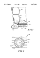
- FIG. 6 is a sectional view taken through a body portion of the auxiliary heat exchanger of the present invention.
- FIG. 7 is a sectional view of another embodiment of the auxiliary heat exchanger.
- FIG. 8 is a sectional view taken through a check valve used in controlling air flow from the air zones of the support surface
- FIG. 9 is a sectional view illustrating a caster locking apparatus of the present invention.
- FIG. 10 is a perspective view of a caster of the bed including the improved locking mechanism in an unlocked position
- FIG. 11 is a perspective view of the caster locking mechanism in a locked position.
- FIG. 1 illustrates a bed 10 of the present invention which includes a base 12 having a plurality of casters 14.
- a frame 16 is coupled to the base 12 by a lifting mechanism 18 discussed below.
- Frame 16 includes an upper articulatable head section 20 which can be raised and lowered to elevate a patient's head.
- a plurality of inflatable air bladders 22 are located above head frame section 20. Air bladders 22 support an upper portion of a patient.
- the bed 10 also includes an air fluidized patient support section 24 which does not articulate.
- Fluidized section 24 is configured to support a lower portion of the patient's body with a fluidized medium which forms a portion of the patient support surface.
- a pair of inflatable rings 26 and 28 best shown in FIGS. 4 and 5 form an outer border 30 of fluidized section 24.
- the rings 26 and 28 are formed from a material impermeable to air. Therefore, the ring bladders 26 and 28 form part of the containment system for holding a fluidizable medium 32 within the fluidized section 24 of bed 10.
- An air permeable sheet 34 is secured to frame assembly 16 to cover and contain the fluidizable medium 32. Suitable means is provided for fastening the sheet 34 to the frame 16, as is well known to those skilled in the art. Further details of the general structure of inflatable air bladders 22 and air fluidized section 24 are disclosed in U.S. Pat. No. 5,623,736, owned by the assignee of the present application, the disclosure of which is incorporated herein by reference.
- the bed 10 also includes a headboard 36, a plurality of siderails 38, and a footboard 40.
- a control panel 42 on the footboard 40 is used to control air flow to the air support bladders, to move the head section 20 of frame 16 between an upwardly angled position and a horizontal position, and to move the frame 16 of bed 10 between its low position and its elevated position.
- FIG. 2 illustrates further details of the frame assembly 16 of bed 10.
- the articulating head frame section 20 is not shown in FIG. 2.
- the articulating head section 20 is coupled to supports 44.
- Side panels 46 and 48 are coupled to opposite sides of frame 16 with suitable fasteners to provide support for the fluidized section 24.
- Corner sections 50 and 52, and end section 54 are also coupled to frame 16 with suitable fasteners to provide support for the fluidized section 24.
- Lifting mechanism 18 includes first arms 56 pivotably coupled to base 12 at locations 58. Opposite ends of first arms 56 are coupled to a tube 60 which slides back and forth within tracks 62 on opposite sides of frame 16. Frame arms 56 are also pivotably coupled to a center bar 64. Center bar 64 is rigidly coupled to second arms 66. Opposite ends of second arms 66 are connected to a sliding mechanism 68 which slides within tracks 70 coupled to base 12. Arms 69 have a first ends pivotably coupled to frame 16 by bar 67 at locations 71. Second ends of arms 69 are rigidly coupled to bar 64. Two drive cylinders 72 are coupled to base 12. Pistons 74 are coupled to the sliding mechanism 68 to move the sliding mechanism 68 back and forth within track 70 in the directions of double headed arrow 76.
- Base 12 includes frame members 78 which are spaced apart a first distance 80.
- Frame members 78 support a blower 82, electronic controller 84, and a plurality of flow control valves 86 within a footprint defined by distance 80 between frame members 78.
- Frame 16 includes side frame members 88 which are space apart by distance 90 which is greater than the distance 80 of spacing between frame members 78 of base 12.
- An end frame member 92 extends between side frame members 88.
- Side frame members 88 and end frame member 92 form an open window 94 which is large enough to pass over blower 82, electronic controller 84, valves 86 which are supported between frame members 78 of base 12.
- frame 16 can be moved to a lower position when pistons 74 are retracted.
- frame 16 can be moved to within 15.6 inches of the ground measured from the bottom surface of frame member 88.
- Diffuser assembly 100 includes a diffuser board 102 which is permeable to air but impermeable to the fluidized medium 32 which, in the preferred embodiment, comprises tiny beads or micro spheres made from glass, ceramics, or silicone.
- Diffuser board 102 is located between first and second perforated metal plates 104 and 106, respectively.
- Metal plates 104 and 106 are formed to include a plurality of apertures 108 and 110 which illustratively cover substantially the entire plates 104 and 106. Apertures 108 and 100 do not extend completely to the edge of plates 104 and 106, as illustrated in FIG. 3.
- FIG. 4 illustrates the diffuser assembly 100 mounted on a base 114 of bed 10 coupled to frame 16. Apertures 108 and 110 in metal plates 104 and 106 begin at about location 116 spaced apart from an end edge 118 of the diffuser assembly 100 as best shown in FIG. 5.
- Use of only a standard diffuser board causes air to pass up along the side of bladder 28 in the direction of arrow 120 to create high air velocity air and "bubbling" adjacent the border 30 of the fluidized section 24.
- the borders 111 and 112 of solid material on plates 104 and 106, respectively, before apertures 108 and 110 begin limits air flow immediately adjacent bladders 28 and 26. This provides more even fluidization as air moves upwardly in the direction of arrows 112 through the diffuser assembly 100.
- the diffuser assembly 100 also provides a ground plane for the air fluidized section 24. This facilitates discharge of static electricity which is generated by the fluidized section. At least one of the plates 104 and 106 is coupled to ground. The plates 104 and 106 are electrically coupled together. Although two metal plates 104 and 106 are shown, it is understood that a single metal plate 104 or 106 may be used in accordance with certain aspects of the present invention.
- Apertures 124 and 126 are formed in diffuser board 102 and plates 104 and 106. Temperature sensors 128 and 130 shown in FIG. 2 extend upwardly through apertures 124 and 126. Sensor 128 is illustratively a temperature probe coupled to electronic controller 84 by wire 132 to regulate the temperature of the fluidized medium up to about 102° F. Sensor 130 is a hardware backup sensor independent of the controller 84 which is configured to deactivate the fluidizing system if the temperature exceeds a predetermined maximum level of about 108° F.
- Air is supplied from blower 82 to a plenum 134 located between diffuser assembly 100 and base 114.
- a main heat exchanger 116 is coupled to base 114 as illustrated in FIG. 4. Air is supplied from blower 82 through an auxiliary heat exchanger 118, through connector 120. Connector 120 is coupled to a supply line which includes an optional heater 122 and heat exchanger 116. Typically, air is heated due to operation of blower 82. Therefore, the main heat exchanger 116 is used to extract heat from the air using liquid in coils 124 or other suitable techniques.
- auxiliary heat exchanger 118 provides an auxiliary heat exchanger 118 through which air flows prior to reaching the main heat exchanger 116.
- Auxiliary heat exchanger 118 is surrounded by a housing 126 including a bottom housing portion 128 and a top housing portion 130.
- a fan 132 is coupled to top housing portion 130. Fan 132 is configured to blow air in the direction of arrow 134 over auxiliary heat exchanger 118 to provide initial cooling of the air from blower 82 before the air from blower 82 reaches the main heat exchanger 116.
- Heat exchanger 118 includes a generally cylindrical body portion 136 for conducting air from the blower 82.
- a plurality of external cooling fins 138 extend outwardly from body 136 to provide a larger surface area for contact with the air from fan 132 moving in the direction of arrow 134.
- Heat exchanger 118 also includes a plurality of inwardly extending fins 140 to provide an increased surface area for contacting the air moving from blower 82 toward the main heat exchanger 116.
- heat exchanger 118 is made from a metal material which conducts heat well.
- Auxiliary heat exchanger 118 pre-cools the air flowing from blower 82 prior to the air entering main heat exchanger 116.
- FIG. 7 Another embodiment of the auxiliary heat exchanger is illustrated in FIG. 7. Those numbers referenced by numbers similar to FIG. 6 perform the same or similar function.
- the outermost cooling fins 138 of heat exchanger 119 are formed to include mounting portions 137 which are configured to receive fasteners (not shown) for mounting a pair of fans illustrated by dotted lines 139 directly to an end portion of the heat exchanger 119.
- the fans 139 may be used in place of fan 132 illustrated in FIG. 4. By directly mounting the fans 139 to a top end of heat exchanger 119, air flow is improved across all of the cooling fins 138.
- the main heat exchanger 116, heater 122, and fan 132 can be controlled by electronic controller 84 to maintain the temperature of the fluidized section 124 at a desired level. Further control of the various air zones of head section bladders 22, air bladders 26 and 28, and fluidized section 24 are disclosed in U.S. Pat. No. 5,623,736.
- the various air zones are provided with a pilot-operated check valve 142 in each pressure line downstream of a pressure control valve as discussed in detail in U.S. Pat. No. 5,623,736.
- the check valve 142 of the present invention illustrated in FIG. 8 is an improvement over the pilot operated check valve disclosed in the '736 patent.
- the check valve 142 is configured to close upon interruption of air supply from the blower 82 to maintain air within the various air zones of the bed 10.
- the check valve 142 includes a body 144 and end caps 146 and 148. End cap 146 is sealed to body 144 with an adhesive, threads, or press fit relationship. End cap 148 is coupled to body 144 by suitable fasteners 150 and sealed with O-ring 152.
- Valve 142 includes a movable valve body 164 having an O-ring seal 166 for engaging a valve seat 168.
- the valve seat 168 of the present invention is illustratively tapered downwardly at an angle of about 15° to improve sealing between the valve seat 168 and the O-ring seal 166 when the valve body 164 is moved to the closed position as illustrated in FIG. 8.
- a spring 170 is located between valve body 164 and cap 148.
- a push rod 170 is coupled to valve body 164.
- Push rod has an enlarged head 172 located within region 184 of valve 142.
- Valve 142 further includes a diaphragm 174, a circular shim 176, and a wave washer 178.
- Cap 146 is formed to include a port 180. Pressure from one of the air zones of bed 10 is coupled to inlet port 154. Port 180 is coupled to an air manifold from blower 82. In operation, pilot air enters port 180 and pushes against diaphragm 174 causing push rod 170 to unseat the O-ring 166 from valve seat 168. Therefore, air entering through inlet 154 can pass through passageways 156 and 162 and exit through outlet 158 as long as blower pressure from the manifold is supplied to port 180.
- valve body 164 and O-ring 166 biases valve body 164 and O-ring 166 against valve seat 168 to prevent air from passing from inlet 154 to outlet 158 in order to maintain air in the various air zones of the bed 10.
- the improved valve 142 of the present invention includes an aperture 182 formed in body 144 in communication with region 184. Aperture 182 forms an air discharge path from region 184 to the atmosphere. Therefore, any air which might leak past push rod 170 through aperture 186 from inlet 154 is discharged to atmosphere. This prevents pressure from building up in region 184 which can equalize the pressure on diaphragm 174 from port 180, thereby causing the spring 170 to close the valve body 164 while the blower 82 is still in operation.
- FIGS. 9-11 An improved caster locking apparatus 190 is illustrated in FIGS. 9-11.
- a stem 191 is configured to be coupled to frame member 192 of base 12.
- Caster 14 is rotatably coupled to stem 191 by bearing 193. Therefore, caster 14 rotates in a conventional manner about axis 194.
- a hub 196 is rigidly coupled to stem 191.
- Caster 14 includes a housing 198 rigidly coupled to caster 14 to rotate with caster 14 about axis 194.
- Housing 198 includes an interior region 200.
- Housing 198 is also includes a pair of first notched portions 202 formed in opposite sidewalls of the housing 198 and a pair of second notched portions 204 formed in the other on spaced apart sidewalls of the housing 198.
- a locking pin 206 is located within interior region 200 of housing 198.
- a spring 208 is also located within interior region 200 of housing 198.
- Spring 208 is configured to engage a flange within interior region 200 to apply a biasing force to a flange 210 of pin 206 to bias the pin 206 upwardly in the direction of arrow 212 within housing 198.
- a ring 214 is configured to be located through an aperture 216 of pin 206 to provide a bottom stop. It is understood that a cross pin or other type of stop may be used in place of ring 214.
- Hub 196 is formed to include spaced apart notched sections 218 configured to receive a top end 207 of pin 206 to lock the caster 14 against rotational movement about axis 194.
- notched sections 218 are spaced every 90° around hub 196.
- the locking mechanism 190 is illustrated in an unlocked position in FIG. 10. In the unlocked position, the ring 214 is oriented to engage the lower notched portions 202 of housing 198 so that the spring 208 is compressed within housing 198 and a top end 207 of locking pin 206 is located at or below a top opening 201 of housing 198. Therefore, the caster 114 and housing 198 are free to rotate relative to hub 196 and frame member 192 in the direction of double headed arrow 218.
Abstract
Description
Claims (25)
Priority Applications (3)
| Application Number | Priority Date | Filing Date | Title |
|---|---|---|---|
| US08/993,183 US6073289A (en) | 1997-12-18 | 1997-12-18 | Air fluidized bed |
| US09/567,671 US6353948B1 (en) | 1997-12-18 | 2000-05-09 | Air fluidized bed |
| US09/997,630 US6574813B2 (en) | 1997-12-18 | 2001-11-29 | Air fluidized bed |
Applications Claiming Priority (1)
| Application Number | Priority Date | Filing Date | Title |
|---|---|---|---|
| US08/993,183 US6073289A (en) | 1997-12-18 | 1997-12-18 | Air fluidized bed |
Related Child Applications (1)
| Application Number | Title | Priority Date | Filing Date |
|---|---|---|---|
| US09/567,671 Division US6353948B1 (en) | 1997-12-18 | 2000-05-09 | Air fluidized bed |
Publications (1)
| Publication Number | Publication Date |
|---|---|
| US6073289A true US6073289A (en) | 2000-06-13 |
Family
ID=25539198
Family Applications (3)
| Application Number | Title | Priority Date | Filing Date |
|---|---|---|---|
| US08/993,183 Expired - Lifetime US6073289A (en) | 1997-12-18 | 1997-12-18 | Air fluidized bed |
| US09/567,671 Expired - Fee Related US6353948B1 (en) | 1997-12-18 | 2000-05-09 | Air fluidized bed |
| US09/997,630 Expired - Fee Related US6574813B2 (en) | 1997-12-18 | 2001-11-29 | Air fluidized bed |
Family Applications After (2)
| Application Number | Title | Priority Date | Filing Date |
|---|---|---|---|
| US09/567,671 Expired - Fee Related US6353948B1 (en) | 1997-12-18 | 2000-05-09 | Air fluidized bed |
| US09/997,630 Expired - Fee Related US6574813B2 (en) | 1997-12-18 | 2001-11-29 | Air fluidized bed |
Country Status (1)
| Country | Link |
|---|---|
| US (3) | US6073289A (en) |
Cited By (41)
| Publication number | Priority date | Publication date | Assignee | Title |
|---|---|---|---|---|
| EP1078623A3 (en) * | 1999-08-27 | 2002-07-31 | Hill-Rom, Inc. | Coverlet for an air bed |
| US6574813B2 (en) * | 1997-12-18 | 2003-06-10 | Hill-Rom Services, Inc. | Air fluidized bed |
| US20030150850A1 (en) * | 2002-02-14 | 2003-08-14 | Jochen Michelmann | Electrical heating element for heating units of seats and steering wheels |
| US20030167568A1 (en) * | 2001-12-20 | 2003-09-11 | Brooke Jason C. | Bed siderails |
| US20040168256A1 (en) * | 2001-07-10 | 2004-09-02 | Chaffee Robert B. | Inflatable device |
| US20040172764A1 (en) * | 1997-10-24 | 2004-09-09 | Hill-Rom Services, Inc. | Mattress |
| US6829796B2 (en) | 2001-10-02 | 2004-12-14 | Hill-Rom Services, Inc. | Integrated barrier and fluid supply for a hospital bed |
| US20060112489A1 (en) * | 2004-04-30 | 2006-06-01 | Bobey John A | Patient support |
| US20060168736A1 (en) * | 2004-04-30 | 2006-08-03 | Meyer Eric R | Pressure relief surface |
| US20060195986A1 (en) * | 2005-03-07 | 2006-09-07 | Reza Hakamiun | Footboard for a hospital bed |
| US20070073365A1 (en) * | 2002-07-03 | 2007-03-29 | Life Support Technologies, Inc. | Methods and apparatus for light therapy |
| US20080127422A1 (en) * | 2006-10-25 | 2008-06-05 | James Joy | Fluidized support bed |
| US20080229508A1 (en) * | 2000-05-17 | 2008-09-25 | Chaffee Robert B | Inflatable device with recessed fluid controller and modified adjustment device |
| US20090217460A1 (en) * | 2005-07-08 | 2009-09-03 | Bobey John A | Patient support |
| US7761945B2 (en) | 2004-05-28 | 2010-07-27 | Life Support Technologies, Inc. | Apparatus and methods for preventing pressure ulcers in bedfast patients |
| US20110138538A1 (en) * | 2009-12-10 | 2011-06-16 | Howell Charles A | Weight efficient fluidized bed |
| US8162009B2 (en) | 2006-04-04 | 2012-04-24 | Chaffee Robert B | Method and apparatus for monitoring and controlling pressure in an inflatable device |
| US8251057B2 (en) | 2003-06-30 | 2012-08-28 | Life Support Technologies, Inc. | Hyperbaric chamber control and/or monitoring system and methods for using the same |
| US8413674B2 (en) | 2000-05-17 | 2013-04-09 | Robert B. Chaffee | Valve with electromechanical device for actuating the valve |
| US8413278B2 (en) | 2006-04-04 | 2013-04-09 | Robert B. Chaffee | Method and apparatus for monitoring and controlling pressure in an inflatable device |
| US8776293B2 (en) | 2001-03-30 | 2014-07-15 | Robert B. Chaffee | Pump with axial conduit |
| USD710509S1 (en) | 2013-09-23 | 2014-08-05 | Hill-Rom Services Pte. Ltd. | Head rail for a patient bed |
| USD710507S1 (en) | 2013-09-23 | 2014-08-05 | Hill-Rom Services Pte. Ltd. | Patient bed |
| USD710510S1 (en) | 2013-09-23 | 2014-08-05 | Hill-Rom Services Pte. Ltd. | Foot rail for a patient bed |
| US9060908B2 (en) | 2013-01-21 | 2015-06-23 | Hill-Rom Services, Inc. | Varying depth fluidized bed |
| US9381127B2 (en) * | 2010-02-26 | 2016-07-05 | Matthew T. Scholz | Patient support systems and methods for transferring patients and controlling patient temperature |
| USD768422S1 (en) | 2014-08-12 | 2016-10-11 | Hill-Rom Services, Inc. | Foot end siderail |
| USD769042S1 (en) | 2014-08-12 | 2016-10-18 | Hill-Rom Services, Inc. | Head end siderail |
| USD770824S1 (en) | 2014-08-12 | 2016-11-08 | Hill-Rom Services, Inc. | Barrier for a hospital bed |
| USD771259S1 (en) | 2015-01-29 | 2016-11-08 | Hill-Rom Services, Inc. | Foot rail for patient bed |
| USD770829S1 (en) | 2015-01-29 | 2016-11-08 | Hill-Rom Services, Inc. | Head rail for patient bed |
| US9737153B2 (en) | 2001-07-10 | 2017-08-22 | Robert B. Chaffee | Configurable inflatable support devices |
| USD804883S1 (en) | 2016-05-28 | 2017-12-12 | Hill-Rom Services, Inc. | Footrail |
| USD804882S1 (en) | 2016-05-28 | 2017-12-12 | Hill-Rom Services, Inc. | Headrail |
| US10137044B2 (en) | 2015-05-14 | 2018-11-27 | Hill-Rom Services, Inc. | Patient support apparatus with sensor assembly |
| US10238560B2 (en) | 2013-03-13 | 2019-03-26 | Hill-Rom Services, Inc. | Air fluidized therapy bed having pulmonary therapy |
| US10437213B2 (en) | 2015-06-19 | 2019-10-08 | Hill-Rom Services, Inc. | Methods and apparatuses for controlling angular orientations of a person support apparatus |
| US10531996B2 (en) | 2015-11-06 | 2020-01-14 | Andrei Cernasov | Supporting surface with programmable supports and method to reduce pressure on selected areas of a body |
| US11246775B2 (en) * | 2017-12-28 | 2022-02-15 | Stryker Corporation | Patient turning device for a patient support apparatus |
| US11357683B2 (en) | 2005-07-08 | 2022-06-14 | Hill-Rom Services, Inc. | Foot zone of a mattress |
| US11389120B2 (en) | 2019-05-30 | 2022-07-19 | Hill-Rom Services, Inc. | Mattress having selectable patient weight valve, inductive power, and a digital x-ray cassette |
Families Citing this family (35)
| Publication number | Priority date | Publication date | Assignee | Title |
|---|---|---|---|---|
| EP1698314B1 (en) * | 2000-03-17 | 2010-04-21 | Stryker Corporation | Stretcher |
| US6865775B2 (en) | 2001-09-05 | 2005-03-15 | Hill-Rom Services, Inc. | Hospital bed caster apparatus |
| ATE456351T1 (en) * | 2003-05-21 | 2010-02-15 | Hill Rom Services Inc | HOSPITAL BED |
| DE602005021483D1 (en) * | 2004-04-15 | 2010-07-08 | Ferno Washington | SELF-INHIBITING SWIVEL WHEEL ROLLERS FOR SICKNESS |
| EP1616718A3 (en) * | 2004-07-15 | 2006-01-25 | Hill-Rom, Inc. | Caster with remotely controlled brake |
| EP1736724A1 (en) * | 2005-06-23 | 2006-12-27 | Enjoy Group AB | Refrigerator with inner shelf carriage and turning device |
| US8104122B2 (en) * | 2005-12-19 | 2012-01-31 | Hill-Rom Services, Inc. | Patient support having an extendable foot section |
| US7922183B2 (en) | 2006-01-19 | 2011-04-12 | Hill-Rom Services, Inc. | Stretcher having hand actuated wheel braking apparatus |
| US7810822B2 (en) * | 2006-01-19 | 2010-10-12 | Hill-Rom Services, Inc. | Stretcher having hand actuated caster braking apparatus |
| US20080127417A1 (en) * | 2006-07-18 | 2008-06-05 | Harty Robert D | Device to isolate fluid draining form surgical patients or contaminated persons |
| FR2913865B1 (en) * | 2007-03-19 | 2009-07-03 | Hill Rom Soc Par Actions Simpl | BEDSPREAD |
| FR2916512B1 (en) | 2007-05-25 | 2013-03-15 | Hill Rom Ind Sa | "PNEUMATIC CONTROL VALVE AND ENERGY RESERVE AND SUPPORT DEVICE, OF MATTRESS TYPE, INCLUDING |
| EP2164715B1 (en) * | 2007-06-06 | 2013-01-09 | Fallshaw Holdings Pty Ltd | A swivel castor braking system |
| WO2009088947A2 (en) | 2008-01-02 | 2009-07-16 | Arcscan, Inc. | Components for an ultrasonic arc scanning apparatus |
| US10531859B2 (en) | 2008-01-02 | 2020-01-14 | Arcscan, Inc. | Components for a precision ultrasonic scanning apparatus for body parts |
| US8496588B2 (en) * | 2008-04-03 | 2013-07-30 | Arcscan, Inc. | Procedures for an ultrasonic arc scanning apparatus |
| EP2299912A4 (en) * | 2008-05-29 | 2013-01-23 | Arcscan Inc | Compound scanning head for an ultrasonic scanning apparatus |
| EP2347745B1 (en) * | 2008-11-07 | 2016-06-29 | Matunaga Manufactory Co. Ltd. | Six-wheeled stretcher |
| US9149254B2 (en) | 2008-12-15 | 2015-10-06 | Arcscan, Inc. | Alignment and imaging of an eye with an ultrasonic scanner |
| US7975337B2 (en) * | 2009-08-19 | 2011-07-12 | Hill-Rom Services, Inc. | Fluidized bed |
| US8510883B2 (en) | 2009-10-30 | 2013-08-20 | Arcscan, Inc. | Method of positioning a patient for medical procedures |
| DE202010010103U1 (en) * | 2010-07-09 | 2011-11-04 | Sudhaus Gmbh & Co. Kg | Castor for suitcases, luggage, transport containers or the like. |
| DE102011109500A1 (en) * | 2010-12-16 | 2012-06-21 | Wabco Gmbh | Compressed air supply system, pneumatic system and method for operating a pneumatic system |
| US9597059B2 (en) | 2012-05-17 | 2017-03-21 | Arcscan, Inc. | Correcting for unintended motion for ultrasonic eye scans |
| US9320427B2 (en) | 2012-07-09 | 2016-04-26 | Arcscan, Inc. | Combination optical and ultrasonic imaging of an eye |
| US20140259427A1 (en) * | 2013-03-13 | 2014-09-18 | Hill-Rom Services, Inc. | Fabric diffuser for fluidized bed |
| US9603764B2 (en) | 2014-02-11 | 2017-03-28 | Medline Industries, Inc. | Method and apparatus for a locking caster |
| WO2015127417A1 (en) | 2014-02-24 | 2015-08-27 | Arcscan, Inc. | Disposable eyepiece system for an ultrasonic eye scanning apparatus |
| US10433652B2 (en) * | 2015-06-22 | 2019-10-08 | Hill-Rom Services, Inc | Person support apparatus with ingress/egress assist |
| US10888301B2 (en) | 2015-10-13 | 2021-01-12 | Arcscan, Inc. | Ultrasonic scanning apparatus |
| US11426611B2 (en) | 2015-10-13 | 2022-08-30 | Arcscan, Inc. | Ultrasound therapeutic and scanning apparatus |
| CN106361533A (en) * | 2016-10-27 | 2017-02-01 | 福建中医药大学 | Spine stability training device |
| CN108186226B (en) * | 2017-12-20 | 2020-02-07 | 冯玉娟 | Self-locking sickbed for medical use based on variable-direction transmission |
| US11628102B2 (en) * | 2018-05-21 | 2023-04-18 | Hill-Rom Services, Inc. | Patient support apparatus adaptable to multiple modes of transport |
| CN112957201A (en) * | 2021-02-02 | 2021-06-15 | 河南省儿童医院郑州儿童医院 | ICU guardianship crib with can be clean by oneself |
Citations (29)
| Publication number | Priority date | Publication date | Assignee | Title |
|---|---|---|---|---|
| US3686696A (en) * | 1970-01-07 | 1972-08-29 | American Hospital Supply Corp | Hospital beds |
| US4481686A (en) * | 1982-03-25 | 1984-11-13 | Lacoste Francois R | Air fluidized bed for therapeutic use |
| US4483029A (en) * | 1981-08-10 | 1984-11-20 | Support Systems International, Inc. | Fluidized supporting apparatus |
| US4556198A (en) * | 1983-12-19 | 1985-12-03 | Fuji Electric Co., Ltd. | Height adjusting lifter for hospital bed |
| US4637083A (en) * | 1985-03-13 | 1987-01-20 | Support Systems International, Inc. | Fluidized patient support apparatus |
| US4745647A (en) * | 1985-12-30 | 1988-05-24 | Ssi Medical Services, Inc. | Patient support structure |
| US4768250A (en) * | 1985-07-30 | 1988-09-06 | Fuji Electric Co., Ltd. | Fluidized bead bed |
| US4768249A (en) * | 1985-12-30 | 1988-09-06 | Ssi Medical Services, Inc. | Patient support structure |
| US4835802A (en) * | 1988-02-22 | 1989-06-06 | The Kmw Group, Inc. | Fluidization patient support control system |
| US4838309A (en) * | 1985-12-30 | 1989-06-13 | Ssi Medical Services, Inc. | Variable flow gas valve |
| EP0332242A2 (en) * | 1988-03-29 | 1989-09-13 | Redactron B.V. | Device for abstracting moisture and fluid from one or more bodies |
| US4879777A (en) * | 1984-01-17 | 1989-11-14 | Support Systems International, Inc. | Fluidized patient support system |
| US4914760A (en) * | 1988-12-20 | 1990-04-10 | Ssi Medical Services, Inc. | Fluidized bed with collapsible side |
| US4935968A (en) * | 1985-05-10 | 1990-06-26 | Mediscus Products, Ltd. | Patient support appliances |
| US4942635A (en) * | 1988-12-20 | 1990-07-24 | Ssi Medical Services, Inc. | Dual mode patient support system |
| US4944060A (en) * | 1989-03-03 | 1990-07-31 | Peery John R | Mattress assembly for the prevention and treatment of decubitus ulcers |
| US4986738A (en) * | 1988-10-12 | 1991-01-22 | Leggett & Platt Incorporated | Airflow control system pump and housing |
| WO1991018578A1 (en) * | 1990-05-28 | 1991-12-12 | Reditac B.V. | Equipment to inactivate matrix at the fluidization therapy |
| US5074000A (en) * | 1991-01-11 | 1991-12-24 | Ssi Medical Services, Inc. | Apparatus for performing head and foot Trendelenburg therapy |
| US5165141A (en) * | 1991-01-11 | 1992-11-24 | Ssi Medical Services, Inc. | Spring loaded heavy duty caster system for supporting a fluidized patient support system |
| US5243723A (en) * | 1992-03-23 | 1993-09-14 | Innovative Medical Systems, Inc. | Multi-chambered sequentially pressurized air mattress with four layers |
| US5272778A (en) * | 1989-01-25 | 1993-12-28 | The Mediscus Group Inc. | Valve useful in low air loss beds |
| US5320187A (en) * | 1992-12-21 | 1994-06-14 | Chicago Pneumatic Tool Company | Mechanical lockout for a pneumatic tool |
| US5394576A (en) * | 1993-06-15 | 1995-03-07 | Ssi Medical Services, Inc. | Patient support system fastening device and method |
| US5402542A (en) * | 1993-04-22 | 1995-04-04 | Ssi Medical Services, Inc. | Fluidized patient support with improved temperature control |
| US5454399A (en) * | 1993-04-08 | 1995-10-03 | Westinghouse Air Brake Company | Application and release magnet valve |
| US5539943A (en) * | 1994-03-08 | 1996-07-30 | Ssi Medical Services, Inc. | Apparatus and method for percussion of fluidized support surface |
| US5586346A (en) * | 1994-02-15 | 1996-12-24 | Support Systems, International | Method and apparatus for supporting and for supplying therapy to a patient |
| US5623736A (en) * | 1994-12-09 | 1997-04-29 | Suport Systems, International | Modular inflatable/air fluidized bed |
Family Cites Families (9)
| Publication number | Priority date | Publication date | Assignee | Title |
|---|---|---|---|---|
| US2544924A (en) * | 1945-10-04 | 1951-03-13 | Bassick Co | Industrial truck caster wheel |
| US4349938A (en) * | 1980-07-11 | 1982-09-21 | Stewart-Warner Corporation | Caster assembly with swivel lock |
| US5183074A (en) * | 1991-09-30 | 1993-02-02 | Cla-Val Co. | Pressure-reducing valve, and aircraft fueling system incorporating the same |
| GB2272368A (en) * | 1992-11-17 | 1994-05-18 | John STONE | Luggage trolley casters |
| US5351364A (en) * | 1993-12-21 | 1994-10-04 | Zun Hong Fu | Caster-supporting device for a stroller |
| US6202672B1 (en) * | 1997-08-25 | 2001-03-20 | Hill-Rom, Inc. | Valve assembly |
| US6073289A (en) * | 1997-12-18 | 2000-06-13 | Hill-Rom, Inc. | Air fluidized bed |
| US6152169A (en) * | 1998-04-20 | 2000-11-28 | Gaymar Industries, Inc. | Pilot operated low pressure shut off valve |
| DE10084246T1 (en) * | 1999-02-19 | 2003-04-24 | Automatic Switch Co | Proportional flow valve with extended flow range |
-
1997
- 1997-12-18 US US08/993,183 patent/US6073289A/en not_active Expired - Lifetime
-
2000
- 2000-05-09 US US09/567,671 patent/US6353948B1/en not_active Expired - Fee Related
-
2001
- 2001-11-29 US US09/997,630 patent/US6574813B2/en not_active Expired - Fee Related
Patent Citations (30)
| Publication number | Priority date | Publication date | Assignee | Title |
|---|---|---|---|---|
| US3686696A (en) * | 1970-01-07 | 1972-08-29 | American Hospital Supply Corp | Hospital beds |
| US4483029A (en) * | 1981-08-10 | 1984-11-20 | Support Systems International, Inc. | Fluidized supporting apparatus |
| US4481686A (en) * | 1982-03-25 | 1984-11-13 | Lacoste Francois R | Air fluidized bed for therapeutic use |
| US4556198A (en) * | 1983-12-19 | 1985-12-03 | Fuji Electric Co., Ltd. | Height adjusting lifter for hospital bed |
| US4879777A (en) * | 1984-01-17 | 1989-11-14 | Support Systems International, Inc. | Fluidized patient support system |
| US4637083A (en) * | 1985-03-13 | 1987-01-20 | Support Systems International, Inc. | Fluidized patient support apparatus |
| US4935968A (en) * | 1985-05-10 | 1990-06-26 | Mediscus Products, Ltd. | Patient support appliances |
| US4768250A (en) * | 1985-07-30 | 1988-09-06 | Fuji Electric Co., Ltd. | Fluidized bead bed |
| US4768249A (en) * | 1985-12-30 | 1988-09-06 | Ssi Medical Services, Inc. | Patient support structure |
| US4838309A (en) * | 1985-12-30 | 1989-06-13 | Ssi Medical Services, Inc. | Variable flow gas valve |
| US4798227A (en) * | 1985-12-30 | 1989-01-17 | Ssi Medical Services, Inc. | Valve for a patient support structure |
| US4745647A (en) * | 1985-12-30 | 1988-05-24 | Ssi Medical Services, Inc. | Patient support structure |
| US4835802A (en) * | 1988-02-22 | 1989-06-06 | The Kmw Group, Inc. | Fluidization patient support control system |
| EP0332242A2 (en) * | 1988-03-29 | 1989-09-13 | Redactron B.V. | Device for abstracting moisture and fluid from one or more bodies |
| US4986738A (en) * | 1988-10-12 | 1991-01-22 | Leggett & Platt Incorporated | Airflow control system pump and housing |
| US4914760A (en) * | 1988-12-20 | 1990-04-10 | Ssi Medical Services, Inc. | Fluidized bed with collapsible side |
| US4942635A (en) * | 1988-12-20 | 1990-07-24 | Ssi Medical Services, Inc. | Dual mode patient support system |
| US5272778A (en) * | 1989-01-25 | 1993-12-28 | The Mediscus Group Inc. | Valve useful in low air loss beds |
| US4944060A (en) * | 1989-03-03 | 1990-07-31 | Peery John R | Mattress assembly for the prevention and treatment of decubitus ulcers |
| WO1991018578A1 (en) * | 1990-05-28 | 1991-12-12 | Reditac B.V. | Equipment to inactivate matrix at the fluidization therapy |
| US5074000A (en) * | 1991-01-11 | 1991-12-24 | Ssi Medical Services, Inc. | Apparatus for performing head and foot Trendelenburg therapy |
| US5165141A (en) * | 1991-01-11 | 1992-11-24 | Ssi Medical Services, Inc. | Spring loaded heavy duty caster system for supporting a fluidized patient support system |
| US5243723A (en) * | 1992-03-23 | 1993-09-14 | Innovative Medical Systems, Inc. | Multi-chambered sequentially pressurized air mattress with four layers |
| US5320187A (en) * | 1992-12-21 | 1994-06-14 | Chicago Pneumatic Tool Company | Mechanical lockout for a pneumatic tool |
| US5454399A (en) * | 1993-04-08 | 1995-10-03 | Westinghouse Air Brake Company | Application and release magnet valve |
| US5402542A (en) * | 1993-04-22 | 1995-04-04 | Ssi Medical Services, Inc. | Fluidized patient support with improved temperature control |
| US5394576A (en) * | 1993-06-15 | 1995-03-07 | Ssi Medical Services, Inc. | Patient support system fastening device and method |
| US5586346A (en) * | 1994-02-15 | 1996-12-24 | Support Systems, International | Method and apparatus for supporting and for supplying therapy to a patient |
| US5539943A (en) * | 1994-03-08 | 1996-07-30 | Ssi Medical Services, Inc. | Apparatus and method for percussion of fluidized support surface |
| US5623736A (en) * | 1994-12-09 | 1997-04-29 | Suport Systems, International | Modular inflatable/air fluidized bed |
Cited By (71)
| Publication number | Priority date | Publication date | Assignee | Title |
|---|---|---|---|---|
| US20040172764A1 (en) * | 1997-10-24 | 2004-09-09 | Hill-Rom Services, Inc. | Mattress |
| US6574813B2 (en) * | 1997-12-18 | 2003-06-10 | Hill-Rom Services, Inc. | Air fluidized bed |
| EP1078623A3 (en) * | 1999-08-27 | 2002-07-31 | Hill-Rom, Inc. | Coverlet for an air bed |
| US9279430B2 (en) | 2000-05-17 | 2016-03-08 | Robert B. Chaffee | Pump with axial conduit |
| US9279510B2 (en) | 2000-05-17 | 2016-03-08 | Robert B. Chaffee | Valve with electromechanical device for actuating the valve |
| US8413674B2 (en) | 2000-05-17 | 2013-04-09 | Robert B. Chaffee | Valve with electromechanical device for actuating the valve |
| US20080229508A1 (en) * | 2000-05-17 | 2008-09-25 | Chaffee Robert B | Inflatable device with recessed fluid controller and modified adjustment device |
| US8826478B2 (en) | 2000-05-17 | 2014-09-09 | Robert B. Chaffee | Inflatable device forming mattresses and cushions |
| US8776293B2 (en) | 2001-03-30 | 2014-07-15 | Robert B. Chaffee | Pump with axial conduit |
| US7475440B2 (en) * | 2001-07-10 | 2009-01-13 | Chaffee Robert B | Inflatable device forming mattresses and cushions |
| US8225444B2 (en) | 2001-07-10 | 2012-07-24 | Chaffee Robert B | Inflatable device forming mattresses and cushions |
| US9737153B2 (en) | 2001-07-10 | 2017-08-22 | Robert B. Chaffee | Configurable inflatable support devices |
| US20040168256A1 (en) * | 2001-07-10 | 2004-09-02 | Chaffee Robert B. | Inflatable device |
| US20090300846A1 (en) * | 2001-07-10 | 2009-12-10 | Chaffee Robert B | Inflatable device forming mattresses and cushions |
| US7310839B2 (en) | 2001-10-02 | 2007-12-25 | Hill-Rom Services, Inc. | Patient support apparatus |
| US20050091753A1 (en) * | 2001-10-02 | 2005-05-05 | Hill-Rom Services, Inc. | Patient support apparatus |
| US6829796B2 (en) | 2001-10-02 | 2004-12-14 | Hill-Rom Services, Inc. | Integrated barrier and fluid supply for a hospital bed |
| US20030167568A1 (en) * | 2001-12-20 | 2003-09-11 | Brooke Jason C. | Bed siderails |
| US7041943B2 (en) * | 2002-02-14 | 2006-05-09 | I G Bauerhin Gmbh | Electrical heating element for heating units of seats and steering wheels |
| US20030150850A1 (en) * | 2002-02-14 | 2003-08-14 | Jochen Michelmann | Electrical heating element for heating units of seats and steering wheels |
| US7815668B2 (en) | 2002-07-03 | 2010-10-19 | Life Support Technologies, Inc. | Methods and apparatus for light therapy |
| US20070073365A1 (en) * | 2002-07-03 | 2007-03-29 | Life Support Technologies, Inc. | Methods and apparatus for light therapy |
| US8251057B2 (en) | 2003-06-30 | 2012-08-28 | Life Support Technologies, Inc. | Hyperbaric chamber control and/or monitoring system and methods for using the same |
| US20060112489A1 (en) * | 2004-04-30 | 2006-06-01 | Bobey John A | Patient support |
| US20110209289A1 (en) * | 2004-04-30 | 2011-09-01 | Meyer Eric R | Pressure relief surface |
| US8146191B2 (en) | 2004-04-30 | 2012-04-03 | Hill-Rom Services, Inc. | Patient support |
| US20060168736A1 (en) * | 2004-04-30 | 2006-08-03 | Meyer Eric R | Pressure relief surface |
| US8196240B2 (en) | 2004-04-30 | 2012-06-12 | Hill-Rom Services, Inc. | Pressure relief surface |
| US7937791B2 (en) | 2004-04-30 | 2011-05-10 | Hill-Rom Services, Inc. | Pressure relief surface |
| US7698765B2 (en) | 2004-04-30 | 2010-04-20 | Hill-Rom Services, Inc. | Patient support |
| US7761945B2 (en) | 2004-05-28 | 2010-07-27 | Life Support Technologies, Inc. | Apparatus and methods for preventing pressure ulcers in bedfast patients |
| US20060195986A1 (en) * | 2005-03-07 | 2006-09-07 | Reza Hakamiun | Footboard for a hospital bed |
| US10507147B2 (en) | 2005-07-08 | 2019-12-17 | Hill-Rom Services, Inc. | Patient support |
| US20090217460A1 (en) * | 2005-07-08 | 2009-09-03 | Bobey John A | Patient support |
| US9707141B2 (en) | 2005-07-08 | 2017-07-18 | Hill-Rom Services, Inc. | Patient support |
| US11357683B2 (en) | 2005-07-08 | 2022-06-14 | Hill-Rom Services, Inc. | Foot zone of a mattress |
| US8162009B2 (en) | 2006-04-04 | 2012-04-24 | Chaffee Robert B | Method and apparatus for monitoring and controlling pressure in an inflatable device |
| US8839474B2 (en) | 2006-04-04 | 2014-09-23 | Robert B. Chaffee | Method and apparatus for monitoring and controlling pressure in an inflatable device |
| US8413278B2 (en) | 2006-04-04 | 2013-04-09 | Robert B. Chaffee | Method and apparatus for monitoring and controlling pressure in an inflatable device |
| US9289073B2 (en) | 2006-04-04 | 2016-03-22 | Robert B. Chaffee | Method and apparatus for monitoring and controlling pressure in an inflatable device |
| US20080127422A1 (en) * | 2006-10-25 | 2008-06-05 | James Joy | Fluidized support bed |
| US7797776B2 (en) * | 2006-10-25 | 2010-09-21 | Aurora Manufacturing Llc | Fluidized support bed |
| US20110138538A1 (en) * | 2009-12-10 | 2011-06-16 | Howell Charles A | Weight efficient fluidized bed |
| US9381127B2 (en) * | 2010-02-26 | 2016-07-05 | Matthew T. Scholz | Patient support systems and methods for transferring patients and controlling patient temperature |
| US9060908B2 (en) | 2013-01-21 | 2015-06-23 | Hill-Rom Services, Inc. | Varying depth fluidized bed |
| US10238560B2 (en) | 2013-03-13 | 2019-03-26 | Hill-Rom Services, Inc. | Air fluidized therapy bed having pulmonary therapy |
| USD710509S1 (en) | 2013-09-23 | 2014-08-05 | Hill-Rom Services Pte. Ltd. | Head rail for a patient bed |
| USD710507S1 (en) | 2013-09-23 | 2014-08-05 | Hill-Rom Services Pte. Ltd. | Patient bed |
| USD710510S1 (en) | 2013-09-23 | 2014-08-05 | Hill-Rom Services Pte. Ltd. | Foot rail for a patient bed |
| USD825973S1 (en) | 2014-08-12 | 2018-08-21 | Hill-Rom Services, Inc. | Barrier for a hospital bed |
| USD769042S1 (en) | 2014-08-12 | 2016-10-18 | Hill-Rom Services, Inc. | Head end siderail |
| USD770824S1 (en) | 2014-08-12 | 2016-11-08 | Hill-Rom Services, Inc. | Barrier for a hospital bed |
| USD817682S1 (en) | 2014-08-12 | 2018-05-15 | Hill-Rom Services, Inc. | Foot end siderail |
| USD819382S1 (en) | 2014-08-12 | 2018-06-05 | Hill-Rom Services, Inc. | Head end siderail |
| USD768422S1 (en) | 2014-08-12 | 2016-10-11 | Hill-Rom Services, Inc. | Foot end siderail |
| USD771259S1 (en) | 2015-01-29 | 2016-11-08 | Hill-Rom Services, Inc. | Foot rail for patient bed |
| USD817058S1 (en) | 2015-01-29 | 2018-05-08 | Hill-Rom Services, Inc. | Head rail for patient bed |
| USD855369S1 (en) | 2015-01-29 | 2019-08-06 | Hill-Rom Services, Inc. | Foot rail for patient bed |
| USD770829S1 (en) | 2015-01-29 | 2016-11-08 | Hill-Rom Services, Inc. | Head rail for patient bed |
| US10137044B2 (en) | 2015-05-14 | 2018-11-27 | Hill-Rom Services, Inc. | Patient support apparatus with sensor assembly |
| US11112761B2 (en) | 2015-06-19 | 2021-09-07 | Hill-Rom Services, Inc. | Methods and apparatuses for controlling angular orientations of a person support apparatus |
| US10437213B2 (en) | 2015-06-19 | 2019-10-08 | Hill-Rom Services, Inc. | Methods and apparatuses for controlling angular orientations of a person support apparatus |
| US10531996B2 (en) | 2015-11-06 | 2020-01-14 | Andrei Cernasov | Supporting surface with programmable supports and method to reduce pressure on selected areas of a body |
| USD858166S1 (en) | 2016-05-28 | 2019-09-03 | Hill-Rom Services, Inc. | Headrail |
| USD850836S1 (en) | 2016-05-28 | 2019-06-11 | Hill-Rom Services, Inc. | Footrail |
| USD804882S1 (en) | 2016-05-28 | 2017-12-12 | Hill-Rom Services, Inc. | Headrail |
| USD804883S1 (en) | 2016-05-28 | 2017-12-12 | Hill-Rom Services, Inc. | Footrail |
| US11246775B2 (en) * | 2017-12-28 | 2022-02-15 | Stryker Corporation | Patient turning device for a patient support apparatus |
| US11730649B2 (en) | 2017-12-28 | 2023-08-22 | Stryker Corporation | Patient turning device for a patient support apparatus |
| US11389120B2 (en) | 2019-05-30 | 2022-07-19 | Hill-Rom Services, Inc. | Mattress having selectable patient weight valve, inductive power, and a digital x-ray cassette |
| US11826185B2 (en) | 2019-05-30 | 2023-11-28 | Hill-Rom Services, Inc. | Mattress having selectable patient weight valve, inductive power, and a digital x-ray cassette |
Also Published As
| Publication number | Publication date |
|---|---|
| US20020032929A1 (en) | 2002-03-21 |
| US6574813B2 (en) | 2003-06-10 |
| US6353948B1 (en) | 2002-03-12 |
Similar Documents
| Publication | Publication Date | Title |
|---|---|---|
| US6073289A (en) | Air fluidized bed | |
| US5623736A (en) | Modular inflatable/air fluidized bed | |
| EP1024733B1 (en) | Mattress having air fluidized sections | |
| US6694555B2 (en) | Air fluidized bladders for a bed | |
| US5647079A (en) | Inflatable patient support surface system | |
| EP0261830B1 (en) | Improved patient support structure | |
| EP0822796B1 (en) | Inflatable lifting device with control apparatus | |
| JPH0470019B2 (en) | ||
| US4949413A (en) | Low air loss bed | |
| CA1279153C (en) | Patient support structure | |
| CA2355964C (en) | Mattress assembly | |
| WO1990000381A1 (en) | Improved fluidized bead bed | |
| US7409735B2 (en) | Dynamic cellular person support surface | |
| US6158070A (en) | Coverlet for an air bed | |
| CA2136445C (en) | Inflatable seat | |
| US5001793A (en) | Vertically actuated array of mattress valves | |
| US20110138538A1 (en) | Weight efficient fluidized bed | |
| EP1139966B1 (en) | Fluidized bead bed with inflatable bead diffuser | |
| MXPA00003749A (en) | Mattress having air fluidized sections |
Legal Events
| Date | Code | Title | Description |
|---|---|---|---|
| AS | Assignment |
Owner name: HILL-ROM, INC., INDIANA Free format text: ASSIGNMENT OF ASSIGNORS INTEREST;ASSIGNORS:BOLDEN, MICHAEL V.;BABSON, VINCENT L.;DENSON, DANIEL A.;REEL/FRAME:008941/0730 Effective date: 19971217 |
|
| STCF | Information on status: patent grant |
Free format text: PATENTED CASE |
|
| AS | Assignment |
Owner name: HILL-ROM SERVICES, INC., INDIANA Free format text: ASSIGNMENT OF ASSIGNORS INTEREST;ASSIGNOR:HILL-ROM, INC.;REEL/FRAME:011796/0440 Effective date: 20010215 |
|
| FEPP | Fee payment procedure |
Free format text: PAYOR NUMBER ASSIGNED (ORIGINAL EVENT CODE: ASPN); ENTITY STATUS OF PATENT OWNER: LARGE ENTITY |
|
| FPAY | Fee payment |
Year of fee payment: 4 |
|
| FPAY | Fee payment |
Year of fee payment: 8 |
|
| FPAY | Fee payment |
Year of fee payment: 12 |
|
| AS | Assignment |
Owner name: JPMORGAN CHASE BANK, N.A., AS COLLATERAL AGENT, ILLINOIS Free format text: SECURITY INTEREST;ASSIGNORS:ALLEN MEDICAL SYSTEMS, INC.;HILL-ROM SERVICES, INC.;ASPEN SURGICAL PRODUCTS, INC.;AND OTHERS;REEL/FRAME:036582/0123 Effective date: 20150908 Owner name: JPMORGAN CHASE BANK, N.A., AS COLLATERAL AGENT, IL Free format text: SECURITY INTEREST;ASSIGNORS:ALLEN MEDICAL SYSTEMS, INC.;HILL-ROM SERVICES, INC.;ASPEN SURGICAL PRODUCTS, INC.;AND OTHERS;REEL/FRAME:036582/0123 Effective date: 20150908 |
|
| AS | Assignment |
Owner name: JPMORGAN CHASE BANK, N.A., AS COLLATERAL AGENT, ILLINOIS Free format text: SECURITY AGREEMENT;ASSIGNORS:HILL-ROM SERVICES, INC.;ASPEN SURGICAL PRODUCTS, INC.;ALLEN MEDICAL SYSTEMS, INC.;AND OTHERS;REEL/FRAME:040145/0445 Effective date: 20160921 Owner name: JPMORGAN CHASE BANK, N.A., AS COLLATERAL AGENT, IL Free format text: SECURITY AGREEMENT;ASSIGNORS:HILL-ROM SERVICES, INC.;ASPEN SURGICAL PRODUCTS, INC.;ALLEN MEDICAL SYSTEMS, INC.;AND OTHERS;REEL/FRAME:040145/0445 Effective date: 20160921 |
|
| AS | Assignment |
Owner name: ANODYNE MEDICAL DEVICE, INC., FLORIDA Free format text: RELEASE BY SECURED PARTY;ASSIGNOR:JPMORGAN CHASE BANK, N.A.;REEL/FRAME:050254/0513 Effective date: 20190830 Owner name: MORTARA INSTRUMENT, INC., WISCONSIN Free format text: RELEASE BY SECURED PARTY;ASSIGNOR:JPMORGAN CHASE BANK, N.A.;REEL/FRAME:050254/0513 Effective date: 20190830 Owner name: MORTARA INSTRUMENT SERVICES, INC., WISCONSIN Free format text: RELEASE BY SECURED PARTY;ASSIGNOR:JPMORGAN CHASE BANK, N.A.;REEL/FRAME:050254/0513 Effective date: 20190830 Owner name: WELCH ALLYN, INC., NEW YORK Free format text: RELEASE BY SECURED PARTY;ASSIGNOR:JPMORGAN CHASE BANK, N.A.;REEL/FRAME:050254/0513 Effective date: 20190830 Owner name: HILL-ROM COMPANY, INC., ILLINOIS Free format text: RELEASE BY SECURED PARTY;ASSIGNOR:JPMORGAN CHASE BANK, N.A.;REEL/FRAME:050254/0513 Effective date: 20190830 Owner name: HILL-ROM SERVICES, INC., ILLINOIS Free format text: RELEASE BY SECURED PARTY;ASSIGNOR:JPMORGAN CHASE BANK, N.A.;REEL/FRAME:050254/0513 Effective date: 20190830 Owner name: ALLEN MEDICAL SYSTEMS, INC., ILLINOIS Free format text: RELEASE BY SECURED PARTY;ASSIGNOR:JPMORGAN CHASE BANK, N.A.;REEL/FRAME:050254/0513 Effective date: 20190830 Owner name: HILL-ROM, INC., ILLINOIS Free format text: RELEASE BY SECURED PARTY;ASSIGNOR:JPMORGAN CHASE BANK, N.A.;REEL/FRAME:050254/0513 Effective date: 20190830 Owner name: VOALTE, INC., FLORIDA Free format text: RELEASE BY SECURED PARTY;ASSIGNOR:JPMORGAN CHASE BANK, N.A.;REEL/FRAME:050254/0513 Effective date: 20190830 |