US6085255A - System and associated method for re-engineering a telecommunications support system with object-oriented translators - Google Patents
System and associated method for re-engineering a telecommunications support system with object-oriented translators Download PDFInfo
- Publication number
- US6085255A US6085255A US09/002,075 US207598A US6085255A US 6085255 A US6085255 A US 6085255A US 207598 A US207598 A US 207598A US 6085255 A US6085255 A US 6085255A
- Authority
- US
- United States
- Prior art keywords
- network
- data
- operational
- operational component
- protocol
- Prior art date
- Legal status (The legal status is an assumption and is not a legal conclusion. Google has not performed a legal analysis and makes no representation as to the accuracy of the status listed.)
- Expired - Lifetime
Links
Images


Classifications
-
- H—ELECTRICITY
- H04—ELECTRIC COMMUNICATION TECHNIQUE
- H04L—TRANSMISSION OF DIGITAL INFORMATION, e.g. TELEGRAPHIC COMMUNICATION
- H04L41/00—Arrangements for maintenance, administration or management of data switching networks, e.g. of packet switching networks
- H04L41/08—Configuration management of networks or network elements
- H04L41/0803—Configuration setting
- H04L41/0813—Configuration setting characterised by the conditions triggering a change of settings
- H04L41/082—Configuration setting characterised by the conditions triggering a change of settings the condition being updates or upgrades of network functionality
-
- H—ELECTRICITY
- H04—ELECTRIC COMMUNICATION TECHNIQUE
- H04L—TRANSMISSION OF DIGITAL INFORMATION, e.g. TELEGRAPHIC COMMUNICATION
- H04L41/00—Arrangements for maintenance, administration or management of data switching networks, e.g. of packet switching networks
- H04L41/02—Standardisation; Integration
- H04L41/022—Multivendor or multi-standard integration
-
- H—ELECTRICITY
- H04—ELECTRIC COMMUNICATION TECHNIQUE
- H04L—TRANSMISSION OF DIGITAL INFORMATION, e.g. TELEGRAPHIC COMMUNICATION
- H04L41/00—Arrangements for maintenance, administration or management of data switching networks, e.g. of packet switching networks
- H04L41/02—Standardisation; Integration
- H04L41/0226—Mapping or translating multiple network management protocols
-
- H—ELECTRICITY
- H04—ELECTRIC COMMUNICATION TECHNIQUE
- H04L—TRANSMISSION OF DIGITAL INFORMATION, e.g. TELEGRAPHIC COMMUNICATION
- H04L41/00—Arrangements for maintenance, administration or management of data switching networks, e.g. of packet switching networks
- H04L41/02—Standardisation; Integration
- H04L41/0233—Object-oriented techniques, for representation of network management data, e.g. common object request broker architecture [CORBA]
-
- H—ELECTRICITY
- H04—ELECTRIC COMMUNICATION TECHNIQUE
- H04L—TRANSMISSION OF DIGITAL INFORMATION, e.g. TELEGRAPHIC COMMUNICATION
- H04L69/00—Network arrangements, protocols or services independent of the application payload and not provided for in the other groups of this subclass
- H04L69/08—Protocols for interworking; Protocol conversion
-
- H—ELECTRICITY
- H04—ELECTRIC COMMUNICATION TECHNIQUE
- H04Q—SELECTING
- H04Q3/00—Selecting arrangements
- H04Q3/0016—Arrangements providing connection between exchanges
- H04Q3/0062—Provisions for network management
- H04Q3/0095—Specification, development or application of network management software, e.g. software re-use
Definitions
- the present invention relates to incrementally restructuring the architecture of a communications network and, in particular, standardizing network management data processing in a telecommunications network.
- Communication networks typically include a plurality of distinct network communication providing components, and network management components.
- the network communication providing components commonly called network elements, provide information transmission services for network users, whereas the network management components manage the traffic flow, resources and accounting relating to use of the network and in particular the network elements. Examples of such networks include: LANS, WANS, and telephony networks.
- network management components known as operational support systems (OSSs), wherein each such OSS may be a relatively complex hardware/software configuration for performing one or more network management functions such as: network monitoring, correcting network performance problems, allocating network resources and billing for network services.
- legacy systems have few common architectural features
- network management systems, network system engineering, and enhanced network element features progressively becomes a more complex and difficult task, particularly, as these advances provide new capabilities utilized most effectively with architectures increasingly at odds with the legacy systems.
- the legacy systems communicate with network elements using a plurality of nonstandard and/or licensed communication protocols, the combination of stopgap maintenance adaptations together with these nonstandard communication protocols have resulted in a complex web of communication channels between operational support systems, and between network elements and operational support systems.
- ISPs International Standardization Profiles from the International Standards Organization (ISO) from the following: Series and Specifications ISO9595-X, ISO9596-X, ISO10165-X, ISO10733 and ISO10164-X; and
- IEC International Electro Technical Commission specifications
- the present invention is a method for incrementally and systematically re-engineering a communications network wherein the present invention is intended to maintain network functionality throughout the re-engineering effort.
- the present invention may be used for replacing certain network management communication channels and management operational support systems in, for example, a telecommunications or telephony network.
- the present invention provides for the systematic and incremental introduction of newer network management systems and network technologies without: (a) prematurely retiring current network elements, and/or (b) abruptly replacing a substantial portion of the present network management as in flash cutting.
- operation component as a network information processing unit having a functionality provided by a network element or an operational support system (OSS) within the network
- OSS operational support system
- the present invention provides a straightforward method for isolating and replacing a network operational component by repeatedly and systematically bypassing, deactivating and/or disconnecting communication channels connected to the operational component wherein each such communication channel or, equivalently, "data channel” is used for transferring data and/or network management commands.
- each communication channel utilizing a protocol that is, for example, nonstandard and specific to a particular (type of) operational component is a primary target for the introduction of an alternative bypass channel that provides: (a) substantially the same communications between the operational components as the target channel, and (b) translates the communications into a standardized communications protocol so that these communications can also be supplied to a network information manager.
- protocol is herein defined to mean:
- function oriented protocol will herein be used to denote the protocols that are nonstandard and specific to the functionality of a particular OSS or a particular vendor network element. That is, for a function oriented protocol, its characteristics according to (4.1) through (4.5) are a combination that can not be cost effectively utilized with different operational components that perform substantially the same functions in the network.
- the present invention includes the following steps:
- the first and second operational components may transfer data on the bypass data path substantially identically to how data is transferred on the target data channel; in particular, the same protocol may be used by the first and second operational components for transferring data on the bypass data path as is used on the target data channel such that it is substantially transparent to both operational components that the bypass data path is being used instead of the target data channel;
- data on the bypass data path is used by (at least one of) the first and second operational components instead of data on the target data channel;
- the bypass data path provides data communicated on it to a network data model for storing and use in modeling the network;
- the (any) required data previously transferred from the second operational component to one of the instances of the first operational component is now supplied to the first operational component by the data model or, more precisely, a data model manager.
- any data previously received by the second operational component on a target or selected data channel for network functionality that must be retained is now received by the fourth operational component(s) via the network data model manager.
- the architecture is substantially consistent with a client-server paradigm wherein this paradigm requires data output by an operational component (e.g., a network element or an OSS) to be supplied to a data manager (i.e., the "server") for capturing (e.g., persistently storing) and for controlling access to the data.
- a data manager i.e., the "server”
- the paradigm provides that such a data manager may coalesce, filter and/or reformulate data supplied to it as when gathering data for a client.
- the previous "direct" receivers of data from a supplying operational component now become clients for the data from the data manager. Therefore, in particular, in steps (5.1) above it is preferred that the bypass data path also transmit data to such a server data (model) manager prior to the data being supplied to the one or more third network operational components (i.e., clients) described in step (5.4) above.
- the client-server architecture provides the capabilities to present a single uniform view of data to clients that is not easily enforced in the operational component to operational component paradigm. For example, if two different data pathways supply similar data having essentially the same semantics but differing values, then the server may manipulate the data from one or both of the pathways so that a consistent single view of the data may be provided to each client.
- the investigation is substantially simplified. In particular, this uniformity of data expedites locating and analyzing certain network malfunctions or faults.
- an "open systems" methodology is incrementally incorporated into the network management architecture by the present invention whereby operational components not supporting open systems communications protocols may also be systematically integrated into an open systems architecture.
- the present invention provides a method for using both the enhanced capabilities of the newer more technically advanced operational components (in particular, network elements) having open systems interfaces and also using older network elements having nonstandard interfaces.
- a network management system is incrementally transformed by the present invention from a system of data channels transferring data in formats that are both substantially specific to each data channel and that are not standardized, into a system having data channels that transfer data as objects and object messages derived from a standardized object class hierarchy developed for the network as a whole.
- the present invention provides translators for restricting the infiltration of vendor specific communication interfaces and data protocols beyond the vendor supplied operational components.
- the translators therefore, translate between: (a) the vendor specific or nonstandard communication protocols and command sets, and (b) the standardized protocols and data architectures used by the remainder of the network management system.
- operational component is also within the scope of the present invention to be utilized in other contexts than with operational components as defined above.
- operational component were generalized to include substantially any network communication suppliers and receivers, such as for example network data bases, as one skilled in the art will recognize.
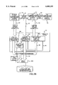
- FIG. 1 is a high level diagram of a representative sample of a telephony network architecture presently used
- FIG. 2 is a high level diagram of a desired telephony network architecture
- FIGS. 3A through 3E are high level diagrams illustrating various network configurations obtained in transforming a network as in FIG. 1 to a network as in FIG. 2 according to the present invention
- FIGS. 4A and 4B provide the high level flowchart of the steps of the present invention.
- FIGS. 5A and 5B provide a more detailed flowchart presenting the steps for providing bypass data paths for nonstandard, function oriented data channels to be deactivated.
- FIG. 1 provides a simplified illustration of some of the typical current telephony network elements together with some of the operational support systems (OSS) currently used in managing a telephony network.
- OSS operational support systems
- Such a network typically includes at least three network management areas 30, 34 and 38. Further, each area includes certain network elements which are in direct communication with specific OSSs via data channels 48 (a, b or c), each data channel being represented by the single and double headed arrows with each arrow head indicating a direction of data and/or command flow through the data channel represented by the arrow's shaft.
- the network management area 30 manages processes and operations related to the completing and terminating of network customer calls.
- the network management area 30 includes the circuit switches 44a and other associated network elements (not shown) for routing and re-routing customer calls, plus, the operational support systems which communicate with the circuit switches 44a via the plurality of data channels 48a.
- the circuit switches 44a shown in network management area 30 are representative of the circuit switches which communicate with OSSs using protocols that are both nonstandard (e.g., specific to a particular vendor), and in addition, function oriented (e.g., the protocols transfer data and/or commands using data structures and data transfer timing that are substantially unique to the functionality of the data supplier and receiver).
- protocol e.g., specific to a particular vendor
- function oriented e.g., the protocols transfer data and/or commands using data structures and data transfer timing that are substantially unique to the functionality of the data supplier and receiver.
- there may be a distinct protocol for substantially every data channel 48a wherein for example, such data channels may communicate a different data type or data at a different sampling rate.
- the OSSs of network management area 30 will now briefly be discussed.
- the loop side provisioning OSS 52 monitors and (re)allocates local loop circuit switch 44a resources.
- the trunk side provisioning OSS 56 monitors and (re)allocates trunk side circuit switch resources.
- the network traffic and usage data acquisition OSS 60 collects circuit switch traffic and usage load data and provides commands to the circuit switches 44a for reconfiguring the circuit switches in order to, for example, balance the network traffic loads between various circuit switches.
- OSS 60 serves as a data filter and communication conduit for the "downstream" network traffic management OSS 64 via data channel 66, this latter OSS being the source of the circuit switch reconfigure commands supplied to the circuit switches 44a.
- the OSS 64 may modify network conditions by sending commands to the network elements 44a to reroute certain user communication requests (e.g., telephone calls) through alternate switches due to capacity limitations (known in the art as “expansive control”), or commands may be sent to a network element 44a restricting the number of user communication requests that are allowed to access a particular network service (known in the art as “restrictive control”).
- both the OSS 60 and the OSS 64 supply report data to a plurality of downstream special purpose report generating OSSs 68 via a plurality of data channels 70 and a plurality of data channels 72, respectively.
- the OSSs 68 generate reports which are, for example, supplied to various state and federal governmental agencies.
- Circuit switches 44a also communicate with an alarms and surveillance OSS 74 for determining network malfunctions and misuse (e.g., fraud). Further, each of the circuit switches 44a provide customer usage information to a billing OSS 76 so that customer usage bills may be determined.
- the network management area 34 manages the processes and operations relating to the transport network elements 80.
- Such transport network elements include trunks and lines having various transmission bandwidth characteristics.
- three of the more common "digital service" transport network element types are shown; i.e., DS0, DS1 and DS3.
- the transport network elements 80a provide data via data channels 48b to a plurality of OSSs, many of which are analogous to the OSSs of the network management area 30.
- Representative of the OSSs for the network management area 34 is an alarms and surveillance OSS 88 that performs substantially the same functions for the transport network elements 80a as OSS 74 does for the circuit switches 44a.
- the OSS 88 also is the data filter and data conduit, via data channel 92, for supplying transport network related data to a plurality of special purpose report generating OSSs 96 which are similar in purpose to the OSSs 68.
- the network management area 38 manages processes and operations related to the SS7 network which, as one skilled in the art will recognize, is a telephony network for communicating internal network control signals for requesting and coordinating the allocation and (de)activation of network resources for network user services.
- the SS7 network is used to configure circuit switches between a caller and a callee, and properly allocate transport network elements 80 between the circuit switches so that a complete end-to-end electronic connection is provided between the caller and the callee.
- the SS7 network includes network elements 100a of a number of different types. Examples of such network elements are: signal transfer points (STP), intelligent service control points (ISCP), service control points (SCP) and service switching points (SSP). Communicating, via the data channels 48c, with the network elements 100a directly are OSSs which are substantially analogous to the OSSs of the network management area 30.
- OSS 104 is analogous to OSS 60
- OSS 116 is analogous to OSS 74
- the OSS 108 is analogous to OSS 64
- OSSs 112 are analogous to OSSs 68.
- the network provisioning OSS 120 is analogous to the combination of OSSs 52 and 56.
- OSS 108 provides commands to the SS7 network elements 100a, via OSS 104, for reconfiguring these network elements according to network traffic.
- FIG. 2 shows a high level block diagram of a network management architecture, into which it is desired to convert the network of FIG. 1.
- the network architecture of FIG. 2 differs from FIG. 1 in the following ways.
- the network architecture of FIG. 2 is based on a client-server paradigm, wherein instead of data channels communicating directly between operational components, the architecture of FIG. 2 requires all data communicated between operational components to be routed through a "server” which may store the data in a persistent data repository but, in any event, distributes the data to "clients", i.e., operational components requesting the data.
- the server includes: (a) the object translator/manager 200, and (b) the object oriented network management information base 204, hereinafter also denoted MIB 204, which is a persistent data and/or object repository.
- the architecture of FIG. 2 is also based on standardized definitions of network data and/or objects (i.e., data records provided with specific behaviors) and data communication formats and protocols.
- these definitions include standardized object definitions related to network elements, network element management and services that use network elements.
- the standardized definitions define an object oriented model of the network and network processes.
- the standards used are derived from the following sources:
- the object translator/manager 200 includes a protocol detector 208 for interfacing with the data channels connected to the object translator/manager 200 (e.g., data channels 212a, 212b, 212c and 216).
- the protocol detector 208 detects messages on the data channels, determines the type of protocol being used to communicate messages on the data channels, and decodes data channel messages in the sense that it determines the object(s) to which each message applies. Additionally, the protocol detector 208 communicates each decoded message to an object model 220a in the form of data packets designating at least an object type (e.g., its class) and one or more attribute values of the object.
- the object model 220a maintains a run time object oriented model of the network based on the standards of (6.2.1) and (6.2.2) above. Thus, the object model 220a:
- (7.2) uses messages received from the protocol detector 208 to update values of object attributes and/or activate particular message specified object methods which may, in turn, update objects in the MIB 204; and/or
- Such messages have a standard format.
- a series of messages will typically be transmitted, via the object translator/manager 200, between two operational components that are in communication.
- such a series of message exchanges between first and second operational components are similar to the following pattern (excluding any intervening activities of the object translator/manager 200):
- the second operational component sends a "message received" message to the first operational component
- the first operational component sends a "request for (particular) data" message or an "execute command” message to the second operational component;
- the second operational component if a request for data message is received, the second operational component sends one or more "requested data" messages to the first operational component having requested the data;
- the first operational component sends a "terminate communication" message to the second operational component
- the second operational component sends a "message received" message to the first operational component.
- the server i.e., object translator/manager 200 and MIB 2064 controls data communications between operational components, prior to data being supplied to an operational component, the operational component is now required to request the data from the server thereby specifying the data objects the operational component wishes to obtain.
- the switch message data channels 212a and the data channels 216 provide data (and/or command) communication between the circuit switches 44b (which may include both circuit switches 44a as shown in FIG. 1 and/or newer standardized circuit switches) and one or more OSSs 224 having standardized object oriented interfaces.
- the data (and/or commands) is now also supplied to the object translator/manager 200.
- the protocol detector 208 intercepts all messages received by the object translator/manager 200 and sends object update messages when appropriate (e.g., steps (8.3) and/or (8.4)) to the object model 220a.
- the protocol detector 208 provides information corresponding to the generic message to the object model 220a thereby allowing the object model to update the persistent switch object in the MIB 204 that is modeling the behavior of this switch so that the switch object maintains an accurate configuration of the switch.
- a method for the switch object is performed that generates a new message to be supplied to the switch, wherein the new message corresponds to the semantics of the generic command message but has a syntax or structure that is specific to the particular switch to which the new message is directed.
- object model 220a to retrieve the object (or its data) from the MIB 204.
- previous state or configuration of the switch (object) is still retained within the MIB 204 as a history or log of switch configurations.
- steps similar to the message transfer steps (8.1)-(8.7) may be performed regardless of the operational components designated as the first and second operational components. Therefore, steps (8.1)-(8.7) also apply, for example, when there are communications between the OSSs 224 and: (a) the SS7 network elements 100b (which may include both SS7 network elements 100a shown in FIG. 1 and/or newer standardized SS7 network elements), or (b) the transfer network elements 80b (which may include both transport network elements 80a and/or newer standardized transport network elements).
- FIG. 2 may offer significant advantages to large network service providers such as telephony service providers. Among these advantages are the following.
- MIBs management information bases
- the MIBs 228 are based on national and/or international recognized standard class definitions for telephony network providers as, for example, cited in (6.2.3) and (6.2.4) above; and
- the architecture of FIG. 2 facilitates enforcement of the use of standardized data objects throughout network management processing.
- the enforcement of this uniformity is likely to lead to less complex and more understandable network management systems in that, for example,
- FIGS. 4 and 5 present an embodiment of the present invention for transforming a network such as FIG. 1 into a network such as FIG. 2.
- FIGS. 3A through 3E illustrate various network configurations that correspond to performing particular steps in FIGS. 4 and 5.
- FIGS. 4 and 5 will be discussed in the context of the network configurations of FIGS. 3A-3E. Further, FIG. 3A will be discussed first so that a more concise context may be provided for the flowcharts of FIGS. 4 and 5.
- FIG. 3A an initial transition network architecture is shown for the method of the present invention.
- the network architecture of FIG. 3A shows the modules which, in the present embodiment of the invention, are needed for incorporating network elements and OSSs communicating using a nonstandard, function oriented architecture as in FIG. 1 into a standardized, open, object oriented network architecture as in FIG. 2.
- FIG. 3A includes three subsystems: a nonstandard, function oriented network management system 300, a standardized, object oriented network management system 304 and a translation system 308.
- the network management system 300 represents a network having an architecture as in FIG. 1.
- network elements 312 may represent, for instance, any two of the network elements of FIG. 1 (i.e., circuit switches 44a, transport network elements 80a and/or SS7 network elements 100a).
- the OSS 316 may represent any of the OSSs (of FIG. 1) directly communicating (via a data channel 48a, b or c) with a network element 312.
- the OSS 320 may represent one of the downstream OSSs of FIG. 1 in communication with an OSS 316 (via data channel 318) that is, in turn, directly communicating with a network element.
- the standardized object oriented network management system 304 represents a network having an architecture as in FIG. 2.
- network elements 324 may represent, for instance, any of the network elements of FIG. 2 (i.e., circuit switches 44b, transport network elements 80b and/or SS7 network elements 100b). It is important to note that at least the object translator/manager 200 and (some portion of) the MIB 204 together with their data connections are necessary to the method of the present invention. On the other hand, the other components and associated data channels of the network management system 304 are optional and may be introduced incrementally as needed.
- a data base management system which may be preferably either objected oriented or relational; and (b) an initial portion of the data base data schema definitions (i.e., table definitions and indexes in relational terms, and object class schema definitions in object oriented terms) sufficient to effectively store data relating to the communications between operational components of the network management system 304.
- the translation system 308 translates between the network management system 300 and the network management system 304.
- the translation done by this system is one way, from the network management system 300 to the network management system 304.
- FIG. 3A shows a network configuration wherein for a selected OSS 316 and at least one network element 312 (in this case two), a data channel 48 is tapped so that data communicated on the data channel 48 may be provided to the translation system 308. (FIG. 3A shows two such data channels 48 being tapped).
- the data being supplied by the data channels 48, via the data channel taps 328, is supplied to the translation module 332 of the translation system 308.
- the translation module 332 translates the data and outputs object attribute values as object messages on data channel 336.
- the object messages output are compatible with the standards cited in (6.2.3) and (6.2.4) above.
- the output object attribute values are shown as being supplied to a second copy of the object model 220a, herein referenced as the object model 220b.
- this second copy is substantially for convenience in describing the invention, there being no inherent necessity for such a second copy to enable the invention.
- the object model 220b has as a primary function the populating of MIB 204 with object data from network management system 300 so that any new object oriented OSSs 224 requesting access to objects derived from such object data may receive these objects.
- this module includes one or more special purpose translators 340 (FIG. 3A shows two such translators) for translating data from the nonstandard network protocols of network management system 300 to the standardized object attribute values output on data channel 336.
- translators 340 FIG. 3A shows two such translators for translating data from the nonstandard network protocols of network management system 300 to the standardized object attribute values output on data channel 336.
- each of the special purpose translators 340 may be used to translate the data and network commands attained from any data channel 48 regardless of the communications and/or protocol on that channel.
- a preferable way to achieve this result is to use identical translators 340 wherein such translators are configurable. That is, each activation of such a translator may read a different "translation mapping" providing different specifications for performing a different translation.
- Such translation mappings are supplied to the translators 340 by a translator mapping table 342 via the translation mapping lines or channels 346, the translator mapping table 342 being a central repository for all the translation mappings that may be needed by the translators 340 in the present and subsequent steps of the present invention.
- the translation mappings are supplied to the translation mapping table 342 by a translation table creation module 350 which uses specifications such as the Bellcore specifications cited in (10.1)-(10.14) above to generate the translation mappings.
- data flowing between the network elements 312 and the OSS 316 is (transparently to the network elements 312 and the OSS 316) conveyed to the translators 340 via the data channel taps 328.
- the translators 340 subsequently translate the data received from the channel taps 328 into object oriented data messages designating at least an object type (e.g., a class) and attribute values of the object to which the message is directed.
- object model 220b which assigns the received object attribute values to the appropriate objects and, for each such updated object, stores in the MIB 204 at least sufficient object data to reconstruct the updated objects.
- object oriented OSSs 224 that request objects updated and/or newly created using the data obtained from one or more data channels 48 may then access the objects via the object translator/manager 200.
- FIG. 4 provides a flow chart of high level steps describing the present invention assuming (at least necessary portions of) the translation system 308, the MIB 204 and the object translator/manager 200 are provided.
- FIG. 4 shows how the present invention may be embodied for isolating one or more operational components concurrently.
- steps 404 through 432 of FIG. 4 describe the modifications to a network such as FIG. 1 for achieving a configuration similar to that of FIG. 3A. That is, these steps illustrate how the present invention provides a tap 328 for one of the data channels 48.
- steps 404 and 408 an operational component and a data channel are selected.
- step 416 a determination is made as to whether the selected data channel should be tapped. An affirmative result from this step may be provided, for example, when (a) it is desirable to populate a data base (e.g., MIB 204), and/or (b) the protocol on the selected data channel is complex and/or unknown and therefore requires a tap for decoding purposes. Subsequently, assuming a tap is to be provided, such as one of the taps 328, the steps 420 through 432 are performed.
- a tap is to be provided, such as one of the taps 328
- the path flow split points 436 and 440 are provided as indications of certain concurrent paths that may be taken in performing the present invention. That is, such paths may be substantially performed in any order and/or in parallel.
- these two path flow split points are merely examples of various concurrencies that may be provided by one skilled in the art. In particular, to illustrate such concurrency in FIG. 4, assume that the upper data channel 48 of FIG. 3A has been tapped as shown in that figure and that it is desirable to tap the lower data channel 48 as shown.
- the flow path 436 through 450 may be followed. Therefore, in step 448 the lower data channel 48 may be chosen as the selected data channel and, in step 450, the lower network element 312 can be chosen as the present operational component. Subsequently, in a further iteration of the steps 416 through 432, the second data channel tap 328 may be provided. Further, note that although not illustrated in FIG. 3A, flow split point 436 provides concurrently for further modifications related to the first tapped data channel 48 via steps 460 through 472 as will be described below.
- an OSS 224 based on the re-engineered network architecture, may be provided for enhancing network services (e.g., providing new reports) wherein the OSS 224 provides requests to the object translator/manager 200 to receive objects whose data has been supplied to the MIB 204 from a tap 328.
- the OSS 224 may receive such objects on an ongoing basis, via the object translator/manager 200 and a data channel 216 according to the steps 452 and 456 of FIG. 4.
- FIG. 4 does not distinguish between types of operational components in the network.
- FIG. 4 is not limited to the sequence or type of operational components selected for isolation in step 404.
- FIG. 3A illustrates the present invention commencing at an OSS 316 directly connected to a network element 312
- the method of FIG. 4 may commence with, for example, downstream OSSs such as an OSS 320 instead, or, even with a network element 312 if it is desirable for such an element to be isolated.
- the flow path having steps 460 through 472 provide the remainder of the network modifications for deactivating a selected data channel enroute to isolating the currently selected operational component.
- FIGS. 3B through 3D show various network configurations that may be obtained during the process of deactivating a data channel. Accordingly, in step 460, the steps of FIG. 5 are performed wherein an alternate or bypass data path between the selected operational component and the present operational component (as described in step 408) is provided for the communications on the selected data channel in a manner that is transparent to the selected and present operational components.
- FIG. 5 shows an alternate or bypass data path between the selected operational component and the present operational component (as described in step 408) is provided for the communications on the selected data channel in a manner that is transparent to the selected and present operational components.
- the bypass includes the data channels 352, 354, 370 and 372 as well as the translators 340a and 340c for transforming data and/or commands between: (a) the protocol utilized by the selected and present operational components, and (b) a protocol acceptable to an object model (such as object model 220b). Therefore, network conditions affected by communications on data channel 48' may now be affected by communications on the bypass. For example, any expansive or restrictive control communication supplied to the network element 312 by the OSS 316 may be supplied via the bypass. Further, note that communications between the selected and present operational components may be concurrently routed through the object model transparently to the selected and present operational components. Further detail regarding step 460 will be given below when discussing the steps of FIG. 5.
- step 468 the selected data channel becomes unnecessary and may therefore be deactivated.
- step 468 any functionality associated exclusively with any tap of the selected data channel is deactivated.
- step 472 the selected data channel is designated as deactivated so that it will not be selected again in step 408.
- each original data channel for the selected operational component may be provided with a bypass data channel (via step 460).
- the affirmative branch from decision step 444 is taken and steps 476 through 480 are performed for isolating the selected operational component.
- step 484 a determination is made as to whether there are further operational components to isolate, if so then step 404 is again performed for selecting a different operational component to isolate. Alternatively, if no other operational component is to be isolated then the network has been re-engineered according to the present invention.
- a series of high level steps are provided for redirecting data and/or commands from a nonstandard data channel to a bypass data channel that may also provide the data and/or commands, in an appropriate form, to an object model such as the object model 220b.
- a translator is provided that can translate between: (a) the nonstandard, function oriented protocol used by the selected operational component, and (b) the standardized object oriented message protocol accepted by the object model.
- a first data path between the selected operational component and the object model is provided wherein the translator is included in the data path.
- FIGS. 3C and 3D examples of a first translator as in steps 504 and 508 are shown in FIGS. 3C and 3D. That is, in FIG. 3C, assuming network element 312 is the present operational component and data channel 48' is the selected data channel, the translator 340a is an example of the first translator provided in step 504 and the data path including: (a) the data channel 352, (b) the translator 340a and (c) the object oriented message channel 354 (between the translator 340a and the object model 220b) is an example of the first data path of step 508.
- FIG. 3C assuming network element 312 is the present operational component and data channel 48' is the selected data channel
- the translator 340a is an example of the first translator provided in step 504 and the data path including: (a) the data channel 352, (b) the translator 340a and (c) the object oriented message channel 354 (between the translator 340a and the object model 220b) is an example of the first data path of step 508.
- translator 340b is an example of the translator of step 504 and the data path including: (a) the data channel 358, (b) the translator 340b and (c) the object oriented message channel 362 (between the translator 340b and the object model 220b) is an example of the first data path of step 508.
- a second translator is provided for translating between: (a) the nonstandard, function oriented protocol used by the present operational component when communicating with the selected operational component, and (b) the object oriented message protocol accepted by the object model.
- a second data path is provided between the present operational component and the object model wherein the second data path includes the second translator.
- translator 340c is an example of the second translator and the data path including: (a) the data channel 370, (b) the translator 340c and the message channel 372 (communicating between the translator 340c and the object model 220b) is an example of the second data path.
- the translator 340d is an example of the second translator of step 512 and the data path including: (a) the data channel 378, (b) the translator 340d, and (c) the object oriented message channel 380 is an example of the second data path.
- the object model is configured to output, on the first data path, object messages derived from object updates caused by the object messages input on the second data path.
- communications from the present operational component to the selected operational component are redirected so that such communication is provided to the selected operational component by the bypass data path including: (a) the second data path, (b) the object model and (c) the first data path.
- the object model 220b is reconfigured so that communications from the network element 312 to the OSS 316 are transmitted via the bypass channel including: (a) the data channel 370, (b) the translator 340c, (c) the data channel 372, (d) the object model 220b, (e) the data channel 354, (f) the translator 340a and (g) the data channel 352.
- the data channel 48' need now only provide data in a single direction, i.e., in the direction of arrow 384.
- the bypass data path communicates data from the OSS 320a to the OSS 316 via, the bypass channel including: (a) the data channel 378, (b) the translator 340d, (c) the data channel 380, (d) the object model 220b, (e) data channel 362, (f) the translator 340b and (g) the data channel 358.
- function oriented data channel 318a is now only required to transfer data in the direction of arrow 388, since communications in the reverse direction may be provided via the bypass data path.
- the object model is configured to also accept data in the reverse direction on the bypass data path and communications from the selected operational component to the present operational component are subsequently also transmitted on the bypass data path.
- data channels 48' and 318a, respectively are superfluous and may therefore be deactivated as is provided in the step 464 of FIG. 4.
- steps 520 and 524 may be exchanged with steps 528 and 532.
- FIGS. 3A through 3E provide a series of intermediate configurations for portions of a network being re-engineered according to this strategy.
- FIG. 3A shows a selected operational component (OSS 316) that is connected directly to a network element wherein a tap into a data channel 48' between the selected operational component and a network element has been performed.
- a network configuration is shown that may be attained once step 524 of FIG. 5 is performed. That is, there is one way communication on the bypass data path from the present operational component to the selected operational component.
- the translators 340'a and 340'c need only have sufficient functionality to translate in one direction. That is, translator 340'c translates communications from a nonstandard, function oriented protocol into a standardized, object oriented message protocol while translator 340'a translates in the opposite direction.
- the configuration of FIG. 3C is provided wherein data channel 48' is now redundant. That is, all communications between network element 312 and OSS 316 use the bypass data path.
- the OSS 316 is required to poll the network element 312 in order to receive network management information from the network element.
- the translators 340a and 340c include polling modules 330a and 330c, respectively, wherein when OSS 316 desires network management information from network element 312, OSS 316 polls translator 340a. Subsequently, the translator 340a uses the polling module 330a to poll translator 340c and subsequently the translator 340c uses the polling module 330c to poll the network element 312. Following this, the requested network management information flows in the reverse direction through the bypass data path from network element 312 to OSS 316.
- steps 448 and 450 may be performed to set the selected data channel to a data channel 318 and set the present operational component to an attached OSS 320. Subsequently, by performing steps 416 through 460, the configuration of FIG. 3D may be attained wherein the selected data channel 318a is redundant. Similarly, by further iteration through the steps of FIGS. 4 and 5, any other data channels such as 318b that do not, as yet, have a corresponding bypass data path can also be made redundant and therefore deactivated.
- step 476 a determination may be made as to whether there is any further functionality provided by the selected operational component that must be retained as part of the network management system. If so, then a new operational component may be provided that is based on standardized network models to perform this functionality. Note that the selected operational component is now redundant and the only data paths remaining connected to it are also connected to the object model. Therefore, these remaining data paths between the selected operational component and the object model may be deactivated as in step 478. At this point, the selected operational component is entirely isolated and may therefore be deactivated. Note that once the deactivation is accomplished, the network will have a configuration including the configuration of FIG. 3E wherein all dashed portions have been deactivated and the OSSs 320 that were communicating directly with the OSS 316 are now communicating via translators 340d with the object model 220b instead.
Abstract
Description
Claims (10)
Priority Applications (1)
| Application Number | Priority Date | Filing Date | Title |
|---|---|---|---|
| US09/002,075 US6085255A (en) | 1995-06-14 | 1998-01-23 | System and associated method for re-engineering a telecommunications support system with object-oriented translators |
Applications Claiming Priority (2)
| Application Number | Priority Date | Filing Date | Title |
|---|---|---|---|
| US08/491,002 US5903731A (en) | 1995-06-14 | 1995-06-14 | System and associated method for re-engineering a telecommunications network support system with object-oriented translators |
| US09/002,075 US6085255A (en) | 1995-06-14 | 1998-01-23 | System and associated method for re-engineering a telecommunications support system with object-oriented translators |
Related Parent Applications (1)
| Application Number | Title | Priority Date | Filing Date |
|---|---|---|---|
| US08/491,002 Division US5903731A (en) | 1995-06-14 | 1995-06-14 | System and associated method for re-engineering a telecommunications network support system with object-oriented translators |
Publications (1)
| Publication Number | Publication Date |
|---|---|
| US6085255A true US6085255A (en) | 2000-07-04 |
Family
ID=23950411
Family Applications (3)
| Application Number | Title | Priority Date | Filing Date |
|---|---|---|---|
| US08/491,002 Expired - Lifetime US5903731A (en) | 1995-06-14 | 1995-06-14 | System and associated method for re-engineering a telecommunications network support system with object-oriented translators |
| US09/057,214 Expired - Lifetime US6055243A (en) | 1995-06-14 | 1998-01-23 | System and associated method for re-engineering a telecommunications support with object-oriented translators |
| US09/002,075 Expired - Lifetime US6085255A (en) | 1995-06-14 | 1998-01-23 | System and associated method for re-engineering a telecommunications support system with object-oriented translators |
Family Applications Before (2)
| Application Number | Title | Priority Date | Filing Date |
|---|---|---|---|
| US08/491,002 Expired - Lifetime US5903731A (en) | 1995-06-14 | 1995-06-14 | System and associated method for re-engineering a telecommunications network support system with object-oriented translators |
| US09/057,214 Expired - Lifetime US6055243A (en) | 1995-06-14 | 1998-01-23 | System and associated method for re-engineering a telecommunications support with object-oriented translators |
Country Status (1)
| Country | Link |
|---|---|
| US (3) | US5903731A (en) |
Cited By (31)
| Publication number | Priority date | Publication date | Assignee | Title |
|---|---|---|---|---|
| US20010002473A1 (en) * | 1998-02-26 | 2001-05-31 | Sun Microsystems, Inc. | Dynamic lookup service in a distributed system |
| US6263366B1 (en) * | 1996-12-31 | 2001-07-17 | Mci Communications Corporation | System and method therefor of translating a message having a given format for usage in an operations system |
| US6389540B1 (en) | 1998-02-26 | 2002-05-14 | Sun Microsystems, Inc. | Stack based access control using code and executor identifiers |
| US6438614B2 (en) * | 1998-02-26 | 2002-08-20 | Sun Microsystems, Inc. | Polymorphic token based control |
| US20020124118A1 (en) * | 2001-01-04 | 2002-09-05 | Colley Adrian E. | Method and system for passing objects in a distributed system using serializatin contexts |
| US6449648B1 (en) | 1996-10-11 | 2002-09-10 | Sun Microsystems, Inc. | Lease renewal service |
| US6466947B2 (en) | 1998-03-20 | 2002-10-15 | Sun Microsystems, Inc. | Apparatus and method for dynamically verifying information in a distributed system |
| US6480863B1 (en) | 1997-11-17 | 2002-11-12 | Sun Microsystems, Inc. | Method and system for multi-entry and multi-template matching in a database |
| US6487607B1 (en) | 1998-02-26 | 2002-11-26 | Sun Microsystems, Inc. | Methods and apparatus for remote method invocation |
| US6519615B1 (en) | 1996-10-11 | 2003-02-11 | Sun Microsystems, Inc. | Method and system for leasing storage |
| US20030061346A1 (en) * | 2001-09-26 | 2003-03-27 | Ar Card | Method and apparatus for secure distributed managed network information services with redundancy |
| US6560656B1 (en) | 1998-02-26 | 2003-05-06 | Sun Microsystems, Inc. | Apparatus and method for providing downloadable code for use in communicating with a device in a distributed system |
| US6564240B2 (en) | 1996-10-11 | 2003-05-13 | Sun Microsystems, Inc. | Method, apparatus, and product for leasing of group membership in a distributed system |
| US6598094B1 (en) | 1998-03-20 | 2003-07-22 | Sun Microsystems, Inc. | Method and apparatus for determining status of remote objects in a distributed system |
| US6604127B2 (en) | 1998-03-20 | 2003-08-05 | Brian T. Murphy | Dynamic lookup service in distributed system |
| US6629154B1 (en) | 1998-02-26 | 2003-09-30 | Sun Microsystems, Inc. | Method and system for deterministic hashes to identify remote methods |
| US6654793B1 (en) | 1996-04-23 | 2003-11-25 | Sun Microsystems, Inc. | System and method for facilitating dynamic loading of stub information to enable a program operating in one address space to invoke processing of a remote method or procedure in another address space |
| US6708171B1 (en) | 1996-04-23 | 2004-03-16 | Sun Microsystems, Inc. | Network proxy |
| US6728737B2 (en) | 1996-10-11 | 2004-04-27 | Sun Microsystems, Inc. | Method and system for leasing storage |
| US6772219B1 (en) * | 1998-09-18 | 2004-08-03 | Kabushiki Kaisha Toshiba | Message relaying scheme based on switching in units of flows |
| US6832223B1 (en) | 1996-04-23 | 2004-12-14 | Sun Microsystems, Inc. | Method and system for facilitating access to a lookup service |
| US20040264440A1 (en) * | 2003-06-25 | 2004-12-30 | Sbc, Inc. | Ring overlay network dedicated to carry broadcast traffic to DSLAMs |
| US6845393B1 (en) | 1999-06-14 | 2005-01-18 | Sun Microsystems, Inc. | Lookup discovery service in a distributed system having a plurality of lookup services each with associated characteristics and services |
| US20050075856A1 (en) * | 2003-10-01 | 2005-04-07 | Sbc Knowledge Ventures, L.P. | Data migration using SMS simulator |
| US7222147B1 (en) * | 2000-05-20 | 2007-05-22 | Ciena Corporation | Processing network management data in accordance with metadata files |
| US7660887B2 (en) | 2001-09-07 | 2010-02-09 | Sun Microsystems, Inc. | Systems and methods for providing dynamic quality of service for a distributed system |
| US7734747B2 (en) | 1998-02-26 | 2010-06-08 | Oracle America, Inc. | Dynamic lookup service in a distributed system |
| US7756969B1 (en) | 2001-09-07 | 2010-07-13 | Oracle America, Inc. | Dynamic provisioning of identification services in a distributed system |
| US7792874B1 (en) | 2004-01-30 | 2010-09-07 | Oracle America, Inc. | Dynamic provisioning for filtering and consolidating events |
| US8495596B1 (en) * | 2009-02-09 | 2013-07-23 | Amdocs Software Systems Limited | System, method, and computer program for interfacing an automatic operational support system with a legacy operational support system |
| US9183066B2 (en) | 1998-03-20 | 2015-11-10 | Oracle America Inc. | Downloadable smart proxies for performing processing associated with a remote procedure call in a distributed system |
Families Citing this family (53)
| Publication number | Priority date | Publication date | Assignee | Title |
|---|---|---|---|---|
| US5903731A (en) * | 1995-06-14 | 1999-05-11 | Us West Technologies, Inc. | System and associated method for re-engineering a telecommunications network support system with object-oriented translators |
| JP2000504868A (en) * | 1996-02-15 | 2000-04-18 | テレフォンアクチボラゲット・エルエム・エリクソン | Management interworking unit and method of forming such a unit |
| ES2290986T3 (en) * | 1997-03-12 | 2008-02-16 | Nomadix, Inc. | NAME TRANSMITTER OR ROUTER. |
| US6389464B1 (en) * | 1997-06-27 | 2002-05-14 | Cornet Technology, Inc. | Device management system for managing standards-compliant and non-compliant network elements using standard management protocols and a universal site server which is configurable from remote locations via internet browser technology |
| EP0899980A1 (en) * | 1997-08-28 | 1999-03-03 | Siemens Aktiengesellschaft | Telecommunication network and state propagation method |
| US6519635B1 (en) * | 1998-04-30 | 2003-02-11 | Cisco Technology, Inc. | SNMP master agent that translates messages to a sub-agent proprietary format using a translation table by the sub-agent |
| US6847384B1 (en) * | 1998-05-14 | 2005-01-25 | Autodesk, Inc. | Translating objects between software applications which employ different data formats |
| US8266266B2 (en) | 1998-12-08 | 2012-09-11 | Nomadix, Inc. | Systems and methods for providing dynamic network authorization, authentication and accounting |
| US8713641B1 (en) | 1998-12-08 | 2014-04-29 | Nomadix, Inc. | Systems and methods for authorizing, authenticating and accounting users having transparent computer access to a network using a gateway device |
| US7194554B1 (en) * | 1998-12-08 | 2007-03-20 | Nomadix, Inc. | Systems and methods for providing dynamic network authorization authentication and accounting |
| AU3740500A (en) * | 1999-03-12 | 2000-09-28 | Nortel Networks Limited | Method and apparatus for accessing network information on a network device |
| US6493323B1 (en) * | 1999-05-14 | 2002-12-10 | Lucent Technologies Inc. | Asynchronous object oriented configuration control system for highly reliable distributed systems |
| EP1079582A1 (en) * | 1999-08-20 | 2001-02-28 | Telefonaktiebolaget L M Ericsson (Publ) | Service parameter interworking method |
| US7116770B1 (en) | 1999-08-25 | 2006-10-03 | Siemens Communications, Inc. | Communication network management |
| US6510203B1 (en) * | 1999-10-20 | 2003-01-21 | Qwest Communications International Inc. | Central office technician notification and information system |
| WO2001031885A2 (en) | 1999-10-22 | 2001-05-03 | Nomadix, Inc. | Gateway device having an xml interface and associated method |
| US7203740B1 (en) * | 1999-12-22 | 2007-04-10 | Intel Corporation | Method and apparatus for allowing proprietary forwarding elements to interoperate with standard control elements in an open architecture for network devices |
| US6868388B1 (en) | 2000-01-19 | 2005-03-15 | Reynolds And Reynolds Holdings, Inc. | Integrated voice and data system and auto retail channel network portal |
| FR2809513B1 (en) * | 2000-05-23 | 2003-09-12 | Bull Sa | QUALITY OF SERVICE CONTROL, ESPECIALLY TELECOMMUNICATION |
| FI20001312A (en) * | 2000-05-31 | 2001-12-01 | Nokia Networks Oy | Formation of a telecommunications network |
| US6836796B2 (en) * | 2001-03-16 | 2004-12-28 | Digi International, Inc. | System and method to manage network-enabled embedded devices operating under various protocols |
| US7571215B2 (en) | 2001-07-16 | 2009-08-04 | Bea Systems, Inc. | Data replication protocol |
| US6918013B2 (en) * | 2001-07-16 | 2005-07-12 | Bea Systems, Inc. | System and method for flushing bean cache |
| US7409420B2 (en) * | 2001-07-16 | 2008-08-05 | Bea Systems, Inc. | Method and apparatus for session replication and failover |
| US7702791B2 (en) * | 2001-07-16 | 2010-04-20 | Bea Systems, Inc. | Hardware load-balancing apparatus for session replication |
| US7028030B2 (en) * | 2001-08-30 | 2006-04-11 | Bea Systems, Inc. | Cluster caching with concurrency checking |
| US7113980B2 (en) * | 2001-09-06 | 2006-09-26 | Bea Systems, Inc. | Exactly once JMS communication |
| US6826601B2 (en) * | 2001-09-06 | 2004-11-30 | Bea Systems, Inc. | Exactly one cache framework |
| US7930704B2 (en) * | 2002-02-06 | 2011-04-19 | Oracle International Corporation | J2EE component extension architecture |
| US7392302B2 (en) | 2002-02-21 | 2008-06-24 | Bea Systems, Inc. | Systems and methods for automated service migration |
| US7506342B2 (en) * | 2002-07-23 | 2009-03-17 | Bea Systems, Inc. | System and method for implementing J2EE connector architecture |
| US7698434B2 (en) * | 2002-08-29 | 2010-04-13 | Bea Systems, Inc. | J2EE connector architecture |
| FR2877174A1 (en) * | 2004-10-25 | 2006-04-28 | France Telecom | NETWORK ADMINISTRATION METHOD, SYSTEM AND DEVICE |
| US8745181B2 (en) * | 2005-12-21 | 2014-06-03 | Rockstar Consortium Us Lp | Generic SNMP information collection |
| US20090006435A1 (en) * | 2007-06-28 | 2009-01-01 | Cisco Technology, Inc. | Object identifier awareness for network device notifications |
| US9083609B2 (en) | 2007-09-26 | 2015-07-14 | Nicira, Inc. | Network operating system for managing and securing networks |
| WO2010115060A2 (en) | 2009-04-01 | 2010-10-07 | Nicira Networks | Method and apparatus for implementing and managing virtual switches |
| US8964528B2 (en) | 2010-07-06 | 2015-02-24 | Nicira, Inc. | Method and apparatus for robust packet distribution among hierarchical managed switching elements |
| US9680750B2 (en) | 2010-07-06 | 2017-06-13 | Nicira, Inc. | Use of tunnels to hide network addresses |
| US8817621B2 (en) | 2010-07-06 | 2014-08-26 | Nicira, Inc. | Network virtualization apparatus |
| US9525647B2 (en) | 2010-07-06 | 2016-12-20 | Nicira, Inc. | Network control apparatus and method for creating and modifying logical switching elements |
| US10103939B2 (en) | 2010-07-06 | 2018-10-16 | Nicira, Inc. | Network control apparatus and method for populating logical datapath sets |
| US8493211B2 (en) * | 2010-09-17 | 2013-07-23 | International Business Machines Corporation | Providing event indications to prevent indication storms in an event model |
| US9043452B2 (en) | 2011-05-04 | 2015-05-26 | Nicira, Inc. | Network control apparatus and method for port isolation |
| US9137107B2 (en) | 2011-10-25 | 2015-09-15 | Nicira, Inc. | Physical controllers for converting universal flows |
| US9203701B2 (en) | 2011-10-25 | 2015-12-01 | Nicira, Inc. | Network virtualization apparatus and method with scheduling capabilities |
| US9288104B2 (en) | 2011-10-25 | 2016-03-15 | Nicira, Inc. | Chassis controllers for converting universal flows |
| US9178833B2 (en) | 2011-10-25 | 2015-11-03 | Nicira, Inc. | Chassis controller |
| AU2013249154B2 (en) | 2012-04-18 | 2015-12-10 | Nicira, Inc. | Exchange of network state information between forwarding elements |
| CN105812317A (en) * | 2014-12-29 | 2016-07-27 | 国家电网公司 | Intelligent substation message mapping method based on data distribution service specifications |
| US9923760B2 (en) | 2015-04-06 | 2018-03-20 | Nicira, Inc. | Reduction of churn in a network control system |
| US10204122B2 (en) | 2015-09-30 | 2019-02-12 | Nicira, Inc. | Implementing an interface between tuple and message-driven control entities |
| US11019167B2 (en) | 2016-04-29 | 2021-05-25 | Nicira, Inc. | Management of update queues for network controller |
Citations (6)
| Publication number | Priority date | Publication date | Assignee | Title |
|---|---|---|---|---|
| US5307484A (en) * | 1991-03-06 | 1994-04-26 | Chrysler Corporation | Relational data base repository system for managing functional and physical data structures of nodes and links of multiple computer networks |
| US5333183A (en) * | 1992-03-13 | 1994-07-26 | Moscom Corporation | Universal MDR data record collection and reporting system |
| US5473599A (en) * | 1994-04-22 | 1995-12-05 | Cisco Systems, Incorporated | Standby router protocol |
| US5499343A (en) * | 1993-12-17 | 1996-03-12 | Taligent, Inc. | Object-oriented networking system with dynamically configurable communication links |
| US5615372A (en) * | 1993-09-08 | 1997-03-25 | Fujitsu Limited | Network definition modifying system |
| US5903731A (en) * | 1995-06-14 | 1999-05-11 | Us West Technologies, Inc. | System and associated method for re-engineering a telecommunications network support system with object-oriented translators |
Family Cites Families (6)
| Publication number | Priority date | Publication date | Assignee | Title |
|---|---|---|---|---|
| WO1992005485A2 (en) * | 1990-09-17 | 1992-04-02 | Cabletron Systems, Inc. | Network management system using model-based intelligence |
| US5317742A (en) * | 1991-06-21 | 1994-05-31 | Racal-Datacom, Inc. | Dynamic translation of network management primitives to queries to a database |
| KR100334689B1 (en) * | 1994-02-28 | 2002-10-04 | 브리티쉬 텔리커뮤니케이션즈 파블릭 리미티드 캄퍼니 | Data storage |
| US5680615A (en) * | 1994-11-04 | 1997-10-21 | International Business Machines Corporation | Desktop management of host applications |
| US5758074A (en) * | 1994-11-04 | 1998-05-26 | International Business Machines Corporation | System for extending the desktop management interface at one node to a network by using pseudo management interface, pseudo component interface and network server interface |
| US5892950A (en) * | 1996-08-09 | 1999-04-06 | Sun Microsystems, Inc. | Interface for telecommunications network management |
-
1995
- 1995-06-14 US US08/491,002 patent/US5903731A/en not_active Expired - Lifetime
-
1998
- 1998-01-23 US US09/057,214 patent/US6055243A/en not_active Expired - Lifetime
- 1998-01-23 US US09/002,075 patent/US6085255A/en not_active Expired - Lifetime
Patent Citations (6)
| Publication number | Priority date | Publication date | Assignee | Title |
|---|---|---|---|---|
| US5307484A (en) * | 1991-03-06 | 1994-04-26 | Chrysler Corporation | Relational data base repository system for managing functional and physical data structures of nodes and links of multiple computer networks |
| US5333183A (en) * | 1992-03-13 | 1994-07-26 | Moscom Corporation | Universal MDR data record collection and reporting system |
| US5615372A (en) * | 1993-09-08 | 1997-03-25 | Fujitsu Limited | Network definition modifying system |
| US5499343A (en) * | 1993-12-17 | 1996-03-12 | Taligent, Inc. | Object-oriented networking system with dynamically configurable communication links |
| US5473599A (en) * | 1994-04-22 | 1995-12-05 | Cisco Systems, Incorporated | Standby router protocol |
| US5903731A (en) * | 1995-06-14 | 1999-05-11 | Us West Technologies, Inc. | System and associated method for re-engineering a telecommunications network support system with object-oriented translators |
Non-Patent Citations (2)
| Title |
|---|
| Sturman, D.C.; "Modular Specification of Interaction Policies in Distributed Computing"; Doctoral Thesis; Univeristy of Illinois; 1996. |
| Sturman, D.C.; Modular Specification of Interaction Policies in Distributed Computing ; Doctoral Thesis; Univeristy of Illinois; 1996. * |
Cited By (41)
| Publication number | Priority date | Publication date | Assignee | Title |
|---|---|---|---|---|
| US6654793B1 (en) | 1996-04-23 | 2003-11-25 | Sun Microsystems, Inc. | System and method for facilitating dynamic loading of stub information to enable a program operating in one address space to invoke processing of a remote method or procedure in another address space |
| US6832223B1 (en) | 1996-04-23 | 2004-12-14 | Sun Microsystems, Inc. | Method and system for facilitating access to a lookup service |
| US6708171B1 (en) | 1996-04-23 | 2004-03-16 | Sun Microsystems, Inc. | Network proxy |
| US6519615B1 (en) | 1996-10-11 | 2003-02-11 | Sun Microsystems, Inc. | Method and system for leasing storage |
| US6449648B1 (en) | 1996-10-11 | 2002-09-10 | Sun Microsystems, Inc. | Lease renewal service |
| US6760736B2 (en) | 1996-10-11 | 2004-07-06 | Sun Microsystems, Inc. | Methods and systems for distributed failure detection and recovery using leasing techniques |
| US6499049B2 (en) | 1996-10-11 | 2002-12-24 | Sun Microsystems, Inc. | Lease renewal service |
| US6816875B2 (en) | 1996-10-11 | 2004-11-09 | Sun Microsystems Inc | Methods, apparatus, and product for distributed garbage collection |
| US6728737B2 (en) | 1996-10-11 | 2004-04-27 | Sun Microsystems, Inc. | Method and system for leasing storage |
| US6704756B2 (en) | 1996-10-11 | 2004-03-09 | Sun Microsystems, Inc. | Methods, apparatus, and product for distributed garbage collection |
| US6564240B2 (en) | 1996-10-11 | 2003-05-13 | Sun Microsystems, Inc. | Method, apparatus, and product for leasing of group membership in a distributed system |
| US6263366B1 (en) * | 1996-12-31 | 2001-07-17 | Mci Communications Corporation | System and method therefor of translating a message having a given format for usage in an operations system |
| US6567820B1 (en) | 1997-11-17 | 2003-05-20 | Sun Microsystems, Inc. | Method and system for in-place modifications in a database |
| US6480863B1 (en) | 1997-11-17 | 2002-11-12 | Sun Microsystems, Inc. | Method and system for multi-entry and multi-template matching in a database |
| US8713089B2 (en) | 1998-02-26 | 2014-04-29 | Oracle America, Inc. | Dynamic lookup service in a distributed system |
| US20010002473A1 (en) * | 1998-02-26 | 2001-05-31 | Sun Microsystems, Inc. | Dynamic lookup service in a distributed system |
| US7734747B2 (en) | 1998-02-26 | 2010-06-08 | Oracle America, Inc. | Dynamic lookup service in a distributed system |
| US6629154B1 (en) | 1998-02-26 | 2003-09-30 | Sun Microsystems, Inc. | Method and system for deterministic hashes to identify remote methods |
| US6438614B2 (en) * | 1998-02-26 | 2002-08-20 | Sun Microsystems, Inc. | Polymorphic token based control |
| US6560656B1 (en) | 1998-02-26 | 2003-05-06 | Sun Microsystems, Inc. | Apparatus and method for providing downloadable code for use in communicating with a device in a distributed system |
| US6389540B1 (en) | 1998-02-26 | 2002-05-14 | Sun Microsystems, Inc. | Stack based access control using code and executor identifiers |
| US6487607B1 (en) | 1998-02-26 | 2002-11-26 | Sun Microsystems, Inc. | Methods and apparatus for remote method invocation |
| US6466947B2 (en) | 1998-03-20 | 2002-10-15 | Sun Microsystems, Inc. | Apparatus and method for dynamically verifying information in a distributed system |
| US9183066B2 (en) | 1998-03-20 | 2015-11-10 | Oracle America Inc. | Downloadable smart proxies for performing processing associated with a remote procedure call in a distributed system |
| US6604127B2 (en) | 1998-03-20 | 2003-08-05 | Brian T. Murphy | Dynamic lookup service in distributed system |
| US6598094B1 (en) | 1998-03-20 | 2003-07-22 | Sun Microsystems, Inc. | Method and apparatus for determining status of remote objects in a distributed system |
| US7310683B2 (en) | 1998-09-18 | 2007-12-18 | Kabushiki Kaisha Toshiba | Message relaying scheme based on switching in units of flows |
| US6772219B1 (en) * | 1998-09-18 | 2004-08-03 | Kabushiki Kaisha Toshiba | Message relaying scheme based on switching in units of flows |
| US6845393B1 (en) | 1999-06-14 | 2005-01-18 | Sun Microsystems, Inc. | Lookup discovery service in a distributed system having a plurality of lookup services each with associated characteristics and services |
| US7222147B1 (en) * | 2000-05-20 | 2007-05-22 | Ciena Corporation | Processing network management data in accordance with metadata files |
| US20020124118A1 (en) * | 2001-01-04 | 2002-09-05 | Colley Adrian E. | Method and system for passing objects in a distributed system using serializatin contexts |
| US7660887B2 (en) | 2001-09-07 | 2010-02-09 | Sun Microsystems, Inc. | Systems and methods for providing dynamic quality of service for a distributed system |
| US7756969B1 (en) | 2001-09-07 | 2010-07-13 | Oracle America, Inc. | Dynamic provisioning of identification services in a distributed system |
| US7124183B2 (en) * | 2001-09-26 | 2006-10-17 | Bell Security Solutions Inc. | Method and apparatus for secure distributed managed network information services with redundancy |
| US20030061346A1 (en) * | 2001-09-26 | 2003-03-27 | Ar Card | Method and apparatus for secure distributed managed network information services with redundancy |
| US7301936B2 (en) | 2003-06-25 | 2007-11-27 | Sbc Knowledge Ventures, L.P. | Ring overlay network dedicated to carry broadcast traffic to DSLAMs |
| US20040264440A1 (en) * | 2003-06-25 | 2004-12-30 | Sbc, Inc. | Ring overlay network dedicated to carry broadcast traffic to DSLAMs |
| US8144721B2 (en) | 2003-06-25 | 2012-03-27 | At&T Intellectual Property 1, Lp | Ring overlay network dedicated to carry broadcast traffic to DSLAMs |
| US20050075856A1 (en) * | 2003-10-01 | 2005-04-07 | Sbc Knowledge Ventures, L.P. | Data migration using SMS simulator |
| US7792874B1 (en) | 2004-01-30 | 2010-09-07 | Oracle America, Inc. | Dynamic provisioning for filtering and consolidating events |
| US8495596B1 (en) * | 2009-02-09 | 2013-07-23 | Amdocs Software Systems Limited | System, method, and computer program for interfacing an automatic operational support system with a legacy operational support system |
Also Published As
| Publication number | Publication date |
|---|---|
| US5903731A (en) | 1999-05-11 |
| US6055243A (en) | 2000-04-25 |
Similar Documents
| Publication | Publication Date | Title |
|---|---|---|
| US6085255A (en) | System and associated method for re-engineering a telecommunications support system with object-oriented translators | |
| US6070188A (en) | Telecommunications network management system | |
| US9300537B2 (en) | Bandwidth-on-demand systems and methods | |
| US6901440B1 (en) | System and method for universal service activation | |
| US7293080B1 (en) | Automatically discovering management information about services in a communication network | |
| US5764955A (en) | Gateway for using legacy telecommunications network element equipment with a common management information protocol | |
| US6233610B1 (en) | Communications network having management system architecture supporting reuse | |
| US6018625A (en) | Management system architecture and design method to support reuse | |
| US20030115305A1 (en) | Command line interface processor with dynamic update of attribute dependencies | |
| EP1551129B1 (en) | Generic interface for subscription management | |
| MXPA01003975A (en) | Method and apparatus for providing real-time call processing services in an intelligent network. | |
| EP0661891B1 (en) | An apparatus for managing an element manager for a telecommunications switch | |
| US6721735B1 (en) | Method and apparatus for synchronizing databases in a network management system | |
| EP0899913A2 (en) | Communications network having management system architecture & design method to support reuse | |
| KR100361474B1 (en) | System Management for Telecommunications Information Networking Architecture(TINA) | |
| CA2237471A1 (en) | Management system architecture & construction method to support reuse | |
| GB2308777A (en) | Telecommunications network management | |
| JP2002527996A (en) | Route selection management in communication networks | |
| KR100454179B1 (en) | Connection Information Correspondence Method Between TMN Agent And Exchange System | |
| WO1997024836A1 (en) | Telecommunications network management system | |
| AU4476999A (en) | A system for managing a telecommunications network | |
| Inamori et al. | " NOSES" as a key technology for realizing advanced telecommunications management | |
| An et al. | TMN-based intelligent network number portability service management system using CORBA | |
| WO1999065187A2 (en) | Network management | |
| CENTER | TMN-based Intelligent Network Number Portability Service Management System Using CORBA |
Legal Events
| Date | Code | Title | Description |
|---|---|---|---|
| AS | Assignment |
Owner name: U S WEST TECHNOLOGIES, INC., COLORADO Free format text: ASSIGNMENT OF ASSIGNORS INTEREST;ASSIGNORS:HALL, CARLTON S.;VINCENT, ALAN W.;REEL/FRAME:009023/0187 Effective date: 19950605 |
|
| AS | Assignment |
Owner name: U S WEST, INC., COLORADO Free format text: ASSIGNMENT OF ASSIGNORS INTEREST;ASSIGNOR:U S WEST TECHNOLOGIES, INC. NOW KNOWN AS U S WEST ADVANCED TECHNOLOGIES, INC.;REEL/FRAME:009187/0978 Effective date: 19980527 |
|
| AS | Assignment |
Owner name: MEDIAONE GROUP, INC., COLORADO Free format text: CHANGE OF NAME;ASSIGNOR:U S WEST, INC.;REEL/FRAME:009297/0442 Effective date: 19980612 Owner name: U S WEST, INC., COLORADO Free format text: ASSIGNMENT OF ASSIGNORS INTEREST;ASSIGNOR:MEDIAONE GROUP, INC.;REEL/FRAME:009297/0308 Effective date: 19980612 Owner name: MEDIAONE GROUP, INC., COLORADO Free format text: ASSIGNMENT OF ASSIGNORS INTEREST;ASSIGNOR:MEDIAONE GROUP, INC.;REEL/FRAME:009297/0308 Effective date: 19980612 |
|
| STCF | Information on status: patent grant |
Free format text: PATENTED CASE |
|
| AS | Assignment |
Owner name: QWEST COMMUNICATIONS INTERNATIONAL INC., COLORADO Free format text: MERGER;ASSIGNOR:U S WEST, INC.;REEL/FRAME:010814/0339 Effective date: 20000630 |
|
| FEPP | Fee payment procedure |
Free format text: PAYER NUMBER DE-ASSIGNED (ORIGINAL EVENT CODE: RMPN); ENTITY STATUS OF PATENT OWNER: LARGE ENTITY Free format text: PAYOR NUMBER ASSIGNED (ORIGINAL EVENT CODE: ASPN); ENTITY STATUS OF PATENT OWNER: LARGE ENTITY |
|
| FPAY | Fee payment |
Year of fee payment: 4 |
|
| FPAY | Fee payment |
Year of fee payment: 8 |
|
| REMI | Maintenance fee reminder mailed | ||
| AS | Assignment |
Owner name: MEDIAONE GROUP, INC. (FORMERLY KNOWN AS METEOR ACQ Free format text: MERGER AND NAME CHANGE;ASSIGNOR:MEDIAONE GROUP, INC.;REEL/FRAME:020893/0162 Effective date: 20000615 Owner name: COMCAST MO GROUP, INC., PENNSYLVANIA Free format text: CHANGE OF NAME;ASSIGNOR:MEDIAONE GROUP, INC. (FORMERLY KNOWN AS METEOR ACQUISITION, INC.);REEL/FRAME:020890/0832 Effective date: 20021118 |
|
| AS | Assignment |
Owner name: QWEST COMMUNICATIONS INTERNATIONAL INC., COLORADO Free format text: ASSIGNMENT OF ASSIGNORS INTEREST;ASSIGNOR:COMCAST MO GROUP, INC.;REEL/FRAME:021624/0155 Effective date: 20080908 |
|
| FPAY | Fee payment |
Year of fee payment: 12 |
|
| AS | Assignment |
Owner name: BANK OF AMERICA, N.A., AS COLLATERAL AGENT, NORTH CAROLINA Free format text: SECURITY INTEREST;ASSIGNOR:QWEST COMMUNICATIONS INTERNATIONAL INC.;REEL/FRAME:044652/0829 Effective date: 20171101 Owner name: BANK OF AMERICA, N.A., AS COLLATERAL AGENT, NORTH Free format text: SECURITY INTEREST;ASSIGNOR:QWEST COMMUNICATIONS INTERNATIONAL INC.;REEL/FRAME:044652/0829 Effective date: 20171101 |