US6097705A - Buffered repeater with independent ethernet collision domains - Google Patents
Buffered repeater with independent ethernet collision domains Download PDFInfo
- Publication number
- US6097705A US6097705A US08/780,654 US78065497A US6097705A US 6097705 A US6097705 A US 6097705A US 78065497 A US78065497 A US 78065497A US 6097705 A US6097705 A US 6097705A
- Authority
- US
- United States
- Prior art keywords
- port
- packet
- brep
- ethernet
- data
- Prior art date
- Legal status (The legal status is an assumption and is not a legal conclusion. Google has not performed a legal analysis and makes no representation as to the accuracy of the status listed.)
- Expired - Lifetime
Links
Images


Classifications
-
- H—ELECTRICITY
- H04—ELECTRIC COMMUNICATION TECHNIQUE
- H04L—TRANSMISSION OF DIGITAL INFORMATION, e.g. TELEGRAPHIC COMMUNICATION
- H04L49/00—Packet switching elements
- H04L49/35—Switches specially adapted for specific applications
- H04L49/351—Switches specially adapted for specific applications for local area network [LAN], e.g. Ethernet switches
-
- H—ELECTRICITY
- H04—ELECTRIC COMMUNICATION TECHNIQUE
- H04L—TRANSMISSION OF DIGITAL INFORMATION, e.g. TELEGRAPHIC COMMUNICATION
- H04L49/00—Packet switching elements
- H04L49/20—Support for services
- H04L49/201—Multicast operation; Broadcast operation
-
- H—ELECTRICITY
- H04—ELECTRIC COMMUNICATION TECHNIQUE
- H04L—TRANSMISSION OF DIGITAL INFORMATION, e.g. TELEGRAPHIC COMMUNICATION
- H04L49/00—Packet switching elements
- H04L49/25—Routing or path finding in a switch fabric
- H04L49/253—Routing or path finding in a switch fabric using establishment or release of connections between ports
- H04L49/254—Centralised controller, i.e. arbitration or scheduling
-
- H—ELECTRICITY
- H04—ELECTRIC COMMUNICATION TECHNIQUE
- H04L—TRANSMISSION OF DIGITAL INFORMATION, e.g. TELEGRAPHIC COMMUNICATION
- H04L49/00—Packet switching elements
- H04L49/50—Overload detection or protection within a single switching element
- H04L49/505—Corrective measures
- H04L49/506—Backpressure
Definitions
- PD25620 "Management of a Computer Network Switched Repeater", by Simoni-Ben Michael, Shuki Perlman, Michael Ben-Nun, and Yifat Ben-Shachar, Ser. No. 08/779,883;
- This invention relates generally to Ethernet repeaters, and more particularly to transfer of data packets from a first Ethernet collision domain to a second Ethernet collision domain.
- Computer networks utilizing Ethernet protocol as described in Standards such as: ANSI/IEEE 802.3, "Carrier Sense Multiple Access with Collision Detection (CSMA/CD) Access Method and Physical Layer Specifications", 1988, 1989; IEEE 802.3b, c, d, and e, 1989 Edition, "Supplements to Carrier Sense Multiple Access with Collision Detection”; ISO/IEC 8802-3, ANSI/IEEE Std 802.3, CSMA/CD “Carrier Sense Multiple Access with Collision Detection Access Method and Physical Layer Specifications”; IEEE Std 802.3u-1995, "Media Access Control (MAC) Parameters, Physical Layer, Medium Attachment Units, and Repeater for 100 Mb/s Operation, Type 100BASE-T", Clauses 21-30; and IEEE Standard 902.9, Local and Metropolitan Area Networks, IEEE Standard Specification of ISLAN15-T, are common today.
- MAC Media Access Control
- a computer network implementing the Carrier Sense Multiple Access Method with Collision Detection (CSMA/CD) method of operation utilizes collision domains.
- a collision domain the stations attached to the network will detect a collision in the event that two or more stations attempt to transmit on the network at the same time.
- a collision domain is limited in its spatial extent by technical factors, principally the speed at which a station can respond to detection of a collision, the speed of transmission on the attachment medium, the length of time of a minimum length message, etc.
- a longstanding problem in design of computer networks is how to provide for forwarding of data packets from a first collision domain to a second collision domain.
- Repeaters as described in Chapter 9 of the ANSI/IEEE Std. 802.3b, c, d, and e 1989 Edition mentioned hereinabove have been used to extend an Ethernet collision domain.
- Bridges which are devices with a store and forward functionality and operative on data packets carrying the destination address of the desired destination end station, have also been used in the past to forward a data packet from a first Ethernet collision domain to a second Ethernet collision domain.
- Routers also a store and forward device and operative on data packets addressed to the router, have been used to forward data packets from a first Ethernet collision domain to a second Ethernet collision domain.
- a repeater device for forwarding a data packet from a first Ethernet collision domain to a second Ethernet collision domain has a plurality of ports, each port for connection to an independent Ethernet collision domain, each port has an associated receive buffer and an associated transmit buffer, and there is a means for forwarding a data packet from the receive buffer of a receiving port to the transmit buffer of a transmitting port.
- a data packet received at the receiving port is then first stored in that port's the receive buffer, is forwarded to the transmit buffer of the transmitting port, and is then transmitted from the transmit buffer by the transmitting port.
- the invention is an Ethernet repeater, having: a receive buffer to hold data received from a first Ethernet collision domain; a transmit buffer to hold data for transmission onto a second Ethernet collision domain; at least one internal bus for broadcast of received data from the receive buffer from the first Ethernet collision domain to the transmit buffer to prepare the received data for transmission onto the second Ethernet collision domain; to enable the transmit buffer, the receive buffer, and the internal bus serve to permit the first Ethernet collision domain and the second Ethernet collision domain to operate as independent Ethernet collision domains.
- the repeater also has a switch having a first switch port and a second switch port; a first internal bus connected to the first switch port, and the first internal bus connected to the receive buffer; a second internal bus connected to the second switch port, the second internal bus connected to the transmit buffer; means for the receive buffer to broadcast onto the first internal bus data received from the first Ethernet collision domain; means for the switch to direct data broadcast onto the first internal bus by the receive buffer to the second internal bus; means for the transmit buffer to receive data broadcast onto the second internal bus, and for the transmit buffer to transmit the data onto the second Ethernet collision domain.
- the repeater has the first Ethernet collision domain operating at a first data rate, and the second Ethernet collision domain operating at a second data rate, and the first data rate is different from the second data rate. Further, the repeater has the at least one internal bus operating at a clock rate which is independent of a data rate of the first Ethernet collision domain and is independent of a data rate of the second Ethernet collision domain.
- a repeater has a means for receiving packets from a source workstation on a first Ethernet collision domain and for transmitting the packets to a destination workstation on a second Ethernet collision domain; a buffer in the repeater for providing temporary storage of a packet received on the first Ethernet collision domain; means, responsive to the buffer being full, for the repeater to generate a collision in the event that a second packet is detected on the first Ethernet collision domain. Further, the repeater has a means for generating the collision by placing a back pressure packet in a transmit buffer of the repeater. In addition, the repeater has means for generating the collision by placing a data packet designated to be transmitted onto the first Ethernet collision domain into a transmit buffer of the repeater.
- FIG. 1 is a sketch of a building having a computer network using hubs installed therein.
- FIG. 2 is a block diagram of a hub.
- FIGS. 3A-3D is a the block diagram of a computer network using hubs.
- FIG. 4 is a field diagram of an Ethernet packet.
- FIG. 5 is a field diagram of a control packet of the invention.
- FIG. 6 is a Table.
- FIG. 7A is an introductory bit sequence for a standard data packet.
- FIG. 7B-FIG. 7G are introductory bit sequences for a control packet.
- FIG. 8A is a block of a switched repeater having multiple segments in a bus and using BREP chips.
- FIG. 8B is a block diagram of a repeater having one segment bus hardwired to a plurality of BREP chips.
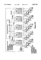
- FIG. 9 is a block diagram of a switched repeater system using BREP chips.
- FIG. 10 is a block diagram of signal pathways in a switched repeater using BREP chips.
- FIG. 11 is a block diagram of a BREP chip showing off-chip signal pathways.
- FIG. 12 is a block diagram of a BREP chip.
- FIG. 13 is a flow chart for internal address filtering.
- FIG. 14 a block diagram for connection of an external CAM to a system using BREP chips for the purpose of address filtering.
- FIG. 15 is a block diagram showing flow control counters.
- FIG. 16 is flow control diagram for establishing half duplex flow control for a link that is capable of running NWay auto-configuration.
- FIG. 17 is a flow control diagram for establishing full duplex flow control for a link that is capable of running NWay auto-configuration.
- FIG. 18 is a flow control diagram for establishing full duplex flow control for a link that is not capable of running NWay auto-configuration.
- FIG. 19 is the management code flow diagram for establishing full-duplex flow control when the link is not capable of running NWay auto-configuration.
- FIG. 20 is a timing diagram for the transmit buffer ready signal.
- FIG. 1 there is shown a building 100 having a computer network 101 installed therein.
- the building 100 is shown in a three dimensional transparent representation, with network components visible through transparent walls, with landscaping 150, and with horizon line 152 to better illustrate the invention.
- An outline of the building 100 is shown, and internal floors are shown in the transparent representation.
- the network is interconnected by hubs 102, 104, 106, 108.
- a hub is made up of one or more Semiconductor Buffered Repeater chips (BREP chips) each having a buffered repeater architecture, and interconnected by a switch engine, as described more fully hereinbelow.
- a hub can support several local area networks, LAN. And each LAN is a separate Ethernet collision domain. Traffic is switched between LANs by the hub.
- BREP chips Semiconductor Buffered Repeater chips
- a wide area network connection enters the building as a cable 110, illustrated as a cable 110 strung on poles 112.
- Cable 110 attaches to router 114.
- Cable 110 can be, for example, a bundle of several optical fibers, can be coaxial cables, can be telephone wires, or any convenient physical media for wide area network connection.
- Router 114 connects to a port of hub 108.
- a second wide area network connection enters the building through an antenna 120 located on the roof 122 of building 100.
- Antenna 120 connects to router 124.
- Antenna 120 can be in communication with a satellite, can be a link in a microwave transmission path, can be a link in an infra red network, or can be any other convenient physical implementation of a communications path.
- Router 124 connects to a port of hub 102.
- the building computer network 101 includes routers 114, 124, hubs 102, 104, 106, 108, the numerous work stations 130 connected to the hubs, and the workstations 141, 142, 143 connected to repeater 140. Through the routers, the building network is connected to wide area networks through, for example, antenna 120 and cable 110. Additionally, for example, building network 101 may include bridges, ATM switches, and so forth. And the network includes the cables connecting each of these components.
- Repeater 140 is shown connected to a port of hub 104. Workstations 141, 142, 143, 144 are shown connected to ports of repeater 140. Repeater 140, the corresponding port of hub 104, and the workstations 141, 142, 143, 144 connected thereto form a single collision domain under the CSMA/CD standard.
- FIG. 2. there is shown a block diagram of the internal architecture of hub 202.
- the hub is a switched repeater, referred to as a SREP repeater.
- the SREP repeater uses Semiconductor Buffered Repeater Chips, referred to as BREP chips.
- Semiconductor Buffered Repeater Chips (BREP chips) 204A, 204B, 204C, 204(N-1), 204N provide Ethernet ports for hub 202.
- each BREP chip provides four (4) Ethernet ports.
- BREP chip 204A has Ethernet ports 204A-1, 204A-2, 204A-3, 204A-4.
- Each of these Ethernet ports may, for example, be adjusted to operate at 10 megabits per second or at 100 megabits per second.
- each of the BREP chips 204A, 204B . . . 204N in hub 202 has four Ethernet ports, as shown in FIG. 2.
- Each port, for example 204A-1, 204A-2, 204A-3, 204A-4, of BREP chips 204A is an independent collision domain operating in accordance with the ANSI/IEEE Standard 802.3, also known as the ISO/IEC 8802-3 standard, as set forth in the Fifth edition Jul. 29, 1996, all disclosures of which are incorporated herein by reference.
- An architecture for a network operating at 10 megabits per second and 100 megabits per second is shown in FIGS. 29.1 and 29.2 of the IEEE 802.3, ISO 8802-3 CSMA/CD Standard. That is, each of the ports provides a carrier sense multiple access with collision detection (CSMA/CD) access method, and each port provides an independent collision domain.
- CSMA/CD carrier sense multiple access with collision detection
- independent LANs provided by each port of a BREP chip is illustrated in FIG. 2.
- BREP chip 204A there is a workstation connected to Ethernet ports 204A-1, 204A-2, and 204A-4.
- Ethernet port 204A-2 is connected to Ethernet repeater 205, and Ethernet repeater 205 is in turn connected to a plurality of workstations indicated as PC1 . . . PCN.
- BREP chip 204B is illustrated by having the ports 204B-1, 204B-3, and 204B-4 connected to workstations, and port 204B-2 connected to an Ethernet Repeater 206.
- the Ethernet Repeater 206 is in turn connected to a plurality of workstations, indicated by the symbol PC1-PCN.
- BREP chip 204C is indicated as connected to workstations at Ethernet ports 204C-1, 204C-2, and 204C-3, and to router 207 at Ethernet port 204C-4. In turn, router 207 connects to a wide area network as illustrated by network cloud 207-1. Likewise, BREP chip 204(N-1) connects to four workstations. And finally, by way of example, BREP chip 204N is shown connected to workstations at its first, second and third ports, while being connected to an Ethernet Repeater 208 at port 254. Ethernet Repeater 208 is then connected to a plurality of workstations, indicated by the symbols, PC1-PCN.
- Each Ethernet port of each BREP chip of hub 202 connects to an independent collision domain as illustrated above: sometimes to a single workstation; sometimes to an Ethernet repeater illustrated as Ethernet repeaters 205 206 208, and then to a plurality of workstations; and, sometimes to a router, illustrated as router 207, connecting to a wide area network as illustrated by network cloud 207-1.
- the BREP chip has a Media Independent Interface (MII) ports or symbol ports that can be connected to a Physical Layer (Phy) device, for example, for operation at either 10 mega-bits per second or operation at 100 mega-bits per second.
- MII Media Independent Interface
- Phy Physical Layer
- the BREP chip can be connected to, for example, a Symbol Phy device for operation at 100 mega-bits per second.
- the PHY device is connected to the physical media using one bit datapath for receive operation, and one bit datapath for transmit operation.
- the BREP chip may be connected to a variety of physical layer devices as are specified in the applicable standards, for example, the standards Standard IEEE 802.3, ISO 8802-3 CSMA/CD Loc al Area Network standards.
- Each Ethernet port has a transmit buffer and a receive buffer, indicated for BREP chip 204A, by the rectangles 210, 212, 214, 216.
- the transmit buffers and the receive buffers are described in more detail hereinbelow, especially in connection with FIG. 11 and FIG. 12. Because of lack of space in FIG. 2 and FIG. 3, a single rectangle will be used to indicate the "transmit and receive" buffers. When a receive function is discussed, the rectangle will be referred to as a receive buffer. When a transmit function is discussed, the rectangle will be referred to as a transmit buffer.
- the individual "transmit and receive" buffers are described in more detail with reference to FIG. 11 and FIG. 12.
- Data associated with Ethernet port 204A-1 is stored in "transmit and receive” buffer 210.
- Data associated with Ethernet port 204A-2 is stored in “transmit and receive” buffer 212.
- Data associated with Ethernet port 204A-3 is stored in “transmit and receive” buffer 214.
- Data associated with Ethernet port 204A-4 is stored in “transmit and receive” buffer 216.
- Data stored in a “transmit and receive” buffer may be waiting to be transmitted out through its associated Ethernet port, or it may have been received from the Ethernet port.
- Each Ethernet port of a BREP chip can be associated to any one of the 4 segment ports, but to only one at a specific time.
- Ethernet port 204A-1 has the associated segment port 220.
- Ethernet port 204A-2 has associated segment port 222.
- Ethernet port 204A-3 has associated segment port 224.
- Ethernet port 204A-4 has associated segment port 226.
- Each of the segment ports for example, may be eight (8) bits wide.
- Each segment port of a BREP chip is independent of the other segment ports.
- the hub 202 contains, for example, four (4) segment busses 230, 232, 234, 236. Each of the segment busses has, for example, an eight-bit wide data path.
- a segment bus may have any number of BREP segment ports attached thereto.
- Each BREP chip port may be associated with any one of the segment busses through control within the BREP chip, and in response to management messages received by the BREP chip.
- Access to the segment bus 230, 232, 234, 236 is controlled by an arbitration mechanism (not shown).
- the segment bus also contains arbitration lines (not shown) for operating the arbitration mechanism, and clock lines (not shown) to operate data transfers along the segment busses.
- "Transmit and receive" buffers 210, 212, 214, 216 in BREP chip 204A and the equivalent “transmit and receive” buffers in each of the other BREP chips, provide buffering between the Ethernet collision domain of their respective Ethernet ports and their respective segment busses 230, 232, 234, 236.
- buffers 210, 212, 214, 216 in BREP chip 204A are shown in FIG.
- each buffer has both a transmit buffer and a receive buffer, as shown in more detail with reference to FIG. 11 and FIG. 12.
- data received at Ethernet port 204A-1 is written to the receive portion of "transmit and receive” buffer 210.
- the receive portion of the "transmit and receive” buffer 210 is then drained by the data being broadcast through segment port 220 to segment bus 236.
- any data broadcast onto segment bus 236 by another BREP chip may be written to the transmit portion of "transmit and receive” buffer 210, and later the transmit portion of the "transmit and receive” buffer 210 is drained by the data being transmitted through Ethernet port 204A-1 onto the Ethernet collision domain attached to Ethernet port 204A-1.
- segment bus 230 is shown attached to: the segment ports of BREP chip 204A at segment port 222 and segment port 224; to BREP chip 204B at segment port 204B-S1; to BREP chip 204C at segment port 204C-S1 and segment port 204C-S3; and, to BREP chip 204(N-1) at all four of its segment ports, 204(N-1)-SP; and finally, for example, segment bus 230 is connected to BREP chip 204N at its segment port 204N-3.
- Segment buses 232, 234, and 236 are shown by way of example, connected to various ports of BREP chip 204A through BREP chip 204N.
- segment bus 230 connects, through the BREP chips, to LANs which are independent Ethernet collision domains operating at 10 megabits per second.
- Segment buses 232, 234, and 236 connect to Ethernet collision domains operating at 100 megabits per second.
- the messages are transmitted from a first collision domain by being received at a receiving BREP chip Ethernet port and the message being stored in a receive buffer.
- the receive buffer is then drained onto the corresponding segment bus and is broadcast to all BREP chip segment ports attached to that segment bus.
- the data is detected by all of the segment ports attached to the segment bus.
- the data is loaded into a segment port transmit buffer after filtering, and is loaded by only those ports of BREP chips permitted by the filtering. Loading the packet into the transmit buffer of a port of a BREP chip places the packet in the transmit queue of that port.
- Filtering may permit loading of the packet by one or more BREP chip segment ports, based on the destination address of the packet: that is there may be a unique destination address; the packet may be a multicast packet; or for example, the packet may be a broadcast packet. Reception of the packet is based on address filtering by the BREP chips. The transmit buffers receiving the packet are then drained by the packet being transmitted through the associated Ethernet port onto its Ethernet LAN.
- Each Ethernet port 204A-1, 204A-2, 204A-3, 204A-4 operates with its associated segment port, as follows:
- Ethernet port 204A-1 connects to "transmit and receive” buffer 210, and "transmit and receive” buffer 210 connects to segment port 220;
- Ethernet port 204A-2 connects to "transmit and receive” buffer 212, and "transmit and receive” buffer 212 connects to segment port 222;
- Ethernet port 204A-3 connects to "transmit and receive” buffer 214, and "transmit and receive” buffer 214 connects to segment port 224;
- Ethernet port 204A-4 connects to "transmit and receive” buffer 216, and "transmit and receive” buffer 216 connects to segment port 226.
- segment ports then connect, by way of example, to the segment busses 230, 232, 234, 236 as follows:
- segment port 220 connects to segment bus 236;
- segment port 222 connects to segment bus 230;
- segment port 224 connects to segment bus 230;
- segment port 226 connects to segment bus 232.
- segment bus 234 does not connect to any segment port of BREP chip 204A, but doe s connect to segment ports of BREP chips 204B, 204C, and 204N.
- the segment busses 230, 232, 234, 236 are labeled by the mega-bits per second (10 or 100) which their associated Ethernet ports, and also external Ethernet collision domains 235 operate. Also, the corresponding switch engine ports are labeled by the mega-bits per second (10 or 100) at which their corresponding Ethernet collision domains 235 operate.
- Switch engine 240 transfers an Ethernet packet from a first segment bus to a second segment bus. Transfer of an Ethernet packet from a first segment bus to a second segment bus is done by switch engine 240.
- Switch engine 240 by way of example, is shown having four (4) ports 242, 246, 248, 250. Segment bus 230 is shown connecting to switch engine port 246. Segment bus 232 is shown connecting to switch engine port 250.
- segment bus 232 connects: to BREP chip 204A at segment port 226; to BREP chip 204B at segment port 204B-S4; to BREP chip 204C at segment port 204C-S4; and, to BREP chip 204N at segment port 204N-S4.
- an Ethernet packet entering BREP chip 204A at Ethernet port 204A-2 by being originated from the collision domain attached to Ethernet port 204A-2, is first stored in receive buffer 212.
- the stored packet is then drained from receive buffer 212 onto segment bus 230 where it enters switch engine 240 at port 246.
- the packet may be switched, by way of example, by switch engine 240 to switch engine port 250, and then onto segment bus 232.
- the Ethernet packet is broadcast to all of the segment ports of the BREP chips attached to segment bus 232, including for example, segment port 204N-4 of BREP chip 204N.
- the packet destination address is located in a computer on the Ethernet collision domain connected to Ethernet port 254, then the packet is stored in transmit buffer 252. From transmit buffer 252 the packet is transmitted through Ethernet port 254 to Ethernet repeater 208. From Ethernet repeater 208 the packet is broadcast to PC1, PC2, . . . PCN. The workstation, say for example PC1, having the destination address of the packet then receives the packet.
- segment bus 230 is shown in FIG. 2 to be operating at 10 megabits per second.
- Segment bus 230 connects to: BREP chip 204A at segment port 222 and segment port 224; BREP chip 204B at segment port 204B-1; BREP chip 204C at segment port 204C-1 and segment port 204C-3; BREP chip 204 (N-1) at all four segment ports 204(N-1)P; and finally, BREP chip 204N at segment port 204N-3.
- each local area network (LAN) which is an Ethernet collision domain, attached to an Ethernet port corresponding to one of these segment ports is operated at 10 megabits per second, including the aforementioned LAN attached to Ethernet port 204A-2.
- Switch engine port 250 is shown operating at 100 megabits per second, as is segment bus 232. Accordingly, all LANs attached to Ethernet ports having their corresponding segment port attached to segment bus 232 operate at 100 megabits per second, including the LAN attached to BREP chip 204N at its Ethernet port 254. Accordingly, the workstations PC1 through PCN, which are attached to repeater 208, operate through the 100 megabits per second Ethernet LAN attached to BREP chip 204N at Ethernet port 254.
- Transmit and receive buffer 252 and “transmit and receive” buffer 212 make it possible for Ethernet packets to be transferred between LANs having different operating bit rates.
- a packet will next be traced from the Ethernet LAN of BREP chip 204A at Ethernet port 204A-2 to a destination on BREP chip 252 at Ethernet port 254, and also in the reverse direction. For example, when a packet originates from the 10 megabit per second LAN connected to Ethernet port 204A-2, the receive buffer 212 is filled at a 10 megabit per second rate. The packet is drained from the receive buffer 212 at the segment bus rate, and the packet enters switch engine 240 at switch engine port 246. The packet is switched by switch engine 240 from switch engine port 246 to switch engine port 250.
- the packet travels on segment bus 232 to transmit buffer 252 of BREP chip 204N at the segment bus clock rate.
- the complete packet is stored in transmit buffer 252.
- Transmit buffer 252 is then drained at 100 megabits per second by transmission through Ethernet port 254 onto the 100 megabit per second LAN where it goes to repeater 208.
- the packet is repeated by repeater 208 at the 100 megabits per second bit rate to the workstations PC1-PCN attached to repeater 208.
- Ethernet packet originated from a workstation such as PC2 connected to repeater 208
- the packet is stored into receive buffer 252 of BREP chip 204N at a 100 megabit per second bit rate.
- Switch engine 240 then provides a connection from its port 250 to its port 246 for the Ethernet packet having a destination address on Ethernet port 204A-2.
- the data is broadcasted at the bus clock rate from BREP chip 204N to transmit buffer 212 of BREP chip 204A.
- the transmit buffer 212 is then drained at the lower 10 megabit per second rate as the packet is transmitted out through Ethernet port 204A-2 of BREP chip 204A to Ethernet repeater 205.
- a packet entering switch repeater 202 and having a destination address which can be reached by broadcast of the packet by the segment bus connected to the corresponding input segment port need not be switched by switch engine 240. That is, a single segment bus is connected to the segment port of the input Ethernet port, and is also connected to the segment port of the outgoing Ethernet port. However in contrast, for an Ethernet packet entering a BREP chip and being broadcast onto a first segment bus that does not reach the destination address of the packet, the switch engine 240 will switch the Ethernet packet to a segment bus having an apparatus with the required destination address communicating therewith, through a corresponding Ethernet port.
- FIGS. 3A-3D there is shown a more complex network 300 including four (4) hubs.
- the network shown in FIGS. 3A-3D could serve as the building network 101 of FIG. 1.
- the topology of network 300 will now be described.
- hub 302 is connected by link 303 to hub 304, and also hub 302 is connected by link 305 to hub 306.
- Hub 306 is connected by link 307 to hub 308.
- Link 303, 305, and 307 may be any convenient message transmission medium.
- link 303, 305, 307 could be twisted pairs, optical fiber links, telephone link connections, coaxial cable, . . . etc.
- Ethernet repeater 312 is connected to port 314 of hub 302.
- Ethernet repeater 312 is connected to a plurality of workstations, illustrated by way of example, by workstations 316, . . . 318.
- repeater 320 is connected to port 322 of hub 302.
- Repeater 320 is in turn connected to a plurality of workstations 323 . . . 324.
- port 326 is connected to router 328.
- Router 328 is in turn connected to a wide-area network illustrated, by way of example, by the network cloud 330.
- repeater 332 is connected to port 324 of hub 304. Repeater 332 is in turn connected to a plurality of workstations 334 . . . 336.
- hub 306 at Ethernet port 341 connects to repeater 340.
- Repeater 340 is connected to a plurality of workstations 342 . . . 344.
- Hub 308 is connected at port 346 to repeater 348. Repeater 348 is then connected to a plurality of workstations 349 . . . 350. Hub 308 is connected at port 352 to repeater 354. Repeater 354 is connected to a plurality of workstations 374 . . .375. Also, by way of example, hub 308 is connected to router 360. By way of example, router 360 is in turn connected to a further wide-area network illustrated by network cloud 362.
- FIG. 3 by way of example, illustrates hub 302, 304, 306, 308, having ports connected to a wide variety of apparatus.
- hub 302 is connected to a plurality of independent workstations 370.
- Reference numeral 370 is used to designate independent workstations attached to various of the hubs 302, 304, 306 and 308.
- Each independent workstation 370 is on a different collision domain, as described hereinabove with reference to FIG. 2.
- hubs 302, 304, 306, 308 are connected to a variety of apparatus, including repeaters, 312, 320, 340, 332, 348, and 354; routers 328, 360. And hubs are connected to other hubs: for example, hub 302 connects to hub 304 through the link 303; hub 302 connects to hub 306 through link 305; and, hub 306 connects to hub 308 through link 307.
- a data packet will be traced from a source workstation to a destination workstation.
- workstation 316 connected through repeater 312 to hub 302, transmits a message having the destination address of workstation 374, connected through repeater 354 at port 352 to hub 308.
- Workstation 316 transmits the data packet to repeater 312.
- a repeater 312, 320, 332, 340, 348, and 354 operates as follows: a repeater receives a packet on one port and broadcasts that packet to all of its other ports.
- a packet transmitted by workstation 316 is received by repeater 312, and repeater 312 broadcasts the packet so that it is received at port 314 of hub 302.
- the packet is written into receive buffer 376 of BREP chip 378.
- Receive buffer 376 is then drained through segment bus 379.
- Segment bus 379 connects to switch engine port 380 of switch engine 382.
- Switch engine 382 interprets the destination address of the packet, and accordingly, switches the packet to its port 384.
- BREP chip 385 loads the packet at its segment port 386.
- the packet is written into transmit buffer 387. Transmit buffer 387 is drained by transmission of the packet onto link 305.
- Segment bus 406 connects, in turn, to segment port 408 of BREP chip 410.
- BREP chip 410 loads the packet, in response to the destination address of the packet, at its segment port 408, and the packet is written into transmit buffer 412 of BREP chip 410.
- Transmit buffer 412 of BREP chip 410 is drained by the packet being transmitted through Ethernet port 352, and the packet is received by repeater 354.
- Repeater 354 transmits the packet to all of the workstations connected to repeater 354, and the packet is received by the intended destination workstation 374.
- FIG. 4 there is illustrated a standard Ethernet packet of the type described in the Ethernet Standard ANSI/IEEE Standard 802.3, Fifth Edition, Jul. 29, 1996, also ISO/IEC 8802-3.
- Preamble 450 is a seven (7) byte field.
- Field SFD 452 is a one (1) byte field.
- Field DA 454 is the destination address field of the packet and is a six (6) byte field, where the field holds the address of the destination workstation.
- Field SA 456 is the source address field of the packet and is a six (6) byte field, where the field holds the address of the source workstation.
- Field “Length” 458 gives the length of the data field of the packet and is a two (2) byte field in IEEE 802.3 packet format indicating length from 0 to 1500 decimal.
- "Ethernet format” length field 458 is a protocol type field having a "value" >1500 decimal.
- Data field 460 is a field having variable length, where the length is specified by the number in field 458 in IEEE 802.3 format.
- PAD field 459 is all zeros and forces the packet length to be 64 bytes, and is present when the data is insufficient to make the packet 64 bytes long. Accordingly, the PAD field may be of length between 0 and 46 bytes.
- the length field 458 specifies the length of the data exclusive of PAD.
- FCS 462 is the frame control sequence field and is four (4) bytes in length.
- the minimum packet size recognized by apparatus constructed according to the Ethernet standard is sixty-four (64) bytes.
- a packet having less than 64 bytes is referred to as a "runt" packet.
- Apparatus constructed in accordance with the Ethernet standard is normally designed to discard runt packets. The detection and rejection of a runt packet is not reported by the apparatus as an error, as there are a number of event sequences which lead to the production of a runt packets, such as, for example, a collision in half duplex Ethernet. The apparatus simply discards any runt packet which it detects.
- FIG. 5 there is shown a control packet 500 for use in automatic detection of the type of apparatus attached to a port of a BREP chip.
- Fields of the control packet include the preamble field 502 which is a seven (7) byte field.
- Field SFZ 504 is a one (1) byte field. Details of field SFZ 504 will be discussed hereinbelow with reference to FIG. 7A-FIG. 7G. Field SFZ 504, in a preferred embodiment of the invention, permits a BREP chip to recognize that a received packet came from a device having the capabilities of a BREP chip.
- the destination address field 454 is labeled with the same reference numeral as the DA field of FIG. 4 because the destination address of the standard packet is utilized in the destination address of the control packet.
- Source address field 456 is labeled with the same reference numeral as the source address field SA of FIG. 4 because the control packet uses the standard source address as described in the Ethernet standard.
- Length/Type field 506 in a preferred embodiment of the invention, is used as a TYPE field using Ethernet format.
- the TYPE field is programmable, so a special TYPE value distinguishes a control frame from a normal frame.
- OpCode field 510 carries an operations code recognized by a receiving port of a BREP chip, and is two (2) bytes in length.
- the op-code field is programmable, and for an exemplary embodiment of the invention the op-codes of the following table may be used.
- Credit field 512 carries credit for use in a credit based flow control mechanism which may be established between a first hub having a BREP chip and a second hub connected to a port of that BREP chip, where the second hub uses BREP chips.
- Padding field 514 contains sufficient bytes to make the control packet 64 bytes in length. Accordingly, padding field 514 contains forty-two (42) bytes.
- FCS field 462 the frame control sequence field, is labeled with the same reference numeral as the standard packet shown in FIG. 4 because the frame control sequence field usage is in accordance with the Ethernet standard.
- FIG. 6 is a table giving the fields of control packet 500.
- the total number of bytes is 64, and the padding of 42 bytes is used to ensure that the length of the control packet is sufficient so that it is not a runt packet.
- FIG. 7A through FIG. 7G there is shown: the content of preamble field 450 and SFD field 452 (shown in FIG. 4) of the standard packet; and the preamble field 502 and the SFZ field 504 of control packet 500.
- the content of these fields from FIG. 4 is shown in greater detail in FIG. 7A-FIG. 7G.
- FIG. 7A a standard preamble 702 is shown. Also, in FIG. 7A, a standard SFD 452 byte is shown in field 704. It is noted that the standard preamble 702 is made up of seven (7) identical bytes with the following: "10101010" bit pattern. Further, as shown in FIG. 7A, the standard SFD byte is 10101011.
- the apparatus When an apparatus built in accordance with the Ethernet standard receives at least seven (7) bytes of the standard preamble, that is 56 repeating "10" symbols, followed by a single SFD byte, the apparatus recognizes that the destination address field 454 immediately follows the "11" content of the SFD byte.
- the preamble 706 of the control packet 708 is identical with the standard preamble 702 shown in FIG. 7A.
- the SFZ byte 504, shown in FIG. 7B as field 710 is as follows: 10101000.
- the BREP chip is designed to recognize the SFZ byte 710 after receipt of at least fifty-six (56) bits of repeating "10" of the standard preamble 702. Upon detection by the Ethernet port of the BREP chip that the SFZ byte has been received, the BREP chip interprets the packet as a control packet.
- Reception of the control packet guarantees that the other end of a wire connected to the BREP chip port is connected in turn to another BREP chip port. This guarantee flows from the point that any apparatus built according to the Ethernet standard will not forward a control packet.
- the existence of the SFZ byte in the control packet is sufficient for an apparatus built in accordance with the Ethernet standard to fail to interpret the packet as a "packet".
- An apparatus built according to the Ethernet standard requires the "11" sequence following a standard preamble.
- the existence of the "00" sequence of field 710 prevents the apparatus from detecting that a packet has been received.
- ports of a BREP chip may have any number of different types of apparatus attached thereto.
- a repeater 312, 320, 340, 332, 348, 354 is illustrated as attached to a port of a BREP chip
- a router 328, 360 is illustrated as attached to a port of a BREP chip
- two BREP chips are illustrated as being connected together, for example, by links 303, 305, and 307.
- numerous workstations 370 are shown connected directly to a port of a BREP chip.
- No forwarding apparatus such as a bridge, router or switching hub, etc. will forward a packet having a SFZ field, and no workstation will transmit a packet having a SFZ field. Accordingly, when a receiving port of a BREP chip detects the presence of a control packet by detection of the SFZ 710 byte following a standard preamble 702, then the receiving BREP chip port has determined that it is connected to another BREP chip port, as for example by link 303, 305, or 307.
- Advanced repeater designs may check a packet for a SFD pattern before forwarding the packet.
- a repeater functionality is described in the Standard IEEE 802.3u Chap 27, at section 27.3, particularly at paragraphs 27.3.1.3.1 and 27.3.1.3.2.
- the Chap. 27 repeater responds to a "received event", and generates an output including a preamble including a SFD sequence.
- the Chap. 27 repeater In the event that the Chap. 27 repeater always looks for a SFD sequence before repeating a packet, then the Chap. 27 repeater will not repeat a packet having a SFZ byte in the packet header.
- simple repeater designs simply repeat all bits received on one port by transmitting the bits from all other ports, without checking the bits for any pattern.
- Such a simple repeater must be excluded from a network using BREP chips, as such a simple repeater will repeat a packet having a SFZ pattern.
- a repeater which repeats a packet having a SFZ pattern will confuse two BREP ports which use the SFZ pattern to determine if they are connected by a cable.
- the BREP chip Upon detection by a receiving port of a BREP chip that it is connected to a port of another BREP chip, the BREP chip then interprets the fields of the packet containing the SFZ sequence.
- the receiving port of the BREP chip interprets field 510 as an operations code, and interprets field 512 as a credit containing field for operation of credit based flow control between the receiving BREP chip and the transmitting BREP chip.
- the receiving chip can take action based upon that determination. Examples of action that can be taken include: establishment of full duplex transmission between the receiving port and the transmitting port; establishment of credit based flow control by use of field 512 to transmit the credits; the establishment of the use of extra long packets, longer than the standard Ethernet packet as permitted by the Ethernet standard, etc.
- FIG. 7C Alternative control packets for alternative embodiments of the invention are set forth in FIG. 7C, FIG. 7D, FIG. 7E, FIG. 7F, and FIG. 7G.
- FIG. 7C a First Alternative Embodiment of the invention is shown.
- FIG. 7C there is a standard preamble 712.
- a different SFZ byte is used, where the SFZ byte 714 is 00101010.
- the receiving port of the BREP receiving chip detects a control packet 500 by detecting the presence of a standard preamble, followed by an SFZ byte 714.
- the receiving port of the BREP receiving chip detects a control packet 500 by detecting the presence of a standard preamble, followed by an SFZ byte 718.
- a third Alternative Embodiment of the invention is shown, where the preamble 720 is non-standard and the SFD byte is the standard SFD byte.
- the seventh byte 774 is non-standard.
- Byte 774 is 10100010.
- the receiving port of the BREP receiving chip detects a control packet 500 by detecting the presence of a non-standard preamble having byte 774, followed by a standard SFD byte 772.
- the sixth byte 776 of the non-standard preamble 775 is non-standard.
- Byte 776 is 10100010.
- the SFZ byte 778 is non standard, and is 10101000.
- the receiving port of the BREP receiving chip detects a control packet 500 by detecting the presence of a non-standard preamble byte 776, followed by a non-standard SFZ byte 778.
- a fifth alternative embodiment of the invention uses a non-standard preamble 780 which has non-standard fifth byte 782. Also, a non-standard SFZ byte 784 is used. The receiving port of the BREP receiving chip detects a control packet 500 by detecting the presence of non-standard preamble 780 and SFZ byte 784.
- the various non-standard preambles and SFZ bytes avoid using bit combinations which place two "1" symbols together, as "11” because a receiving apparatus could interpret a "11" pair as the final two bits of a standard SFD byte. After making this erroneous interpretation, the receiving device would begin receiving a packet, starting with the destination address, which in the standard format follows the "11" pair of the SFD byte. A packet so received would be totally spurious. So, the "11" combination is not used in a non-standard preamble or non-standard SFZ byte.
- the introductory bit sequence comprising the preamble 450 and Start Frame Delimiter field 452 will be further described.
- the frame format established by the Standard ISO/IEC 8802-3: (1996E), ANSI/IEEE Std. 802.3, 1996 Edition is as follows:
- ⁇ introductory-bit-sequence> is the two sequences: ⁇ preamble> ⁇ sfd>.
- the frame format is: ⁇ inter-frame> ⁇ introductory-bit-sequence> ⁇ data> ⁇ efd>.
- the introductory-bit-sequence in accordance with the Standard ISO/IEC 8802-3: (1996E), ANSI/IEEE Std. 802.3, 1996 Edition, comprises the preamble and the sfd byte.
- the preamble is at least seven (7) bytes of "10101010”.
- the sfd byte is the pattern: "10101011”.
- the preferred embodiment of the invention uses an sfz byte which replaces the sfd byte.
- the sfz is one byte of "10101000".
- non-standard bit patterns in the ⁇ introductory-bit-sequence> may be used as alternative embodiments of the invention.
- non standard sequences replacing the sfd sequence may be used, such as, replace the sfd with any one of the following:
- a non-standard preamble may be used.
- the only physical limitation is that the inventive apparatus be able to perform its internal functions for which preamble bits are used. That is, the only physical requirement is that there be enough "10" . . . repeated patterns for the inventive apparatus to detect the sequence and perform the requirements of paragraph 7.2.3.2 of the ISO/IEC 8802-3: (1996E), ANSI/IEEE Std. 802.3, 1996 Edition, which states in part:
- the DTE is required to supply at least 56 bits of preamble in order to satisfy system requirements.
- System components consume preamble bits in order to perform their functions.
- the number of preamble bits sourced ensures an adequate number of bits are provided to each system component to correctly implement its function.
- the introductory bit sequence is needed for the receiving apparatus to initialize to the incoming packet.
- the preamble is defined by the standard at paragraphs 4.2.5, and 7.2.3.3, and 22.2.3.2.1 is seven bytes of the pattern: "10101010".
- Alterative embodiments of the invention using non-standard preambles may include the any of the following alternative patterns for any one of the seven (7) bytes of the preamble:
- a control packet length was chosen as the minimum allowed packet length of 64 bytes, so that in the event that a fragment of a control packet should be received by any receiving port of any apparatus which complies with the Ethernet standard, the fragment will be a runt packet. And as mentioned hereinabove, a runt packet is rejected by any apparatus receiving it. Accordingly, the random occurrence of the control packet introductory bit sequence in a data field of a control packet will result in creation of a runt packet, and the runt packet will be rejected by any apparatus complying with the Ethernet standard which receives it, including an Ethernet port of a BREP chip.
- a repeater chip having both a receive buffer and a transmit buffer is described. Because of the receive buffers and the transmit buffers, the chip is referred to as a Buffered Repeater chip, or a BREP chip.
- An example of a chip which incorporates the invention described herein is the Digital Equipment Corporation product, Digital Semiconductor 21340 10/100-Mb/s Ethernet Switched Repeater chip.
- Notation used for bus connections are as follows: Square brackets denote one of the four Fast Ethernet ports of a BREP chip.
- REQ[2 ] is the REQ signal for the fast Ethernet port number 2 of the BREP chip.
- Angled brackets denote the bit subscripts for a bus of more than one signal.
- DATA ⁇ 7> is the most significant bit in the DATA ⁇ 7:0> bus.
- a packet is received from the physical media into one of the BREP MACs.
- a packet is transmitted by one of the BREP MACs to the Fast Ethernet physical side.
- One of the BREP MACs broadcasts a received packet towards the other MACs onto the local bus. Other MACs load this broadcasted packet from the local bus into their TX FIFO.
- IPG--inter packet gap A time gap between packets.
- the IPG may be 0.96 microseconds, or 96 bit times.
- the preamble is defined as 7 consecutive "10101010".
- SFD--start frame delimiter a sequence of bits following the preamble and which marks the start of the frame.
- a packet is loaded to the sender TX -- FIFO.
- a BREP based repeater eliminates network length restrictions, by transforming each of the connected segments into a distinct collision domain handled on the repeater side by a fully featured MAC, with a full packet buffering ability.
- Each collision domain is an Ethernet local area network, LAN.
- the BREP MACs implement a smart backpressure algorithm, which delays the distant node from sending more packets until the BREP buffer frees up from the previous one.
- the BREP provides support for network segmentation, where any combination of grouping and ungrouping ports can be programmed.
- the BREP is PHY media independent, and thus allows building repeaters for 100BASE-TX, 100BASE-T4, Fiber or any mix of the above media.
- the appropriate MAC chip is used for the desired PHY.
- Each BREP port can be programmed to support various levels of interconnect. It can be programmed to support either full media independent interface (NM) functionality or 100Base-X physical coding sublayer (PCS), which includes 4B/5B encoder/decoder, framer and scrambler/descrambler.
- NM media independent interface
- PCS 100Base-X physical coding sublayer
- each BREP port can be programmed to work in either data transfer rate of 10 Mbps or 100 Mbps with the limitation that ports on the same segment should have the same data rate.
- Goals of the design which are accomplished in the within disclosure include the following: support for T4, TX and FX media connection through the appropriate PHY device; avoid any deadlock between its ports; reduce packet loss to very marginal cases only; Ability to receive and transmit at the wire speed; support for network segmentation; support for full-duplex flow control connection.
- the design for example, does not necessarily achieve total fairness between all ports under any Buffered Repeater configuration.
- One expansion port to cascade up to 16 BREP chips, summing up to 64 ports in one box;
- FIG. 8A there is shown a Switched Repeater SREP using a plurality of BREP chips. Multiple segment busses are shown. A switch engine having a plurality of ports is shown. For example, the switch engine shown has three 100 megabit per second ports and one 10 megabit per second ports. A variety of BREP ports are shown attached to each segment bus. The attachment of BREP ports to a segment bus can be changed dynamically by the SREP management unit, as more fully described hereinbelow.
- FIG. 8B there is shown a repeater having a plurality of BREP chips with one segment bus connected to all of the ports of the BREP chips.
- all of the Ethernet LANs must operate at the same data rate, for example either at 10 megabits per second or at 100 megabits per second, etc.
- the segment bus then operates at the chosen megabit per second rate.
- the repeater arrangement of FIG. 8B may be conveniently employed when it is desired to link a plurality of Ethernet LANs without the requirement that they be on different segments. By not including the switch engine in the repeater, a cheaper repeater for a specific purpose may be by using the BREP chips.
- FIG. 9 there is shown a system overview giving the signal connections in a switched repeater, SREP, using BREP chips.
- a plurality of BREP chips are shown, designated as BREP1, BREP2, . . . BREPn.
- Each BREP chip has four ports, indicated as MII Port 0, MII Port 1, MII Port 2, and MII Port 3.
- MII Port 0, MII Port 1
- MII Port 2 MII Port 3
- Each port is connected to a PHY device. Examples of a PHY device include National Semiconductors product DP 8340, and also ICS product PHY 1890.
- each BREP chip has the following signal lines connected thereto: GNT for grant, REQ for request, TX -- FIFO -- RDY to indicate that the transmit FIFO buffer is ready, COL -- SEEN to indicate that a collision has been detected.
- a management unit is shown, and each BREP chip has connected thereto the following signal lines: MGMNT PDATA, CNTL, STRB, and PKT -- ABORT -- L. The signals are further described in Table 1, Table 2, Table 3, and Table 4.
- Parallel bus 1010 carries the segment busses. Each segment bus has an eight line data bus PDATA ⁇ 7:0>, a four line control bus CNTL ⁇ 1:0>, a strobe STRB, and a packet abort PKT -- ABORT -- L control lines.
- the parallel bus 1010 connects to the switch engine 1012.
- Switch engine 1012 performs the function of bridging a packet from a first segment bus to a second segment bus so that a packet may be transferred from the first segment bus to the second segment bus.
- FIG. 11 there is shown a block diagram of the internal structure of a BREP chip 1102.
- Control unit 1110 in response to signals received over the external busses, controls functions of the four BREP chip ports 1112, 1113, 1114, 1115.
- the arbitration interface connects through the arbitration bus 1120.
- the segment bus connects through the segment bus interface 1122.
- Management signals connect through the management interface 1124.
- Port 1112 is shown, in block diagram form, having a receive FIFO buffer 1130 and a receive machine 1134.
- receive machine 1134 When a packet is received on line 1136 the packet is first processed by receive machine 1134. From receive machine 1134 the packet is loaded into the buffer of receive FIFO 1130. When permitted by control unit 1110, the packet stored in the receive buffer in receive FIFO 1130 is broadcast onto the eight bit wide bus of segment bus 1122.
- port 1112 has a a transmit FIFO buffer 1140; and a transmit machine 1142.
- control unit 1110 permits, the buffer in transmit FIFO 1140 is loaded from the eight bit segment bus 1122. Then, when permitted by the control unit 1110, the packet stored in the buffer in transmit FIFO 1140 is transmitted by transmit machine 1142 onto line 1144 of the associated Ethernet domain.
- each of the other Ethernet ports 1113, 1114, and 1115 have internal transmit FIFO buffers and internal FIFO receive buffers, and function as described for port 1112.
- the transmit machine 1144 and receive machines 1134, and their counterparts (not shown) implement the Medium Access Control (MAC) function for their respective ports.
- MAC Medium Access Control
- FIG. 12 gives, in addition to the structures shown in FIG. 11, signal designations of the signals brought into BREP chip 1102.
- Segment bus 1122 brings in the lines: strobe STRB 1220 signal; the eight bit data pathway PDATA ⁇ 7:0>; the four line control CNTL ⁇ 3:0> pathways; and the packet abort signal PKT -- ABORT -- L lines.
- the Arbitration Interface 1120 brings in the lines: four request lines REQ[0:3]; four transmit FIFO ready lines TX -- FIFO -- RDY[0:3]; four collision seen lines COL -- SEEN[0:3]; the four grant lines GNT[0:3]; and the arbitration enabled line ARB -- ENA.
- the Management Interface 1124 brings in the lines: MDOUT; MDIN; MCLX; and MCS.
- Port 1112 with its Receive FIFO and Receive Machine, and with its Transmit FIFO and its Transmit Machine, is shown as alternatively, for example, implementing the standard interfaces 1230.
- the interfaces implemented may include the Medium Independent Interface (MII) for use with, for example, 10 mega-bit per second Ethernet or with 100 mega-bit per second Ethernet.
- MII Medium Independent Interface
- the port 1112 may implement a Symbol interface for 100 mega-bit per second Ethernet.
- each port of the BREP chip 1102 implements standard MAC functions for the port's Ethernet collision domain.
- Table 1 Table 2, Table 3, and Table 4 give a description of the signals used in an implementation of the invention.
- the column marked # gives the number of signal pins used in the chip.
- Each of the four BREP MACs comprises a 4 KB Rx FIFO.
- a BREP port is able to receive a new packet, when one of the following conditions are met: At least 1664 bytes are free; or the remote sender uses the BREP's flow control scheme and has enough credits to send a new packet.
- the BREP port filters incoming packets that are shorter then 6 bytes. As soon as the received packet either reaches a threshold of 18 bytes, or reception has been completed, the port will request the opportunity to start broadcasting this packet, when polled by the arbiter.
- the BREP port In store & forward operation, the BREP port will request the opportunity to start broadcasting a packet after a complete packet has entirely been received.
- the BREP port In case the BREP port is unable to use the BREP's flow control scheme and none of the above conditions are met, and the BREP cannot receive an additional packet, the BREP port enters the backpressure mode, described hereinbelow.
- the BREP port receives and broadcasts legal packets, corrupted packets, runt packets and short packet events generated by end-station or repeated by 802.3 100 Mbps repeater connected to its port.
- the BREP port only broadcasts runt frames generated by other devices transmission collision. It does not transfer runt frames generated when it tried to transmit and suffered a collision.
- the receiving port flushes the remaining bytes and terminates the packet with a ⁇ packet-long ⁇ indication.
- Each of the four BREP MACs comprises a 2 KB Transmit FIFO. Loaded runt packets with length smaller then 11 bytes are filtered and are not transmitted to the remote node.
- BREP MAC Whenever a TX FIFO has loaded at least 16 bytes of packet's data and no PKT -- ABORT -- L signal deassertion has been detected, or ending packet detected, the BREP MAC will attempt to transmit the packet via the MII port as described in section hereinbelow.
- BREP port[i] indicates its ability to load a new packet by asserting TX -- FIFO -- RDY[i].
- a BREP port is able to load a new packet in store & forward operation or in cut-through operation if at least 1664 bytes are free. In cut-though operation the port can load a packet if the loaded packet is being transmitted and has passed the collision window (64 Bytes were already transmitted without incurring a collision).
- a special (programmable) back off limit is used whenever the BREP port's RX FIFO is not full, instead of, for example, the standard Fast Ethernet protocol back off limit.
- Maximum loaded packet length should not exceed a length of 1600 bytes. Loading a packet with length greater then 1600 bytes may lead to unpredictable results.
- a port Whenever a port is granted the opportunity to broadcast a received packet, it starts the broadcasting operation. It first drives the Start Frame code on the CNTL[i] ⁇ 1:0> lines for two cycles, while a preamble octet and an SFD are placed on the PDATA bus. Then, it transfers the stored received data on the PDATA[i] ⁇ 7:0> lines, while driving the Data Valid code on the CNTL[i] ⁇ I:O> lines. After the last data byte is transferred, the broadcasting port drives the chip -- id, port id, receive -- packet -- status and receive -- packet -- length on the PDATA[i] ⁇ 7:0> lines, while driving the End -- Frame code on the CNTL ⁇ 1:O> lines.
- the granted port drives its 12.5 MHZ clock on the STRB[i] line for the whole data transfer duration.
- the destination ports latch the PDATA and CNTL lines at the assertion of STRB.
- the other ports' transmit FIFOs load the broadcasted packet, and will later transmit them as described hereinabove.
- the PDATA, CNTL and STRB lines are propagated outside the BREP chip, such that packets can be broadcast both "from" and "to” other BREP chips.
- a BREP port is able to filter out packets broadcast on a segment bus.
- Another BREP port having the packet destination address on its Ethernet LAN, and sharing the same segment bus, detects the packet and forwards the packet onto its Ethernet LAN, and so to its remote node.
- the BREP port uses a simple learning process in order to detect if it is connected to one or more remote end-stations, and to determine if the remote node connection is still valid
- the BREP port stores the last valid source address received from its remote node in a register: uni -- address -- register.
- the BREP port While the source address stored in uni -- address -- register is still valid, the BREP port compares the broadcasted packet destination address field to the addresses which it stores. If the broadcasted packet address matches a stored address, the BREP port notifies other BREP ports sharing the same segment to abort the currently broadcasted packet by pulling down the PKT -- ABORT -- L signal.
- BREP ports when they detect deassertion of PKT -- ABORT -- L signal during the first 16 byte time since the packet broadcast started, aborts the currently loaded packet until end of packet notification is detected.
- the broadcasted packet is not transmitted to any other remote end-stations by a BREP port detecting the PKT -- ABORT -- L signal.
- Broadcast and Multicast packets are always forward to remote end nodes, unless PKT -- ABORT -- L signal deassertion is detected.
- V -- bit Valid -- bit
- F -- bit Flood -- bit
- each BREP port In order to verify that the source address stored in its uni -- address -- register is still valid, each BREP port maintains T1 timer and Valid-bit (V-bit).
- T1 timer is set, V-bit is set and uni -- address -- resister stores the packet's source address field. While V-bit is set, if broadcasted packet destination address matches the port's uni -- address -- register, the port shall pull down the PKT -- ABORT -- L pin.
- Each BREP port needs to identify if it is connected to a single end station or to multiple number of end stations. Each port maintains in addition to the Valid -- bit, T2 timer and Flood -- bit (F -- bit).
- the F -- bit assertion and deassertion rules are summarized in Table 7 below.
- valid -- packet -- received Ethernet or 802.3 packet with valid length and correct FCS.
- FIG. 13 there is shown a flow chart for setting the valid bit V -- bit, the flood bit F -- bit, the timer T1, and timer T2.
- the system is initialized.
- the V -- bit is cleared and the F -- bit is set.
- the system goes to block 1310.
- the V -- bit is set, the F -- bit is set, the timer T! Is set, the timer T2 is set, and the uni -- address -- reg register is loaded with the source address of the packet received from the Ethernet local area network connected to the port.
- the system then goes to block 1312 where it waits for receipt of another valid packet from the Ethernet local area network connected to the port.
- the system checks for receipt of a valid packet and at block 1316 tests timer T1 for expiration. In the event that the timer has not expired, the system returns to block 1312 to continue checking for receipt of a valid packet. In the event that timer T1 has expired, the system returns along path 1318 to block 1304. Expiration of timer T1 means that the address stored in register uni -- address -- reg at block 1310 has expired.
- the system Upon detection of a valid packet at block 1312, the system goes to block 1320.
- timer T1 is set, and the system goes to block 1322.
- the source address field of the packet detected at block 1312 is compared with the contents of register uni -- address -- reg, that is with the source address of the packet received at block 1306. In the event that the addresses match, the system goes to block 1324 where the expiration of timer T2 is checked. In the event that T2 has expired, the system returns along path 1330 to block 1312. In the event that T2 has not expired, the system goes to block 1332. At block 1332 the F bit F -- bit is cleared. The system then returns along path 1330 to block 1312.
- the F -- bit can be set to "0" in order to indicate that the port is connected only to one station, but the F -- bit can only be set to "0" if the address stored in register uni -- address -- reg is still valid as determined by timer T1, as indicated by the value of the valid bit V -- bit being equal to 1.
- the value of V -- bit is "0" the value of F -- bit is set to "1" at block 1304.
- the port sets F -- bit to "0" when it detects that it is connected only to one station, otherwise the value of F -- bit remains “1".
- the F -- bit is set to "0" in order to indicate that the port is connected to only one station, then the value of the V -- bit must be at "1" to indicate that the stored address of the one station is still valid and has not expired by expiration of timer T1.
- Any port having its F -- bit set to "0" then pulls down the line PKT -- ABORT -- L when it detects a packet broadcast on the segment bus that has a destination address equal to the address stored in the port's register uni -- address -- reg, thereby notifying the other ports that they need not transmit the packet from the segment bus onto their Ethernet local area networks.
- the port having its F -- bit set to "0" is the only port having the destination station attached to its Ethernet local area network.
- FIG. 14 a block diagram of operation with an external Content Addressable Memory, CAM, for address filtering is shown.
- the BREP based system enables the user to attach external CAM logic in order to further enhance the system performance.
- the internal address filtering mode control bit is disabled (clear -- v -- bit is set OPM[i] ⁇ 23>) and external CAM mode control bit is enabled.
- PKT -- ABORT -- L[i] is an output from the external CAM logic to each of the BREP segment ports.
- the CAM after initialized by the management agent, detects the destination address field while the packet is being broadcasted onto a segment bus and compares it to its CAM content table. If HIT is detected, the CAM logic deasserts all the PKT -- ABORT -- L[i] signals to ports which the broadcasted packet is not target to. If MISS is detected, PKT -- ABORT -- L[i] signals remain asserted, thus all ports will transmit the broadcasted packet.
- the BREP's management agent performs: learning; address table management operations like addition and removal of addresses; and, aging.
- the BREP port When less then 1664 byte transfer of RX -- FIFO are free and the remote node is unable to use the BREP's flow control data transfer scheme, the BREP port enters backpressure mode.
- the backpressure idea is to deliberately generate a carrier activity on the physical link in order to delay additional Rx packets.
- the BREP implements two different algorithms for backpressuring the physical link-.
- the two BP modes are exclusive.
- the BREP If the first mode is enabled, if a BREP port has a TX packet or part of it loaded in the TX FIFO, this packet is used for backpressuring. Otherwise, if the TX FIFO is empty, the BREP generates a special BP packet, whose format is detailed in section 4.5.2 and uses this packet for backpressuring.
- the BREP port defers, waits for the minimal IPG (0.96 ⁇ sec) and retries transmission. However, during the whole backpressure process, the BREP port maintains a backoff limit of 0. This ensures that the remote node delays the successful transmission it is trying to achieve.
- a TX packet may be loaded into the port.
- the port should start backpressuring with this TX packet instead of a BP packet as soon as possible.
- the port therefore strips the currently transmitted BP packet (but not less than 64 bytes), and appends a valid CRC.
- the BREP port then continues backpressuring with the loaded TX packet.
- the BREP port will resume backpressuring with BP packets, unless an additional packet is ready for transmission.
- the BREP port When the BREP port exits the backpressure mode, it resumes nominal backoff.
- Destination Address Programmable value (As programmed in DAI [I], DA2[i] registers)
- Source Address My -- Source -- Address (As programmed in SA1[I].
- BP packets contain no real information. They are used only to keep the media busy. Therefore, a BREP port receiving such packets from a remote BREP port filters them out, and does not broadcast them to its peer ports. The packet filtering is done based on the BP packet type field.
- a BREP port uses a unique flow control mechanism whenever its remote node is able to use the same flow control.
- the BREP's flow control scheme is a "credit based" scheme. Credits are sent in a special legal 64 byte flow control packet. Flow control packets are exchanged between two flow control capable devices configured in Point-to-Point link. These packets contain credit information reflecting the available buffer space in bytes at the receiver's FIFO. Upon receiving a new legal credit packet from the remote node, the local receiver extracts the credit information, and updates the transmitting machine credit count.
- the sender keeps the remote receiver credit value in its "byte count” counter.
- the sender is allowed to transmit a new packet when either:
- the sender decrements its Byte -- Count for every byte it sends.
- the sender updates its byte count when a valid credit packet is received from the remote node.
- a valid credit packet is a packet which format is described below in the section "Flow Control Packet Format", with a correct FCS.
- the receiver traces the remote sender Byte -- Count in order to determine when to generate and transmit a new credit packet. In order to track the remote sender Byte -- Count, the receiver holds two counters:
- Actual RX -- FIFO -- size counter reflects the actual available receive FIFO. It is decremented for every byte received, and incremented for every byte taken out;
- Value -- sent counter traces the remote sender byte -- count.
- the value -- sent counter is loaded with the updated (RX -- FIFO -- size counter--FCTL -- Delay) value which is the credit information sent to the remote transmitter, and it is decremented for each byte received and stored in the RX-FIFO.
- FCTL-Delay takes into account the following delays:
- the receiver generates new credit packets in the following cases:
- the generated credit packet has priority in transmission over loaded TX packets.
- FDX FCTL mode sends credit packets when its TX -- FIFO is empty or unable to send its loaded packets and (FIFO -- size counter--FCTL -- DELAY)>value -- sent counter.
- the BREP port When the BREP port receives a flow control packet from a remote node, it extracts its credit information. The BREP port then filters out these packets and does not broadcast them onto the segment bus to its peer ports.
- BREP port 1 1502 transmits packets to BREP port 2 1504 under the control of "flow control".
- BREP port 1 1502 may be in an end station, may be in a SREP repeater, or may be in any apparatus which has ports implementing the BREP port flow control protocol. Credits are sent in "flow control packet" 1506 from the receiving port 1504 to the transmitting port 1502 in order to limit the number of packets sent to the receiving port 1504.
- the receive FIFO 1508 of receiving port 1504 receives packets from the transmit FIFO 1510 of transmitting port 1502, and also the receive FIFO 1508 is drained by broadcast of the packets it receives onto the segment bus 1512 of the receiving SREP repeater 1516.
- the value sent block 1520 keeps track of the size of the receive FIFO 1508, the number of bytes contained in receive FIFO 1508, the number of bytes authorized in previously sent credit packets 1506, and the number of bytes received from the transmit FIFO 1510 in order to determine when another "flow control packet" 1506 can be sent to the transmitting port 1502.
- value sent block 1504 determines that another "flow control packet” 1506 can be sent with an authorization for transmit FIFO 1510 to send a determined number of bytes to receive FIFO 1508, then a "flow control packet” 1506 is sent from the receiving port 1504 to the transmitting port 1502.
- the determined number of bytes which can be sent by transmit FIFO 1510 is included in "flow control packet" 1506 in an information field, Credit-Value-Sent.
- the format of a "flow control packet" is given in the following table.
- the Flow Control Packet has a length of 64 bytes, and so the padding is set at 42 bytes to make up this packet length.
- Source Address My -- Source -- Address (Programmable value)
- the Flow control initialization process is controlled by the management unit.
- the flow control auto detection idea is to check if the remote node is able to perform the BREP's flow control scheme.
- MII Media Independent Interface
- MII-T4 Media Independent Interface for 100 BASE-T4 standard
- MII-TX Media Independent Interface for 100 BASE-TX standard
- NWay capability of a port is defined in IEEE Standard 802.3u Chapter 28, beginning at page 235, as an auto-negotiation protocol. NWay functionality enables two nodes connected at both ends of a link (point-to-point connection) to exchange information between them and to execute an auto-configuration algorithm.
- the BREP port requires from its PHY device the following capabilities:
- the BREP port When the BREP port identifies that it is connected to a local Media Independent Interface physical interface, MII PHY, it tries to identify if its remote node is NWay capable, and its type either "TX" or "T4 PHY".
- the management unit finds out, through the auto-configuration process, about the remote node FCTL capabilities.
- the management unit sets the BREP's mode of operation either to full duplex flow control FDX FCTL, or to half duplex flow control HDX FCTL. The management unit then instructs the BREP to perform flow control auto-detection.
- the BREP port notifies the management unit and the BREP port halts its flow control initialization process
- the management unit When the management unit detects FCTL failure, the management unit re-establishes the link as half duplex, HDX, when the BREP port is initialized to work in BREP-client mode of operation (BREP uses the BP scheme).
- FIG. 16 there is shown a flow chart giving the steps required to identify the remote node capabilities, in the case that the local PHY device is MII T4 PHY.
- the management code in the BREP chip or the SREP repeater tests to determine if the remote port is a T4 port, and if not the system goes to block 1604 where the system indicates that it cannot work with the remote port.
- the system goes to block 1606.
- block 1606 it is determined whether the port is requested to set up a flow control session. In the event that the answer is "yes”, the system goes to block 1610. In the event that the answer is "no” the system goes to block 1612. Block 1612 is discussed further herein-below.
- blocks 1602, 1604, and 1606 are operated by management code.
- the functions indicated in blocks 1610, 1620, 1622, 1630, and 1644 are operated by logic within the BREP chip.
- the port periodically transmits flow control packets.
- the periodic transmission uses a convenient time period, indicated by TBD slots.
- the port tests in order to determine if it has received any BREP flow control packets. If the answer is "yes" that the port has received a BREP flow control packet, then the system goes to block 1622 where the port sets up a half duplex flow control session with the remote port. Also, at block 1622 the HDX -- FCTL mode is entered, and the flag FCTL -- On is set.
- block 1620 does not detect a BREP chip flow control packet
- the system goes to block 1630.
- the system tests whether or not a packet which is a not a BREP flow control packet was received. In the event that no non-flow control packet was received, the system returns to block 1610. In the event that a non-flow control packet was received, then the system goes to block 1612.
- Management code Functions within block 1612, indicated by dashed lines, are operated by management code.
- the system enters block 1640.
- St block 1640 the management code initializes the BREP port, and then the system goes to block 1642.
- the management unit establishes a session without flow control with the remote port. The system then goes to block 1644 where a BREP port session with a client port is established without flow control.
- FIG. 17 there is shown a flow chart giving the steps required to identify the remote port capabilities, in the case that the local PHY device is MII TX FDX PHY.
- the BREP chip port interrogates the remote port in order to determine if the remote port is NWay capable. In the event that the remote port is not NWay capable, the system goes to block 1704, where the system then goes to the process of FIG. 18. In the event that the remote port is NWay capable, then the system goes to block 1706.
- blocks 1702, 1704, 1706, and 1710 are operated by management code.
- the functions of blocks 1714, 1716, 1720, 1722, and 1734 are operated by logic in the BREP chip.
- the remote port is interrogated in order to determine if it is TX capable. In the event that the remote port is not TX capable, then the system goes to block 1708 where it is determined that the remote node cannot work with the BREP chip port. In the event that block 1706 determines that the remote port is TX capable, the system goes to block 1710.
- the BREP there is a determination as to whether it is desired to set up the port as a flow control (FCTL) session or as a full duplex (FDX) session. In the event that the answer is "no", the system goes to block 1712. Block 1712 will be further discussed hereinbelow.
- FCTL flow control
- FDX full duplex
- block 1710 answers "yes" that flow control or full duplex is desired, then the system goes to block 1714.
- the BREP port periodically transmits flow control packets, indicated as FCTL packets. The periodicity is, a packet is transmitted every TBD time slots. After transmission of a packet, the system goes to block 1716.
- the system tests in order to determine if a BREP port flow control packet has been received. In the event that a BREP chip flow control packet has been received, the system goes to block 1720.
- the port sets up and enters a full duplex session with flow control. Also, the port enters the FDX FCTL -- mode, and the FCTL -- On flag is set.
- block 1716 does not find that a flow control packet has been received, the system goes to block 1722.
- block 1722 it is tested to determine whether or not a packet which is not a flow control packet has been received. In the event that no such non-flow control packet has been received, the system returns to block 1714. In the event that a non-flow control packet was in fact received, then the system goes to block 1712.
- block 1712 which is indicated by dashed lines, are executed by management code.
- the system goes to block 1730.
- the system creates a half duplex link with the remote port, and without the use of flow control.
- the system goes to block 1732.
- the system initiates the port by management action. The system then goes to block 1734.
- the BREP chip establishes a session with the remote port as a half duplex connection without flow control.
- FIG. 18 there is shown a flow chart giving the steps required to identify the remote node capabilities, in case the local PHY device is TX Symbol interface, or the remote node is not NWay capable.
- the BREP port sends flow control packets, preceded by seven bytes of Preamble pattern:
- the SFZ pattern is a special Start Frame Delimiter with a final Zero pattern:
- the SFZ pattern indicates the start of detection of frames which are the BREP port's flow control packets.
- a BREP node When a BREP node receives a packet with an SFZ pattern from its remote node during link initialization process, the BREP node thereby determines that its remote node is FDX flow control capable and moves to FCTL FDX packet exchange protocol.
- the BREP node begins initiation at block 1802.
- the mode is set to "no scrambler lock", and the system goes to block 1804.
- the BREP chip port sends an idle stream to the remote port.
- the port tests whether the symbol link and the scrambler are locked to an idle stream coming from the remote port, and in the event that they are the system moves to block 1806. In the event that the symbol link and the scrambler are not locked to an idle stream, the system returns to block 1804 and continues sending an idle stream.
- the management code sets a non-NWay flag, and also sets a timer, the T -- D timer. The system then goes to block 1810.
- the system periodically sends a SFZ packet.
- the periodicity is to send a packet once every TBD time slots. From block 1810 the system goes to block 1812.
- the system tests in order to determine if an SFZ packet has been received. In the event that no SFZ packet has been received, the system returns to block 1810 and sends an SFZ packet. In the event that an SFZ packet has been received, the system goes to block 1814.
- Receiving a SFZ packet with an ACK indication by the local node means that the remote node has received and identified a SFZ packet.
- the local node then "knows" that its partner is a buffered repeater chip, a BREP chip. In case the credit value in the received ACK packet is not zero, the packet is treated as an SFZ packet with an ACK indication.
- the packet is treated as having no ACK indication.
- Receiving a SFZ packet with no ACK indication means that the remote node did not detect or receive a SFZ packet before transmitting the packet received by the local node.
- the system tests in order to determine if an ACK acknowledgment packet has been received. In the event that an ACK packet has been received, the system goes to block 1816. At block 1816 a flag FCTL -- On is set.
- block 1814 answers "no" that no ACK has been received, the system goes to block 1818.
- the system then goes to block 1820.
- a test is done to determine if three SFZ packets have been sent. In the event that they have not been sent, the system goes to block 1822. In the event that three SFZ packets have been sent, the system goes to block 1816 where the FCTL -- On flag is set.
- a test is done to determine if a SFZ packet with an ACK was received. In the event that the test answers "yes" that a SFZ packet with an ACK was received, the system goes to block 1816. In the event that the test answers "no" that no such packet was received, the system returns to block 1818. At block 1816 the flag FCTL -- On is set, to indicate that flow control with the remote port is possible.
- management code executes the functions of blocks 1832, 1834, 1835.
- the system After exiting block 1835, the system goes to block 1840.
- the hardware of the BREP chip periodically tests in order to determine if full duplex mode has been set "on". In the event that FDX mode is set, the system goes to block 1842.
- the register Byte -- Count is cleared. The system then goes to block 1844.
- the port sends flow control packets to the remote port with the credit value set to actual -- value -- sent. The system then goes to block 1846.
- the system tests to determine if a flow control packet has been received. In the event that none have been received, the system returns to block 1844. In the event that a flow control packet has been received, the system goes to block 1848.
- the system transmits a flow control packet, FCTL, with the credit set to actual -- value -- sent.
- FCTL flow control packet
- the system then goes to block 1850.
- the register on -- brep -- id is cleared.
- the system then goes to block 1852.
- FIG. 19 there is shown a flow diagram for management code flow to identify remote node capabilities in case the local physical, PHY, device is a symbol interface PHY, or the remote node is not NWay capable.
- the local physical device is a symbol interface
- the local physical device is a MII interface and the remote node port physical device is not NWay capable. From both block 1902 or block 1904 the system goes to block 1906.
- a test of whether or not the scrambler is locked is performed, and in the event that it is not, the system returns along path 1908 to repeat the test. In the event that the scrambler is locked, the system goes to block 1910.
- the flag FCTL -- On is tested. In the event that the flag is not set, the system goes to block 1914. At block 1914 the T -- D timer expiration is tested. In the event that the timer is expired, the system goes to block 1916. At block 1916 the BREP client connection is set to half duplex without flow control. In the event that the T -- D timer has not expired, the system returns to block 1912 to again test the flag FCTL -- On. In the event that block 1912 determines that the flag FCTL -- On is set, the system goes to block 1920.
- the local physical device is tested to determine if it is a symbol interface device. In the event that the local physical device is not a symbol interface device, the system goes to block 1922. At block 1922 the BREP client connection is set to half duplex without flow control. In the event that at block 1920 it is determined that the local physical device is a symbol interface, the system goes to block 1924.
- the local port is set to full duplex mode with flow control.
- the management unit After Link -- Failed event is detected, the management unit, is responsible to re-initialize the BREP port to create a new link without FCTL. When management unit detects FCTL -- id -- Fail identification, it should recreate the link without FCTL (BREP-Client mode of operation).
- the BREP chip provides the ability to manual configure the link to either full duplex flow control FDXFCTL, or half duplex flow control HDXFCTL, using the Force -- FCTL control bit.
- FCTL manual configuration the user must assure that both local and remote node use the same FCTL algorithm, otherwise, the behavior of the BREP port is unpredictable and may lead to system failure.
- the BREP port When the BREP port is initialized to work in Force -- FCTL mode, it continuously sends FCTL packets with actual Credit -- value -- sent value, until it receives the first valid FCTL packet. It then transmits one more FCTL packet with actual Credit -- value -- sent value and moves to FCTL mode of operation.
- the arbitration mechanism is the means for determining which of the ports, in which of the cascaded BREP chips, is granted the next opportunity to broadcast its received packet on a segment bus.
- a valid arbitration scheme must both avoid deadlocks and allow the system designer to allocate the adequate priority to each of the Fast Ethernet ports connected to the box. There is no on-chip restriction to the arbitration scheme.
- the hooks provided to the arbiter logic are the following:
- the BREP drives REQ[3:0], TX -- FIFO -- RDY[3:0] and COL -- SEEN[3:0] when ARB -- ENA is asserted and tristates them otherwise.
- TX-FIFO-RDY[i] Indicates that port[i] is able to load a new packet for transmission (either because its FIFO is empty, or it has passed the collision windows for the currently transmitted packet). Driven only when ARB -- ENA is asserted, otherwise it is tristated.
- COL -- SEEN[i] When set, indicates that port[i] has experienced a collision during a transmission attempt and the port's REQ line is deasserted. Driven only when ARB-ENA is assessed, otherwise it is tristated.
- GNT[i] Port[i]'s dedicated grant, asserted by the arbiter to notify port[i] that it now owns the PDATA[i], CNTL[i] and STRB[i] lines, and may broadcast a received packet.
- the REQ[i], TX -- FIFO -- RDY[i], and COL-SEEN[i] lines may be multiplexed between several connected BREP devices to lower the number of pins in the arbiter entity.
- each BREP's ARB-ENA is used to select one specific BREP's arbitration signals.
- the GNT[3:0] signals are not multiplexed.
- the basic arbitration scheme comprises two rules:
- Port[i] is the only one in the system asserting REQ[I] while its TX -- FIFO -- RDY[i] is deasserted, while all other port's TX -- FIFO -- RDY signals are asserted, the arbiter grants it the broadcasting opportunity by asserting GNT[i].
- Port[i] is the only port unable to load a packet, but a port does not need to load a packet broadcasted by itself. Otherwise,
- the arbiter grants the next port in turn which has its REQ asserted. In any case, the arbiter should not grant a port unless all other port's TX -- FIFO -- RDY signals are asserted.
- the deassertion of a GNT signal, and the assertion of the next GNT signal, should occur one cycle (80 nsec) after the DATA[i] and CNTL[i] lines return to Idle after a packet broadcast.
- a plurality of ports are connected to the arbiter.
- the arbiter asserts a GNT[i] signal for a port to begin broadcasting a data packet onto a segment bus only after all of the other ports I have asserted TX-FIFO-RDY[i] signal to indicate that they are ready to accept the packet.
- the transmit FIFO ready signal, TX-FIFO-RDY[i] is asserted by a port to signal the arbiter that the transmit FIFO is ready to accept the next data packet.
- the time that the TX-FIFO-RDY[i] signal is asserted is chosen to minimize delay between the broadcast of packets onto the segment bus.
- a FIFO of a port which is currently transmitting may begin to accept a new packet after the transmission time has passed the collision window.
- transmission time is meant the time measured from the start of transmission.
- the collision window is the length of time during which a collision may occur, also measured from the start of transmission.
- the collision window is given by the IEEE 802.3 Standard as a fixed value of 512 bit times.
- the collision window is 51.2 microseconds; and for a 100 megabit per second Ethernet the collision window is 5.12 microseconds.
- the collision window value is set by the standard on the basis of the topology of the Ethernet collision domains connected to the various ports, the length of the cables connected to the ports, the transmission rate, etc. It is necessary to keep the data in the FIFO intact until the transmission time passes the collision window so that a re-transmission can be done in the event that a collision occurs. After the transmission time passes the collision window, the standard does not require a retransmission in the event that a late collision occurs. Accordingly, the TX-FIFO-RDY[i] signal is asserted as soon as the transmission time passes the collision window.
- FIG. 20 there is shown a timing diagram of the operation of a typical port.
- Line 2002 indicates the start of transmission of the typical port.
- Line 2004 indicates the end of the collision window.
- Line 2006 indicates the time that the signal TX-FIFO-RDY[i] is asserted by the port.
- the delay between the end of the collision window and the assertion of the TX-FIFO-RDY[i] signal may be chosen, for example, as a convenient number of clock cycles. A delay of one clock cycle has been found to be satisfactory.
- Line 2008 indicates the start of broadcast of the next data packet onto the segment bus by a port, say port j, which has received the next grant signal GNTU[j]. Port j then begins to broadcast the packet in its receive FIFO buffer onto the segment bus.
- Line 2010 indicates the end of transmission of port I onto its Ethernet collision domain.
- the transmit FIFO buffer of port I is both emptying by the transmission of its former contents onto the Ethernet collision domain and filling from the next packet being broadcast onto the segment bus by port j.
- Each segmented network should have its own arbitrator.
- the management unit should notify each arbiter logic about the ports which are grouped in its segment. It should dynamically update the arbiter logic in case a port is added or removed from the segment.
- the management updates the arbiter logic using a dedicated Control Register which should hold the port numbers that are part of the arbiter network segment.
- the arbiter In case a port is added or removed from a segment, the arbiter should sample or ignore the port's TX -- FIFO -- RDY and REQ signals, and drive or tristate the port's GNT signal respectively.
- the BREP's ARB -- ENA signal should be set to "1" whenever its ports are connected to different segments. This setting is required since its arbitration signals (REQ, TX -- FIFO -- RDY) can not be multiplexed between several BREP devices while performing segmentation.
- the basic arbitration scheme could lead into a state, where an aggressive or lucky node causes the BREP port connected to it to win many consecutive arbitrations, in the event that its TX -- FIFO remains full.
- Remote nodes connected to the other BREP ports are likely to suffer from collisions, including backoff to higher backoff limit values, and therefore further reduce their chances to successfully transmit at their next attempt.
- This state is an extension of the symptom known as capture effect in Ethernet networks, and this state may lead to some network performance degradation.
- arbiter entity maintains a "consecutive GNTs counter”. The arbiter increments this counter at each consecutive GNT assertion for the same BREP port, and resets it whenever another port's GNT is asserted.
- the arbiter Whenever a consecutive -- GNT -- cntr[i] reaches a predefined threshold and another port's COL -- SEEN[i], or REQ[i] signal assertion is detected, the arbiter stops asserting GNT[i] for a period of N (programmable value) slot times. At the end of this period, the arbiter resets the consecutive -- GNT -- cntr and resumes normal operation.
- This mechanism increases the chance that stations connected to other BREP ports are able to transmit their packets even when an aggressive or lucky node exists in the system.
- Each BREP's port implements the MII/SYM port signals to support the following operating modes:
- the BREP port can be used with any MII PHY device that implements the 10BaseT, or 100BaseT PHY.
- the MII PHY device should implement the following features: NWAY physical layer link signaling auto-negotiation; Support for full duplex connection for Category 5 UTP, or STP PHY devices.
- Each BREP port implements certain functions of the PCS for UTP CAT5 PMD.
- the reserve symbols are 5 bits wide and are transferred over the mii -- cs -- rxd ⁇ 3:0>/sym -- rxd ⁇ 3:0> and mii-clsn/sym -- rxd ⁇ 4> lines.
- the transmit symbols are also 5 bits wide and are transferred over the mii -- cs -- txd ⁇ 3:0>/sym -- txd ⁇ 3:0> and mii -- txen/sym -- txd ⁇ 4> lines.
- the functions included are the following:
- SSD Start of stream delimiter
- ESD end-of-stream delimiter
- Connecting mixed data rate ports to the same segment may lead to improper BREP port behavior and therefore to data corruption.
- the BREP responds to two types of reset commands
- the RST pin should be connected to all the system devices (Includes the PHY devices). When RST reset is performed, all ongoing transmission and reception processes in all ports are aborted. All the BREP's registers and state machines are reset to their default value and should be re-initialized by the management code. The port's receive and transmit processes are placed in the STOPPED state. Successive reset commands (hardware, or software) may be issued. The Reset sequence is completed, for example, only 16 cycles after the deassertion of the RST pin.
- Software reset enables the user to perform selective port reset.
- the Software reset command takes place only if the port's parallel interface is either: in Idle, or Loading a packet from the parallel interface. If the port is broadcasting data and the management unit issues a software reset, the reset operation is delayed until the parallel interface is in Idle state.
- the port's transmission and reception processes are aborted.
- the port's registers and state machines are reset to their default values and the receive and transmit processes are placed in the STOPPED state. Note: When a port is reset (either SW, or HW), the port's PHY device should be reset as well, in order to create Link -- Failed detection at the port's remote node.
Abstract
Description
                                  TABLE 1
__________________________________________________________________________
Parallel interface pins
signal name
          I/O
            description              #
__________________________________________________________________________
REQ[3:0]  0 Port[i] request signal to an external arbiter. Asserted
                                     4hen
            RX FIFO[i] indicates that a packet is received from the
            media. Tri-State signal, driven when ARB.sub.-- ENA is
            asserted
GNT[3:0]  I Input from an external arbiter, granting port[i] the
                                     4us
            ownership to broadcast a received packet
TX.sub.-- FIFO.sub.-- RDY[3:0]
          0 Asserted by port[i] when it is able to load a new
                                     4acket
            from the data bus.
            Tri-State signal, driven when ARB.sub.-- ENA is asserted
COL.sub.-- SEEN[3:0]
          0 Asserted by port[i] when a collision is detected
                                     4uring
            port's[i] transmission attempt, while port's REQ line is not
            asserted..
            Cleared when the port[i] asserts its REQ[i] signal.
            Tri-State signal, driven when ARB.sub.-- ENA is asserted.
ARB.sub.-- ENA
          I BREP-Arbiter enable signal When asserted, the
                                     1REP
            drives REQ[3:0], TX.sub.-- FIFO.sub.-- RDY[3:0]. When
            deasserted,
            REQ[3:0] and TX.sub.-- FIFO.sub.-- RDY[3:0] are tri-stated.
PDATA[3:0]<7:0>
          I/O
            Data bus. Data is transferred on this bus at 100 Mbps
                                     322.5
            MHZ).
            Used for packet broadcasts, including starting/ending packet
            delimiter information.
            The PData bus is shared among all BREPs. When it is not
            driven, the pattern appears on the PDATA bus is 10101010
CNTL[3:0]<1:0>
            Control lines. Determine the cycle and meaning of the
                                     8ata
            which appears on the data lines according to the following
            encoding:
            CNTL<1:0>PDATA<7:0>
            11
              Idle mode
              A preamble pattern is transmitted on the data lines
              as default.
            01
              Starting delimiter
              In parallel, the granted port drives preamble and
              SFD patterns onto PDATA<7:0>.
            00
              Data valid
              The data packet is driven on the data bus by the
              broadcasting port
            10
              Ending Delimiter
              When the data packet transfer is completed, the
              granted port drives the following data:
              chip.sub.-- id, port.sub.-- id, receive status
            The CNTL lines are common to all the connected BREPs
            and the arbiter. When not driven, the CNTL lines are pulled
            up to (Idle).
PKT.sub.-- ABORT.sub.-- L[3:0]
          I/O
            Packet abort bit         4
            Enabled only when enable.sub.-- packet.sub.-- abort control
            bit is set
            (OPM[i]16>)
            Determines if the current loaded packet should be aborted
            before transmission. When working in internal address
            filtering mode, it is shared among all ports segments. When
            not driven it is pulled up.
            When working with external CAM, it is used as input only,
            driven by the CAM logic.
STRB[3:0] I/O
            STRB signal is 12.5 MHZ clock sourced by the
                                     4ranted
            port. It is synchronized to the PDATA bus. All other
            BREP devices shall use this signal to sample the PDATA
            and CNTL buses.
            Shared among all BREP devices, Arbiter and management
            unit.
            When the DATA bus is in Idle state, the STRB signal is
            pull-down to `0`
CLK       I 25 MHZ external clock. All BREPs, arbiter and
                                     1xternal
            management unit uses this clock
Sub-Total                            66
End of Table 1
__________________________________________________________________________
              TABLE 2
______________________________________
Management interface
signal name
        I/O   description              #
______________________________________
MDIN    I     Management Data In - Serial input for
                                       1
              management command/data
              The MDIN signal is common for all connected
              BREPs.
MDOUT   O     Management Data Out - Serial output for
                                       1
              management data output
              The MDOUT signal is common for all the
              connected BREPs.
              When not driven, it is pulled up to `1`.
MCS     I     Management Chip Select   1
MCLK    1     Management clock. The clock range is between
                                       1
              to 12.5 MHZ.
Sub-total                              4
End of Table 2
______________________________________
                                  TABLE 3
__________________________________________________________________________
PHY Interface
signal name   I/O
                description             #
__________________________________________________________________________
MDIO[3:0]     I/O
                Management Data Input Output, It is used to
                                        4ransfer
                control and status information between the PHY and the
                BREP
MDC[3:0]      O Management Data Clock - Used as timing reference
                                        4or
                management information transfer on the MDIO signal
MII.sub.-- CS.sub.-- RXD/SYM.sub.--
              I Receive Data; Are driven by the PHY[i],
                                        16nchronous
RXD[3:0]<3:0>   with MII.sub.-- CS.sub.-- RCLK[i]
MII.sub.-- DV[3:0]/LINK.sub.-- ACTIVI
              I/O
                In MII mode: Input pin - Receive Data Valid; Driven
                                        4y
TY[3:0]         the PHY[i]
                In PCS mode: Output pin - A status pin that provides a
                LED that indicates either receive, or transmit activity.
MII.sub.-- CS.sub.-- RCLK/SYM.sub.--
              I Receive Clock; Provides the timing reference for
                                        4he
RCLK[3:0]       transfer of MII.sub.-- DV[i], MII.sub.-- CS.sub.-- RXD[i]
                and
                MII.sub.-- CS.sub.-- ERR[i] signals
MII.sub.-- CS.sub.-- ERR[3:0]
                Receive Error; Is driven by the PHY[i]; Indicating
                                        4hat
                an error has occurred
MII.sub.-- TX.sub.-- ER[3:0]
              O RESERVED at this stage of the design. Transmit
                                        4
                Coding Error,
MII.sub.-- CS.sub.-- TCLK/SYM.sub.--
              I Transmit Clock - Provides the timing reference for
                                        4he
TCLK[3:0]       MII.sub.-- TXEN[i] , MII.sub.-- CS.sub.-- TXD[i], and
                TX.sub.-- ER[i]
                signals
MIL.sub.-- TXEN/SYM.sub.-- TXD
              I Receive Error, Is driven by the PHY[i]; Indicating
                                        4hat
<4>[3:0]        an error has occurred
MII.sub.-- TX.sub.-- ER[3:0]
              O RESERVED at this stage of the design. Transmit
                                        4
                Coding Error.
MII.sub.-- CS.sub.-- TCLK/SYM.sub.-- TCLK
              I Transmit Clock - Provides the timing reference for
                                        4he
[3:0]           MII.sub.-- TXEN[i], MII.sub.-- CS.sub.-- TXD[i], and
                TX.sub.-- ER[i]
                signals
MII.sub.-- TXEN/SYM.sub.-- TXD<4>
              O In MII mode: Indicates that nibbles on the MII
                                        4re
[3:0]           presented for transmission.
                In PCS Mode: Transmit data together with the four
                transmit lines MINSYM.sub.-- TXD<3:0> provide five
                parallel
                lines of data in symbol form. This data is synchronized
                to the MIL/SYM.sub.-- TCLK signal.
MII.sub.-- CS.sub.-- TXD/SYM.sub.--
              O 4 data signals          16
RXD<4>[3:0]
MII.sub.-- CLSN/SYM.sub.-- RXD
              I In MII mode: Collision Detected.
                                        4
<4>[3:0]        In PCS mode: Receive data, together with
                MIL/SYM.sub.-- RXD<3:0> provide five parallel lines of
                data
                in symbol form. This data should be synchronized to the
                MII/SYM.sub.-- RCLK
MII.sub.-- CRS/SD[3:0]
              I In MII mode: Carrier Sense - Asserted by the
                                        4HY
                when either the transmit or receive medium is non-idle.
                In PCS mode: Signal Detect indication, supplied by the
                PHY device.
LINK.sub.-- FAILED[3:0]
              I In MII mode: Input pin - - Asserted by the PHY
                                        4evice,
                when Link Fail condition occurs
                In PCS mode: Output pin - A status pin that provides a
                LED that indicates a signal detection activity and that
                the
                port's scrambler has been locked.
                When this pin is not supported by the PHY device, it
                should connect to VSS.
Sub total                               76
End of Table 3
__________________________________________________________________________
                                  TABLE 4
__________________________________________________________________________
Miscellaneous Signals
signal name
           I/O
             description             #
__________________________________________________________________________
TMS        I JTAG Test Mode Select   1
TCLK       I Test Clock              1
TDI        I Test Data In            1
TDO        O Test Data Out           1
RST        I Switched Repeater Reset pin
                                     1
GEP<3:0>   I/O
             General Purpose Pins    4
PSE<34:0>/ISOL<3:0>
           O In Engineering mode: Post Silicon Event pins.
                                     4
             Used for engineering purposes.
             Under this mode, those pins provide indications about
             the port's packet events and mode of operation.
             In monitoring mode (default): Port isolation indicators
             When set, indicates that the appropriate port is isolated.
             (Either partitioning, Jabber, False carrier isolation, or
             isolation during remote node identification process).
             PSE<0> = `1` indicates Port 0 is isolated
             PSE<1> = `1` indicates Port 1 is isolated
             PSE<2> = `1` indicates Port 2 is isolated
             PSE<3> = `1` indicates Port 3 is isolated
             The mode of operation is controlled by MTC<6> CSR.
PSE<4>     O Post Silicon Event pin <4>.
                                     5
             Used for engineering purposes.
Sub-total                            14
End of Table 4
__________________________________________________________________________
______________________________________
CNTL<1:0>  PDATA<7:0>
Start-Frame
           Preamble Octet
Start-Frame
           SFD
Data Valid Data
...        ...
End-Frame  chip.sub.-- id, port.sub.-- id
End-Frame  receive.sub.-- packet.sub.-- status & receive.sub.-- packet-len
           gth
______________________________________
              TABLE 5
______________________________________
gives the values of the V-bit and the F-bit, and the action which the
values lead to.
V-  F-
bit bit   Port's Operation
______________________________________
0   1     Filters only currently loaded packet whenever PKTABORT.sub.--
          L
          signal is detected low within the first 16 byte time since
          packet
          was first loaded.
1   1     Filters only currently loaded packet whenever PKT.sub.--
          ABORT.sub.-- L
          signal is detected low within the first 16 byte time since
          packet
          was first loaded.
          Deassert PKT.sub.-- ABORT.sub.-- L signal whenever the stored
          destination address field matches the port's uni.sub.--
          address.sub.--
          register value
1   1     Deassert PKT.sub.-- ABORT.sub.-- L signal whenever stored
          destination
          address field matches the uni.sub.-- address.sub.-- register
          value.
          Filter currently loaded packet whenever stored destination
          address field does not match the uni.sub.-- address.sub.--
          register value.
______________________________________
______________________________________
current
      Next   Conditions for
                           Operation executed while
State State  Transition    entering the new state
______________________________________
X     1      Valid address received
                           Set T1 timer
                           V.sub.-- bit = 1
                           uni.sub.-- address.sub.-- register = received
                           source address
                           If(uni.sub.-- address.sub.-- register ! =
                           received valid source address)
                           Set T2 timer
1     0      T1 timer expired OR
                           V.sub.-- bit = 0
             port initialized
______________________________________
______________________________________
                               Operation executed
Current
      Next   Condition for     while entering the new
State State  Transition        state
______________________________________
X     1      (uni.sub.-- address.sub.-- register ! =
                               F.sub.-- bit = 1
             valid received source address)
             OR T1 timer expired OR port
             initialized
1     0      T2 timer expired AND
                               f.sub.-- bit = 0
             valid.sub.-- packet.sub.-- received
______________________________________
______________________________________
Local BREP
        Local BREP
Rx FIFO Tx FIFO   Behavior Description
______________________________________
Full    Empty     Local BREP backpressures remote node with
                  BP packets. backoff.sub.-- limit = 0
Empty   Full      Local BREP transmits the loaded packet
                  according to binary exponential backoff
                  rules.
Full    Full      Local BREP transmits the loaded packet
                  with backoff.sub.-- limit = 0
______________________________________
______________________________________
Current
      Next                    Operation Executed
State State  Condition for Transition
                              while Entering New State
______________________________________
IDLE  1      BP.sub.-- Mode AND (TX.sub.-- FIFO
                              Collide with incoming
             is empty) AND (packet is
                              packet by transmitting
             being received)  a JAM pattern of 96
                              bit length
IDLE  2      BP.sub.-- Mode AND (TX.sub.-- FIFO
                              Transmits loaded packet
             is not empty)    with backoff limit = 0
1     IDLE   Transmission of JAM pattern
             completed
2     IDLE   Complete loaded packet
             transmission
______________________________________
______________________________________ Destination Address 6bytes Source Address 6bytes Type 1word OpCode 1 word Credit-Value Sent 1 word Padding 42bytes FCS 4 bytes ______________________________________
              TABLE 10
______________________________________
following, gives the BREP flow control identification process when
NWAY detection is supported by both local and remote PHY devices:
Current
      Next   Condition for
                          Operation executed while
State State  Transition   entering the new state
______________________________________
X     1      Enable FCTK  Reset Byte.sub.-- Count
             detection process
                          Repeat Transmitting FCTL packets
                          with credit.sub.-- value.sub.-- sent = 0
                          When working in HDX, transmit
                          according to backoff rules
                          FCTL.sub.-- On = 1
                          FCTL.sub.-- id.sub.-- Fail = 0
1     2      Receive FCTL Transmit FCTL packet with actual
             packet       length Resume normal operation
                          using flow control data transfer
                          mechanism
                          FCTL.sub.-- On = 1
                          FCTL.sub.-- id.sub.-- Fail = 0
1     3      Receive non-FCTL
                          FCTL.sub.-- id.sub.-- Fail = 1
             packet       Do not broadcast received packets
                          Wait for management initialization
______________________________________
Claims (5)
Priority Applications (7)
| Application Number | Priority Date | Filing Date | Title |
|---|---|---|---|
| US08/780,654 US6097705A (en) | 1997-01-06 | 1997-01-06 | Buffered repeater with independent ethernet collision domains |
| CA002433459A CA2433459A1 (en) | 1997-01-06 | 1998-01-05 | Repeater for generating collision after a buffer being full |
| AU59261/98A AU718777B2 (en) | 1997-01-06 | 1998-01-05 | Buffered repeater with independent ethernet collision domains |
| CA002277137A CA2277137C (en) | 1997-01-06 | 1998-01-05 | Buffered repeater with independent ethernet collision domains |
| EP98902658A EP0960508A4 (en) | 1997-01-06 | 1998-01-05 | Buffered repeater with independent ethernet collision domains |
| PCT/US1998/001115 WO1998031127A1 (en) | 1997-01-06 | 1998-01-05 | Buffered repeater with independent ethernet collision domains |
| US09/630,703 US6442170B1 (en) | 1997-01-06 | 2000-08-01 | Adaptive addressing filtering |
Applications Claiming Priority (1)
| Application Number | Priority Date | Filing Date | Title |
|---|---|---|---|
| US08/780,654 US6097705A (en) | 1997-01-06 | 1997-01-06 | Buffered repeater with independent ethernet collision domains |
Related Child Applications (1)
| Application Number | Title | Priority Date | Filing Date |
|---|---|---|---|
| US09/630,703 Continuation US6442170B1 (en) | 1997-01-06 | 2000-08-01 | Adaptive addressing filtering |
Publications (1)
| Publication Number | Publication Date |
|---|---|
| US6097705A true US6097705A (en) | 2000-08-01 |
Family
ID=25120242
Family Applications (2)
| Application Number | Title | Priority Date | Filing Date |
|---|---|---|---|
| US08/780,654 Expired - Lifetime US6097705A (en) | 1997-01-06 | 1997-01-06 | Buffered repeater with independent ethernet collision domains |
| US09/630,703 Expired - Lifetime US6442170B1 (en) | 1997-01-06 | 2000-08-01 | Adaptive addressing filtering |
Family Applications After (1)
| Application Number | Title | Priority Date | Filing Date |
|---|---|---|---|
| US09/630,703 Expired - Lifetime US6442170B1 (en) | 1997-01-06 | 2000-08-01 | Adaptive addressing filtering |
Country Status (5)
| Country | Link |
|---|---|
| US (2) | US6097705A (en) |
| EP (1) | EP0960508A4 (en) |
| AU (1) | AU718777B2 (en) |
| CA (2) | CA2433459A1 (en) |
| WO (1) | WO1998031127A1 (en) |
Cited By (33)
| Publication number | Priority date | Publication date | Assignee | Title |
|---|---|---|---|---|
| US6240101B1 (en) * | 1998-05-20 | 2001-05-29 | Kingston Technology Co. | Bi-directional daisy-chain cascading of network repeaters |
| WO2001065765A3 (en) * | 2000-02-29 | 2002-03-07 | Celox Networks Inc | Method and device for distributing bandwidth |
| US6431765B1 (en) * | 1999-06-11 | 2002-08-13 | Cisco Technology Inc. | Distributed network repeater module and method |
| US6477486B1 (en) * | 1998-09-10 | 2002-11-05 | Dell Usa, L.P. | Automatic location determination of devices under test |
| US6480313B1 (en) * | 1997-01-27 | 2002-11-12 | Kabushiki Kaisha Toshiba | Apparatus and method of repeating for infrared communication devices |
| US20030035427A1 (en) * | 2001-08-14 | 2003-02-20 | Mehdi Alasti | Method and apparatus for arbitration scheduling with a penalty for a switch fabric |
| US20030035373A1 (en) * | 2001-08-20 | 2003-02-20 | International Business Machines Corporation | Credit-based receiver using selected transmit rates and storage thresholds for preventing under flow and over flow-methods, apparatus and program products |
| US20030063567A1 (en) * | 2001-10-02 | 2003-04-03 | Stmicroelectronics, Inc. | Ethernet device and method for extending ethernet FIFO buffer |
| US6625159B1 (en) * | 1998-11-30 | 2003-09-23 | Hewlett-Packard Development Company, L.P. | Nonblocking and fair queuing switching method and shared memory packet switch |
| US20030206532A1 (en) * | 2002-05-06 | 2003-11-06 | Extricom Ltd. | Collaboration between wireless lan access points |
| US20030206535A1 (en) * | 2002-05-06 | 2003-11-06 | Extricom Ltd. | LAN with message interleaving |
| US6665285B1 (en) * | 1997-10-14 | 2003-12-16 | Alvarion Israel (2003) Ltd. | Ethernet switch in a terminal for a wireless metropolitan area network |
| US20040095942A1 (en) * | 2002-11-18 | 2004-05-20 | Institute For Information Industry | System and method for balancing load in a wireless LAN |
| US6757246B2 (en) | 2001-08-14 | 2004-06-29 | Pts Corporation | Method and apparatus for weighted arbitration scheduling separately at the input ports and the output ports of a switch fabric |
| US20040156399A1 (en) * | 2002-08-07 | 2004-08-12 | Extricom Ltd. | Wireless LAN control over a wired network |
| US20050026639A1 (en) * | 2003-07-14 | 2005-02-03 | Michael Lewis | System operable to transmit and receive messages |
| US20050091301A1 (en) * | 2003-10-23 | 2005-04-28 | Microsoft Corporation | Systems and methods for multiparty session invite |
| US20050195786A1 (en) * | 2002-08-07 | 2005-09-08 | Extricom Ltd. | Spatial reuse of frequency channels in a WLAN |
| US20060206645A1 (en) * | 2004-06-08 | 2006-09-14 | Arm Limited | Performing arbitration in a data processing apparatus |
| US20070037595A1 (en) * | 2005-08-11 | 2007-02-15 | Extricom Ltd. | Wlan operating on multiple adjacent bands |
| US20080069026A1 (en) * | 2006-09-14 | 2008-03-20 | Hong Kong Applied Science And Technology Research Institute Co., Ltd. | Repeater for WUSB applications |
| US20080112373A1 (en) * | 2006-11-14 | 2008-05-15 | Extricom Ltd. | Dynamic BSS allocation |
| US7539154B1 (en) | 2000-10-17 | 2009-05-26 | Cisco Technology, Inc. | Method and apparatus to detect and break loop configuration |
| US7813348B1 (en) | 2004-11-03 | 2010-10-12 | Extreme Networks, Inc. | Methods, systems, and computer program products for killing prioritized packets using time-to-live values to prevent head-of-line blocking |
| US20100329235A1 (en) * | 2009-06-25 | 2010-12-30 | John Trotter | Wireless Audio Communicating Method and Component |
| US7880474B1 (en) | 1999-05-27 | 2011-02-01 | Cisco Technology Inc. | Distributed network repeater system |
| US20110026535A1 (en) * | 2005-11-29 | 2011-02-03 | Daisuke Ajitomi | Bridge apparatus and bridge system |
| EP2384776A1 (en) | 2005-12-14 | 2011-11-09 | Stryker Corporation | Removable inlet manifold for a medical/surgical waste collection system, the manifold including backflow prevention valve that seats on a portion of the manifold |
| US8072887B1 (en) * | 2005-02-07 | 2011-12-06 | Extreme Networks, Inc. | Methods, systems, and computer program products for controlling enqueuing of packets in an aggregated queue including a plurality of virtual queues using backpressure messages from downstream queues |
| US8588844B2 (en) | 2010-11-04 | 2013-11-19 | Extricom Ltd. | MIMO search over multiple access points |
| US8964771B2 (en) | 2005-04-15 | 2015-02-24 | Altera Corporation | Method and apparatus for scheduling in a packet buffering network |
| US20180294610A1 (en) * | 2017-04-07 | 2018-10-11 | Centurylink Intellectual Property Llc | Power Distribution Unit for Transmitting Data Over a Powerline |
| CN110677358A (en) * | 2019-09-25 | 2020-01-10 | 杭州迪普科技股份有限公司 | Message processing method and network equipment |
Families Citing this family (21)
| Publication number | Priority date | Publication date | Assignee | Title |
|---|---|---|---|---|
| US6314106B1 (en) * | 1998-04-20 | 2001-11-06 | Alcatel Internetworking, Inc. | Receive processing for dedicated bandwidth data communication switch backplane |
| US7012896B1 (en) * | 1998-04-20 | 2006-03-14 | Alcatel | Dedicated bandwidth data communication switch backplane |
| WO2001024442A2 (en) * | 1999-09-28 | 2001-04-05 | Siemens Aktiengesellschaft | Method for differentiating between useful data and oam data in a connectionless-mode packet switching operation |
| EP1195022A2 (en) * | 1999-12-31 | 2002-04-10 | Schneider Automation Inc. | Ethernet transfer device with an embedded programmable logic controller |
| US7099352B1 (en) * | 2001-01-03 | 2006-08-29 | Juniper Networks, Inc. | System, apparatus, and method for increasing resiliency in communications |
| US7047319B2 (en) * | 2001-02-15 | 2006-05-16 | International Business Machines Corporation | System and method for enabling a collision-free protocol over ethernet |
| JP2002353996A (en) * | 2001-05-30 | 2002-12-06 | Nec Corp | Network, bridge, unit filtering database buildup method used for the bridge unit, and its program |
| US7570656B2 (en) * | 2001-06-18 | 2009-08-04 | Yitran Communications Ltd. | Channel access method for powerline carrier based media access control protocol |
| JP2003078528A (en) * | 2001-09-04 | 2003-03-14 | Omron Corp | Radio equipment and communication system using the same |
| FI20012173A (en) | 2001-11-09 | 2003-05-10 | Nokia Corp | Synchronizing local networks |
| JP4438367B2 (en) * | 2003-10-01 | 2010-03-24 | 日本電気株式会社 | Network, relay transmission apparatus, and optical signal control method used therefor |
| US7467319B1 (en) | 2004-08-27 | 2008-12-16 | Xilinx, Inc. | Ethernet media access controller embedded in a programmable logic device—clock interface |
| US7143218B1 (en) | 2004-08-27 | 2006-11-28 | Xilinx, Inc. | Network media access controller embedded in a programmable logic device-address filter |
| JP2006099410A (en) * | 2004-09-29 | 2006-04-13 | Mitsubishi Electric Corp | Method for controlling i2c |
| AU2006204197B9 (en) | 2005-01-07 | 2010-02-04 | Samsung Electronics Co., Ltd. | Apparatus and method for transmitting/receiving multiuser packet in a mobile communication system |
| DE502005002726D1 (en) * | 2005-05-27 | 2008-03-20 | Tektronix Int Sales Gmbh | Method and apparatus for providing ATM cells ordered by ATM channels at an interface located between a first and a second node of a transmission system |
| US20070177597A1 (en) * | 2006-02-02 | 2007-08-02 | Yu Ju | Ethernet connection-based forwarding process |
| US7778140B2 (en) * | 2006-10-05 | 2010-08-17 | Panasonic Corporation | Optical head device and optical information device |
| US8036128B2 (en) * | 2007-09-28 | 2011-10-11 | Alcatel Lucent | Method for communicating backpressure messages in a data communications system |
| US8199681B2 (en) * | 2008-12-12 | 2012-06-12 | General Electric Company | Software radio frequency canceller |
| US20170270062A1 (en) * | 2016-03-21 | 2017-09-21 | Intel Corporation | In-band retimer register access |
Citations (33)
| Publication number | Priority date | Publication date | Assignee | Title |
|---|---|---|---|---|
| US4597078A (en) * | 1983-10-19 | 1986-06-24 | Digital Equipment Corporation | Bridge circuit for interconnecting networks |
| US4797881A (en) * | 1987-03-12 | 1989-01-10 | Sytek, Inc. | Bridge system for connecting networks |
| US4910507A (en) * | 1987-09-18 | 1990-03-20 | Nec Corporation | Interface module for connecting collision detection LAN user terminals to different access mode switching network |
| US4945532A (en) * | 1988-03-18 | 1990-07-31 | Bull, S.A. | Local network testing using carrier sense multiple access and collision detection (CSMA/CD) |
| US5271000A (en) * | 1991-03-22 | 1993-12-14 | International Business Machines Corporation | Method and apparatus for testing and evaluation of distributed networks |
| US5307345A (en) * | 1992-06-25 | 1994-04-26 | Digital Equipment Corporation | Method and apparatus for cut-through data packet transfer in a bridge device |
| US5319644A (en) * | 1992-08-21 | 1994-06-07 | Synoptics Communications, Inc. | Method and apparatus for identifying port/station relationships in a network |
| US5394402A (en) * | 1993-06-17 | 1995-02-28 | Ascom Timeplex Trading Ag | Hub for segmented virtual local area network with shared media access |
| US5430726A (en) * | 1991-01-18 | 1995-07-04 | Moorwood; Charles A. | Repeater interface controller with a shared data bus |
| US5436617A (en) * | 1991-04-04 | 1995-07-25 | 3Com Corporation | Repeaters for digital data networks |
| US5446735A (en) * | 1992-12-18 | 1995-08-29 | Starlight Networks | Bandwidth allocation in a shared transmission channel employing CSMA/CD |
| US5455828A (en) * | 1992-08-17 | 1995-10-03 | Zisapel; Yehuda | Carrier sensing multiple access/collision detection local area networks |
| US5483526A (en) * | 1994-07-20 | 1996-01-09 | Digital Equipment Corporation | Resynchronization method and apparatus for local memory buffers management for an ATM adapter implementing credit based flow control |
| US5528605A (en) * | 1991-10-29 | 1996-06-18 | Digital Equipment Corporation | Delayed acknowledgement in an asymmetric timer based LAN communications protocol |
| US5546385A (en) * | 1995-01-19 | 1996-08-13 | Intel Corporation | Flexible switching hub for a communication network |
| US5559801A (en) * | 1995-01-20 | 1996-09-24 | Advanced Micro Devices Inc. | Programmable packet sampling for network management |
| US5561669A (en) * | 1994-10-26 | 1996-10-01 | Cisco Systems, Inc. | Computer network switching system with expandable number of ports |
| US5592011A (en) * | 1994-12-14 | 1997-01-07 | United Microelectronics Corporation | Single layer thin film transistor static random access memory cell |
| US5594702A (en) * | 1995-06-28 | 1997-01-14 | National Semiconductor Corporation | Multi-first-in-first-out memory circuit |
| US5629685A (en) * | 1995-02-23 | 1997-05-13 | International Business Machines Corporation | Segmentable addressable modular communication network hubs |
| US5648959A (en) * | 1994-07-01 | 1997-07-15 | Digital Equipment Corporation | Inter-module interconnect for simultaneous use with distributed LAN repeaters and stations |
| US5666488A (en) * | 1994-11-22 | 1997-09-09 | Lucent Technologies Inc. | Port expansion network and method for lAN hubs |
| US5673254A (en) * | 1995-06-07 | 1997-09-30 | Advanced Micro Devices Inc. | Enhancements to 802.3 media access control and associated signaling schemes for ethernet switching |
| US5682383A (en) * | 1994-09-09 | 1997-10-28 | Standard Microsystems Corporation | Reconfigurable switch matrix for local area network |
| US5696763A (en) * | 1995-04-04 | 1997-12-09 | Starlight Networks | Multicast routing technique |
| US5703883A (en) * | 1995-09-29 | 1997-12-30 | United Microelectronics Corporation | Expandable repeater controller |
| US5724515A (en) * | 1996-03-06 | 1998-03-03 | E. F. Johnson Company | Packet radio communication system |
| US5726976A (en) * | 1993-04-06 | 1998-03-10 | Bay Networks Group, Inc. | Congestion sense controlled access for a star configured network |
| US5734675A (en) * | 1996-01-16 | 1998-03-31 | Lucent Technologies Inc. | Receiver sharing for demand priority access method repeaters |
| US5737635A (en) * | 1993-08-06 | 1998-04-07 | Cisco Technology, Inc. | Variable latency cut through bridge having variable latency threshold point being configured dynamically for forwarding packets while the bridge is operating |
| US5740174A (en) * | 1995-11-02 | 1998-04-14 | Cypress Semiconductor Corp. | Method and apparatus for performing collision detection and arbitration within an expansion bus having multiple transmission repeater units |
| US5742602A (en) * | 1995-07-12 | 1998-04-21 | Compaq Computer Corporation | Adaptive repeater system |
| US5796738A (en) * | 1995-03-13 | 1998-08-18 | Compaq Computer Corporation | Multiport repeater with collision detection and jam signal generation |
Family Cites Families (17)
| Publication number | Priority date | Publication date | Assignee | Title |
|---|---|---|---|---|
| JPH03270532A (en) * | 1990-03-20 | 1991-12-02 | Fujitsu Ltd | Filtering control system |
| US5274631A (en) * | 1991-03-11 | 1993-12-28 | Kalpana, Inc. | Computer network switching system |
| US5319635A (en) | 1991-05-06 | 1994-06-07 | Motorola, Inc. | Electronic duplex communication system |
| JP3160350B2 (en) | 1991-05-30 | 2001-04-25 | 株式会社リコー | Communication network control method |
| US5438571A (en) | 1992-11-06 | 1995-08-01 | Hewlett-Packard Company | High speed data transfer over twisted pair cabling |
| US5345447A (en) * | 1993-02-05 | 1994-09-06 | Bytex Corporation | Switching hub which implements a virtual bus for interconnecting stations on a CSMA network |
| EP0675616A3 (en) * | 1994-03-04 | 1995-11-29 | At & T Corp | Local area network. |
| US5479400A (en) | 1994-06-06 | 1995-12-26 | Metricom, Inc. | Transceiver sharing between access and backhaul in a wireless digital communication system |
| US5633867A (en) | 1994-07-01 | 1997-05-27 | Digital Equipment Corporation | Local memory buffers management for an ATM adapter implementing credit based flow control |
| US5568476A (en) * | 1994-10-26 | 1996-10-22 | 3Com Corporation | Method and apparatus for avoiding packet loss on a CSMA/CD-type local area network using receive-sense-based jam signal |
| US5602853A (en) | 1994-11-03 | 1997-02-11 | Digital Equipment Corporation | Method and apparatus for segmentation and reassembly of ATM packets using only dynamic ram as local memory for the reassembly process |
| US5511076A (en) | 1994-11-07 | 1996-04-23 | Digital Equipment Corporation | Method and apparatus to efficiently reuse virtual connections by means of chaser packets |
| US5764895A (en) * | 1995-01-11 | 1998-06-09 | Sony Corporation | Method and apparatus for directing data packets in a local area network device having a plurality of ports interconnected by a high-speed communication bus |
| US5884040A (en) * | 1995-01-11 | 1999-03-16 | Sony Corporation | Per-packet jamming in a multi-port bridge for a local area network |
| US5592486A (en) | 1995-03-17 | 1997-01-07 | Advanced Micro Devices, Inc. | System and method for efficiently monitoring information in a network having a plurality of repeaters |
| KR100198065B1 (en) * | 1995-06-28 | 1999-06-15 | 김영환 | Destination address detecting device of hardware packet router |
| US5734643A (en) | 1995-10-23 | 1998-03-31 | Ericsson Inc. | Method and apparatus for transmitting data over a radio communications network |
-
1997
- 1997-01-06 US US08/780,654 patent/US6097705A/en not_active Expired - Lifetime
-
1998
- 1998-01-05 WO PCT/US1998/001115 patent/WO1998031127A1/en not_active Application Discontinuation
- 1998-01-05 CA CA002433459A patent/CA2433459A1/en not_active Abandoned
- 1998-01-05 EP EP98902658A patent/EP0960508A4/en not_active Withdrawn
- 1998-01-05 CA CA002277137A patent/CA2277137C/en not_active Expired - Fee Related
- 1998-01-05 AU AU59261/98A patent/AU718777B2/en not_active Ceased
-
2000
- 2000-08-01 US US09/630,703 patent/US6442170B1/en not_active Expired - Lifetime
Patent Citations (33)
| Publication number | Priority date | Publication date | Assignee | Title |
|---|---|---|---|---|
| US4597078A (en) * | 1983-10-19 | 1986-06-24 | Digital Equipment Corporation | Bridge circuit for interconnecting networks |
| US4797881A (en) * | 1987-03-12 | 1989-01-10 | Sytek, Inc. | Bridge system for connecting networks |
| US4910507A (en) * | 1987-09-18 | 1990-03-20 | Nec Corporation | Interface module for connecting collision detection LAN user terminals to different access mode switching network |
| US4945532A (en) * | 1988-03-18 | 1990-07-31 | Bull, S.A. | Local network testing using carrier sense multiple access and collision detection (CSMA/CD) |
| US5430726A (en) * | 1991-01-18 | 1995-07-04 | Moorwood; Charles A. | Repeater interface controller with a shared data bus |
| US5271000A (en) * | 1991-03-22 | 1993-12-14 | International Business Machines Corporation | Method and apparatus for testing and evaluation of distributed networks |
| US5436617A (en) * | 1991-04-04 | 1995-07-25 | 3Com Corporation | Repeaters for digital data networks |
| US5528605A (en) * | 1991-10-29 | 1996-06-18 | Digital Equipment Corporation | Delayed acknowledgement in an asymmetric timer based LAN communications protocol |
| US5307345A (en) * | 1992-06-25 | 1994-04-26 | Digital Equipment Corporation | Method and apparatus for cut-through data packet transfer in a bridge device |
| US5455828A (en) * | 1992-08-17 | 1995-10-03 | Zisapel; Yehuda | Carrier sensing multiple access/collision detection local area networks |
| US5319644A (en) * | 1992-08-21 | 1994-06-07 | Synoptics Communications, Inc. | Method and apparatus for identifying port/station relationships in a network |
| US5446735A (en) * | 1992-12-18 | 1995-08-29 | Starlight Networks | Bandwidth allocation in a shared transmission channel employing CSMA/CD |
| US5726976A (en) * | 1993-04-06 | 1998-03-10 | Bay Networks Group, Inc. | Congestion sense controlled access for a star configured network |
| US5394402A (en) * | 1993-06-17 | 1995-02-28 | Ascom Timeplex Trading Ag | Hub for segmented virtual local area network with shared media access |
| US5737635A (en) * | 1993-08-06 | 1998-04-07 | Cisco Technology, Inc. | Variable latency cut through bridge having variable latency threshold point being configured dynamically for forwarding packets while the bridge is operating |
| US5648959A (en) * | 1994-07-01 | 1997-07-15 | Digital Equipment Corporation | Inter-module interconnect for simultaneous use with distributed LAN repeaters and stations |
| US5483526A (en) * | 1994-07-20 | 1996-01-09 | Digital Equipment Corporation | Resynchronization method and apparatus for local memory buffers management for an ATM adapter implementing credit based flow control |
| US5682383A (en) * | 1994-09-09 | 1997-10-28 | Standard Microsystems Corporation | Reconfigurable switch matrix for local area network |
| US5561669A (en) * | 1994-10-26 | 1996-10-01 | Cisco Systems, Inc. | Computer network switching system with expandable number of ports |
| US5666488A (en) * | 1994-11-22 | 1997-09-09 | Lucent Technologies Inc. | Port expansion network and method for lAN hubs |
| US5592011A (en) * | 1994-12-14 | 1997-01-07 | United Microelectronics Corporation | Single layer thin film transistor static random access memory cell |
| US5546385A (en) * | 1995-01-19 | 1996-08-13 | Intel Corporation | Flexible switching hub for a communication network |
| US5559801A (en) * | 1995-01-20 | 1996-09-24 | Advanced Micro Devices Inc. | Programmable packet sampling for network management |
| US5629685A (en) * | 1995-02-23 | 1997-05-13 | International Business Machines Corporation | Segmentable addressable modular communication network hubs |
| US5796738A (en) * | 1995-03-13 | 1998-08-18 | Compaq Computer Corporation | Multiport repeater with collision detection and jam signal generation |
| US5696763A (en) * | 1995-04-04 | 1997-12-09 | Starlight Networks | Multicast routing technique |
| US5673254A (en) * | 1995-06-07 | 1997-09-30 | Advanced Micro Devices Inc. | Enhancements to 802.3 media access control and associated signaling schemes for ethernet switching |
| US5594702A (en) * | 1995-06-28 | 1997-01-14 | National Semiconductor Corporation | Multi-first-in-first-out memory circuit |
| US5742602A (en) * | 1995-07-12 | 1998-04-21 | Compaq Computer Corporation | Adaptive repeater system |
| US5703883A (en) * | 1995-09-29 | 1997-12-30 | United Microelectronics Corporation | Expandable repeater controller |
| US5740174A (en) * | 1995-11-02 | 1998-04-14 | Cypress Semiconductor Corp. | Method and apparatus for performing collision detection and arbitration within an expansion bus having multiple transmission repeater units |
| US5734675A (en) * | 1996-01-16 | 1998-03-31 | Lucent Technologies Inc. | Receiver sharing for demand priority access method repeaters |
| US5724515A (en) * | 1996-03-06 | 1998-03-03 | E. F. Johnson Company | Packet radio communication system |
Cited By (52)
| Publication number | Priority date | Publication date | Assignee | Title |
|---|---|---|---|---|
| US6480313B1 (en) * | 1997-01-27 | 2002-11-12 | Kabushiki Kaisha Toshiba | Apparatus and method of repeating for infrared communication devices |
| US7079779B2 (en) | 1997-01-27 | 2006-07-18 | Kabushiki Kaisha Toshiba | Repeater apparatus, communication equipment, communication system thereof and repeating method |
| US20030053177A1 (en) * | 1997-01-27 | 2003-03-20 | Kabushiki Kaisha Toshiba | Repeater apparatus, communication equipment, communication system thereof and repeating method |
| US6665285B1 (en) * | 1997-10-14 | 2003-12-16 | Alvarion Israel (2003) Ltd. | Ethernet switch in a terminal for a wireless metropolitan area network |
| US6240101B1 (en) * | 1998-05-20 | 2001-05-29 | Kingston Technology Co. | Bi-directional daisy-chain cascading of network repeaters |
| US6477486B1 (en) * | 1998-09-10 | 2002-11-05 | Dell Usa, L.P. | Automatic location determination of devices under test |
| US6625159B1 (en) * | 1998-11-30 | 2003-09-23 | Hewlett-Packard Development Company, L.P. | Nonblocking and fair queuing switching method and shared memory packet switch |
| US7880474B1 (en) | 1999-05-27 | 2011-02-01 | Cisco Technology Inc. | Distributed network repeater system |
| US6431765B1 (en) * | 1999-06-11 | 2002-08-13 | Cisco Technology Inc. | Distributed network repeater module and method |
| WO2001065765A3 (en) * | 2000-02-29 | 2002-03-07 | Celox Networks Inc | Method and device for distributing bandwidth |
| US7539154B1 (en) | 2000-10-17 | 2009-05-26 | Cisco Technology, Inc. | Method and apparatus to detect and break loop configuration |
| US20030035427A1 (en) * | 2001-08-14 | 2003-02-20 | Mehdi Alasti | Method and apparatus for arbitration scheduling with a penalty for a switch fabric |
| US6990072B2 (en) | 2001-08-14 | 2006-01-24 | Pts Corporation | Method and apparatus for arbitration scheduling with a penalty for a switch fabric |
| US6757246B2 (en) | 2001-08-14 | 2004-06-29 | Pts Corporation | Method and apparatus for weighted arbitration scheduling separately at the input ports and the output ports of a switch fabric |
| US20030035373A1 (en) * | 2001-08-20 | 2003-02-20 | International Business Machines Corporation | Credit-based receiver using selected transmit rates and storage thresholds for preventing under flow and over flow-methods, apparatus and program products |
| US7072299B2 (en) | 2001-08-20 | 2006-07-04 | International Business Machines Corporation | Credit-based receiver using selected transmit rates and storage thresholds for preventing under flow and over flow-methods, apparatus and program products |
| US20030063567A1 (en) * | 2001-10-02 | 2003-04-03 | Stmicroelectronics, Inc. | Ethernet device and method for extending ethernet FIFO buffer |
| US7072349B2 (en) | 2001-10-02 | 2006-07-04 | Stmicroelectronics, Inc. | Ethernet device and method for extending ethernet FIFO buffer |
| US7319688B2 (en) * | 2002-05-06 | 2008-01-15 | Extricom Ltd. | LAN with message interleaving |
| US20030206532A1 (en) * | 2002-05-06 | 2003-11-06 | Extricom Ltd. | Collaboration between wireless lan access points |
| US20030206535A1 (en) * | 2002-05-06 | 2003-11-06 | Extricom Ltd. | LAN with message interleaving |
| US20040063455A1 (en) * | 2002-08-07 | 2004-04-01 | Extricom Ltd. | Wireless LAN with central management of access points |
| US20040156399A1 (en) * | 2002-08-07 | 2004-08-12 | Extricom Ltd. | Wireless LAN control over a wired network |
| US7797016B2 (en) | 2002-08-07 | 2010-09-14 | Extricom Ltd. | Wireless LAN with central management of access points |
| US20050195786A1 (en) * | 2002-08-07 | 2005-09-08 | Extricom Ltd. | Spatial reuse of frequency channels in a WLAN |
| US7697549B2 (en) | 2002-08-07 | 2010-04-13 | Extricom Ltd. | Wireless LAN control over a wired network |
| US20040095942A1 (en) * | 2002-11-18 | 2004-05-20 | Institute For Information Industry | System and method for balancing load in a wireless LAN |
| US7215677B2 (en) * | 2002-11-18 | 2007-05-08 | Institute For Information Industry | System and method for balancing load in a wireless LAN |
| US20050026639A1 (en) * | 2003-07-14 | 2005-02-03 | Michael Lewis | System operable to transmit and receive messages |
| US7619980B2 (en) * | 2003-07-14 | 2009-11-17 | Infineon Technologies Ag | System operable to transmit and receive messages |
| US20050091301A1 (en) * | 2003-10-23 | 2005-04-28 | Microsoft Corporation | Systems and methods for multiparty session invite |
| US7593988B2 (en) * | 2003-10-23 | 2009-09-22 | Microsoft Corporation | Systems and methods for multiparty session invite |
| US7290075B2 (en) * | 2004-06-08 | 2007-10-30 | Arm Limited | Performing arbitration in a data processing apparatus |
| US20060206645A1 (en) * | 2004-06-08 | 2006-09-14 | Arm Limited | Performing arbitration in a data processing apparatus |
| US7813348B1 (en) | 2004-11-03 | 2010-10-12 | Extreme Networks, Inc. | Methods, systems, and computer program products for killing prioritized packets using time-to-live values to prevent head-of-line blocking |
| US8072887B1 (en) * | 2005-02-07 | 2011-12-06 | Extreme Networks, Inc. | Methods, systems, and computer program products for controlling enqueuing of packets in an aggregated queue including a plurality of virtual queues using backpressure messages from downstream queues |
| US8964771B2 (en) | 2005-04-15 | 2015-02-24 | Altera Corporation | Method and apparatus for scheduling in a packet buffering network |
| US20070037595A1 (en) * | 2005-08-11 | 2007-02-15 | Extricom Ltd. | Wlan operating on multiple adjacent bands |
| US7813738B2 (en) | 2005-08-11 | 2010-10-12 | Extricom Ltd. | WLAN operating on multiple adjacent bands |
| US9258137B2 (en) * | 2005-11-29 | 2016-02-09 | Kabushiki Kaisha Toshiba | Bridge apparatus and bridge system with a virtual device for protocol conversion |
| US20110026535A1 (en) * | 2005-11-29 | 2011-02-03 | Daisuke Ajitomi | Bridge apparatus and bridge system |
| EP2384776A1 (en) | 2005-12-14 | 2011-11-09 | Stryker Corporation | Removable inlet manifold for a medical/surgical waste collection system, the manifold including backflow prevention valve that seats on a portion of the manifold |
| EP2384777A1 (en) | 2005-12-14 | 2011-11-09 | Stryker Corporation | Removable inlet manifold for a medical/surgical waste collection system, the manifold including backflow prevention valve with a static hub disposed in the manifold housing |
| EP3744360A1 (en) | 2005-12-14 | 2020-12-02 | Stryker Corporation | Medical/surgical waste collection unit |
| US20080069026A1 (en) * | 2006-09-14 | 2008-03-20 | Hong Kong Applied Science And Technology Research Institute Co., Ltd. | Repeater for WUSB applications |
| US20080112373A1 (en) * | 2006-11-14 | 2008-05-15 | Extricom Ltd. | Dynamic BSS allocation |
| US8509211B2 (en) * | 2009-06-25 | 2013-08-13 | Bose Corporation | Wireless audio communicating method and component |
| US20100329235A1 (en) * | 2009-06-25 | 2010-12-30 | John Trotter | Wireless Audio Communicating Method and Component |
| US8588844B2 (en) | 2010-11-04 | 2013-11-19 | Extricom Ltd. | MIMO search over multiple access points |
| US20180294610A1 (en) * | 2017-04-07 | 2018-10-11 | Centurylink Intellectual Property Llc | Power Distribution Unit for Transmitting Data Over a Powerline |
| US10454226B2 (en) * | 2017-04-07 | 2019-10-22 | Centurylink Intellectual Property Llc | Power distribution unit for transmitting data over a power line |
| CN110677358A (en) * | 2019-09-25 | 2020-01-10 | 杭州迪普科技股份有限公司 | Message processing method and network equipment |
Also Published As
| Publication number | Publication date |
|---|---|
| CA2277137C (en) | 2003-10-14 |
| EP0960508A1 (en) | 1999-12-01 |
| AU5926198A (en) | 1998-08-03 |
| WO1998031127A1 (en) | 1998-07-16 |
| AU718777B2 (en) | 2000-04-20 |
| CA2433459A1 (en) | 1998-07-16 |
| US6442170B1 (en) | 2002-08-27 |
| CA2277137A1 (en) | 1998-07-16 |
| EP0960508A4 (en) | 2000-09-27 |
Similar Documents
| Publication | Publication Date | Title |
|---|---|---|
| US6097705A (en) | Buffered repeater with independent ethernet collision domains | |
| US5920698A (en) | Automatic detection of a similar device at the other end of a wire in a computer network | |
| US6002675A (en) | Method and apparatus for controlling transmission of data over a network | |
| EP0830768B1 (en) | Enhancements to 802.3 media access control and associate signaling schemes for full duplex ethernet | |
| US5859837A (en) | Flow control method and apparatus for ethernet packet switched hub | |
| US6198722B1 (en) | Flow control method for networks | |
| US5568476A (en) | Method and apparatus for avoiding packet loss on a CSMA/CD-type local area network using receive-sense-based jam signal | |
| US6111875A (en) | Apparatus and method for disabling external frame forwarding device for use with a network switch | |
| EP0853405A2 (en) | Ethernet network with credit based flow control | |
| US6084878A (en) | External rules checker interface | |
| US6181708B1 (en) | Lossless arbitration scheme and network architecture for collision based network protocols | |
| US6957270B1 (en) | Method and apparatus for performing flow control across multiple network devices | |
| EP0853406A2 (en) | Management of a computer network switched repeater | |
| AU716101B2 (en) | Adaptive address filtering | |
| AU714667C (en) | Buffered repeater with early filling of transmit buffer | |
| Brown | 100VG-AnyLAN 15-port hub design |
Legal Events
| Date | Code | Title | Description |
|---|---|---|---|
| AS | Assignment |
Owner name: DIGITAL EQUIPMENT CORPORATION, MASSACHUSETTS Free format text: ASSIGNMENT OF ASSIGNORS INTEREST;ASSIGNORS:BEN-MICHAEL, SIMONI;PERLMAN, SHUKI;MENACHEM, AVRAHAM;REEL/FRAME:008355/0097 Effective date: 19970102 |
|
| AS | Assignment |
Owner name: CABLETRON SYSTEMS, INC., NEW HAMPSHIRE Free format text: ASSIGNMENT OF ASSIGNORS INTEREST;ASSIGNOR:DIGITAL EQUIPMENT CORPORATION;REEL/FRAME:009050/0477 Effective date: 19980206 |
|
| STCF | Information on status: patent grant |
Free format text: PATENTED CASE |
|
| AS | Assignment |
Owner name: ENTERASYS NETWORKS, INC., NEW HAMPSHIRE Free format text: ASSIGNMENT OF ASSIGNORS INTEREST;ASSIGNOR:CABLETRON SYSTEMS, INC.;REEL/FRAME:011219/0376 Effective date: 20000929 |
|
| CC | Certificate of correction | ||
| FEPP | Fee payment procedure |
Free format text: PAYOR NUMBER ASSIGNED (ORIGINAL EVENT CODE: ASPN); ENTITY STATUS OF PATENT OWNER: LARGE ENTITY |
|
| FPAY | Fee payment |
Year of fee payment: 4 |
|
| SULP | Surcharge for late payment | ||
| REMI | Maintenance fee reminder mailed | ||
| AS | Assignment |
Owner name: OBSIDIAN, LLC, CALIFORNIA Free format text: SECURITY AGREEMENT;ASSIGNOR:ENTERASYS NETWORKS, INC.;REEL/FRAME:017656/0552 Effective date: 20060516 Owner name: WELLS FARGO FOOTHILL, INC., CALIFORNIA Free format text: SECURITY AGREEMENT;ASSIGNOR:ENTERASYS NETWORKS, INC.;REEL/FRAME:017656/0552 Effective date: 20060516 |
|
| FPAY | Fee payment |
Year of fee payment: 8 |
|
| REMI | Maintenance fee reminder mailed | ||
| AS | Assignment |
Owner name: WELLS FARGO TRUST CORPORATION LIMITED, AS SECURITY Free format text: GRANT OF SECURITY INTEREST IN U.S. PATENTS;ASSIGNOR:ENTERASYS NETWORKS INC.;REEL/FRAME:025339/0875 Effective date: 20101109 |
|
| AS | Assignment |
Owner name: ENTERASYS NETWORKS, INC., MASSACHUSETTS Free format text: RELEASE AND REASSIGNMENT OF PATENTS AND PATENT APPLICATIONS AT REEL/FRAME NO. 17656/0552;ASSIGNORS:WELLS FARGO CAPITAL FINANCE, INC. (FORMERLY KNOWN AS WELLS FARGO FOOTHILL, INC.);ENTERPRISE COMMUNICATIONS FUNDING GMBH, AS SUCCESSOR IN INTEREST TO OBSIDIAN, LLC;REEL/FRAME:025406/0769 Effective date: 20101110 |
|
| FPAY | Fee payment |
Year of fee payment: 12 |
|
| AS | Assignment |
Owner name: ENTERASYS NETWORKS INC., MASSACHUSETTS Free format text: TERMINATION AND RELEASE OF SECURITY INTEREST IN PATENTS AT REEL/FRAME NO. 25339/0875;ASSIGNOR:WELLS FARGO TRUST CORPORATION LIMITED;REEL/FRAME:031558/0677 Effective date: 20131031 |
|
| AS | Assignment |
Owner name: EXTREME NETWORKS, INC., NEW HAMPSHIRE Free format text: ASSIGNMENT OF ASSIGNORS INTEREST;ASSIGNOR:ENTERASYS NETWORKS, INC.;REEL/FRAME:036467/0566 Effective date: 20150820 |
|
| AS | Assignment |
Owner name: EXTREME NETWORKS, INC., CALIFORNIA Free format text: ASSIGNMENT OF ASSIGNORS INTEREST;ASSIGNOR:ENTERASYS NETWORKS, INC.;REEL/FRAME:036538/0011 Effective date: 20150820 |
|
| AS | Assignment |
Owner name: SILICON VALLEY BANK, CALIFORNIA Free format text: SECOND AMENDED AND RESTATED PATENT AND TRADEMARK SECURITY AGREEMENT;ASSIGNOR:EXTREME NETWORKS, INC.;REEL/FRAME:043200/0614 Effective date: 20170714 |
|
| AS | Assignment |
Owner name: BANK OF MONTREAL, NEW YORK Free format text: SECURITY INTEREST;ASSIGNOR:EXTREME NETWORKS, INC.;REEL/FRAME:046050/0546 Effective date: 20180501 Owner name: EXTREME NETWORKS, INC., CALIFORNIA Free format text: RELEASE BY SECURED PARTY;ASSIGNOR:SILICON VALLEY BANK;REEL/FRAME:046051/0775 Effective date: 20180501 |