US6110113A - Method and apparatus for removing transients and gaps from ultrasound echo signals - Google Patents
Method and apparatus for removing transients and gaps from ultrasound echo signals Download PDFInfo
- Publication number
- US6110113A US6110113A US09/212,015 US21201598A US6110113A US 6110113 A US6110113 A US 6110113A US 21201598 A US21201598 A US 21201598A US 6110113 A US6110113 A US 6110113A
- Authority
- US
- United States
- Prior art keywords
- filter
- data points
- transients
- data
- valid
- Prior art date
- Legal status (The legal status is an assumption and is not a legal conclusion. Google has not performed a legal analysis and makes no representation as to the accuracy of the status listed.)
- Expired - Lifetime
Links
Images


Classifications
-
- G—PHYSICS
- G01—MEASURING; TESTING
- G01S—RADIO DIRECTION-FINDING; RADIO NAVIGATION; DETERMINING DISTANCE OR VELOCITY BY USE OF RADIO WAVES; LOCATING OR PRESENCE-DETECTING BY USE OF THE REFLECTION OR RERADIATION OF RADIO WAVES; ANALOGOUS ARRANGEMENTS USING OTHER WAVES
- G01S7/00—Details of systems according to groups G01S13/00, G01S15/00, G01S17/00
- G01S7/52—Details of systems according to groups G01S13/00, G01S15/00, G01S17/00 of systems according to group G01S15/00
- G01S7/52017—Details of systems according to groups G01S13/00, G01S15/00, G01S17/00 of systems according to group G01S15/00 particularly adapted to short-range imaging
- G01S7/52023—Details of receivers
- G01S7/52025—Details of receivers for pulse systems
- G01S7/52026—Extracting wanted echo signals
Definitions
- the present invention relates to ultrasound systems in general, and in particular to filters that process ultrasound echo data.
- raw echo data is subjected to many digital signal processing operations prior to being displayed or otherwise presented to a physician or ultrasound technician.
- the most common signal processing operation is filtering the data to remove spurious signals.
- a wall filter is used in Doppler and color flow imaging modes to isolate the echoes caused by moving blood flow from those echo signals produced by tissue or moving vessel walls.
- any digital filter design it is desirable to achieve good filtering characteristics, stability and ease of implementation. Most designs are therefore a compromise between these considerations.
- One problem affecting many designs is that the first few outputs of the filter are erroneous until the filter achieves its steady state operating condition. If supplied with a limited set of input data, these filter transients effect the number of valid data points that can be used to calculate the signals of interest to the physician. For example, the problem is particularly noticeable in color flow imaging where limited data is obtained to calculate blood velocity. In addition, the transient problem exacerbates a gap in Doppler signals that is caused by an ultrasound machine's alternating between different imaging modes.
- the present invention is a method for creating filtered output data from a limited number of input data samples.
- the method employs creating two sets of filtered data such that each set contains transients that are produced in response to different input samples. Outputs from each set are combined to produce a data set without transients.
- One specific application of the present invention is to reduce the size of a gap or discontinuity created in a Doppler signal when an ultrasound imaging system alternates between imaging modes.
- the present invention applies a set of ultrasound echo data to a forward and backward processing digital wall filter in order to create two sets of filtered data. Outputs of each set are combined to produce a set of outputs without transients. Preferably, the combination is made at a point where each filter produces an output that is nearly zero to minimize the discontinuity between the two sets of filter outputs.
- the filter outputs in each set can be combined by blending output the data from each set. By adjusting the number of filtered outputs taken from each data set, a combined data set is created that fills the gap during which an ultrasound imaging system operates in an alternative mode.
- the present invention is not limited to ultrasound systems that operate in alternating modes.
- the invention can also be used to increase the number of valid data points produced by a wall filter in color flow imaging.
- FIG. 1 illustrates how transients are produced in a conventional digital filter
- FIGS. 2 and 3 illustrate how digital filtering is performed in accordance with the present invention to create a set of output values that are combined with the outputs of a conventional filter in order to create a data set without transients;
- FIG. 4 is a block diagram of a forward and backward processing filter that are used to produce filtered ultrasound echo data without transients according to the present invention
- FIG. 5 is a more detailed block diagram of a filter that combines forward and backward processing according to the present invention.
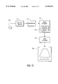
- FIG. 6 illustrates a combined B-mode and Doppler mode image
- FIG. 7 illustrates the alternate ultrasound firings required to produce the combined ultrasound image shown in FIG. 6;
- FIG. 8 illustrates how data produced from a forward and backward processing digital wall filter can be combined in order to fill in a gap in a Doppler echo signal
- FIG. 9 illustrates how data produced by a forward and backward processing digital wall filter are combined to minimize discontinuities
- FIG. 10 illustrates the limited number of echo data points that are typically obtained in color flow imaging.
- FIG. 11 illustrates the structure of a filter that increases the number of points for use in computing blood velocity using forward and backward processing according to the present invention.
- FIG. 12 is a block diagram of an ultrasound system that incorporates the forward/backward processing filters according to the present invention.
- FIG. 1 illustrates a conventional method of filtering digitized input data with a digital filter having a finite impulse response, h(k).
- h 1 1- ⁇
- h 2 ⁇
- h 3 ⁇ 2
- h 4 ⁇ 3
- ⁇ is less than one.
- the initial three outputs Y 0 , Y 1 and Y 2 are transient or erroneous because each coefficient in the impulse response is not multiplied by a valid input data sample. Once each valid input sample is paired with a coefficient of the impulse response, valid output data points Y 3 -Y 15 are produced.
- the number of transients produced depends on the number of filter coefficients in the impulse response.
- the filter arrangement shown in FIG. 1 is referred to as a "forward processing" filter because the input data is applied to the filter in the order it was received i.e., in chronological order.
- the present invention operates to produce at least two sets of output data wherein any transients in each set are produced in response to different input values. Outputs from each set are then combined to produce a complete set of output values with no transient or erroneous data.
- FIG. 2 illustrates one method of computing a set of output data values to be combined with a data set that is produced by a forward processing filter.
- the data is applied to a filter in a reverse chronological order. That is, instead of applying the first sample X 0 to the filter, the last input data sample, X 15 , is applied to the filter followed by other input samples in reverse chronological order.
- the first outputs of the filter Y' 15 , Y' 14 , Y' 13 are all transients because at least one filter coefficient is not paired with a valid input sample. However, once each coefficient of the impulse response is paired with the valid data sample, valid output data values Y' 12 -Y' 0 are produced.
- the effect of processing the data in the reverse chronological order is to create the transients at the end of the data set (when reordered from Y' 0 -Y' 15 ) rather than at the beginning of the data set as occurs in the forward processing filter shown in FIG. 1.
- a valid output sample is produced for each of the input data values.
- the filter arrangement shown in FIG. 2 is referred to as a "backward processing" filter.
- the disadvantage with the backward processing filter illustrated in FIG. 2 is that the entire set of input samples must be stored and reordered prior to filtering.
- the output values are calculated in reverse chronological order and therefore must be reordered prior to use.
- FIG. 3 An alternative embodiment of the backward processing filter is shown in FIG. 3.
- the output data produced is the same as the output data produced by the backward processing filter as shown in FIG. 2.
- the input data can be applied to the filter in the order it is received and the outputs are produced in the correct order.
- This approach is passable only for FIR filters. In the case of IIR filters, because of the infinite impulse response and whole filter structure, only the data can be reversed.
- FIG. 4 illustrates a block diagram of a filtering system used to process ultrasound data in accordance with the present invention.
- the filtering system utilizes a forward processing filter 10 that is connected in parallel with a backward processing filter 12.
- the forward processing filter 10 comprises a conventional FIR or IIR filter that receives a series of input data in a chronological order and produces a series of output data values Y 0 -Y 15 wherein the first few output values are erroneous or transient.
- the backward processing filter 12 operates to produce a series of output values Y' 0 -Y' 15 having transients that are produced in response to different input data samples than those that create the transients in the forward filter 10.
- a combiner 14 is therefore selected to receive the output data produced by either the forward processing filter 10 or the backward processing filter 12 in order to produce a complete data set without transients.
- FIG. 5 illustrates a block diagram of a combined forward and backward processing filter that produces a set of output data without transients.
- This embodiment is particularly useful for where the reserve filter is implemented as an IIR filter. If an FIR filter is used, it is easier to reverse the filter coefficients as discussed above.
- a forward processing path a set of N input samples is applied to a filter 22 that produces a set of output values with a number of transients created in response to a first number of input samples.
- the output values of the filter 22 are stored in a first in, first out (FIFO) buffer 24 having a length equal to twice the number of input samples supplied.
- the FIFO buffer 24 is used to insure that the output data produced by the filter 22 in the forward processing path is ready at the same time as the data produced in a backward processing path.
- the input data is supplied to a first in, last out (FILO) buffer 26 of length N.
- the FILO buffer 26 operates to reorder the data in a reverse chronological order.
- the reordered data is applied to a backward processing filter 28 that convolves the data with the same impulse response function as used in the forward filter 22.
- the output of the backward filter 28 is supplied to a first in, last out (FILO) buffer 30 that reorders the output data in the proper chronological order.
- Data from the buffers 24 and 30 are supplied to a combiner circuit 32 which operates to select either the data produced in the forward or backward data processing path.
- the combiner 32 operates to select nontransient data from each data processing path such that an entire set of output data without transients is produced.
- the first N-T samples will be created with the backward channel where N is the length of the FILO buffer 26 and T is the number of transients produced.
- the remaining output samples, y(k) where k>(N-(T-1)) will be generated by the forward filter.
- One specific application of the present invention is to reduce the discontinuities in a Doppler ultrasound signal due to alternate mode firings.
- the present invention can be used with color flow imaging to increase the number of data points used to estimate the speed of blood flow.
- FIG. 6 illustrates a typical combined B-mode and Doppler mode ultrasound image.
- the combined image 40 includes a B-mode image 42 that allows a physician to view the structure of the internal body tissue of a patient under examination.
- the B-mode image 42 is shown as a two-dimensional, black and white image.
- a range gate 44 is produced on the display.
- the range gate 44 is aligned with the direction at which the ultrasound beam is directed into the patient and includes a pair of markers 46 that determine the depth within the tissue from which the Doppler information is to be obtained.
- a Doppler image 48 comprising a graph of the velocity of the blood contained at the depth specified by the markers on the range gate versus time is shown on the composite image 40. Therefore, by viewing the B-mode and Doppler images, the physician is able to diagnose the patient under examination.
- the Doppler signals may be applied to a pair of speakers (not shown) so that a sonographer can "hear" the direction and velocity of the blood flow.
- FIG. 7 illustrates a typical pattern of ultrasound firings and how they correlate with the image of the Doppler signals.
- the Doppler display 48 that depicts the velocity of the tissue versus time is computed by firing a number of Doppler pulses 50 into the patient. The Doppler data created in response to these pulses is calculated and either graphed or played for the sonographer. When it is time to refresh the B-mode display, the Doppler pulses end and a series of B-mode pulses 54 are fired. Because no Doppler information is being obtained during this time, the Doppler display 48 includes a gap 52 that is visible on the display or audible if the Doppler signals are played as audio signals for the sonographer.
- the echo data created in a response to the Doppler mode firings are filtered with a digital wall filter that operates to remove the low-frequency, high-intensity signals from the echo signals received.
- the wall filter is an infinite impulse response (IIR) filter, the designs of which are considered well-known and therefore will not be discussed further except as it relates to the present invention.
- IIR infinite impulse response
- Most digital wall filters require a number of input samples to be supplied to the filter before they achieve their steady-state response.
- This extra gap 56 serves to further increase the length of the gap 52 in the Doppler display 48.
- the present invention uses a forward and backward processing digital wall filter wherein a portion of the filtered echo data produced by each filter is combined to produce an output data set with no transients.
- the transient data points can be replaced with the outputs of the backward processing digital wall filter that are produced in response to the first 100 echo data samples. Because a valid output value is obtained for each input sample, the extra gap 56 shown in FIG. 7 is eliminated.
- FIG. 8 illustrates the preferred way of combining data from the backward and forward processing filters.
- the point at which the data from the backward processing digital filter is joined to the output data from the forward processing digital filter should be made at a point 58 where the backward processing filter has an output that is near zero with a positive or negative slope and at a point 59 where the output data from the forward processing filter has a value near zero and an opposite slope.
- the output values of the filters may be proportionally combined over a number of outputs. For example, an output may be generated that utilizes 90% of the backward processing filter and 10% of the forward processing filter followed by 85% of the backward processing filter and 15% of the forward processing filter, etc., in order to smoothly blend the two filter outputs.
- FIG. 9 illustrates how the outputs of the forward and backward processing filters can be combined in order to create data that can be used to fill in the gap that is created when the ultrasound imaging system is operating in a non-Doppler mode.
- a graph 60 illustrates the outputs of the backward processing filter in response to a set of input echo data.
- a graph 62 illustrates the outputs of the forward processing filter created in response to the same set of input echo data.
- the present invention utilizes a number of the outputs of the backward processing filter for a time period "A" and concatenates the outputs with the outputs of the forward processing filter for a time period "B."
- the duration of the time period "A plus B" is equal to one cycle of the Doppler imaging plus the gap time when the ultrasound machine performs another type of imaging.
- this repeated data is relatively short compared to the length of the Doppler signal and does not seriously detract from the accuracy of the Doppler signal displayed on a monitor or played through speakers to the sonographer.
- the present invention is not limited to ultrasound systems that alternate between different imaging modes.
- the invention can be used in any environment wherein it is desirable to maximize the amount of data received from a digital filter that creates transients in response to the initial number of data samples applied.
- many ultrasound systems perform color mode imaging, where each point to be imaged in the body is subjected to a relatively short number (typically 8-16) of ultrasound pulses.
- the echo data, X 0 -X 7 created in response to these pulses is analyzed to determine a frequency shift between them. If the frequency is shifting, then the echo data is shown in a color that is representative of the velocity of the tissue. However, if no frequency shift is detected, the echo data is typically shown in black and white.
- X 0 -X 7 created in a response to the short number of ultrasound pulses can be frequency-analyzed, it is applied to a digital wall filter that removes those echo signals created in response to moving tissue or artery walls.
- this wall filter is a digital filter that produces transients in response to the first few data points. If conventional filtering is used, the number of valid data points created is reduced by the number of transients produced by the filter.
- the present invention supplies the echo data to a forward and backward processing filter.
- the forward and backward filters each produce transients in response to different input samples. Therefore, outputs from each of the filters can be combined to produce a data set having no transients.
- FIG. 11 illustrates how a forward and backward processing filter can be constructed in order to increase the number of valid output data points from a limited number of input samples.
- the filter can be constructed using a matrix 100 wherein one half of the matrix represents the backward processing filter 102 and the other half of the matrix represents the forward processing filter 104.
- Each matrix contains the same impulse response coefficients.
- the coefficients for the backward processing filter are preferably inverted compared to the forward processing filter. That is, the first row of the matrix for the forward processing filter contains the coefficients h 4 , h 3 , h 2 , h 1 0, 0, 0, while the first row of the backward processing filters contains the filter coefficients h 1 , h 2 , h 3 , h 4 , 0, 0, 0.
- the matrix 100 scales the set of input data X 1 , X 2 , . . . X 7 to produce a series of output values Y 1 , Y 2 , Y 3 , Y 4 , Y' 4 , Y 5 , Y 6 , Y 7 .
- the output values Y 4 and Y' 4 are similar in that the largest coefficient of the impulse response is multiplied by the same input data value.
- a first lag auto-correlation for the echo signals is determined between the output data pairs Y 1 , Y* 2 ; Y 2 , Y* 3 ; Y 3 , Y* 4 ; Y 4 , Y* 5 ; Y 5 , Y* 6 and Y 6 , Y* 7 to avoid the artifacts mentioned in the Thorp et al. article discussed above.
- Only pulse pairs from the backward processing filter 102, or the forward processing filter 104 are used. No analysis is performed on the pairs Y 4 and Y 4 that cross the boundary between output values produced for the backward processing filter and those produced by the forward processing filter.
- the number of valid output data samples is increased to equal the number of input data samples. Therefore, a more accurate determination of the flow of a particular point in the body can be computed.
- FIG. 12 is a block diagram of an ultrasound system that includes the forward/backward processing filters described above.
- An ultrasound transducer 110 transmits ultrasound signals into the patient and receives echo signals from tissue or moving blood flow.
- the ultrasound transducer is controlled by a transmit/receive block 112 that either supplies the ultrasound signals to be transmitted into the patient to the transducer and receives the electronic echo signals created by the transducer in response to received echoes.
- the electronic echo signals received by the transmit/receive block 112 are supplied to a beam former 114 where they are spatially processed to produce echo data having a magnitude corresponding to the strength of the echo signals at each position in the body. Echo data produced by the beam former 114 is supplied to an image processor 116 that performs a variety of digital processing techniques.
- the image processor 116 includes the forward and backward processing wall filters 118 described above.
- Valid output data produced by the image processor is supplied to a video processor 120 that converts the data into a format that can be displayed for a user.
- the output of the video processor 120 supplies a video monitor 122 with signals that can be displayed for a physician or sonographer.
Abstract
Description
Claims (9)
Priority Applications (1)
| Application Number | Priority Date | Filing Date | Title |
|---|---|---|---|
| US09/212,015 US6110113A (en) | 1998-12-15 | 1998-12-15 | Method and apparatus for removing transients and gaps from ultrasound echo signals |
Applications Claiming Priority (1)
| Application Number | Priority Date | Filing Date | Title |
|---|---|---|---|
| US09/212,015 US6110113A (en) | 1998-12-15 | 1998-12-15 | Method and apparatus for removing transients and gaps from ultrasound echo signals |
Publications (1)
| Publication Number | Publication Date |
|---|---|
| US6110113A true US6110113A (en) | 2000-08-29 |
Family
ID=22789204
Family Applications (1)
| Application Number | Title | Priority Date | Filing Date |
|---|---|---|---|
| US09/212,015 Expired - Lifetime US6110113A (en) | 1998-12-15 | 1998-12-15 | Method and apparatus for removing transients and gaps from ultrasound echo signals |
Country Status (1)
| Country | Link |
|---|---|
| US (1) | US6110113A (en) |
Cited By (9)
| Publication number | Priority date | Publication date | Assignee | Title |
|---|---|---|---|---|
| US20050272995A1 (en) * | 2000-03-08 | 2005-12-08 | Prince Martin R | Method for generating a gating signal for an MRI system using an ultrasonic detector |
| US20090012398A1 (en) * | 2007-07-03 | 2009-01-08 | Shenzhen Mindray Bio-Medical Electronics Co., Ltd. | Method and apparatus for filling doppler signal gaps in ultrasound diagnostic imaging |
| US20090324047A1 (en) * | 2008-06-27 | 2009-12-31 | Jarisch Wolfram R | High efficiency computer tomography |
| US20100278413A1 (en) * | 2008-06-27 | 2010-11-04 | Jarisch Wolfram R | High efficiency computer tomography with optimized recursions |
| US20110118606A1 (en) * | 2009-11-16 | 2011-05-19 | Tae Yun Kim | Adaptively performing clutter filtering in an ultrasound system |
| CN102283681A (en) * | 2010-05-19 | 2011-12-21 | 株式会社东芝 | Ultrasonic diagnostic apparatus and ultrasonic diagnostic apparatus control method |
| WO2014004052A1 (en) * | 2012-06-29 | 2014-01-03 | Ge Medical Systems Global Technology Company, Llc | Ultrasound diagnostic apparatus and method for generating doppler spectrum signal |
| US10176813B2 (en) | 2015-04-17 | 2019-01-08 | Dolby Laboratories Licensing Corporation | Audio encoding and rendering with discontinuity compensation |
| CN110013274A (en) * | 2015-04-29 | 2019-07-16 | 深圳迈瑞生物医疗电子股份有限公司 | Display methods and ultrasonic image-forming system is imaged in supersonic blood |
Citations (8)
| Publication number | Priority date | Publication date | Assignee | Title |
|---|---|---|---|---|
| US5016641A (en) * | 1989-11-13 | 1991-05-21 | Advanced Technology Laboratories, Inc. | Spectral interpolation of ultrasound Doppler signal |
| US5249578A (en) * | 1992-09-15 | 1993-10-05 | Hewlett-Packard Company | Ultrasound imaging system using finite impulse response digital clutter filter with forward and reverse coefficients |
| US5419333A (en) * | 1993-06-08 | 1995-05-30 | Matsushita Electric Industrial Co., Ltd. | Ultrasonic doppler blood flow meter apparatus |
| US5476097A (en) * | 1994-10-13 | 1995-12-19 | Advanced Technology Laboratories, Inc. | Simultaneous ultrasonic imaging and Doppler display system |
| US5706817A (en) * | 1995-05-08 | 1998-01-13 | Medison Co., Ltd. | Filtering method for ultrasonic color doppler imaging system |
| US5823964A (en) * | 1996-12-30 | 1998-10-20 | Siemens Medical Systems, Inc. | Ultrasound doppler wall filter |
| US5876341A (en) * | 1997-06-30 | 1999-03-02 | Siemens Medical Systems, Inc. | Removing beam interleave effect on doppler spectrum in ultrasound imaging |
| US5913824A (en) * | 1996-10-31 | 1999-06-22 | Kabushiki Kaisha Toshiba | Ultrasound diagnostic apparatus |
-
1998
- 1998-12-15 US US09/212,015 patent/US6110113A/en not_active Expired - Lifetime
Patent Citations (8)
| Publication number | Priority date | Publication date | Assignee | Title |
|---|---|---|---|---|
| US5016641A (en) * | 1989-11-13 | 1991-05-21 | Advanced Technology Laboratories, Inc. | Spectral interpolation of ultrasound Doppler signal |
| US5249578A (en) * | 1992-09-15 | 1993-10-05 | Hewlett-Packard Company | Ultrasound imaging system using finite impulse response digital clutter filter with forward and reverse coefficients |
| US5419333A (en) * | 1993-06-08 | 1995-05-30 | Matsushita Electric Industrial Co., Ltd. | Ultrasonic doppler blood flow meter apparatus |
| US5476097A (en) * | 1994-10-13 | 1995-12-19 | Advanced Technology Laboratories, Inc. | Simultaneous ultrasonic imaging and Doppler display system |
| US5706817A (en) * | 1995-05-08 | 1998-01-13 | Medison Co., Ltd. | Filtering method for ultrasonic color doppler imaging system |
| US5913824A (en) * | 1996-10-31 | 1999-06-22 | Kabushiki Kaisha Toshiba | Ultrasound diagnostic apparatus |
| US5823964A (en) * | 1996-12-30 | 1998-10-20 | Siemens Medical Systems, Inc. | Ultrasound doppler wall filter |
| US5876341A (en) * | 1997-06-30 | 1999-03-02 | Siemens Medical Systems, Inc. | Removing beam interleave effect on doppler spectrum in ultrasound imaging |
Cited By (19)
| Publication number | Priority date | Publication date | Assignee | Title |
|---|---|---|---|---|
| US20050272995A1 (en) * | 2000-03-08 | 2005-12-08 | Prince Martin R | Method for generating a gating signal for an MRI system using an ultrasonic detector |
| US8206302B2 (en) * | 2007-07-03 | 2012-06-26 | Shenzhen Mindray Bio-Medical Electronics Co., Ltd. | Method and apparatus for filling doppler signal gaps in ultrasound diagnostic imaging |
| US20090012398A1 (en) * | 2007-07-03 | 2009-01-08 | Shenzhen Mindray Bio-Medical Electronics Co., Ltd. | Method and apparatus for filling doppler signal gaps in ultrasound diagnostic imaging |
| CN101336830B (en) * | 2007-07-03 | 2012-07-04 | 深圳迈瑞生物医疗电子股份有限公司 | Orthogonal Doppler signal gap filling method and device for ultrasonic dignosis imaging |
| US20100278413A1 (en) * | 2008-06-27 | 2010-11-04 | Jarisch Wolfram R | High efficiency computer tomography with optimized recursions |
| US20090324047A1 (en) * | 2008-06-27 | 2009-12-31 | Jarisch Wolfram R | High efficiency computer tomography |
| US8660328B2 (en) | 2008-06-27 | 2014-02-25 | Wolfram R. JARISCH | High efficiency computer tomography |
| US8660330B2 (en) * | 2008-06-27 | 2014-02-25 | Wolfram Jarisch | High efficiency computed tomography with optimized recursions |
| US20110118606A1 (en) * | 2009-11-16 | 2011-05-19 | Tae Yun Kim | Adaptively performing clutter filtering in an ultrasound system |
| US8684934B2 (en) * | 2009-11-16 | 2014-04-01 | Samsung Medison Co., Ltd. | Adaptively performing clutter filtering in an ultrasound system |
| CN102283681A (en) * | 2010-05-19 | 2011-12-21 | 株式会社东芝 | Ultrasonic diagnostic apparatus and ultrasonic diagnostic apparatus control method |
| US9538990B2 (en) | 2010-05-19 | 2017-01-10 | Toshiba Medical Systems Corporation | Ultrasonic diagnostic apparatus and ultrasonic diagnostic apparatus control method |
| TWI555514B (en) * | 2010-07-16 | 2016-11-01 | 沃爾夫藍R 杰利奇 | System, workstation and method for high efficiency computed tomography with optimized recursions |
| WO2014004052A1 (en) * | 2012-06-29 | 2014-01-03 | Ge Medical Systems Global Technology Company, Llc | Ultrasound diagnostic apparatus and method for generating doppler spectrum signal |
| CN104412124A (en) * | 2012-06-29 | 2015-03-11 | Ge医疗系统环球技术有限公司 | Ultrasound diagnostic apparatus and method for generating doppler spectrum signal |
| CN104412124B (en) * | 2012-06-29 | 2017-04-12 | Ge医疗系统环球技术有限公司 | Ultrasound diagnostic apparatus and method for generating doppler spectrum signal |
| US10176813B2 (en) | 2015-04-17 | 2019-01-08 | Dolby Laboratories Licensing Corporation | Audio encoding and rendering with discontinuity compensation |
| CN110013274A (en) * | 2015-04-29 | 2019-07-16 | 深圳迈瑞生物医疗电子股份有限公司 | Display methods and ultrasonic image-forming system is imaged in supersonic blood |
| CN110013274B (en) * | 2015-04-29 | 2022-04-22 | 深圳迈瑞生物医疗电子股份有限公司 | Ultrasonic blood flow imaging display method and ultrasonic imaging system |
Similar Documents
| Publication | Publication Date | Title |
|---|---|---|
| US5014710A (en) | Steered linear color doppler imaging | |
| US5165413A (en) | Steered linear color doppler imaging | |
| US5409007A (en) | Filter to reduce speckle artifact in ultrasound imaging | |
| EP1826587A2 (en) | Ultrasonic diagnostic apparatus and ultrasonic diagnostic method | |
| US6814703B2 (en) | Apparatus and method for ultrasonic diagnostic imaging using a contrast medium | |
| KR100372135B1 (en) | System and method for providing variable ultrasound analyses in a post-storage mode | |
| US5891039A (en) | Ultrasonic echography system including sequencing means for the examination of arteries | |
| US5735797A (en) | Method and apparatus for combining topographic flow power imagery with a B-mode anatomical imagery | |
| EP1354556B1 (en) | Ultrasonic apparatus and method for measuring the velocities of human tissues using the doppler effects | |
| US6110113A (en) | Method and apparatus for removing transients and gaps from ultrasound echo signals | |
| KR100232257B1 (en) | Ultrasound color doppler imaging system for minimizing transient response to a clutter signal | |
| Lovstakken et al. | Blood flow imaging-a new real-time, flow imaging technique | |
| US5865752A (en) | Method and apparatus for ultrasound imaging using normalized difference between successive frames | |
| US20070073152A1 (en) | Systems and methods for acquiring images simultaneously | |
| JPS6111659A (en) | Ultrasonic insepction device | |
| US5718230A (en) | Method and apparatus for creating ultrasound images using a reduced number of transmit beam lines | |
| US5058593A (en) | Apparatus for processing and displaying ultrasonic data | |
| JPH078492A (en) | Ultrasonic diagnostic device | |
| CN100403991C (en) | Ultrasound diagnosis apparatus operable in doppler mode | |
| JP2931707B2 (en) | Ultrasound diagnostic equipment | |
| JP3188394B2 (en) | Filtering method and filter circuit for ultrasonic color Doppler imaging system | |
| JP3000823B2 (en) | Ultrasound Doppler blood flow meter | |
| US5588433A (en) | Ultrasonic diagnostic apparatus | |
| JP2639391B2 (en) | Fluid map image forming device | |
| US7749166B2 (en) | System and method for filtering in imaging systems |
Legal Events
| Date | Code | Title | Description |
|---|---|---|---|
| AS | Assignment |
Owner name: SIEMENS MEDICAL SYSTEMS, INC., NEW JERSEY Free format text: ASSIGNMENT OF ASSIGNORS INTEREST;ASSIGNORS:BANJANIN, ZORAN;YAO, LIN-XIN;REEL/FRAME:010994/0318 Effective date: 20000619 |
|
| STCF | Information on status: patent grant |
Free format text: PATENTED CASE |
|
| FEPP | Fee payment procedure |
Free format text: PAT HOLDER NO LONGER CLAIMS SMALL ENTITY STATUS, ENTITY STATUS SET TO UNDISCOUNTED (ORIGINAL EVENT CODE: STOL); ENTITY STATUS OF PATENT OWNER: LARGE ENTITY |
|
| REFU | Refund |
Free format text: REFUND - SURCHARGE, PETITION TO ACCEPT PYMT AFTER EXP, UNINTENTIONAL (ORIGINAL EVENT CODE: R2551); ENTITY STATUS OF PATENT OWNER: LARGE ENTITY |
|
| FPAY | Fee payment |
Year of fee payment: 4 |
|
| FPAY | Fee payment |
Year of fee payment: 8 |
|
| AS | Assignment |
Owner name: SIEMENS MEDICAL SOLUTIONS USA, INC.,PENNSYLVANIA Free format text: CHANGE OF NAME;ASSIGNOR:SIEMENS MEDICAL SYSTEMS, INC.;REEL/FRAME:024529/0474 Effective date: 20010801 |
|
| FPAY | Fee payment |
Year of fee payment: 12 |