US6112267A - Hierarchical ring buffers for buffering data between processor and I/O device permitting data writes by processor and data reads by I/O device simultaneously directed at different buffers at different levels - Google Patents
Hierarchical ring buffers for buffering data between processor and I/O device permitting data writes by processor and data reads by I/O device simultaneously directed at different buffers at different levels Download PDFInfo
- Publication number
- US6112267A US6112267A US09/086,134 US8613498A US6112267A US 6112267 A US6112267 A US 6112267A US 8613498 A US8613498 A US 8613498A US 6112267 A US6112267 A US 6112267A
- Authority
- US
- United States
- Prior art keywords
- buffer
- processor
- memory
- data
- buffers
- Prior art date
- Legal status (The legal status is an assumption and is not a legal conclusion. Google has not performed a legal analysis and makes no representation as to the accuracy of the status listed.)
- Expired - Lifetime
Links
- 239000000872 buffer Substances 0.000 title claims abstract description 431
- 230000003139 buffering effect Effects 0.000 title claims abstract description 7
- 238000000034 method Methods 0.000 claims abstract description 44
- 238000010586 diagram Methods 0.000 description 10
- 238000004891 communication Methods 0.000 description 9
- 238000012360 testing method Methods 0.000 description 8
- 230000005540 biological transmission Effects 0.000 description 6
- 230000006870 function Effects 0.000 description 5
- 238000013459 approach Methods 0.000 description 4
- 230000008901 benefit Effects 0.000 description 4
- 239000012464 large buffer Substances 0.000 description 4
- 230000008569 process Effects 0.000 description 4
- 238000013461 design Methods 0.000 description 3
- 238000012545 processing Methods 0.000 description 3
- 239000007853 buffer solution Substances 0.000 description 2
- 230000008867 communication pathway Effects 0.000 description 2
- 230000001404 mediated effect Effects 0.000 description 2
- 238000012986 modification Methods 0.000 description 2
- 230000004048 modification Effects 0.000 description 2
- 230000003068 static effect Effects 0.000 description 2
- 238000012546 transfer Methods 0.000 description 2
- 230000001174 ascending effect Effects 0.000 description 1
- 230000008859 change Effects 0.000 description 1
- 238000013479 data entry Methods 0.000 description 1
- 230000009849 deactivation Effects 0.000 description 1
- 230000000694 effects Effects 0.000 description 1
- 238000005516 engineering process Methods 0.000 description 1
- 238000011423 initialization method Methods 0.000 description 1
- 230000007246 mechanism Effects 0.000 description 1
- 230000037361 pathway Effects 0.000 description 1
- 230000002093 peripheral effect Effects 0.000 description 1
- 230000009467 reduction Effects 0.000 description 1
- 239000000523 sample Substances 0.000 description 1
- 239000000243 solution Substances 0.000 description 1
Images


Classifications
-
- G—PHYSICS
- G06—COMPUTING; CALCULATING OR COUNTING
- G06F—ELECTRIC DIGITAL DATA PROCESSING
- G06F12/00—Accessing, addressing or allocating within memory systems or architectures
- G06F12/02—Addressing or allocation; Relocation
- G06F12/08—Addressing or allocation; Relocation in hierarchically structured memory systems, e.g. virtual memory systems
-
- G—PHYSICS
- G06—COMPUTING; CALCULATING OR COUNTING
- G06F—ELECTRIC DIGITAL DATA PROCESSING
- G06F5/00—Methods or arrangements for data conversion without changing the order or content of the data handled
- G06F5/06—Methods or arrangements for data conversion without changing the order or content of the data handled for changing the speed of data flow, i.e. speed regularising or timing, e.g. delay lines, FIFO buffers; over- or underrun control therefor
- G06F5/065—Partitioned buffers, e.g. allowing multiple independent queues, bidirectional FIFO's
Definitions
- This invention relates generally to computer memory management and, more particularly, to optimizing memory utilization in the communication between a processor and an input/output device.
- a computer system typically includes several essential components: a processor, memory, and input and output (“I/O") devices, e.g., printers, graphics devices, or network interfaces.
- I/O input and output
- computer memory is usually arranged in a hierarchy.
- the hierarchy extends from memory placed closest to the processor, typically, smallest, fastest, and most expensive, to that furthest from the processor, typically, largest, slowest, and cheapest.
- Conventional memory components in ascending order of the hierarchy generally include processor cache (“on-chip” cache), static random access memory (static "RAM” or “SRAM”) cache (“off-chip” cache), main memory dynamic random access memory (dynamic "RAM” or “DRAM”), and disks.
- processor cache on-chip
- static random access memory static random access memory
- SRAM static random access memory
- DRAM main memory dynamic random access memory
- Communication pathways between the computer system's components comprise bus lines that carry timing, address, data, and control signals.
- the flow of data on these pathways between a processor and an I/O device presents two fundamental problems in computer system design. Processors often produce data at a quicker rate than can be accepted by a device while, conversely, devices often spend idle time awaiting a processor occupied with computations. Without attempts to mitigate these situations, computer system performance suffers. Solutions to these problems have been implemented through the use of memory buffers. A buffer is a specifically allocated portion of memory.
- a memory buffer can provide a temporary data repository to mediate the flow of data between a processor and an I/O device.
- the buffer permits the processor to continue producing data.
- the buffer may permit the I/O device to continue consuming previously produced data.
- One I/O device of particular susceptibility to highly variable data rates, is a graphics device.
- graphics device In general, during operation of a graphics device, large amounts of graphics data are converted by the graphics device to pixel data according to complex commands and data provided by the processor. If the commands are not received in time, the graphics device is idle. Brief periods with very high data generation and transmission intermix with longer periods of relatively low rates of data generation and transmission. These brief periods can generate and transmit data at a rate beyond the processing rate of the graphics device.
- the processor With insufficient buffering for this data, the processor will stall when the buffer fills. The processor must then wait for the graphics device to read and process data in the buffer.
- the converse problem can occur: the graphics device awaits data or commands from a compute-bound processor, i.e. the processor has stopped generating data and commands while engaged in other lengthy computations. At such times, the graphics device will sit idly awaiting new data and commands from the processor. In this case, a small buffer guarantees that the graphics device will sit idle for nearly the same length of time that the processor is not generating new data for the graphics device.
- a larger buffer may allow the graphics device to operate for long periods of time--perhaps the entire time--while the processor is not generating new data for the graphics device, when the buffer contains a relatively large amount of previously generated data.
- the processor can switch contexts and start executing a different application. While this may cause other applications to execute faster, this provides no increase in performance of the graphics device. Indeed, context switching can decrease graphics performance due to the large overheads involved in a context switch, which can result in the graphics device remaining inefficiently idle while the processor executes another application.
- the most efficient operation of a processor and a graphics device may require a buffer large enough to store millions of bytes of data.
- a buffer large enough to store millions of bytes of data.
- the location of the buffer may be at a level that allows the processor to send data to the buffer at a highest possible rate.
- PIO Direct Programmed I/O
- Some computer system designs achieve the highest possible processor performance and highest possible data transmission rate through the use of PIO.
- This approach requires the presence of a large buffer at the graphics device.
- the graphics device generally possesses a computational graphics IC as one of its component parts.
- current technology makes it impractical to include a large buffer, e.g., one with several hundred to thousands of kilobytes, directly within the graphics IC.
- Off-chip RAM located in the graphics device can support such a large buffer, but at an undesirable cost.
- such an RAM is usually single-ported, i.e., the RAM can either receive or transmit data at any given instant in time.
- the off-chip RAM must have a sufficient data transmission rate to multiplex, i.e., switch, between receiving new data from the processor, and transmitting stored data to the graphics device. Though a single RAM might be capable of storing enough bytes, the RAM may not have enough pin bandwidth, meaning data transmission rate capacity. Thus multiplexing may force the use of two or more RAM chips, further increasing the cost of the graphics device.
- the graphics IC must be designed with extra pin connections for reading and writing the RAM buffer; this too increases the cost of the graphics device.
- an on-chip write buffer is typically designed to retire modified on-chip cache lines to a high-bandwidth off-chip cache ("level 2 cache"). Therefore, on-chip buffers are fairly small, on the order of 128 to 256 bytes. When confronted with a high-bandwidth stream of writes to a relatively low-bandwidth bus, such an on-chip write buffer can easily fill up, stalling the processor while the graphics device reads the write buffer at a slower rate.
- DMA Direct Memory Access
- the processor's main memory has fairly low bandwidth compared to the caches. If the processor spends an interval of time computing a large data set and quickly writes the entire set to the DMA ring buffer in a burst of activity, then the processor fills the write buffer faster than main memory can consume the write buffer. Consequently, the processor stalls and performance degrades.
- Latency and bandwidth largely influence the performance of many software programs. For such programs, chances in processor clock speed have a minor performance impact, but changes in memory bandwidth and latency have a large performance impact. Where memory band width is insufficient, the increased memory traffic required for a DMA ring buffer can substantially decrease system performance.
- the processor sequentially writes all of the data for a variable length command, then goes back and non-sequentially writes the length count. Often, these variable-length commands are short enough to fit in the processor's write buffer. This allows the processor's write buffer to reorder the non-sequential length count writes into sequential writes to the memory system. With deactivation of reordering for uncached memory, the non-sequential writes require more transactions with the memory system, more DRAM preeharge and row-activation (page miss) cycles, and take up more space in the write buffer for the same amount of data. This reduces performance.
- the cache can retire data from the write buffer at a much higher rate than can a buffer in main memory. This reduces instances of a full write buffer and substantially reduces traffic to main memory.
- the writes can be reordered in the cache and the write buffer.
- cache trashing I/O bus bandwidth reductions, and validating reads.
- Cache trashing occurs when the processor writes to a ring buffer in cache; the writes "pollute" the caches by overwriting useful data with dirty ring buffer data that the processor will never again access. Worse still, the larger the ring buffer, the more cache pollution occurs. This leads to more frequent processor stalls as the processor refetches useful, evicted data back into the caches.
- the ring buffer must reside in a processor's on-chip cache, which may be too small, or in main memory, which eliminates the other advantages of using a cache.
- the invention provides an apparatus and method for enhanced processor to I/O device data communication.
- the invention makes use of hierarchical memory buffers to dynamically direct the data flow from the processor, through the buffers, to the I/O device.
- the invention permits data writes by the processor and data reads by the I/O device to be simultaneously directed at different buffers located at different levels in the memory hierarchy.
- the invention optimizes use of memory of different levels in the memory hierarchy as the need for buffer space dynamically varies during computer system operation.
- the use of multiple buffers and the dynamic switching between buffers enhances the flow of data from the processor, via the buffers, to the I/O device.
- the switching method permits use of higher bandwidth cache-based buffers with switches to a main memory buffer when the need for a larger buffer arises.
- the invention permits the relatively continuous flow of software produced data to be maintained while supporting the very high speed hardware mediated DMA reads of a graphics device or similar device. In the example instance of a graphics device, the invention provides a computer system with greatly improved graphics output performance
- the apparatus and method buffer data transmitted by a processor and received by an I/O device via a memory and buses.
- the memory is arranged at a plurality of levels, a lower level of the memory operating faster than a higher level of the memory.
- a plurality of buffers are allocated at different levels of the memory and available buffers at a lowest possible level of the memory are preferentially selected as write buffers to store data transmitted by the processor.
- the apparatus includes a first level of the memory arranged on an integrated circuit with the processor, a second level of the memory arranged in an off-chip cache, and a third level of the memory arranged in a dynamic random access memory.
- Read buffers are selected to store data to be received by the I/O device.
- a selection register located in the I/O device indicates the selected read buffer.
- Stored control values indicate the order for selecting the read buffers, and the values are used by the processor to select the write buffer.
- Control values are stored in hardware sets of registers located in the I/O device and in a software-based set of registers located in the dynamic random access memory.
- the plurality of buffers can be configured as ring buffers and the control values can be configured to include a head pointer, a tail pointer, a length, and a base address associated with each of the plurality of buffers.
- the processor by comparing the head pointers and the tail pointers, selects the write buffer. When a current write buffer is full, an available buffer at a next higher level of memory is selected as the write buffer. If the current write buffer has fewer memory addresses with stored data than a predetermined number of memory addresses and if a buffer at a next lower level of memory is empty, the buffer at the next lower level of memory is selected as the write buffer.
- FIG. 1a is a block diagram of a computer system including the apparatus of the invention
- FIG. 1b is a block diagram including primary components of an apparatus according to the invention: a processor; a graphics device; ring buffers located at different levels of the memory hierarchy; sets of registers associated with the buffers; and a selection register for identification of a read buffer;
- FIG. 2a is a block diagram of the sets of registers in the graphics device associated with the ring buffers
- FIG. 2b is a block diagram of the software-based set of registers
- FIGS. 3a-3l are a series of block diagrams depicting the structure and function of three ring buffers according to an alternative embodiment of the invention.
- FIG. 4 is a flow diagram of a method of operation of the apparatus
- FIG. 5 is a flow chart of steps of a method for reading data from the ring buffers by the graphics device and for updating of the sets of registers by the graphics device;
- FIGS. 6a-6d are a flow chart of steps for writing data to the ring buffers by the processor and for updating of the sets of registers by the processor.
- FIG. 1a shows a computer system 100 that uses the invention.
- the computer system 100 comprises the following hardware components: a processor 300, for example a Digital Equipment Corporation 21164 Alpha processor; a small on-chip processor cache memory 310 ("level 1" or “L1” cache); a first ring buffer 312 small enough to fit in the on-chip cache 310; a larger, off-chip cache 400 ("board” or “L2” cache) in communication with the processor 300; a second ring buffer 412 small enough to fit in off-chip cache 400; main memory 200, typically DRAM; a third ring buffer 212 large enough so that the third ring buffer 212 primarily resides in main memory 200; an I/O device 700, for example a graphics device; a processor-memory bus 610 in communication with the main memory 200 and the processor 300; an I/O bus 630 in communication with the I/O device 700; and a bus controller chip set 500, for example a Peripheral Component Interconnect controller (“PCI" controller), in communication with the processor
- FIG. 1b schematically depicts communication pathways in the apparatus.
- the processor 300 communicates data to the ring buffers 312, 412, or 212 while the buffers communicate data to the graphics device 700.
- Both the processor 300 and the graphics device 700 are in communication with a first and a second hardware set of registers 720 and 730 and a selection register 710, the sets of registers 720 and 730 and the selection register 710 located in the graphics device 700.
- there is a software-based set of registers 320 (not depicted in FIG. 1b) located at and in communication with the processor 300.
- FIG. 2a depicts the structure of the sets of registers 720 and 730.
- the sets of registers 720 and 730 are preferably located on the graphics IC of the graphics device 700.
- the two sets of registers 720 and 730 have identical structure. The description given below for the set of registers 720 applies similarly to the set of registers 730.
- the set of registers 720 provides storage for a ring buffer base pointer 722, a ring buffer length 724, a head pointer 726, and a tail pointer 728.
- the head and tail pointers 726 and 728 may contain ring buffer addresses. Alternatively, the head and tail pointers 726 and 728 may provide the buffer addresses by storing indices to be added to the ring buffer base address.
- the base pointer 722 provides the base address of a ring buffer, for example ring buffer 312, while the length 724 provides the size of the ring buffer 312 in bytes, words, or some other convenient format.
- the tail pointer 728 identifies a buffer address which immediately follows the address of data last written by the processor 300 to, for example, ring buffer 312.
- the head pointer 726 similarly identifies a buffer address which immediately follows the address of data most recently read from the ring buffer 312 by the graphics device 700.
- the software-based set of registers 320 stores the same type of buffer descriptive data as the hardware sets of registers 720 and 730.
- the set of registers 730 describes the first, second, or third ring buffer, which may be the same as the ring buffer described by the set of registers 720, or a different ring buffer.
- the software-based set of registers 320 describes yet another ring buffer, for example ring buffer 212, as needed. Details of the functioning of the hardware sets of registers 720 and 730 and the software-based set of registers 320 are described below.
- FIG. 2a also depicts the selection register 710 located with the set of registers 720 and 730 of the graphics device.
- the selection register 710 comprises a single bit.
- the selection register 710 identifies the current or "active" set of registers for graphics device 700 reads, either the set of registers 720 or the set of registers 730, as discussed below.
- the selection register 710 can be said to hold a "ring active bit".
- the graphics device 700 uses the set of registers 720 to determine the location of the active ring buffer.
- the ring active bit of the selection register 710 has a logical value of 1
- the graphics device 700 uses the set of registers 730.
- the graphics device 700 always reads data from the presently active buffer, that is, from the buffer described by the active set of registers. It should be noted that inclusion of additional active bits in the selection register 710 would permit the use of additional sets of registers.
- FIGS. 3a through 31 depict the detailed structure and function of the three ring buffers 312, 412, and 212 respectively located in the processor's on-chip cache 310, off-chip cache buffer 400, and main memory 200.
- the functioning of the three ring buffers 312, 412, and 212 will be illustrated in detail below with reference to FIGS. 3a through 31.
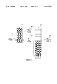
- FIG. 3a depicts a small first ring buffer 312, preferably located in the on-chip cache 310, and a relatively large second buffer 412, preferably located in the off-chip cache 400.
- the drawing is not to scale; in reality buffer 412 is about 16 to 128 times as large as buffer 312.
- the set of registers 720 describes buffer 312 and the set of registers 730 describes buffer 412.
- unshaded ring buffer locations contain data awaiting a read by the graphics device 700: shaded locations are available for data writes by the processor 300.
- the processor 300 and the graphics device 700 determine the quantity of data in a ring buffer by comparing the head pointer and the tail pointer in the corresponding set of registers 720 or 730.
- the processor 300 or the graphics device 700 can determine that the buffer 312 is empty. Conversely, a full buffer 312 is detected by determining that the head pointer 726 points to the address that immediately follows the address pointed to by the tail pointer 728.
- the size of the buffers 312, 412, and 212 is fixed during initialization of the apparatus. Given a particular application, these buffer sizes are chosen through experimentation to optimize performance.
- the processor 300 generates data to be eventually read by the graphics device 700.
- the bus controller 500 allows DMA reads and writes by the graphics device 700 to locations of the memory hierarchy.
- the controller 500 and the graphics device 700 cooperate to DMA read data from various locations in the memory hierarchy 200, 310, and 400 in accordance with values written by the processor 300 into set of registers 720 and 730.
- the processor 300 can directly read and write the sets of registers 720 and 730 that reside at the graphics device 700 through PIO transactions.
- the processor 300 can write data to buffers 312, 412 or 212. These are software writes to memory locations, that is, each item of data written as produced by executing software instructions.
- the graphics device 700 can read data from buffers 312, 412, or 212. These are DMA reads, that is, large quantities of data are read at a very high rate, e.g. 100 to 400 Mbytes/sec, in large continuous hardware mediated data transfers.
- FIG. 4 illustrates the overall method of operation of the apparatus.
- Steps 800 of FIG. 5 determine from which buffer 312, 412, or 212 to read data, and then these steps read data from the selected buffer.
- Steps 900 of FIGS. 6a-d select to which buffer 312, 412, or 212 the data are preferentially written, and then these steps write the data to the selected buffer.
- the dynamic and independent functioning of steps 900 and steps 800 permits the software writes and DMA reads to make use of buffers at different locations in the memory hierarchy; this mitigates the problems of small on-chip cache buffer 312 size, off-chip cache buffer 412 latency, and main memory buffer 212 bandwidth, as described above.
- FIGS. 5 and 6 give the detailed method of operation of the sets of registers 720 and 730 and buffers 312, 412, and 212 for the dynamic communication of data from the processor 300 to the graphics device 700 via buffers at different locations in the memory hierarchy.
- Data reads by the graphics device 700, as shown in FIG. 5, and data writes by the processor 300, as shown in FIG. 6, function separately. Data reads are described first.
- Step 810 the ring active bit of selection register 710 is set to "0" and buffer 312 is described by the active set of registers 720. Operation of the apparatus then enters a repeating portion of the flow diagram, Steps 820 to 870.
- Step 820 determines when the graphics device 700 is ready to read data. When ready, the graphics device 700 determines from which buffer to read using a DMA in Steps 830 to 850.
- Step 830 determines when data are present in the active buffer. If data are present in the active buffer, the operation proceeds to step 860. If the active buffer is empty, i.e.
- step 840 determines if there are data present in the inactive buffer. If the inactive buffer is also empty, then the method returns to step 830. If there are data in the inactive buffer, then the graphics device 700 inverts the ring active bit of the selection register 710 in step 850. The active buffer for data reads has been switched and the apparatus proceeds to step 860. In step 860, the graphics device 700 performs a DMA read from the active buffer, initially buffer 312, and in step 870 the graphics device 700 updates the head pointer in the active set of registers, initially head pointer 726. Finally, the method returns to step 820.
- the above method allows the use of two or more buffers by permitting the graphics device 700 to dynamically switch the buffer from which the graphics device 700 reads.
- the processor 300 determines which buffers, either 312, 412, or 212, that the set of registers 720 and 730 refer to at any given time. In this manner, the graphics device 700 can read in turn from buffers 312, 412, and 212 by always reading data from the active buffer.
- FIGS. 6a through 6d depicts the steps of a method for writing data by the processor 300.
- the one buffer 312, 412, or 212 presently used for writes is referred to as the "write" buffer. This will distinguish the present write buffer 312, 412, or 212, i.e. the "write” buffer, from the present read buffer 312, 412, or 212, i.e. the "active" buffer.
- FIG. 6a shows the operation of the apparatus of the invention when the processor 300 is trying to write to buffer 312.
- FIG. 6b shows the operation when the processor 300 is trying to write to buffer 412.
- FIG. 6c shows the operation when the processor 300 is trying to write to buffer 212, while updating one of the hardware tail pointers 728 or 738.
- FIG. 6d shows the operation when the processor 300 is trying to write to buffer 212, while updating the software-based tail pointer 328.
- the buffers 212, 312, and 412 can change their association with the sets of registers 720 and 730 via software control.
- the association of the set of registers 720 with the buffer 312 can be switched to an association of the set of registers 720 with the buffer 412.
- writes to a write buffer 312 can be tracked with the set of registers 720 or the set of registers 730.
- the set of registers 720 or 730 that is used to track writes is therefore called the "write" set of registers.
- the association must be tracked so that, as writes are made to the write buffer 312, 412, or 212, updates can be made to the write set of registers 720 or 730.
- Step 910 all buffers are empty.
- Software sets the write bit to 0, and initializes the write set of registers, in this case the set of registers 720, to describe ring buffer 312.
- the initialization method of Step 910 in detail is as follows:
- head pointer 726 and the tail pointer 728 are addresses, write the same physical address to the head pointer 726 and the tail pointer 728; if indices, write 0 into the head pointer 726 and the tail pointer 728.
- Step 920 determines whether the processor 300 has data to write. If not, then step 920 repeats until the processor 300 has data to write. If data are available for writes at step 920, then step 922 determines whether buffer 312 has space available for data writes by comparing the write head pointer, presently head pointer 726, with the write tail pointer, presently tail pointer 728. If space is available, i.e. buffer 312 is not full, then step 927 occurs next. In step 927, the processor 300 writes data to buffer 312 and subsequently optionally updates the write tail pointer, presently tail-pointer 728. Operation then returns to step 920.
- step 924 next occurs. This step determines whether buffer 412 is empty by comparing the non-write head and tail pointers. If buffer 412 is not empty at step 924, then the graphics device 700 is still executing commands from buffer 412, and the processor 300 has completely filled buffer 312. Thus both set of registers 720 and 730 are in use. In order to avoid stalling the processor 300, the method proceeds to step 928, where the software-based set of registers 320 is set up to describe buffer 212, after which the method proceeds to step 957.
- step 924 confirms the presence of an empty buffer 412, then the situation depicted in FIG. 3b exists, and step 925 next occurs.
- Step 925 inverts the write bit, so that software references to the set of registers will access the currently unused set of registers 720 or 730, and the write set of registers is initialized to describe buffer 412.
- the method proceeds to step 937. In this manner, the available buffer, in this case the buffer 412, at a lowest possible level of the memory is selected as the write buffer.
- FIG. 6b shows the method when the processor 300 is trying to write to the buffer 412. This is the most complicated portion of the method, because the data written may actually be stored into the buffer 412, then into the smaller buffer 312, or into the larger buffer 212.
- Step 930 tests whether the processor 300 has data to write, and step 930 repeats until the processor 300 does have data to write. The method then proceeds to step 932, which determines:
- buffer 412 has fewer memory addresses with stored data than a predetermined value "N".
- the value N is always less than the number of memory addresses of the buffer 312, i.e. the size of the buffer 312. N is fixed at a predetermined value to provide best performance for a particular application of the apparatus. A typical value of N for a graphics device 700 might be about 50-75% of the size of the buffer 312. If step 932 determines that the non-write set of registers is empty and that buffer 412 contains fewer memory addresses with stored data than the predetermined value N, then the situation depicted in FIG. 3e exists, and the method continues at step 933. Step 933 inverts the write bit, sets up the write set of registers to describe the buffer 312, then proceeds to step 927.
- step 934 tests whether the buffer 412 is full by comparing the write head pointer to the write tail pointer. If the buffer 412 is found not to be full at step 934, then step 937 occurs. Step 937 writes the data to the buffer 412, optionally updates the write tail pointer, and returns to step 930. If the buffer 412 is found to be full at step 934, then step 935 occurs. Step 935 determines whether the set of registers 720 or 730 not in use by software is empty. If so, then step 936 inverts the write bit, and sets up the write set of registers 720 or 730 to describe buffer 212, then proceeds to step 947. If step 935 determines that the non-write set of registers is still in use by hardware, then operation proceeds to step 938, which is identical to step 928. In this manner, the available buffer at the lowest possible level of the memory is selected as the write buffer.
- FIG. 6c shows operation when the processor 300 is trying to write to buffer 212, and the write set of registers describe buffer 212.
- Step 940 tests if there are data to write, and repeats until there are data, at which point operation proceeds to step 942.
- Step 942 determines whether the buffer 212 is full, and repeats until the buffer 212 is not full.
- step 944 tests whether the set of registers 720 or 730 not in use by software are also unused by the graphics device 700, and whether the buffer 212 has fewer memory addresses with stored data than a predetermined value "M"; if so, operation proceeds to step 945, otherwise to step 947.
- Step 945 is identical to step 925. Otherwise, the method proceeds to step 947 where writes occur to the buffer 212 and the write tail pointer is optionally updated, and the method then continues with step 940. In this manner, the available buffer at the lowest possible level of the memory is selected as the write buffer, in this case the buffer 212.
- FIG. 6d shows operation when the processor 300 is trying to write to buffer 212, and the sets of registers 720 and 730 are already devoted to describing the buffers 312 and 412. In this case, the processor 300 cannot update either of the tail pointers 728 or 738.
- Step 950 tests whether there are data to write, and repeats until there are data, at which point operation proceeds to step 952.
- Step 952 tests for emptiness the set of registers 720 or 730 least recently used by software. When empty, software can set up the unused set of registers 720 or 730 to notify the graphics device 300 about buffer 212, and operation proceeds to step 953.
- Step 953 inverts the write bit, and sets up the write set of registers 720 or 730 to describe buffer 212.
- step 955 which tests if buffer 212 is full. If so, then operation returns to step 952. Otherwise, operation proceeds to step 957, which writes the data to the buffer 212 and updates the software-based tail pointer 328, but does not update either the tail pointer 728 or the tail pointer 738. The method then returns to step 950. Again, in the above method, the available buffer at the lowest possible level of the memory is selected as the write buffer.
- tests for the number of memory addresses available for data writes in a buffer are made occasionally, rather than before each write of data to a buffer memory address.
- tail pointers should be periodically updated rather than after data is written to each buffer memory address.
- only one set of hardware registers is required.
- the single set of hardware registers need only include a single head register.
- a bit of data associated with the data stored at each buffer address can indicate whether or not the data at that address is to be read. Storing a switch command in the buffer can activate a switch to a new read buffer.
- FIGS. 3a through 3l illustrate the operation of the buffers 312, 412, and 212 and the sets of registers 720 and 730 and the selection register 710.
- the graphics device 700 reads data from active buffer 312.
- eight locations in buffer 312 store data.
- the tail pointer 728 is updated so that the tail pointer 728 continues to point to the next buffer address available for storing data. If the graphics device 700 is busy performing other functions, then the graphics device will temporarily cease to read data from the buffer 312.
- the buffer 312 fills with data written by the processor 300. At this time, the buffer 312 has one empty address. This address cannot be filled, for then the head and tail pointers 726 and 728 would be identical and the buffer would appear to be empty rather than full.
- a stall or context switch by the processor 300 is prevented by switching to an alternate, typically much larger, buffer.
- the processor 300 has written four data entries to the ring buffer 412 and updated the tail pointer 738 to indicate the next available buffer address. Note that while the write bit is now 1, so that the processor 300 updates the tail pointer 738, the ring active bit of the selection register 710 is still 0, so that the graphics device 700 still reads from the buffer 312 and updates the head pointer 726; the graphics device 700 must read all of the data from the buffer 312 before reading any data from the buffer 412. In this case, the graphics device 700 continues to process data. The graphics device 700 has yet to read another data item from the buffer 312, i.e. the header pointer 726 has yet to move.
- the processor 300 has written more data to the buffer 412.
- the graphics device 700 meanwhile has completed its other processing function and also has read data from the active buffer 312, emptying the buffer 312 of all data.
- the graphics device notes an empty buffer 312 due to the equivalence of the associated head and tail pointers 726 and 728.
- the graphics device 700 examines the ring buffer 412 for data by comparison of the head and the tail pointers 736 and 738, and by determining if the buffer length 734 is non-zero.
- the graphics device inverts the ring active bit of the selection register 710 to value "1" upon finding nonequivalent addresses in the head pointer 736 and the tail pointer 738, and a non-zero length in the register 724.
- the set of registers 730 becomes active.
- the graphics device 700 commences reading data from the buffer 412, starting at the address given by the head pointer 736.
- FIGS. 3e, 3f, and 3g depict how to switch to a smaller, though more efficient buffer.
- the graphics device 700 has read a large quantity of data from the buffer 412 while the processor 300 has written no additional data to the buffer 412.
- the processor 300 notes that the buffer 412 stores a small quantity of data relative to the possible buffer size of the more efficient buffer 312.
- An appropriate ratio, about 50-75% as described above, of the remaining entries in the buffer 412 to the buffer size in the buffer 312 determines that a switch of should be made for writes to the buffer 312.
- the ratio is chosen to ensure that little chance arises that the processor 300 will quickly fill buffer 312 with data before the graphics device 700 begins reading data from buffer 312.
- FIG. 3e the graphics device 700 has read a large quantity of data from the buffer 412 while the processor 300 has written no additional data to the buffer 412.
- the processor 300 notes that the buffer 412 stores a small quantity of data relative to the possible buffer size of the more efficient buffer 312.
- the processor begins writing new data to the buffer 312 and consistently updates the tail pointer 728.
- the graphics device 700 continues reading data from the active buffer 412.
- the graphics device 700 notes an empty buffer 412, again by comparing its associated the head and the tail pointers 736 and 738.
- the graphics device determines that the buffer 312 stores data by comparing the head pointer 726 and the tail pointer 728, and by noting whether the buffer length 724 is non-zero.
- the graphics devices again inverts the ring active bit of selection register 710 and the graphics device 700 begins to read data from the smaller, more efficient buffer 312.
- the write bit is not equal to the active bit 710, that is, the processor 300 is writing to one buffer while the graphics device 700 is reading data from a different buffer, then a more complicated situation can arise.
- the present write buffer receiving writes can become full before the graphics device 700 finishes reading all data in the active buffer.
- Use of a third buffer can permit data writes by the processor 300 to continue.
- FIG. 3h depicts a scenario in which the buffer 412 fills with data from the processor 300. Meanwhile, the graphics device 700 experiences a processing induced pause before the graphics device 700 resumes reading data from the full active buffer 312. While FIG. 3h depicts the full buffer 312, comments here generally also apply to a partially filled buffer 312.
- Various options are possible. For a very large buffer 412, one option is to permit the processor to switch contexts while awaiting the graphics device 700 to read a significant portion of this data.
- the buffer 412 resides at some intermediate location in the memory hierarchy, such as in off-chip cache 400, then best performance can be obtained by writing data to a third, larger, ring buffer 212.
- the method under discussion tracks the location of data and assures that the graphics device 700 reads data from the three buffers 312, 412, and 212 in a sequence in which the data were written by the processor 300. Note that, in the present scenario, data must be fully read from, first, the buffer 312, next, the buffer 412, and, lastly, the third buffer 212, before using just the two original buffers 312 and 412. In FIG. 3i, the buffer 412 has become full while the graphics device 700 continues reading data from the buffer 312.
- the processor 300 writes data to the buffer 212 while awaiting the emptying of the buffer 312.
- the processor 300 periodically checks the pointers in the set of registers 720 to determine the availability of the set of registers 720 by the emptying of the buffer 312.
- the processor 300 With use of the third buffer, treatment of the head pointer 726 and the tail pointer 728 for the buffer 312 changes.
- the head pointer 726 and the tail pointer 728 indirectly take part in tracking the location of data in both the buffer 312 and the temporary buffer 212.
- the processor 300 fills buffer 412 and begins writes to buffer 312, the processor 300 updates tail pointer 728 to track the location of the most recently entered data and next available data location.
- the set of registers 720 continues to refer to the buffer 312 as long as data remains in the buffer 312.
- the processor 300 uses the software-based set of registers 320 with the software-based tail pointer 328 to point to the next available memory location in the buffer 212.
- FIG. 3i depicts writes to the buffer 212 without up dates to the tail pointer 728.
- the graphics device 700 continues to read the remaining data in the buffer 312 before proceeding to read the data in the full buffer 412.
- the buffer 412 With the eventual emptying of the buffer 312, the buffer 412, described by set of registers 730, becomes the active buffer when the graphics device 700 changes the ring active bit of selection register 710 to a value of 1.
- the processor 300 notes the newly active buffer 412 and sets the set of registers 720 to the correct values for the buffer 212. This permits use of the set of registers 720 for control of data reads by the graphics device 700 from the buffer 212, after the graphics device 700 completes reading data from the buffer 412. In this manner, the graphics device 700 will correctly treat the buffer 212 as the active buffer after completion of data reads from the buffer 412. After the graphics device 700 reads all data in the buffer 212, the set of registers 720 can again refer to the buffer 312.
- writes by the processor 300 can fill the buffer 312 before the active buffer 412 is emptied of data by the graphics device 700.
- the processor 300 may then write data to the third, larger buffer, as discussed above and described in steps 900.
- writes can occur to the available space in the buffer 412.
- the available space in the buffer 412 resides between the addresses given by the tail pointer 728 and the head pointer 726. In either option, tracking of this newly written set of data occurs exactly as described above.
- FIG. 3k depicts the writing of data to unused space in the buffer 412, beginning and proceeding from the location given by the tail pointer 728.
- the set of registers 730 will be updated with the software-based head pointer 326 and the software-based tail pointer 328 by the processor 300 after the graphics device 700 completes its read of the preexisting data in the buffer 412.
- FIG. 31 depicts the updated head pointer 736 and the tail pointer 738 after the graphics device 700 has completed reading the preexisting data in the buffer 412 and has moved on to read data from the buffer 312.
Abstract
Description
Claims (27)
Priority Applications (1)
| Application Number | Priority Date | Filing Date | Title |
|---|---|---|---|
| US09/086,134 US6112267A (en) | 1998-05-28 | 1998-05-28 | Hierarchical ring buffers for buffering data between processor and I/O device permitting data writes by processor and data reads by I/O device simultaneously directed at different buffers at different levels |
Applications Claiming Priority (1)
| Application Number | Priority Date | Filing Date | Title |
|---|---|---|---|
| US09/086,134 US6112267A (en) | 1998-05-28 | 1998-05-28 | Hierarchical ring buffers for buffering data between processor and I/O device permitting data writes by processor and data reads by I/O device simultaneously directed at different buffers at different levels |
Publications (1)
| Publication Number | Publication Date |
|---|---|
| US6112267A true US6112267A (en) | 2000-08-29 |
Family
ID=22196504
Family Applications (1)
| Application Number | Title | Priority Date | Filing Date |
|---|---|---|---|
| US09/086,134 Expired - Lifetime US6112267A (en) | 1998-05-28 | 1998-05-28 | Hierarchical ring buffers for buffering data between processor and I/O device permitting data writes by processor and data reads by I/O device simultaneously directed at different buffers at different levels |
Country Status (1)
| Country | Link |
|---|---|
| US (1) | US6112267A (en) |
Cited By (41)
| Publication number | Priority date | Publication date | Assignee | Title |
|---|---|---|---|---|
| US6185640B1 (en) * | 1998-06-19 | 2001-02-06 | Philips Electronics North America Corporation | Minimal frame buffer manager allowing simultaneous read/write access by alternately filling and emptying a first and second buffer one packet at a time |
| US6272567B1 (en) * | 1998-11-24 | 2001-08-07 | Nexabit Networks, Inc. | System for interposing a multi-port internally cached DRAM in a control path for temporarily storing multicast start of packet data until such can be passed |
| US6363438B1 (en) * | 1999-02-03 | 2002-03-26 | Sun Microsystems, Inc. | Method of controlling DMA command buffer for holding sequence of DMA commands with head and tail pointers |
| US20020056006A1 (en) * | 2000-04-17 | 2002-05-09 | Mark Vange | Conductor gateway buffer prioritization |
| FR2823875A1 (en) * | 2001-01-27 | 2002-10-25 | Zarlink Semiconductor Ltd | DIRECT MEMORY ACCESS MANAGER FOR CIRCULAR STAMPS AND PROCESS FOR OPERATING A COMPUTER SYSTEM INCLUDING SUCH A REGISTER |
| US6473834B1 (en) * | 1999-12-22 | 2002-10-29 | Unisys | Method and apparatus for prevent stalling of cache reads during return of multiple data words |
| US6516363B1 (en) * | 1999-08-06 | 2003-02-04 | Micron Technology, Inc. | Output data path having selectable data rates |
| US20030200344A1 (en) * | 2002-04-19 | 2003-10-23 | Toshiyuki Fukushima | Vehicular communication device exchanging reception and transmission with external tool |
| US20040003187A1 (en) * | 2002-06-28 | 2004-01-01 | Microsoft Corporation | System and method for using virtual memory for redirecting auxilliary memory operations |
| US6675239B1 (en) * | 1999-10-05 | 2004-01-06 | Ati Technologies Inc. | Method and apparatus for providing commands to a command memory |
| US6694416B1 (en) | 1999-09-02 | 2004-02-17 | Micron Technology, Inc. | Double data rate scheme for data output |
| US6725298B1 (en) * | 1999-06-17 | 2004-04-20 | Nec Electronics Corporation | Method and system for filter-processing by ensuring a memory space for a ring-buffer in digital signal processor |
| US20040103245A1 (en) * | 2002-11-21 | 2004-05-27 | Hitachi Global Storage Technologies Nertherlands B.V. | Data storage apparatus and method for managing buffer memory |
| US20040111540A1 (en) * | 2002-12-10 | 2004-06-10 | Narad Charles E. | Configurably prefetching head-of-queue from ring buffers |
| US20040128425A1 (en) * | 2002-12-26 | 2004-07-01 | Micron Technology, Inc. | Using chip select to specify boot memory |
| US20060031603A1 (en) * | 2004-08-09 | 2006-02-09 | Bradfield Travis A | Multi-threaded/multi-issue DMA engine data transfer system |
| US20060195666A1 (en) * | 2005-02-25 | 2006-08-31 | Naoko Maruyama | Switching method of data replication mode |
| WO2007008324A2 (en) * | 2005-07-11 | 2007-01-18 | Atmel Corporation | High-speed interface for high-density flash with two levels of pipelined cache |
| US7196710B1 (en) * | 2000-08-23 | 2007-03-27 | Nintendo Co., Ltd. | Method and apparatus for buffering graphics data in a graphics system |
| US20070088792A1 (en) * | 2005-10-15 | 2007-04-19 | Piper Scott A | Hardware processing of commands within virtual client computing environment |
| US20070103475A1 (en) * | 2005-11-10 | 2007-05-10 | Via Technologies, Inc. | Interruptible GPU and method for processing multiple contexts and runlists |
| US20080005405A1 (en) * | 2006-06-05 | 2008-01-03 | Freescale Semiconductor, Inc. | Data communication flow control device and methods thereof |
| US20090204734A1 (en) * | 2008-02-13 | 2009-08-13 | International Business Machines Corporation | Method, system and computer program product for enhanced shared store buffer management scheme with limited resources for optimized performance |
| US20090304016A1 (en) * | 2004-09-01 | 2009-12-10 | Qlogic Corporation | Method and system for efficiently using buffer space |
| US20100115204A1 (en) * | 2008-11-04 | 2010-05-06 | International Business Machines Corporation | Non-uniform cache architecture (nuca) |
| US7768515B1 (en) | 2006-11-03 | 2010-08-03 | Nvidia Corporation | Apparatus, system, and method for reducing shadowed state memory requirements for identifying driver command exceptions in a graphics system |
| US7898546B1 (en) * | 2006-11-03 | 2011-03-01 | Nvidia Corporation | Logical design of graphics system with reduced shadowed state memory requirements |
| US20110093629A1 (en) * | 2009-10-21 | 2011-04-21 | Texas Instruments Incorporated | Control Function for Memory Based Buffers |
| US20120331083A1 (en) * | 2011-06-21 | 2012-12-27 | Yadong Li | Receive queue models to reduce i/o cache footprint |
| US8972630B1 (en) * | 2013-09-25 | 2015-03-03 | Netronome Systems, Incorporated | Transactional memory that supports a put with low priority ring command |
| CN104424149A (en) * | 2013-08-27 | 2015-03-18 | 苏州中科集成电路设计中心有限公司 | Split type data flow controllable observable high-speed serial receiving device |
| US20150089165A1 (en) * | 2013-09-25 | 2015-03-26 | Netronome Systems, Inc. | Transactional memory that supports a get from one of a set of rings command |
| US20150089095A1 (en) * | 2013-09-25 | 2015-03-26 | Netronome Systems, Inc. | Transactional memory that supports put and get ring commands |
| US20150355883A1 (en) * | 2014-06-04 | 2015-12-10 | Advanced Micro Devices, Inc. | Resizable and Relocatable Queue |
| US20160139880A1 (en) * | 2014-11-14 | 2016-05-19 | Cavium, Inc. | Bypass FIFO for Multiple Virtual Channels |
| US9519484B1 (en) * | 2014-11-02 | 2016-12-13 | Netronome Systems, Inc. | Picoengine instruction that controls an intelligent packet data register file prefetch function |
| US9612841B1 (en) * | 2014-11-02 | 2017-04-04 | Netronome Systems, Inc. | Slice-based intelligent packet data register file |
| US10101964B2 (en) * | 2016-09-20 | 2018-10-16 | Advanced Micro Devices, Inc. | Ring buffer including a preload buffer |
| US20190097938A1 (en) * | 2017-09-28 | 2019-03-28 | Citrix Systems, Inc. | Systems and methods to minimize packet discard in case of spiky receive traffic |
| CN109964215A (en) * | 2016-11-18 | 2019-07-02 | 微软技术许可有限责任公司 | Flow control in Remote Direct Memory access data communication with buffer circle mirror image |
| US10963402B1 (en) * | 2019-12-28 | 2021-03-30 | Advanced Micro Devices, Inc. | Using age matrices for managing entries in sub-queues of a queue |
Citations (7)
| Publication number | Priority date | Publication date | Assignee | Title |
|---|---|---|---|---|
| US4510581A (en) * | 1983-02-14 | 1985-04-09 | Prime Computer, Inc. | High speed buffer allocation apparatus |
| US5671444A (en) * | 1994-02-28 | 1997-09-23 | Intel Corporaiton | Methods and apparatus for caching data in a non-blocking manner using a plurality of fill buffers |
| US5768626A (en) * | 1994-06-24 | 1998-06-16 | Intel Corporation | Method and apparatus for servicing a plurality of FIFO's in a capture gate array |
| US5799209A (en) * | 1995-12-29 | 1998-08-25 | Chatter; Mukesh | Multi-port internally cached DRAM system utilizing independent serial interfaces and buffers arbitratively connected under a dynamic configuration |
| US5829038A (en) * | 1996-06-20 | 1998-10-27 | Intel Corporation | Backward inquiry to lower level caches prior to the eviction of a modified line from a higher level cache in a microprocessor hierarchical cache structure |
| US5948082A (en) * | 1996-09-02 | 1999-09-07 | International Business Machines Corporation | Computer system having a data buffering system which includes a main ring buffer comprised of a plurality of sub-ring buffers connected in a ring |
| US5983293A (en) * | 1993-12-17 | 1999-11-09 | Fujitsu Limited | File system for dividing buffer areas into different block sizes for system and user data |
-
1998
- 1998-05-28 US US09/086,134 patent/US6112267A/en not_active Expired - Lifetime
Patent Citations (7)
| Publication number | Priority date | Publication date | Assignee | Title |
|---|---|---|---|---|
| US4510581A (en) * | 1983-02-14 | 1985-04-09 | Prime Computer, Inc. | High speed buffer allocation apparatus |
| US5983293A (en) * | 1993-12-17 | 1999-11-09 | Fujitsu Limited | File system for dividing buffer areas into different block sizes for system and user data |
| US5671444A (en) * | 1994-02-28 | 1997-09-23 | Intel Corporaiton | Methods and apparatus for caching data in a non-blocking manner using a plurality of fill buffers |
| US5768626A (en) * | 1994-06-24 | 1998-06-16 | Intel Corporation | Method and apparatus for servicing a plurality of FIFO's in a capture gate array |
| US5799209A (en) * | 1995-12-29 | 1998-08-25 | Chatter; Mukesh | Multi-port internally cached DRAM system utilizing independent serial interfaces and buffers arbitratively connected under a dynamic configuration |
| US5829038A (en) * | 1996-06-20 | 1998-10-27 | Intel Corporation | Backward inquiry to lower level caches prior to the eviction of a modified line from a higher level cache in a microprocessor hierarchical cache structure |
| US5948082A (en) * | 1996-09-02 | 1999-09-07 | International Business Machines Corporation | Computer system having a data buffering system which includes a main ring buffer comprised of a plurality of sub-ring buffers connected in a ring |
Cited By (86)
| Publication number | Priority date | Publication date | Assignee | Title |
|---|---|---|---|---|
| US6185640B1 (en) * | 1998-06-19 | 2001-02-06 | Philips Electronics North America Corporation | Minimal frame buffer manager allowing simultaneous read/write access by alternately filling and emptying a first and second buffer one packet at a time |
| US6272567B1 (en) * | 1998-11-24 | 2001-08-07 | Nexabit Networks, Inc. | System for interposing a multi-port internally cached DRAM in a control path for temporarily storing multicast start of packet data until such can be passed |
| US6363438B1 (en) * | 1999-02-03 | 2002-03-26 | Sun Microsystems, Inc. | Method of controlling DMA command buffer for holding sequence of DMA commands with head and tail pointers |
| US6725298B1 (en) * | 1999-06-17 | 2004-04-20 | Nec Electronics Corporation | Method and system for filter-processing by ensuring a memory space for a ring-buffer in digital signal processor |
| US6865628B2 (en) | 1999-08-06 | 2005-03-08 | Micron Technology, Inc. | Output data path capable of multiple data rates |
| US6823407B2 (en) | 1999-08-06 | 2004-11-23 | Micron Technology, Inc. | Output data path capable of multiple data rates |
| US6516363B1 (en) * | 1999-08-06 | 2003-02-04 | Micron Technology, Inc. | Output data path having selectable data rates |
| US7093095B2 (en) | 1999-09-02 | 2006-08-15 | Micron Technology, Inc. | Double data rate scheme for data output |
| US20060198234A1 (en) * | 1999-09-02 | 2006-09-07 | Micron Technology, Inc. | Double data rate scheme for data output |
| US6694416B1 (en) | 1999-09-02 | 2004-02-17 | Micron Technology, Inc. | Double data rate scheme for data output |
| US7251715B2 (en) | 1999-09-02 | 2007-07-31 | Micron Technology, Inc. | Double data rate scheme for data output |
| US20040117543A1 (en) * | 1999-09-02 | 2004-06-17 | Micron Technology, Inc. | Double data rate scheme for data output |
| US6675239B1 (en) * | 1999-10-05 | 2004-01-06 | Ati Technologies Inc. | Method and apparatus for providing commands to a command memory |
| US6473834B1 (en) * | 1999-12-22 | 2002-10-29 | Unisys | Method and apparatus for prevent stalling of cache reads during return of multiple data words |
| US7155539B2 (en) * | 2000-04-17 | 2006-12-26 | Circadence Corporation | Conductor gateway buffer prioritization |
| US20020056006A1 (en) * | 2000-04-17 | 2002-05-09 | Mark Vange | Conductor gateway buffer prioritization |
| US7701461B2 (en) | 2000-08-23 | 2010-04-20 | Nintendo Co., Ltd. | Method and apparatus for buffering graphics data in a graphics system |
| US7196710B1 (en) * | 2000-08-23 | 2007-03-27 | Nintendo Co., Ltd. | Method and apparatus for buffering graphics data in a graphics system |
| FR2823875A1 (en) * | 2001-01-27 | 2002-10-25 | Zarlink Semiconductor Ltd | DIRECT MEMORY ACCESS MANAGER FOR CIRCULAR STAMPS AND PROCESS FOR OPERATING A COMPUTER SYSTEM INCLUDING SUCH A REGISTER |
| US7380023B2 (en) * | 2002-04-19 | 2008-05-27 | Denso Corporation | Vehicular communication device exchanging reception and transmission with external tool |
| US20030200344A1 (en) * | 2002-04-19 | 2003-10-23 | Toshiyuki Fukushima | Vehicular communication device exchanging reception and transmission with external tool |
| US7007139B2 (en) * | 2002-06-28 | 2006-02-28 | Microsoft Corporation | System and method for using virtual memory for redirecting auxiliary memory operations |
| US20060149907A1 (en) * | 2002-06-28 | 2006-07-06 | Microsoft Corporation | System and method for using virtual memory for redirecting auxilliary memory operations |
| US8082402B2 (en) | 2002-06-28 | 2011-12-20 | Microsoft Corporation | System and method for using virtual memory for redirecting auxiliary memory operations |
| US20040003187A1 (en) * | 2002-06-28 | 2004-01-01 | Microsoft Corporation | System and method for using virtual memory for redirecting auxilliary memory operations |
| US7085087B2 (en) * | 2002-11-21 | 2006-08-01 | Hitachi Global Storage Technologies Netherlands B.V. | Data storage apparatus and method for managing buffer memory |
| US20040103245A1 (en) * | 2002-11-21 | 2004-05-27 | Hitachi Global Storage Technologies Nertherlands B.V. | Data storage apparatus and method for managing buffer memory |
| US6996639B2 (en) * | 2002-12-10 | 2006-02-07 | Intel Corporation | Configurably prefetching head-of-queue from ring buffers |
| US20040111540A1 (en) * | 2002-12-10 | 2004-06-10 | Narad Charles E. | Configurably prefetching head-of-queue from ring buffers |
| US8677109B2 (en) | 2002-12-26 | 2014-03-18 | Micron Technology, Inc. | Non-volatile memory device adapted to identify itself as a boot memory |
| US9208075B2 (en) | 2002-12-26 | 2015-12-08 | Micron Technology, Inc. | Non-volatile memory device adapted to identify itself as a boot memory |
| US20110066816A1 (en) * | 2002-12-26 | 2011-03-17 | Micron Technology, Inc. | Non-volatile memory device adapted to identify itself as a boot memory |
| US7844811B2 (en) | 2002-12-26 | 2010-11-30 | Micron Technology, Inc. | Using chip select to specify boot memory |
| US7272709B2 (en) | 2002-12-26 | 2007-09-18 | Micron Technology, Inc. | Using chip select to specify boot memory |
| US20070294522A1 (en) * | 2002-12-26 | 2007-12-20 | Micron Technology, Inc. | Using chip select to specify boot memory |
| US20040128425A1 (en) * | 2002-12-26 | 2004-07-01 | Micron Technology, Inc. | Using chip select to specify boot memory |
| US20060031603A1 (en) * | 2004-08-09 | 2006-02-09 | Bradfield Travis A | Multi-threaded/multi-issue DMA engine data transfer system |
| US20090304016A1 (en) * | 2004-09-01 | 2009-12-10 | Qlogic Corporation | Method and system for efficiently using buffer space |
| US7924859B2 (en) * | 2004-09-01 | 2011-04-12 | Qlogic, Corporation | Method and system for efficiently using buffer space |
| US7398364B2 (en) * | 2005-02-25 | 2008-07-08 | Hitachi, Ltd. | Switching method of data replication mode |
| US20060195666A1 (en) * | 2005-02-25 | 2006-08-31 | Naoko Maruyama | Switching method of data replication mode |
| WO2007008324A2 (en) * | 2005-07-11 | 2007-01-18 | Atmel Corporation | High-speed interface for high-density flash with two levels of pipelined cache |
| WO2007008324A3 (en) * | 2005-07-11 | 2007-07-05 | Atmel Corp | High-speed interface for high-density flash with two levels of pipelined cache |
| US8266232B2 (en) * | 2005-10-15 | 2012-09-11 | International Business Machines Corporation | Hardware processing of commands within virtual client computing environment |
| US20070088792A1 (en) * | 2005-10-15 | 2007-04-19 | Piper Scott A | Hardware processing of commands within virtual client computing environment |
| US20070103475A1 (en) * | 2005-11-10 | 2007-05-10 | Via Technologies, Inc. | Interruptible GPU and method for processing multiple contexts and runlists |
| US7580040B2 (en) * | 2005-11-10 | 2009-08-25 | Via Technologies, Inc. | Interruptible GPU and method for processing multiple contexts and runlists |
| CN101460912B (en) * | 2006-06-05 | 2012-09-05 | 飞思卡尔半导体公司 | Data communication flow control device and methods thereof |
| US20080005405A1 (en) * | 2006-06-05 | 2008-01-03 | Freescale Semiconductor, Inc. | Data communication flow control device and methods thereof |
| US7457892B2 (en) * | 2006-06-05 | 2008-11-25 | Freescale Semiconductor, Inc. | Data communication flow control device and methods thereof |
| WO2007146479A3 (en) * | 2006-06-05 | 2008-01-17 | Freescale Semiconductor Inc | Data communication flow control device and methods thereof |
| US7768515B1 (en) | 2006-11-03 | 2010-08-03 | Nvidia Corporation | Apparatus, system, and method for reducing shadowed state memory requirements for identifying driver command exceptions in a graphics system |
| US7898546B1 (en) * | 2006-11-03 | 2011-03-01 | Nvidia Corporation | Logical design of graphics system with reduced shadowed state memory requirements |
| US8090883B2 (en) | 2008-02-13 | 2012-01-03 | International Business Machines Corporation | Method, system and computer program product for enhanced shared store buffer management scheme with limited resources for optimized performance |
| US7886089B2 (en) | 2008-02-13 | 2011-02-08 | International Business Machines Corporation | Method, system and computer program product for enhanced shared store buffer management scheme for differing buffer sizes with limited resources for optimized performance |
| US20100325321A1 (en) * | 2008-02-13 | 2010-12-23 | International Business Machines Corporation | Method, System and Computer Program Product for Enhanced Shared Store Buffer Management Scheme with Limited Resources for Optimized Performance |
| US20090204734A1 (en) * | 2008-02-13 | 2009-08-13 | International Business Machines Corporation | Method, system and computer program product for enhanced shared store buffer management scheme with limited resources for optimized performance |
| US20100115204A1 (en) * | 2008-11-04 | 2010-05-06 | International Business Machines Corporation | Non-uniform cache architecture (nuca) |
| US9152569B2 (en) * | 2008-11-04 | 2015-10-06 | International Business Machines Corporation | Non-uniform cache architecture (NUCA) |
| US20110093629A1 (en) * | 2009-10-21 | 2011-04-21 | Texas Instruments Incorporated | Control Function for Memory Based Buffers |
| US8190794B2 (en) * | 2009-10-21 | 2012-05-29 | Texas Instruments Incorporated | Control function for memory based buffers |
| US20120331083A1 (en) * | 2011-06-21 | 2012-12-27 | Yadong Li | Receive queue models to reduce i/o cache footprint |
| US8886741B2 (en) * | 2011-06-21 | 2014-11-11 | Intel Corporation | Receive queue models to reduce I/O cache consumption |
| CN104424149A (en) * | 2013-08-27 | 2015-03-18 | 苏州中科集成电路设计中心有限公司 | Split type data flow controllable observable high-speed serial receiving device |
| US20150089095A1 (en) * | 2013-09-25 | 2015-03-26 | Netronome Systems, Inc. | Transactional memory that supports put and get ring commands |
| US20150089096A1 (en) * | 2013-09-25 | 2015-03-26 | Netronome Systems, Inc. | Transactional memory that supports a put with low priority ring command |
| US9069602B2 (en) * | 2013-09-25 | 2015-06-30 | Netronome Systems, Incorporated | Transactional memory that supports put and get ring commands |
| US20150089165A1 (en) * | 2013-09-25 | 2015-03-26 | Netronome Systems, Inc. | Transactional memory that supports a get from one of a set of rings command |
| US8972630B1 (en) * | 2013-09-25 | 2015-03-03 | Netronome Systems, Incorporated | Transactional memory that supports a put with low priority ring command |
| US9280297B1 (en) * | 2013-09-25 | 2016-03-08 | Netronome Systems, Inc. | Transactional memory that supports a put with low priority ring command |
| US9342313B2 (en) * | 2013-09-25 | 2016-05-17 | Netronome Systems, Inc. | Transactional memory that supports a get from one of a set of rings command |
| US9678866B1 (en) * | 2013-09-25 | 2017-06-13 | Netronome Systems, Inc. | Transactional memory that supports put and get ring commands |
| US20150355883A1 (en) * | 2014-06-04 | 2015-12-10 | Advanced Micro Devices, Inc. | Resizable and Relocatable Queue |
| US9489173B2 (en) * | 2014-06-04 | 2016-11-08 | Advanced Micro Devices, Inc. | Resizable and relocatable queue |
| US9519484B1 (en) * | 2014-11-02 | 2016-12-13 | Netronome Systems, Inc. | Picoengine instruction that controls an intelligent packet data register file prefetch function |
| US9612841B1 (en) * | 2014-11-02 | 2017-04-04 | Netronome Systems, Inc. | Slice-based intelligent packet data register file |
| US20160139880A1 (en) * | 2014-11-14 | 2016-05-19 | Cavium, Inc. | Bypass FIFO for Multiple Virtual Channels |
| US9824058B2 (en) * | 2014-11-14 | 2017-11-21 | Cavium, Inc. | Bypass FIFO for multiple virtual channels |
| US10101964B2 (en) * | 2016-09-20 | 2018-10-16 | Advanced Micro Devices, Inc. | Ring buffer including a preload buffer |
| US20190050198A1 (en) * | 2016-09-20 | 2019-02-14 | Advanced Micro Devices, Inc. | Ring buffer including a preload buffer |
| US10585642B2 (en) * | 2016-09-20 | 2020-03-10 | Advanced Micro Devices, Inc. | System and method for managing data in a ring buffer |
| CN109964215A (en) * | 2016-11-18 | 2019-07-02 | 微软技术许可有限责任公司 | Flow control in Remote Direct Memory access data communication with buffer circle mirror image |
| CN109964215B (en) * | 2016-11-18 | 2023-03-07 | 微软技术许可有限责任公司 | Flow control in remote direct memory access data communications with ring buffer mirroring |
| US20190097938A1 (en) * | 2017-09-28 | 2019-03-28 | Citrix Systems, Inc. | Systems and methods to minimize packet discard in case of spiky receive traffic |
| US10516621B2 (en) * | 2017-09-28 | 2019-12-24 | Citrix Systems, Inc. | Systems and methods to minimize packet discard in case of spiky receive traffic |
| US10963402B1 (en) * | 2019-12-28 | 2021-03-30 | Advanced Micro Devices, Inc. | Using age matrices for managing entries in sub-queues of a queue |
Similar Documents
| Publication | Publication Date | Title |
|---|---|---|
| US6112267A (en) | Hierarchical ring buffers for buffering data between processor and I/O device permitting data writes by processor and data reads by I/O device simultaneously directed at different buffers at different levels | |
| US5526508A (en) | Cache line replacing system for simultaneously storing data into read and write buffers having multiplexer which controls by counter value for bypassing read buffer | |
| US5649230A (en) | System for transferring data using value in hardware FIFO'S unused data start pointer to update virtual FIFO'S start address pointer for fast context switching | |
| US5819105A (en) | System in which processor interface snoops first and second level caches in parallel with a memory access by a bus mastering device | |
| US5627993A (en) | Methods and systems for merging data during cache checking and write-back cycles for memory reads and writes | |
| US5185694A (en) | Data processing system utilizes block move instruction for burst transferring blocks of data entries where width of data blocks varies | |
| US5423016A (en) | Block buffer for instruction/operand caches | |
| US5524235A (en) | System for arbitrating access to memory with dynamic priority assignment | |
| US5787475A (en) | Controlled prefetching of data requested by a peripheral | |
| US5594877A (en) | System for transferring data onto buses having different widths | |
| US6542968B1 (en) | System and method for managing data in an I/O cache | |
| US4779189A (en) | Peripheral subsystem initialization method and apparatus | |
| US5696910A (en) | Method and apparatus for tracking transactions in a pipelined bus | |
| US6321296B1 (en) | SDRAM L3 cache using speculative loads with command aborts to lower latency | |
| US5968153A (en) | Mechanism for high bandwidth DMA transfers in a PCI environment | |
| US5664150A (en) | Computer system with a device for selectively blocking writebacks of data from a writeback cache to memory | |
| US4586133A (en) | Multilevel controller for a cache memory interface in a multiprocessing system | |
| EP0288649A1 (en) | Memory control subsystem | |
| JP3289661B2 (en) | Cache memory system | |
| EP0568231A1 (en) | Methods and apparatus for providing multiple outstanding operations in a cache consistent multiple processor computer system | |
| US5561783A (en) | Dynamic cache coherency method and apparatus using both write-back and write-through operations | |
| US6321300B1 (en) | Apparatus and method for dynamically reconfigurable timed flushing of a queue of coalescing write buffers | |
| KR100348099B1 (en) | Pipeline processor and computer system and apparatus and method for executing pipeline storage instructions using a single cache access pipe stage | |
| EP0835490B1 (en) | Write cache for write performance improvement | |
| EP0543487B1 (en) | Method and cache memory controller for fetching data for a CPU that further reduces CPU idle time |
Legal Events
| Date | Code | Title | Description |
|---|---|---|---|
| AS | Assignment |
Owner name: INTERNATIONAL CONTROLS AND MEASUREMENT CORPORATION Free format text: ASSIGNMENT OF ASSIGNORS INTEREST;ASSIGNORS:KADAH, ANDREW S.;MORROW, BENJAMIN V.;KADAH, HASSAN B.;REEL/FRAME:009022/0628 Effective date: 19980223 |
|
| AS | Assignment |
Owner name: DIGITAL EQUIPMENT CORPORATION, MASSACHUSETTS Free format text: ASSIGNMENT OF ASSIGNORS INTEREST;ASSIGNORS:MCCORMACK, JOEL JAMES;GIANOS, CHRISTOPHER CHARLES;CLAFFEY, JAMES TIMOTHY;AND OTHERS;REEL/FRAME:009216/0725;SIGNING DATES FROM 19980504 TO 19980521 |
|
| STCF | Information on status: patent grant |
Free format text: PATENTED CASE |
|
| AS | Assignment |
Owner name: COMPAQ INFORMATION TECHNOLOGIES GROUP, L.P., TEXAS Free format text: ASSIGNMENT OF ASSIGNORS INTEREST;ASSIGNORS:DIGITAL EQUIPMENT CORPORATION;COMPAQ COMPUTER CORPORATION;REEL/FRAME:012447/0903;SIGNING DATES FROM 19991209 TO 20010620 |
|
| AS | Assignment |
Owner name: HEWLETT-PACKARD DEVELOPMENT COMPANY, L.P., TEXAS Free format text: CHANGE OF NAME;ASSIGNOR:COMPAQ INFORMANTION TECHNOLOGIES GROUP LP;REEL/FRAME:014102/0224 Effective date: 20021001 |
|
| FPAY | Fee payment |
Year of fee payment: 4 |
|
| FPAY | Fee payment |
Year of fee payment: 8 |
|
| REMI | Maintenance fee reminder mailed | ||
| FEPP | Fee payment procedure |
Free format text: PAYER NUMBER DE-ASSIGNED (ORIGINAL EVENT CODE: RMPN); ENTITY STATUS OF PATENT OWNER: LARGE ENTITY Free format text: PAYOR NUMBER ASSIGNED (ORIGINAL EVENT CODE: ASPN); ENTITY STATUS OF PATENT OWNER: LARGE ENTITY |
|
| FPAY | Fee payment |
Year of fee payment: 12 |
|
| AS | Assignment |
Owner name: HEWLETT PACKARD ENTERPRISE DEVELOPMENT LP, TEXAS Free format text: ASSIGNMENT OF ASSIGNORS INTEREST;ASSIGNOR:HEWLETT-PACKARD DEVELOPMENT COMPANY, L.P.;REEL/FRAME:037079/0001 Effective date: 20151027 |