US6122575A - APU troubleshooting system - Google Patents
APU troubleshooting system Download PDFInfo
- Publication number
- US6122575A US6122575A US09/345,566 US34556699A US6122575A US 6122575 A US6122575 A US 6122575A US 34556699 A US34556699 A US 34556699A US 6122575 A US6122575 A US 6122575A
- Authority
- US
- United States
- Prior art keywords
- fault
- data
- apu
- computer
- patterns
- Prior art date
- Legal status (The legal status is an assumption and is not a legal conclusion. Google has not performed a legal analysis and makes no representation as to the accuracy of the status listed.)
- Expired - Lifetime
Links
Images


Classifications
-
- G—PHYSICS
- G06—COMPUTING; CALCULATING OR COUNTING
- G06F—ELECTRIC DIGITAL DATA PROCESSING
- G06F11/00—Error detection; Error correction; Monitoring
- G06F11/22—Detection or location of defective computer hardware by testing during standby operation or during idle time, e.g. start-up testing
- G06F11/2252—Detection or location of defective computer hardware by testing during standby operation or during idle time, e.g. start-up testing using fault dictionaries
-
- Y—GENERAL TAGGING OF NEW TECHNOLOGICAL DEVELOPMENTS; GENERAL TAGGING OF CROSS-SECTIONAL TECHNOLOGIES SPANNING OVER SEVERAL SECTIONS OF THE IPC; TECHNICAL SUBJECTS COVERED BY FORMER USPC CROSS-REFERENCE ART COLLECTIONS [XRACs] AND DIGESTS
- Y10—TECHNICAL SUBJECTS COVERED BY FORMER USPC
- Y10S—TECHNICAL SUBJECTS COVERED BY FORMER USPC CROSS-REFERENCE ART COLLECTIONS [XRACs] AND DIGESTS
- Y10S707/00—Data processing: database and file management or data structures
- Y10S707/99941—Database schema or data structure
- Y10S707/99944—Object-oriented database structure
- Y10S707/99945—Object-oriented database structure processing
-
- Y—GENERAL TAGGING OF NEW TECHNOLOGICAL DEVELOPMENTS; GENERAL TAGGING OF CROSS-SECTIONAL TECHNOLOGIES SPANNING OVER SEVERAL SECTIONS OF THE IPC; TECHNICAL SUBJECTS COVERED BY FORMER USPC CROSS-REFERENCE ART COLLECTIONS [XRACs] AND DIGESTS
- Y10—TECHNICAL SUBJECTS COVERED BY FORMER USPC
- Y10S—TECHNICAL SUBJECTS COVERED BY FORMER USPC CROSS-REFERENCE ART COLLECTIONS [XRACs] AND DIGESTS
- Y10S707/00—Data processing: database and file management or data structures
- Y10S707/99941—Database schema or data structure
- Y10S707/99948—Application of database or data structure, e.g. distributed, multimedia, or image
Definitions
- the present invention relates to aircraft auxiliary power units and diagnostic test equipment for them.
- An auxiliary power unit provides electrical and pneumatic power to an aircraft when its main engines are not operational, such as when the aircraft is parked.
- An APU typically includes a jet turbine engine that drives an electrical generator and other equipment, an electronic control unit (ECU), and cockpit-mounted controls.
- ECU electronice control unit
- cockpit-mounted controls In APUs manufactured by Hamilton Sundstrand, the ECU is also referred to as a full authority digital electronic control (FADEC).
- FADEC full authority digital electronic control
- an aircraft maintenance technician may be called upon to diagnose and correct the problem.
- the ECU measures and captures in a non-volatile memory a limited amount of data relating to various APU operating parameters as they were at the time the APU was started and at the time the APU failed. It may capture such data relating to not one but several recent startups and/or failures, e.g., the 12 most recent failures. From this data, the ECU may provide the technician with some limited diagnostic information.
- a typical ECU has a one-line alphanumeric display on which it displays a fault code such as "HOT" to indicate a High Oil Temperature condition or "ACCL" to indicate a failure of the APU to accelerate to operating speed upon startup.
- the ECU may include a simple user interface such as a single button that the technician can press to scroll through the fault codes for recent failures.
- the ECU may record and indicate more than one fault code relating to a failure. For example, scrolling through the records may indicate both a "HOT” fault code and a "ACCL” fault code associated with the most recent failure.
- APU fault codes typically represent only a fraction of the potential faults, and typically do not provide the technician with sufficient information to diagnose the cause of the failure.
- the fault code "ACFT" may indicate only that the fault relates to the aircraft/APU interface.
- the intent of the displayed information is only to provide a starting point for diagnosis.
- Technicians must refer to the APU manufacturer's maintenance manual to determine the significance of the code and the possible causes of the problem. There may, for example, be at least six different reasons why the ECU displays the "ACFT" fault code.
- the manual may instruct the technician to observe other APU conditions or perform further tests to determine which of these reasons is the applicable one.
- Such a system may include a laptop computer that the technician can couple to the ECU.
- the computer downloads from the ECU the fault codes as well as additional diagnostic codes that the ECU stores in association with each failure. These additional codes may indicate the state of various APU subsystems at the time of failure. Nevertheless, the ECU stores these additional codes in binary format only, and does not provide any type of mnemonic translation that would be meaningful to a technician.
- the primary function of the prior laptop-based systems has been simply to read the internal binary codes, translate them into verbiage, and display them.
- the data that the ECU records may include more data than that noted above, including, in certain cases, data relating to engine operating parameters such as speed and temperature. This data has been intended for use only by the APU manufacturer's service personnel and has not been usable by maintenance technicians in the field. The APU manufacturer may on occasion retrieve ECUs from aircraft in the field and, by downloading and analyzing this additional data, assess the manner in which its APUs are being used or investigate engineering design issues.
- the computer may be programmed to distinguish between those fault data that are likely attributable to the cause of the APU failure and those that are likely attributable to the effects of APU failure. Only those that are attributable to the cause are used to search the database, and those that are attributable to effects may be ignored. For example, once an APU has failed and shut down, attempts to restart it may result in the recordation of further fault data that appears to reflect further instances of APU failure. In such a case, the fault data associated with the initial failure and shutdown are most useful for diagnostic purposes; the further fault data associated with the attempts to restart the APU are not as useful.
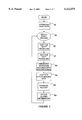
- FIG. 3 is a flowchart illustrating the method
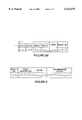
- FIG. 4A represents fault data captured in and downloaded from the electronic control unit
- FIG. 5B is a continuation of FIG. 4A;
- FIG. 6 represents another database table having records that relate to fault description indications and corresponding service recommended action indications
- FIG. 7 illustrates a screen display on the computer system
- ECU 12 includes a display 18 and a button 20 by means of which a technician can review fault codes that ECU 12 captures in a non-volatile memory at the time of an APU failure. Each time the APU is started and thereafter fails, ECU 12 creates a fault record in its non-volatile memory along the lines of those illustrated in FIG. 4A.
- ECU 12 For each fault record, ECU 12 records information identifying the APU (note column labeled "Engine-ID”), information identifying the FADEC, i.e., a configuration number (note column labeled "FADEC No.”), information identifying the record (note column labeled "Start Index”), a fault code (note column labeled "Fault Code”), and a warning code (note column labeled "Warning Code”).
- the fault code is four bytes and the warning code is eight bytes.
- the fault and warning codes represent the status of various APU subsystems, such as a high oil temperature or an air inlet door in the open position.
- ECU 12 If the APU not only failed but also shut itself down, ECU 12 also creates a record in the corresponding portion of its non-volatile memory representing shutdown data, illustrated in FIG. 4B. Note that because the APU may fail and yet not shut down, there will not necessarily be a shutdown record corresponding to each and every fault record.
- ECU 12 records, in addition to the "Engine-ID” and "Start Index", a quantity relating to a measurement of the APU exhaust gas temperature at the time the APU was started (note column labeled "EGT”), a quantity representing the percentage of full operating speed the APU at the time the APU was started (note column labeled "%speed"), a quantity relating to a measurement of the ambient air pressure at the time the APU was started (note column labeled "P AMB "), a quantity relating to a measurement of the ambient air temperature at the time the APU was started (note column labeled "T AMB "), a quantity relating to a measurement of the APU exhaust gas temperature at the time the APU shut down (note second column labeled "EGT”), a quantity representing the percentage of full operating speed the APU at the time the APU shut down (note second column labeled "%speed”), a quantity relating to a measurement of the ambient air pressure
- ECU 12 derives mnemonic symbols generally representative of the type of failure and displays the symbols on display 18.
- the symbol "ACFT: Fire/Door/Battery” is a typical display, indicating to the technician that the fault was an aircraft-type fault and may have involved either a fire, an air inlet or exhaust door, or the battery.
- pressing button 20 FIG. 1
- the technician can scroll through similar information on display 18 relating to other fault records corresponding to earlier instances of APU failure. It should be evident that the displayed information does not diagnose the cause of the failure with any degree of precision.
- the technician typically consults the aircraft manufacturer's maintenance manual, using the displayed information as a starting point to begin diagnosing the problem and determining how to correct it.
- the present invention is intended to address this problem by not only significantly improving diagnostic precision but also providing a recommended action to correct the problem.
- Computer 10 is preferably a laptop, palmtop or similar highly portable computer having a MICROSOFT WINDOWS or similar operating system. As illustrated in FIG. 2, computer 10 includes a main memory 22, a central processing unit 24, a modem 26, a display 28, serial and parallel input/output ports 30, a keyboard 32, a mouse 34 or similar pointing device, a removable-disk drive 36 such as a CD-ROM, DVD, floppy disk or other drive based upon magnetic, optical or similar removable data storage medium 38. Computer 10 further includes a hard disk drive 40. A database 42, described in further detail below, is stored on hard disk drive 40 during operation of the present invention.
- Database 42 and the other operating software of the present invention may be imported into computer 10 by reading it from data storage medium 38 or by downloading it from a remote server (not shown) using modem 26.
- the software includes a fault data downloader 44, a database comparer 46, a fault data searcher 48 and a diagnosis and service recommendation indicator 50.
- these software elements are illustrated in FIG. 2 as existing simultaneously in memory 22 for purposes of explanatory clarity, they may in actuality be retrieved into memory 22 from hard disk 40 or other source in such segments and at such times as the operating system may cause to occur in accordance with well-known operating system principles.
- FIG. 3 illustrates the operation of computer 10 as programmed in accordance with the software.
- Persons skilled in the art will readily be capable of devising suitable software code to effect the methods represented by the flowchart of FIG. 3 in view of the description in this patent specification. Although one may write such software code in any number of suitable computer programming languages, some exemplary software was written in the VISUAL BASIC language.
- Computer 10 may first display some initialization screens (not shown), in which the technician is instructed to enter identifying information for the APU, the airline and the aircraft tail number in which the APU is installed.
- the technician enters data and navigates through the screens using standard windowing user interface conventions, such as activating mouse 34 to select a button or other graphical windowing structure. For example, the user may select or "click on" a Diagnose button 52 to process the most recent fault record.
- computer 10 downloads the most recent data from the APU and displays information pertinent to the first or more recent fault record ("Record #1").
- Computer 10 displays a screen such as illustrated in FIG. 7.
- a scroll bar 54 allows the technician to initiate processing of previous fault records.
- step 56 computer 10 downloads from the non-volatile memory of ECU 12 the fault data described above with regard to FIGS. 4A and 4B.
- the technician selects a fault record. (As noted above, the first fault record is processed first by default, but the technician can scroll through other fault records.)
- computer 10 tests for aircraft-type (“ACFT") anomalies. This step reflects the critical realization that determining the cause of an "ACFT" fault indication may require analysis of the historical fault data, i.e., the fault records corresponding to previous instances of APU failure.
- Computer 10 first determines whether there is a shutdown record (see, e.g., FIG.
- step 60 comparing bits of the fault code of the fault record to bits of the fault code of the shutdown records to determine which, if any, of the shutdown records corresponds to, i.e., was created in response to the same instance of APU failure as, the selected fault record.
- step 62 computer 10 tests for high oil temperature ("HOT") anomalies.
- HOT high oil temperature
- This step reflects a similar critical realization that determining the cause of an "HOT” fault indication may require analysis of the historical fault data. If the "HOT" fault code bit is set, then it is the next oldest shutdown record that corresponds to the selected fault record if the next oldest shutdown record has a different Start Index than the fault record. If the "HOT" fault code bit is set, and the Start Index of the next oldest shutdown record is the same as that of the selected fault record, and the "HOT" fault code bit of the next oldest shutdown record is not set, then the original or previous shutdown record corresponds to the selected fault record.
- step 64 computer 10 associates the remaining shutdown records with the other (non-selected) fault records.
- a shutdown record can be deemed to correspond to a fault record if their Engine-ID and Start Index match.
- step 66 computer 10 tests the fault record data and shutdown record data for values that are out of reasonable bounds. If values are out of reasonable bounds, then it can be inferred that the measurement was incorrect. Computer 10 does not attempt to diagnose a failure if the recorded data is not trustworthy and provides a suitable indication. If all data are within reasonable bounds, computer 10 proceeds to step 68.
- step 68 computer 10 diagnoses the selected record by comparing the fault record data and corresponding shutdown record data to the data stored in database 42, represented by FIGS. 5A-5B.
- the rows may be considered to be records, and the data in each column may be associated or included within any of the records.
- the columns include a first fault indication ("Fault1”) and a second fault indication (“Fault2"). More than one fault code may be associated with an instance of APU failure. The inclusion of these columns reflects the critical realization that certain faults that occur together are indicative of a problem that may not be the same as the problem of which only one of the codes occurring by itself or in combination with still another code would be indicative.
- the data in these columns are the mnemonic symbols that corresponds to the fault code, such as "ACFT.” As noted above, a number of possible faults may be grouped under a single mnemonic symbol, and can only be differentiated from one another by a more complete analysis of the fault code bits.
- the binary fault code itself is included in a "Fault Code” column. These data are compared to that of the downloaded fault code data of the selected fault record.
- the columns also include "Shutdown Fault1" "Shutdown Fault2,” and “Shutdown Code” columns.
- the data in the these columns are the mnemonic symbols and corresponding binary fault codes for shutdown conditions and are compared to the downloaded data of the corresponding shutdown record.
- a "Warning” column and “Warning Code” column store the mnemonic symbol and corresponding binary warning code and are compared to the downloaded warning code data of the selected fault record.
- Another column is the "Build” column, which represents the version or build of the FADEC that identifies it.
- the engineering designs of FADECs occasionally are changed resulting in different versions of a particular FADEC.
- FADECs implemented for a particular APU may be designed by different manufacturers. These different designs and versions may affect the diagnosis, and consequently, the comparison of the data in this column to the identifying information read by the computer 10 may effect the diagnostic process.
- the diagnosis depends upon analysis of the portion of the downloaded fault codes that represent APU engine operating parameters. If the record reflects an analysis of engine parameters, an "Engine Parameters" column is marked. The next group of 18 columns are the values of the engine parameters. Half of these columns store parameters relating to the time of APU shutdown, and the other half store parameters representing the delta or difference between the values of those parameters at APU startup and at APU shutdown. For each parameter, a column is included for a lower limit and a column is included for an upper limit.
- the columns for both shutdown values and delta values are: ambient pressure, lower limit ("P AMB -LL”); ambient pressure, upper limit (“P AMB -UL”); ambient temperature, lower limit (“T AMB -LL”); ambient temperature, upper limit (“T AMB -UL”); exhaust gas temperature, lower limit (“EGT-LL”); exhaust gas temperature, upper limit (“EGT-UL”); percentage of normal engine operating speed, lower limit (“SPD-LL”); percentage of normal engine operating speed, upper limit (“SPD-UL”); fuel, lower limit (“FUEL-LL”) and fuel, upper limit (“FUEL-UL”). Downloaded engine parameter data are deemed to match the values in the database table if they are between the upper and lower limits of that parameter.
- the downloaded fault data and shutdown data are compared to the values in these columns to determine whether they match. If all columns of a record match the downloaded data, that record is deemed to represent a problem that is likely the cause (or one of the causes) of the APU failure. Note that it is possible that the columns of more than one record may match the downloaded data.
- the remaining columns include a "Rank” column and a "Result No.” column.
- the Rank of a record is a value representing an estimate of the relative likelihood that the problem or diagnosis represented by that record is the true cause of the APU failure in comparison with other records that may have the same or similar values. Because the comparison may result in two or more matching records (diagnoses), the Rank is used to sort the diagnoses for presentation to the technician in order of likelihood, with the most likely diagnosis presented first.
- the Result No. is used as an index into the database table illustrated in FIG. 6. This table includes a "Result No.” column, a "Fault Description” column, a "Notes” column, and a "Recommended Action” column. This table is separate from that of FIG. 5 for purposes of convenience, but in other embodiments the tables may be combined or partitioned in any other suitable manner.
- an English description of the Fault code of the indexed record of the table of FIGS. 5A-B are displayed in the "Faults" box 70 on the computer screen, as illustrated in FIGS. 7 and 8.
- the Notes data, if any, of the indexed record of the table of FIG. 6 are displayed in a "Notes” box 71 (FIG. 8)
- an English description of the Warnings code of the indexed record of the table of FIGS. 5A-B are displayed in the "Warnings” box 72
- first tab 82 may be labeled "ACFT" to indicate that the most likely cause of the APU failure was of the aircraft type
- second tab 80 may be labeled "ECU” to indicate that the next most likely cause of the APU failure was of the ECU type.
- multiple fault codes are grouped together in accordance with the relationships between the faults. For example, a shutdown fault is paired with the non-shutdown fault if it is likely that the non-shutdown fault caused the shutdown fault. If multiple non-shutdown faults may have caused the shutdown fault, the faults are paired in accordance with the most likely cause-effect relationship.
- the computer 10 ranks the various combinations of faults, the information displayed to the technician reflects the ranking by displaying the most likely pair of faults as the failure and the corrective action necessary. Since all the faults have actually occurred, all faults are displayed, as described below in reference to step 58, so that the technician may address each fault.
- the failures or faults may be grouped or ranked in other ways. For example, if the likelihood of several events (failures) resulting in a chain reaction of fault codes is greater than other grouping such as pairing of faults, the highest ranked fault will be in accordance with the grouping of those several fault codes generated by the several events.
- ECU 12 typically stores 12 fault records that correspond to the 12 most recent APU runs.
- the user interface further includes "Survey" buttons 84 that a technician can click on to initiate communication with remote personnel or a computer server via modem 26.
- the downloaded fault data can be transmitted for off-site analysis by the APU manufacturer's personnel through a computer.
- Clicking on a "Print” button 86 initiates printing of the data and results if a printer is attached to computer 10.
- Clicking on a "FAQ” button 88 causes a list of frequently asked questions and their answers to be displayed.
- the display includes "Open File”, “Exit”, and "Close” buttons 90, 92 and 94, respectively, that are used in the manner conventional to WINDOWS-based application programs.
Abstract
A system, method, and computer program product assist a technician in troubleshooting an aircraft auxiliary power unit (APU). A portable computer is couplable of download the fault data captured in a memory of the ECU. The fault data corresponds to one or more instances of APU failure. The computer is further programmed to compare the fault data to predetermined fault patterns stored in a database. Each record of the database has one of the fault patterns, a corresponding fault indication, and a corresponding service recommendation indication. The computer is further programmed so that when a record in which the fault pattern matches the fault data is found, the corresponding fault indication and service recommendation are retrieved from the database and provided to the technician via the computer's display or other suitable output mechanism.
Description
1. Field of the Invention
The present invention relates to aircraft auxiliary power units and diagnostic test equipment for them.
2. Description of the Related Art
An auxiliary power unit (APU) provides electrical and pneumatic power to an aircraft when its main engines are not operational, such as when the aircraft is parked. An APU typically includes a jet turbine engine that drives an electrical generator and other equipment, an electronic control unit (ECU), and cockpit-mounted controls. In APUs manufactured by Hamilton Sundstrand, the ECU is also referred to as a full authority digital electronic control (FADEC).
If an APU fails, an aircraft maintenance technician may be called upon to diagnose and correct the problem. Typically, the ECU measures and captures in a non-volatile memory a limited amount of data relating to various APU operating parameters as they were at the time the APU was started and at the time the APU failed. It may capture such data relating to not one but several recent startups and/or failures, e.g., the 12 most recent failures. From this data, the ECU may provide the technician with some limited diagnostic information. For example, a typical ECU has a one-line alphanumeric display on which it displays a fault code such as "HOT" to indicate a High Oil Temperature condition or "ACCL" to indicate a failure of the APU to accelerate to operating speed upon startup. The ECU may include a simple user interface such as a single button that the technician can press to scroll through the fault codes for recent failures. The ECU may record and indicate more than one fault code relating to a failure. For example, scrolling through the records may indicate both a "HOT" fault code and a "ACCL" fault code associated with the most recent failure.
APU fault codes typically represent only a fraction of the potential faults, and typically do not provide the technician with sufficient information to diagnose the cause of the failure. For example, the fault code "ACFT" may indicate only that the fault relates to the aircraft/APU interface. The intent of the displayed information is only to provide a starting point for diagnosis. Technicians must refer to the APU manufacturer's maintenance manual to determine the significance of the code and the possible causes of the problem. There may, for example, be at least six different reasons why the ECU displays the "ACFT" fault code. The manual may instruct the technician to observe other APU conditions or perform further tests to determine which of these reasons is the applicable one.
Systems have been developed to aid a technician in determining which of the possible reasons for failure is associated with a particular fault code. Such a system may include a laptop computer that the technician can couple to the ECU. The computer downloads from the ECU the fault codes as well as additional diagnostic codes that the ECU stores in association with each failure. These additional codes may indicate the state of various APU subsystems at the time of failure. Nevertheless, the ECU stores these additional codes in binary format only, and does not provide any type of mnemonic translation that would be meaningful to a technician. The primary function of the prior laptop-based systems has been simply to read the internal binary codes, translate them into verbiage, and display them.
Even with the aid of a laptop-based system that displays the internal fault codes in the form of verbiage meaningful to a technician, the task of correctly diagnosing and correcting a problem remains daunting due to a number of complicating factors. One such factor is that, of the internal codes that are displayed, only some of them may actually relate to the cause of the problem, while the others relate to effects of the problem. It is difficult for a technician, even with the aid of a maintenance manual, to determine which of the displayed error codes provide meaningful clues for diagnosing the problem and which do not. Further complicating diagnosis, it may not be evident to the technician which of the different fault codes indicate the more severe problems and, as a result, a technician may spend time needlessly diagnosing less severe problems, which may even be effects rather than the causes of the failure, before more severe problems, which are generally more likely to be the causes of the failure.
The data that the ECU records may include more data than that noted above, including, in certain cases, data relating to engine operating parameters such as speed and temperature. This data has been intended for use only by the APU manufacturer's service personnel and has not been usable by maintenance technicians in the field. The APU manufacturer may on occasion retrieve ECUs from aircraft in the field and, by downloading and analyzing this additional data, assess the manner in which its APUs are being used or investigate engineering design issues.
Prior APU diagnostic systems have not advanced considerably beyond the display of cryptic and imprecise fault codes. It would be desirable to provide a troubleshooting system that not only precisely diagnoses APU faults but also recommends corrective action. These problems and deficiencies are clearly felt in the art and are solved by the present invention in the manner described below.
The present invention relates to a system, method, and computer program product for assisting a technician in troubleshooting an aircraft auxiliary power unit (APU). A portable computer is couplable to an electronic control unit (ECU) of the APU and programmed to download fault data captured in a memory of the ECU. The fault data corresponds to one or more instances of APU failure. The computer is further programmed to compare the fault data to predetermined fault patterns stored in a database. Each record of the database has one of the fault patterns, a corresponding fault indication, and a corresponding service recommendation indication. The computer is further programmed so that when a record in which the fault pattern matches the fault data is found, the corresponding fault indication and service recommendation are retrieved from the database and provided to the technician via the computer's display or other suitable output mechanism.
In some embodiments of the present invention, the computer may be programmed to determine whether more than one of the fault patterns matches the fault data, and rank their corresponding fault indications and service recommendations in order of likelihood so that a technician can focus upon those that are more likely to be the true cause of the failure.
In embodiments of the invention in which the downloaded fault data correspond to multiple instances of APU failure, the computer may be programmed to distinguish between those fault data that are likely attributable to the cause of the APU failure and those that are likely attributable to the effects of APU failure. Only those that are attributable to the cause are used to search the database, and those that are attributable to effects may be ignored. For example, once an APU has failed and shut down, attempts to restart it may result in the recordation of further fault data that appears to reflect further instances of APU failure. In such a case, the fault data associated with the initial failure and shutdown are most useful for diagnostic purposes; the further fault data associated with the attempts to restart the APU are not as useful.
The foregoing, together with other features and advantages of the present invention, will become more apparent when referring to the following specification, claims, and accompanying drawings.
For a more complete understanding of the present invention, reference is now made to the following detailed description of the embodiments illustrated in the accompanying drawings, wherein:
FIG. 1 illustrates a system in which a computer system of the present invention is coupled to an APU electronic control unit;
FIG. 2 is a block diagram of the computer system;
FIG. 3 is a flowchart illustrating the method;
FIG. 4A represents fault data captured in and downloaded from the electronic control unit;
FIG. 4B represents fault data associated with an APU shutdown captured in and downloaded from the electronic control unit;
FIG. 5A represents a database table having records that relate to fault data;
FIG. 5B is a continuation of FIG. 4A;
FIG. 6 represents another database table having records that relate to fault description indications and corresponding service recommended action indications;
FIG. 7 illustrates a screen display on the computer system; and
FIG. 8 illustrates another screen display on the computer system.
As illustrated in FIG. 1, a computer 10 is coupled to the electronic control unit (ECU) 12 of an aircraft auxiliary power unit (APU) via a cable 14. ECU 12 is also known as a full authority digital electronic control or FADEC. A service technician couples computer 10 to ECU 12 in this manner after the APU malfunctions and is shut down so that the technician can diagnose and correct the problem. Specifically, the technician couples cable 14 between the serial port of computer 10 and a multi-pin connector 16 of ECU 12. ECU 12 may be, for example, the FADEC of a SUNDSTRAND APS-2000 APU. The operation of ECU 12 is not described in detail in this patent specification because persons skilled in the art to which the invention relates are familiar with the operation of the FADEC of a SUNDSTRAND APS-2000 APU or others like it. Nevertheless, it should at least be noted that ECU 12 includes a display 18 and a button 20 by means of which a technician can review fault codes that ECU 12 captures in a non-volatile memory at the time of an APU failure. Each time the APU is started and thereafter fails, ECU 12 creates a fault record in its non-volatile memory along the lines of those illustrated in FIG. 4A. For each fault record, ECU 12 records information identifying the APU (note column labeled "Engine-ID"), information identifying the FADEC, i.e., a configuration number (note column labeled "FADEC No."), information identifying the record (note column labeled "Start Index"), a fault code (note column labeled "Fault Code"), and a warning code (note column labeled "Warning Code"). In the SUNDSTRAND APS-2000 FADEC, the fault code is four bytes and the warning code is eight bytes. The fault and warning codes represent the status of various APU subsystems, such as a high oil temperature or an air inlet door in the open position. If the APU not only failed but also shut itself down, ECU 12 also creates a record in the corresponding portion of its non-volatile memory representing shutdown data, illustrated in FIG. 4B. Note that because the APU may fail and yet not shut down, there will not necessarily be a shutdown record corresponding to each and every fault record. Each time the APU shuts down as a result of a failure, ECU 12 records, in addition to the "Engine-ID" and "Start Index", a quantity relating to a measurement of the APU exhaust gas temperature at the time the APU was started (note column labeled "EGT"), a quantity representing the percentage of full operating speed the APU at the time the APU was started (note column labeled "%speed"), a quantity relating to a measurement of the ambient air pressure at the time the APU was started (note column labeled "PAMB "), a quantity relating to a measurement of the ambient air temperature at the time the APU was started (note column labeled "TAMB "), a quantity relating to a measurement of the APU exhaust gas temperature at the time the APU shut down (note second column labeled "EGT"), a quantity representing the percentage of full operating speed the APU at the time the APU shut down (note second column labeled "%speed"), a quantity relating to a measurement of the ambient air pressure at the time the APU shut down (note second column labeled "PAMB "), a quantity relating to a measurement of the ambient air temperature at the time the APU shut down (note second column labeled "TAMB "), and the "Fault Code."
From the fault code in the fault record relating to the most recent failure, ECU 12 derives mnemonic symbols generally representative of the type of failure and displays the symbols on display 18. For example, the symbol "ACFT: Fire/Door/Battery" is a typical display, indicating to the technician that the fault was an aircraft-type fault and may have involved either a fire, an air inlet or exhaust door, or the battery. By pressing button 20 (FIG. 1), the technician can scroll through similar information on display 18 relating to other fault records corresponding to earlier instances of APU failure. It should be evident that the displayed information does not diagnose the cause of the failure with any degree of precision. At that point, the technician typically consults the aircraft manufacturer's maintenance manual, using the displayed information as a starting point to begin diagnosing the problem and determining how to correct it. The present invention is intended to address this problem by not only significantly improving diagnostic precision but also providing a recommended action to correct the problem.
To use the invention, after connecting computer 10 to ECU 12 as described above, the technician turns on computer 10 in the conventional manner. A suitable batch file or similar mechanism (not shown) automatically initiates execution of the software of the present invention. The flowchart of FIG. 3 illustrates the operation of computer 10 as programmed in accordance with the software. Persons skilled in the art will readily be capable of devising suitable software code to effect the methods represented by the flowchart of FIG. 3 in view of the description in this patent specification. Although one may write such software code in any number of suitable computer programming languages, some exemplary software was written in the VISUAL BASIC language.
As illustrated in FIG. 3, at step 56 computer 10 downloads from the non-volatile memory of ECU 12 the fault data described above with regard to FIGS. 4A and 4B. At step 58 the technician selects a fault record. (As noted above, the first fault record is processed first by default, but the technician can scroll through other fault records.) At step 60 computer 10 tests for aircraft-type ("ACFT") anomalies. This step reflects the critical realization that determining the cause of an "ACFT" fault indication may require analysis of the historical fault data, i.e., the fault records corresponding to previous instances of APU failure. Computer 10 first determines whether there is a shutdown record (see, e.g., FIG. 4B) that has a Start Index, Engine-ID and Fault Code that are the same as those of the fault record (see, e.g., FIG. 4A) because there are cases in which diagnosis requires a comparison between the fault code in a fault record and the fault code in the corresponding shutdown records. For example, if the bit representing the "ACFT" fault is not set in the fault record but the bit representing the "ACFT" fault is set in the corresponding shutdown record, then a probable cause of the APU failure is that the air inlet door did not open properly. In this case, it is necessary to determine which of the shutdown records corresponds to the selected fault record. Note that there may be multiple shutdown records that superficially appear to be the same, i.e., same "Engine-ID" and same "Start Index," if for example, a pilot attempted to restart an APU that had shut down and could not be restarted, because ECU 12 only generates a new "Start Index" if the APU is successfully started. Thus, an important part of step 60 is comparing bits of the fault code of the fault record to bits of the fault code of the shutdown records to determine which, if any, of the shutdown records corresponds to, i.e., was created in response to the same instance of APU failure as, the selected fault record.
At step 62 computer 10 tests for high oil temperature ("HOT") anomalies. This step reflects a similar critical realization that determining the cause of an "HOT" fault indication may require analysis of the historical fault data. If the "HOT" fault code bit is set, then it is the next oldest shutdown record that corresponds to the selected fault record if the next oldest shutdown record has a different Start Index than the fault record. If the "HOT" fault code bit is set, and the Start Index of the next oldest shutdown record is the same as that of the selected fault record, and the "HOT" fault code bit of the next oldest shutdown record is not set, then the original or previous shutdown record corresponds to the selected fault record. If the "HOT" fault code bit is set, and the Start Index of the next oldest shutdown record is the same as that of the selected fault record, and the "HOT" fault code bit of the next oldest shutdown record is set, then it can be inferred that the APU did not shut down as a result of the instance of APU failure represented by the selected fault record, and no shutdown record corresponds to the selected fault record.
At step 64 computer 10 associates the remaining shutdown records with the other (non-selected) fault records. In this case, a shutdown record can be deemed to correspond to a fault record if their Engine-ID and Start Index match.
At step 66 computer 10 tests the fault record data and shutdown record data for values that are out of reasonable bounds. If values are out of reasonable bounds, then it can be inferred that the measurement was incorrect. Computer 10 does not attempt to diagnose a failure if the recorded data is not trustworthy and provides a suitable indication. If all data are within reasonable bounds, computer 10 proceeds to step 68.
At step 68 computer 10 diagnoses the selected record by comparing the fault record data and corresponding shutdown record data to the data stored in database 42, represented by FIGS. 5A-5B. As in any database, the rows may be considered to be records, and the data in each column may be associated or included within any of the records.
The columns include a first fault indication ("Fault1") and a second fault indication ("Fault2"). More than one fault code may be associated with an instance of APU failure. The inclusion of these columns reflects the critical realization that certain faults that occur together are indicative of a problem that may not be the same as the problem of which only one of the codes occurring by itself or in combination with still another code would be indicative. The data in these columns are the mnemonic symbols that corresponds to the fault code, such as "ACFT." As noted above, a number of possible faults may be grouped under a single mnemonic symbol, and can only be differentiated from one another by a more complete analysis of the fault code bits. The binary fault code itself is included in a "Fault Code" column. These data are compared to that of the downloaded fault code data of the selected fault record.
The columns also include "Shutdown Fault1" "Shutdown Fault2," and "Shutdown Code" columns. The data in the these columns are the mnemonic symbols and corresponding binary fault codes for shutdown conditions and are compared to the downloaded data of the corresponding shutdown record. A "Warning" column and "Warning Code" column store the mnemonic symbol and corresponding binary warning code and are compared to the downloaded warning code data of the selected fault record.
Another column is the "Build" column, which represents the version or build of the FADEC that identifies it. The engineering designs of FADECs occasionally are changed resulting in different versions of a particular FADEC. In addition, it is foreseeable that FADECs implemented for a particular APU may be designed by different manufacturers. These different designs and versions may affect the diagnosis, and consequently, the comparison of the data in this column to the identifying information read by the computer 10 may effect the diagnostic process.
In certain instances, the diagnosis depends upon analysis of the portion of the downloaded fault codes that represent APU engine operating parameters. If the record reflects an analysis of engine parameters, an "Engine Parameters" column is marked. The next group of 18 columns are the values of the engine parameters. Half of these columns store parameters relating to the time of APU shutdown, and the other half store parameters representing the delta or difference between the values of those parameters at APU startup and at APU shutdown. For each parameter, a column is included for a lower limit and a column is included for an upper limit. The columns for both shutdown values and delta values are: ambient pressure, lower limit ("PAMB -LL"); ambient pressure, upper limit ("PAMB -UL"); ambient temperature, lower limit ("TAMB -LL"); ambient temperature, upper limit ("TAMB -UL"); exhaust gas temperature, lower limit ("EGT-LL"); exhaust gas temperature, upper limit ("EGT-UL"); percentage of normal engine operating speed, lower limit ("SPD-LL"); percentage of normal engine operating speed, upper limit ("SPD-UL"); fuel, lower limit ("FUEL-LL") and fuel, upper limit ("FUEL-UL"). Downloaded engine parameter data are deemed to match the values in the database table if they are between the upper and lower limits of that parameter. As described above, the downloaded fault data and shutdown data are compared to the values in these columns to determine whether they match. If all columns of a record match the downloaded data, that record is deemed to represent a problem that is likely the cause (or one of the causes) of the APU failure. Note that it is possible that the columns of more than one record may match the downloaded data.
The remaining columns include a "Rank" column and a "Result No." column. The Rank of a record is a value representing an estimate of the relative likelihood that the problem or diagnosis represented by that record is the true cause of the APU failure in comparison with other records that may have the same or similar values. Because the comparison may result in two or more matching records (diagnoses), the Rank is used to sort the diagnoses for presentation to the technician in order of likelihood, with the most likely diagnosis presented first. The Result No. is used as an index into the database table illustrated in FIG. 6. This table includes a "Result No." column, a "Fault Description" column, a "Notes" column, and a "Recommended Action" column. This table is separate from that of FIG. 5 for purposes of convenience, but in other embodiments the tables may be combined or partitioned in any other suitable manner.
When the comparison results in a matching record, at step 69 an English description of the Fault code of the indexed record of the table of FIGS. 5A-B are displayed in the "Faults" box 70 on the computer screen, as illustrated in FIGS. 7 and 8. Similarly, the Notes data, if any, of the indexed record of the table of FIG. 6 are displayed in a "Notes" box 71 (FIG. 8), an English description of the Warnings code of the indexed record of the table of FIGS. 5A-B are displayed in the "Warnings" box 72, the Shutdown Fault1 and/or Shutdown Fault2 data of the indexed record of the table of FIGS. 5A-B are displayed in the "Shutdown Faults" box 74, the Fault Description data of the indexed record of the table of FIG. 6 are displayed in the "Fault Description" box 76, and the Recommended Action data of the indexed record of the table of FIG. 6 are displayed in the "Recommended Action" box 78.
If the comparison resulted in more than one matching record, the data of the most likely record, i.e., the one having the highest Rank, are displayed first, and the data of the next most likely record are displayed by means of a similar screen display that the technician can activate by clicking on a second tab 80. To return to the display corresponding to the most likely record, the technician can click on the first tab 82. For example, first tab 82 may be labeled "ACFT" to indicate that the most likely cause of the APU failure was of the aircraft type, and second tab 80 may be labeled "ECU" to indicate that the next most likely cause of the APU failure was of the ECU type. If the Engine Parameters column of the matching record is marked, the downloaded engine parameter data are displayed in an "Engine Parameter" box 84.
In an exemplary embodiment of the invention, multiple fault codes are grouped together in accordance with the relationships between the faults. For example, a shutdown fault is paired with the non-shutdown fault if it is likely that the non-shutdown fault caused the shutdown fault. If multiple non-shutdown faults may have caused the shutdown fault, the faults are paired in accordance with the most likely cause-effect relationship. Although the computer 10 ranks the various combinations of faults, the information displayed to the technician reflects the ranking by displaying the most likely pair of faults as the failure and the corrective action necessary. Since all the faults have actually occurred, all faults are displayed, as described below in reference to step 58, so that the technician may address each fault.
In other embodiments of the invention, the failures or faults may be grouped or ranked in other ways. For example, if the likelihood of several events (failures) resulting in a chain reaction of fault codes is greater than other grouping such as pairing of faults, the highest ranked fault will be in accordance with the grouping of those several fault codes generated by the several events.
If the technician uses scroll bar 54 to select the next downloaded fault record (or any other downloaded fault record), computer 10 returns to step 58 and performs the comparison and tests described above with respect to steps 60-69. As noted above, ECU 12 typically stores 12 fault records that correspond to the 12 most recent APU runs.
The user interface further includes "Survey" buttons 84 that a technician can click on to initiate communication with remote personnel or a computer server via modem 26. For example, the downloaded fault data can be transmitted for off-site analysis by the APU manufacturer's personnel through a computer. Clicking on a "Print" button 86 initiates printing of the data and results if a printer is attached to computer 10. Clicking on a "FAQ" button 88 causes a list of frequently asked questions and their answers to be displayed. The display includes "Open File", "Exit", and "Close" buttons 90, 92 and 94, respectively, that are used in the manner conventional to WINDOWS-based application programs.
A comparison of FIG. 7 with FIG. 8 illustrates that APU failures can result in the same fault indication (in this example, "ACFT: Fire/Door/Battery") but be attributable to very different problems. In the case of the failure to which FIG. 7 relates, the system diagnosed the problem an over-temperature condition in the APU air inlet, and recommended cleaning the contacts of the Inlet Temperature Sensor. In the case of the failure to which FIG. 8 relates, the system diagnoses the problem as the air inlet door being left in the fully open position at power-up of the FADEC, and recommended cycling the APU master power switch off and on, among other actions. Note that in contrast to this relatively precise diagnosis and recommended actions, prior systems provided the technician with only the "ACFT" mnemonic code (as displayed on display 18 of ECU 12) or, at most, with a translation of the fault code into a text string such as "Fire/Door/Battery" and the shutdown code into a text string such as "Reverse Flow." The present invention provides a complete Fault Description and a complete Recommended Action in language that is meaningful to a technician.
In addition, the data obtained by the computer 10 is stored and can be used in a variety of ways by the technician or others to more efficiently diagnose, repair and maintain the APU. Diagnostic experts can access the stored data to statistically monitor the various failures, the suggested actions of the program and the repair action that actually fixed the problems. The accuracy of the diagnostic program can be continually improved using the comments submitted by the technician in the survey coupled to the data obtained during the various runs. Another example of using the data for efficient maintenance of the APU includes periodically performing the diagnostic testing on each aircraft to determine the quantity of each type of repair part that should be ordered.
Obviously, other embodiments and modifications of the present invention will occur readily to those of ordinary skill in the art in view of these teachings. Therefore, this invention is to be limited only by the following claims, which include all such other embodiments and modifications when viewed in conjunction with the above specification and accompanying drawings.
Claims (29)
1. A method of diagnosing a failure of an aircraft auxiliary power unit comprising the steps of:
downloading fault data from a memory of an electronic control unit of the auxiliary power unit to a computer;
comparing the fault data to a plurality of fault patterns accessible to the computer to determine a likelihood of the cause of the failure; and
producing an output in accordance with the likelihood of the cause of the failure.
2. A method in accordance with claim 1 further comprising the steps of:
ranking a plurality of possible combinations of faults of the fault data in accordance with the likelihood of the occurrence of the possible combinations of faults to produce a rank; and
producing the output in accordance with the possible combinations and the rank.
3. A method in accordance with claim 2, wherein the step of ranking comprises the steps of:
pairing the faults to produce a plurality of combination pairs; and
comparing each of the plurality of combination pairs to the fault patterns to determine a likely cause and effect relationship.
4. A method for assisting a technician in troubleshooting an aircraft auxiliary power unit (APU), comprising the steps of:
said technician coupling a portable computer to an electronic control unit (ECU) of the APU;
said computer downloading fault data captured in a memory of said ECU, said fault data corresponding to an instance of APU failure;
said computer comparing said fault data to predetermined fault patterns stored in a database in said computer, said database defined by a plurality of records, each record having one of said fault patterns, a corresponding fault indication, and a corresponding service recommendation indication; and
said computer providing to said technician a fault indication and a service recommendation indication corresponding to one of said fault patterns matching said fault data.
5. The method claimed in claim 4, further comprising the steps of:
said computer searching said fault data to determine historical fault data corresponding to a plurality of sequential instances of APU failures;
said computer evaluating said historical fault data in accordance with a predetermined algorithm to determine fault data caused by said instance of APU failure and fault data that are the effect of said instance of APU failure; and
wherein said step of said computer providing to said technician a fault indication and a service recommendation indication comprises providing a fault indication and a service recommendation indication corresponding to one of said fault patterns matching said fault data determined to be caused by said instance of APU failure.
6. The method claimed in claim 5, wherein said fault patterns include engine operating parameter data.
7. The method claimed in claim 6, wherein said engine operating parameter data is selected from the group consisting of engine speed, exhaust gas temperature, ambient temperature and ambient pressure.
8. The method claimed in claim 4, wherein said fault patterns include engine operating parameter data.
9. The method claimed in claim 8, wherein said engine operating parameter data is selected from the group consisting of engine speed, exhaust gas temperature, ambient temperature and ambient pressure.
10. The method claimed in claim 4, further comprising the steps of:
said computer determining whether more than one of said fault patterns matches said fault data; and
if more than one of said fault patterns matches said fault data, said computer providing to said technician in order of likelihood a plurality of fault indications and service recommendations indications corresponding to said fault patterns matching said data.
11. The method claimed in claim 10, wherein each record in said database has a likelihood estimation rank, and said step of said computer providing to said technician in order of likelihood a plurality of fault indications and service recommendations indications corresponding to said fault patterns matching said data is performed in response to said likelihood estimation rank.
12. A method in accordance with claim 11 further comprising the step of determining the likelihood estimation rank based on grouping of faults.
13. A method in accordance with claim 12 wherein the grouping of faults is based on the likelihood of a fault being caused by a second fault.
14. A system for assisting a technician in troubleshooting an aircraft auxiliary power unit (APU), comprising:
a portable computer couplable to an electronic control unit (ECU) of the APU and programmed to include downloading means, comparing means and indicating means;
said downloading means for downloading fault data captured in a memory of said ECU, said fault data corresponding to an instance of APU failure;
said comparing means for comparing said fault data to predetermined fault patterns stored in a database in said computer, said database defined by a plurality of records, each record having one of said fault patterns, a corresponding fault indication, and a corresponding service recommendation indication; and
said indicating means for providing to said technician a fault indication and a service recommendation indication corresponding to one of said fault patterns matching said fault data.
15. The system claimed in claim 14, wherein said fault patterns include engine operating parameter data.
16. The system claimed in claim 15, wherein said engine operating parameter data is selected from the group consisting of engine speed, exhaust gas temperature, ambient temperature and ambient pressure.
17. The system claimed in claim 14, wherein said computer is programmed to further comprise:
multiple fault means for determining whether more than one of said fault patterns matches said fault data; and
said indicating means provides to said technician in order of likelihood a plurality of fault indications and service recommendations indications corresponding to said fault patterns matching said data if more than one of said fault patterns matches said fault data.
18. The system claimed in claim 17, wherein each record in said database has a likelihood estimation rank, and said indicating means provides said plurality of fault indications and service recommendations indications corresponding to said fault patterns matching said data in response to said likelihood estimation rank.
19. The system claimed in claim 14, wherein said computer is programmed to further comprise:
historical searching means for searching said fault data to determine historical fault data corresponding to a plurality of sequential instances of APU failures;
historical evaluation means for evaluating said historical fault data in accordance with a predetermined algorithm to determine fault data caused by said instance of APU failure and fault data that are the effect of said instance of APU failure; and
wherein said indicating means provides a fault indication and a service recommendation indication corresponding to one of said fault patterns matching said fault data determined to be caused by said instance of APU failure.
20. The system claimed in claim 19, wherein said fault patterns include engine operating parameter data.
21. The system claimed in claim 20, wherein said engine operating parameter data is selected from the group consisting of engine speed, exhaust gas temperature, ambient temperature and ambient pressure.
22. A computer program product for assisting a technician in troubleshooting an aircraft auxiliary power unit (APU), said computer program product comprising:
a computer-readable medium carrying thereon:
downloading means for downloading fault data captured in a memory of said ECU, said fault data corresponding to an instance of APU failure;
comparing means for comparing said fault data to predetermined fault patterns stored in a database in said computer, said database defined by a plurality of records, each record having one of said fault patterns, a corresponding fault indication, and a corresponding service recommendation indication; and
indicating means for providing to said technician a fault indication and a service recommendation indication corresponding to one of said fault patterns matching said fault data.
23. The system claimed in claim 22, wherein said fault patterns include engine operating parameter data.
24. The system claimed in claim 23, wherein said engine operating parameter data is selected from the group consisting of engine speed, exhaust gas temperature, ambient temperature and ambient pressure.
25. The system claimed in claim 22, wherein said computer is programmed to further comprise:
multiple fault means for determining whether more than one of said fault patterns matches said fault data; and
said indicating means provides to said technician in order of likelihood a plurality of fault indications and service recommendations indications corresponding to said fault patterns matching said data if more than one of said fault patterns matches said fault data.
26. The system claimed in claim 25, wherein each record in said database has a likelihood estimation rank, and said indicating means provides said plurality of fault indications and service recommendations indications corresponding to said fault patterns matching said data in response to said likelihood estimation rank.
27. The system claimed in claim 22, wherein said computer is programmed to further comprise:
historical searching means for searching said fault data to determine historical fault data corresponding to a plurality of sequential instances of APU failures;
historical evaluation means for evaluating said historical fault data in accordance with a predetermined algorithm to determine fault data caused by said instance of APU failure and fault data that are the effect of said instance of APU failure; and
wherein said indicating means provides a fault indication and a service recommendation indication corresponding to one of said fault patterns matching said fault data determined to be caused by said instance of APU failure.
28. The system claimed in claim 27, wherein said fault patterns include engine operating parameter data.
29. The system claimed in claim 28, wherein said engine operating parameter data is selected from the group consisting of engine speed, exhaust gas temperature, ambient temperature and ambient pressure.
Priority Applications (1)
| Application Number | Priority Date | Filing Date | Title |
|---|---|---|---|
| US09/345,566 US6122575A (en) | 1999-06-30 | 1999-06-30 | APU troubleshooting system |
Applications Claiming Priority (1)
| Application Number | Priority Date | Filing Date | Title |
|---|---|---|---|
| US09/345,566 US6122575A (en) | 1999-06-30 | 1999-06-30 | APU troubleshooting system |
Publications (1)
| Publication Number | Publication Date |
|---|---|
| US6122575A true US6122575A (en) | 2000-09-19 |
Family
ID=23355538
Family Applications (1)
| Application Number | Title | Priority Date | Filing Date |
|---|---|---|---|
| US09/345,566 Expired - Lifetime US6122575A (en) | 1999-06-30 | 1999-06-30 | APU troubleshooting system |
Country Status (1)
| Country | Link |
|---|---|
| US (1) | US6122575A (en) |
Cited By (91)
| Publication number | Priority date | Publication date | Assignee | Title |
|---|---|---|---|---|
| US6317659B1 (en) * | 1999-12-09 | 2001-11-13 | Honeywell International Inc. | Layered subsystem architecture for a flight management system |
| US20020026537A1 (en) * | 2000-08-23 | 2002-02-28 | Schlabach James Edward | Method for training service personnel to service selected equipment |
| US20020049053A1 (en) * | 2000-10-19 | 2002-04-25 | Nec Corporation | Concentrated maintenance management method and concentrated maintenance management system for portable telephone system utilizing the internet |
| US6397128B1 (en) * | 1998-12-30 | 2002-05-28 | Honeywell International Inc. | Flight data recorder system |
| US6401013B1 (en) * | 2000-07-11 | 2002-06-04 | Rockwell Collins, Inc. | Method and system for integrating a laptop PC in a cockpit |
| US20020095597A1 (en) * | 2001-01-13 | 2002-07-18 | Norden Gregory L. | Reusable solutions for aircraft servicing |
| US20020095476A1 (en) * | 2001-01-15 | 2002-07-18 | Ron Craik | System and method for storing and retrieving equipment inspection and maintenance data |
| US20020156692A1 (en) * | 2001-04-20 | 2002-10-24 | Squeglia Mark R. | Method and system for managing supply of replacement parts of a piece of equipment |
| US20030005349A1 (en) * | 2001-06-29 | 2003-01-02 | Ibm Corporation | Architecture for the graphical management and analysis of authentication tokens |
| US20030033062A1 (en) * | 2001-08-10 | 2003-02-13 | Honda Giken Kogyo Kabushiki Kaisha | Data recording system |
| US20030083794A1 (en) * | 2001-10-27 | 2003-05-01 | Juergen Halm | System and method for diagnosing aircraft components for maintenance purposes |
| US6574537B2 (en) | 2001-02-05 | 2003-06-03 | The Boeing Company | Diagnostic system and method |
| US20030191563A1 (en) * | 2002-04-03 | 2003-10-09 | Eagleton Stephen P. | Method and apparatus using historical data to associate deferral procedures and fault models |
| US20030204777A1 (en) * | 2002-04-30 | 2003-10-30 | Kojori Hassan A. | Control sequencing and prognostics health monitoring for digital power conversion and load management |
| US20030218887A1 (en) * | 2002-04-30 | 2003-11-27 | Kojori Hassan A. | Synchronous and bi-directional variable frequency power conversion systems |
| US20040003318A1 (en) * | 2002-06-26 | 2004-01-01 | Felke Timothy J. | Method and apparatus for developing fault codes for complex systems based on historical data |
| US6691064B2 (en) | 2000-12-29 | 2004-02-10 | General Electric Company | Method and system for identifying repeatedly malfunctioning equipment |
| US6697718B2 (en) * | 2001-02-26 | 2004-02-24 | Airbus France | Device for monitoring a plurality of systems of an aircraft, in particular of a transport aircraft |
| WO2004016506A1 (en) * | 2002-08-16 | 2004-02-26 | Honeywell International Inc. | Method and apparatus for improving fault isolation |
| US20040260678A1 (en) * | 2003-06-18 | 2004-12-23 | Microsoft Corporation | State based configuration failure detection using checkpoint comparison |
| US20050066241A1 (en) * | 2003-09-24 | 2005-03-24 | Siemens Aktiengesellschaft | Method, system and device for predictive error recognition in a plant |
| US20050075769A1 (en) * | 2003-10-01 | 2005-04-07 | Eschborn David M. | Aircraft accessory monitor |
| US20050159923A1 (en) * | 2004-01-16 | 2005-07-21 | David Huang | Vehicle diagnostic tool |
| US20050183007A1 (en) * | 2004-02-12 | 2005-08-18 | Lockheed Martin Corporation | Graphical authoring and editing of mark-up language sequences |
| US20050223288A1 (en) * | 2004-02-12 | 2005-10-06 | Lockheed Martin Corporation | Diagnostic fault detection and isolation |
| US20050223290A1 (en) * | 2004-02-12 | 2005-10-06 | Berbaum Richard D | Enhanced diagnostic fault detection and isolation |
| US20050235340A1 (en) * | 2004-04-16 | 2005-10-20 | To William C | Configuration management apparatus and related methods |
| EP1588311A2 (en) * | 2002-12-04 | 2005-10-26 | The Boeing Company | Diagnostic system and method for enabling multistage decision optimization for aircraft preflight dispatch |
| US20050240555A1 (en) * | 2004-02-12 | 2005-10-27 | Lockheed Martin Corporation | Interactive electronic technical manual system integrated with the system under test |
| US20060047394A1 (en) * | 2004-08-27 | 2006-03-02 | Caterpillar Inc. | System for customizing responsiveness of a work machine |
| US20060085692A1 (en) * | 2004-10-06 | 2006-04-20 | Lockheed Martin Corp. | Bus fault detection and isolation |
| US7047112B2 (en) * | 2001-11-13 | 2006-05-16 | Kid-Systeme Gmbh | Control device for a cabin system in an airplane |
| US20060120181A1 (en) * | 2004-10-05 | 2006-06-08 | Lockheed Martin Corp. | Fault detection and isolation with analysis of built-in-test results |
| US20060126608A1 (en) * | 2004-11-05 | 2006-06-15 | Honeywell International Inc. | Method and apparatus for system monitoring and maintenance |
| US20060131380A1 (en) * | 2004-12-17 | 2006-06-22 | Ncr Corporation | Method of determining the cause of an error state in an apparatus |
| US20070179663A1 (en) * | 2006-01-27 | 2007-08-02 | Mcintyre Michael G | Method and apparatus for manufacturing data indexing |
| US7266515B2 (en) | 2000-04-20 | 2007-09-04 | General Electric Company | Method and system for graphically identifying replacement parts for generally complex equipment |
| US20070260374A1 (en) * | 2006-03-31 | 2007-11-08 | Morrison Brian D | Aircraft-engine trend monitoring system |
| US20070294000A1 (en) * | 2006-06-14 | 2007-12-20 | Underdal Olav M | Diagnostic test sequence optimization method and apparatus |
| US20080052281A1 (en) * | 2006-08-23 | 2008-02-28 | Lockheed Martin Corporation | Database insertion and retrieval system and method |
| US20080091310A1 (en) * | 2006-10-17 | 2008-04-17 | Fussell Ronald M | System and method for responding to ground and flight system malfunctions |
| US20080114507A1 (en) * | 2006-11-10 | 2008-05-15 | Ruth Robert S | System and method for situational control of mobile platform maintenance and operation |
| US20080161994A1 (en) * | 2006-12-28 | 2008-07-03 | Detroit Diesel Corporation | Method and system for autogenerating static fault code data based on a unified summary table for heavy duty diesel engines |
| US20080307269A1 (en) * | 2007-06-05 | 2008-12-11 | Compuware Corporation | Resolution of Computer Operations Problems Using Fault Trend Analysis |
| US20080308635A1 (en) * | 2005-07-08 | 2008-12-18 | Poulin Jeffrey S | Automated postal voting system and method |
| US20090018957A1 (en) * | 2001-09-21 | 2009-01-15 | Adams Douglas B | Tool, network and method for asset data updating |
| US20090051502A1 (en) * | 2001-11-13 | 2009-02-26 | Ron Craik | System and method for storing and retrieving equipment inspection and maintenance data |
| US20090152406A1 (en) * | 2007-12-12 | 2009-06-18 | Francisco Jay M | Rotating auxiliary power unit air inlet door |
| US20090192659A1 (en) * | 2008-01-30 | 2009-07-30 | Beebe Clifford A | Aircraft maintenance laptop |
| US20090240468A1 (en) * | 2008-03-20 | 2009-09-24 | Yi Tony Torng | Risk-based design and maintenance systems and methods |
| US20100152924A1 (en) * | 2008-12-12 | 2010-06-17 | Honeywell International Inc. | Next generation electronic flight bag |
| US20100259756A1 (en) * | 2009-04-09 | 2010-10-14 | Brian Powell | Sensor head for a dry powder agent |
| US20100257915A1 (en) * | 2009-04-09 | 2010-10-14 | Scott Ayers | Measurement system for powder based agents |
| US20100259757A1 (en) * | 2009-04-09 | 2010-10-14 | Scott Ayers | Sensor head for a dry powder agent |
| US20100313669A1 (en) * | 2009-06-16 | 2010-12-16 | Ron Harvey Rosenfield | Method of determining overspeed reliability |
| US20110018579A1 (en) * | 2009-07-27 | 2011-01-27 | International Truck Intellectual Property Company, Llc | Auxiliary power unit diagnostic tool |
| ITRM20090624A1 (en) * | 2009-11-27 | 2011-05-28 | Paolo Rinelli | OPERATIONAL PROTOCOL OF MANAGEMENT OF MAINTENANCE ACTIVITIES AND REVIEW OF COMPLEX PARTS AND RELATED COMPONENTS. |
| US20110173988A1 (en) * | 2008-11-13 | 2011-07-21 | Sweet David H | Adaptive fail-fixed system for fadec controlled gas turbine engines |
| US20110257839A1 (en) * | 2005-10-07 | 2011-10-20 | Honeywell International Inc. | Aviation field service report natural language processing |
| US8239094B2 (en) | 2008-04-23 | 2012-08-07 | Spx Corporation | Test requirement list for diagnostic tests |
| US8412402B2 (en) | 2006-06-14 | 2013-04-02 | Spx Corporation | Vehicle state tracking method and apparatus for diagnostic testing |
| US8423226B2 (en) | 2006-06-14 | 2013-04-16 | Service Solutions U.S. Llc | Dynamic decision sequencing method and apparatus for optimizing a diagnostic test plan |
| US8428813B2 (en) | 2006-06-14 | 2013-04-23 | Service Solutions Us Llc | Dynamic decision sequencing method and apparatus for optimizing a diagnostic test plan |
| US8436749B2 (en) | 2010-11-03 | 2013-05-07 | Hamilton Sundstrand Corporation | Failsafe LED control system |
| US8564417B2 (en) | 2001-01-15 | 2013-10-22 | Ron Craik | System and method for storing and retrieving equipment inspection and maintenance data |
| US8648700B2 (en) | 2009-06-23 | 2014-02-11 | Bosch Automotive Service Solutions Llc | Alerts issued upon component detection failure |
| US8762165B2 (en) | 2006-06-14 | 2014-06-24 | Bosch Automotive Service Solutions Llc | Optimizing test procedures for a subject under test |
| US8788138B1 (en) * | 2013-02-26 | 2014-07-22 | Honeywell International Inc. | Diagnostic methods and systems for an aircraft |
| US8864067B2 (en) | 2012-05-31 | 2014-10-21 | Hamilton Sundstrand Corporation | Auxiliary fire resistant mount system for an auxiliary power unit |
| US20140340111A1 (en) * | 2013-05-14 | 2014-11-20 | Airbus Operations (S.A.S.) | System and method of making an integrity test on an electricity network in an aircraft |
| US8903823B1 (en) * | 2011-05-25 | 2014-12-02 | Cadence Design Systems, Inc. | Coverage-based bug clustering |
| US8909981B2 (en) | 2011-06-21 | 2014-12-09 | Hamilton Sundstrand Corporation | Control system software execution during fault detection |
| KR20150012217A (en) * | 2013-07-24 | 2015-02-03 | 에어 차이나 리미티드 | Method and device for monitoring the malfunction of apu turbine vane fracture and rotor shaft jam |
| US20150051756A1 (en) * | 2013-08-14 | 2015-02-19 | The Boeing Company | Aircraft System Control and Reporting via a Mobile Device |
| CN104443425A (en) * | 2013-09-20 | 2015-03-25 | 空中客车运营简化股份公司 | Method for identifying a piece of defective equipment in an aircraft |
| US20150096359A1 (en) * | 2013-10-07 | 2015-04-09 | Ge Aviation Systems Limited | Method for predicting an auxiliary power unit fault |
| CN104540739A (en) * | 2012-08-07 | 2015-04-22 | 庞巴迪公司 | Checklist display system, method and graphical display therefor |
| US20150134187A1 (en) * | 2012-06-28 | 2015-05-14 | Alaska Airlines, Inc. | Robust systems and methods for improving passenger jet aircraft fuel economy |
| US9081883B2 (en) | 2006-06-14 | 2015-07-14 | Bosch Automotive Service Solutions Inc. | Dynamic decision sequencing method and apparatus for optimizing a diagnostic test plan |
| US9207172B2 (en) | 2011-05-26 | 2015-12-08 | Kidde Technologies, Inc. | Velocity survey with powderizer and agent flow indicator |
| US9239991B2 (en) | 2013-09-05 | 2016-01-19 | General Electric Company | Services support system and method |
| US9563989B2 (en) * | 2015-04-17 | 2017-02-07 | Snecma | System and method for maintaining an aircraft engine |
| US9767413B2 (en) | 2013-07-31 | 2017-09-19 | Airbus Operations (S.A.S.) | Method and computer program for the maintenance aid of aircraft equipment |
| US9845734B2 (en) | 2011-04-20 | 2017-12-19 | Honeywell International Inc. | Air turbine start system with monopole starter air valve position |
| US10628246B1 (en) * | 2013-05-20 | 2020-04-21 | The Boeing Company | Methods and systems for prioritizing corrective actions in a troubleshooting chart |
| US10706645B1 (en) * | 2016-03-09 | 2020-07-07 | Drew Technologies, Inc. | Remote diagnostic system and method |
| CN112478183A (en) * | 2020-11-13 | 2021-03-12 | 中国航空工业集团公司西安航空计算技术研究所 | Auxiliary power system protective parking control method for slow task degradation |
| US11097853B2 (en) | 2019-03-18 | 2021-08-24 | Honeywell International Inc. | Edge computing based airplane auxiliary power unit health monitoring system |
| US11142345B2 (en) | 2017-06-22 | 2021-10-12 | Textron Innovations Inc. | System and method for performing a test procedure |
| US11377229B2 (en) | 2019-09-13 | 2022-07-05 | Honeywell International Inc. | Internet connected auxiliary power unit airline maintenance system |
| US11780609B2 (en) * | 2019-06-12 | 2023-10-10 | Honeywell International Inc. | Maintenance recommendations using lifecycle clustering |
Citations (13)
| Publication number | Priority date | Publication date | Assignee | Title |
|---|---|---|---|---|
| US4788531A (en) * | 1983-11-17 | 1988-11-29 | The Boeing Company | Automatic fault reporting system |
| US5617039A (en) * | 1994-11-10 | 1997-04-01 | Applied Data Technology | Auxiliary power unit testing device |
| US5631831A (en) * | 1993-02-26 | 1997-05-20 | Spx Corporation | Diagnosis method for vehicle systems |
| US5670939A (en) * | 1994-05-24 | 1997-09-23 | Mercedes-Benz Ag | Method for evaluation of the self-diagnosis of a controller in a motor vehicle |
| US5696676A (en) * | 1993-02-18 | 1997-12-09 | Nippondenso Co., Ltd. | Self-diagnosis apparatus for vehicles |
| US5778381A (en) * | 1992-05-18 | 1998-07-07 | Aircraft Technical Publishers | Computer aided maintenance and repair information system for equipment subject to regulatory compliance |
| US5838261A (en) * | 1995-12-22 | 1998-11-17 | Aerospatiale Societe Nationale Industrielle | Device for monitoring a complex system such as an aircraft |
| US5883586A (en) * | 1996-07-25 | 1999-03-16 | Honeywell Inc. | Embedded mission avionics data link system |
| US5964813A (en) * | 1996-11-07 | 1999-10-12 | Nissan Motor Co., Ltd. | Vehicle diagnostic data storing system |
| US5964811A (en) * | 1992-08-06 | 1999-10-12 | Hitachi, Ltd. | Control method and apparatus for diagnosing vehicles |
| US6003808A (en) * | 1997-07-11 | 1999-12-21 | Pratt & Whitney Canada Inc. | Maintenance and warranty control system for aircraft |
| US6009356A (en) * | 1996-10-11 | 1999-12-28 | Raytheon Ti Systems | Wireless transducer data capture and retrieval system for aircraft |
| US6014668A (en) * | 1996-10-07 | 2000-01-11 | Ricoh Company, Ltd. | Document information management system and method of generating a human-computer interactive document sheet allowing relevant information retrieval from a remote site |
-
1999
- 1999-06-30 US US09/345,566 patent/US6122575A/en not_active Expired - Lifetime
Patent Citations (13)
| Publication number | Priority date | Publication date | Assignee | Title |
|---|---|---|---|---|
| US4788531A (en) * | 1983-11-17 | 1988-11-29 | The Boeing Company | Automatic fault reporting system |
| US5778381A (en) * | 1992-05-18 | 1998-07-07 | Aircraft Technical Publishers | Computer aided maintenance and repair information system for equipment subject to regulatory compliance |
| US5964811A (en) * | 1992-08-06 | 1999-10-12 | Hitachi, Ltd. | Control method and apparatus for diagnosing vehicles |
| US5696676A (en) * | 1993-02-18 | 1997-12-09 | Nippondenso Co., Ltd. | Self-diagnosis apparatus for vehicles |
| US5631831A (en) * | 1993-02-26 | 1997-05-20 | Spx Corporation | Diagnosis method for vehicle systems |
| US5670939A (en) * | 1994-05-24 | 1997-09-23 | Mercedes-Benz Ag | Method for evaluation of the self-diagnosis of a controller in a motor vehicle |
| US5617039A (en) * | 1994-11-10 | 1997-04-01 | Applied Data Technology | Auxiliary power unit testing device |
| US5838261A (en) * | 1995-12-22 | 1998-11-17 | Aerospatiale Societe Nationale Industrielle | Device for monitoring a complex system such as an aircraft |
| US5883586A (en) * | 1996-07-25 | 1999-03-16 | Honeywell Inc. | Embedded mission avionics data link system |
| US6014668A (en) * | 1996-10-07 | 2000-01-11 | Ricoh Company, Ltd. | Document information management system and method of generating a human-computer interactive document sheet allowing relevant information retrieval from a remote site |
| US6009356A (en) * | 1996-10-11 | 1999-12-28 | Raytheon Ti Systems | Wireless transducer data capture and retrieval system for aircraft |
| US5964813A (en) * | 1996-11-07 | 1999-10-12 | Nissan Motor Co., Ltd. | Vehicle diagnostic data storing system |
| US6003808A (en) * | 1997-07-11 | 1999-12-21 | Pratt & Whitney Canada Inc. | Maintenance and warranty control system for aircraft |
Non-Patent Citations (4)
| Title |
|---|
| Lavitt, M.O., "Need for Greater Value Drives Innovation", Aviation Week & Space Technology, Apr. 20, 1998, pp. 68-69, vol. 148, No. 16. |
| Lavitt, M.O., Need for Greater Value Drives Innovation , Aviation Week & Space Technology, Apr. 20, 1998, pp. 68 69, vol. 148, No. 16. * |
| Presentation at: APS 2000 Operators Conference, Orlando, Florida, Oct. 1997. * |
| Presentation at: APS 2000 Operators' Conference, Orlando, Florida, Oct. 1997. |
Cited By (163)
| Publication number | Priority date | Publication date | Assignee | Title |
|---|---|---|---|---|
| US6397128B1 (en) * | 1998-12-30 | 2002-05-28 | Honeywell International Inc. | Flight data recorder system |
| US6317659B1 (en) * | 1999-12-09 | 2001-11-13 | Honeywell International Inc. | Layered subsystem architecture for a flight management system |
| US7266515B2 (en) | 2000-04-20 | 2007-09-04 | General Electric Company | Method and system for graphically identifying replacement parts for generally complex equipment |
| US6401013B1 (en) * | 2000-07-11 | 2002-06-04 | Rockwell Collins, Inc. | Method and system for integrating a laptop PC in a cockpit |
| US20020026537A1 (en) * | 2000-08-23 | 2002-02-28 | Schlabach James Edward | Method for training service personnel to service selected equipment |
| US6950829B2 (en) | 2000-08-23 | 2005-09-27 | General Electric Company | Method for database storing, accessing personnel to service selected assemblies of selected equipment |
| US20050144183A1 (en) * | 2000-08-23 | 2005-06-30 | Mcquown Christopher M. | Method for guiding repair or replacement of parts for generally complex equipment |
| US6810406B2 (en) | 2000-08-23 | 2004-10-26 | General Electric Company | Method and system for servicing a selected piece of equipment having unique system configurations and servicing requirements |
| US20020049053A1 (en) * | 2000-10-19 | 2002-04-25 | Nec Corporation | Concentrated maintenance management method and concentrated maintenance management system for portable telephone system utilizing the internet |
| US6691064B2 (en) | 2000-12-29 | 2004-02-10 | General Electric Company | Method and system for identifying repeatedly malfunctioning equipment |
| US20020095597A1 (en) * | 2001-01-13 | 2002-07-18 | Norden Gregory L. | Reusable solutions for aircraft servicing |
| US20080228347A1 (en) * | 2001-01-15 | 2008-09-18 | Ron Craik | System and method for storing and retrieving equipment inspection and maintenance data |
| US7383318B2 (en) * | 2001-01-15 | 2008-06-03 | Ron Craik | System and method for storing and retrieving equipment inspection and maintenance data |
| US20020095476A1 (en) * | 2001-01-15 | 2002-07-18 | Ron Craik | System and method for storing and retrieving equipment inspection and maintenance data |
| US7076532B2 (en) * | 2001-01-15 | 2006-07-11 | Ron Craik | System and method for storing and retrieving equipment inspection and maintenance data |
| US20060195550A1 (en) * | 2001-01-15 | 2006-08-31 | Ron Craik | System and method for storing and retrieving equipment inspection and maintenance data |
| US8564417B2 (en) | 2001-01-15 | 2013-10-22 | Ron Craik | System and method for storing and retrieving equipment inspection and maintenance data |
| US6574537B2 (en) | 2001-02-05 | 2003-06-03 | The Boeing Company | Diagnostic system and method |
| US6868319B2 (en) | 2001-02-05 | 2005-03-15 | The Boeing Company | Diagnostic system and method |
| US20030167111A1 (en) * | 2001-02-05 | 2003-09-04 | The Boeing Company | Diagnostic system and method |
| US6697718B2 (en) * | 2001-02-26 | 2004-02-24 | Airbus France | Device for monitoring a plurality of systems of an aircraft, in particular of a transport aircraft |
| US20040158369A1 (en) * | 2001-02-26 | 2004-08-12 | Christine Le Draoullec | Method for monitoring plurality of systems of aircraft including displaying tasks already performed |
| US6993420B2 (en) * | 2001-02-26 | 2006-01-31 | Airbus France | Method for monitoring a plurality of systems of an aircraft including displaying tasks already performed |
| US6912453B2 (en) * | 2001-02-26 | 2005-06-28 | Airbus France | Device for monitoring a plurality of systems of an aircraft including a display displaying tasks already performed |
| US20050187838A1 (en) * | 2001-04-20 | 2005-08-25 | Squeglia Mark R. | Method and system for managing supply of replacement parts of a piece of equipment |
| US20020156692A1 (en) * | 2001-04-20 | 2002-10-24 | Squeglia Mark R. | Method and system for managing supply of replacement parts of a piece of equipment |
| US20030005349A1 (en) * | 2001-06-29 | 2003-01-02 | Ibm Corporation | Architecture for the graphical management and analysis of authentication tokens |
| US6976076B2 (en) * | 2001-06-29 | 2005-12-13 | International Business Machines Corporation | Architecture for the graphical management and analysis of authentication tokens |
| US20030033062A1 (en) * | 2001-08-10 | 2003-02-13 | Honda Giken Kogyo Kabushiki Kaisha | Data recording system |
| US6836712B2 (en) * | 2001-08-10 | 2004-12-28 | Honda Giken Kogyo Kabushiki Kaisha | Data recording system |
| US11087266B2 (en) | 2001-09-21 | 2021-08-10 | International Business Machines Corporation | Asset data updating |
| US20090018957A1 (en) * | 2001-09-21 | 2009-01-15 | Adams Douglas B | Tool, network and method for asset data updating |
| US9881267B2 (en) | 2001-09-21 | 2018-01-30 | International Business Machines Corporation | Tool, network and method for asset data updating |
| US7493276B2 (en) | 2001-09-21 | 2009-02-17 | International Business Machines Corporation | Tool, for asset data management |
| US20030083794A1 (en) * | 2001-10-27 | 2003-05-01 | Juergen Halm | System and method for diagnosing aircraft components for maintenance purposes |
| US7050894B2 (en) * | 2001-10-27 | 2006-05-23 | Airbus Deutschland Gmbh | System and method for diagnosing aircraft components for maintenance purposes |
| US20090051502A1 (en) * | 2001-11-13 | 2009-02-26 | Ron Craik | System and method for storing and retrieving equipment inspection and maintenance data |
| US7047112B2 (en) * | 2001-11-13 | 2006-05-16 | Kid-Systeme Gmbh | Control device for a cabin system in an airplane |
| US8198986B2 (en) | 2001-11-13 | 2012-06-12 | Ron Craik | System and method for storing and retrieving equipment inspection and maintenance data |
| US6725137B2 (en) * | 2002-04-03 | 2004-04-20 | Honeywell International Inc. | Method and apparatus using historical data to associate deferral procedures and fault models |
| US20030191563A1 (en) * | 2002-04-03 | 2003-10-09 | Eagleton Stephen P. | Method and apparatus using historical data to associate deferral procedures and fault models |
| US7308614B2 (en) * | 2002-04-30 | 2007-12-11 | Honeywell International Inc. | Control sequencing and prognostics health monitoring for digital power conversion and load management |
| US20030204777A1 (en) * | 2002-04-30 | 2003-10-30 | Kojori Hassan A. | Control sequencing and prognostics health monitoring for digital power conversion and load management |
| US20030218887A1 (en) * | 2002-04-30 | 2003-11-27 | Kojori Hassan A. | Synchronous and bi-directional variable frequency power conversion systems |
| US6850426B2 (en) | 2002-04-30 | 2005-02-01 | Honeywell International Inc. | Synchronous and bi-directional variable frequency power conversion systems |
| WO2004003746A3 (en) * | 2002-06-26 | 2004-08-19 | Honeywell Int Inc | Method and apparatus for developing fault codes for complex systems based on historical data |
| US7260505B2 (en) * | 2002-06-26 | 2007-08-21 | Honeywell International, Inc. | Method and apparatus for developing fault codes for complex systems based on historical data |
| US20040003318A1 (en) * | 2002-06-26 | 2004-01-01 | Felke Timothy J. | Method and apparatus for developing fault codes for complex systems based on historical data |
| WO2004003746A2 (en) * | 2002-06-26 | 2004-01-08 | Honeywell International Inc. | Method and apparatus for developing fault codes for complex systems based on historical data |
| WO2004016506A1 (en) * | 2002-08-16 | 2004-02-26 | Honeywell International Inc. | Method and apparatus for improving fault isolation |
| US6748304B2 (en) | 2002-08-16 | 2004-06-08 | Honeywell International Inc. | Method and apparatus for improving fault isolation |
| EP1588311A4 (en) * | 2002-12-04 | 2012-02-15 | Boeing Co | Diagnostic system and method for enabling multistage decision optimization for aircraft preflight dispatch |
| EP1588311A2 (en) * | 2002-12-04 | 2005-10-26 | The Boeing Company | Diagnostic system and method for enabling multistage decision optimization for aircraft preflight dispatch |
| US20040260678A1 (en) * | 2003-06-18 | 2004-12-23 | Microsoft Corporation | State based configuration failure detection using checkpoint comparison |
| US7162312B2 (en) * | 2003-09-24 | 2007-01-09 | Siemens Aktiengesellschaft | Method, system and device for predictive error recognition in a plant |
| US20050066241A1 (en) * | 2003-09-24 | 2005-03-24 | Siemens Aktiengesellschaft | Method, system and device for predictive error recognition in a plant |
| US7251550B2 (en) | 2003-10-01 | 2007-07-31 | Honeywell International Inc. | Aircraft accessory monitor |
| US20050075769A1 (en) * | 2003-10-01 | 2005-04-07 | Eschborn David M. | Aircraft accessory monitor |
| US7085680B2 (en) * | 2004-01-16 | 2006-08-01 | Innova Electronics Corporation | Vehicle diagnostic tool |
| US20050159923A1 (en) * | 2004-01-16 | 2005-07-21 | David Huang | Vehicle diagnostic tool |
| US20050183007A1 (en) * | 2004-02-12 | 2005-08-18 | Lockheed Martin Corporation | Graphical authoring and editing of mark-up language sequences |
| US20050223288A1 (en) * | 2004-02-12 | 2005-10-06 | Lockheed Martin Corporation | Diagnostic fault detection and isolation |
| US20050240555A1 (en) * | 2004-02-12 | 2005-10-27 | Lockheed Martin Corporation | Interactive electronic technical manual system integrated with the system under test |
| US7584420B2 (en) | 2004-02-12 | 2009-09-01 | Lockheed Martin Corporation | Graphical authoring and editing of mark-up language sequences |
| US7801702B2 (en) | 2004-02-12 | 2010-09-21 | Lockheed Martin Corporation | Enhanced diagnostic fault detection and isolation |
| US20050223290A1 (en) * | 2004-02-12 | 2005-10-06 | Berbaum Richard D | Enhanced diagnostic fault detection and isolation |
| US20050235340A1 (en) * | 2004-04-16 | 2005-10-20 | To William C | Configuration management apparatus and related methods |
| US7734740B2 (en) * | 2004-04-16 | 2010-06-08 | The Boeing Company | Configuration management apparatus and related methods |
| US20060047394A1 (en) * | 2004-08-27 | 2006-03-02 | Caterpillar Inc. | System for customizing responsiveness of a work machine |
| US7702443B2 (en) | 2004-08-27 | 2010-04-20 | Caterpillar Inc. | System for customizing responsiveness of a machine |
| US20080255712A1 (en) * | 2004-08-27 | 2008-10-16 | Caterpillar Inc. | System for customizing responsiveness of a machine |
| US7400959B2 (en) | 2004-08-27 | 2008-07-15 | Caterpillar Inc. | System for customizing responsiveness of a work machine |
| US20060120181A1 (en) * | 2004-10-05 | 2006-06-08 | Lockheed Martin Corp. | Fault detection and isolation with analysis of built-in-test results |
| US20060085692A1 (en) * | 2004-10-06 | 2006-04-20 | Lockheed Martin Corp. | Bus fault detection and isolation |
| US20060126608A1 (en) * | 2004-11-05 | 2006-06-15 | Honeywell International Inc. | Method and apparatus for system monitoring and maintenance |
| US7702435B2 (en) | 2004-11-05 | 2010-04-20 | Honeywell International Inc. | Method and apparatus for system monitoring and maintenance |
| US7600671B2 (en) | 2004-12-17 | 2009-10-13 | Ncr Corporation | Method of determining the cause of an error state in an apparatus |
| US20060131380A1 (en) * | 2004-12-17 | 2006-06-22 | Ncr Corporation | Method of determining the cause of an error state in an apparatus |
| US20080120282A1 (en) * | 2004-12-23 | 2008-05-22 | Lockheed Martin Corporation | Interactive electronic technical manual system with database insertion and retrieval |
| US7823062B2 (en) | 2004-12-23 | 2010-10-26 | Lockheed Martin Corporation | Interactive electronic technical manual system with database insertion and retrieval |
| US20080308635A1 (en) * | 2005-07-08 | 2008-12-18 | Poulin Jeffrey S | Automated postal voting system and method |
| US9886478B2 (en) * | 2005-10-07 | 2018-02-06 | Honeywell International Inc. | Aviation field service report natural language processing |
| US20110257839A1 (en) * | 2005-10-07 | 2011-10-20 | Honeywell International Inc. | Aviation field service report natural language processing |
| US7583833B2 (en) * | 2006-01-27 | 2009-09-01 | Advanced Micro Devices, Inc. | Method and apparatus for manufacturing data indexing |
| US20070179663A1 (en) * | 2006-01-27 | 2007-08-02 | Mcintyre Michael G | Method and apparatus for manufacturing data indexing |
| US20070260374A1 (en) * | 2006-03-31 | 2007-11-08 | Morrison Brian D | Aircraft-engine trend monitoring system |
| US7979192B2 (en) * | 2006-03-31 | 2011-07-12 | Morrison Brian D | Aircraft-engine trend monitoring system |
| US8423226B2 (en) | 2006-06-14 | 2013-04-16 | Service Solutions U.S. Llc | Dynamic decision sequencing method and apparatus for optimizing a diagnostic test plan |
| US9081883B2 (en) | 2006-06-14 | 2015-07-14 | Bosch Automotive Service Solutions Inc. | Dynamic decision sequencing method and apparatus for optimizing a diagnostic test plan |
| US8762165B2 (en) | 2006-06-14 | 2014-06-24 | Bosch Automotive Service Solutions Llc | Optimizing test procedures for a subject under test |
| US8428813B2 (en) | 2006-06-14 | 2013-04-23 | Service Solutions Us Llc | Dynamic decision sequencing method and apparatus for optimizing a diagnostic test plan |
| US20070294000A1 (en) * | 2006-06-14 | 2007-12-20 | Underdal Olav M | Diagnostic test sequence optimization method and apparatus |
| US8412402B2 (en) | 2006-06-14 | 2013-04-02 | Spx Corporation | Vehicle state tracking method and apparatus for diagnostic testing |
| US7865278B2 (en) * | 2006-06-14 | 2011-01-04 | Spx Corporation | Diagnostic test sequence optimization method and apparatus |
| US20080052281A1 (en) * | 2006-08-23 | 2008-02-28 | Lockheed Martin Corporation | Database insertion and retrieval system and method |
| US7742854B2 (en) * | 2006-10-17 | 2010-06-22 | Boeing Management Company | System and method for responding to ground and flight system malfunctions |
| US20080091310A1 (en) * | 2006-10-17 | 2008-04-17 | Fussell Ronald M | System and method for responding to ground and flight system malfunctions |
| US20080114507A1 (en) * | 2006-11-10 | 2008-05-15 | Ruth Robert S | System and method for situational control of mobile platform maintenance and operation |
| US20080161994A1 (en) * | 2006-12-28 | 2008-07-03 | Detroit Diesel Corporation | Method and system for autogenerating static fault code data based on a unified summary table for heavy duty diesel engines |
| US7676695B2 (en) * | 2007-06-05 | 2010-03-09 | Compuware Corporation | Resolution of computer operations problems using fault trend analysis |
| US7934126B1 (en) | 2007-06-05 | 2011-04-26 | Compuware Corporation | Resolution of computer operations problems using fault trend analysis |
| US20080307269A1 (en) * | 2007-06-05 | 2008-12-11 | Compuware Corporation | Resolution of Computer Operations Problems Using Fault Trend Analysis |
| US20090152406A1 (en) * | 2007-12-12 | 2009-06-18 | Francisco Jay M | Rotating auxiliary power unit air inlet door |
| US8096498B2 (en) | 2007-12-12 | 2012-01-17 | Hamilton Sundstrand Corporation | Rotating auxiliary power unit air inlet door |
| US20090192659A1 (en) * | 2008-01-30 | 2009-07-30 | Beebe Clifford A | Aircraft maintenance laptop |
| WO2009097554A1 (en) * | 2008-01-30 | 2009-08-06 | The Boeing Company | Aircraft maintenance laptop |
| US8321083B2 (en) | 2008-01-30 | 2012-11-27 | The Boeing Company | Aircraft maintenance laptop |
| US7840376B2 (en) | 2008-03-20 | 2010-11-23 | The Boeing Company | Risk-based design and maintenance systems and methods |
| US20090240468A1 (en) * | 2008-03-20 | 2009-09-24 | Yi Tony Torng | Risk-based design and maintenance systems and methods |
| US8239094B2 (en) | 2008-04-23 | 2012-08-07 | Spx Corporation | Test requirement list for diagnostic tests |
| US20110173988A1 (en) * | 2008-11-13 | 2011-07-21 | Sweet David H | Adaptive fail-fixed system for fadec controlled gas turbine engines |
| US9217376B2 (en) | 2008-11-13 | 2015-12-22 | Sikorsky Aircraft Corporation | Multi-mode adaptive fail-fixed system for FADEC controlled gas turbine engines |
| EP2196775A3 (en) * | 2008-12-12 | 2012-06-27 | Honeywell International Inc. | Next generation electronic flight bag |
| US9719799B2 (en) | 2008-12-12 | 2017-08-01 | Honeywell International Inc. | Next generation electronic flight bag |
| US20100152924A1 (en) * | 2008-12-12 | 2010-06-17 | Honeywell International Inc. | Next generation electronic flight bag |
| US8004684B2 (en) | 2009-04-09 | 2011-08-23 | Kidde Technologies, Inc. | Sensor head for a dry powder agent |
| US8077317B2 (en) | 2009-04-09 | 2011-12-13 | Kidde Technologies, Inc. | Sensor head for a dry powder agent |
| US20100259756A1 (en) * | 2009-04-09 | 2010-10-14 | Brian Powell | Sensor head for a dry powder agent |
| US8161790B2 (en) | 2009-04-09 | 2012-04-24 | Kidde Technologies, Inc. | Measurement system for powder based agents |
| US20100257915A1 (en) * | 2009-04-09 | 2010-10-14 | Scott Ayers | Measurement system for powder based agents |
| US20100259757A1 (en) * | 2009-04-09 | 2010-10-14 | Scott Ayers | Sensor head for a dry powder agent |
| US8042406B2 (en) | 2009-06-16 | 2011-10-25 | Hamilton Sundstrand Corporation | Method of determining overspeed reliability |
| US20100313669A1 (en) * | 2009-06-16 | 2010-12-16 | Ron Harvey Rosenfield | Method of determining overspeed reliability |
| US8648700B2 (en) | 2009-06-23 | 2014-02-11 | Bosch Automotive Service Solutions Llc | Alerts issued upon component detection failure |
| US20110018579A1 (en) * | 2009-07-27 | 2011-01-27 | International Truck Intellectual Property Company, Llc | Auxiliary power unit diagnostic tool |
| US8283942B2 (en) * | 2009-07-27 | 2012-10-09 | International Truck Intellectual Property Company, Llc | Auxiliary power unit diagnostic tool |
| ITRM20090624A1 (en) * | 2009-11-27 | 2011-05-28 | Paolo Rinelli | OPERATIONAL PROTOCOL OF MANAGEMENT OF MAINTENANCE ACTIVITIES AND REVIEW OF COMPLEX PARTS AND RELATED COMPONENTS. |
| US8436749B2 (en) | 2010-11-03 | 2013-05-07 | Hamilton Sundstrand Corporation | Failsafe LED control system |
| US9845734B2 (en) | 2011-04-20 | 2017-12-19 | Honeywell International Inc. | Air turbine start system with monopole starter air valve position |
| US8903823B1 (en) * | 2011-05-25 | 2014-12-02 | Cadence Design Systems, Inc. | Coverage-based bug clustering |
| US9207172B2 (en) | 2011-05-26 | 2015-12-08 | Kidde Technologies, Inc. | Velocity survey with powderizer and agent flow indicator |
| US8909981B2 (en) | 2011-06-21 | 2014-12-09 | Hamilton Sundstrand Corporation | Control system software execution during fault detection |
| US8864067B2 (en) | 2012-05-31 | 2014-10-21 | Hamilton Sundstrand Corporation | Auxiliary fire resistant mount system for an auxiliary power unit |
| US9311759B2 (en) * | 2012-06-28 | 2016-04-12 | Alaska Airlines, Inc. | Robust systems and methods for improving passenger jet aircraft fuel economy |
| US20150134187A1 (en) * | 2012-06-28 | 2015-05-14 | Alaska Airlines, Inc. | Robust systems and methods for improving passenger jet aircraft fuel economy |
| CN104540739A (en) * | 2012-08-07 | 2015-04-22 | 庞巴迪公司 | Checklist display system, method and graphical display therefor |
| US10399695B2 (en) | 2012-08-07 | 2019-09-03 | C Series Aircraft Limited Partnership | Checklist display system, method and graphical display therefor |
| US8788138B1 (en) * | 2013-02-26 | 2014-07-22 | Honeywell International Inc. | Diagnostic methods and systems for an aircraft |
| EP2770391A1 (en) * | 2013-02-26 | 2014-08-27 | Honeywell International Inc. | Diagnostic methods and systems for an aircraft |
| US9696386B2 (en) * | 2013-05-14 | 2017-07-04 | Airbus Operations (S.A.S.) | System and method of making an integrity test on an electricity network in an aircraft |
| US20140340111A1 (en) * | 2013-05-14 | 2014-11-20 | Airbus Operations (S.A.S.) | System and method of making an integrity test on an electricity network in an aircraft |
| US10628246B1 (en) * | 2013-05-20 | 2020-04-21 | The Boeing Company | Methods and systems for prioritizing corrective actions in a troubleshooting chart |
| KR20150012217A (en) * | 2013-07-24 | 2015-02-03 | 에어 차이나 리미티드 | Method and device for monitoring the malfunction of apu turbine vane fracture and rotor shaft jam |
| US9632010B2 (en) * | 2013-07-24 | 2017-04-25 | Air China Limited | Method and device for monitoring the malfunction of APU turbine vane fracture and rotor shaft jam |
| US20150068293A1 (en) * | 2013-07-24 | 2015-03-12 | Air China Limited | Method and device for monitoring the malfunction of apu turbine vane fracture and rotor shaft jam |
| TWI625273B (en) * | 2013-07-24 | 2018-06-01 | Monitoring method and device for aircraft auxiliary power unit (APU) turbine blade fracture and shaft blocking failure | |
| US9767413B2 (en) | 2013-07-31 | 2017-09-19 | Airbus Operations (S.A.S.) | Method and computer program for the maintenance aid of aircraft equipment |
| US20150051756A1 (en) * | 2013-08-14 | 2015-02-19 | The Boeing Company | Aircraft System Control and Reporting via a Mobile Device |
| US9239991B2 (en) | 2013-09-05 | 2016-01-19 | General Electric Company | Services support system and method |
| CN104443425A (en) * | 2013-09-20 | 2015-03-25 | 空中客车运营简化股份公司 | Method for identifying a piece of defective equipment in an aircraft |
| US9834317B2 (en) * | 2013-09-20 | 2017-12-05 | Airbus Operations (S.A.S.) | Method for identifying a piece of defective equipment in an aircraft |
| US20150088363A1 (en) * | 2013-09-20 | 2015-03-26 | Airbus Operations (S.A.S.) | Method for identifying a piece of defective equipment in an aircraft |
| CN104443425B (en) * | 2013-09-20 | 2018-06-22 | 空中客车运营简化股份公司 | For identifying the method for the defective equipment in aircraft |
| US9437054B2 (en) * | 2013-10-07 | 2016-09-06 | Ge Aviation Systems Limited | Method for predicting an auxiliary power unit fault |
| US20150096359A1 (en) * | 2013-10-07 | 2015-04-09 | Ge Aviation Systems Limited | Method for predicting an auxiliary power unit fault |
| US9563989B2 (en) * | 2015-04-17 | 2017-02-07 | Snecma | System and method for maintaining an aircraft engine |
| US10706645B1 (en) * | 2016-03-09 | 2020-07-07 | Drew Technologies, Inc. | Remote diagnostic system and method |
| US11142345B2 (en) | 2017-06-22 | 2021-10-12 | Textron Innovations Inc. | System and method for performing a test procedure |
| US11097853B2 (en) | 2019-03-18 | 2021-08-24 | Honeywell International Inc. | Edge computing based airplane auxiliary power unit health monitoring system |
| US11780609B2 (en) * | 2019-06-12 | 2023-10-10 | Honeywell International Inc. | Maintenance recommendations using lifecycle clustering |
| US11377229B2 (en) | 2019-09-13 | 2022-07-05 | Honeywell International Inc. | Internet connected auxiliary power unit airline maintenance system |
| CN112478183A (en) * | 2020-11-13 | 2021-03-12 | 中国航空工业集团公司西安航空计算技术研究所 | Auxiliary power system protective parking control method for slow task degradation |
| CN112478183B (en) * | 2020-11-13 | 2023-10-13 | 中国航空工业集团公司西安航空计算技术研究所 | Auxiliary power system protective parking control method for slow task degradation |
Similar Documents
| Publication | Publication Date | Title |
|---|---|---|
| US6122575A (en) | APU troubleshooting system | |
| US5010487A (en) | Computer-based engine diagnostic method | |
| US5408412A (en) | Engine fault diagnostic system | |
| US8370045B2 (en) | Starter control valve failure prediction machine to predict and trend starter control valve failures in gas turbine engines using a starter control valve health prognostic, program product and related methods | |
| US6691253B1 (en) | System and method for sequencing and performing very high speed software downloads concurrent with system testing in an automated production environment | |
| KR100422994B1 (en) | Method and apparatus for diagnosing the failure of vehicle and computer accessible recording medium storing failure diagnosing program | |
| US5001714A (en) | Unpredictable fault detection using adaptive inference testing techniques | |
| US6338148B1 (en) | Real-time test controller | |
| US6219626B1 (en) | Automated diagnostic system | |
| US7369932B2 (en) | System and method for turbine engine fault detection using discrete event system modeling | |
| US4766595A (en) | Fault diagnostic system incorporating behavior models | |
| US6473659B1 (en) | System and method for integrating a plurality of diagnostic related information | |
| JP4271282B2 (en) | Diagnostic system | |
| US5758062A (en) | Method and apparatus for regression testing of application logic | |
| US4943919A (en) | Central maintenance computer system and fault data handling method | |
| US6643592B1 (en) | System and method for fault diagnosis | |
| US5164912A (en) | Expert system tester | |
| WO2006071710A1 (en) | Test procedures using pictures | |
| US20020138168A1 (en) | Method and apparatus for monitoring the operation of an industrial process | |
| US7203879B2 (en) | Built-in-test diagnostic and maintenance support system and process | |
| US5020011A (en) | System for displaying adaptive inference testing device information | |
| US6615160B1 (en) | Methods and apparatus for engine diagnostics | |
| US5043987A (en) | Method for calculating adaptive inference test figure of merit | |
| US5068814A (en) | Interactive adaptive inference system | |
| US20040153800A1 (en) | Device and system for maintaining a complex system, particularly an aircraft |
Legal Events
| Date | Code | Title | Description |
|---|---|---|---|
| AS | Assignment |
Owner name: HAMILTON SUNDSTRAND, ILLINOIS Free format text: ASSIGNMENT OF ASSIGNORS INTEREST;ASSIGNORS:SCHMIDT, DENNIS E.;HANUS, MICHAEL D.;REEL/FRAME:010204/0552 Effective date: 19990810 |
|
| STCF | Information on status: patent grant |
Free format text: PATENTED CASE |
|
| FPAY | Fee payment |
Year of fee payment: 4 |
|
| FEPP | Fee payment procedure |
Free format text: PAYOR NUMBER ASSIGNED (ORIGINAL EVENT CODE: ASPN); ENTITY STATUS OF PATENT OWNER: LARGE ENTITY |
|
| FPAY | Fee payment |
Year of fee payment: 8 |
|
| FPAY | Fee payment |
Year of fee payment: 12 |