US6128970A - Force feed back manipulator employing wires and spools - Google Patents
Force feed back manipulator employing wires and spools Download PDFInfo
- Publication number
- US6128970A US6128970A US08/773,869 US77386996A US6128970A US 6128970 A US6128970 A US 6128970A US 77386996 A US77386996 A US 77386996A US 6128970 A US6128970 A US 6128970A
- Authority
- US
- United States
- Prior art keywords
- spool
- moving
- plate
- lower fixed
- moving plate
- Prior art date
- Legal status (The legal status is an assumption and is not a legal conclusion. Google has not performed a legal analysis and makes no representation as to the accuracy of the status listed.)
- Expired - Fee Related
Links
Images


Classifications
-
- G—PHYSICS
- G05—CONTROLLING; REGULATING
- G05G—CONTROL DEVICES OR SYSTEMS INSOFAR AS CHARACTERISED BY MECHANICAL FEATURES ONLY
- G05G9/00—Manually-actuated control mechanisms provided with one single controlling member co-operating with two or more controlled members, e.g. selectively, simultaneously
- G05G9/02—Manually-actuated control mechanisms provided with one single controlling member co-operating with two or more controlled members, e.g. selectively, simultaneously the controlling member being movable in different independent ways, movement in each individual way actuating one controlled member only
- G05G9/04—Manually-actuated control mechanisms provided with one single controlling member co-operating with two or more controlled members, e.g. selectively, simultaneously the controlling member being movable in different independent ways, movement in each individual way actuating one controlled member only in which movement in two or more ways can occur simultaneously
- G05G9/047—Manually-actuated control mechanisms provided with one single controlling member co-operating with two or more controlled members, e.g. selectively, simultaneously the controlling member being movable in different independent ways, movement in each individual way actuating one controlled member only in which movement in two or more ways can occur simultaneously the controlling member being movable by hand about orthogonal axes, e.g. joysticks
- G05G9/04737—Manually-actuated control mechanisms provided with one single controlling member co-operating with two or more controlled members, e.g. selectively, simultaneously the controlling member being movable in different independent ways, movement in each individual way actuating one controlled member only in which movement in two or more ways can occur simultaneously the controlling member being movable by hand about orthogonal axes, e.g. joysticks with six degrees of freedom
-
- Y—GENERAL TAGGING OF NEW TECHNOLOGICAL DEVELOPMENTS; GENERAL TAGGING OF CROSS-SECTIONAL TECHNOLOGIES SPANNING OVER SEVERAL SECTIONS OF THE IPC; TECHNICAL SUBJECTS COVERED BY FORMER USPC CROSS-REFERENCE ART COLLECTIONS [XRACs] AND DIGESTS
- Y10—TECHNICAL SUBJECTS COVERED BY FORMER USPC
- Y10T—TECHNICAL SUBJECTS COVERED BY FORMER US CLASSIFICATION
- Y10T74/00—Machine element or mechanism
- Y10T74/20—Control lever and linkage systems
- Y10T74/20012—Multiple controlled elements
- Y10T74/20201—Control moves in two planes
Definitions
- the present invention is directed to a force feed back manipulator having six degrees of freedom; and, more particularly, to a force feed back manipulator having a reduced size and being capable of determining parameters required to control a position and an orientation of an object in a three dimensional space by employing wires and spools.
- FIG. 1 there is shown a prior art parallel manipulator 10 employing hydraulic cylinders.
- the manipulator 10 has a triangular fixed plate 18 and a triangular moving plate 12 positioned above the fixed plate 18 with a separation therebetween.
- Six hydraulic cylinders 16a, 16b, 16c, 16d, 16e and 16f connect the moving plate 12 to the fixed plate 18.
- the moving plate 12 is able to move with six degrees of freedom with respect to the fixed plate 18, wherein the six degrees of freedom referes three translational movements along X, Y and Z axis in rectangular coordinates and three rotational movements about the three axis.
- the six hydraulic cylinders 16a, 16b, 16c, 16d, 16e and 16f experience variations in their length, respectively.
- the six length variations of the hydraulic cylinders 16a, 16b, 16c, 16d, 16e and 16f which indicate how the moving plate 12 was moved with respect to the fixed plate 18 are measured by a detection device (not shown).
- the measured values are data which a simulator or movement reproducing system requires in understanding and reproducing the position or the orientation changes of the moving plate 12.
- the manipulator structured in this manner is too large in size to be used with a small sized simulator or the like because it employs hydraulic cylinders.
- FIG. 2 Another prior art manipulator 20 for overcoming the shortcoming in the hydraulic cylinder type manipulator 10 is shown in FIG. 2.
- the manipulator 20 includes a moving plate 24 having a control stick 22 and a fixed plate 28.
- the moving plate 24 is connected to the fixed plate 28 through three link assemblies 34a, 34b and 34c which connect three frames 28a, 28b and 28c on the fixed plate 28 to three universal joints (only 32a and 32b are shown).
- One link assembly 34a includes four links and is hinged to the universal joint 32a and the frame 28a. Mounted on the frame 28a are a sun gear 30a rotatable about a crossing of the links, and two planetary gears 38a and 38b engaged with the sun gear 30a.
- the planetary gears 38a and 38b are connected to shafts of DC motors 40, respectively.
- Each of the DC motors 40 has a shaft encoder 42 which detects a rotation of the planetary gear.
- the links move in response to the movement of the moving plate 24, rotating the planetary gears 38a and 38b around the sun gear 30a.
- the rotation of the planetary gears 38a and 38b are detected by the shaft encoders 42 and sent to an electronic control unit (not shown).
- a manipulator of six degrees of freedom comprising: a moving plate having six moving points arranged with substantial equal angles therebetween; an upper fixed plate having six upper fixed points arranged with substantial equal angles therebetween, the upper fixed plate being positioned above the moving plate and being spaced apart from the moving plate; a lower fixed plate having six lower fixed points arranged with substantial equal angles therebetween, the lower fixed plate being positioned under the moving plate and being spaced apart from the moving plate; and six connection and detection means each of which connects one of the six moving points to one of the six upper fixed points and to one of the six lower fixed points, respectively, thereby enabling the moving plate to move relative to the upper and the lower fixed plates with six degrees of freedom and each of which detects distance variations between said one moving point and said one upper fixed point, and between said one moving point and said one lower fixed point, when the moving plate moves.
- FIG. 1 shows a schematic view of a prior art parallel manipulator employing hydraulic cylinders
- FIG. 2 represents a perspective view of a prior art parallel manipulator employing links
- FIG. 3 illustrates a perspective view of a force feed back manipulator having six degrees of freedom in accordance with the present invention
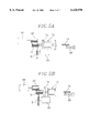
- FIG. 4 depicts a sectional view of the inventive manipulator, when taken along a line A-A' in FIG. 3;
- FIGS. 5A and 5B present schematic views showing longitudinal back and forth movements of a spool of the inventive manipulator
- FIG. 6 offers a perspective view of a second embodiment of the inventive manipulator.
- FIG. 7 is a block diagram showing a force feed back conception of the inventive manipulator.
- FIG. 3 shows a perspective view of a first embodiment of an inventive force feed back manipulator 50.
- the inventive manipulator 50 has four plate-shaped components 64, 56, 68 and 58 vertically spaced apart from each other.
- a moving plate 56 is positioned between an upper fixed plate 64 of a donut shape and a lower fixed plate 58, the moving plate 56 being spaced apart from both fixed plates 64 and 58.
- the moving plate 56 has six anchor portions 54 on its circumferential surface, which are angularly equally arranged with respect to each other.
- a first and a second wires 78' and 78 are fixed to an upper and a lower portions of each of the anchor portions 54.
- the moving plate 56 further has a handling stick 52 vertically extending from an upper surface thereof to pass through a through-hole 60 of the upper fixed plate 64.
- the upper fixed plate 64 has six wire rollers 62 which six first wires 78' pass through, the six first wires 78 being wound therearound.
- the six wire rollers 62 are angularly equally arranged on the upper fixed plate 64.
- the upper fixed plate 64 is fixed to a housing (not shown) of the manipulator 50.
- Each of the first wires 78' fixed to one of the anchor portions 54 is wound around a first spool 76' through one of the wire rollers 62.
- Each of the second wires 78 fixed to one of the anchor portion 54 is wound around a second spool 76.
- the first and the second spools 76' and 76 are mounted on the lower fixed plate 58. As shown in FIG. 4, on the lower fixed plate 58 fixed to the housing, six first spools 76' and six second spools 76 are radially arranged in an alternating manner.
- the first spool 76' and the second spool 76, as components around which the first and the second wires 78' and 87 are wound, respectively, are identical in structure. Detailed description of the spool is made referring to the second spool 76.
- the second spool 76 and its rotation shaft 77 are mounted on the lower fixed plate 58 via a bracket 70 in such a manner that they are rotatable and movable in a direction of the rotation shaft 77.
- a winding guide post 86 is prepared on the lower fixed plate 58.
- the winding guide post 86 is engaged with a helical portion 74 on one end of the rotation shaft 77 so that the rotation shaft 77 moves longitudinally and correspondingly to the rotation direction thereof.
- a spline gear 72 is fixed around the other end of the rotation shaft 77.
- the spline gear 72 is engaged with an encoder gear 81 connected to an encoder 80 and a motor gear 83 connected to a driving motor 84.
- the driving motor 84 is to resist the movement of the moving plate 56 by rotating the second spool 76 depending on a signal from an electronic control unit (ECU).
- the driving motor 84 is fixed on the lower fixed plate 58 via a bracket 85.
- the second spool 76 constructed in this manner is rotated, when the second wire 78 is drawn or when the driving motor 84 drives it. As shown in FIGS. 5A and 5B, the second spool 76 and the rotation shaft 77 moves toward the driving motor 84 or toward the winding guide post 86 depending upon the rotation direction thereof.
- a guide plate 68 of a circular shape is positioned between the moving plate 56 and the lower fixed plate 58.
- the guide plate 68 has twelve guiding holes 66 through which the six first wires 78' and the six second wires 78 pass.
- the first and the second wires 78' and 78 are selectively drawn in response to the movement of the anchor portions 54 on the moving plate 56, thereby rotating the first and the second spools 76' and 76.
- the rotations of the spools 76' and 76 are detected by the encoders 80 through the encoder gear 81 engaged with the spline gear 72.
- the detected values by the encoders 80 are sent to the ECU. Values processed by the ECU may be used as an input information for a simulating system, a computer game or a movement reproducing device.
- a reverse load which hinders the movement of the moving plate 56 may be applied by the driving motor 84.
- this "force feed back" is obtained in such a manner that when the moving plate 56 moves, information on the moving plate movement is first sent to the ECU from the encoders 80, and the ECU performs a predetermined operations to determine values for the force feed back and sends the values to the driving motors 84, respectively.
- the force feed back function may be needed in virtual reality systems.
- FIG. 6 there is shown a second embodiment 51 of the inventive manipulator.
- the second embodiment 51 is identical to the first embodiment but further comprises twelve intermediate gears 92 on brackets 93 each of which is positioned between the driving motor 84 and the spool 76.
- the intermediate gear 92 provides a proper gear ratio between the motor gear 83 and the spline gear 72 to thereby permit efficient power train between them.
Abstract
A manipulator having six degrees of freedom includes a moving plate having six moving points arranged with substantial equal angles therebetween, an upper fixed plate having six upper fixed points arranged with substantial equal angles therebetween, the upper fixed plate being positioned above the moving plate and being spaced apart from the moving plate, a lower fixed plate having six lower fixed points arranged with substantial equal angles therebetween, the lower fixed plate being positioned under the moving plate and being spaced apart from the moving plate. In order to connect one moving point to one upper fixed point and one lower fixed point, respectively, thereby enabling the moving plate to move relatively to the upper and the lower fixed plates with six degrees of freedom and to detect distance variations between the one moving point and the one upper fixed point, and between the one moving point and the one lower fixed point, when the moving plate moves, the manipulator includes a first spool, a second spool, a first wire, a second wire, a first shaft encoder and a second shaft encoder.
Description
The present invention is directed to a force feed back manipulator having six degrees of freedom; and, more particularly, to a force feed back manipulator having a reduced size and being capable of determining parameters required to control a position and an orientation of an object in a three dimensional space by employing wires and spools.
Referring to FIG. 1, there is shown a prior art parallel manipulator 10 employing hydraulic cylinders. The manipulator 10 has a triangular fixed plate 18 and a triangular moving plate 12 positioned above the fixed plate 18 with a separation therebetween. Six hydraulic cylinders 16a, 16b, 16c, 16d, 16e and 16f connect the moving plate 12 to the fixed plate 18. Through the cylinders 16a, 16b, 16c, 16d, 16e and 16f, the moving plate 12 is able to move with six degrees of freedom with respect to the fixed plate 18, wherein the six degrees of freedom referes three translational movements along X, Y and Z axis in rectangular coordinates and three rotational movements about the three axis.
If an operator changes the position and/or orientation of the moving plate 12 by using a control stick (not shown) on the moving plate 12, the six hydraulic cylinders 16a, 16b, 16c, 16d, 16e and 16f experience variations in their length, respectively. The six length variations of the hydraulic cylinders 16a, 16b, 16c, 16d, 16e and 16f which indicate how the moving plate 12 was moved with respect to the fixed plate 18 are measured by a detection device (not shown). The measured values are data which a simulator or movement reproducing system requires in understanding and reproducing the position or the orientation changes of the moving plate 12.
The manipulator structured in this manner, however, is too large in size to be used with a small sized simulator or the like because it employs hydraulic cylinders.
Another prior art manipulator 20 for overcoming the shortcoming in the hydraulic cylinder type manipulator 10 is shown in FIG. 2. The manipulator 20 includes a moving plate 24 having a control stick 22 and a fixed plate 28. The moving plate 24 is connected to the fixed plate 28 through three link assemblies 34a, 34b and 34c which connect three frames 28a, 28b and 28c on the fixed plate 28 to three universal joints (only 32a and 32b are shown).
One link assembly 34a includes four links and is hinged to the universal joint 32a and the frame 28a. Mounted on the frame 28a are a sun gear 30a rotatable about a crossing of the links, and two planetary gears 38a and 38b engaged with the sun gear 30a. The planetary gears 38a and 38b are connected to shafts of DC motors 40, respectively. Each of the DC motors 40 has a shaft encoder 42 which detects a rotation of the planetary gear. When the moving plate 24 moves freely, the links move in response to the movement of the moving plate 24, rotating the planetary gears 38a and 38b around the sun gear 30a. The rotation of the planetary gears 38a and 38b are detected by the shaft encoders 42 and sent to an electronic control unit (not shown).
As well known in the art, however, only six detected values by the shaft encoders 42 of the planetary gears 38a and 38b cannot indicate completely the movements of the moving plate 24. Therefore, the shaft of the frame 28a must be provided with another shaft encoder 42 which detects a rotation thereof.
While the manipulator employing links described above is capable of performing its assigned task, needs have continued to exist for an improved manipulator in that the links and gears used in the prior art manipulator tend to hinder a smooth manipulation of the moving plate with respect to the fixed plate.
It is, therefore, a primary object of the invention to provide a force feed back manipulator having a reduced size and being capable of allowing a moving plate to softly move with respect to a fixed plate.
The above and other objects of the invention are accomplished by providing a manipulator of six degrees of freedom comprising: a moving plate having six moving points arranged with substantial equal angles therebetween; an upper fixed plate having six upper fixed points arranged with substantial equal angles therebetween, the upper fixed plate being positioned above the moving plate and being spaced apart from the moving plate; a lower fixed plate having six lower fixed points arranged with substantial equal angles therebetween, the lower fixed plate being positioned under the moving plate and being spaced apart from the moving plate; and six connection and detection means each of which connects one of the six moving points to one of the six upper fixed points and to one of the six lower fixed points, respectively, thereby enabling the moving plate to move relative to the upper and the lower fixed plates with six degrees of freedom and each of which detects distance variations between said one moving point and said one upper fixed point, and between said one moving point and said one lower fixed point, when the moving plate moves.
The above and other objects and features of the instant invention will become apparent from the following description of preferred embodiments taken in conjunction with the accompanying drawings, in which:
FIG. 1 shows a schematic view of a prior art parallel manipulator employing hydraulic cylinders;
FIG. 2 represents a perspective view of a prior art parallel manipulator employing links;
FIG. 3 illustrates a perspective view of a force feed back manipulator having six degrees of freedom in accordance with the present invention;
FIG. 4 depicts a sectional view of the inventive manipulator, when taken along a line A-A' in FIG. 3;
FIGS. 5A and 5B present schematic views showing longitudinal back and forth movements of a spool of the inventive manipulator;
FIG. 6 offers a perspective view of a second embodiment of the inventive manipulator; and
FIG. 7 is a block diagram showing a force feed back conception of the inventive manipulator.
FIG. 3 shows a perspective view of a first embodiment of an inventive force feed back manipulator 50. The inventive manipulator 50 has four plate- shaped components 64, 56, 68 and 58 vertically spaced apart from each other. A moving plate 56 is positioned between an upper fixed plate 64 of a donut shape and a lower fixed plate 58, the moving plate 56 being spaced apart from both fixed plates 64 and 58. The moving plate 56 has six anchor portions 54 on its circumferential surface, which are angularly equally arranged with respect to each other. A first and a second wires 78' and 78 are fixed to an upper and a lower portions of each of the anchor portions 54. The moving plate 56 further has a handling stick 52 vertically extending from an upper surface thereof to pass through a through-hole 60 of the upper fixed plate 64.
The upper fixed plate 64 has six wire rollers 62 which six first wires 78' pass through, the six first wires 78 being wound therearound. The six wire rollers 62 are angularly equally arranged on the upper fixed plate 64. The upper fixed plate 64 is fixed to a housing (not shown) of the manipulator 50.
Each of the first wires 78' fixed to one of the anchor portions 54 is wound around a first spool 76' through one of the wire rollers 62. Each of the second wires 78 fixed to one of the anchor portion 54 is wound around a second spool 76. The first and the second spools 76' and 76 are mounted on the lower fixed plate 58. As shown in FIG. 4, on the lower fixed plate 58 fixed to the housing, six first spools 76' and six second spools 76 are radially arranged in an alternating manner.
The first spool 76' and the second spool 76, as components around which the first and the second wires 78' and 87 are wound, respectively, are identical in structure. Detailed description of the spool is made referring to the second spool 76.
The second spool 76 and its rotation shaft 77 are mounted on the lower fixed plate 58 via a bracket 70 in such a manner that they are rotatable and movable in a direction of the rotation shaft 77. In accordance with the present invention, in order for the second wire 76 to be uniformly wound around the second spool 76, not being overlapped, a winding guide post 86 is prepared on the lower fixed plate 58. The winding guide post 86 is engaged with a helical portion 74 on one end of the rotation shaft 77 so that the rotation shaft 77 moves longitudinally and correspondingly to the rotation direction thereof. A spline gear 72 is fixed around the other end of the rotation shaft 77. The spline gear 72 is engaged with an encoder gear 81 connected to an encoder 80 and a motor gear 83 connected to a driving motor 84. The driving motor 84 is to resist the movement of the moving plate 56 by rotating the second spool 76 depending on a signal from an electronic control unit (ECU). The driving motor 84 is fixed on the lower fixed plate 58 via a bracket 85. The second spool 76 constructed in this manner is rotated, when the second wire 78 is drawn or when the driving motor 84 drives it. As shown in FIGS. 5A and 5B, the second spool 76 and the rotation shaft 77 moves toward the driving motor 84 or toward the winding guide post 86 depending upon the rotation direction thereof.
Returning to FIG. 3, a guide plate 68 of a circular shape is positioned between the moving plate 56 and the lower fixed plate 58. The guide plate 68 has twelve guiding holes 66 through which the six first wires 78' and the six second wires 78 pass.
Operations of the inventive manipulator is described with reference to FIGS. 3 and 5.
When an operator manipulates the handling stick 52 and moves the moving plate 56, e.g., upward, downward, laterally, and back and forth, or rotationally, the first and the second wires 78' and 78 are selectively drawn in response to the movement of the anchor portions 54 on the moving plate 56, thereby rotating the first and the second spools 76' and 76. The rotations of the spools 76' and 76 are detected by the encoders 80 through the encoder gear 81 engaged with the spline gear 72. The detected values by the encoders 80 are sent to the ECU. Values processed by the ECU may be used as an input information for a simulating system, a computer game or a movement reproducing device.
On the other hand, in accordance with the present invention, when every movement of the moving plate 56 is made, a reverse load which hinders the movement of the moving plate 56 may be applied by the driving motor 84. As shown in FIG. 7, this "force feed back" is obtained in such a manner that when the moving plate 56 moves, information on the moving plate movement is first sent to the ECU from the encoders 80, and the ECU performs a predetermined operations to determine values for the force feed back and sends the values to the driving motors 84, respectively. The force feed back function may be needed in virtual reality systems.
In FIG. 6, there is shown a second embodiment 51 of the inventive manipulator. The second embodiment 51 is identical to the first embodiment but further comprises twelve intermediate gears 92 on brackets 93 each of which is positioned between the driving motor 84 and the spool 76. The intermediate gear 92 provides a proper gear ratio between the motor gear 83 and the spline gear 72 to thereby permit efficient power train between them.
Although the invention has been shown and described with respect to the preferred embodiments, it will be apparent to those skilled in the art that various changes and modifications may be made without departing from the spirit and scope of the invention as defined in the following claims.
Claims (7)
1. A manipulator having six degrees of freedom comprising:
a moving plate having six moving points arranged with substantial equal angles therebetween;
an upper fixed plate having six upper fixed points arranged with substantial equal angles therebetween, the upper fixed plate being positioned above the moving plate and being spaced apart from the moving plate;
a lower fixed plate having six lower fixed points arranged with substantial equal angles therebetween, the lower fixed plate being positioned under the moving plate and being spaced apart from the moving plate;
six connection and detection devices, each connecting one of the six moving points to one of the six upper fixed points and to one of the six lower fixed points, respectively, for moving the moving plate relative to the upper and the lower fixed plates with six degrees of freedom and detecting distance variations when the moving plate moves between said one moving point and said one upper fixed point, and between said one moving point and said one lower fixed point, and wherein each connection and detection means includes:
a first spool and a second spool rotatably mounted on the lower fixed plate and longitudinally movable by a winding guide means, and each spool having a rotation shaft and a power transmitting means on said rotation shaft;
a first wire wound around the first spool and connected to one moving point via one upper fixed point;
a second wire wound around the second spool and connected to said one moving point to which the first wire is connected;
a first shaft encoder for detecting a rotation of the first spool and connected to the power transmitting means of the first spool; and
a second shaft encoder for detecting a rotation of the second spool and connected to the power transmitting means of the second spool;
a through-hole formed through the upper fixed plate; and
a handling stick vertically extending from an upper surface of the moving plate to pass through said through-hole.
2. The manipulator having six degrees of freedom of claim 1, wherein said winding guide means of the first spool and the second spool comprises:
a first helical portion and a second helical portion formed on one end of the rotation shafts of the first spool and the second spool, respectively;
a first winding guide post fixedly mounted on the lower fixed plate, being engaged with the first helical portion to thereby move the rotation shaft of the first spool longitudinally in response to a rotational movement of the rotation shaft of the first spool; and
a second winding guide post fixedly mounted on the lower fixed plate, being engaged with the second helical portion to thereby move the rotation shaft of the second spool longitudinally in response to a rotational movement of the rotation shaft of the second spool.
3. The manipulator of six degrees of freedom of claim 1, wherein each of the power transmitting means of the first spool and the second spool is a spline gear.
4. The manipulator having six degrees of freedom of claim 1, wherein each of the connection and detection means further comprises:
a first driving motor connected to the power transmitting means of the first spool; and
a second driving motor connected to the power transmitting means of the second spool.
5. The manipulator having six degrees of freedom of claim 4, wherein each of the connection and detection means further comprises:
a first intermediate gear connected to the power transmitting means of the first spool at one end of the first intermediate gear and connected to the first driving motor at the other end; and
a second intermediate gear connected to the power transmitting means of the second spool at one end of the second intermediate gear and connected to the second driving motor at the other end.
6. The manipulator having six degrees of freedom of claim 5, wherein a guide plate is positioned between the moving plate and the lower fixed plate, the guide plate having twelve guiding holes through which said first wires and said second wires pass.
7. A manipulator having six degrees of freedom, comprising:
a moving plate having six moving points arranged with substantial equal angles therebetween;
an upper fixed plate having six upper fixed points arranged with substantial equal angles therebetween, the upper fixed plate being positioned above the moving plate and being spaced apart from the moving plate;
a lower fixed plate having six lower fixed points arranged with substantial equal angles therebetween, the lower fixed plate being positioned under the moving plate and being spaced apart from the moving plate; and
six connection and detection devices, each connecting one of the six moving points to one of the six upper fixed points and to one of the six lower fixed points, respectively, for moving the moving plate relative to the upper and the lower fixed plates with six degrees of freedom and detecting distance variations when the moving plate moves between said one moving point and said one upper fixed point, and between said one moving point and said one lower fixed point, and wherein each connection and detection means includes:
a first spool and a second spool rotatably mounted on the lower fixed plate and longitudinally movable by a winding guide means, and each spool having a rotation shaft and a power transmitting means on said rotation shaft;
a first wire wound around the first spool and connected to one moving point via one upper fixed point;
a second wire wound around the second spool and connected to said one moving point to which the first wire is connected;
a first shaft encoder for detecting a rotation of the first spool and connected to the power transmitting means of the first spool; and
a second shaft encoder for detecting a rotation of the second spool and connected to the power transmitting means of the second spool.
Applications Claiming Priority (4)
| Application Number | Priority Date | Filing Date | Title |
|---|---|---|---|
| KR95-66361 | 1995-12-29 | ||
| KR1019950066361A KR0151348B1 (en) | 1995-12-29 | 1995-12-29 | Manipulator of simulator |
| KR1019950066360A KR0151347B1 (en) | 1995-12-29 | 1995-12-29 | Manipulator of simulator |
| KR95-66360 | 1995-12-29 |
Publications (1)
| Publication Number | Publication Date |
|---|---|
| US6128970A true US6128970A (en) | 2000-10-10 |
Family
ID=26631554
Family Applications (1)
| Application Number | Title | Priority Date | Filing Date |
|---|---|---|---|
| US08/773,869 Expired - Fee Related US6128970A (en) | 1995-12-29 | 1996-12-27 | Force feed back manipulator employing wires and spools |
Country Status (3)
| Country | Link |
|---|---|
| US (1) | US6128970A (en) |
| JP (1) | JPH09285988A (en) |
| GB (1) | GB2308878B (en) |
Cited By (3)
| Publication number | Priority date | Publication date | Assignee | Title |
|---|---|---|---|---|
| US20100071496A1 (en) * | 2008-09-19 | 2010-03-25 | Honeywell International Inc. | Active control stick assembly |
| CN102298395A (en) * | 2011-05-31 | 2011-12-28 | 深圳华强数码电影有限公司 | Tracking control method and system thereof |
| CN102705429A (en) * | 2012-04-12 | 2012-10-03 | 重庆大学 | Method of damping vibration attenuation of six-freedom-degree space |
Families Citing this family (7)
| Publication number | Priority date | Publication date | Assignee | Title |
|---|---|---|---|---|
| JP3607124B2 (en) | 1999-06-25 | 2005-01-05 | 太陽鉄工株式会社 | 6-DOF movement sensation device |
| DE50113363D1 (en) | 2000-10-20 | 2008-01-24 | Deere & Co | operating element |
| DE10052050A1 (en) * | 2000-10-20 | 2002-04-25 | Deere & Co | Operating element has operator handle on platform, connecting elements between platform, bracket, displacement and/or force sensors, unit for evaluating signals and providing drive signals |
| DE10111609A1 (en) * | 2001-03-10 | 2002-09-12 | Deere & Co | Operating element has operator handle on platform, connecting elements between platform, bracket, displacement and/or force sensors, unit for evaluating signals and providing drive signals |
| CN103240737B (en) * | 2013-05-08 | 2015-02-04 | 中国矿业大学 | Three-degree-of-freedom hybrid drive winding type flexible cable parallel mechanism |
| KR101603044B1 (en) * | 2015-07-31 | 2016-03-11 | 고려대학교 산학협력단 | 6 degree-of-freedom mechanism haptic device |
| KR102199154B1 (en) * | 2019-11-13 | 2021-01-06 | 서울과학기술대학교 산학협력단 | Shooting manipulator |
Citations (8)
| Publication number | Priority date | Publication date | Assignee | Title |
|---|---|---|---|---|
| US3091130A (en) * | 1960-06-27 | 1963-05-28 | Morse Instr Co | Single lever control for multiple actions |
| US3561280A (en) * | 1968-08-22 | 1971-02-09 | American Mach & Foundry | Three axis strain gage control device |
| US4216467A (en) * | 1977-12-22 | 1980-08-05 | Westinghouse Electric Corp. | Hand controller |
| US4641123A (en) * | 1984-10-30 | 1987-02-03 | Rca Corporation | Joystick control |
| GB2261052A (en) * | 1991-10-29 | 1993-05-05 | Atomic Energy Authority Uk | Actuator assembly, eg. for hand controllers. |
| US5223776A (en) * | 1990-12-31 | 1993-06-29 | Honeywell Inc. | Six-degree virtual pivot controller |
| US5228356A (en) * | 1991-11-25 | 1993-07-20 | Chuang Keh Shih K | Variable effort joystick |
| US5271290A (en) * | 1991-10-29 | 1993-12-21 | United Kingdom Atomic Energy Authority | Actuator assembly |
-
1996
- 1996-12-27 JP JP8349994A patent/JPH09285988A/en active Pending
- 1996-12-27 US US08/773,869 patent/US6128970A/en not_active Expired - Fee Related
- 1996-12-30 GB GB9627048A patent/GB2308878B/en not_active Expired - Fee Related
Patent Citations (8)
| Publication number | Priority date | Publication date | Assignee | Title |
|---|---|---|---|---|
| US3091130A (en) * | 1960-06-27 | 1963-05-28 | Morse Instr Co | Single lever control for multiple actions |
| US3561280A (en) * | 1968-08-22 | 1971-02-09 | American Mach & Foundry | Three axis strain gage control device |
| US4216467A (en) * | 1977-12-22 | 1980-08-05 | Westinghouse Electric Corp. | Hand controller |
| US4641123A (en) * | 1984-10-30 | 1987-02-03 | Rca Corporation | Joystick control |
| US5223776A (en) * | 1990-12-31 | 1993-06-29 | Honeywell Inc. | Six-degree virtual pivot controller |
| GB2261052A (en) * | 1991-10-29 | 1993-05-05 | Atomic Energy Authority Uk | Actuator assembly, eg. for hand controllers. |
| US5271290A (en) * | 1991-10-29 | 1993-12-21 | United Kingdom Atomic Energy Authority | Actuator assembly |
| US5228356A (en) * | 1991-11-25 | 1993-07-20 | Chuang Keh Shih K | Variable effort joystick |
Cited By (5)
| Publication number | Priority date | Publication date | Assignee | Title |
|---|---|---|---|---|
| US20100071496A1 (en) * | 2008-09-19 | 2010-03-25 | Honeywell International Inc. | Active control stick assembly |
| US8056432B2 (en) | 2008-09-19 | 2011-11-15 | Honeywell International Inc. | Active control stick assembly |
| CN102298395A (en) * | 2011-05-31 | 2011-12-28 | 深圳华强数码电影有限公司 | Tracking control method and system thereof |
| CN102705429A (en) * | 2012-04-12 | 2012-10-03 | 重庆大学 | Method of damping vibration attenuation of six-freedom-degree space |
| CN102705429B (en) * | 2012-04-12 | 2014-11-05 | 重庆大学 | Method of damping vibration attenuation of six-freedom-degree space |
Also Published As
| Publication number | Publication date |
|---|---|
| GB9627048D0 (en) | 1997-02-19 |
| GB2308878B (en) | 1999-09-29 |
| GB2308878A (en) | 1997-07-09 |
| JPH09285988A (en) | 1997-11-04 |
Similar Documents
| Publication | Publication Date | Title |
|---|---|---|
| US5847528A (en) | Mechanism for control of position and orientation in three dimensions | |
| US6128970A (en) | Force feed back manipulator employing wires and spools | |
| US5271290A (en) | Actuator assembly | |
| US4828453A (en) | Modular multimorphic kinematic arm structure and pitch and yaw joint for same | |
| US5193963A (en) | Force reflecting hand controller | |
| US4407625A (en) | Multi-arm robot | |
| US5419008A (en) | Ball joint | |
| US5673595A (en) | Four degree-of-freedom manipulator | |
| KR20000060115A (en) | Master device having force reflective function | |
| US5850759A (en) | Force feed back manipulator with six degrees of freedom | |
| JPH0424950B2 (en) | ||
| GB2085399A (en) | Robotic manipulator | |
| GB2041879A (en) | Remotely Controllable Mobile Robot and Control Apparatus Therefor | |
| JPH03294188A (en) | Manipulator system for hot-line work | |
| JPS59166493A (en) | Industrial robot | |
| JP2884097B2 (en) | Control device for operating the work machine | |
| JPS6213151B2 (en) | ||
| KR100463757B1 (en) | 2-DOF haptic device having a passive DOF | |
| EP0540197A1 (en) | Actuator assembly of a hand-controller | |
| JP3109489B2 (en) | Multi-axis drive mechanism | |
| KR102033908B1 (en) | Haptic force feedback device | |
| JPS6048276A (en) | Link type robot | |
| WO2018131758A1 (en) | Power transmission apparatus | |
| JPH04312293A (en) | Variable angle support device for camera | |
| JPS62162488A (en) | Joint device |
Legal Events
| Date | Code | Title | Description |
|---|---|---|---|
| AS | Assignment |
Owner name: DAEWOO ELECTRONICS CO., LTD., KOREA, REPUBLIC OF Free format text: ASSIGNMENT OF ASSIGNORS INTEREST;ASSIGNOR:KIM, JEONG-TAE;REEL/FRAME:008379/0736 Effective date: 19961216 |
|
| FEPP | Fee payment procedure |
Free format text: PAYOR NUMBER ASSIGNED (ORIGINAL EVENT CODE: ASPN); ENTITY STATUS OF PATENT OWNER: LARGE ENTITY |
|
| REMI | Maintenance fee reminder mailed | ||
| LAPS | Lapse for failure to pay maintenance fees | ||
| STCH | Information on status: patent discontinuation |
Free format text: PATENT EXPIRED DUE TO NONPAYMENT OF MAINTENANCE FEES UNDER 37 CFR 1.362 |
|
| FP | Lapsed due to failure to pay maintenance fee |
Effective date: 20041010 |