US6129277A - Card reader for transmission of data by sound - Google Patents
Card reader for transmission of data by sound Download PDFInfo
- Publication number
- US6129277A US6129277A US09/127,812 US12781298A US6129277A US 6129277 A US6129277 A US 6129277A US 12781298 A US12781298 A US 12781298A US 6129277 A US6129277 A US 6129277A
- Authority
- US
- United States
- Prior art keywords
- card
- reader
- sensor array
- signal
- magnetic
- Prior art date
- Legal status (The legal status is an assumption and is not a legal conclusion. Google has not performed a legal analysis and makes no representation as to the accuracy of the status listed.)
- Expired - Fee Related
Links
Images


Classifications
-
- G—PHYSICS
- G06—COMPUTING; CALCULATING OR COUNTING
- G06K—GRAPHICAL DATA READING; PRESENTATION OF DATA; RECORD CARRIERS; HANDLING RECORD CARRIERS
- G06K7/00—Methods or arrangements for sensing record carriers, e.g. for reading patterns
- G06K7/08—Methods or arrangements for sensing record carriers, e.g. for reading patterns by means detecting the change of an electrostatic or magnetic field, e.g. by detecting change of capacitance between electrodes
- G06K7/082—Methods or arrangements for sensing record carriers, e.g. for reading patterns by means detecting the change of an electrostatic or magnetic field, e.g. by detecting change of capacitance between electrodes using inductive or magnetic sensors
- G06K7/083—Methods or arrangements for sensing record carriers, e.g. for reading patterns by means detecting the change of an electrostatic or magnetic field, e.g. by detecting change of capacitance between electrodes using inductive or magnetic sensors inductive
- G06K7/084—Methods or arrangements for sensing record carriers, e.g. for reading patterns by means detecting the change of an electrostatic or magnetic field, e.g. by detecting change of capacitance between electrodes using inductive or magnetic sensors inductive sensing magnetic material by relative movement detecting flux changes without altering its magnetised state
Definitions
- the present invention relates to an apparatus for reading information stored on a magnetic strip card and transmitting the data to a remote location. More particularly, the present invention relates to a portable card reader, especially for use with a credit card, phone card, or the like, which transmits information read from the card over a telephone line or any other form of transmission of information.
- Plastic cards having electronically stored data are widely used to perform a large variety of tasks, from being used as conventional credit, telephone, or bank cards to use as a security key to operate a door lock.
- Other types of cards are gasoline credit cards, building, room and/or elevator security access cards, personnel cards, Automated Teller Machine (ATM) cards, debit cards and cash cards.
- ATM Automated Teller Machine
- Authorization cards fall into three general categories: magnetic, electronic or "smart cards," and passive electronic cards. Confidential information, such as a unique account or card number, is typically stored on the card. In addition, the card number is printed on the face of the card, usually together with other security information such as the owner's name, the card's expiration date, and/or a Personal Identification Number (PIN).
- PIN Personal Identification Number
- the card number and/or other confidential information is transmitted from the card to a card reader for recognition and authorization by running the card through the card reader.
- the confidential information cannot be swiped through the card reader.
- the card owner is forced to speak the card number, expiration date, user's name and/or other confidential information to the seller.
- the seller then enters the confidential information into the card reader or other authorization device in order to charge a purchased item or service.
- the present invention is a portable card reader that is designed to be carried in a wallet or purse.
- the card reader has an electromagnetic head that reads information from a magnetic strip of a card.
- information is read from the card by an array of Hall sensors.
- the information read from the card is converted to a sequence of sound bursts of predetermined frequency, preferably in the audible or ultrasound range.
- the sound signals are output by a speaker to the microphone of a telephone.
- the signal is then transmitted over the telephone lines to a remote receiver.
- the receiver then converts the sound bursts into signal pulses which can be read using the computer software of a conventional card reader.
- FIG. 1 is a perspective drawing of the card reader in accordance with the first embodiment of the invention.
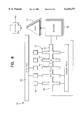
- FIG. 2 is a detailed diagram showing the components of the card reader.
- FIG. 3 is a chart of the signals generated by the card reader.
- FIG. 4(a) is a bottom view of a magnetic card in accordance with a second embodiment of the invention.
- FIG. 4(b) is a top view of a magnetic card reader used in connection with the second embodiment of the invention.
- FIG. 4(c) is a circuit diagram showing the electronic operation of the card reader.
- FIG. 5 is a side view of the magnetic card of FIG. 4(a), together with the card reader of FIG. 4(b).
- FIG. 6 shows the Hall sensor array for the magnetic card reader of FIG. 4(b).
- FIG. 7 is a block diagram of the magnetic card reader.
- FIG. 8 shows a card reader for reading information from both magnetic and smart cards in accordance with a third embodiment of the invention.
- FIG. 9 is a cut-away side view of a card having both a Hall sensor array and a magnetic strip in accordance with a fourth embodiment of the invention.
- FIG. 10 is cut-away side view of the card of FIG. 9 showing magnetic field lines generated by the magnetic strip.
- FIG. 11 is an alternative embodiment of the Hall sensor array having an RC delay circuit.
- FIG. 13 is a circuit diagram for the amplifier.
- FIG. 14 is a circuit diagram for the logic circuit.
- FIG. 15 is a diagram of the transition, magnetic field lines and resulting pulses generated by the Hall sensor array.
- FIG. 1 shows a magnetic card reader 10 used with a conventional credit card 12 having a magnetic strip.
- the credit card 12 is passed or "swiped” through the reader 10 in the direction of the arrow A.
- the reader 10 generally comprises an inductive pickup head 16 having a coil 18, a modulator 20, amplifier 22 and speaker 24.
- the magnetic strip 14 passes the inductive pickup head 16.
- the inductive head 16 reads information from the magnetic strip 14 of the card 12 as it is passed through the slot of reader 10.
- Information is stored in the magnetic strip 14 by the use of magnetic transitions.
- a transition in the magnetic direction of the strip 14 represents binary 0's and 1's.
- the inductive read head 16 As the card 12 moves past the inductive read head 16, magnetic transitions representing binary data induce a small voltage in the coil 18 of the head 16. The voltage from the coil 18 stimulates the modulator 20 to produce a short burst of audio frequency signal.
- the audio frequency signal is amplified by audio amplifier 22 and sent to the speaker 24.
- the speaker 24 is preferably located on the bottom of the reader 10 (of FIG. 1), so that it may be held in close proximity to the microphone of a telephone, for instance.
- the audio frequency signal is then transmitted electronically over telephone lines to a remote receiver (not shown).
- the inductive magnetic head 16 is of the type used in conventional card readers.
- the vertical component of the magnetic field, H 2 of the strip 14 varies as a function of time, FIG. 3.
- a time varying electric field, E(t) is induced in the windings 18 of the inductive head 16, which in turn are connected to modulator 20.
- Each magnetic transition signal induces the modulator 20 to emit a short burst of a fixed frequency in the audio or ultrasound frequency range, which is shown in the bottom graph of FIG. 3.
- Magnetic transitions on card 12 are shown, for instance, in FIG. 10.
- the magnetic flux flows toward the right of the page, as represented by arrow B.
- the magnetic flux changes direction and flows toward the left side of the page. Accordingly, the magnetic field H 2 is directed outward, or positive, as shown by arrow C.
- the next transition results in an inward, or negative magnetic field.
- the spacing of data bits on a magnetic card 12 is 5 mils (127 ⁇ m) between transitions for a binary zero and 2.5 mils (63.5 ⁇ m) for binary one.
- the transition points for each 2.5 mils are indicated in FIG. 3 by the vertical dashed lines.
- the magnetic flux is reversed, resulting in a positive magnetic field.
- the next transition results in a negative magnetic field, and the magnetic field continues to flip flop until the fourth transition point.
- the magnetic flux does not reverse, which is represented by the absence of a magnetic field change.
- the remote receiver will recognize the time between the reversal of magnetic field to indicate either a binary one or zero. As the magnetic field Hz changes, so does the output of the inductive head 16 E(t) and the short bursts of sound produced by the speaker 24.
- the frequency of the signal from the modulator 20 can be in the audio or ultrasound range provided the telephone receiver and lines have sufficient bandwidth to carry the high frequency.
- a preferred frequency in the audible range is about 1 kHz, though any suited audible frequency may be used, such as in the range of 400-4,000 Hz.
- a preferred frequency in the ultrasound range is about 40 kHz, though any suited ultrasound frequency may used, such as in the range from 30 to 40 kHz.
- Any suited signal may be used, such as a DTMF signal. However, a DTMF signal may be obstructed by the presence of a filter.
- the short bursts from the modulator 20 at a fixed frequency are then amplified by amplifier 22.
- the amplification is at about 100 mV, or 3 to 100 times amplification of the input signal.
- the amplified signal is then sent to loudspeaker 24, which emits a series of sound pulses corresponding to the magnetic transitions on the card 12.
- the sound reaches a microphone (not shown) of a telephone, for instance, which converts the sound pulses to electrical pulses that are sent electronically or telephonically to the remote receiver or to any system that is capable of receiving like signals.
- the remote receiver is comprised of a filter that selectively passes the electrical pulses corresponding to the preselected frequency of the sound pulses.
- the short pulses are detected and converted to a series of electrical pulses similar to the original electrical pulses from the inductive head.
- the pulses are read and recorded using conventional software and computer interface that are used with a conventional magnetic card reader.
- the card number, expiration data and card holder's name are preferably sent over the telephone line by the card holder.
- the information can be verified by the bank that issued the credit card and the approval sent to the merchant. This method allows the card holder to make remote transactions without exposing the card number or other information to the merchant. Furthermore, the information cannot be overheard by third parties that might otherwise be in a position to hear the conversation between the card holder and the merchant. This provides better security for the information.
- a computer microphone calling card or a telephone calling card would permit use of a conventional telephone without dialing code numbers which can be overheard and remembered by a nearby observer. Moreover, it is not necessary for the account number or expiration data to be printed on the card at all. Thus, lost and stolen cards could not be used by an unauthorized user other than by a direct transaction with a merchant. In this regard, it is preferred that the user keep the card separate from the card reader.
- the invention has particular advantages with cards requiring the entry of a PIN number to activate access to confidential information.
- the card reader may also be provided with a separate authorization code that must be entered by the user to read the card and transmit the sound signals.
- the invention may also be used, for instance, for parking garage and door access control.
- the information from a card can be transmitted from a loudspeaker of the card reader to a microphone location on the door.
- Hall sensor arrays have been used, for instance in U.S. Pat. No. 5,543,988 to Brady et al. which is herein incorporated by reference, to sense magnetic fields.
- the Hall sensor array 34 of the present invention is preferably fabricated by etching a thin film of a suitable material with a large Hall effect using photo lithographic patterning.
- the spacing of data bits on a magnetic card 36 is 5 mils (127 ⁇ m) between transitions for a binary zero and 2.5 mils (63.5 ⁇ m) for binary one.
- the individual Hall sensors 42 in the array 34 are located on 10 to 20 ⁇ m centers to provide sufficient resolution in transmission spacing to distinguish 1's and 0's.
- the sensors 42 are equally spaced and perpendicular to the central connecting bar.
- the Hall sensors 42 are each connected to a common voltage line and one of the sensors 42 is cross activated by transmitting a current through it, as indicated by arrow E.
- the sensors 42 are each approximately 10 ⁇ m wide.
- FIG. 5 shows the relationship between the contact pads 32 and conductor bar 40, as well as between the Hall sensor array 34 and the magnetic strip 38.
- the conductor bar 40 and contact pads 32 are located so that they align with each other. In this position, the Hall sensor array 34 is also aligned with the magnetic strip 38.
- the conductor bar 40 When the card reader 30 and card 36 are pressed together with the proper orientation, the conductor bar 40 is brought into contact with the two contact pads 32. The conductor bar 40 completes a circuit in the reader 30 through the contact pads 32, turning on the power supply of the reader 30. Current is then supplied to the Hall sensor array 34 and amplifier 48. Hence, the conductor bar 40 not only operates to align the magnetic strip 38 with the Hall sensor array 34, but to activate the reader 30 to generate the sound signal.
- a "wake-up" circuit is activated that turns on the power for sufficient time (100 msec to 1 sec) to send the data stream repeatedly.
- the reader 30 may then automatically be powered down, or may enter a sleep state. When the card 36 and reader 30 are separated, the circuit is broken by the loss of contact between conductor bar 40 and contact pads 32, and the reader 30 is turned off.
- the circuit diagram shows the "power up” circuit, and the relationship between the conductor bar 40 and contact pads 32.
- the battery V E connects to the circuit to charge the capacitor and induce a current I E to operate the transistor.
- the transistor acts as a switch that connects the second battery V c that in turn induces current I c and operates the device.
- the sides of the reader 30 have a C-shape defining elongated slots.
- the card 36 may then easily be aligned with the reader 30 by sliding the card 36 into the slots.
- the C-shaped configuration also facilitates storing the card 36 in the reader 30 during periods of non-use. In order to de-activate the reader 30 while not in use, the card 36 need simply be turned over or be inserted in a reverse direction so that the conductor bar 40 does not contact the contact pads 32.
- the conductor bar 40 is preferably in the form of a thin film of an electrical conductor, such as a metal film on a polymer foil substrate to provide a flexible electrically conductive strip. Alternatively, a metal foil may be used.
- the bar 40 is further provided with an adhesive backing.
- any magnetic card 36 can be adapted to be used with the card reader 30 simply by placing the conductive strip 40 at the proper position on the card. In new cards, a rectangular bar of metal foil can be molded into the back of the card in the appropriate position.
- the Hall sensor array 34 requires a current in order to produce an electric field E z perpendicular to the plane defined by the direction of current flow and the magnetic field direction. As shown in FIG. 7, a delay line 44 is used to control the flow of current to the individual Hall sensors 42 in the array 34 so the sensors 42 are activated in a sequential manner.
- the output of the array 34 thus has a time dependence which simulates the time dependent signal produced by a conventional inductive head card reader, such as shown in the embodiment of FIGS. 1-2.
- the delay line 44 is used to control current sources 46 so that the Hall sensors 42 in the array 34 are activated sequentially.
- the Hall voltage at the ends of the sensor array 34 has a time dependence similar to that of a conventional inductive head magnetic card reader.
- the delay line 44 can be activated repeatedly so the information content of the card is read many times for error correction.
- the delay line 44 preferably comprises parallel shift registers that are clocked by a common source. Each Hall sensor cross is associated with one shift register to operate as a first-in-first-out (FIFO) memory. Accordingly, the data stream provides a voltage pulse at Gate 1 at t 1 , at Gate 2 at t 2 , etc., in order to provide a current pulse through Hall cross 1 at t 1 , Hall cross 2 at t 2 , and so forth.
- FIFO first-in-first-out
- Current sources 46 preferably comprise monolithic MOS switches that are used as gates.
- the base is connected to the delay control line, and the remaining ends are connected to the power supply and Hall sensor array.
- the signal output from the Hall sensor array 34 can thus be received and processed by the same hardware and software as is used in existing card readers that are hard wired to telephone lines.
- the output voltage from the Hall sensor array 34 is amplified by amplifier 48 and transmitted as a sound signal by a loudspeaker 50 or similar transducer of electrical signals to sound waves.
- the loudspeaker 50 is preferably located in proximity to the mouth piece of a telephone to send the confidential information to a remote location.
- the speaker 50 would be located on the reverse side of the reader 30 so as to be readily accessible to the telephone microphone.
- the reader 30 is approximately the size and shape of a credit card.
- a thin format, thin film type battery (not shown) is used to provide the current for the Hall sensor array 34, delay line 44, amplifier 48 and the loudspeaker 50.
- the Hall sensors are preferably made of a semiconductor, such as silicon, germanium or indium antimonide.
- a semiconductor such as silicon, germanium or indium antimonide.
- the Hall coefficient of semiconductors is small unless they are high quality signal crystals.
- Ferromagnetic metals in the form of thin films with amorphous structure have been shown to have a large Hall coefficient at magnetic saturation.
- the amorphous magnetic films can be easily deposited onto polymer substrates by vacuum evaporation, sputtering or electroless or electrodeposition.
- the Hall sensors of amorphous magnetic material produce a large Hall voltage in a small magnetic field if they have a perpendicular easy axis magnetic anisotropy. Such films saturate in a small magnetic field perpendicular to the plane of the film. Magnetic anisotropy can be induced in amorphous magnetic materials during the deposition process.
- the deposited films are patterned into a linear array of Hall crosses by lithographic processing. Photolithography is commonly practiced in the electronics industry to pattern thin films of metals used for conductors on semiconductor and magnetic devices.
- the information stored on the magnetic strip 38 consists of a pattern of magnetized regions 25 ⁇ m wide by 3 mm long arranged perpendicular to the long axis of the strip.
- the spacing between these magnetized regions is 127 ⁇ m for binary zero and 63.5 ⁇ m for binary one.
- the Hall sensor array 34 therefore, places a Hall sensor 42, which is about 10 ⁇ m wide, at 20 ⁇ m spacing in order to pick up the field lines 66 (FIG. 10) generated from the transitions 68 on the magnetic strip 38.
- a total of 4000 Hall crosses 42 are needed in the linear array 34 to cover the 80 mm length magnetic strip 38 of a typical magnetic card 36.
- the Hall sensors 42 respond to the vertical or Z-component of the magnetic field of a magnetic bit, as does a conventional inductive pickup head in a magnetic card reader. As current passes through the Hall sensor 42, the current is affected by the field lines 66 generated by transitions 68. If a transition 68 occurs, a voltage will result on voltage lead lines 56.
- an array of magnetoresistive sensors can be used in place of the Hall sensors.
- the magnetoresistive sensors respond most efficiently to the in-plane or X and Y components of the magnetic field of a magnetic bit.
- the decoding software for recognizing "1's” and "0's” would have to be modified to detect magnetic transition from the X-Y field changes.
- the magnetoresistive sensor In order to sense the Z component, the magnetoresistive sensor would have to be oriented with the plane of the thin film sensor perpendicular to the surface of the magnetic strip.
- a sensor array of this type cannot be made by a simple lithographic patterning and etching process.
- the card reader 30 generally comprises a Hall sensor array 34, delay line 44, current control sources 46, amplifier 48, logic 52 and contact 54.
- the control of the Hall sensor array 34 is the same as for FIG. 7. Now, however, the amplified signal is processed by a logic circuit 52 that outputs a signal in the format used by an electronic smart card at contact point 54.
- the smart card reader (not shown) interfaces with reader 30 at contact 54.
- the present embodiment converts information read from a magnetic card to a smart card data format. This magnetic card to smart card data converter makes it possible for holders of magnetic cards to carry out transactions on smart card reader devices.
- FIGS. 7 and 8 may be combined into a single reader having a speaker 50 (FIG. 7), as well as logic circuit 52 and contact 54 (FIG. 8). This combined reader is then able to output information read from a magnetic card in both sound as well as smart card format.
- the amplifier 48 would simply be connected to both the speaker 50 and to the logic circuit 52.
- FIGS. 9 and 10 show another embodiment of the invention consisting of a Hall array card reader and a magnetic data storage card combined into a single card/reader 60.
- the card/reader 60 has both a magnetic strip 62 and a Hall sensor film 64.
- the card 60 is provided with an amplifier and speaker device for transmission of data by sound as well as "smart card” type electronic data readout.
- the combined card/reader 60 provides transmission of data by sound as well as compatibility with a smart card electronic reader.
- the card 60 is constructed by depositing a Hall sensor array 64 on a polymer substrate that is laminated to the back of the polymer substrate supporting the magnetic strip 62.
- FIG. 10 shows the magnetic field 66 distribution near a magnetic bit or transition 68. The vertical component of the magnetic field 66 passes through the polymer and is sensed by the Hall sensors in the array 64.
- FIG. 15 is a more detailed diagram of the relationship between the individual Hall crosses (marked with an X), the magnetic data bits or transitions (represented by the arrows) and the field lines.
- the Hall sensors are only sensitive to the up or down field components.
- the spacing of the Hall crosses (20 ⁇ m) is smaller than the spacing between the transitions (63.5 ⁇ m for ones and 127 ⁇ m for zeros).
- the small V H pulses are due to whether the Hall crosses are directly aligned with the transition points, or slightly offset.
- the thin film battery, delay line circuitry and semiconductor integrated circuit are all laminated into the card 60.
- the circuitry can be powered from the electronic connection between the card 60 and the electronic reader.
- a small contact switch may be used to activate the battery for transmission of data by sound.
- the card 60 of the present embodiment can also function as a magnetic smart card.
- a magnetic inductive write head is provided at the card reader. After an electronic transaction is completed, updated information can be written on the magnetic strip 62 by activating the write head. For example, an account balance or the remaining value of a money card can be entered as the card is removed from the smart card reader.
- the recorded information is nonvolatile, as is all magnetic storage media, so the information can always be retrieved either magnetically or electronically.
- FIG. 11 shows an alternative embodiment of the Hall sensor array 70 incorporating an RC delay circuit.
- the array 70 has Hall sensors 72, capacitors 74, current lead lines 76 and voltage lead lines 78.
- the array 70 is configured to maximize the current passing through the Hall sensor 72 from the top current lead line 76 to the bottom lead line 76, while at the same time allowing voltage to be recognized at voltage lead lines 78.
- the present invention reduces the loss of current by coating the current leads 76 with a better conductor material than the voltage lead lines 78 and the lines connecting the Hall sensors 72.
- the better conductor material enhances the flow of current in the Y-direction.
- current flow is guided from the top current lead 76, through the Hall sensor, to the bottom current lead 76.
- FIG. 12 A preferred circuit diagram is shown in FIG. 12, where 1/2 R2 represents the Hall sensor 72.
- the value for R2 is approximately 100 times that of R1, so that the current in the Y-direction, across the sensor 72, i.sub., is much greater than the current in the X-direction, i x .
- the Hall sensor 72 preferably consists of an amorphous alloy film: Co 85 atomic%, Gd 15 atomic%.
- the film thickness is about 0.1 ⁇ m having an electrical resistivity of about 100 ⁇ /cm.
- the enhanced conductive material is preferably a crystalline Cu film having a thickness of 1.0 ⁇ m and a resistivity of 10 ⁇ /cm.
- FIG. 13 shows the preferred embodiment of the amplifier 48 used in the embodiments of FIGS. 7 and 8 in greater detail.
- the amplifier 48 comprises a common emitter circuit, in which V Hall represents the voltage to the Hall sensor array and V sp represents the voltage to the speaker.
- the Hall voltage V H when added to the bias voltage from the 5V battery, causes the narrow base region (B) to conduct holes.
- the current flowing through the 500 ⁇ resistor causes a voltage drop across the resistor which drives the speaker.
- the Hall voltage signal is amplified because a small change in base-emitter voltage (B-E) near the threshold causes a large change in current in the emitter-collector (E-C) circuit.
- FIG. 14 represents the preferred embodiment for the logic circuit 52 of FIG. 8.
- the logic is a microprocessor unit, system clock, analog-to-digital (A/D) converter and a comparator circuit.
- the output of the microprocessor is in the form of digital data having conventional format for smart cards.
- the card reader may be used to generate sound signals corresponding to information read from an electronic smart card.
- the reader may be solar powered. Therefore, it is not desired to limit the invention to the specific examples disclosed or the exact construction and operation shown and described. Rather, all suitable modifications and equivalents may be resorted to, falling within the scope of the invention.
Abstract
Description
Claims (19)
Priority Applications (8)
| Application Number | Priority Date | Filing Date | Title |
|---|---|---|---|
| US09/127,812 US6129277A (en) | 1998-08-03 | 1998-08-03 | Card reader for transmission of data by sound |
| DE69918835T DE69918835D1 (en) | 1998-08-03 | 1999-08-03 | CARD READER FOR TRANSMITTING DATA THROUGH TONES |
| AT99941963T ATE271740T1 (en) | 1998-08-03 | 1999-08-03 | CARD READER FOR TRANSMITTING DATA THROUGH SOUNDS |
| PCT/US1999/016697 WO2000008772A2 (en) | 1998-08-03 | 1999-08-03 | Card reader for transmission of data by sound |
| AU55434/99A AU5543499A (en) | 1998-08-03 | 1999-08-03 | Card reader for transmission of data by sound |
| EP99941963A EP1101184B1 (en) | 1998-08-03 | 1999-08-03 | Card reader for transmission of data by sound |
| US09/592,607 US6481623B1 (en) | 1998-08-03 | 2000-06-12 | Card reader for transmission of data by sound |
| US09/902,623 US6579728B2 (en) | 1998-08-03 | 2001-07-12 | Fabrication of a high resolution, low profile credit card reader and card reader for transmission of data by sound |
Applications Claiming Priority (1)
| Application Number | Priority Date | Filing Date | Title |
|---|---|---|---|
| US09/127,812 US6129277A (en) | 1998-08-03 | 1998-08-03 | Card reader for transmission of data by sound |
Related Child Applications (1)
| Application Number | Title | Priority Date | Filing Date |
|---|---|---|---|
| US09/592,607 Continuation-In-Part US6481623B1 (en) | 1998-08-03 | 2000-06-12 | Card reader for transmission of data by sound |
Publications (1)
| Publication Number | Publication Date |
|---|---|
| US6129277A true US6129277A (en) | 2000-10-10 |
Family
ID=22432075
Family Applications (2)
| Application Number | Title | Priority Date | Filing Date |
|---|---|---|---|
| US09/127,812 Expired - Fee Related US6129277A (en) | 1998-08-03 | 1998-08-03 | Card reader for transmission of data by sound |
| US09/592,607 Expired - Fee Related US6481623B1 (en) | 1998-08-03 | 2000-06-12 | Card reader for transmission of data by sound |
Family Applications After (1)
| Application Number | Title | Priority Date | Filing Date |
|---|---|---|---|
| US09/592,607 Expired - Fee Related US6481623B1 (en) | 1998-08-03 | 2000-06-12 | Card reader for transmission of data by sound |
Country Status (6)
| Country | Link |
|---|---|
| US (2) | US6129277A (en) |
| EP (1) | EP1101184B1 (en) |
| AT (1) | ATE271740T1 (en) |
| AU (1) | AU5543499A (en) |
| DE (1) | DE69918835D1 (en) |
| WO (1) | WO2000008772A2 (en) |
Cited By (104)
| Publication number | Priority date | Publication date | Assignee | Title |
|---|---|---|---|---|
| WO2002047019A1 (en) * | 2000-12-08 | 2002-06-13 | Silverman Martin S | Dynamic virtual magnetic stripe |
| US20020079888A1 (en) * | 2000-12-27 | 2002-06-27 | Koninklijke Philips Electronics N.V. | Displacement device |
| US6579728B2 (en) * | 1998-08-03 | 2003-06-17 | Privicom, Inc. | Fabrication of a high resolution, low profile credit card reader and card reader for transmission of data by sound |
| US20030192948A1 (en) * | 2002-04-11 | 2003-10-16 | Yasuo Izuyama | Magnetic head of magnetic reader |
| US20040026506A1 (en) * | 2002-08-06 | 2004-02-12 | Alan Finkelstein | Financial transaction card with sound recording |
| US20040026495A1 (en) * | 2002-08-06 | 2004-02-12 | Alan Finkelstein | Transaction card with annunciator |
| WO2004013804A1 (en) * | 2002-08-06 | 2004-02-12 | Lenscard U.S., Llc | Transaction card with annunciator |
| US20040035942A1 (en) * | 2001-12-07 | 2004-02-26 | Silverman Martin S. | Dynamic virtual magnetic stripe |
| US20050230960A1 (en) * | 2004-03-29 | 2005-10-20 | Bilodeau Wayne L | Security label, secured article and method for making the label and article |
| US20070288371A1 (en) * | 2006-05-25 | 2007-12-13 | Johnson Aratha M | Personal electronic payment system and related method |
| US20080126259A1 (en) * | 2003-08-07 | 2008-05-29 | Thomas Richard Lowman | System and method for providing signal compatability |
| US20090159682A1 (en) * | 2007-12-24 | 2009-06-25 | Dynamics Inc. | Cards and devices with multi-function magnetic emulators and methods for using same |
| US20100108762A1 (en) * | 2009-06-10 | 2010-05-06 | Morley Jr Robert E | Card reader device for a cell phone and method of use |
| US20100314446A1 (en) * | 2009-06-10 | 2010-12-16 | Morley Jr Robert E | Card reader device and method of use |
| US20110084140A1 (en) * | 2009-10-13 | 2011-04-14 | Sam Wen | Systems and methods for decoding card swipe signals |
| US7959769B2 (en) | 2004-12-08 | 2011-06-14 | Infinite Power Solutions, Inc. | Deposition of LiCoO2 |
| US7967214B2 (en) | 2006-12-29 | 2011-06-28 | Solicore, Inc. | Card configured to receive separate battery |
| US7993773B2 (en) | 2002-08-09 | 2011-08-09 | Infinite Power Solutions, Inc. | Electrochemical apparatus with barrier layer protected substrate |
| US8021778B2 (en) | 2002-08-09 | 2011-09-20 | Infinite Power Solutions, Inc. | Electrochemical apparatus with barrier layer protected substrate |
| US8062708B2 (en) | 2006-09-29 | 2011-11-22 | Infinite Power Solutions, Inc. | Masking of and material constraint for depositing battery layers on flexible substrates |
| US8181879B2 (en) | 2006-12-29 | 2012-05-22 | Solicore, Inc. | Mailing apparatus for powered cards |
| US8197781B2 (en) | 2006-11-07 | 2012-06-12 | Infinite Power Solutions, Inc. | Sputtering target of Li3PO4 and method for producing same |
| US8235287B2 (en) | 2010-10-13 | 2012-08-07 | Square, Inc. | Read head device with slot configured to reduce torque |
| US8236443B2 (en) | 2002-08-09 | 2012-08-07 | Infinite Power Solutions, Inc. | Metal film encapsulation |
| US8260203B2 (en) | 2008-09-12 | 2012-09-04 | Infinite Power Solutions, Inc. | Energy device with integral conductive surface for data communication via electromagnetic energy and method thereof |
| US8268488B2 (en) | 2007-12-21 | 2012-09-18 | Infinite Power Solutions, Inc. | Thin film electrolyte for thin film batteries |
| US8281998B2 (en) | 2009-02-10 | 2012-10-09 | 4361423 Canada Inc. | Apparatus and method for commercial transactions using a communication device |
| US8302860B2 (en) | 2010-10-13 | 2012-11-06 | Square, Inc. | Read head device with narrow card reading slot |
| US8350519B2 (en) | 2008-04-02 | 2013-01-08 | Infinite Power Solutions, Inc | Passive over/under voltage control and protection for energy storage devices associated with energy harvesting |
| US8394522B2 (en) | 2002-08-09 | 2013-03-12 | Infinite Power Solutions, Inc. | Robust metal film encapsulation |
| US8404376B2 (en) | 2002-08-09 | 2013-03-26 | Infinite Power Solutions, Inc. | Metal film encapsulation |
| US8431264B2 (en) | 2002-08-09 | 2013-04-30 | Infinite Power Solutions, Inc. | Hybrid thin-film battery |
| US8445130B2 (en) | 2002-08-09 | 2013-05-21 | Infinite Power Solutions, Inc. | Hybrid thin-film battery |
| US8500018B2 (en) | 2010-10-13 | 2013-08-06 | Square, Inc. | Systems and methods for financial transaction through miniaturized card reader with decoding on a seller's mobile device |
| US8508193B2 (en) | 2008-10-08 | 2013-08-13 | Infinite Power Solutions, Inc. | Environmentally-powered wireless sensor module |
| US8518581B2 (en) | 2008-01-11 | 2013-08-27 | Inifinite Power Solutions, Inc. | Thin film encapsulation for thin film batteries and other devices |
| US8571989B2 (en) | 2010-10-13 | 2013-10-29 | Square, Inc. | Decoding systems with a decoding engine running on a mobile device and coupled to a social network |
| US8573489B2 (en) | 2010-10-13 | 2013-11-05 | Square, Inc. | Decoding systems with a decoding engine running on a mobile device with a touch screen |
| US8573486B2 (en) | 2010-10-13 | 2013-11-05 | Square, Inc. | Systems and methods for financial transaction through miniaturized card reader with confirmation of payment sent to buyer |
| US8573487B2 (en) | 2010-10-13 | 2013-11-05 | Square, Inc. | Integrated read head device |
| US8579203B1 (en) * | 2008-12-19 | 2013-11-12 | Dynamics Inc. | Electronic magnetic recorded media emulators in magnetic card devices |
| US8599572B2 (en) | 2009-09-01 | 2013-12-03 | Infinite Power Solutions, Inc. | Printed circuit board with integrated thin film battery |
| US8602305B2 (en) | 2010-10-13 | 2013-12-10 | Square, Inc. | Decoding systems with a decoding engine running on a mobile device configured to be coupled and decoupled to a card reader with wake-up electronics |
| US8612352B2 (en) | 2010-10-13 | 2013-12-17 | Square, Inc. | Decoding systems with a decoding engine running on a mobile device and coupled to a payment system that includes identifying information of second parties qualified to conduct business with the payment system |
| US8615445B2 (en) | 2002-02-05 | 2013-12-24 | Square, Inc. | Method for conducting financial transactions |
| US8636876B2 (en) | 2004-12-08 | 2014-01-28 | R. Ernest Demaray | Deposition of LiCoO2 |
| US8640953B2 (en) | 2010-10-13 | 2014-02-04 | Square, Inc. | Decoding system running on a mobile device and coupled to a payment system that includes at least one of, a user database, a product database and a transaction database |
| US8662389B2 (en) | 2010-10-13 | 2014-03-04 | Square, Inc. | Payment methods with a payment service and tabs selected by a first party and opened by a second party at any geographic location of the first party's mobile device |
| US8678277B2 (en) | 2010-10-13 | 2014-03-25 | Square, Inc. | Decoding system coupled to a payment system that includes a cryptographic key |
| US8701997B2 (en) | 2010-10-13 | 2014-04-22 | Square, Inc. | Decoding systems with a decoding engine running on a mobile device and using financial transaction card information to create a send funds application on the mobile device |
| US8701996B2 (en) | 2010-10-13 | 2014-04-22 | Square, Inc. | Cost effective card reader and methods to be configured to be coupled to a mobile device |
| US8728285B2 (en) | 2003-05-23 | 2014-05-20 | Demaray, Llc | Transparent conductive oxides |
| US8870070B2 (en) | 2010-10-13 | 2014-10-28 | Square, Inc. | Card reader device |
| US8870071B2 (en) | 2010-10-13 | 2014-10-28 | Square, Inc. | Read head device with selected sampling rate |
| US8876003B2 (en) | 2010-10-13 | 2014-11-04 | Square, Inc. | Read head device with selected output jack characteristics |
| US8906523B2 (en) | 2008-08-11 | 2014-12-09 | Infinite Power Solutions, Inc. | Energy device with integral collector surface for electromagnetic energy harvesting and method thereof |
| US9016572B2 (en) | 2010-10-13 | 2015-04-28 | Square, Inc. | Systems and methods for financial transaction through miniaturized card with ASIC |
| US9195454B2 (en) | 2013-11-27 | 2015-11-24 | Square, Inc. | Firmware management |
| US9224142B2 (en) | 2002-02-05 | 2015-12-29 | Square, Inc. | Card reader with power efficient architecture that includes a power supply and a wake up circuit |
| US9230143B2 (en) | 2013-12-11 | 2016-01-05 | Square, Inc. | Bidirectional audio communication in reader devices |
| US9256769B1 (en) | 2014-02-25 | 2016-02-09 | Square, Inc. | Mobile reader device |
| US9256770B1 (en) | 2014-07-02 | 2016-02-09 | Square, Inc. | Terminal case with integrated reader and shortened base |
| US9262757B2 (en) | 2002-02-05 | 2016-02-16 | Square, Inc. | Method of transmitting information from a card reader with a power supply and wake-up circuit to a mobile device |
| US9262777B2 (en) | 2002-02-05 | 2016-02-16 | Square, Inc. | Card reader with power efficient architecture that includes a wake-up circuit |
| US9286635B2 (en) | 2002-02-05 | 2016-03-15 | Square, Inc. | Method of transmitting information from efficient communication protocol card readers to mobile devices |
| US9305314B2 (en) | 2002-02-05 | 2016-04-05 | Square, Inc. | Methods of transmitting information to mobile devices using cost effective card readers |
| US9324100B2 (en) | 2002-02-05 | 2016-04-26 | Square, Inc. | Card reader with asymmetric spring |
| US9334557B2 (en) | 2007-12-21 | 2016-05-10 | Sapurast Research Llc | Method for sputter targets for electrolyte films |
| US9355285B1 (en) | 2015-02-12 | 2016-05-31 | Square, Inc. | Tone-based wake up circuit for card reader |
| USD762651S1 (en) | 2014-06-06 | 2016-08-02 | Square, Inc. | Mobile device case |
| US9436955B2 (en) | 2009-06-10 | 2016-09-06 | Square, Inc. | Methods for transferring funds using a payment service where financial account information is only entered once with a payment service and need not be re-entered for future transfers |
| US9454866B2 (en) | 2010-10-13 | 2016-09-27 | Square, Inc. | Method of conducting financial transactions where a payer's financial account information is entered only once with a payment system |
| US9495676B2 (en) | 2002-02-05 | 2016-11-15 | Square, Inc. | Method of transmitting information from a power efficient card to a mobile device |
| US9495675B2 (en) | 2002-02-05 | 2016-11-15 | Square, Inc. | Small card reader configured to be coupled to a mobile device |
| US9576159B1 (en) | 2011-01-24 | 2017-02-21 | Square, Inc. | Multiple payment card reader system |
| US9582795B2 (en) | 2002-02-05 | 2017-02-28 | Square, Inc. | Methods of transmitting information from efficient encryption card readers to mobile devices |
| US9633236B1 (en) | 2013-12-11 | 2017-04-25 | Square, Inc. | Power harvesting in reader devices |
| US9634296B2 (en) | 2002-08-09 | 2017-04-25 | Sapurast Research Llc | Thin film battery on an integrated circuit or circuit board and method thereof |
| US9760740B1 (en) | 2014-06-23 | 2017-09-12 | Square, Inc. | Terminal case with integrated dual reader stack |
| US9799025B2 (en) | 2014-08-19 | 2017-10-24 | Square, Inc. | Energy harvesting bidirectional audio interface |
| US9916581B2 (en) | 2002-02-05 | 2018-03-13 | Square, Inc. | Back end of payment system associated with financial transactions using card readers coupled to mobile devices |
| US10304043B1 (en) | 2014-05-21 | 2019-05-28 | Square, Inc. | Multi-peripheral host device |
| US10373144B1 (en) | 2015-05-13 | 2019-08-06 | Square, Inc. | Transaction payment processing by multiple data centers |
| US10402807B1 (en) | 2017-02-28 | 2019-09-03 | Square, Inc. | Estimating interchange fees for card payments |
| US10402798B1 (en) | 2014-05-11 | 2019-09-03 | Square, Inc. | Open tab transactions |
| US10410021B1 (en) | 2017-12-08 | 2019-09-10 | Square, Inc. | Transaction object reader with digital signal input/output and internal audio-based communication |
| US10410200B2 (en) | 2016-03-15 | 2019-09-10 | Square, Inc. | Cloud-based generation of receipts using transaction information |
| US10504093B1 (en) | 2014-05-06 | 2019-12-10 | Square, Inc. | Fraud protection based on presence indication |
| US10560808B2 (en) | 2013-07-23 | 2020-02-11 | Square, Inc. | Computing distances of devices |
| US10592903B2 (en) | 2011-11-22 | 2020-03-17 | Square, Inc. | Authorization of cardless payment transactions |
| US10628811B2 (en) | 2016-03-15 | 2020-04-21 | Square, Inc. | System-based detection of card sharing and fraud |
| US10636019B1 (en) | 2016-03-31 | 2020-04-28 | Square, Inc. | Interactive gratuity platform |
| US10680277B2 (en) | 2010-06-07 | 2020-06-09 | Sapurast Research Llc | Rechargeable, high-density electrochemical device |
| US10692088B1 (en) | 2014-02-18 | 2020-06-23 | Square, Inc. | Performing actions based on the location of a mobile device during a card swipe |
| US10783531B2 (en) | 2012-03-16 | 2020-09-22 | Square, Inc. | Cardless payment transactions based on geographic locations of user devices |
| USD905059S1 (en) | 2018-07-25 | 2020-12-15 | Square, Inc. | Card reader device |
| US10885522B1 (en) | 2013-02-08 | 2021-01-05 | Square, Inc. | Updating merchant location for cardless payment transactions |
| US10902406B1 (en) | 2013-03-14 | 2021-01-26 | Square, Inc. | Verifying proximity during payment transactions |
| US11087301B1 (en) | 2017-12-19 | 2021-08-10 | Square, Inc. | Tamper resistant device |
| US11436461B2 (en) | 2005-02-22 | 2022-09-06 | Kepler Computing Inc. | Mobile phone with magnetic card emulation |
| US11449854B1 (en) | 2012-10-29 | 2022-09-20 | Block, Inc. | Establishing consent for cardless transactions using short-range transmission |
| US11574296B2 (en) | 2012-08-17 | 2023-02-07 | Block, Inc. | Systems and methods for providing gratuities to merchants |
| US11587146B1 (en) | 2013-11-13 | 2023-02-21 | Block, Inc. | Wireless beacon shopping experience |
| US11803841B1 (en) | 2013-10-29 | 2023-10-31 | Block, Inc. | Discovery and communication using direct radio signal communication |
Families Citing this family (69)
| Publication number | Priority date | Publication date | Assignee | Title |
|---|---|---|---|---|
| IL127569A0 (en) | 1998-09-16 | 1999-10-28 | Comsense Technologies Ltd | Interactive toys |
| US6607136B1 (en) | 1998-09-16 | 2003-08-19 | Beepcard Inc. | Physical presence digital authentication system |
| US7334735B1 (en) * | 1998-10-02 | 2008-02-26 | Beepcard Ltd. | Card for interaction with a computer |
| US7213764B2 (en) | 2002-11-07 | 2007-05-08 | American Express Travel Related Services Company, Inc. | Foldable transaction card |
| US7347360B2 (en) | 2003-12-10 | 2008-03-25 | American Express Travel Related Services Company, Inc. | Foldable transaction card systems for non-traditionally-sized transaction cards |
| US7889052B2 (en) | 2001-07-10 | 2011-02-15 | Xatra Fund Mx, Llc | Authorizing payment subsequent to RF transactions |
| US8019609B2 (en) | 1999-10-04 | 2011-09-13 | Dialware Inc. | Sonic/ultrasonic authentication method |
| IT1311360B1 (en) * | 1999-11-15 | 2002-03-12 | Smartel S P A | INTELLIGENT MULTIFUNCTIONAL PAPER. |
| US9219708B2 (en) | 2001-03-22 | 2015-12-22 | DialwareInc. | Method and system for remotely authenticating identification devices |
| US7725427B2 (en) | 2001-05-25 | 2010-05-25 | Fred Bishop | Recurrent billing maintenance with radio frequency payment devices |
| US7705732B2 (en) | 2001-07-10 | 2010-04-27 | Fred Bishop | Authenticating an RF transaction using a transaction counter |
| US7668750B2 (en) | 2001-07-10 | 2010-02-23 | David S Bonalle | Securing RF transactions using a transactions counter |
| US9454752B2 (en) | 2001-07-10 | 2016-09-27 | Chartoleaux Kg Limited Liability Company | Reload protocol at a transaction processing entity |
| US8001054B1 (en) | 2001-07-10 | 2011-08-16 | American Express Travel Related Services Company, Inc. | System and method for generating an unpredictable number using a seeded algorithm |
| US9024719B1 (en) | 2001-07-10 | 2015-05-05 | Xatra Fund Mx, Llc | RF transaction system and method for storing user personal data |
| US20040236699A1 (en) | 2001-07-10 | 2004-11-25 | American Express Travel Related Services Company, Inc. | Method and system for hand geometry recognition biometrics on a fob |
| US8548927B2 (en) | 2001-07-10 | 2013-10-01 | Xatra Fund Mx, Llc | Biometric registration for facilitating an RF transaction |
| US7735725B1 (en) | 2001-07-10 | 2010-06-15 | Fred Bishop | Processing an RF transaction using a routing number |
| US8284025B2 (en) | 2001-07-10 | 2012-10-09 | Xatra Fund Mx, Llc | Method and system for auditory recognition biometrics on a FOB |
| US9031880B2 (en) | 2001-07-10 | 2015-05-12 | Iii Holdings 1, Llc | Systems and methods for non-traditional payment using biometric data |
| US6805287B2 (en) | 2002-09-12 | 2004-10-19 | American Express Travel Related Services Company, Inc. | System and method for converting a stored value card to a credit card |
| JP3975918B2 (en) * | 2002-09-27 | 2007-09-12 | ソニー株式会社 | Antenna device |
| US20100145818A1 (en) * | 2002-09-30 | 2010-06-10 | Ifedayo Udiani | Electronic Credit/Debit Cardless Payment Processing System and Method PSM |
| US7137552B1 (en) | 2003-12-10 | 2006-11-21 | American Express Travel Related Services Company, Inc. | Portable electronic devices interconnected with convenient or foldable transaction cards |
| US7278584B1 (en) | 2002-11-07 | 2007-10-09 | American Express Travel Related Services Company, Inc. | Portable electronic music devices with convenient or foldable transaction cards |
| US7070095B1 (en) | 2002-11-07 | 2006-07-04 | American Express Travel Related Services Company, Inc. | Foldable transaction cards and methods of making the same |
| US7540426B1 (en) | 2002-11-07 | 2009-06-02 | American Express Travel Related Services Company, Inc. | Foldable transaction cards and methods of making the same |
| DE60333664D1 (en) * | 2002-12-11 | 2010-09-16 | American Express Travel Relate | FOLDABLE TRANSACTION CARD SYSTEMS |
| US7124955B2 (en) * | 2003-01-28 | 2006-10-24 | American Express Travel Related Services Company, Inc. | Compact or convenient transaction cards |
| EP1514166B1 (en) * | 2003-04-15 | 2012-01-11 | NDS Limited | Secure clock |
| US7721956B2 (en) | 2003-12-10 | 2010-05-25 | American Express Travel Related Services Company, Inc. | Foldable transaction card systems |
| US7318550B2 (en) | 2004-07-01 | 2008-01-15 | American Express Travel Related Services Company, Inc. | Biometric safeguard method for use with a smartcard |
| US8049594B1 (en) | 2004-11-30 | 2011-11-01 | Xatra Fund Mx, Llc | Enhanced RFID instrument security |
| US20070067833A1 (en) * | 2005-09-20 | 2007-03-22 | Colnot Vincent C | Methods and Apparatus for Enabling Secure Network-Based Transactions |
| US20070263779A1 (en) * | 2006-04-18 | 2007-11-15 | James Bradley | Device and method for simulating a telephonic condition |
| US7991158B2 (en) * | 2006-12-13 | 2011-08-02 | Tyfone, Inc. | Secure messaging |
| US20080204237A1 (en) * | 2007-02-26 | 2008-08-28 | Eduard Levin | RFID tag with security features |
| US9741027B2 (en) | 2007-12-14 | 2017-08-22 | Tyfone, Inc. | Memory card based contactless devices |
| US7961101B2 (en) | 2008-08-08 | 2011-06-14 | Tyfone, Inc. | Small RFID card with integrated inductive element |
| US8451122B2 (en) | 2008-08-08 | 2013-05-28 | Tyfone, Inc. | Smartcard performance enhancement circuits and systems |
| TWI420398B (en) | 2009-02-24 | 2013-12-21 | Tyfone Inc | Contactless device with miniaturized antenna |
| US20100243732A1 (en) * | 2009-03-25 | 2010-09-30 | George Wallner | Audio/acoustically coupled card reader |
| US9104922B2 (en) * | 2012-06-15 | 2015-08-11 | Honeywell International Inc. | Anisotropic magneto-resistance (AMR) gradiometer/magnetometer to read a magnetic track |
| US20150371234A1 (en) * | 2014-02-21 | 2015-12-24 | Looppay, Inc. | Methods, devices, and systems for secure provisioning, transmission, and authentication of payment data |
| US9324065B2 (en) | 2014-06-11 | 2016-04-26 | Square, Inc. | Determining languages for a multilingual interface |
| US11080674B1 (en) | 2014-09-19 | 2021-08-03 | Square, Inc. | Point of sale system |
| US10753982B2 (en) | 2014-12-09 | 2020-08-25 | Square, Inc. | Monitoring battery health of a battery used in a device |
| US11481750B2 (en) | 2015-06-30 | 2022-10-25 | Block, Inc. | Pairing a payment object reader with a point-of-sale terminal |
| US11080675B1 (en) | 2015-09-08 | 2021-08-03 | Square, Inc. | Point-of-sale system having a secure touch mode |
| US11087315B2 (en) | 2015-09-24 | 2021-08-10 | Square, Inc. | Server-assisted pairing for wireless communications |
| US10108412B2 (en) | 2016-03-30 | 2018-10-23 | Square, Inc. | Blocking and non-blocking firmware update |
| US10937019B2 (en) | 2016-06-08 | 2021-03-02 | Square, Inc. | Wireless communication system with auxiliary antenna |
| US11010765B2 (en) | 2016-06-29 | 2021-05-18 | Square, Inc. | Preliminary acquisition of payment information |
| US10817869B2 (en) | 2016-06-29 | 2020-10-27 | Square, Inc. | Preliminary enablement of transaction processing circuitry |
| US11871237B1 (en) | 2016-06-30 | 2024-01-09 | Block, Inc. | Pairing a payment object reader with a point-of-sale terminal |
| US10402816B2 (en) | 2016-12-31 | 2019-09-03 | Square, Inc. | Partial data object acquisition and processing |
| US10621590B2 (en) | 2017-02-22 | 2020-04-14 | Square, Inc. | Line-based chip card tamper detection |
| US10733589B2 (en) | 2017-04-28 | 2020-08-04 | Square, Inc. | Point of sale device power management and under voltage protection |
| US10949189B2 (en) | 2017-06-28 | 2021-03-16 | Square, Inc. | Securely updating software on connected electronic devices |
| US10635820B1 (en) | 2017-09-29 | 2020-04-28 | Square, Inc. | Update policy-based anti-rollback techniques |
| US11257058B1 (en) * | 2017-10-30 | 2022-02-22 | Square, Inc. | Sharing output device between unsecured processor and secured processor |
| US10970698B1 (en) * | 2017-12-08 | 2021-04-06 | Square, Inc. | Reader detection signal bypassing secure processor |
| US10762196B2 (en) | 2018-12-21 | 2020-09-01 | Square, Inc. | Point of sale (POS) systems and methods with dynamic kernel selection |
| US11049095B2 (en) | 2018-12-21 | 2021-06-29 | Square, Inc. | Point of sale (POS) systems and methods with dynamic kernel selection |
| US10990969B2 (en) | 2018-12-21 | 2021-04-27 | Square, Inc. | Point of sale (POS) systems and methods for dynamically processing payment data based on payment reader capability |
| CN112184936B (en) * | 2019-07-02 | 2023-08-29 | 鸿富锦精密电子(郑州)有限公司 | Electronic device and card swiping detection method |
| US11665817B2 (en) | 2019-09-30 | 2023-05-30 | Block, Inc. | Tamper detection based on flexible member connecting circuitry elements |
| US10810570B1 (en) | 2019-09-30 | 2020-10-20 | Square, Inc. | Point of sale device with cradle for mobile computing device |
| US11663368B2 (en) | 2019-09-30 | 2023-05-30 | Block, Inc. | Tamper detection based on removal of fastener from recess |
Citations (7)
| Publication number | Priority date | Publication date | Assignee | Title |
|---|---|---|---|---|
| US4197987A (en) * | 1977-06-02 | 1980-04-15 | Compagnie Internationale Pour L'informatique | Device for detecting magnetic fields and method of making same |
| US5524072A (en) * | 1991-12-04 | 1996-06-04 | Enco-Tone Ltd. | Methods and apparatus for data encryption and transmission |
| US5539819A (en) * | 1993-07-19 | 1996-07-23 | Bell Systems 24 Inc. | Credit card which generates a DTMF tone |
| US5561710A (en) * | 1992-11-17 | 1996-10-01 | Helms; Ramon E. | Interactive voice communication terminal with alpha and numeric keypad |
| US5636271A (en) * | 1995-06-14 | 1997-06-03 | Mci Corporation | Security code selector for telephone access card |
| US5740232A (en) * | 1994-05-06 | 1998-04-14 | France Telecom | Smart card based system for telephone-securized transactions |
| US5764742A (en) * | 1995-04-07 | 1998-06-09 | Howard; Sheldon | System for accessing telephonic communications and for conducting telephonic transactions |
Family Cites Families (21)
| Publication number | Priority date | Publication date | Assignee | Title |
|---|---|---|---|---|
| US4213039A (en) | 1978-10-16 | 1980-07-15 | Automatic Parking Devices, Inc. | Dynamic card reader |
| GB8522427D0 (en) | 1985-09-10 | 1985-10-16 | Plessey Co Plc | Credit transaction arrangments |
| JPS6310845A (en) | 1986-07-01 | 1988-01-18 | Ryokichi Tamaoki | Telephone card |
| US5229894A (en) | 1988-02-16 | 1993-07-20 | M.R. Sensors Limited | Method and apparatus for reading and decoding information using a magnetoresistive sensor |
| US4897865A (en) | 1988-04-29 | 1990-01-30 | Epic Data, Inc. | Telephone data collection device |
| FR2660776B1 (en) | 1990-04-05 | 1994-06-17 | Alain Bernard | ELECTRONIC TELEPHONE DEVICE. |
| AU8986091A (en) | 1991-01-11 | 1992-07-16 | Strategic Telecom | Access phone |
| US5144654A (en) | 1991-03-22 | 1992-09-01 | Kelley James T | Automatic telephone dialer system with printed storage |
| JPH06503218A (en) | 1991-04-16 | 1994-04-07 | バラス,ジョン | Method and apparatus for placing orders from remote locations |
| US5377263A (en) | 1991-05-01 | 1994-12-27 | Dial One Fastcard | Telephone dialer card |
| US5612528A (en) * | 1992-07-27 | 1997-03-18 | Central Research Laboratories Limited | Processing of magnetically recorded data to detect fraud |
| US5359182A (en) | 1992-10-06 | 1994-10-25 | Interdigital Technology Corporation | Wireless telephone debit card system and method |
| US5358088A (en) | 1992-11-25 | 1994-10-25 | Mars Incorporated | Horizontal magnetoresistive head apparatus and method for detecting magnetic data |
| US5455857A (en) | 1993-03-18 | 1995-10-03 | Mcguire; Sean | Automatic telephone calling card |
| US5396455A (en) | 1993-04-30 | 1995-03-07 | International Business Machines Corporation | Magnetic non-volatile random access memory |
| US5543988A (en) * | 1993-04-30 | 1996-08-06 | International Business Machines Corporation | Hall sensor with high spatial resolution in two directions concurrently |
| US5343519A (en) | 1993-09-07 | 1994-08-30 | Peter Feldman | Autodialer with pin feature |
| JPH07296332A (en) * | 1994-04-25 | 1995-11-10 | Oki Electric Ind Co Ltd | Magnetoresistance effect head and its manufacture and magnetic stripe information reader using magnetoresistance effect head |
| US5583933A (en) | 1994-08-05 | 1996-12-10 | Mark; Andrew R. | Method and apparatus for the secure communication of data |
| US5559317A (en) * | 1995-03-27 | 1996-09-24 | International Verifact Inc. | Card reader with carriage powered by movement of inserted card |
| JPH08274858A (en) | 1995-03-30 | 1996-10-18 | Kokusai Denshin Denwa Co Ltd <Kdd> | Dialless call origination equipment |
-
1998
- 1998-08-03 US US09/127,812 patent/US6129277A/en not_active Expired - Fee Related
-
1999
- 1999-08-03 DE DE69918835T patent/DE69918835D1/en not_active Expired - Fee Related
- 1999-08-03 AU AU55434/99A patent/AU5543499A/en not_active Abandoned
- 1999-08-03 AT AT99941963T patent/ATE271740T1/en not_active IP Right Cessation
- 1999-08-03 EP EP99941963A patent/EP1101184B1/en not_active Expired - Lifetime
- 1999-08-03 WO PCT/US1999/016697 patent/WO2000008772A2/en active IP Right Grant
-
2000
- 2000-06-12 US US09/592,607 patent/US6481623B1/en not_active Expired - Fee Related
Patent Citations (7)
| Publication number | Priority date | Publication date | Assignee | Title |
|---|---|---|---|---|
| US4197987A (en) * | 1977-06-02 | 1980-04-15 | Compagnie Internationale Pour L'informatique | Device for detecting magnetic fields and method of making same |
| US5524072A (en) * | 1991-12-04 | 1996-06-04 | Enco-Tone Ltd. | Methods and apparatus for data encryption and transmission |
| US5561710A (en) * | 1992-11-17 | 1996-10-01 | Helms; Ramon E. | Interactive voice communication terminal with alpha and numeric keypad |
| US5539819A (en) * | 1993-07-19 | 1996-07-23 | Bell Systems 24 Inc. | Credit card which generates a DTMF tone |
| US5740232A (en) * | 1994-05-06 | 1998-04-14 | France Telecom | Smart card based system for telephone-securized transactions |
| US5764742A (en) * | 1995-04-07 | 1998-06-09 | Howard; Sheldon | System for accessing telephonic communications and for conducting telephonic transactions |
| US5636271A (en) * | 1995-06-14 | 1997-06-03 | Mci Corporation | Security code selector for telephone access card |
Cited By (195)
| Publication number | Priority date | Publication date | Assignee | Title |
|---|---|---|---|---|
| US6579728B2 (en) * | 1998-08-03 | 2003-06-17 | Privicom, Inc. | Fabrication of a high resolution, low profile credit card reader and card reader for transmission of data by sound |
| WO2002047019A1 (en) * | 2000-12-08 | 2002-06-13 | Silverman Martin S | Dynamic virtual magnetic stripe |
| US20020079888A1 (en) * | 2000-12-27 | 2002-06-27 | Koninklijke Philips Electronics N.V. | Displacement device |
| US6661127B2 (en) * | 2000-12-27 | 2003-12-09 | Koninklijke Philips Electronics N.V. | Displacement device |
| US20040035942A1 (en) * | 2001-12-07 | 2004-02-26 | Silverman Martin S. | Dynamic virtual magnetic stripe |
| US9582795B2 (en) | 2002-02-05 | 2017-02-28 | Square, Inc. | Methods of transmitting information from efficient encryption card readers to mobile devices |
| US9495675B2 (en) | 2002-02-05 | 2016-11-15 | Square, Inc. | Small card reader configured to be coupled to a mobile device |
| US9286635B2 (en) | 2002-02-05 | 2016-03-15 | Square, Inc. | Method of transmitting information from efficient communication protocol card readers to mobile devices |
| US9262777B2 (en) | 2002-02-05 | 2016-02-16 | Square, Inc. | Card reader with power efficient architecture that includes a wake-up circuit |
| US9595033B2 (en) | 2002-02-05 | 2017-03-14 | Square, Inc. | Method of transmitting information from efficient communication protocol card |
| US10007813B2 (en) | 2002-02-05 | 2018-06-26 | Square, Inc. | Card reader with passive ID circuit |
| US10140481B2 (en) | 2002-02-05 | 2018-11-27 | Square, Inc. | Card reader with power efficient architecture that includes a power supply and a wake-up circuit |
| US9916581B2 (en) | 2002-02-05 | 2018-03-13 | Square, Inc. | Back end of payment system associated with financial transactions using card readers coupled to mobile devices |
| US9495676B2 (en) | 2002-02-05 | 2016-11-15 | Square, Inc. | Method of transmitting information from a power efficient card to a mobile device |
| US9449203B2 (en) | 2002-02-05 | 2016-09-20 | Square, Inc. | Card reader with power efficient architecture that includes a power supply and a wake-up circuit |
| US9224142B2 (en) | 2002-02-05 | 2015-12-29 | Square, Inc. | Card reader with power efficient architecture that includes a power supply and a wake up circuit |
| US9305314B2 (en) | 2002-02-05 | 2016-04-05 | Square, Inc. | Methods of transmitting information to mobile devices using cost effective card readers |
| US9858603B2 (en) | 2002-02-05 | 2018-01-02 | Square, Inc. | Card reader with power efficient architecture that includes a wake-up circuit |
| US9324100B2 (en) | 2002-02-05 | 2016-04-26 | Square, Inc. | Card reader with asymmetric spring |
| US9262757B2 (en) | 2002-02-05 | 2016-02-16 | Square, Inc. | Method of transmitting information from a card reader with a power supply and wake-up circuit to a mobile device |
| US8615445B2 (en) | 2002-02-05 | 2013-12-24 | Square, Inc. | Method for conducting financial transactions |
| US6830182B2 (en) * | 2002-04-11 | 2004-12-14 | Cis Eletronica Industria E Comercio Ltda. | Magnetic card reader |
| US20030192948A1 (en) * | 2002-04-11 | 2003-10-16 | Yasuo Izuyama | Magnetic head of magnetic reader |
| US7225994B2 (en) * | 2002-08-06 | 2007-06-05 | Innovative Card Technologies, Inc. | Financial transaction card with sound recording |
| US20040026495A1 (en) * | 2002-08-06 | 2004-02-12 | Alan Finkelstein | Transaction card with annunciator |
| US20040026506A1 (en) * | 2002-08-06 | 2004-02-12 | Alan Finkelstein | Financial transaction card with sound recording |
| WO2004013804A1 (en) * | 2002-08-06 | 2004-02-12 | Lenscard U.S., Llc | Transaction card with annunciator |
| US8021778B2 (en) | 2002-08-09 | 2011-09-20 | Infinite Power Solutions, Inc. | Electrochemical apparatus with barrier layer protected substrate |
| US8404376B2 (en) | 2002-08-09 | 2013-03-26 | Infinite Power Solutions, Inc. | Metal film encapsulation |
| US9793523B2 (en) | 2002-08-09 | 2017-10-17 | Sapurast Research Llc | Electrochemical apparatus with barrier layer protected substrate |
| US8445130B2 (en) | 2002-08-09 | 2013-05-21 | Infinite Power Solutions, Inc. | Hybrid thin-film battery |
| US9634296B2 (en) | 2002-08-09 | 2017-04-25 | Sapurast Research Llc | Thin film battery on an integrated circuit or circuit board and method thereof |
| US8236443B2 (en) | 2002-08-09 | 2012-08-07 | Infinite Power Solutions, Inc. | Metal film encapsulation |
| US8535396B2 (en) | 2002-08-09 | 2013-09-17 | Infinite Power Solutions, Inc. | Electrochemical apparatus with barrier layer protected substrate |
| US8431264B2 (en) | 2002-08-09 | 2013-04-30 | Infinite Power Solutions, Inc. | Hybrid thin-film battery |
| US7993773B2 (en) | 2002-08-09 | 2011-08-09 | Infinite Power Solutions, Inc. | Electrochemical apparatus with barrier layer protected substrate |
| US8394522B2 (en) | 2002-08-09 | 2013-03-12 | Infinite Power Solutions, Inc. | Robust metal film encapsulation |
| US8728285B2 (en) | 2003-05-23 | 2014-05-20 | Demaray, Llc | Transparent conductive oxides |
| US20080126259A1 (en) * | 2003-08-07 | 2008-05-29 | Thomas Richard Lowman | System and method for providing signal compatability |
| US20050230960A1 (en) * | 2004-03-29 | 2005-10-20 | Bilodeau Wayne L | Security label, secured article and method for making the label and article |
| US7959769B2 (en) | 2004-12-08 | 2011-06-14 | Infinite Power Solutions, Inc. | Deposition of LiCoO2 |
| US8636876B2 (en) | 2004-12-08 | 2014-01-28 | R. Ernest Demaray | Deposition of LiCoO2 |
| US11436461B2 (en) | 2005-02-22 | 2022-09-06 | Kepler Computing Inc. | Mobile phone with magnetic card emulation |
| US11720777B2 (en) | 2005-02-22 | 2023-08-08 | Icashe, Inc. | Mobile phone with magnetic card emulation |
| US20070288371A1 (en) * | 2006-05-25 | 2007-12-13 | Johnson Aratha M | Personal electronic payment system and related method |
| US8062708B2 (en) | 2006-09-29 | 2011-11-22 | Infinite Power Solutions, Inc. | Masking of and material constraint for depositing battery layers on flexible substrates |
| US8197781B2 (en) | 2006-11-07 | 2012-06-12 | Infinite Power Solutions, Inc. | Sputtering target of Li3PO4 and method for producing same |
| US8181879B2 (en) | 2006-12-29 | 2012-05-22 | Solicore, Inc. | Mailing apparatus for powered cards |
| US7967214B2 (en) | 2006-12-29 | 2011-06-28 | Solicore, Inc. | Card configured to receive separate battery |
| US8268488B2 (en) | 2007-12-21 | 2012-09-18 | Infinite Power Solutions, Inc. | Thin film electrolyte for thin film batteries |
| US9334557B2 (en) | 2007-12-21 | 2016-05-10 | Sapurast Research Llc | Method for sputter targets for electrolyte films |
| US20090159669A1 (en) * | 2007-12-24 | 2009-06-25 | Dynamics Inc. | Cards with serial magnetic emulators |
| US9547816B2 (en) | 2007-12-24 | 2017-01-17 | Dynamics Inc. | Cards and devices with multifunction magnetic emulators and methods for using same |
| US8302872B2 (en) | 2007-12-24 | 2012-11-06 | Dynamics Inc. | Advanced dynamic credit cards |
| US8424773B2 (en) | 2007-12-24 | 2013-04-23 | Dynamics Inc. | Payment cards and devices with enhanced magnetic emulators |
| US8286876B2 (en) | 2007-12-24 | 2012-10-16 | Dynamics Inc. | Cards and devices with magnetic emulators and magnetic reader read-head detectors |
| US10032100B2 (en) | 2007-12-24 | 2018-07-24 | Dynamics Inc. | Cards and devices with multifunction magnetic emulators and methods for using same |
| US20090159682A1 (en) * | 2007-12-24 | 2009-06-25 | Dynamics Inc. | Cards and devices with multi-function magnetic emulators and methods for using same |
| US9727813B2 (en) | 2007-12-24 | 2017-08-08 | Dynamics Inc. | Credit, security, debit cards and the like with buttons |
| US8517276B2 (en) | 2007-12-24 | 2013-08-27 | Dynamics Inc. | Cards and devices with multifunction magnetic emulators and methods for using same |
| US20090159696A1 (en) * | 2007-12-24 | 2009-06-25 | Dynamics Inc. | Advanced dynamic credit cards |
| US9704088B2 (en) | 2007-12-24 | 2017-07-11 | Dynamics Inc. | Cards and devices with multifunction magnetic emulators and methods for using same |
| US10169692B2 (en) | 2007-12-24 | 2019-01-01 | Dynamics Inc. | Credit, security, debit cards and the like with buttons |
| US8020775B2 (en) | 2007-12-24 | 2011-09-20 | Dynamics Inc. | Payment cards and devices with enhanced magnetic emulators |
| US10198687B2 (en) | 2007-12-24 | 2019-02-05 | Dynamics Inc. | Cards and devices with multifunction magnetic emulators and methods for using same |
| US10223631B2 (en) | 2007-12-24 | 2019-03-05 | Dynamics Inc. | Cards and devices with multifunction magnetic emulators and methods for using same |
| US8382000B2 (en) | 2007-12-24 | 2013-02-26 | Dynamics Inc. | Payment cards and devices with enhanced magnetic emulators |
| US10255545B2 (en) | 2007-12-24 | 2019-04-09 | Dynamics Inc. | Cards and devices with multifunction magnetic emulators and methods for using same |
| US10496918B2 (en) | 2007-12-24 | 2019-12-03 | Dynamics Inc. | Cards and devices with multifunction magnetic emulators and methods for using the same |
| US10997489B2 (en) | 2007-12-24 | 2021-05-04 | Dynamics Inc. | Cards and devices with multifunction magnetic emulators and methods for using same |
| US9384438B2 (en) | 2007-12-24 | 2016-07-05 | Dynamics, Inc. | Cards with serial magnetic emulators |
| US9361569B2 (en) | 2007-12-24 | 2016-06-07 | Dynamics, Inc. | Cards with serial magnetic emulators |
| US11055600B2 (en) | 2007-12-24 | 2021-07-06 | Dynamics Inc. | Cards with serial magnetic emulators |
| US11062195B2 (en) | 2007-12-24 | 2021-07-13 | Dynamics Inc. | Cards and devices with multifunction magnetic emulators and methods for using same |
| US11494606B2 (en) | 2007-12-24 | 2022-11-08 | Dynamics Inc. | Cards and devices with magnetic emulators with zoning control and advanced interiors |
| US20090159701A1 (en) * | 2007-12-24 | 2009-06-25 | Dynamics Inc. | Payment cards and devices with enhanced magnetic emulators |
| US9004368B2 (en) | 2007-12-24 | 2015-04-14 | Dynamics Inc. | Payment cards and devices with enhanced magnetic emulators |
| US20090159702A1 (en) * | 2007-12-24 | 2009-06-25 | Dynamics Inc. | Advanced dynamic credit cards |
| US20090159704A1 (en) * | 2007-12-24 | 2009-06-25 | Dynamics Inc. | Cards and devices with magnetic emulators and magnetic read-head detectors |
| US20090159672A1 (en) * | 2007-12-24 | 2009-06-25 | Dynamics Inc. | Cards with serial magnetic emulators |
| US8518581B2 (en) | 2008-01-11 | 2013-08-27 | Inifinite Power Solutions, Inc. | Thin film encapsulation for thin film batteries and other devices |
| US9786873B2 (en) | 2008-01-11 | 2017-10-10 | Sapurast Research Llc | Thin film encapsulation for thin film batteries and other devices |
| US8350519B2 (en) | 2008-04-02 | 2013-01-08 | Infinite Power Solutions, Inc | Passive over/under voltage control and protection for energy storage devices associated with energy harvesting |
| US8906523B2 (en) | 2008-08-11 | 2014-12-09 | Infinite Power Solutions, Inc. | Energy device with integral collector surface for electromagnetic energy harvesting and method thereof |
| US8260203B2 (en) | 2008-09-12 | 2012-09-04 | Infinite Power Solutions, Inc. | Energy device with integral conductive surface for data communication via electromagnetic energy and method thereof |
| US8508193B2 (en) | 2008-10-08 | 2013-08-13 | Infinite Power Solutions, Inc. | Environmentally-powered wireless sensor module |
| US8579203B1 (en) * | 2008-12-19 | 2013-11-12 | Dynamics Inc. | Electronic magnetic recorded media emulators in magnetic card devices |
| US8281998B2 (en) | 2009-02-10 | 2012-10-09 | 4361423 Canada Inc. | Apparatus and method for commercial transactions using a communication device |
| US10592895B2 (en) | 2009-02-10 | 2020-03-17 | 4361423 Canada Inc. | Apparatus and method for commercial transactions using a communication device |
| US9818107B2 (en) | 2009-02-10 | 2017-11-14 | 4361423 Canada Inc. | Apparatus and method for commercial transactions using a communication device |
| US9443239B2 (en) | 2009-02-10 | 2016-09-13 | 4361423 Canada Inc. | Apparatus and method for commercial transactions using a communication device |
| US9016566B2 (en) | 2009-02-10 | 2015-04-28 | 4361423 Canada Inc. | Apparatus and method for commercial transactions using a communication device |
| US8534554B2 (en) | 2009-02-10 | 2013-09-17 | 4361423 Canada Inc. | Apparatus and method for commercial transactions using a communication device |
| US9311637B2 (en) | 2009-02-10 | 2016-04-12 | 4361423 Canada Inc. | Apparatus and method for commercial transactions using a communication device |
| US9269084B2 (en) | 2009-02-10 | 2016-02-23 | 4361423 Canada Inc. | Apparatus and method for commercial transactions using a communication device |
| US8286875B2 (en) | 2009-02-10 | 2012-10-16 | 4361423 Canada Inc. | Apparatus and method for commercial transactions using a communication device |
| US10592894B2 (en) | 2009-02-10 | 2020-03-17 | 4361423 Canada Inc. | Apparatus and method for commercial transactions using a communication device |
| US10970710B2 (en) | 2009-02-10 | 2021-04-06 | 4361423 Canada Inc. | Apparatus and method for commercial transactions using a communication device |
| US10970709B2 (en) | 2009-02-10 | 2021-04-06 | 4361423 Canada Inc. | Apparatus and method for commercial transactions using a communication device |
| US9613351B2 (en) | 2009-02-10 | 2017-04-04 | 4361423 Canada Inc. | Apparatus and method for commercial transactions using a communication device |
| US9218517B2 (en) | 2009-06-10 | 2015-12-22 | Rem Holdings 3, Llc | Card reader device and method of use |
| US9747474B2 (en) | 2009-06-10 | 2017-08-29 | Robert E. Morley, Jr. | Card reader device and method of use |
| US20110062235A1 (en) * | 2009-06-10 | 2011-03-17 | Morley Jr Robert E | Card reader device for a cell phone and method of use |
| US9047598B1 (en) | 2009-06-10 | 2015-06-02 | Square, Inc. | Systems and methods for financial transaction through card reader in communication with third party financial institution with encrypted information |
| US20110180601A1 (en) * | 2009-06-10 | 2011-07-28 | Morley Jr Robert E | Card reader device for a cell phone and method of use |
| US9135618B1 (en) | 2009-06-10 | 2015-09-15 | Square, Inc. | Decoding systems with a decoding engine running on a mobile device and using financial transaction card information to create a send funds application on the mobile device |
| US20100108762A1 (en) * | 2009-06-10 | 2010-05-06 | Morley Jr Robert E | Card reader device for a cell phone and method of use |
| US7918394B1 (en) | 2009-06-10 | 2011-04-05 | Rem Holdings 3, Llc | Card reader device for a cell phone and method of use |
| US20110174879A1 (en) * | 2009-06-10 | 2011-07-21 | Morley Jr Robert E | Card reader device and method of use |
| US9495677B2 (en) | 2009-06-10 | 2016-11-15 | Square, Inc. | Decoding systems with a decoding engine running on a mobile device and coupled to a payment system that includes identifying information of second parties qualified to conduct business with the payment system |
| US8584946B2 (en) | 2009-06-10 | 2013-11-19 | Rem Holdings 3, Llc | Card reader device for a cell phone and method of use |
| US7810729B2 (en) | 2009-06-10 | 2010-10-12 | Rem Holdings 3, Llc | Card reader device for a cell phone and method of use |
| US9436955B2 (en) | 2009-06-10 | 2016-09-06 | Square, Inc. | Methods for transferring funds using a payment service where financial account information is only entered once with a payment service and need not be re-entered for future transfers |
| US9443237B2 (en) | 2009-06-10 | 2016-09-13 | Square, Inc. | Systems and methods for financial transaction through card reader in communication with third party financial institution with encrypted information |
| US7896248B2 (en) | 2009-06-10 | 2011-03-01 | Rem Holdings 3, Llc | Card reader device and method of use |
| US20100314446A1 (en) * | 2009-06-10 | 2010-12-16 | Morley Jr Robert E | Card reader device and method of use |
| US9532453B2 (en) | 2009-09-01 | 2016-12-27 | Sapurast Research Llc | Printed circuit board with integrated thin film battery |
| US8599572B2 (en) | 2009-09-01 | 2013-12-03 | Infinite Power Solutions, Inc. | Printed circuit board with integrated thin film battery |
| US8534546B2 (en) | 2009-10-13 | 2013-09-17 | Square, Inc. | Systems and methods for card present transaction without sharing card information |
| US11669819B2 (en) | 2009-10-13 | 2023-06-06 | Block, Inc. | Automatic storage of electronic receipts across merchants and transaction cards |
| US8584956B2 (en) | 2009-10-13 | 2013-11-19 | Square, Inc. | Systems and methods for passive identification circuitry |
| US8231055B2 (en) | 2009-10-13 | 2012-07-31 | Square, Inc. | Systems and methods for decoding card swipe signals |
| US8413901B2 (en) | 2009-10-13 | 2013-04-09 | Square, Inc. | Systems and methods for decoding card swipe signals |
| US20110084147A1 (en) * | 2009-10-13 | 2011-04-14 | Matt Wilson | Systems and methods for passive identification circuitry |
| US8820650B2 (en) | 2009-10-13 | 2014-09-02 | Square, Inc. | Systems and methods for passive identification circuitry |
| US20110084140A1 (en) * | 2009-10-13 | 2011-04-14 | Sam Wen | Systems and methods for decoding card swipe signals |
| US10680277B2 (en) | 2010-06-07 | 2020-06-09 | Sapurast Research Llc | Rechargeable, high-density electrochemical device |
| US9824350B2 (en) | 2010-10-13 | 2017-11-21 | Square, Inc. | Decoding systems with a decoding engine running on a mobile device and coupled to a payment system |
| US10643200B2 (en) | 2010-10-13 | 2020-05-05 | Square, Inc. | Point of sale system |
| US9619797B2 (en) | 2010-10-13 | 2017-04-11 | Square, Inc. | Payment methods with a payment service and tabs selected by a first party and opened by a second party at an geographic location of the first party's mobile device |
| US9016572B2 (en) | 2010-10-13 | 2015-04-28 | Square, Inc. | Systems and methods for financial transaction through miniaturized card with ASIC |
| US8571989B2 (en) | 2010-10-13 | 2013-10-29 | Square, Inc. | Decoding systems with a decoding engine running on a mobile device and coupled to a social network |
| US8573489B2 (en) | 2010-10-13 | 2013-11-05 | Square, Inc. | Decoding systems with a decoding engine running on a mobile device with a touch screen |
| US8701996B2 (en) | 2010-10-13 | 2014-04-22 | Square, Inc. | Cost effective card reader and methods to be configured to be coupled to a mobile device |
| US9004356B2 (en) | 2010-10-13 | 2015-04-14 | Square, Inc. | Read head device with slot configured to reduce torque |
| US8500018B2 (en) | 2010-10-13 | 2013-08-06 | Square, Inc. | Systems and methods for financial transaction through miniaturized card reader with decoding on a seller's mobile device |
| US8573486B2 (en) | 2010-10-13 | 2013-11-05 | Square, Inc. | Systems and methods for financial transaction through miniaturized card reader with confirmation of payment sent to buyer |
| US8876003B2 (en) | 2010-10-13 | 2014-11-04 | Square, Inc. | Read head device with selected output jack characteristics |
| US8573487B2 (en) | 2010-10-13 | 2013-11-05 | Square, Inc. | Integrated read head device |
| US8840024B2 (en) | 2010-10-13 | 2014-09-23 | Square, Inc. | Systems and methods for financial transaction through miniaturized card reader with decoding on a seller's mobile device |
| US8302860B2 (en) | 2010-10-13 | 2012-11-06 | Square, Inc. | Read head device with narrow card reading slot |
| US8701997B2 (en) | 2010-10-13 | 2014-04-22 | Square, Inc. | Decoding systems with a decoding engine running on a mobile device and using financial transaction card information to create a send funds application on the mobile device |
| US9454866B2 (en) | 2010-10-13 | 2016-09-27 | Square, Inc. | Method of conducting financial transactions where a payer's financial account information is entered only once with a payment system |
| US8678277B2 (en) | 2010-10-13 | 2014-03-25 | Square, Inc. | Decoding system coupled to a payment system that includes a cryptographic key |
| US8235287B2 (en) | 2010-10-13 | 2012-08-07 | Square, Inc. | Read head device with slot configured to reduce torque |
| US8662389B2 (en) | 2010-10-13 | 2014-03-04 | Square, Inc. | Payment methods with a payment service and tabs selected by a first party and opened by a second party at any geographic location of the first party's mobile device |
| US8602305B2 (en) | 2010-10-13 | 2013-12-10 | Square, Inc. | Decoding systems with a decoding engine running on a mobile device configured to be coupled and decoupled to a card reader with wake-up electronics |
| US8612352B2 (en) | 2010-10-13 | 2013-12-17 | Square, Inc. | Decoding systems with a decoding engine running on a mobile device and coupled to a payment system that includes identifying information of second parties qualified to conduct business with the payment system |
| US8640953B2 (en) | 2010-10-13 | 2014-02-04 | Square, Inc. | Decoding system running on a mobile device and coupled to a payment system that includes at least one of, a user database, a product database and a transaction database |
| US8870071B2 (en) | 2010-10-13 | 2014-10-28 | Square, Inc. | Read head device with selected sampling rate |
| US8870070B2 (en) | 2010-10-13 | 2014-10-28 | Square, Inc. | Card reader device |
| US9576159B1 (en) | 2011-01-24 | 2017-02-21 | Square, Inc. | Multiple payment card reader system |
| US11854010B2 (en) | 2011-11-22 | 2023-12-26 | Block, Inc. | Authorization of cardless payment transactions |
| US11238451B1 (en) | 2011-11-22 | 2022-02-01 | Square, Inc. | Authorization of cardless payment transactions |
| US10592903B2 (en) | 2011-11-22 | 2020-03-17 | Square, Inc. | Authorization of cardless payment transactions |
| US10783531B2 (en) | 2012-03-16 | 2020-09-22 | Square, Inc. | Cardless payment transactions based on geographic locations of user devices |
| US11574296B2 (en) | 2012-08-17 | 2023-02-07 | Block, Inc. | Systems and methods for providing gratuities to merchants |
| US11449854B1 (en) | 2012-10-29 | 2022-09-20 | Block, Inc. | Establishing consent for cardless transactions using short-range transmission |
| US10885522B1 (en) | 2013-02-08 | 2021-01-05 | Square, Inc. | Updating merchant location for cardless payment transactions |
| US10902406B1 (en) | 2013-03-14 | 2021-01-26 | Square, Inc. | Verifying proximity during payment transactions |
| US11797972B1 (en) | 2013-03-14 | 2023-10-24 | Block, Inc. | Verifying information through multiple device interactions |
| US10560808B2 (en) | 2013-07-23 | 2020-02-11 | Square, Inc. | Computing distances of devices |
| US11803841B1 (en) | 2013-10-29 | 2023-10-31 | Block, Inc. | Discovery and communication using direct radio signal communication |
| US11587146B1 (en) | 2013-11-13 | 2023-02-21 | Block, Inc. | Wireless beacon shopping experience |
| US9195454B2 (en) | 2013-11-27 | 2015-11-24 | Square, Inc. | Firmware management |
| US9230143B2 (en) | 2013-12-11 | 2016-01-05 | Square, Inc. | Bidirectional audio communication in reader devices |
| US9633236B1 (en) | 2013-12-11 | 2017-04-25 | Square, Inc. | Power harvesting in reader devices |
| US10692088B1 (en) | 2014-02-18 | 2020-06-23 | Square, Inc. | Performing actions based on the location of a mobile device during a card swipe |
| US9256769B1 (en) | 2014-02-25 | 2016-02-09 | Square, Inc. | Mobile reader device |
| US9460322B2 (en) | 2014-02-25 | 2016-10-04 | Square, Inc. | Mobile reader device |
| US11288657B1 (en) | 2014-05-06 | 2022-03-29 | Block, Inc. | Detecting device presence indication |
| US10504093B1 (en) | 2014-05-06 | 2019-12-10 | Square, Inc. | Fraud protection based on presence indication |
| US11783331B2 (en) | 2014-05-11 | 2023-10-10 | Block, Inc. | Cardless transaction using account automatically generated based on previous transaction |
| US11645651B2 (en) | 2014-05-11 | 2023-05-09 | Block, Inc. | Open tab transactions |
| US10402798B1 (en) | 2014-05-11 | 2019-09-03 | Square, Inc. | Open tab transactions |
| US10304043B1 (en) | 2014-05-21 | 2019-05-28 | Square, Inc. | Multi-peripheral host device |
| USD762651S1 (en) | 2014-06-06 | 2016-08-02 | Square, Inc. | Mobile device case |
| US10579836B1 (en) | 2014-06-23 | 2020-03-03 | Square, Inc. | Displaceable card reader circuitry |
| US9760740B1 (en) | 2014-06-23 | 2017-09-12 | Square, Inc. | Terminal case with integrated dual reader stack |
| US9256770B1 (en) | 2014-07-02 | 2016-02-09 | Square, Inc. | Terminal case with integrated reader and shortened base |
| US9799025B2 (en) | 2014-08-19 | 2017-10-24 | Square, Inc. | Energy harvesting bidirectional audio interface |
| US9659195B2 (en) | 2015-02-12 | 2017-05-23 | Square, Inc. | Tone-based wake up circuit for card reader |
| US9355285B1 (en) | 2015-02-12 | 2016-05-31 | Square, Inc. | Tone-based wake up circuit for card reader |
| US10373144B1 (en) | 2015-05-13 | 2019-08-06 | Square, Inc. | Transaction payment processing by multiple data centers |
| US10628811B2 (en) | 2016-03-15 | 2020-04-21 | Square, Inc. | System-based detection of card sharing and fraud |
| US10410200B2 (en) | 2016-03-15 | 2019-09-10 | Square, Inc. | Cloud-based generation of receipts using transaction information |
| US11151531B2 (en) | 2016-03-15 | 2021-10-19 | Square, Inc. | System-based detection of card sharing and fraud |
| US10636019B1 (en) | 2016-03-31 | 2020-04-28 | Square, Inc. | Interactive gratuity platform |
| US11436578B2 (en) | 2016-03-31 | 2022-09-06 | Block, Inc. | Interactive gratuity platform |
| US11935016B2 (en) | 2016-03-31 | 2024-03-19 | Block, Inc. | Interactive gratuity platform |
| US10402807B1 (en) | 2017-02-28 | 2019-09-03 | Square, Inc. | Estimating interchange fees for card payments |
| US10410021B1 (en) | 2017-12-08 | 2019-09-10 | Square, Inc. | Transaction object reader with digital signal input/output and internal audio-based communication |
| US11100298B1 (en) | 2017-12-08 | 2021-08-24 | Square, Inc. | Transaction object reader with analog and digital signal interface |
| US11087301B1 (en) | 2017-12-19 | 2021-08-10 | Square, Inc. | Tamper resistant device |
| USD905059S1 (en) | 2018-07-25 | 2020-12-15 | Square, Inc. | Card reader device |
Also Published As
| Publication number | Publication date |
|---|---|
| WO2000008772A9 (en) | 2000-08-03 |
| AU5543499A (en) | 2000-02-28 |
| ATE271740T1 (en) | 2004-08-15 |
| DE69918835D1 (en) | 2004-08-26 |
| EP1101184B1 (en) | 2004-07-21 |
| WO2000008772A3 (en) | 2000-03-23 |
| EP1101184A4 (en) | 2001-11-14 |
| US6481623B1 (en) | 2002-11-19 |
| WO2000008772A2 (en) | 2000-02-17 |
| EP1101184A2 (en) | 2001-05-23 |
Similar Documents
| Publication | Publication Date | Title |
|---|---|---|
| US6129277A (en) | Card reader for transmission of data by sound | |
| US6579728B2 (en) | Fabrication of a high resolution, low profile credit card reader and card reader for transmission of data by sound | |
| US7641124B2 (en) | Magnetic data recording device | |
| US4650981A (en) | Credit card with active electronics | |
| US5397881A (en) | Third millenium credit card with magnetically onto it written multiple validity dates, from which is one single day as the credit card's validity day selected day after day by the legitimate card owner | |
| US6781781B2 (en) | Magnetic read head having decode circuitry | |
| US5767495A (en) | Reduced-power magnetic transducer system utilizing a magnetoresistive head | |
| JPH01500340A (en) | personal memory card | |
| WO1989001671A1 (en) | Computerized data-bearing card and reader/writer therefor | |
| JPS63299996A (en) | Ic card | |
| JPH0827821B2 (en) | IC card processing method | |
| JPS60179891A (en) | Composite ic card | |
| US4661691A (en) | Proximity data transfer system | |
| EP1484715A2 (en) | Smart card | |
| JPH0438045B2 (en) | ||
| EP0558564B2 (en) | Magnetic field sensor and method | |
| JP2000331132A (en) | Ic token and reader-writer | |
| EP1256094B1 (en) | Ticket provided with a magnetic layer, and a corresponding apparatus for ticket emission, validation and inspection | |
| JPH0896100A (en) | Magnetic recoding medium and information reading method therefor | |
| JPH0676132A (en) | Composite ic card | |
| JPS59202583A (en) | Identification card | |
| JP4294989B2 (en) | Name tag | |
| JPH11329817A (en) | Data carrier device and detecting method and detecting device thereof | |
| JPH08110936A (en) | Ic card | |
| JPS6290294A (en) | Identification card |
Legal Events
| Date | Code | Title | Description |
|---|---|---|---|
| AS | Assignment |
Owner name: PRIVICOM, INC., MARYLAND Free format text: ASSIGNMENT OF ASSIGNORS INTEREST;ASSIGNORS:GRANT, ALAN H.;GAMBINO, RICHARD J.;REEL/FRAME:009447/0101;SIGNING DATES FROM 19980729 TO 19980731 |
|
| FPAY | Fee payment |
Year of fee payment: 4 |
|
| FPAY | Fee payment |
Year of fee payment: 8 |
|
| REMI | Maintenance fee reminder mailed | ||
| LAPS | Lapse for failure to pay maintenance fees | ||
| LAPS | Lapse for failure to pay maintenance fees |
Free format text: PATENT EXPIRED FOR FAILURE TO PAY MAINTENANCE FEES (ORIGINAL EVENT CODE: EXP.); ENTITY STATUS OF PATENT OWNER: SMALL ENTITY |
|
| STCH | Information on status: patent discontinuation |
Free format text: PATENT EXPIRED DUE TO NONPAYMENT OF MAINTENANCE FEES UNDER 37 CFR 1.362 |
|
| FP | Lapsed due to failure to pay maintenance fee |
Effective date: 20121010 |