US6139549A - Spinal fixing device - Google Patents
Spinal fixing device Download PDFInfo
- Publication number
- US6139549A US6139549A US09/254,290 US25429099A US6139549A US 6139549 A US6139549 A US 6139549A US 25429099 A US25429099 A US 25429099A US 6139549 A US6139549 A US 6139549A
- Authority
- US
- United States
- Prior art keywords
- fixing
- yoke
- instrument
- fixator
- vertebra
- Prior art date
- Legal status (The legal status is an assumption and is not a legal conclusion. Google has not performed a legal analysis and makes no representation as to the accuracy of the status listed.)
- Expired - Lifetime
Links
- 210000000988 bone and bone Anatomy 0.000 claims abstract description 14
- 239000012634 fragment Substances 0.000 claims abstract description 14
- 230000000295 complement effect Effects 0.000 claims 2
- 238000000034 method Methods 0.000 description 6
- 238000003780 insertion Methods 0.000 description 4
- 230000037431 insertion Effects 0.000 description 4
Images


Classifications
-
- A—HUMAN NECESSITIES
- A61—MEDICAL OR VETERINARY SCIENCE; HYGIENE
- A61B—DIAGNOSIS; SURGERY; IDENTIFICATION
- A61B17/00—Surgical instruments, devices or methods, e.g. tourniquets
- A61B17/56—Surgical instruments or methods for treatment of bones or joints; Devices specially adapted therefor
- A61B17/58—Surgical instruments or methods for treatment of bones or joints; Devices specially adapted therefor for osteosynthesis, e.g. bone plates, screws, setting implements or the like
- A61B17/68—Internal fixation devices, including fasteners and spinal fixators, even if a part thereof projects from the skin
- A61B17/70—Spinal positioners or stabilisers ; Bone stabilisers comprising fluid filler in an implant
- A61B17/7001—Screws or hooks combined with longitudinal elements which do not contact vertebrae
- A61B17/7032—Screws or hooks with U-shaped head or back through which longitudinal rods pass
-
- A—HUMAN NECESSITIES
- A61—MEDICAL OR VETERINARY SCIENCE; HYGIENE
- A61B—DIAGNOSIS; SURGERY; IDENTIFICATION
- A61B17/00—Surgical instruments, devices or methods, e.g. tourniquets
- A61B17/56—Surgical instruments or methods for treatment of bones or joints; Devices specially adapted therefor
- A61B17/58—Surgical instruments or methods for treatment of bones or joints; Devices specially adapted therefor for osteosynthesis, e.g. bone plates, screws, setting implements or the like
- A61B17/68—Internal fixation devices, including fasteners and spinal fixators, even if a part thereof projects from the skin
- A61B17/70—Spinal positioners or stabilisers ; Bone stabilisers comprising fluid filler in an implant
- A61B17/7074—Tools specially adapted for spinal fixation operations other than for bone removal or filler handling
- A61B17/7091—Tools specially adapted for spinal fixation operations other than for bone removal or filler handling for applying, tightening or removing longitudinal element-to-bone anchor locking elements, e.g. caps, set screws, nuts or wedges
-
- A—HUMAN NECESSITIES
- A61—MEDICAL OR VETERINARY SCIENCE; HYGIENE
- A61B—DIAGNOSIS; SURGERY; IDENTIFICATION
- A61B17/00—Surgical instruments, devices or methods, e.g. tourniquets
- A61B17/56—Surgical instruments or methods for treatment of bones or joints; Devices specially adapted therefor
- A61B17/58—Surgical instruments or methods for treatment of bones or joints; Devices specially adapted therefor for osteosynthesis, e.g. bone plates, screws, setting implements or the like
- A61B17/60—Surgical instruments or methods for treatment of bones or joints; Devices specially adapted therefor for osteosynthesis, e.g. bone plates, screws, setting implements or the like for external osteosynthesis, e.g. distractors, contractors
- A61B2017/603—Surgical instruments or methods for treatment of bones or joints; Devices specially adapted therefor for osteosynthesis, e.g. bone plates, screws, setting implements or the like for external osteosynthesis, e.g. distractors, contractors with three points of contact, e.g. tripod
Definitions
- the invention relates to a fixator for vertebrae or bone fragments, comprising a rod on which at least one pedicle screw is to be secured.
- the U-shaped head of the pedicle screw forms a receiving seat for the rod.
- the rod is held in the receiving seat by a fixing device which comprises a U-shaped clamping yoke whose legs can be connected with positive fit to the head of the pedicle screw and whose bridge holds a fixing screw.
- a fixing device which comprises a U-shaped clamping yoke whose legs can be connected with positive fit to the head of the pedicle screw and whose bridge holds a fixing screw.
- the fixing screw acts directly on the rod lying in the receiving seat.
- This has the disadvantage that the alternating forces which occur between rod and pedicle screw also act on the screw and may loosen it. This is particularly the case when the direction of the rod does not run exactly perpendicular to the longitudinal direction of the screw, and, as a result, a state of considerable looseness can arise upon relative
- the invention is therefore based on the object of making available a fixator of the type mentioned at the outset, which affords more secure connection between rod and pedicle screw and better mutual alignment to the perpendicular setting.
- the solution according to the invention lies in the fact that the fixing screw does not act directly, or not exclusively directly, on the rod, and is instead used to clamp a U-shaped fixing yoke against the rod, with the ends of its legs to the sides of the clamping yoke.
- the ends of the legs of the fixing yoke sit on the rod at a specific distance from the center of the fixing device and thus make it possible to exert a substantial restoring moment on this rod if it does not lie perpendicular in relation to the pedicle screw at the start of the fixing procedure.
- the perpendicular setting is therefore obtained very reliably during the course of the fixing procedure.
- This setting is also maintained very reliably under alternating forces. Relative movements between rod and fixing screw and within the fixing device do not in practice occur.
- the fixing screw is not acted upon by forces from alternating directions which may lead to its loosening. Rather, it is almost exclusively axial forces that act on the fixing screw.
- the interacting means on the head of the pedicle screw and on the clamping yoke, providing the positive fit are designed as mutually engaging ribs and grooves running perpendicular to the direction of the pedicle screw and parallel to the rod.
- these parts do not at the outset have the setting which they are intended to have; they first have to be adjusted in relation to each other by applying a certain force. Under these circumstances it can be difficult to align the fixing device with sufficient precision so that it can be pushed onto the head of the pedicle screw.
- the invention makes this procedure easier by making available an instrument for holding the fixing device in the correct direction.
- the instrument which is equipped with a large hand grip, can be aligned easily in the desired manner, as a result of which the correct alignment of the fixing device is then also ensured.
- the instrument has a saddle-shaped holder part which has two rib-shaped projections which are located opposite one another and which engage under the edges of the bridge of the fixing yoke. The edges of the fixing yoke are in this way aligned with the direction of the ribs and thus also the direction of the instrument.
- the arrangement is set up in such a way that the rib-shaped projections of the instrument are clamped between the edges of the fixing yoke and the facing surface of the clamping yoke, by means of the fixing screw being tightened after insertion of the fixing device.
- the distance between the clamping yoke and the fixing yoke, as defined by the rib-shaped projections, should in this case be greater than the distance between these parts in the fixing state.
- the fixing yoke is thus still slightly raised in relation to the rod, and there is sufficient play present to push the fixing device onto the head of the pedicle screw, even when the rod is already located in the receiving seat of the pedicle screw.
- This arrangement in which the fixing device is secured tightly on the instrument, by means of the ribs of the instrument being clamped between fixing yoke and clamping yoke, has the advantage that the fixing device sits on the instrument without any shaking. This facilitates application to the head of the pedicle screw. It requires, however, that the instrument be removed before the fixing device is tightened on the pedicle head, because the fixing state cannot be obtained as long as the fixing device is located on the instrument. In many cases this is not a problem, because the most difficult part of the manipulation is pushing the fixing device onto the head of the pedicle screw, and the subsequent tightening does not offer any particular problems.
- the method can be simplified, however, if the mounting of the fixing device on the instrument is designed such that the fixing device can be tightened on the pedicle screw while it is still held in the instrument.
- the distance existing in the fixing state between the bridges of the fixing yoke and of the clamping yoke is of greater dimension than the height of the ribs holding the fixing device on the instrument.
- the instrument can therefore be detached from the fixing device even when the latter is clamped tight on the pedicle screw. This takes into consideration the fact that the fixing device cannot be braced on the instrument by drawing together the two yokes.
- fixing on the instrument can be achieved by means of the fact that the instrument and a screwdriver for manoeuvring the fixing screw are connected in such a way that the screwdriver applied to the screw head at the same time forms an obstacle to the withdrawal of the fixing device from the instrument.
- the instrument has proven expedient for the instrument to have a grip shaft which is designed as a guide for a screwdriver cooperating with the fixing screw.
- the simple insertion of the screwdriver into the guide ensures that the screwdriver readily finds the position in which it engages in the fixing screw. In this position, it locks the fixing device securely against a movement whose direction runs transverse to the direction of the screwdriver and thus secures it on the instrument.
- the same principle can be used to facilitate the insertion of the fixing device into the instrument.
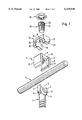
- FIG. 1 shows an exploded view of the pedicle screw, the rod and the fixing device of this invention.
- FIG. 2 shows, in the rod direction, a view of the pedicle screw and of the fixing device held in an instrument.
- FIG. 3 shows a side view, corresponding to FIG. 2, and from the opposite direction, after connection to the pedicle screw.
- FIG. 4 shows a cross-sectional view of the instrument.
- FIG. 5 shows a side view of the fixing device.
- FIG. 6 shows a side view of the fixing device rotated 90 degrees relative to the view in FIG. 5.
- FIG. 7 shows a cross-section through the instrument with the fixing device held therein and the screwdriver.
- FIG. 8 shows the pedicle screw with a rod fitted in its receiving seat, before the fixing device is applied.
- FIG. 9 shows the pedicle screw, rod, fixing device, instrument, and screw driver in the assembled state.
- FIG. 10 shows the pedicle screw, the rod and the fixing device in the final mounted state.
- the pedicle screw 1 has a head 2 which is formed by two fork legs 3 which are shaped as a U and between which the receiving seat 4 for the rod 5 is situated. Near the ends of the legs 3 towards the shank there are grooves 6 which run perpendicular to the direction of the screw shank and parallel to the rod direction set by the receiving seat 4. The outer surfaces of the legs 3 are parallel to each other and to the plane defined by the longitudinal direction of the screw and the direction of the rod.
- the clamping yoke 7, of a U shape consists of two plate-like, mutually parallel legs 8 and of a bridge 9.
- the inside diameter between the legs 8 is equal to the width of the screw head between the outer surfaces of the legs 3.
- the legs 8 are bent towards one another and in this area carry a rib 10 on each inner side, which rib 10 is designed matching the grooves 6 of the pedicle screw.
- the screw head can therefore be fitted into the space formed between the legs 8 and the bridge 9 of the fixing yoke, as is depicted in FIG. 3. It will be observed that the flanks of the ribs 10 and of the grooves 6 are inclined in such a way that they hold the two parts together with positive fit when they are being pulled apart by forces directed in the direction of the arrow 11 (FIG. 2).
- the bridge 9 of the clamping yoke 7 has at its center a threaded bore 12 in which a fixing screw 13 fits.
- the latter serves to clamp the fixing yoke 14 onto the clamping yoke 7.
- the fixing yoke 14 consists of a bridge 15 and two legs 16, 17, whose width corresponds, with slight play, to the inside diameter between the legs 8 of the clamping yoke 7.
- the end faces 18 of the bridge 9 of the clamping yoke 7 are set back a little in relation to the edges of the legs 8.
- the inside diameter between the legs 16, 17 of the fixing clamp 14 is smaller than the width of the legs 8 and greater than that of the bridge 9 of the clamping yoke 7.
- the bridge 15 of the fixing yoke includes at its center a through-bore 19 for the fixing screw 13, whose head 20 sits on the upper side of the bridge 15 or in a corresponding depression therein when the parts are drawn together.
- the head 20 of the fixing screw 13 is provided with an external thread 21 matching a locking nut 22 which serves to secure the fixing screw in the mounted state.
- the fixing screw 13 includes in the head 20 a hexagonal recess for the engagement of a screwdriver 23.
- FIG. 10 When the parts shown in FIG. 2 have been assembled completely, the configuration shown in FIG. 10 is obtained.
- the rod 5 lies in the receiving seat 4 of the pedicle screw.
- the clamping yoke 7, of which only a part of the bridge 9 is visible in FIG. 10, is pushed over the head of the pedicle screw and is connected to the latter with positive fit via the ribs 10 and grooves 6.
- the fixing yoke 14 is braced by means of the fixing screw 13 in such a way that the ends of its legs 16, 17 sit on the rod 5. It is thus secured and is aligned at right angles to the pedicle screw 1.
- the end of the fixing screw 13 can sit on the rod 5 in addition to the ends of the legs 16, 17 of the fixing clamp; however, this is not normally desired.
- the fixing screw 13 is secured in its position by the locking nut 22.
- the fixing device consisting of the yokes 7, 14, the screw 13 and locking nut 22 must be pushed over the head of the pedicle screw 1 after the rod 5 has assumed its position in the receiving seat 4.
- the mounting 32 has an inside diameter which is equal, with play, to the width of the bridge 15 of the fixing yoke 14 and has at the lower end two ribs 33 which face one another and via which it is pushed under the edges of the bridge 15 of the fixing plate.
- the leg 16 adjoining the bridge 15 has cutouts 34 which correspond to the cross-sectional size of the ribs 33.
- the leg 17 does not have any cutouts of this kind.
- Instrument and fixing device then together form an easy to handle unit, where the fixing device can be easily located in relation to the head 2 of the pedicle screw 1, onto which it is to be applied, by means of the instrument. Nor is there any difficulty in exerting pressure on the rod, by way of the instrument and via the fixing device, if the rod resists insertion into the receiving seat 4 of the pedicle screw.
- the fixing device can be placed on the head 2 of the pedicle screw although the legs 3 of the pedicle screw extend over the entire inner height of the clamping yoke 7, the leg 17 of the fixing yoke has cutouts 35.
- the other leg 16 does not have any cutouts of this kind.
- the fixing device can therefore be placed on the pedicle screw only from one side and in one direction.
- the purpose of this arrangement is that a limit stop is formed by the leg 16 in cooperation with the screw head 2, by means of which limit stop the correct final position of the fixing device in relation to the screw head is determined.
- FIG. 3 The bridges 15 and 9 of the fixing yoke and clamping yoke 14 and 7, respectively, are drawn together by means of the screw 13 in such a way that the ribs 33 of the instrument 30 are clamped between the underside of the edges of the bridge 15 and the upper side of the bridge 9.
- This method of securing has the advantage that all the parts of the fixing device are connected rigidly to the instrument and the physician therefore has a very reliable sense of the position of the fixing device during fitting.
- a precondition for this is that in the state shown in FIG.
- FIG. 2 The other possibility for locking the fixing device on the instrument 30 is demonstrated in FIG. 2.
- the instrument is connected to the fixing device in such a way that the ribs 33 lie under the edges of the bridge 15 of the fixing yoke 14.
- the removal of the fixing device from this position is prevented by the fact that the screwdriver 23, which is guided through a bore of the grip 31 of the instrument 30, engages in the hexagonal depression of the screw head 21.
- This locking position of the screwdriver 23 can be maintained either by means of the fact that the grips of the screwdriver and of the instrument are held together, and thus a corresponding force is exerted on the screwdriver, or a spring arrangement is provided between these parts, pressing the screwdriver 23 downwards in FIG. 2.
- This manner of securing the fixing device on the instrument dispenses with clamping the ribs 33 of the instrument between the two yokes, and the distance between the bridges 9 and 15 of the yokes can therefore be dimensioned so large that the ribs 33 are not even clamped when the fixing yoke 14 is braced against the rod 5.
- This procedure can therefore be effected while the instrument 30 is still connected to the fixing device.
- This not only has the advantage that a work stage is omitted, but also makes it easier to find the fixing screw 13 with the screwdriver 23 in the sometimes unclear operating field. This is because the screwdriver is by necessity guided through the bore in the instrument 30 to the screw head 21 and then finds itself in constant engagement therewith.
Abstract
Fixator for vertebra or bone fragments, with a rod and at least one pedicle screw which is to be secured thereon. The U-shaped head of the pedicle screw forms a receiving seat for the rod, which receives a fixing device for fixing the rod. The fixing device comprises a U-shaped clamping yoke whose legs can be connected with positive fit to the head of the pedicle screw and whose bridge holds a fixing screw. By means of the fixing screw, a U-shaped fixing yoke can be clamped with the ends of its legs against the rod, to the sides of the clamping yoke.
Description
The invention relates to a fixator for vertebrae or bone fragments, comprising a rod on which at least one pedicle screw is to be secured. The U-shaped head of the pedicle screw forms a receiving seat for the rod. The rod is held in the receiving seat by a fixing device which comprises a U-shaped clamping yoke whose legs can be connected with positive fit to the head of the pedicle screw and whose bridge holds a fixing screw. In a known spinal column fixator (DE-C 41 07 480) the fixing screw acts directly on the rod lying in the receiving seat. This has the disadvantage that the alternating forces which occur between rod and pedicle screw also act on the screw and may loosen it. This is particularly the case when the direction of the rod does not run exactly perpendicular to the longitudinal direction of the screw, and, as a result, a state of considerable looseness can arise upon relative movements, even when the screw has not moved.
The invention is therefore based on the object of making available a fixator of the type mentioned at the outset, which affords more secure connection between rod and pedicle screw and better mutual alignment to the perpendicular setting.
The solution according to the invention lies in the fact that the fixing screw does not act directly, or not exclusively directly, on the rod, and is instead used to clamp a U-shaped fixing yoke against the rod, with the ends of its legs to the sides of the clamping yoke.
The ends of the legs of the fixing yoke sit on the rod at a specific distance from the center of the fixing device and thus make it possible to exert a substantial restoring moment on this rod if it does not lie perpendicular in relation to the pedicle screw at the start of the fixing procedure. The perpendicular setting is therefore obtained very reliably during the course of the fixing procedure. This setting is also maintained very reliably under alternating forces. Relative movements between rod and fixing screw and within the fixing device do not in practice occur. Thus, the fixing screw is not acted upon by forces from alternating directions which may lead to its loosening. Rather, it is almost exclusively axial forces that act on the fixing screw.
Although the risk of loosening of the fixing screw is therefore considerably less than in the known solution, it can, in an advantageous embodiment of the invention, be provided with a securing device, in particular a locking nut. However, other known securing devices for these purposes can also be used.
In the known arrangement described at the outset, the interacting means on the head of the pedicle screw and on the clamping yoke, providing the positive fit, are designed as mutually engaging ribs and grooves running perpendicular to the direction of the pedicle screw and parallel to the rod. When, during the operation, the head of the pedicle screw is to be connected to the rod, it is often the case that these parts do not at the outset have the setting which they are intended to have; they first have to be adjusted in relation to each other by applying a certain force. Under these circumstances it can be difficult to align the fixing device with sufficient precision so that it can be pushed onto the head of the pedicle screw. The invention makes this procedure easier by making available an instrument for holding the fixing device in the correct direction. The instrument, which is equipped with a large hand grip, can be aligned easily in the desired manner, as a result of which the correct alignment of the fixing device is then also ensured. So that the fixing device is correctly aligned in relation to the instrument, according to the invention the instrument has a saddle-shaped holder part which has two rib-shaped projections which are located opposite one another and which engage under the edges of the bridge of the fixing yoke. The edges of the fixing yoke are in this way aligned with the direction of the ribs and thus also the direction of the instrument.
To ensure that the fixing device cannot be detached unintentionally from the instrument, the arrangement is set up in such a way that the rib-shaped projections of the instrument are clamped between the edges of the fixing yoke and the facing surface of the clamping yoke, by means of the fixing screw being tightened after insertion of the fixing device. The distance between the clamping yoke and the fixing yoke, as defined by the rib-shaped projections, should in this case be greater than the distance between these parts in the fixing state. The fixing yoke is thus still slightly raised in relation to the rod, and there is sufficient play present to push the fixing device onto the head of the pedicle screw, even when the rod is already located in the receiving seat of the pedicle screw. This arrangement, in which the fixing device is secured tightly on the instrument, by means of the ribs of the instrument being clamped between fixing yoke and clamping yoke, has the advantage that the fixing device sits on the instrument without any shaking. This facilitates application to the head of the pedicle screw. It requires, however, that the instrument be removed before the fixing device is tightened on the pedicle head, because the fixing state cannot be obtained as long as the fixing device is located on the instrument. In many cases this is not a problem, because the most difficult part of the manipulation is pushing the fixing device onto the head of the pedicle screw, and the subsequent tightening does not offer any particular problems.
The method can be simplified, however, if the mounting of the fixing device on the instrument is designed such that the fixing device can be tightened on the pedicle screw while it is still held in the instrument. For this purpose, the distance existing in the fixing state between the bridges of the fixing yoke and of the clamping yoke is of greater dimension than the height of the ribs holding the fixing device on the instrument. The instrument can therefore be detached from the fixing device even when the latter is clamped tight on the pedicle screw. This takes into consideration the fact that the fixing device cannot be braced on the instrument by drawing together the two yokes. However, fixing on the instrument can be achieved by means of the fact that the instrument and a screwdriver for manoeuvring the fixing screw are connected in such a way that the screwdriver applied to the screw head at the same time forms an obstacle to the withdrawal of the fixing device from the instrument.
In any event, it has proven expedient for the instrument to have a grip shaft which is designed as a guide for a screwdriver cooperating with the fixing screw. The simple insertion of the screwdriver into the guide ensures that the screwdriver readily finds the position in which it engages in the fixing screw. In this position, it locks the fixing device securely against a movement whose direction runs transverse to the direction of the screwdriver and thus secures it on the instrument.
It is not only pushing the fixing device onto the head of the pedicle screw that can prove difficult under operating conditions, but also subsequently finding the correct centring position of the fixing device relative to the pedicle screw. According to the invention, this can be made easier by the fact that the head of the pedicle screw and the fixing device have an interacting pair of limit stops delimiting the position of the fixing device in the correct position relative to the head of the pedicle screw in one direction. When the fixing device is pushed onto the screw head, the correct position thus results automatically.
The same principle can be used to facilitate the insertion of the fixing device into the instrument.
The invention is discussed in greater detail hereinbelow with reference to the drawings in which:
FIG. 1 shows an exploded view of the pedicle screw, the rod and the fixing device of this invention.
FIG. 2 shows, in the rod direction, a view of the pedicle screw and of the fixing device held in an instrument.
FIG. 3 shows a side view, corresponding to FIG. 2, and from the opposite direction, after connection to the pedicle screw.
FIG. 4 shows a cross-sectional view of the instrument.
FIG. 5 shows a side view of the fixing device.
FIG. 6 shows a side view of the fixing device rotated 90 degrees relative to the view in FIG. 5.
FIG. 7 shows a cross-section through the instrument with the fixing device held therein and the screwdriver.
FIG. 8 shows the pedicle screw with a rod fitted in its receiving seat, before the fixing device is applied.
FIG. 9 shows the pedicle screw, rod, fixing device, instrument, and screw driver in the assembled state.
FIG. 10 shows the pedicle screw, the rod and the fixing device in the final mounted state.
The pedicle screw 1 has a head 2 which is formed by two fork legs 3 which are shaped as a U and between which the receiving seat 4 for the rod 5 is situated. Near the ends of the legs 3 towards the shank there are grooves 6 which run perpendicular to the direction of the screw shank and parallel to the rod direction set by the receiving seat 4. The outer surfaces of the legs 3 are parallel to each other and to the plane defined by the longitudinal direction of the screw and the direction of the rod.
The clamping yoke 7, of a U shape, consists of two plate-like, mutually parallel legs 8 and of a bridge 9. The inside diameter between the legs 8 is equal to the width of the screw head between the outer surfaces of the legs 3. At their ends near the opening, the legs 8 are bent towards one another and in this area carry a rib 10 on each inner side, which rib 10 is designed matching the grooves 6 of the pedicle screw. The screw head can therefore be fitted into the space formed between the legs 8 and the bridge 9 of the fixing yoke, as is depicted in FIG. 3. It will be observed that the flanks of the ribs 10 and of the grooves 6 are inclined in such a way that they hold the two parts together with positive fit when they are being pulled apart by forces directed in the direction of the arrow 11 (FIG. 2).
The bridge 9 of the clamping yoke 7 has at its center a threaded bore 12 in which a fixing screw 13 fits. The latter serves to clamp the fixing yoke 14 onto the clamping yoke 7. The fixing yoke 14 consists of a bridge 15 and two legs 16, 17, whose width corresponds, with slight play, to the inside diameter between the legs 8 of the clamping yoke 7. The end faces 18 of the bridge 9 of the clamping yoke 7 are set back a little in relation to the edges of the legs 8. The inside diameter between the legs 16, 17 of the fixing clamp 14 is smaller than the width of the legs 8 and greater than that of the bridge 9 of the clamping yoke 7. When the fixing clamp 14 is placed on the clamping yoke 7, the legs 16, 17 of the fixing yoke are therefore guided between the legs 8 of the clamping yoke. The bridge 15 of the fixing yoke includes at its center a through-bore 19 for the fixing screw 13, whose head 20 sits on the upper side of the bridge 15 or in a corresponding depression therein when the parts are drawn together. The head 20 of the fixing screw 13 is provided with an external thread 21 matching a locking nut 22 which serves to secure the fixing screw in the mounted state. The fixing screw 13 includes in the head 20 a hexagonal recess for the engagement of a screwdriver 23.
When the parts shown in FIG. 2 have been assembled completely, the configuration shown in FIG. 10 is obtained. The rod 5 lies in the receiving seat 4 of the pedicle screw. The clamping yoke 7, of which only a part of the bridge 9 is visible in FIG. 10, is pushed over the head of the pedicle screw and is connected to the latter with positive fit via the ribs 10 and grooves 6. The fixing yoke 14 is braced by means of the fixing screw 13 in such a way that the ends of its legs 16, 17 sit on the rod 5. It is thus secured and is aligned at right angles to the pedicle screw 1. The end of the fixing screw 13 can sit on the rod 5 in addition to the ends of the legs 16, 17 of the fixing clamp; however, this is not normally desired. The fixing screw 13 is secured in its position by the locking nut 22.
In order to obtain this arrangement, the fixing device consisting of the yokes 7, 14, the screw 13 and locking nut 22 must be pushed over the head of the pedicle screw 1 after the rod 5 has assumed its position in the receiving seat 4. This is done by means of the instrument 30 which has a sturdy and easy to handle grip rod 31 and, at the end thereof, forms a saddle-shaped or fork-shaped mounting 32 for the fixing device. The mounting 32 has an inside diameter which is equal, with play, to the width of the bridge 15 of the fixing yoke 14 and has at the lower end two ribs 33 which face one another and via which it is pushed under the edges of the bridge 15 of the fixing plate. To make this possible, the leg 16 adjoining the bridge 15 has cutouts 34 which correspond to the cross-sectional size of the ribs 33. The leg 17 does not have any cutouts of this kind. When the instrument is pushed with its mounting 32 onto the bridge 15 of the fixing yoke, its end position is therefore determined by the ends of the ribs 33 abutting on the leg 17. These parts form a limit stop which determines the secure positioning of the fixing device in the mounting 32 of the instrument 30. In this position, the fixing device can be locked on the instrument in a manner described in detail hereinbelow.
Instrument and fixing device then together form an easy to handle unit, where the fixing device can be easily located in relation to the head 2 of the pedicle screw 1, onto which it is to be applied, by means of the instrument. Nor is there any difficulty in exerting pressure on the rod, by way of the instrument and via the fixing device, if the rod resists insertion into the receiving seat 4 of the pedicle screw.
So that the fixing device can be placed on the head 2 of the pedicle screw although the legs 3 of the pedicle screw extend over the entire inner height of the clamping yoke 7, the leg 17 of the fixing yoke has cutouts 35. The other leg 16 does not have any cutouts of this kind. The fixing device can therefore be placed on the pedicle screw only from one side and in one direction. The purpose of this arrangement is that a limit stop is formed by the leg 16 in cooperation with the screw head 2, by means of which limit stop the correct final position of the fixing device in relation to the screw head is determined.
When the fixing device has reached this position, the fixing screw 13 and the locking nut 22 are tightened.
There are two possible ways of holding the fixing device securely on the instrument 30 during assembly. The first of these possibilities is demonstrated in FIG. 3. The bridges 15 and 9 of the fixing yoke and clamping yoke 14 and 7, respectively, are drawn together by means of the screw 13 in such a way that the ribs 33 of the instrument 30 are clamped between the underside of the edges of the bridge 15 and the upper side of the bridge 9. This method of securing has the advantage that all the parts of the fixing device are connected rigidly to the instrument and the physician therefore has a very reliable sense of the position of the fixing device during fitting. A precondition for this is that in the state shown in FIG. 3, that is to say when the ribs 33 are clamped between the yokes, there is still sufficient play present below the ends of the legs 16, 17 in relation to the rod 5. Otherwise, the fixing device would not be able to be pushed onto the pedicle screw and the rod 5 situated in it. This has the disadvantage that the clamping yoke 14 cannot be braced against the rod 5 as long as the instrument 30 is connected to the fixing device. Instead, the latter first has to be removed before the fixing screw 13 is tightened.
The other possibility for locking the fixing device on the instrument 30 is demonstrated in FIG. 2. As has been described before, the instrument is connected to the fixing device in such a way that the ribs 33 lie under the edges of the bridge 15 of the fixing yoke 14. The removal of the fixing device from this position is prevented by the fact that the screwdriver 23, which is guided through a bore of the grip 31 of the instrument 30, engages in the hexagonal depression of the screw head 21. This locking position of the screwdriver 23 can be maintained either by means of the fact that the grips of the screwdriver and of the instrument are held together, and thus a corresponding force is exerted on the screwdriver, or a spring arrangement is provided between these parts, pressing the screwdriver 23 downwards in FIG. 2. This manner of securing the fixing device on the instrument dispenses with clamping the ribs 33 of the instrument between the two yokes, and the distance between the bridges 9 and 15 of the yokes can therefore be dimensioned so large that the ribs 33 are not even clamped when the fixing yoke 14 is braced against the rod 5. This procedure can therefore be effected while the instrument 30 is still connected to the fixing device. This not only has the advantage that a work stage is omitted, but also makes it easier to find the fixing screw 13 with the screwdriver 23 in the sometimes unclear operating field. This is because the screwdriver is by necessity guided through the bore in the instrument 30 to the screw head 21 and then finds itself in constant engagement therewith.
Claims (12)
1. A fixator for vertebra or bone fragments, comprising:
(a) a rod;
(b) at least one pedicle screw having a U-shaped head formed as a receiving seat for the rod; and
(c) a fixing device for fixing the rod in the receiving seat, comprising:
(i) a U-shaped clamping yoke having legs that can be connected to sides of the U-shaped head of the pedicle screw to provide a positive fit between said legs and said sides;
(ii) a U-shaped fixing yoke; and
(iii) a fixing screw that serves to connect a bridge of the fixing yoke to a bridge of the clamping yoke.
2. A fixator for vertebra or bone fragments according to claim 1, further comprising a securing device for the fixing screw.
3. A fixator for vertebra or bone fragments according to claim 2, wherein the securing device is a locking nut.
4. A fixator for vertebra or bone fragments according to claim 1, comprising complementary ribs and grooves on the legs of the clamping yoke and the sides of the pedicle screw such that the clamping yoke can be pushed, relative to the longitudinal direction of the complementary ribs and grooves, onto the head of the pedicle screw.
5. A fixator for vertebra or bone fragments according to claim 4, wherein one or both of the legs of the fixing yoke has a cutout on each side of the leg adjoining the bridge of the fixing yoke.
6. A fixator for vertebra or bone fragments according to claim 5, further comprising an instrument for holding the fixing device, said instrument comprising a mounting at the end of the instrument having legs each with a rib-like projection that engages under edges of the bridge of the fixing yoke through the cutouts.
7. A fixator for vertebra or bone fragments according to claim 6, wherein
(a) the rib-like projections of the instrument are clamped between the bridge of the fixing yoke and the bridge of the clamping yoke by means of the fixing screw; and
(b) a distance between the bridge of the fixing yoke and the bridge of the clamping yoke when the rod is fixed in the receiving seat is less than the height of the rib-like projections.
8. A fixator for vertebra or bone fragments according to claim 6, wherein a distance between the bridge of the fixing yoke and the bridge of the clamping yoke when the rod is fixed in the receiving seat is greater than the height of the rib-like projections.
9. A fixator for vertebra or bone fragments according to claim 6, wherein the instrument has a grip shaft designed such that it serves as a guide for a screwdriver cooperating with the fixing screw.
10. A fixator for vertebra or bone fragments according to claim 9, wherein the grip shaft is hollow along its length creating a bore through which the screwdriver is guided.
11. A fixator for vertebra or bone fragments according to claim 4, wherein the fixing device and the head of the pedicle screw have an interacting pair of limit stops that delimit the position of the fixing device relative to the head of the pedicle screw in one direction.
12. A fixator for vertebra or bone fragments according to claim 6, wherein the fixing device and the mounting at the end of the instrument have an interacting pair of limit stops that delimit the position of the instrument relative to the fixing device in one direction.
Applications Claiming Priority (3)
| Application Number | Priority Date | Filing Date | Title |
|---|---|---|---|
| DE29606468U DE29606468U1 (en) | 1996-04-09 | 1996-04-09 | Spinal fixator |
| DE29606468U | 1996-04-09 | ||
| PCT/EP1997/000900 WO1997037604A1 (en) | 1996-04-09 | 1997-02-25 | Spinal fixing device |
Publications (1)
| Publication Number | Publication Date |
|---|---|
| US6139549A true US6139549A (en) | 2000-10-31 |
Family
ID=8022339
Family Applications (1)
| Application Number | Title | Priority Date | Filing Date |
|---|---|---|---|
| US09/254,290 Expired - Lifetime US6139549A (en) | 1996-04-09 | 1997-02-25 | Spinal fixing device |
Country Status (9)
| Country | Link |
|---|---|
| US (1) | US6139549A (en) |
| EP (1) | EP0892623B1 (en) |
| JP (1) | JP3605647B2 (en) |
| KR (1) | KR100369424B1 (en) |
| BR (1) | BR9708628A (en) |
| DE (2) | DE29606468U1 (en) |
| ES (1) | ES2176683T3 (en) |
| TW (1) | TW335348B (en) |
| WO (1) | WO1997037604A1 (en) |
Cited By (195)
| Publication number | Priority date | Publication date | Assignee | Title |
|---|---|---|---|---|
| US6251112B1 (en) * | 2000-04-18 | 2001-06-26 | Roger P. Jackson | Thin profile closure cap for open ended medical implant |
| US6258090B1 (en) * | 2000-04-28 | 2001-07-10 | Roger P. Jackson | Closure for open ended medical implant and removal tool |
| US20020035366A1 (en) * | 2000-09-18 | 2002-03-21 | Reto Walder | Pedicle screw for intervertebral support elements |
| US6402752B2 (en) * | 2000-02-07 | 2002-06-11 | Ulrich Gmbh & Co. Kg | Polyaxial pedicle-screw |
| US20020120272A1 (en) * | 1998-06-17 | 2002-08-29 | Hansen Yuan | Device for securing spinal rods |
| US20020161368A1 (en) * | 1999-10-20 | 2002-10-31 | Foley Kevin T. | Instruments and methods for stabilization of bony structures |
| US20030028192A1 (en) * | 2000-01-13 | 2003-02-06 | Manuel Schar | Device for releasably clamping a longitudinal member within a surgical implant |
| US20030109880A1 (en) * | 2001-08-01 | 2003-06-12 | Showa Ika Kohgyo Co., Ltd. | Bone connector |
| US20030187434A1 (en) * | 2002-01-24 | 2003-10-02 | A-Spine Inc. | Rotary device for fixing spinal column under treatment |
| US20030208204A1 (en) * | 2001-04-17 | 2003-11-06 | Bailey Kirk J. | Anterior cervical plating system |
| US6656190B2 (en) * | 2000-03-15 | 2003-12-02 | Spinevision S. A. | Implant prehension device |
| US20030225408A1 (en) * | 2002-06-04 | 2003-12-04 | Howmedica Osteonics Corp. | Apparatus for securing a spinal rod system |
| US6660006B2 (en) | 2002-04-17 | 2003-12-09 | Stryker Spine | Rod persuader |
| WO2004032726A2 (en) * | 2002-10-11 | 2004-04-22 | Abdou M Samy | Distraction screw for skeletal surgery and method of use |
| US20040092938A1 (en) * | 2002-11-08 | 2004-05-13 | Scient ' X | Clamping nut for an osteosynthesis device |
| US20040102781A1 (en) * | 2002-11-25 | 2004-05-27 | U & I Corporation | Bone fixation apparatus, method and tool for assembling the same |
| US6743231B1 (en) * | 2000-10-02 | 2004-06-01 | Sulzer Spine-Tech Inc. | Temporary spinal fixation apparatuses and methods |
| US20040138662A1 (en) * | 2002-10-30 | 2004-07-15 | Landry Michael E. | Spinal stabilization systems and methods |
| US20040147936A1 (en) * | 2003-01-28 | 2004-07-29 | Rosenberg William S. | Spinal rod approximator |
| US20040158247A1 (en) * | 2003-02-07 | 2004-08-12 | Arthit Sitiso | Polyaxial pedicle screw system |
| US20050096659A1 (en) * | 2003-10-31 | 2005-05-05 | Stefan Freudiger | Pedicle screw with a closure device for the fixing of elastic rod elements |
| FR2862863A1 (en) * | 2003-12-02 | 2005-06-03 | Eurosurgical | CLIPSEUSE-TYPE SURGICAL INSTRUMENT FOR SPINAL IMPLANT |
| WO2005055843A1 (en) | 2003-12-02 | 2005-06-23 | Eurosurgical | Clipping-type surgical instrument for spinal implant |
| US20050149053A1 (en) * | 2003-12-17 | 2005-07-07 | Varieur Michael S. | Instruments and methods for bone anchor engagement and spinal rod reduction |
| US20050149048A1 (en) * | 2003-12-23 | 2005-07-07 | Eurosurgical Sa | Surgical instrument of the releaser type for a spinal implant |
| US20050177163A1 (en) * | 2003-12-29 | 2005-08-11 | Abdou M. S. | Plating system for bone fixation and method of implantation |
| US20050188469A1 (en) * | 2004-02-27 | 2005-09-01 | Custom Spine, Inc. | Screwdriver |
| US20050203530A1 (en) * | 2000-03-28 | 2005-09-15 | Showa Ika Kohgyo Co., Ltd. | Spinal implant, driver tool and nut guide |
| US20050228400A1 (en) * | 2004-03-31 | 2005-10-13 | Chao Nam T | Instrument for inserting, adjusting and removing pedicle screws and other orthopedic implants |
| US20050228392A1 (en) * | 2004-04-12 | 2005-10-13 | Keyer Thomas R | Rod persuader |
| US20050277931A1 (en) * | 2004-06-09 | 2005-12-15 | Spinal Generations, Llc | Spinal fixation system |
| US20050288669A1 (en) * | 2004-06-14 | 2005-12-29 | Abdou M S | Occipito fixation system and method of use |
| US20060009775A1 (en) * | 2004-07-06 | 2006-01-12 | Brian Dec | Spinal rod insertion instrument |
| US20060036252A1 (en) * | 2004-08-12 | 2006-02-16 | Baynham Bret O | Polyaxial screw |
| US20060069391A1 (en) * | 2004-02-27 | 2006-03-30 | Jackson Roger P | Spinal fixation tool attachment structure |
| US20060074445A1 (en) * | 2004-09-29 | 2006-04-06 | David Gerber | Less invasive surgical system and methods |
| US20060095035A1 (en) * | 2004-11-03 | 2006-05-04 | Jones Robert J | Instruments and methods for reduction of vertebral bodies |
| US20060106380A1 (en) * | 2003-10-21 | 2006-05-18 | Innovative Spinal Technologies | Extension for use with stabilization systems for internal structures |
| US20060111713A1 (en) * | 2004-11-23 | 2006-05-25 | Jackson Roger P | Spinal fixation tool set and method |
| US20060184178A1 (en) * | 2004-02-27 | 2006-08-17 | Jackson Roger P | Orthopedic implant rod reduction tool set and method |
| US20060229615A1 (en) * | 2005-02-18 | 2006-10-12 | Abdou M S | Devices and methods for dynamic fixation of skeletal structure |
| US20060235393A1 (en) * | 2000-09-22 | 2006-10-19 | Depuy Spine, Inc. | Locking cap assembly for spinal fixation instrumentation |
| US20060254784A1 (en) * | 2003-09-08 | 2006-11-16 | Stephan Hartmann | Longitudinal support |
| US20060264252A1 (en) * | 2005-05-23 | 2006-11-23 | White Gehrig H | System and method for providing a host console for use with an electronic card game |
| US20070016189A1 (en) * | 2005-06-30 | 2007-01-18 | Depuy Spine Sarl | Orthopedic clamping hook assembly |
| US20070043361A1 (en) * | 2005-02-17 | 2007-02-22 | Malandain Hugues F | Percutaneous spinal implants and methods |
| US20070049931A1 (en) * | 2005-08-26 | 2007-03-01 | Sdgi Holdings, Inc. | Instruments for minimally invasive stabilization of bony structures |
| US20070055242A1 (en) * | 2005-07-27 | 2007-03-08 | Bailly Frank E | Device for securing spinal rods |
| US20070055239A1 (en) * | 2004-06-09 | 2007-03-08 | Spinal Generations, Llc | Spinal fixation system |
| US20070093824A1 (en) * | 2005-09-22 | 2007-04-26 | Hestad Hugh D | Pedicle fixation rod alignment system |
| US20070106383A1 (en) * | 2005-10-03 | 2007-05-10 | Abdou M S | Devices and methods for inter-vertebral orthopedic device placement |
| US20070162010A1 (en) * | 2005-03-04 | 2007-07-12 | Chao Nam T | Instruments and methods for manipulating vertebra |
| US20070161998A1 (en) * | 2005-10-28 | 2007-07-12 | Dale Whipple | Instruments and Methods For Manipulating A Spinal Rod |
| US20070161989A1 (en) * | 2005-12-20 | 2007-07-12 | Sdgi Holdings, Inc. | Vertebral implant inserter and method of use |
| US20070167954A1 (en) * | 2003-12-16 | 2007-07-19 | Christopher Sicvol | Percutaneous Access Devices And Bone Anchor Assemblies |
| US20070260261A1 (en) * | 2005-06-02 | 2007-11-08 | Depuy Spine, Inc. | Instruments and methods for manipulating a spinal fixation element |
| US20070288002A1 (en) * | 2006-05-30 | 2007-12-13 | Carls Thomas A | Locking device and method employing a posted member to control positioning of a stabilization member of a bone stabilization system |
| US20080015580A1 (en) * | 2006-04-28 | 2008-01-17 | Nam Chao | Large diameter bone anchor assembly |
| US20080015601A1 (en) * | 2006-06-14 | 2008-01-17 | Michael Castro | Reduction device and method of use |
| US20080039946A1 (en) * | 1997-01-02 | 2008-02-14 | Zucherman James F | Spine distraction implant and method |
| US20080058810A1 (en) * | 2003-01-10 | 2008-03-06 | Abdou M S | Bone screw systems and methods of use |
| US20080140086A1 (en) * | 2006-12-07 | 2008-06-12 | Jesse Gabriel Moore | Gravity feed implant dispenser |
| US20080161823A1 (en) * | 2006-09-29 | 2008-07-03 | Depuy Products, Inc. | Instrument for modular orthopaedic prosthesis |
| US20080183214A1 (en) * | 2004-09-08 | 2008-07-31 | Matthew Copp | System and Methods For Performing Spinal Fixation |
| US20080243190A1 (en) * | 2007-03-29 | 2008-10-02 | Depuy Spine, Inc. | In-line rod reduction device and methods |
| US20080249531A1 (en) * | 2007-02-27 | 2008-10-09 | Warsaw Orthopedic, Inc. | Instruments and methods for minimally invasive insertion of dynamic implants |
| US20080262551A1 (en) * | 2007-04-19 | 2008-10-23 | Zimmer Spine, Inc. | Method and associated instrumentation for installation of spinal dynamic stabilization system |
| US20080275456A1 (en) * | 2007-05-02 | 2008-11-06 | Zimmer Spine, Inc. | Installation systems for spinal stabilization system and related methods |
| US20090088764A1 (en) * | 2007-09-28 | 2009-04-02 | Depuy Spine, Inc. | Dual pivot instrument for reduction of a fixation element and method of use |
| EP2085040A1 (en) * | 2005-05-27 | 2009-08-05 | Biedermann Motech GmbH | Tool for holding or guiding a receiving part for connecting a shank of a bone anchoring element to a rod |
| US20090228054A1 (en) * | 2008-01-29 | 2009-09-10 | Jeffrey Hoffman | Rod Locking Instrument |
| US20090228053A1 (en) * | 2008-03-10 | 2009-09-10 | Eric Kolb | Derotation instrument with reduction functionality |
| US20090312804A1 (en) * | 2008-06-17 | 2009-12-17 | Thomas Gamache | Adjustable implant assembly |
| WO2010033445A2 (en) * | 2008-09-16 | 2010-03-25 | Spinefrontier, Inc. | Spinal screw assembly and screw insertion tool |
| US20100087874A1 (en) * | 2005-12-21 | 2010-04-08 | Jong Wuk Jang | Pedicle screw |
| US20100106196A1 (en) * | 2008-10-24 | 2010-04-29 | Paul Lawrence Erickson | Method and system for attaching a plate to a bone |
| US7722651B2 (en) | 2005-10-21 | 2010-05-25 | Depuy Spine, Inc. | Adjustable bone screw assembly |
| US7758584B2 (en) | 2006-04-11 | 2010-07-20 | Synthes Usa, Llc | Minimally invasive fixation system |
| US7842044B2 (en) | 2003-12-17 | 2010-11-30 | Depuy Spine, Inc. | Instruments and methods for bone anchor engagement and spinal rod reduction |
| WO2011006268A1 (en) | 2009-07-16 | 2011-01-20 | Spinesave Ag | Spinal implant set including a quick closure |
| US7887539B2 (en) | 2003-01-24 | 2011-02-15 | Depuy Spine, Inc. | Spinal rod approximators |
| US7887541B2 (en) | 2007-07-26 | 2011-02-15 | Depuy Spine, Inc. | Spinal rod reduction instruments and methods for use |
| US7909830B2 (en) | 2005-08-25 | 2011-03-22 | Synthes Usa, Llc | Methods of spinal fixation and instrumentation |
| US7918857B2 (en) | 2006-09-26 | 2011-04-05 | Depuy Spine, Inc. | Minimally invasive bone anchor extensions |
| US20110087293A1 (en) * | 2009-10-14 | 2011-04-14 | Ebi, Llc | Deformable Device For Minimally Invasive Fixation |
| US7927354B2 (en) | 2005-02-17 | 2011-04-19 | Kyphon Sarl | Percutaneous spinal implants and methods |
| US7938848B2 (en) * | 2004-06-09 | 2011-05-10 | Life Spine, Inc. | Spinal fixation system |
| US7951172B2 (en) | 2005-03-04 | 2011-05-31 | Depuy Spine Sarl | Constrained motion bone screw assembly |
| US7955363B2 (en) | 2002-04-18 | 2011-06-07 | Aesculap Implant Systems, Llc | Screw and rod fixation assembly and device |
| US7955392B2 (en) | 2006-12-14 | 2011-06-07 | Warsaw Orthopedic, Inc. | Interspinous process devices and methods |
| US7967826B2 (en) | 2003-10-21 | 2011-06-28 | Theken Spine, Llc | Connector transfer tool for internal structure stabilization systems |
| US20110202096A1 (en) * | 2010-02-12 | 2011-08-18 | John White | Spinal Rod and Screw Securing Apparatus and Method |
| US8029567B2 (en) | 2005-02-17 | 2011-10-04 | Kyphon Sarl | Percutaneous spinal implants and methods |
| US8038699B2 (en) | 2006-09-26 | 2011-10-18 | Ebi, Llc | Percutaneous instrument assembly |
| US8066739B2 (en) | 2004-02-27 | 2011-11-29 | Jackson Roger P | Tool system for dynamic spinal implants |
| US20110313470A1 (en) * | 2010-06-18 | 2011-12-22 | Spine Wave, Inc. | Pedicle Screw Extension for Use in Percutaneous Spinal Fixation |
| US8092494B2 (en) | 2004-01-13 | 2012-01-10 | Life Spine, Inc. | Pedicle screw constructs for spine fixation systems |
| US8096995B2 (en) | 2005-02-17 | 2012-01-17 | Kyphon Sarl | Percutaneous spinal implants and methods |
| US8096994B2 (en) | 2005-02-17 | 2012-01-17 | Kyphon Sarl | Percutaneous spinal implants and methods |
| US8105368B2 (en) | 2005-09-30 | 2012-01-31 | Jackson Roger P | Dynamic stabilization connecting member with slitted core and outer sleeve |
| US8114131B2 (en) | 2008-11-05 | 2012-02-14 | Kyphon Sarl | Extension limiting devices and methods of use for the spine |
| US8152810B2 (en) | 2004-11-23 | 2012-04-10 | Jackson Roger P | Spinal fixation tool set and method |
| US8162952B2 (en) | 2006-09-26 | 2012-04-24 | Ebi, Llc | Percutaneous instrument assembly |
| US8167890B2 (en) | 2005-02-17 | 2012-05-01 | Kyphon Sarl | Percutaneous spinal implants and methods |
| US8172855B2 (en) | 2004-11-24 | 2012-05-08 | Abdou M S | Devices and methods for inter-vertebral orthopedic device placement |
| US8202304B2 (en) | 2002-08-21 | 2012-06-19 | Theken Spine, Llc | Methods and systems for performing spinal surgery |
| US8206394B2 (en) | 2009-05-13 | 2012-06-26 | Depuy Spine, Inc. | Torque limited instrument for manipulating a spinal rod relative to a bone anchor |
| US20120203281A1 (en) * | 2011-02-05 | 2012-08-09 | Alphatec Spine, Inc | Semi-rigid screw assembly |
| US8303630B2 (en) | 2006-07-27 | 2012-11-06 | Samy Abdou | Devices and methods for the minimally invasive treatment of spinal stenosis |
| US8308774B2 (en) | 2007-02-14 | 2012-11-13 | Pioneer Surgical Technology, Inc. | Spinal rod reducer and cap insertion apparatus |
| US8348952B2 (en) | 2006-01-26 | 2013-01-08 | Depuy International Ltd. | System and method for cooling a spinal correction device comprising a shape memory material for corrective spinal surgery |
| US8353932B2 (en) | 2005-09-30 | 2013-01-15 | Jackson Roger P | Polyaxial bone anchor assembly with one-piece closure, pressure insert and plastic elongate member |
| US8361123B2 (en) | 2009-10-16 | 2013-01-29 | Depuy Spine, Inc. | Bone anchor assemblies and methods of manufacturing and use thereof |
| US8366745B2 (en) | 2007-05-01 | 2013-02-05 | Jackson Roger P | Dynamic stabilization assembly having pre-compressed spacers with differential displacements |
| US8388659B1 (en) | 2008-10-17 | 2013-03-05 | Theken Spine, Llc | Spondylolisthesis screw and instrument for implantation |
| US8388660B1 (en) | 2006-08-01 | 2013-03-05 | Samy Abdou | Devices and methods for superior fixation of orthopedic devices onto the vertebral column |
| US8394133B2 (en) | 2004-02-27 | 2013-03-12 | Roger P. Jackson | Dynamic fixation assemblies with inner core and outer coil-like member |
| US8409208B2 (en) | 2008-10-04 | 2013-04-02 | M. Samy Abdou | Device and method to access the anterior column of the spine |
| US8414614B2 (en) | 2005-10-22 | 2013-04-09 | Depuy International Ltd | Implant kit for supporting a spinal column |
| US8414588B2 (en) | 2007-10-04 | 2013-04-09 | Depuy Spine, Inc. | Methods and devices for minimally invasive spinal connection element delivery |
| US8425563B2 (en) | 2006-01-13 | 2013-04-23 | Depuy International Ltd. | Spinal rod support kit |
| US8430914B2 (en) | 2007-10-24 | 2013-04-30 | Depuy Spine, Inc. | Assembly for orthopaedic surgery |
| US8439922B1 (en) | 2008-02-06 | 2013-05-14 | NiVasive, Inc. | Systems and methods for holding and implanting bone anchors |
| US8475498B2 (en) | 2007-01-18 | 2013-07-02 | Roger P. Jackson | Dynamic stabilization connecting member with cord connection |
| US8512383B2 (en) | 2010-06-18 | 2013-08-20 | Spine Wave, Inc. | Method of percutaneously fixing a connecting rod to a spine |
| US8535318B2 (en) | 2010-04-23 | 2013-09-17 | DePuy Synthes Products, LLC | Minimally invasive instrument set, devices and related methods |
| US8545538B2 (en) | 2005-12-19 | 2013-10-01 | M. Samy Abdou | Devices and methods for inter-vertebral orthopedic device placement |
| US8556938B2 (en) | 2009-06-15 | 2013-10-15 | Roger P. Jackson | Polyaxial bone anchor with non-pivotable retainer and pop-on shank, some with friction fit |
| US8591560B2 (en) | 2005-09-30 | 2013-11-26 | Roger P. Jackson | Dynamic stabilization connecting member with elastic core and outer sleeve |
| US8641734B2 (en) | 2009-02-13 | 2014-02-04 | DePuy Synthes Products, LLC | Dual spring posterior dynamic stabilization device with elongation limiting elastomers |
| US8663287B2 (en) | 2006-01-10 | 2014-03-04 | Life Spine, Inc. | Pedicle screw constructs and spinal rod attachment assemblies |
| US8679128B2 (en) | 2006-12-07 | 2014-03-25 | Zimmer Spine, Inc. | Apparatus and methods for reduction of vertebral bodies in a spine |
| US8709015B2 (en) | 2008-03-10 | 2014-04-29 | DePuy Synthes Products, LLC | Bilateral vertebral body derotation system |
| US20140257391A1 (en) * | 2004-04-20 | 2014-09-11 | James L. Chappuis | Internal Pedicle Insulator Apparatus and Method of Use |
| US8840617B2 (en) | 2010-02-26 | 2014-09-23 | Warsaw Orthopedic, Inc. | Interspinous process spacer diagnostic parallel balloon catheter and methods of use |
| US8845649B2 (en) | 2004-09-24 | 2014-09-30 | Roger P. Jackson | Spinal fixation tool set and method for rod reduction and fastener insertion |
| US8870920B2 (en) | 2005-10-07 | 2014-10-28 | M. Samy Abdou | Devices and methods for inter-vertebral orthopedic device placement |
| US8876874B2 (en) | 2006-08-21 | 2014-11-04 | M. Samy Abdou | Bone screw systems and methods of use |
| US8936626B1 (en) | 2012-02-17 | 2015-01-20 | Nuvasive, Inc. | Bi-cortical screw fixation |
| US8979904B2 (en) | 2007-05-01 | 2015-03-17 | Roger P Jackson | Connecting member with tensioned cord, low profile rigid sleeve and spacer with torsion control |
| US9005249B2 (en) | 2011-07-11 | 2015-04-14 | Life Spine, Inc. | Spinal rod connector assembly |
| US9050139B2 (en) | 2004-02-27 | 2015-06-09 | Roger P. Jackson | Orthopedic implant rod reduction tool set and method |
| US9198698B1 (en) | 2011-02-10 | 2015-12-01 | Nuvasive, Inc. | Minimally invasive spinal fixation system and related methods |
| US9216041B2 (en) | 2009-06-15 | 2015-12-22 | Roger P. Jackson | Spinal connecting members with tensioned cords and rigid sleeves for engaging compression inserts |
| US9216039B2 (en) | 2004-02-27 | 2015-12-22 | Roger P. Jackson | Dynamic spinal stabilization assemblies, tool set and method |
| US9232968B2 (en) | 2007-12-19 | 2016-01-12 | DePuy Synthes Products, Inc. | Polymeric pedicle rods and methods of manufacturing |
| US9277940B2 (en) | 2008-02-05 | 2016-03-08 | Zimmer Spine, Inc. | System and method for insertion of flexible spinal stabilization element |
| CN105434087A (en) * | 2016-01-13 | 2016-03-30 | 吴同申 | Dynamic pre-stressed clamping device for spine implant and mounting method thereof |
| US9308027B2 (en) | 2005-05-27 | 2016-04-12 | Roger P Jackson | Polyaxial bone screw with shank articulation pressure insert and method |
| US9314274B2 (en) | 2011-05-27 | 2016-04-19 | DePuy Synthes Products, Inc. | Minimally invasive spinal fixation system including vertebral alignment features |
| US9320543B2 (en) | 2009-06-25 | 2016-04-26 | DePuy Synthes Products, Inc. | Posterior dynamic stabilization device having a mobile anchor |
| US9439692B1 (en) * | 2015-10-09 | 2016-09-13 | Spine Wave, Inc. | Minimally invasive spinal fixation system and method therefor |
| US9445844B2 (en) | 2010-03-24 | 2016-09-20 | DePuy Synthes Products, Inc. | Composite material posterior dynamic stabilization spring rod |
| US9451993B2 (en) | 2014-01-09 | 2016-09-27 | Roger P. Jackson | Bi-radial pop-on cervical bone anchor |
| US9451989B2 (en) | 2007-01-18 | 2016-09-27 | Roger P Jackson | Dynamic stabilization members with elastic and inelastic sections |
| US9486256B1 (en) | 2013-03-15 | 2016-11-08 | Nuvasive, Inc. | Rod reduction assemblies and related methods |
| US9522021B2 (en) | 2004-11-23 | 2016-12-20 | Roger P. Jackson | Polyaxial bone anchor with retainer with notch for mono-axial motion |
| US9539012B2 (en) | 2002-10-30 | 2017-01-10 | Zimmer Spine, Inc. | Spinal stabilization systems with quick-connect sleeve assemblies for use in surgical procedures |
| US9566091B2 (en) | 2010-05-05 | 2017-02-14 | Biedermann Technologies Gmbh & Co. Kg | Method and tool for assembling a bone anchoring device |
| US9566092B2 (en) | 2013-10-29 | 2017-02-14 | Roger P. Jackson | Cervical bone anchor with collet retainer and outer locking sleeve |
| US9597119B2 (en) | 2014-06-04 | 2017-03-21 | Roger P. Jackson | Polyaxial bone anchor with polymer sleeve |
| US9636146B2 (en) | 2012-01-10 | 2017-05-02 | Roger P. Jackson | Multi-start closures for open implants |
| US9655653B2 (en) | 2013-03-22 | 2017-05-23 | Aesculap Ag | Vertebral column-stabilizing system and surgical fastening element for a vertebral column-stabilizing system |
| US9717533B2 (en) | 2013-12-12 | 2017-08-01 | Roger P. Jackson | Bone anchor closure pivot-splay control flange form guide and advancement structure |
| US9770265B2 (en) | 2012-11-21 | 2017-09-26 | Roger P. Jackson | Splay control closure for open bone anchor |
| US9808281B2 (en) | 2009-05-20 | 2017-11-07 | DePuy Synthes Products, Inc. | Patient-mounted retraction |
| US9867714B1 (en) | 2011-09-23 | 2018-01-16 | Samy Abdou | Spinal fixation devices and methods of use |
| US9962197B2 (en) | 2015-05-15 | 2018-05-08 | Biedermann Technologies Gmbh & Co. Kg | Instrument for use with a bone anchoring device in spinal surgery and system including the instrument and a bone anchoring device |
| US9974577B1 (en) | 2015-05-21 | 2018-05-22 | Nuvasive, Inc. | Methods and instruments for performing leveraged reduction during single position spine surgery |
| US10039578B2 (en) | 2003-12-16 | 2018-08-07 | DePuy Synthes Products, Inc. | Methods and devices for minimally invasive spinal fixation element placement |
| US10064658B2 (en) | 2014-06-04 | 2018-09-04 | Roger P. Jackson | Polyaxial bone anchor with insert guides |
| US10111757B2 (en) | 2012-10-22 | 2018-10-30 | Cogent Spine, LLC | Devices and methods for spinal stabilization and instrumentation |
| US20190046239A1 (en) * | 2016-04-27 | 2019-02-14 | Warsaw Orthopedic, Inc. | Spinal correction system and method |
| US10206723B2 (en) | 2013-03-14 | 2019-02-19 | Stryker European Holdings I, Llc | Rod inserter and insertion tube |
| US10258382B2 (en) | 2007-01-18 | 2019-04-16 | Roger P. Jackson | Rod-cord dynamic connection assemblies with slidable bone anchor attachment members along the cord |
| US10383660B2 (en) | 2007-05-01 | 2019-08-20 | Roger P. Jackson | Soft stabilization assemblies with pretensioned cords |
| US10398481B2 (en) | 2016-10-03 | 2019-09-03 | Nuvasive, Inc. | Spinal fixation system |
| US10543107B2 (en) | 2009-12-07 | 2020-01-28 | Samy Abdou | Devices and methods for minimally invasive spinal stabilization and instrumentation |
| US10548740B1 (en) | 2016-10-25 | 2020-02-04 | Samy Abdou | Devices and methods for vertebral bone realignment |
| US10695101B2 (en) | 2005-02-22 | 2020-06-30 | Roger P. Jackson | Bone anchor assembly with bottom loaded shank and insert engaging retainer |
| US10695105B2 (en) | 2012-08-28 | 2020-06-30 | Samy Abdou | Spinal fixation devices and methods of use |
| US10729469B2 (en) | 2006-01-09 | 2020-08-04 | Roger P. Jackson | Flexible spinal stabilization assembly with spacer having off-axis core member |
| US10857003B1 (en) | 2015-10-14 | 2020-12-08 | Samy Abdou | Devices and methods for vertebral stabilization |
| US10973648B1 (en) | 2016-10-25 | 2021-04-13 | Samy Abdou | Devices and methods for vertebral bone realignment |
| US11006982B2 (en) | 2012-02-22 | 2021-05-18 | Samy Abdou | Spinous process fixation devices and methods of use |
| US11051861B2 (en) | 2018-06-13 | 2021-07-06 | Nuvasive, Inc. | Rod reduction assemblies and related methods |
| US11147591B2 (en) | 2004-11-10 | 2021-10-19 | Roger P Jackson | Pivotal bone anchor receiver assembly with threaded closure |
| US11179248B2 (en) | 2018-10-02 | 2021-11-23 | Samy Abdou | Devices and methods for spinal implantation |
| US11219478B2 (en) * | 2008-04-17 | 2022-01-11 | Warsaw Orthopedic, Inc. | Surgical tool |
| US11229457B2 (en) | 2009-06-15 | 2022-01-25 | Roger P. Jackson | Pivotal bone anchor assembly with insert tool deployment |
| US11291481B2 (en) | 2019-03-21 | 2022-04-05 | Medos International Sarl | Rod reducers and related methods |
| US11291482B2 (en) | 2019-03-21 | 2022-04-05 | Medos International Sarl | Rod reducers and related methods |
| US11419642B2 (en) | 2003-12-16 | 2022-08-23 | Medos International Sarl | Percutaneous access devices and bone anchor assemblies |
| USD1004774S1 (en) | 2019-03-21 | 2023-11-14 | Medos International Sarl | Kerrison rod reducer |
| US11832855B2 (en) | 2017-12-15 | 2023-12-05 | Medos International Sårl | Unilateral implant holders and related methods |
Families Citing this family (20)
| Publication number | Priority date | Publication date | Assignee | Title |
|---|---|---|---|---|
| DE10125717A1 (en) * | 2001-05-21 | 2002-12-12 | Storz Karl Gmbh & Co Kg | Manipulator for handling a pedicle screw |
| AU2003209287A1 (en) | 2002-01-15 | 2003-07-30 | The Regents Of The University Of California | System and method providing directional ultrasound therapy to skeletal joints |
| US8876868B2 (en) | 2002-09-06 | 2014-11-04 | Roger P. Jackson | Helical guide and advancement flange with radially loaded lip |
| US7377923B2 (en) | 2003-05-22 | 2008-05-27 | Alphatec Spine, Inc. | Variable angle spinal screw assembly |
| US8366753B2 (en) | 2003-06-18 | 2013-02-05 | Jackson Roger P | Polyaxial bone screw assembly with fixed retaining structure |
| US7967850B2 (en) | 2003-06-18 | 2011-06-28 | Jackson Roger P | Polyaxial bone anchor with helical capture connection, insert and dual locking assembly |
| US8936623B2 (en) | 2003-06-18 | 2015-01-20 | Roger P. Jackson | Polyaxial bone screw assembly |
| WO2005063135A1 (en) * | 2003-12-23 | 2005-07-14 | Eurosurgical | Surgical instrument that can be unclipped and is used for a spinal implant |
| US8926672B2 (en) | 2004-11-10 | 2015-01-06 | Roger P. Jackson | Splay control closure for open bone anchor |
| US8444681B2 (en) | 2009-06-15 | 2013-05-21 | Roger P. Jackson | Polyaxial bone anchor with pop-on shank, friction fit retainer and winged insert |
| US7901437B2 (en) | 2007-01-26 | 2011-03-08 | Jackson Roger P | Dynamic stabilization member with molded connection |
| CA2739997C (en) | 2008-08-01 | 2013-08-13 | Roger P. Jackson | Longitudinal connecting member with sleeved tensioned cords |
| US8998959B2 (en) | 2009-06-15 | 2015-04-07 | Roger P Jackson | Polyaxial bone anchors with pop-on shank, fully constrained friction fit retainer and lock and release insert |
| US9668771B2 (en) | 2009-06-15 | 2017-06-06 | Roger P Jackson | Soft stabilization assemblies with off-set connector |
| EP2757988A4 (en) | 2009-06-15 | 2015-08-19 | Jackson Roger P | Polyaxial bone anchor with pop-on shank and winged insert with friction fit compressive collet |
| US8556979B2 (en) * | 2009-10-15 | 2013-10-15 | Globus Medical, Inc. | Expandable fusion device and method of installation thereof |
| US9060818B2 (en) | 2011-09-01 | 2015-06-23 | DePuy Synthes Products, Inc. | Bone implants |
| US10058354B2 (en) | 2013-01-28 | 2018-08-28 | Roger P. Jackson | Pivotal bone anchor assembly with frictional shank head seating surfaces |
| US8852239B2 (en) | 2013-02-15 | 2014-10-07 | Roger P Jackson | Sagittal angle screw with integral shank and receiver |
| DE102014225327A1 (en) | 2014-12-09 | 2016-06-09 | Silony Medical International AG | osteosynthesis |
Citations (6)
| Publication number | Priority date | Publication date | Assignee | Title |
|---|---|---|---|---|
| FR2624720A1 (en) * | 1987-12-21 | 1989-06-23 | Fabrication Materiel Orthopedi | Implant for osteosynthesis device, in particular for the spine |
| FR2640492A1 (en) * | 1988-12-21 | 1990-06-22 | Bristol Myers Squibb Co | SURGICAL SLIDING INSTRUMENT AND METHOD OF USE |
| DE4107480A1 (en) * | 1991-03-08 | 1992-09-10 | Heinrich Ulrich | Screw for fixing appliance for correcting spinal column - has specially shaped head to receive appliance rod |
| FR2706761A1 (en) * | 1993-06-25 | 1994-12-30 | Landanger Landos | Pedicle screw for vertebral guide rod |
| US5702393A (en) * | 1995-12-07 | 1997-12-30 | Groupe Lepine | Assembly device for elongate components of osteosynthesis, especially spinal, equipment |
| US5928233A (en) * | 1995-12-22 | 1999-07-27 | Ohio Medical Instrument Co., Inc. | Spinal fixation device with laterally attachable connectors |
-
1996
- 1996-04-09 DE DE29606468U patent/DE29606468U1/en not_active Expired - Lifetime
-
1997
- 1997-02-25 EP EP97905083A patent/EP0892623B1/en not_active Expired - Lifetime
- 1997-02-25 DE DE59707429T patent/DE59707429D1/en not_active Expired - Lifetime
- 1997-02-25 BR BR9708628A patent/BR9708628A/en not_active IP Right Cessation
- 1997-02-25 WO PCT/EP1997/000900 patent/WO1997037604A1/en active IP Right Grant
- 1997-02-25 JP JP53577897A patent/JP3605647B2/en not_active Expired - Fee Related
- 1997-02-25 KR KR10-1998-0707936A patent/KR100369424B1/en not_active IP Right Cessation
- 1997-02-25 ES ES97905083T patent/ES2176683T3/en not_active Expired - Lifetime
- 1997-02-25 US US09/254,290 patent/US6139549A/en not_active Expired - Lifetime
- 1997-04-08 TW TW086104434A patent/TW335348B/en active
Patent Citations (6)
| Publication number | Priority date | Publication date | Assignee | Title |
|---|---|---|---|---|
| FR2624720A1 (en) * | 1987-12-21 | 1989-06-23 | Fabrication Materiel Orthopedi | Implant for osteosynthesis device, in particular for the spine |
| FR2640492A1 (en) * | 1988-12-21 | 1990-06-22 | Bristol Myers Squibb Co | SURGICAL SLIDING INSTRUMENT AND METHOD OF USE |
| DE4107480A1 (en) * | 1991-03-08 | 1992-09-10 | Heinrich Ulrich | Screw for fixing appliance for correcting spinal column - has specially shaped head to receive appliance rod |
| FR2706761A1 (en) * | 1993-06-25 | 1994-12-30 | Landanger Landos | Pedicle screw for vertebral guide rod |
| US5702393A (en) * | 1995-12-07 | 1997-12-30 | Groupe Lepine | Assembly device for elongate components of osteosynthesis, especially spinal, equipment |
| US5928233A (en) * | 1995-12-22 | 1999-07-27 | Ohio Medical Instrument Co., Inc. | Spinal fixation device with laterally attachable connectors |
Cited By (494)
| Publication number | Priority date | Publication date | Assignee | Title |
|---|---|---|---|---|
| US8157840B2 (en) | 1997-01-02 | 2012-04-17 | Kyphon Sarl | Spine distraction implant and method |
| US20080039946A1 (en) * | 1997-01-02 | 2008-02-14 | Zucherman James F | Spine distraction implant and method |
| US8828017B2 (en) | 1997-01-02 | 2014-09-09 | Warsaw Orthopedic, Inc. | Spine distraction implant and method |
| US8808327B2 (en) | 1998-06-17 | 2014-08-19 | Howmedica Osteonics Corp. | Device for securing spinal rods |
| US20020120272A1 (en) * | 1998-06-17 | 2002-08-29 | Hansen Yuan | Device for securing spinal rods |
| US20050288671A1 (en) * | 1998-06-17 | 2005-12-29 | Hansen Yuan | Methods for securing spinal rods |
| US7909856B2 (en) | 1998-06-17 | 2011-03-22 | Howmedica Osteonics Corp. | Methods for securing spinal rods |
| US7819901B2 (en) | 1998-06-17 | 2010-10-26 | Howmedica Osteonics Corp. | Device for securing spinal rods |
| US7780703B2 (en) * | 1998-06-17 | 2010-08-24 | Howmedica Osteonics Corp. | Device for securing spinal rods |
| US20030125742A1 (en) * | 1998-06-17 | 2003-07-03 | Howmedica Osteonics Corp. | Device for securing spinal rods |
| US8038702B2 (en) | 1998-06-17 | 2011-10-18 | Howmedica Osteonics Corp. | Device for securing spinal rods |
| US8313510B2 (en) | 1998-06-17 | 2012-11-20 | Howmedica Osteonics Corp. | Device for securing spinal rods |
| US7608095B2 (en) * | 1998-06-17 | 2009-10-27 | Howmedica Osteonics Corp. | Device for securing spinal rods |
| US9179948B2 (en) | 1999-10-20 | 2015-11-10 | Warsaw Orthopedic, Inc. | Instruments and methods for stabilization of bony structures |
| US20020161368A1 (en) * | 1999-10-20 | 2002-10-31 | Foley Kevin T. | Instruments and methods for stabilization of bony structures |
| US20030229347A1 (en) * | 1999-10-20 | 2003-12-11 | Sherman Michael C. | Instruments and methods for stabilization of bony structures |
| US9597127B2 (en) | 1999-10-20 | 2017-03-21 | Warsaw Orthopedic, Inc. | Instruments and methods for stabilization of bony structures |
| US7867259B2 (en) | 1999-10-20 | 2011-01-11 | Warsaw Orthopedic, Inc. | Instruments and methods for stabilization of bony structures |
| US8361124B2 (en) | 1999-10-20 | 2013-01-29 | Warsaw Orthopedic, Inc. | Instruments and methods for stabilization of bony structures |
| US7008422B2 (en) | 1999-10-20 | 2006-03-07 | Sdgi Holdings, Inc. | Instruments and methods for stabilization of bony structures |
| US7011660B2 (en) | 1999-10-20 | 2006-03-14 | Sdgi Holdings, Inc. | Instruments and methods for stabilization of bony structures |
| US8961524B2 (en) | 1999-10-20 | 2015-02-24 | Warsaw Orthopedic, Inc. | Instruments and methods for stabilization of bony structures |
| US9918754B2 (en) | 1999-10-20 | 2018-03-20 | Warsaw Orthopedic, Inc. | Instruments and methods for stabilization of bony structures |
| US7862595B2 (en) | 1999-10-20 | 2011-01-04 | Warsaw Orthopedic, Inc. | Instruments and methods for stabilization of bony structures |
| US8900275B2 (en) | 1999-10-20 | 2014-12-02 | Warsaw Orthopedic, Inc. | Instruments and methods for stabilization of bony structures |
| US7763055B2 (en) | 1999-10-20 | 2010-07-27 | Warsaw Orthopedic, Inc. | Instruments and methods for stabilization of bony structures |
| US20030060826A1 (en) * | 1999-10-20 | 2003-03-27 | Foley Kevin T. | Instruments and methods for stabilization of bony structures |
| US20050021031A1 (en) * | 1999-10-20 | 2005-01-27 | Foley Kevin T. | Instruments and methods for stabilization of bony structures |
| US20060229614A1 (en) * | 1999-10-20 | 2006-10-12 | Foley Kevin T | Instruments and methods for stabilization of bony structures |
| US7717944B2 (en) | 1999-10-20 | 2010-05-18 | Warsaw Orthopedic, Inc. | Instruments and methods for stabilization of bony structures |
| US7188626B2 (en) * | 1999-10-20 | 2007-03-13 | Warsaw Orthopedic, Inc. | Instruments and methods for stabilization of bony structures |
| US8721685B2 (en) | 1999-10-20 | 2014-05-13 | Kevin T. Foley | Instruments and methods for stabilization of bony structures |
| US20030028192A1 (en) * | 2000-01-13 | 2003-02-06 | Manuel Schar | Device for releasably clamping a longitudinal member within a surgical implant |
| US6866664B2 (en) * | 2000-01-13 | 2005-03-15 | Synthes (U.S.A.) | Device for releasably clamping a longitudinal member within a surgical implant |
| US6402752B2 (en) * | 2000-02-07 | 2002-06-11 | Ulrich Gmbh & Co. Kg | Polyaxial pedicle-screw |
| US6656190B2 (en) * | 2000-03-15 | 2003-12-02 | Spinevision S. A. | Implant prehension device |
| US20050203530A1 (en) * | 2000-03-28 | 2005-09-15 | Showa Ika Kohgyo Co., Ltd. | Spinal implant, driver tool and nut guide |
| US6251112B1 (en) * | 2000-04-18 | 2001-06-26 | Roger P. Jackson | Thin profile closure cap for open ended medical implant |
| US6258090B1 (en) * | 2000-04-28 | 2001-07-10 | Roger P. Jackson | Closure for open ended medical implant and removal tool |
| US7967846B2 (en) * | 2000-09-18 | 2011-06-28 | Zimmer Gmbh | Pedicle screw for intervertebral support elements |
| US7611518B2 (en) | 2000-09-18 | 2009-11-03 | Zimmer Gmbh | Pedicle screw for intervertebral support elements |
| US7985248B2 (en) | 2000-09-18 | 2011-07-26 | Zimmer Gmbh | Pedicle screw for intervertebral support elements |
| US20080228232A1 (en) * | 2000-09-18 | 2008-09-18 | Reto Walder | Pedicle screw for intervertebral support elements |
| US20020035366A1 (en) * | 2000-09-18 | 2002-03-21 | Reto Walder | Pedicle screw for intervertebral support elements |
| US7758618B2 (en) | 2000-09-18 | 2010-07-20 | Zimmer Gmbh | Pedicle screw for intervertebral support elements |
| US20080228229A1 (en) * | 2000-09-18 | 2008-09-18 | Reto Walder | Pedicle screw for intervertebral support elements |
| US8764802B2 (en) | 2000-09-18 | 2014-07-01 | Zimmer Gmbh | Pedicle screw for intervertebral support elements |
| US7785349B2 (en) * | 2000-09-18 | 2010-08-31 | Zimmer Gmbh | Pedicle screw for intervertebral support elements |
| US20080234734A1 (en) * | 2000-09-18 | 2008-09-25 | Reto Walder | Pedicle screw for intervertebral support elements |
| US20070123864A1 (en) * | 2000-09-18 | 2007-05-31 | Reto Walder | Pedicle screw for intervertebral support elements |
| US7846182B2 (en) | 2000-09-18 | 2010-12-07 | Zimmer Gmbh | Pedicle screw for intervertebral support elements |
| US20080243188A1 (en) * | 2000-09-18 | 2008-10-02 | Reto Walder | Pedicle screw for intervertebral support elements |
| US20110178554A1 (en) * | 2000-09-18 | 2011-07-21 | Zimmer Gmbh | Pedicle screw for intervertebral support elements |
| US8444676B2 (en) * | 2000-09-22 | 2013-05-21 | Depuy Spine, Inc. | Locking cap assembly for spinal fixation instrumentation |
| US20130296945A1 (en) * | 2000-09-22 | 2013-11-07 | Depuy Spine, Inc. | Locking Cap Assembly for Spinal Fixation Instrumentation |
| US9795415B2 (en) * | 2000-09-22 | 2017-10-24 | DePuy Synthes Products, Inc. | Locking cap assembly for spinal fixation instrumentation |
| US20060235393A1 (en) * | 2000-09-22 | 2006-10-19 | Depuy Spine, Inc. | Locking cap assembly for spinal fixation instrumentation |
| US7618440B2 (en) | 2000-10-02 | 2009-11-17 | Zimmer Spine, Inc. | Temporary spinal fixation apparatuses and methods |
| US6743231B1 (en) * | 2000-10-02 | 2004-06-01 | Sulzer Spine-Tech Inc. | Temporary spinal fixation apparatuses and methods |
| US20050137593A1 (en) * | 2000-10-02 | 2005-06-23 | Sulzer Spine-Tech Inc. | Temporary spinal fixation apparatuses and methods |
| US20030208204A1 (en) * | 2001-04-17 | 2003-11-06 | Bailey Kirk J. | Anterior cervical plating system |
| US20030109880A1 (en) * | 2001-08-01 | 2003-06-12 | Showa Ika Kohgyo Co., Ltd. | Bone connector |
| US6786903B2 (en) * | 2002-01-24 | 2004-09-07 | A-Spine Holding Group Corp. | Rotary device for fixing spinal column under treatment |
| US20030187434A1 (en) * | 2002-01-24 | 2003-10-02 | A-Spine Inc. | Rotary device for fixing spinal column under treatment |
| US20040049191A1 (en) * | 2002-04-17 | 2004-03-11 | Stryker Spine | System for use in spinal stabilization |
| US7776040B2 (en) | 2002-04-17 | 2010-08-17 | Stryker Spine | System for use in spinal stabilization |
| US6660006B2 (en) | 2002-04-17 | 2003-12-09 | Stryker Spine | Rod persuader |
| US8409255B2 (en) | 2002-04-18 | 2013-04-02 | Aesculap Implant Systems, Llc | Screw and rod fixation assembly and device |
| US7955363B2 (en) | 2002-04-18 | 2011-06-07 | Aesculap Implant Systems, Llc | Screw and rod fixation assembly and device |
| US8142482B2 (en) | 2002-06-04 | 2012-03-27 | Howmedica Osteonics Corp. | Apparatus for securing a spinal rod system |
| US20080004629A1 (en) * | 2002-06-04 | 2008-01-03 | Howmedica Osteonics Corp. | Apparatus for securing a spinal rod system |
| US8579943B2 (en) | 2002-06-04 | 2013-11-12 | Howmedica Osteonics Corp. | Apparatus for securing a spinal rod system |
| US7278995B2 (en) | 2002-06-04 | 2007-10-09 | Howmedica Osteonics Corp. | Apparatus for securing a spinal rod system |
| US8906062B2 (en) | 2002-06-04 | 2014-12-09 | Howmedica Osteonics Corp. | Apparatus for securing a spinal rod system |
| US20030225408A1 (en) * | 2002-06-04 | 2003-12-04 | Howmedica Osteonics Corp. | Apparatus for securing a spinal rod system |
| AU2003204514B2 (en) * | 2002-06-04 | 2007-07-26 | Howmedica Osteonics Corp. | Apparatus for securing a spinal rod system |
| US8382802B2 (en) | 2002-08-21 | 2013-02-26 | Theken Spine, Llc | Systems, methods and devices for placement of bone anchors and connectors |
| US8579942B2 (en) | 2002-08-21 | 2013-11-12 | Theken Spine, Llc | Systems, methods and tools for spinal surgery |
| US8202304B2 (en) | 2002-08-21 | 2012-06-19 | Theken Spine, Llc | Methods and systems for performing spinal surgery |
| WO2004032726A3 (en) * | 2002-10-11 | 2005-04-14 | M Samy Abdou | Distraction screw for skeletal surgery and method of use |
| US20040133207A1 (en) * | 2002-10-11 | 2004-07-08 | Abdou M. Samy | Distraction screw for skeletal surgery and method of use |
| US7476228B2 (en) | 2002-10-11 | 2009-01-13 | Abdou M Samy | Distraction screw for skeletal surgery and method of use |
| WO2004032726A2 (en) * | 2002-10-11 | 2004-04-22 | Abdou M Samy | Distraction screw for skeletal surgery and method of use |
| US9603631B2 (en) | 2002-10-30 | 2017-03-28 | Zimmer Spine, Inc. | Spinal stabilization systems and methods |
| US10052137B2 (en) | 2002-10-30 | 2018-08-21 | Zimmer Spine, Inc. | Spinal stabilization systems and methods |
| US7563264B2 (en) | 2002-10-30 | 2009-07-21 | Zimmer Spine Austin, Inc. | Spinal stabilization systems and methods |
| US20080009864A1 (en) * | 2002-10-30 | 2008-01-10 | Charlie Forton | Instruments and methods for reduction of vertebral bodies |
| US8496685B2 (en) | 2002-10-30 | 2013-07-30 | Zimmer Spine, Inc. | Spinal stabilization systems and methods |
| US10130394B2 (en) | 2002-10-30 | 2018-11-20 | Zimmer Spine, Inc. | Spinal stabilization systems and methods |
| US20040143265A1 (en) * | 2002-10-30 | 2004-07-22 | Landry Michael E. | Spinal stabilization systems and methods using minimally invasive surgical procedures |
| US20080045957A1 (en) * | 2002-10-30 | 2008-02-21 | Landry Michael E | Spinal stabilization systems and methods using minimally invasive surgical procedures |
| US20040138662A1 (en) * | 2002-10-30 | 2004-07-15 | Landry Michael E. | Spinal stabilization systems and methods |
| US20070219554A1 (en) * | 2002-10-30 | 2007-09-20 | Landry Michael E | Spinal stabilization systems and methods |
| US20060084993A1 (en) * | 2002-10-30 | 2006-04-20 | Landry Michael E | Spinal stabilization systems and methods |
| US7491218B2 (en) | 2002-10-30 | 2009-02-17 | Abbott Spine, Inc. | Spinal stabilization systems and methods using minimally invasive surgical procedures |
| US7914558B2 (en) | 2002-10-30 | 2011-03-29 | Zimmer Spine, Inc. | Spinal stabilization systems and methods using minimally invasive surgical procedures |
| US7250052B2 (en) * | 2002-10-30 | 2007-07-31 | Abbott Spine Inc. | Spinal stabilization systems and methods |
| US7691132B2 (en) * | 2002-10-30 | 2010-04-06 | Zimmer Spine, Inc. | Spinal stabilization systems and methods |
| US8034084B2 (en) | 2002-10-30 | 2011-10-11 | Zimmer Spine, Inc. | Spinal stabilization systems and methods |
| US20060142761A1 (en) * | 2002-10-30 | 2006-06-29 | Landry Michael E | Spinal stabilization systems and methods |
| US7985242B2 (en) | 2002-10-30 | 2011-07-26 | Zimmer Spine, Inc. | Instruments and methods for reduction of vertebral bodies |
| US8075592B2 (en) | 2002-10-30 | 2011-12-13 | Zimmer Spine, Inc. | Spinal stabilization systems and methods |
| US9539012B2 (en) | 2002-10-30 | 2017-01-10 | Zimmer Spine, Inc. | Spinal stabilization systems with quick-connect sleeve assemblies for use in surgical procedures |
| US8956362B2 (en) | 2002-10-30 | 2015-02-17 | Zimmer Spine, Inc. | Spinal stabilization systems and methods |
| US20040092938A1 (en) * | 2002-11-08 | 2004-05-13 | Scient ' X | Clamping nut for an osteosynthesis device |
| US7306604B2 (en) * | 2002-11-08 | 2007-12-11 | Scient'x | Clamping nut for an osteosynthesis device |
| US20040102781A1 (en) * | 2002-11-25 | 2004-05-27 | U & I Corporation | Bone fixation apparatus, method and tool for assembling the same |
| US20080058810A1 (en) * | 2003-01-10 | 2008-03-06 | Abdou M S | Bone screw systems and methods of use |
| US7887539B2 (en) | 2003-01-24 | 2011-02-15 | Depuy Spine, Inc. | Spinal rod approximators |
| US9101416B2 (en) | 2003-01-24 | 2015-08-11 | DePuy Synthes Products, Inc. | Spinal rod approximator |
| US8636776B2 (en) | 2003-01-28 | 2014-01-28 | Depuy Spine, Inc. | Spinal rod approximator |
| US7988698B2 (en) | 2003-01-28 | 2011-08-02 | Depuy Spine, Inc. | Spinal rod approximator |
| US20040147936A1 (en) * | 2003-01-28 | 2004-07-29 | Rosenberg William S. | Spinal rod approximator |
| US20040158247A1 (en) * | 2003-02-07 | 2004-08-12 | Arthit Sitiso | Polyaxial pedicle screw system |
| US20060254784A1 (en) * | 2003-09-08 | 2006-11-16 | Stephan Hartmann | Longitudinal support |
| US7618442B2 (en) | 2003-10-21 | 2009-11-17 | Theken Spine, Llc | Implant assembly and method for use in an internal structure stabilization system |
| US7967826B2 (en) | 2003-10-21 | 2011-06-28 | Theken Spine, Llc | Connector transfer tool for internal structure stabilization systems |
| US7588575B2 (en) | 2003-10-21 | 2009-09-15 | Innovative Spinal Technologies | Extension for use with stabilization systems for internal structures |
| US20060106380A1 (en) * | 2003-10-21 | 2006-05-18 | Innovative Spinal Technologies | Extension for use with stabilization systems for internal structures |
| US7905907B2 (en) | 2003-10-21 | 2011-03-15 | Theken Spine, Llc | Internal structure stabilization system for spanning three or more structures |
| US7597707B2 (en) * | 2003-10-31 | 2009-10-06 | Spinelab Ag | Pedicle screw with a closure device for the fixing of elastic rod elements |
| US20050096659A1 (en) * | 2003-10-31 | 2005-05-05 | Stefan Freudiger | Pedicle screw with a closure device for the fixing of elastic rod elements |
| WO2005055843A1 (en) | 2003-12-02 | 2005-06-23 | Eurosurgical | Clipping-type surgical instrument for spinal implant |
| FR2862863A1 (en) * | 2003-12-02 | 2005-06-03 | Eurosurgical | CLIPSEUSE-TYPE SURGICAL INSTRUMENT FOR SPINAL IMPLANT |
| US7854751B2 (en) * | 2003-12-16 | 2010-12-21 | Dupuy Spine, Inc. | Percutaneous access devices and bone anchor assemblies |
| EP2826430A3 (en) * | 2003-12-16 | 2015-02-18 | Medos International Sarl | Bone anchor assemblies |
| US8518082B2 (en) | 2003-12-16 | 2013-08-27 | Depuy Spine, Sarl | Percutaneous access devices and bone anchor assemblies |
| US10299839B2 (en) | 2003-12-16 | 2019-05-28 | Medos International Sárl | Percutaneous access devices and bone anchor assemblies |
| US20070167954A1 (en) * | 2003-12-16 | 2007-07-19 | Christopher Sicvol | Percutaneous Access Devices And Bone Anchor Assemblies |
| EP2292169B1 (en) * | 2003-12-16 | 2014-10-08 | Medos International Sarl | Bone anchor assemblies |
| US10039578B2 (en) | 2003-12-16 | 2018-08-07 | DePuy Synthes Products, Inc. | Methods and devices for minimally invasive spinal fixation element placement |
| EP2826431A3 (en) * | 2003-12-16 | 2015-05-06 | Medos International Sarl | Bone anchor assemblies |
| US11426216B2 (en) | 2003-12-16 | 2022-08-30 | DePuy Synthes Products, Inc. | Methods and devices for minimally invasive spinal fixation element placement |
| US20170156762A1 (en) * | 2003-12-16 | 2017-06-08 | Medos International Sarl | Percutaneous access devices and bone anchor assemblies |
| US8617210B2 (en) | 2003-12-16 | 2013-12-31 | Depuy Spine, Sarl | Percutaneous access devices and bone anchor assemblies |
| US9439699B2 (en) | 2003-12-16 | 2016-09-13 | Medos International Sarl | Percutaneous access devices and bone anchor assemblies |
| US11419642B2 (en) | 2003-12-16 | 2022-08-23 | Medos International Sarl | Percutaneous access devices and bone anchor assemblies |
| US7842044B2 (en) | 2003-12-17 | 2010-11-30 | Depuy Spine, Inc. | Instruments and methods for bone anchor engagement and spinal rod reduction |
| US8894662B2 (en) | 2003-12-17 | 2014-11-25 | DePuy Synthes Products, LLC | Instruments and methods for bone anchor engagement and spinal rod reduction |
| US8500750B2 (en) | 2003-12-17 | 2013-08-06 | DePuy Synthes Products, LLC. | Instruments and methods for bone anchor engagement and spinal rod reduction |
| US20050149053A1 (en) * | 2003-12-17 | 2005-07-07 | Varieur Michael S. | Instruments and methods for bone anchor engagement and spinal rod reduction |
| US20050149036A1 (en) * | 2003-12-17 | 2005-07-07 | Varieur Michael S. | Instruments and methods for bone anchor engagement and spinal rod reduction |
| US7824413B2 (en) | 2003-12-17 | 2010-11-02 | Depuy Spine, Inc. | Instruments and methods for bone anchor engagement and spinal rod reduction |
| US7824411B2 (en) | 2003-12-17 | 2010-11-02 | Depuy Spine, Inc. | Instruments and methods for bone anchor engagement and spinal rod reduction |
| US20050149048A1 (en) * | 2003-12-23 | 2005-07-07 | Eurosurgical Sa | Surgical instrument of the releaser type for a spinal implant |
| US20050177163A1 (en) * | 2003-12-29 | 2005-08-11 | Abdou M. S. | Plating system for bone fixation and method of implantation |
| US7635366B2 (en) | 2003-12-29 | 2009-12-22 | Abdou M Samy | Plating system for bone fixation and method of implantation |
| US8092494B2 (en) | 2004-01-13 | 2012-01-10 | Life Spine, Inc. | Pedicle screw constructs for spine fixation systems |
| US9788868B2 (en) | 2004-02-27 | 2017-10-17 | Roger P Jackson | Dynamic spinal stabilization assemblies, tool set and method |
| US8894657B2 (en) | 2004-02-27 | 2014-11-25 | Roger P. Jackson | Tool system for dynamic spinal implants |
| US9271767B2 (en) | 2004-02-27 | 2016-03-01 | Roger P. Jackson | System for anchoring an elongated implant to a vertebra of a patient spine |
| US20050188469A1 (en) * | 2004-02-27 | 2005-09-01 | Custom Spine, Inc. | Screwdriver |
| US9265534B2 (en) * | 2004-02-27 | 2016-02-23 | Roger P. Jackson | Method for implanting a rod implant along a spine of a patient |
| US8377067B2 (en) | 2004-02-27 | 2013-02-19 | Roger P. Jackson | Orthopedic implant rod reduction tool set and method |
| US9265535B2 (en) * | 2004-02-27 | 2016-02-23 | Roger P. Jackson | System for implanting a rod implant along a spine of a patient |
| US9532815B2 (en) | 2004-02-27 | 2017-01-03 | Roger P. Jackson | Spinal fixation tool set and method |
| US9265537B2 (en) * | 2004-02-27 | 2016-02-23 | Roger P. Jackson | System for implanting a rod implant along a spine of a patient |
| US9585701B2 (en) | 2004-02-27 | 2017-03-07 | Roger P. Jackson | Bone anchor configured to anchor an elongated implant to a patient bone |
| US9636151B2 (en) | 2004-02-27 | 2017-05-02 | Roger P Jackson | Orthopedic implant rod reduction tool set and method |
| US9216039B2 (en) | 2004-02-27 | 2015-12-22 | Roger P. Jackson | Dynamic spinal stabilization assemblies, tool set and method |
| US9662143B2 (en) | 2004-02-27 | 2017-05-30 | Roger P Jackson | Dynamic fixation assemblies with inner core and outer coil-like member |
| US8394133B2 (en) | 2004-02-27 | 2013-03-12 | Roger P. Jackson | Dynamic fixation assemblies with inner core and outer coil-like member |
| US9173682B2 (en) | 2004-02-27 | 2015-11-03 | Roger P. Jackson | Method for implanting a rod implant along a spine of a patient |
| US20060069391A1 (en) * | 2004-02-27 | 2006-03-30 | Jackson Roger P | Spinal fixation tool attachment structure |
| US9662151B2 (en) | 2004-02-27 | 2017-05-30 | Roger P Jackson | Orthopedic implant rod reduction tool set and method |
| US9101415B2 (en) | 2004-02-27 | 2015-08-11 | Roger P. Jackson | Method for implanting an elongated implant along a spine of a patient |
| US9055978B2 (en) | 2004-02-27 | 2015-06-16 | Roger P. Jackson | Orthopedic implant rod reduction tool set and method |
| US9050148B2 (en) * | 2004-02-27 | 2015-06-09 | Roger P. Jackson | Spinal fixation tool attachment structure |
| US11648039B2 (en) | 2004-02-27 | 2023-05-16 | Roger P. Jackson | Spinal fixation tool attachment structure |
| US9050139B2 (en) | 2004-02-27 | 2015-06-09 | Roger P. Jackson | Orthopedic implant rod reduction tool set and method |
| US8162948B2 (en) | 2004-02-27 | 2012-04-24 | Jackson Roger P | Orthopedic implant rod reduction tool set and method |
| US20150080962A1 (en) * | 2004-02-27 | 2015-03-19 | Roger P. Jackson | System for implanting a rod implant along a spine of a patient |
| US20150080965A1 (en) * | 2004-02-27 | 2015-03-19 | Roger P. Jackson | Method for implanting a rod implant along a spine of a patient |
| US20060184178A1 (en) * | 2004-02-27 | 2006-08-17 | Jackson Roger P | Orthopedic implant rod reduction tool set and method |
| US20090228056A1 (en) * | 2004-02-27 | 2009-09-10 | Jackson Roger P | Orthopedic implant rod reduction tool set and method |
| US20060293680A1 (en) * | 2004-02-27 | 2006-12-28 | Jackson Roger P | Orthopedic implant rod reduction tool set and method |
| US8292892B2 (en) * | 2004-02-27 | 2012-10-23 | Jackson Roger P | Orthopedic implant rod reduction tool set and method |
| US11291480B2 (en) | 2004-02-27 | 2022-04-05 | Nuvasive, Inc. | Spinal fixation tool attachment structure |
| US9918751B2 (en) | 2004-02-27 | 2018-03-20 | Roger P. Jackson | Tool system for dynamic spinal implants |
| US9924982B2 (en) | 2004-02-27 | 2018-03-27 | Roger P. Jackson | Orthopedic implant rod reduction tool set and method |
| US10039571B2 (en) | 2004-02-27 | 2018-08-07 | Roger P. Jackson | Bone anchor receiver with top loaded snap in place insert |
| US11147597B2 (en) | 2004-02-27 | 2021-10-19 | Roger P Jackson | Dynamic spinal stabilization assemblies, tool set and method |
| US8100915B2 (en) | 2004-02-27 | 2012-01-24 | Jackson Roger P | Orthopedic implant rod reduction tool set and method |
| US7367979B2 (en) | 2004-02-27 | 2008-05-06 | Custom Spine, Inc. | Screwdriver |
| US10166049B2 (en) | 2004-02-27 | 2019-01-01 | Roger P. Jackson | Tool system for dynamic spinal implants |
| US9265536B2 (en) | 2004-02-27 | 2016-02-23 | Roger P. Jackson | System for implanting a rod implant along a spine of a patient |
| US10258391B2 (en) | 2004-02-27 | 2019-04-16 | Roger P. Jackson | Orthopedic implant rod reduction tool set and method |
| US11058465B2 (en) | 2004-02-27 | 2021-07-13 | Nuvasive, Inc. | Tool system for dynamic spinal implants |
| US10653460B2 (en) | 2004-02-27 | 2020-05-19 | Roger P. Jackson | Orthopedic implant rod reduction tool set and method |
| US8066739B2 (en) | 2004-02-27 | 2011-11-29 | Jackson Roger P | Tool system for dynamic spinal implants |
| US10485588B2 (en) | 2004-02-27 | 2019-11-26 | Nuvasive, Inc. | Spinal fixation tool attachment structure |
| US10507047B2 (en) | 2004-02-27 | 2019-12-17 | Roger P. Jackson | Method for implanting a rod implant along a spine of a patient |
| US7226453B2 (en) * | 2004-03-31 | 2007-06-05 | Depuy Spine, Inc. | Instrument for inserting, adjusting and removing pedicle screws and other orthopedic implants |
| US20050228400A1 (en) * | 2004-03-31 | 2005-10-13 | Chao Nam T | Instrument for inserting, adjusting and removing pedicle screws and other orthopedic implants |
| US7491207B2 (en) | 2004-04-12 | 2009-02-17 | Synthes Usa, Llc | Rod persuader |
| US20050228392A1 (en) * | 2004-04-12 | 2005-10-13 | Keyer Thomas R | Rod persuader |
| US20140257391A1 (en) * | 2004-04-20 | 2014-09-11 | James L. Chappuis | Internal Pedicle Insulator Apparatus and Method of Use |
| US9289242B2 (en) * | 2004-04-20 | 2016-03-22 | James L. Chappuis | Internal pedicle insulator apparatus and method of use |
| US8021398B2 (en) | 2004-06-09 | 2011-09-20 | Life Spine, Inc. | Spinal fixation system |
| US7744635B2 (en) | 2004-06-09 | 2010-06-29 | Spinal Generations, Llc | Spinal fixation system |
| US20070055239A1 (en) * | 2004-06-09 | 2007-03-08 | Spinal Generations, Llc | Spinal fixation system |
| US8617209B2 (en) | 2004-06-09 | 2013-12-31 | Life Spine, Inc. | Spinal fixation system |
| US20050277931A1 (en) * | 2004-06-09 | 2005-12-15 | Spinal Generations, Llc | Spinal fixation system |
| US9168151B2 (en) | 2004-06-09 | 2015-10-27 | Life Spine, Inc. | Spinal fixation system |
| US7938848B2 (en) * | 2004-06-09 | 2011-05-10 | Life Spine, Inc. | Spinal fixation system |
| US20050288669A1 (en) * | 2004-06-14 | 2005-12-29 | Abdou M S | Occipito fixation system and method of use |
| US7618443B2 (en) | 2004-06-14 | 2009-11-17 | Abdou M Samy | Occipito fixation system and method of use |
| US7371239B2 (en) | 2004-07-06 | 2008-05-13 | Synthes (U.S.A.) | Spinal rod insertion instrument |
| US20060009775A1 (en) * | 2004-07-06 | 2006-01-12 | Brian Dec | Spinal rod insertion instrument |
| US7186255B2 (en) | 2004-08-12 | 2007-03-06 | Atlas Spine, Inc. | Polyaxial screw |
| US20060036252A1 (en) * | 2004-08-12 | 2006-02-16 | Baynham Bret O | Polyaxial screw |
| US9737339B2 (en) | 2004-09-08 | 2017-08-22 | Nuvasive, Inc. | Posterio spinal fixation |
| US20080183214A1 (en) * | 2004-09-08 | 2008-07-31 | Matthew Copp | System and Methods For Performing Spinal Fixation |
| US8845649B2 (en) | 2004-09-24 | 2014-09-30 | Roger P. Jackson | Spinal fixation tool set and method for rod reduction and fastener insertion |
| US20060074445A1 (en) * | 2004-09-29 | 2006-04-06 | David Gerber | Less invasive surgical system and methods |
| US7666189B2 (en) | 2004-09-29 | 2010-02-23 | Synthes Usa, Llc | Less invasive surgical system and methods |
| US20060095035A1 (en) * | 2004-11-03 | 2006-05-04 | Jones Robert J | Instruments and methods for reduction of vertebral bodies |
| US9743957B2 (en) | 2004-11-10 | 2017-08-29 | Roger P. Jackson | Polyaxial bone screw with shank articulation pressure insert and method |
| US11147591B2 (en) | 2004-11-10 | 2021-10-19 | Roger P Jackson | Pivotal bone anchor receiver assembly with threaded closure |
| US10299835B2 (en) | 2004-11-10 | 2019-05-28 | Roger P. Jackson | Pivotal bone anchor receiver assembly with rod and retainer engaging compression insert and bottom loaded shank |
| US10543020B2 (en) | 2004-11-10 | 2020-01-28 | Roger P. Jackson | Pivotal bone anchor assembly with snap-in-place pressure insert spaced apart from shank |
| US20090318972A1 (en) * | 2004-11-23 | 2009-12-24 | Jackson Roger P | Spinal fixation tool set and method |
| US9522021B2 (en) | 2004-11-23 | 2016-12-20 | Roger P. Jackson | Polyaxial bone anchor with retainer with notch for mono-axial motion |
| US8591515B2 (en) | 2004-11-23 | 2013-11-26 | Roger P. Jackson | Spinal fixation tool set and method |
| US10039577B2 (en) | 2004-11-23 | 2018-08-07 | Roger P Jackson | Bone anchor receiver with horizontal radiused tool attachment structures and parallel planar outer surfaces |
| US20180250039A1 (en) * | 2004-11-23 | 2018-09-06 | Roger P. Jackson | Spinal fixation tool set and method |
| US8273089B2 (en) | 2004-11-23 | 2012-09-25 | Jackson Roger P | Spinal fixation tool set and method |
| US20060111713A1 (en) * | 2004-11-23 | 2006-05-25 | Jackson Roger P | Spinal fixation tool set and method |
| US7621918B2 (en) * | 2004-11-23 | 2009-11-24 | Jackson Roger P | Spinal fixation tool set and method |
| US9629669B2 (en) | 2004-11-23 | 2017-04-25 | Roger P. Jackson | Spinal fixation tool set and method |
| US9211150B2 (en) | 2004-11-23 | 2015-12-15 | Roger P. Jackson | Spinal fixation tool set and method |
| US10617452B2 (en) * | 2004-11-23 | 2020-04-14 | Nuvasive, Inc. | Spinal fixation tool set and method |
| US8152810B2 (en) | 2004-11-23 | 2012-04-10 | Jackson Roger P | Spinal fixation tool set and method |
| US11389214B2 (en) | 2004-11-23 | 2022-07-19 | Roger P. Jackson | Spinal fixation tool set and method |
| US10918498B2 (en) | 2004-11-24 | 2021-02-16 | Samy Abdou | Devices and methods for inter-vertebral orthopedic device placement |
| US8974461B2 (en) | 2004-11-24 | 2015-03-10 | M. Samy Abdou | Devices and methods for inter-vertebral orthopedic device placement |
| US10188529B2 (en) | 2004-11-24 | 2019-01-29 | Samy Abdou | Devices and methods for inter-vertebral orthopedic device placement |
| US8172855B2 (en) | 2004-11-24 | 2012-05-08 | Abdou M S | Devices and methods for inter-vertebral orthopedic device placement |
| US11096799B2 (en) | 2004-11-24 | 2021-08-24 | Samy Abdou | Devices and methods for inter-vertebral orthopedic device placement |
| US20070043361A1 (en) * | 2005-02-17 | 2007-02-22 | Malandain Hugues F | Percutaneous spinal implants and methods |
| US8096995B2 (en) | 2005-02-17 | 2012-01-17 | Kyphon Sarl | Percutaneous spinal implants and methods |
| US7993342B2 (en) | 2005-02-17 | 2011-08-09 | Kyphon Sarl | Percutaneous spinal implants and methods |
| US8167890B2 (en) | 2005-02-17 | 2012-05-01 | Kyphon Sarl | Percutaneous spinal implants and methods |
| US8096994B2 (en) | 2005-02-17 | 2012-01-17 | Kyphon Sarl | Percutaneous spinal implants and methods |
| US8029567B2 (en) | 2005-02-17 | 2011-10-04 | Kyphon Sarl | Percutaneous spinal implants and methods |
| US7927354B2 (en) | 2005-02-17 | 2011-04-19 | Kyphon Sarl | Percutaneous spinal implants and methods |
| US8221458B2 (en) | 2005-02-17 | 2012-07-17 | Kyphon Sarl | Percutaneous spinal implants and methods |
| US8845701B2 (en) | 2005-02-18 | 2014-09-30 | Samy Abdou | Devices and methods for dynamic fixation of skeletal structure |
| US8845696B1 (en) | 2005-02-18 | 2014-09-30 | Samy Abdou | Devices and methods for dynamic fixation of skeletal structure |
| US7862588B2 (en) | 2005-02-18 | 2011-01-04 | Samy Abdou | Devices and methods for dynamic fixation of skeletal structure |
| US20060229615A1 (en) * | 2005-02-18 | 2006-10-12 | Abdou M S | Devices and methods for dynamic fixation of skeletal structure |
| US8308776B2 (en) | 2005-02-18 | 2012-11-13 | Samy Abdou | Devices and methods for dynamic fixation of skeletal structure |
| US8398689B2 (en) | 2005-02-18 | 2013-03-19 | Samy Abdou | Devices and methods for dynamic fixation of skeletal structure |
| US11013537B2 (en) | 2005-02-22 | 2021-05-25 | Roger P. Jackson | Pivotal bone anchor assembly with bottom loaded shank and insert engaging retainer |
| US10695101B2 (en) | 2005-02-22 | 2020-06-30 | Roger P. Jackson | Bone anchor assembly with bottom loaded shank and insert engaging retainer |
| US11419638B2 (en) | 2005-02-22 | 2022-08-23 | Roger P. Jackson | Pivotal bone anchor assembly with cannulated shank having a planar top surface surrounding an internal drive socket |
| US7951172B2 (en) | 2005-03-04 | 2011-05-31 | Depuy Spine Sarl | Constrained motion bone screw assembly |
| US11849978B2 (en) | 2005-03-04 | 2023-12-26 | Medos International Sarl | Constrained motion bone screw assembly |
| US11000315B2 (en) | 2005-03-04 | 2021-05-11 | Medos International Sarl | Constrained motion bone screw assembly |
| US8709044B2 (en) | 2005-03-04 | 2014-04-29 | DePuy Synthes Products, LLC | Instruments and methods for manipulating vertebra |
| US10314624B2 (en) | 2005-03-04 | 2019-06-11 | DePuy Synthes Products, Inc. | Instruments and methods for manipulating vertebra |
| US7951175B2 (en) | 2005-03-04 | 2011-05-31 | Depuy Spine, Inc. | Instruments and methods for manipulating a vertebra |
| US9795416B2 (en) | 2005-03-04 | 2017-10-24 | Medos International Sárl | Constrained motion bone screw assembly |
| US7951168B2 (en) | 2005-03-04 | 2011-05-31 | Depuy Spine, Inc. | Instruments and methods for manipulating vertebra |
| US9095379B2 (en) | 2005-03-04 | 2015-08-04 | Medos International Sarl | Constrained motion bone screw assembly |
| US11446066B2 (en) | 2005-03-04 | 2022-09-20 | DePuy Synthes Products, Inc. | Instruments and methods for manipulating vertebra |
| US10172648B2 (en) | 2005-03-04 | 2019-01-08 | Medos International Sarl | Constrained motion bone screw assembly |
| US20070162010A1 (en) * | 2005-03-04 | 2007-07-12 | Chao Nam T | Instruments and methods for manipulating vertebra |
| US8007516B2 (en) | 2005-03-04 | 2011-08-30 | Depuy Spine, Inc. | Instruments and methods for manipulating vertebra |
| US20060264252A1 (en) * | 2005-05-23 | 2006-11-23 | White Gehrig H | System and method for providing a host console for use with an electronic card game |
| US9308027B2 (en) | 2005-05-27 | 2016-04-12 | Roger P Jackson | Polyaxial bone screw with shank articulation pressure insert and method |
| US9585696B2 (en) | 2005-05-27 | 2017-03-07 | Biedermann Technologies Gmbh & Co. Kg | Receiving part for connecting a shank of a bone anchoring element to a rod and bone anchoring device with such a receiving part |
| EP2085040A1 (en) * | 2005-05-27 | 2009-08-05 | Biedermann Motech GmbH | Tool for holding or guiding a receiving part for connecting a shank of a bone anchoring element to a rod |
| US8262704B2 (en) | 2005-05-27 | 2012-09-11 | Biedermann Technologies Gmbh & Co. Kg | Receiving part for connecting a shank of a bone anchoring element to a rod and bone anchoring device with such a receiving part |
| US8647347B2 (en) | 2005-06-02 | 2014-02-11 | DePuy Synthes Products, LLC | Instruments and methods for manipulating a spinal fixation element |
| US20070260261A1 (en) * | 2005-06-02 | 2007-11-08 | Depuy Spine, Inc. | Instruments and methods for manipulating a spinal fixation element |
| US8216241B2 (en) | 2005-06-02 | 2012-07-10 | Depuy Spine, Inc. | Instruments and methods for manipulating a spinal fixation element |
| US20070016189A1 (en) * | 2005-06-30 | 2007-01-18 | Depuy Spine Sarl | Orthopedic clamping hook assembly |
| US8177823B2 (en) | 2005-06-30 | 2012-05-15 | Depuy Spine Sarl | Orthopedic clamping hook assembly |
| US20070055242A1 (en) * | 2005-07-27 | 2007-03-08 | Bailly Frank E | Device for securing spinal rods |
| US7766946B2 (en) | 2005-07-27 | 2010-08-03 | Frank Emile Bailly | Device for securing spinal rods |
| US8808296B2 (en) | 2005-08-25 | 2014-08-19 | DePuy Synthes Products, LLC | Methods of spinal fixation and instrumentation |
| US7909830B2 (en) | 2005-08-25 | 2011-03-22 | Synthes Usa, Llc | Methods of spinal fixation and instrumentation |
| US20070049931A1 (en) * | 2005-08-26 | 2007-03-01 | Sdgi Holdings, Inc. | Instruments for minimally invasive stabilization of bony structures |
| US20100160982A1 (en) * | 2005-08-26 | 2010-06-24 | Warsaw Orthopedic, Inc. | Instruments for Minimally Invasive Stabilization of Bony Structures |
| US7695475B2 (en) | 2005-08-26 | 2010-04-13 | Warsaw Orthopedic, Inc. | Instruments for minimally invasive stabilization of bony structures |
| US8070751B2 (en) | 2005-08-26 | 2011-12-06 | Warsaw Orthopedic, Inc | Instruments for minimally invasive stabilization of bony structures |
| US20070093824A1 (en) * | 2005-09-22 | 2007-04-26 | Hestad Hugh D | Pedicle fixation rod alignment system |
| US11134993B2 (en) | 2005-09-30 | 2021-10-05 | Roger P. Jackson | Pivotal bone anchor assembly with snap-in-place insert |
| US8613760B2 (en) | 2005-09-30 | 2013-12-24 | Roger P. Jackson | Dynamic stabilization connecting member with slitted core and outer sleeve |
| US10874437B2 (en) | 2005-09-30 | 2020-12-29 | Roger P. Jackson | Pivotal bone anchor assembly with snap in place insert |
| US8353932B2 (en) | 2005-09-30 | 2013-01-15 | Jackson Roger P | Polyaxial bone anchor assembly with one-piece closure, pressure insert and plastic elongate member |
| US11045229B2 (en) | 2005-09-30 | 2021-06-29 | Roger P. Jackson | Bone anchor receiver with outer tool engaging grooves above an internal insert constraining recess |
| US8696711B2 (en) | 2005-09-30 | 2014-04-15 | Roger P. Jackson | Polyaxial bone anchor assembly with one-piece closure, pressure insert and plastic elongate member |
| US8105368B2 (en) | 2005-09-30 | 2012-01-31 | Jackson Roger P | Dynamic stabilization connecting member with slitted core and outer sleeve |
| US11849977B2 (en) | 2005-09-30 | 2023-12-26 | Roger P. Jackson | Pivotal bone anchor assembly with receiver having horizontal and vertical tool engagement grooves |
| US8591560B2 (en) | 2005-09-30 | 2013-11-26 | Roger P. Jackson | Dynamic stabilization connecting member with elastic core and outer sleeve |
| US20070106383A1 (en) * | 2005-10-03 | 2007-05-10 | Abdou M S | Devices and methods for inter-vertebral orthopedic device placement |
| US7909871B2 (en) | 2005-10-03 | 2011-03-22 | Samy Abdou | Devices and methods for inter-vertebral orthopedic device placement |
| US8870920B2 (en) | 2005-10-07 | 2014-10-28 | M. Samy Abdou | Devices and methods for inter-vertebral orthopedic device placement |
| US20100198273A1 (en) * | 2005-10-21 | 2010-08-05 | Kwak Seungkyu Daniel | Adjustable bone screw assembly |
| US8845700B2 (en) | 2005-10-21 | 2014-09-30 | DePuy Synthes Products, LLC. | Adjustable bone screw assembly |
| US20110208250A1 (en) * | 2005-10-21 | 2011-08-25 | Depuy Spine, Inc. | Adjustable bone screw assembly |
| US7722651B2 (en) | 2005-10-21 | 2010-05-25 | Depuy Spine, Inc. | Adjustable bone screw assembly |
| US8603144B2 (en) | 2005-10-21 | 2013-12-10 | DePuy Synthes Products, LLC | Adjustable bone screw assembly |
| US7951174B2 (en) | 2005-10-21 | 2011-05-31 | Depuy Spine, Inc. | Adjustable bone screw assembly |
| US8414614B2 (en) | 2005-10-22 | 2013-04-09 | Depuy International Ltd | Implant kit for supporting a spinal column |
| US20070161998A1 (en) * | 2005-10-28 | 2007-07-12 | Dale Whipple | Instruments and Methods For Manipulating A Spinal Rod |
| US8545538B2 (en) | 2005-12-19 | 2013-10-01 | M. Samy Abdou | Devices and methods for inter-vertebral orthopedic device placement |
| US7678114B2 (en) * | 2005-12-20 | 2010-03-16 | Warsaw Orthopedic, Inc. | Vertebral implant inserter and method of use |
| US20070161989A1 (en) * | 2005-12-20 | 2007-07-12 | Sdgi Holdings, Inc. | Vertebral implant inserter and method of use |
| US20100087874A1 (en) * | 2005-12-21 | 2010-04-08 | Jong Wuk Jang | Pedicle screw |
| US8308773B2 (en) | 2005-12-21 | 2012-11-13 | Medyssey Co., Ltd. | Pedicle screw |
| US10729469B2 (en) | 2006-01-09 | 2020-08-04 | Roger P. Jackson | Flexible spinal stabilization assembly with spacer having off-axis core member |
| US8663287B2 (en) | 2006-01-10 | 2014-03-04 | Life Spine, Inc. | Pedicle screw constructs and spinal rod attachment assemblies |
| US8425563B2 (en) | 2006-01-13 | 2013-04-23 | Depuy International Ltd. | Spinal rod support kit |
| US8348952B2 (en) | 2006-01-26 | 2013-01-08 | Depuy International Ltd. | System and method for cooling a spinal correction device comprising a shape memory material for corrective spinal surgery |
| US10441325B2 (en) | 2006-04-11 | 2019-10-15 | DePuy Synthes Products, Inc. | Minimally invasive fixation system |
| US9498262B2 (en) | 2006-04-11 | 2016-11-22 | DePuy Synthes Products, Inc. | Minimally invasive fixation system |
| US7758584B2 (en) | 2006-04-11 | 2010-07-20 | Synthes Usa, Llc | Minimally invasive fixation system |
| US8361129B2 (en) | 2006-04-28 | 2013-01-29 | Depuy Spine, Inc. | Large diameter bone anchor assembly |
| US20080015580A1 (en) * | 2006-04-28 | 2008-01-17 | Nam Chao | Large diameter bone anchor assembly |
| US7914559B2 (en) | 2006-05-30 | 2011-03-29 | Warsaw Orthopedic, Inc. | Locking device and method employing a posted member to control positioning of a stabilization member of a bone stabilization system |
| US20070288002A1 (en) * | 2006-05-30 | 2007-12-13 | Carls Thomas A | Locking device and method employing a posted member to control positioning of a stabilization member of a bone stabilization system |
| US20080015601A1 (en) * | 2006-06-14 | 2008-01-17 | Michael Castro | Reduction device and method of use |
| US8303630B2 (en) | 2006-07-27 | 2012-11-06 | Samy Abdou | Devices and methods for the minimally invasive treatment of spinal stenosis |
| US8388660B1 (en) | 2006-08-01 | 2013-03-05 | Samy Abdou | Devices and methods for superior fixation of orthopedic devices onto the vertebral column |
| US8876874B2 (en) | 2006-08-21 | 2014-11-04 | M. Samy Abdou | Bone screw systems and methods of use |
| US7918857B2 (en) | 2006-09-26 | 2011-04-05 | Depuy Spine, Inc. | Minimally invasive bone anchor extensions |
| US8162952B2 (en) | 2006-09-26 | 2012-04-24 | Ebi, Llc | Percutaneous instrument assembly |
| US7918858B2 (en) | 2006-09-26 | 2011-04-05 | Depuy Spine, Inc. | Minimally invasive bone anchor extensions |
| US8038699B2 (en) | 2006-09-26 | 2011-10-18 | Ebi, Llc | Percutaneous instrument assembly |
| US8828007B2 (en) | 2006-09-26 | 2014-09-09 | DePuy Synthes Products, LLC | Minimally invasive bone anchor extensions |
| US20080161823A1 (en) * | 2006-09-29 | 2008-07-03 | Depuy Products, Inc. | Instrument for modular orthopaedic prosthesis |
| US8945138B2 (en) * | 2006-09-29 | 2015-02-03 | DePuy Synthes Products, LLC | Instrument for modular orthopaedic prosthesis |
| US8679128B2 (en) | 2006-12-07 | 2014-03-25 | Zimmer Spine, Inc. | Apparatus and methods for reduction of vertebral bodies in a spine |
| US20080140086A1 (en) * | 2006-12-07 | 2008-06-12 | Jesse Gabriel Moore | Gravity feed implant dispenser |
| US11039863B2 (en) | 2006-12-07 | 2021-06-22 | Zimmer Spine, Inc. | Apparatus and methods for reduction of vertebral bodies in a spine |
| US7967828B2 (en) * | 2006-12-07 | 2011-06-28 | Warsaw Orthopedic, Inc. | Gravity feed implant dispenser |
| US9084648B2 (en) | 2006-12-07 | 2015-07-21 | Zimmer Spine, Inc. | Apparatus and methods for reduction of vertebral bodies in a spine |
| US10238435B2 (en) | 2006-12-07 | 2019-03-26 | Zimmer Spine, Inc. | Apparatus and methods for reduction of vertebral bodies in a spine |
| US9814498B2 (en) | 2006-12-07 | 2017-11-14 | Zimmer Spine, Inc. | Apparatus and methods for reduction of vertebral bodies in a spine |
| US7955392B2 (en) | 2006-12-14 | 2011-06-07 | Warsaw Orthopedic, Inc. | Interspinous process devices and methods |
| US9451989B2 (en) | 2007-01-18 | 2016-09-27 | Roger P Jackson | Dynamic stabilization members with elastic and inelastic sections |
| US10258382B2 (en) | 2007-01-18 | 2019-04-16 | Roger P. Jackson | Rod-cord dynamic connection assemblies with slidable bone anchor attachment members along the cord |
| US8475498B2 (en) | 2007-01-18 | 2013-07-02 | Roger P. Jackson | Dynamic stabilization connecting member with cord connection |
| US8308774B2 (en) | 2007-02-14 | 2012-11-13 | Pioneer Surgical Technology, Inc. | Spinal rod reducer and cap insertion apparatus |
| US20080249531A1 (en) * | 2007-02-27 | 2008-10-09 | Warsaw Orthopedic, Inc. | Instruments and methods for minimally invasive insertion of dynamic implants |
| US8172847B2 (en) | 2007-03-29 | 2012-05-08 | Depuy Spine, Inc. | In-line rod reduction device and methods |
| US20080243190A1 (en) * | 2007-03-29 | 2008-10-02 | Depuy Spine, Inc. | In-line rod reduction device and methods |
| US8632572B2 (en) | 2007-04-19 | 2014-01-21 | Zimmer Spine, Inc. | Method and associated instrumentation for installation of spinal dynamic stabilization system |
| USRE47377E1 (en) | 2007-04-19 | 2019-05-07 | Zimmer Spine, Inc. | Method and associated instrumentation for installation of spinal dynamic stabilization system |
| US20080262551A1 (en) * | 2007-04-19 | 2008-10-23 | Zimmer Spine, Inc. | Method and associated instrumentation for installation of spinal dynamic stabilization system |
| US7922725B2 (en) | 2007-04-19 | 2011-04-12 | Zimmer Spine, Inc. | Method and associated instrumentation for installation of spinal dynamic stabilization system |
| US20110166604A1 (en) * | 2007-04-19 | 2011-07-07 | Zimmer Spine, Inc. | Method and associated instrumentation for installation of spinal dynamic stabilization system |
| USRE47646E1 (en) | 2007-04-19 | 2019-10-15 | Zimmer Spine, Inc. | Method and associated instrumentation for installation of spinal dynamic stabilization system |
| US8979904B2 (en) | 2007-05-01 | 2015-03-17 | Roger P Jackson | Connecting member with tensioned cord, low profile rigid sleeve and spacer with torsion control |
| US10383660B2 (en) | 2007-05-01 | 2019-08-20 | Roger P. Jackson | Soft stabilization assemblies with pretensioned cords |
| US8366745B2 (en) | 2007-05-01 | 2013-02-05 | Jackson Roger P | Dynamic stabilization assembly having pre-compressed spacers with differential displacements |
| US20080275456A1 (en) * | 2007-05-02 | 2008-11-06 | Zimmer Spine, Inc. | Installation systems for spinal stabilization system and related methods |
| US8016832B2 (en) * | 2007-05-02 | 2011-09-13 | Zimmer Spine, Inc. | Installation systems for spinal stabilization system and related methods |
| US10945772B2 (en) | 2007-07-18 | 2021-03-16 | Zimmer Spine, Inc. | Spinal stabilization systems with quick-connect sleeve assemblies for use in surgical procedures |
| US11737794B2 (en) | 2007-07-18 | 2023-08-29 | Zimmer Spine, Inc. | Spinal stabilization systems with quick-connect sleeve assemblies for use in surgical procedures |
| US7887541B2 (en) | 2007-07-26 | 2011-02-15 | Depuy Spine, Inc. | Spinal rod reduction instruments and methods for use |
| US8636742B2 (en) | 2007-07-26 | 2014-01-28 | Depuy Spine, Inc. | Spinal rod reduction instruments and methods for use |
| US8790348B2 (en) | 2007-09-28 | 2014-07-29 | Depuy Spine, Inc. | Dual pivot instrument for reduction of a fixation element and method of use |
| US9265538B2 (en) | 2007-09-28 | 2016-02-23 | DePuy Synthes Products, Inc. | Dual pivot instrument for reduction of a fixation element and method of use |
| US20090088764A1 (en) * | 2007-09-28 | 2009-04-02 | Depuy Spine, Inc. | Dual pivot instrument for reduction of a fixation element and method of use |
| US8414588B2 (en) | 2007-10-04 | 2013-04-09 | Depuy Spine, Inc. | Methods and devices for minimally invasive spinal connection element delivery |
| US8430914B2 (en) | 2007-10-24 | 2013-04-30 | Depuy Spine, Inc. | Assembly for orthopaedic surgery |
| US9232968B2 (en) | 2007-12-19 | 2016-01-12 | DePuy Synthes Products, Inc. | Polymeric pedicle rods and methods of manufacturing |
| US8235997B2 (en) | 2008-01-29 | 2012-08-07 | Pioneer Surgical Technology, Inc. | Rod locking instrument |
| US20090228054A1 (en) * | 2008-01-29 | 2009-09-10 | Jeffrey Hoffman | Rod Locking Instrument |
| US9277940B2 (en) | 2008-02-05 | 2016-03-08 | Zimmer Spine, Inc. | System and method for insertion of flexible spinal stabilization element |
| US9492208B1 (en) | 2008-02-06 | 2016-11-15 | Nuvasive, Inc. | Systems and methods for holding and implanting bone anchors |
| US11311320B2 (en) | 2008-02-06 | 2022-04-26 | Nuvasive, Inc. | Systems and methods for introducing a bone anchor |
| US10004544B2 (en) | 2008-02-06 | 2018-06-26 | Nuvasive, Inc. | Systems and methods for introducing a bone anchor |
| US10426526B2 (en) | 2008-02-06 | 2019-10-01 | Nuvasive, Inc. | Systems and methods for introducing a bone anchor |
| US9757166B1 (en) | 2008-02-06 | 2017-09-12 | Nuvasive, Inc. | Systems and methods for holding and implanting bone anchors |
| US9192415B1 (en) | 2008-02-06 | 2015-11-24 | Nuvasive, Inc. | Systems and methods for holding and implanting bone anchors |
| US8439922B1 (en) | 2008-02-06 | 2013-05-14 | NiVasive, Inc. | Systems and methods for holding and implanting bone anchors |
| US20090228053A1 (en) * | 2008-03-10 | 2009-09-10 | Eric Kolb | Derotation instrument with reduction functionality |
| US8608746B2 (en) | 2008-03-10 | 2013-12-17 | DePuy Synthes Products, LLC | Derotation instrument with reduction functionality |
| US8709015B2 (en) | 2008-03-10 | 2014-04-29 | DePuy Synthes Products, LLC | Bilateral vertebral body derotation system |
| US9326798B2 (en) | 2008-03-10 | 2016-05-03 | DePuy Synthes Products, Inc. | Derotation instrument with reduction functionality |
| US11219478B2 (en) * | 2008-04-17 | 2022-01-11 | Warsaw Orthopedic, Inc. | Surgical tool |
| US20090312804A1 (en) * | 2008-06-17 | 2009-12-17 | Thomas Gamache | Adjustable implant assembly |
| US10973556B2 (en) | 2008-06-17 | 2021-04-13 | DePuy Synthes Products, Inc. | Adjustable implant assembly |
| WO2010033445A3 (en) * | 2008-09-16 | 2010-06-17 | Spinefrontier, Inc. | Spinal screw assembly and screw insertion tool |
| WO2010033445A2 (en) * | 2008-09-16 | 2010-03-25 | Spinefrontier, Inc. | Spinal screw assembly and screw insertion tool |
| US8409208B2 (en) | 2008-10-04 | 2013-04-02 | M. Samy Abdou | Device and method to access the anterior column of the spine |
| US8388659B1 (en) | 2008-10-17 | 2013-03-05 | Theken Spine, Llc | Spondylolisthesis screw and instrument for implantation |
| US20100106196A1 (en) * | 2008-10-24 | 2010-04-29 | Paul Lawrence Erickson | Method and system for attaching a plate to a bone |
| US8425573B2 (en) * | 2008-10-24 | 2013-04-23 | The Cleveland Clinic Foundation | Method and system for attaching a plate to a bone |
| US8114131B2 (en) | 2008-11-05 | 2012-02-14 | Kyphon Sarl | Extension limiting devices and methods of use for the spine |
| US8641734B2 (en) | 2009-02-13 | 2014-02-04 | DePuy Synthes Products, LLC | Dual spring posterior dynamic stabilization device with elongation limiting elastomers |
| US8206394B2 (en) | 2009-05-13 | 2012-06-26 | Depuy Spine, Inc. | Torque limited instrument for manipulating a spinal rod relative to a bone anchor |
| US8679126B2 (en) | 2009-05-13 | 2014-03-25 | DePuy Synthes Products, LLC | Torque limited instrument for manipulating a spinal rod relative to a bone anchor |
| US10993739B2 (en) | 2009-05-20 | 2021-05-04 | DePuy Synthes Products, Inc. | Patient-mounted retraction |
| US9808281B2 (en) | 2009-05-20 | 2017-11-07 | DePuy Synthes Products, Inc. | Patient-mounted retraction |
| US9216041B2 (en) | 2009-06-15 | 2015-12-22 | Roger P. Jackson | Spinal connecting members with tensioned cords and rigid sleeves for engaging compression inserts |
| US11229457B2 (en) | 2009-06-15 | 2022-01-25 | Roger P. Jackson | Pivotal bone anchor assembly with insert tool deployment |
| US9717534B2 (en) | 2009-06-15 | 2017-08-01 | Roger P. Jackson | Polyaxial bone anchor with pop-on shank and friction fit retainer with low profile edge lock |
| US8556938B2 (en) | 2009-06-15 | 2013-10-15 | Roger P. Jackson | Polyaxial bone anchor with non-pivotable retainer and pop-on shank, some with friction fit |
| US9320543B2 (en) | 2009-06-25 | 2016-04-26 | DePuy Synthes Products, Inc. | Posterior dynamic stabilization device having a mobile anchor |
| US9149299B2 (en) * | 2009-07-16 | 2015-10-06 | Spinesave Ag | Spinal implant set including a quick closure |
| US20120116456A1 (en) * | 2009-07-16 | 2012-05-10 | Spinesave Ag | Spinal implant set including a quick closure |
| WO2011006268A1 (en) | 2009-07-16 | 2011-01-20 | Spinesave Ag | Spinal implant set including a quick closure |
| US10398479B2 (en) | 2009-10-14 | 2019-09-03 | Zimmer Biomet Spine, Inc. | Deformable device for minimally invasive fixation |
| US9655658B2 (en) | 2009-10-14 | 2017-05-23 | Ebi, Llc | Deformable device for minimally invasive fixation |
| US11234741B2 (en) | 2009-10-14 | 2022-02-01 | Zimmer Biomet Spine, Inc. | Deformable device for minimally invasive fixation |
| US20110087293A1 (en) * | 2009-10-14 | 2011-04-14 | Ebi, Llc | Deformable Device For Minimally Invasive Fixation |
| US9161782B2 (en) | 2009-10-16 | 2015-10-20 | DePuy Synthes Products, Inc. | Bone anchor assemblies and methods of manufacturing and use thereof |
| US8361123B2 (en) | 2009-10-16 | 2013-01-29 | Depuy Spine, Inc. | Bone anchor assemblies and methods of manufacturing and use thereof |
| US10945861B2 (en) | 2009-12-07 | 2021-03-16 | Samy Abdou | Devices and methods for minimally invasive spinal stabilization and instrumentation |
| US11918486B2 (en) | 2009-12-07 | 2024-03-05 | Samy Abdou | Devices and methods for minimally invasive spinal stabilization and instrumentation |
| US10543107B2 (en) | 2009-12-07 | 2020-01-28 | Samy Abdou | Devices and methods for minimally invasive spinal stabilization and instrumentation |
| US10610380B2 (en) | 2009-12-07 | 2020-04-07 | Samy Abdou | Devices and methods for minimally invasive spinal stabilization and instrumentation |
| US10857004B2 (en) | 2009-12-07 | 2020-12-08 | Samy Abdou | Devices and methods for minimally invasive spinal stabilization and instrumentation |
| US8900240B2 (en) | 2010-02-12 | 2014-12-02 | Pioneer Surgical Technology, Inc. | Spinal rod and screw securing apparatus and method |
| US20110202096A1 (en) * | 2010-02-12 | 2011-08-18 | John White | Spinal Rod and Screw Securing Apparatus and Method |
| US8840617B2 (en) | 2010-02-26 | 2014-09-23 | Warsaw Orthopedic, Inc. | Interspinous process spacer diagnostic parallel balloon catheter and methods of use |
| US9445844B2 (en) | 2010-03-24 | 2016-09-20 | DePuy Synthes Products, Inc. | Composite material posterior dynamic stabilization spring rod |
| US9402663B2 (en) | 2010-04-23 | 2016-08-02 | DePuy Synthes Products, Inc. | Minimally invasive instrument set, devices and related methods |
| US11389213B2 (en) | 2010-04-23 | 2022-07-19 | DePuy Synthes Products, Inc. | Minimally invasive instrument set, devices, and related methods |
| US8535318B2 (en) | 2010-04-23 | 2013-09-17 | DePuy Synthes Products, LLC | Minimally invasive instrument set, devices and related methods |
| US10888360B2 (en) | 2010-04-23 | 2021-01-12 | DePuy Synthes Products, Inc. | Minimally invasive instrument set, devices, and related methods |
| US9566091B2 (en) | 2010-05-05 | 2017-02-14 | Biedermann Technologies Gmbh & Co. Kg | Method and tool for assembling a bone anchoring device |
| US20150012049A1 (en) * | 2010-06-18 | 2015-01-08 | Spine Wave, Inc. | Pedicle screw extension for use in percutaneous spinal fixation |
| US10639081B2 (en) | 2010-06-18 | 2020-05-05 | Spine Wave, Inc. | Pedicle screw extension for use in percutaneous spinal fixation |
| US9433446B2 (en) * | 2010-06-18 | 2016-09-06 | Spine Wave, Inc. | Pedicle screw extension for use in percutaneous spinal fixation |
| US20110313470A1 (en) * | 2010-06-18 | 2011-12-22 | Spine Wave, Inc. | Pedicle Screw Extension for Use in Percutaneous Spinal Fixation |
| US8512383B2 (en) | 2010-06-18 | 2013-08-20 | Spine Wave, Inc. | Method of percutaneously fixing a connecting rod to a spine |
| US9962196B2 (en) * | 2010-06-18 | 2018-05-08 | Spine Wave, Inc. | Pedicle screw extension for use in percutaneous spinal fixation |
| US20160354125A1 (en) * | 2010-06-18 | 2016-12-08 | Spine Wave, Inc. | Pedicle screw extension for use in percutaneous spinal fixation |
| US8845640B2 (en) * | 2010-06-18 | 2014-09-30 | Spine Wave, Inc. | Pedicle screw extension for use in percutaneous spinal fixation |
| US20120203281A1 (en) * | 2011-02-05 | 2012-08-09 | Alphatec Spine, Inc | Semi-rigid screw assembly |
| US10426527B2 (en) | 2011-02-10 | 2019-10-01 | Nuvasive, Inc. | Minimally invasive spinal fixation system and related methods |
| US11723698B2 (en) | 2011-02-10 | 2023-08-15 | Nuvasive, Inc. | Minimally invasive spinal fixation system and related methods |
| US9198698B1 (en) | 2011-02-10 | 2015-12-01 | Nuvasive, Inc. | Minimally invasive spinal fixation system and related methods |
| US11406429B2 (en) | 2011-02-10 | 2022-08-09 | Nuvasive, Inc. | Minimally invasive spinal fixation system and related methods |
| US9649140B1 (en) | 2011-02-10 | 2017-05-16 | Nuvasive, Inc. | Minimally invasive spinal fixation system and related methods |
| US9314274B2 (en) | 2011-05-27 | 2016-04-19 | DePuy Synthes Products, Inc. | Minimally invasive spinal fixation system including vertebral alignment features |
| US10098666B2 (en) | 2011-05-27 | 2018-10-16 | DePuy Synthes Products, Inc. | Minimally invasive spinal fixation system including vertebral alignment features |
| US9005249B2 (en) | 2011-07-11 | 2015-04-14 | Life Spine, Inc. | Spinal rod connector assembly |
| US9867714B1 (en) | 2011-09-23 | 2018-01-16 | Samy Abdou | Spinal fixation devices and methods of use |
| US9901458B1 (en) | 2011-09-23 | 2018-02-27 | Samy Abdou | Spinal fixation devices and methods of use |
| US10575961B1 (en) | 2011-09-23 | 2020-03-03 | Samy Abdou | Spinal fixation devices and methods of use |
| US11517449B2 (en) | 2011-09-23 | 2022-12-06 | Samy Abdou | Spinal fixation devices and methods of use |
| US11324608B2 (en) | 2011-09-23 | 2022-05-10 | Samy Abdou | Spinal fixation devices and methods of use |
| US9636146B2 (en) | 2012-01-10 | 2017-05-02 | Roger P. Jackson | Multi-start closures for open implants |
| US8936626B1 (en) | 2012-02-17 | 2015-01-20 | Nuvasive, Inc. | Bi-cortical screw fixation |
| US11839413B2 (en) | 2012-02-22 | 2023-12-12 | Samy Abdou | Spinous process fixation devices and methods of use |
| US11006982B2 (en) | 2012-02-22 | 2021-05-18 | Samy Abdou | Spinous process fixation devices and methods of use |
| US10695105B2 (en) | 2012-08-28 | 2020-06-30 | Samy Abdou | Spinal fixation devices and methods of use |
| US11559336B2 (en) | 2012-08-28 | 2023-01-24 | Samy Abdou | Spinal fixation devices and methods of use |
| US11918483B2 (en) | 2012-10-22 | 2024-03-05 | Cogent Spine Llc | Devices and methods for spinal stabilization and instrumentation |
| US10111757B2 (en) | 2012-10-22 | 2018-10-30 | Cogent Spine, LLC | Devices and methods for spinal stabilization and instrumentation |
| US11173040B2 (en) | 2012-10-22 | 2021-11-16 | Cogent Spine, LLC | Devices and methods for spinal stabilization and instrumentation |
| US9770265B2 (en) | 2012-11-21 | 2017-09-26 | Roger P. Jackson | Splay control closure for open bone anchor |
| US10206723B2 (en) | 2013-03-14 | 2019-02-19 | Stryker European Holdings I, Llc | Rod inserter and insertion tube |
| US9486256B1 (en) | 2013-03-15 | 2016-11-08 | Nuvasive, Inc. | Rod reduction assemblies and related methods |
| US9655653B2 (en) | 2013-03-22 | 2017-05-23 | Aesculap Ag | Vertebral column-stabilizing system and surgical fastening element for a vertebral column-stabilizing system |
| US9566092B2 (en) | 2013-10-29 | 2017-02-14 | Roger P. Jackson | Cervical bone anchor with collet retainer and outer locking sleeve |
| US9717533B2 (en) | 2013-12-12 | 2017-08-01 | Roger P. Jackson | Bone anchor closure pivot-splay control flange form guide and advancement structure |
| US9451993B2 (en) | 2014-01-09 | 2016-09-27 | Roger P. Jackson | Bi-radial pop-on cervical bone anchor |
| US9597119B2 (en) | 2014-06-04 | 2017-03-21 | Roger P. Jackson | Polyaxial bone anchor with polymer sleeve |
| US10064658B2 (en) | 2014-06-04 | 2018-09-04 | Roger P. Jackson | Polyaxial bone anchor with insert guides |
| US9962197B2 (en) | 2015-05-15 | 2018-05-08 | Biedermann Technologies Gmbh & Co. Kg | Instrument for use with a bone anchoring device in spinal surgery and system including the instrument and a bone anchoring device |
| US9974577B1 (en) | 2015-05-21 | 2018-05-22 | Nuvasive, Inc. | Methods and instruments for performing leveraged reduction during single position spine surgery |
| US11771477B2 (en) | 2015-05-21 | 2023-10-03 | Nuvasive, Inc. | Methods and instruments for performing leveraged reduction during single position spine surgery |
| US10682166B2 (en) | 2015-05-21 | 2020-06-16 | Nuvasive, Inc. | Methods and instruments for performing leveraged reduction during single position spine surgery |
| US9439692B1 (en) * | 2015-10-09 | 2016-09-13 | Spine Wave, Inc. | Minimally invasive spinal fixation system and method therefor |
| US10857003B1 (en) | 2015-10-14 | 2020-12-08 | Samy Abdou | Devices and methods for vertebral stabilization |
| US11246718B2 (en) | 2015-10-14 | 2022-02-15 | Samy Abdou | Devices and methods for vertebral stabilization |
| CN105434087B (en) * | 2016-01-13 | 2017-09-29 | 贵州省黔南布依族苗族自治州中医医院 | A kind of spinal implant dynamic prestressing force clamping device and its installation method |
| CN105434087A (en) * | 2016-01-13 | 2016-03-30 | 吴同申 | Dynamic pre-stressed clamping device for spine implant and mounting method thereof |
| US20190046239A1 (en) * | 2016-04-27 | 2019-02-14 | Warsaw Orthopedic, Inc. | Spinal correction system and method |
| US10959760B2 (en) * | 2016-04-27 | 2021-03-30 | Warsaw Orthopedic, Inc. | Spinal correction system and method |
| US11197697B2 (en) | 2016-10-03 | 2021-12-14 | Nuvasive, Inc. | Spinal fixation system |
| US10398481B2 (en) | 2016-10-03 | 2019-09-03 | Nuvasive, Inc. | Spinal fixation system |
| US11766281B2 (en) | 2016-10-03 | 2023-09-26 | Nuvasive, Inc. | Spinal fixation system |
| US10548740B1 (en) | 2016-10-25 | 2020-02-04 | Samy Abdou | Devices and methods for vertebral bone realignment |
| US11058548B1 (en) | 2016-10-25 | 2021-07-13 | Samy Abdou | Devices and methods for vertebral bone realignment |
| US10744000B1 (en) | 2016-10-25 | 2020-08-18 | Samy Abdou | Devices and methods for vertebral bone realignment |
| US11259935B1 (en) | 2016-10-25 | 2022-03-01 | Samy Abdou | Devices and methods for vertebral bone realignment |
| US11752008B1 (en) | 2016-10-25 | 2023-09-12 | Samy Abdou | Devices and methods for vertebral bone realignment |
| US10973648B1 (en) | 2016-10-25 | 2021-04-13 | Samy Abdou | Devices and methods for vertebral bone realignment |
| US11832855B2 (en) | 2017-12-15 | 2023-12-05 | Medos International Sårl | Unilateral implant holders and related methods |
| US11051861B2 (en) | 2018-06-13 | 2021-07-06 | Nuvasive, Inc. | Rod reduction assemblies and related methods |
| US11179248B2 (en) | 2018-10-02 | 2021-11-23 | Samy Abdou | Devices and methods for spinal implantation |
| USD1004774S1 (en) | 2019-03-21 | 2023-11-14 | Medos International Sarl | Kerrison rod reducer |
| US11291482B2 (en) | 2019-03-21 | 2022-04-05 | Medos International Sarl | Rod reducers and related methods |
| US11291481B2 (en) | 2019-03-21 | 2022-04-05 | Medos International Sarl | Rod reducers and related methods |
Also Published As
| Publication number | Publication date |
|---|---|
| KR100369424B1 (en) | 2003-07-16 |
| DE29606468U1 (en) | 1997-08-07 |
| KR20000005247A (en) | 2000-01-25 |
| EP0892623B1 (en) | 2002-06-05 |
| ES2176683T3 (en) | 2002-12-01 |
| JP3605647B2 (en) | 2004-12-22 |
| DE59707429D1 (en) | 2002-07-11 |
| JP2000508185A (en) | 2000-07-04 |
| BR9708628A (en) | 1999-08-03 |
| WO1997037604A1 (en) | 1997-10-16 |
| EP0892623A1 (en) | 1999-01-27 |
| TW335348B (en) | 1998-07-01 |
Similar Documents
| Publication | Publication Date | Title |
|---|---|---|
| US6139549A (en) | Spinal fixing device | |
| RU2308897C2 (en) | Fixing device for fixing vertebral segments | |
| US5989254A (en) | Pedicle screw assembly | |
| US10537366B2 (en) | Pivotal bone anchor assembly with snap-in-place bushing for pre-lock friction fit | |
| JP2609442B2 (en) | Connector | |
| US7022122B2 (en) | Device for connecting a longitudinal bar to a pedicle screw | |
| EP0535623B1 (en) | Top-entry rod retainer | |
| US6077263A (en) | Vertebral osteosynthetic system | |
| JP5090678B2 (en) | Bone fixation device | |
| US5505731A (en) | Screw for lumbar-sacral fixator | |
| US6746449B2 (en) | Spinal rod translation instrument | |
| US5190543A (en) | Anchoring device | |
| US8740946B2 (en) | Bone anchor with locking cap and method of spinal fixation | |
| US5415659A (en) | Spinal fixation system and pedicle clamp | |
| EP0384001B1 (en) | Connector for attaching a corrective device to vertebrae | |
| US6622980B2 (en) | Socket and rail clamp apparatus | |
| US20170196596A1 (en) | Plate for osteosynthesis device and method of preassembling such device | |
| US7166108B2 (en) | Device for fixing a rod and a spherical symmetry screw head | |
| US5439463A (en) | Spinal clamping device | |
| US5267999A (en) | Clamp for use in spinal surgery | |
| US20030114853A1 (en) | Polyaxial cross connector | |
| KR900012584A (en) | Cross connector for chiropractic | |
| JPH01310658A (en) | Open type backed stalk screw | |
| WO1995008298A1 (en) | Device for joining vertebrae, and bridge used for this purpose | |
| GB2227053A (en) | A clamp for elongate members |
Legal Events
| Date | Code | Title | Description |
|---|---|---|---|
| AS | Assignment |
Owner name: WALDEMAR LINK (GMBH & CO), GERMANY Free format text: ASSIGNMENT OF ASSIGNORS INTEREST;ASSIGNOR:KELLER, ARNOLD;REEL/FRAME:010006/0262 Effective date: 19980420 |
|
| STCF | Information on status: patent grant |
Free format text: PATENTED CASE |
|
| FEPP | Fee payment procedure |
Free format text: PAYOR NUMBER ASSIGNED (ORIGINAL EVENT CODE: ASPN); ENTITY STATUS OF PATENT OWNER: LARGE ENTITY |
|
| FPAY | Fee payment |
Year of fee payment: 4 |
|
| FPAY | Fee payment |
Year of fee payment: 8 |
|
| FPAY | Fee payment |
Year of fee payment: 12 |