US6148842A - Compensation element for the compensation of temperature-conditioned length changes of an object - Google Patents
Compensation element for the compensation of temperature-conditioned length changes of an object Download PDFInfo
- Publication number
- US6148842A US6148842A US09/108,669 US10866998A US6148842A US 6148842 A US6148842 A US 6148842A US 10866998 A US10866998 A US 10866998A US 6148842 A US6148842 A US 6148842A
- Authority
- US
- United States
- Prior art keywords
- compensation element
- chamber
- housing
- drive object
- lateral
- Prior art date
- Legal status (The legal status is an assumption and is not a legal conclusion. Google has not performed a legal analysis and makes no representation as to the accuracy of the status listed.)
- Expired - Fee Related
Links
Images


Classifications
-
- G—PHYSICS
- G05—CONTROLLING; REGULATING
- G05D—SYSTEMS FOR CONTROLLING OR REGULATING NON-ELECTRIC VARIABLES
- G05D23/00—Control of temperature
- G05D23/01—Control of temperature without auxiliary power
- G05D23/02—Control of temperature without auxiliary power with sensing element expanding and contracting in response to changes of temperature
-
- F—MECHANICAL ENGINEERING; LIGHTING; HEATING; WEAPONS; BLASTING
- F02—COMBUSTION ENGINES; HOT-GAS OR COMBUSTION-PRODUCT ENGINE PLANTS
- F02M—SUPPLYING COMBUSTION ENGINES IN GENERAL WITH COMBUSTIBLE MIXTURES OR CONSTITUENTS THEREOF
- F02M61/00—Fuel-injectors not provided for in groups F02M39/00 - F02M57/00 or F02M67/00
- F02M61/16—Details not provided for in, or of interest apart from, the apparatus of groups F02M61/02 - F02M61/14
- F02M61/167—Means for compensating clearance or thermal expansion
-
- F—MECHANICAL ENGINEERING; LIGHTING; HEATING; WEAPONS; BLASTING
- F02—COMBUSTION ENGINES; HOT-GAS OR COMBUSTION-PRODUCT ENGINE PLANTS
- F02M—SUPPLYING COMBUSTION ENGINES IN GENERAL WITH COMBUSTIBLE MIXTURES OR CONSTITUENTS THEREOF
- F02M63/00—Other fuel-injection apparatus having pertinent characteristics not provided for in groups F02M39/00 - F02M57/00 or F02M67/00; Details, component parts, or accessories of fuel-injection apparatus, not provided for in, or of interest apart from, the apparatus of groups F02M39/00 - F02M61/00 or F02M67/00; Combination of fuel pump with other devices, e.g. lubricating oil pump
- F02M63/0012—Valves
- F02M63/0014—Valves characterised by the valve actuating means
- F02M63/0015—Valves characterised by the valve actuating means electrical, e.g. using solenoid
- F02M63/0026—Valves characterised by the valve actuating means electrical, e.g. using solenoid using piezoelectric or magnetostrictive actuators
-
- H—ELECTRICITY
- H10—SEMICONDUCTOR DEVICES; ELECTRIC SOLID-STATE DEVICES NOT OTHERWISE PROVIDED FOR
- H10N—ELECTRIC SOLID-STATE DEVICES NOT OTHERWISE PROVIDED FOR
- H10N30/00—Piezoelectric or electrostrictive devices
- H10N30/80—Constructional details
- H10N30/88—Mounts; Supports; Enclosures; Casings
-
- F—MECHANICAL ENGINEERING; LIGHTING; HEATING; WEAPONS; BLASTING
- F02—COMBUSTION ENGINES; HOT-GAS OR COMBUSTION-PRODUCT ENGINE PLANTS
- F02M—SUPPLYING COMBUSTION ENGINES IN GENERAL WITH COMBUSTIBLE MIXTURES OR CONSTITUENTS THEREOF
- F02M2200/00—Details of fuel-injection apparatus, not otherwise provided for
- F02M2200/24—Fuel-injection apparatus with sensors
-
- Y—GENERAL TAGGING OF NEW TECHNOLOGICAL DEVELOPMENTS; GENERAL TAGGING OF CROSS-SECTIONAL TECHNOLOGIES SPANNING OVER SEVERAL SECTIONS OF THE IPC; TECHNICAL SUBJECTS COVERED BY FORMER USPC CROSS-REFERENCE ART COLLECTIONS [XRACs] AND DIGESTS
- Y10—TECHNICAL SUBJECTS COVERED BY FORMER USPC
- Y10T—TECHNICAL SUBJECTS COVERED BY FORMER US CLASSIFICATION
- Y10T137/00—Fluid handling
- Y10T137/1842—Ambient condition change responsive
- Y10T137/1939—Atmospheric
- Y10T137/1963—Temperature
Definitions
- piezo-electric actuators are being more frequently utilized as drives in modern gasoline and diesel injection systems.
- directly driven valve systems wherein the piezo-electric actuator acts directly without interposition of a stroke transformer or indirectly on a valve needle or a valve lifter, whereby the needle or, respectively, lifter stroke thus approximately corresponds to the adjustment path generated by the actuator.
- the valve systems Independently of the respective operating temperature of the motor, the valve systems must meet the strictest demands with respect to the dosing precision and the reproducibility of the injected fuel quantity.
- the element compensating temperature-conditioned length changes of the injection valve disclosed by U.S. Pat. No. 4,995,587 is essentially composed of a pot-shaped part that is screwed to the valve housing and closed at the actuator side and of a piston displaceably arranged in the pot-shaped part.
- the spring-loaded piston is screwed to a supporting plate lying against the actuator and face.
- An elastomer serves as a filler for the compensation chamber formed by the piston and the pot-shaped part.
- the piezo-electric actuator of the injection valve disclosed by European reference 0,218,895 B1 is supported on a damping piston guided play-matched in a housing bore.
- the damping piston and the housing bore form a fluid-filled chamber that is in communication with a compensation volume via an annular gap present between the damping piston and the housing bore.
- the bearing of the piezo-electric actuator has not been satisfactorily resolved, this having a disadvantage effect on the electro-mechanical efficiency of the drives.
- the stiffness of the respective bearings which is highly reduced due to the compensation elements forces an employment of over-long piezo-electric actuators in order to compensate for the losses of actuating path and actuating force produced by expansion of the mechanical components.
- the compensation element should exhibit low structural height, be able to absorb great static and dynamic forces, compensate for tiltings and also enable a rigid bearing of the object.
- the simply constructed compensation element that is cost-beneficial to manufacture and completely maintenance-free compensates for temperature-conditioned length changes in an extremely dependable way even under extreme conditions. Due to the comparatively great stiffness of the compensation element, the electro-mechanical transducer supported thereon in a correspondingly modified injection, dosing or control valve works with a noticeably higher mechanical efficiency than the actuators of the prior art valves. Moreover, the compensation element sees to an optimum frictional connection since the transducer, despite a manufacture-conditioned non-parallelism of its two end faces, always lies surface-wide against the allocated actuating element (lift piston/valve lifter or, respectively, diaphragm/valve lifter, etc.).
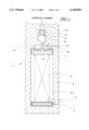
- FIG. 1 is a cross-section through a control shutoff valve modified in conformity with the invention
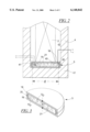
- FIG. 2 is an enlarged view of the compensation element supported at the housing floor of the valve
- FIG. 3 is a partially perspective illustration of the compensation element
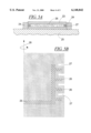
- FIGS. 4a, 4b, 4c, 5a, 5b and 6 depict further exemplary embodiments of compensation elements.
- FIG. 1 shows an inventively modified, outwardly opened valve 1 for the shut-off of the injection pressure built up in the working chamber of a diesel common rail injector.
- the shut-off valve contains a piezo-electric actuator 2 that is supported at a compensation element 3 compensating temperature-conditioned length changes and that is supplied with the required operating voltages via leads 5 conducted out of the valve housing 4.
- a piezo-electric multi-layer stack is particularly suited as the valve drive since this actuator type, in addition to generating the required actuating force of F ⁇ 10 2 -10 5 N, also generates what is still a comparatively great primary stroke at moderate operating voltages (relative length change of the actuator cone ⁇ l/I ⁇ 10 -3 ; I:actuator length).
- the piezo-electric actuator 2 In order to be able to suddenly drop the injection pressure of, typically, p ⁇ 2000 bar built up in the working chamber (not shown) of the injector and also prevailing in the fuel-filled spring chamber 6 of the shut-off valve 1, the piezo-electric actuator 2 is charged within a time span of T ⁇ 100 ⁇ s and is thereby elongated in the axial direction. As soon as the actuating force of the actuator 2 exceeds the opposing forces generated by the saucer spring 7, the closing spring 9 acting on the valve ball 8 and the fuel pressure, the piston 11 guided in the cylindrical housing bore 10 as well as the valve lifter 12 rigidly connected to the piston 11 with the installed O-ring seal moves upward by a distance corresponding to the actuator stroke ⁇ l.
- the lifter 12 lifts the valve ball 8 from its sealing seat 13, so that the fuel can flow unimpeded from the working chamber of the injector via the intake 14 and the spring chamber 6 into the shut-off chamber 15 and can flow off from the latter via the housing bore 16.
- the piezo-electric actuator 2 is discharged in order to suppress the flow-off of the fuel.
- the O-ring sealed piston 11 and the valve lifter 12 move downward into their initial position compelled by the restoring force exerted by the strong saucer spring 7, whereby the closing spring 9 again seats the valve ball 8 at the sealing seat 13.
- the fuel pressure in the spring chamber 6 of the shut-off valve 1 rises again to the preceding value of approximately p ⁇ 2000 bar.
- shut-off valve 1 only works durably and reliably in the described way when the valve lifter 12 respectively assumes a defined vertical attitude with respect to the valve ball 8 during the two periodically occurring charge conditions of the piezo-electric actuator 2.
- the valve lifter 12 must not impede the seating of the valve ball 8 at the sealing seat 13 when the piezo-electric actuator 2 is discharged.
- the lifter 12 must lift the valve ball 8 to such an extent during the shut-off (piezo-electric actuator 2 is charged) that the fuel can flow off with the desired flow rate and the injection pressure prevailing in the spring chamber can dismantle correspondingly fast.
- the piezo-electric actuator 2 is not supported at the housing floor 17 but at the compensation element 3 that compensates for temperature-conditioned length change.
- the compensation element 3 shown magnified in FIGS. 2 and 3 is fit into the cylindrical housing bore 10 with extremely little lateral play (less than 3 ⁇ m) and is arranged on the floor 17 of the valve housing 4 serving as a bearing.
- it is composed of two respectively pot-shaped parts 18/19 (V2A Steel, Invar) as well as of a ring element 20 that connects the two parts 18/19 and yields in a vertical direction.
- the ring element 20 sealing the chamber 21 preferably filled with high-grade hydraulic oil hermetically sealed at the edge side can be fabricated, for example, of nitril butadiene (trade name: Viton).
- this amounts to p 0 100 bar.
- Such a high static pressure prevents hydraulic plate and assures that no gas bubbles deteriorating the stiffness arise in the oil-filled chamber 21 even at low temperatures.
- oil also has a relatively high thermal coefficient of volume expansion of, typically, ⁇ oil ⁇ 10 -3 (1/K).
- ⁇ oil ⁇ 10 -3 (1/K)
- every volumetric expansion of the oil is completely converted into a linear expansion, whereby the linear thermal coefficient of length expansion ⁇ oil then numerically corresponds to the thermal coefficient of volume expansion ( ⁇ oil ⁇ oil ⁇ 10 -3 K -1 ).
- the present invention uses this effect in order to compensate for temperature-conditioned length changes in the shut-off valve 1 using the oil-filled compensation element 3.
- the problem to be solved is then also that the height h of the oil-filled chamber 21 is to be dimensioned such that the unit composed of the piezo-electric actuator 2 and of the compensation element 3 and the part of the valve housing 4 accepting this unit always have exactly the same length regardless of the temperature T. Leaving the length change of the piston 11 and of the valve lifter 12 out of consideration, the following must thus at least approximately apply:
- a fluid column having the volume V 0 A D ⁇ h (h: height of the fluid column) compressed in a rigid cylinder by a piston having the area A D , has a linear spring stiffness c that is dependent on the compression modulus K of the fluid according to the relationship ##EQU2##
- This value of the spring stiffness approximately corresponds to 4.5 times the stiffness of the piezo-electric sintered body (7 ⁇ 7 ⁇ 39 mm 3 ) of c Piezo ⁇ 60 N/ ⁇ m).
- the compensation elements 3 shown in cross-section in FIGS. 4a and 4b are respectively arranged on the floor 17 of a valve housing 4 or on a stiff bearing and are fitted into the cylindrical housing bore 10 with extremely little lateral play. They are respectively composed of an actuator-side, upper part 18, of a bearing-side, lower part 19 and of an element 20 that seals the oil-filled chamber 21 and yields in the vertical direction.
- an elastomer (FIG. 4a) vulcanized to the two parts 18/19 or an O-ring come into consideration as seal element 20.
- this can be arranged (not shown) between the parts 18/19 of the compensation element 3 (FIG. 4b) composed of V2A Steel or can be arranged in a channel of the piston-shaped upper part 18.
- the lower part is preferably fashioned as a flat disk or thin diaphragm.
- FIG. 4c An especially simply construction compensation element 3 is shown in FIG. 4c. It is composed merely of an O-ring-sealed piston 22 that is displaceably guided in the housing bore 10.
- the housing wall 4 acts as holder that prevents lateral evasion.
- the housing floor 17 forms the non-displaceable lower part of the compensation element 3 relative to the actuator 2.
- the oil-filled chamber 21 is located between piston 22 and the housing floor 17.
- the housing 23 (composed of V2A steel) of the compensation element shown in FIG. 5a is arranged exactly fitted in a metal ring 24 or metal frame serving as holder that is rigidly connected to the seat 25.
- the slots, channels or milled portions 27 present in the holder-side chamber wall in the region of the oil-filled volume 26 enable the expansion or, respectively the dilation of the housing 23 in the vertical direction.
- the holder-side chamber wall of the compensation element that is rotational-symmetrical with respect to the axis 28 preferably exhibits a meander-shaped or bellows-like structure in cross-section.
- FIG. 6 shows a compensation element 3 arranged free-standing on a bearing 29 (for example, the floor of a valve housing). It is composed of a metal disk 30 (stainless steel) directly supported at the bearing 29, of a metal disk 31 (stainless steel) at the drive side and of a metal bellows 32 welded to the two metal disks 30/31 that is mechanically rigid in lateral direction. The volume enclosed by the metal disks 30/31 and the corrugated metal bellows 32 thereby forms the compensation chamber 33 that is pressure-filled bubble-free with an oil under vacuum and is sealed by laser welding.
- stainless steel, bronze or a nickel alloy (Hastelloy, Monel), into consideration as bellows material.
- Witzenmann GmbH Metallschlausch-Fabrik-Pforzheim, D-75175 Pforzheim manufactures corresponding metal bellows (smallest inside diameter d i ⁇ 2 mm; wall thickness d w ⁇ 0.02 mm). Since the lateral mechanical stiffness of the metal bellows 32 potentially implemented multi-wall as well exceeds the axial mechanical stiffness by a factor 10 2 -10 3 (c axial ⁇ 1-10 N/mm; c lateral ⁇ 10 2 -10 3 N/mm), holder that prevents lateral expansions of the housing is required for such a compensation element 3.
- the present invention is not limited to the above-described exemplary embodiments.
- the chamber 21 of the compensation element 3 can also be filled with some other fluid instead of oil (mercury, liquid hydrocarbon compound, water), with a grease as well as with a member composed of a plastically deformable material (rubber, plastic).
- the chamber can be filled with a fluid residing under over-pressure.
- a sensor 40 can be arranged in the chamber 21 in order to acquire the respectively prevailing chamber pressure (the inside pressure is a direct measure of the force acting on the bearing).
- the chamber pressure can be set to a defined value by active heating of the medium with a heating element 41 (control of the position of the valve lifter, i.e. active compensation of temperature-conditioned length change).
- the base area or, respectively, the cross-section of the compensation element 3 can have a quadratically or rectangularly configuration.
- the compensation element 3 can be arranged on a bearing (disk with a holder encompassing the compensation element) provided with a thread and screw the bearing to the housing accepting the object.
- the holder 4/24 can be eliminated insofar as the lateral mechanical stiffness of the unfilled compensation element 3 is adequately great (c lateral /C axial ⁇ 100-1000).
- the compensation element can be utilized not only in injection, control and dosing valves but anywhere that temperature-conditioned length change of an object requires compensation.
Abstract
Description
I.sub.p (l+α.sub.p ·ΔT)+h(l+α.sub.oil ·ΔT)=I.sub.G (l+α.sub.G ·ΔT)(1)
h=0.58 mm! (3)
Claims (17)
Applications Claiming Priority (2)
| Application Number | Priority Date | Filing Date | Title |
|---|---|---|---|
| DE19727992 | 1997-07-01 | ||
| DE19727992A DE19727992C2 (en) | 1997-07-01 | 1997-07-01 | Compensation element for compensation of temperature-related changes in length of electromechanical control systems |
Publications (1)
| Publication Number | Publication Date |
|---|---|
| US6148842A true US6148842A (en) | 2000-11-21 |
Family
ID=7834260
Family Applications (1)
| Application Number | Title | Priority Date | Filing Date |
|---|---|---|---|
| US09/108,669 Expired - Fee Related US6148842A (en) | 1997-07-01 | 1998-07-01 | Compensation element for the compensation of temperature-conditioned length changes of an object |
Country Status (3)
| Country | Link |
|---|---|
| US (1) | US6148842A (en) |
| DE (1) | DE19727992C2 (en) |
| FR (1) | FR2765634A1 (en) |
Cited By (43)
| Publication number | Priority date | Publication date | Assignee | Title |
|---|---|---|---|---|
| US6318342B1 (en) * | 1998-06-19 | 2001-11-20 | Robert Bosch Gmbh | Fuel injection valve and pressure sensor combination |
| US6345771B1 (en) | 2000-06-30 | 2002-02-12 | Siemens Automotive Corporation | Multiple stack piezoelectric actuator for a fuel injector |
| US6400066B1 (en) | 2000-06-30 | 2002-06-04 | Siemens Automotive Corporation | Electronic compensator for a piezoelectric actuator |
| DE10141136A1 (en) * | 2001-04-07 | 2002-10-10 | Continental Teves Ag & Co Ohg | Hydraulic valve with smooth piezoelectric actuation, for anti-skid vehicle braking system, includes resiliently-deformable thrust transmission system |
| US20020153429A1 (en) * | 2000-01-28 | 2002-10-24 | Friedrich Boecking | Injection nozzle |
| WO2002095212A1 (en) * | 2001-05-23 | 2002-11-28 | Westport Research Inc. | Directly actuated injection valve |
| US6499471B2 (en) | 2001-06-01 | 2002-12-31 | Siemens Automotive Corporation | Hydraulic compensator for a piezoelectrical fuel injector |
| US6502803B1 (en) * | 1999-09-30 | 2003-01-07 | Robert Bosch Gmbh | Valve for controlling liquids |
| WO2003031797A1 (en) | 2001-10-05 | 2003-04-17 | Siemens Aktiengesellschaft | Nozzle device |
| US6570474B2 (en) | 2000-02-22 | 2003-05-27 | Siemens Automotive Corporation | Magnetostrictive electronic valve timing actuator |
| US20030107013A1 (en) * | 2001-12-12 | 2003-06-12 | Alfred Pappo | Variable valve with an electromagnetically-elongated actuator |
| US20030214199A1 (en) * | 1997-02-07 | 2003-11-20 | Sri International, A California Corporation | Electroactive polymer devices for controlling fluid flow |
| US6676030B2 (en) | 2000-10-11 | 2004-01-13 | Siemens Automotive Corporation | Compensator assembly having a flexible diaphragm for a fuel injector and method |
| US20040031862A1 (en) * | 2001-08-20 | 2004-02-19 | Andreas Eichendorf | Fuel injector |
| US20040069874A1 (en) * | 2000-11-13 | 2004-04-15 | Czimmek Perry Robert | Magneto-hydraulic compensator for a fuel injector |
| US6749127B2 (en) | 2002-02-11 | 2004-06-15 | Siemens Vdo Automotive Corporation | Method of filling fluid in a thermal compensator |
| US6766965B2 (en) | 2001-08-31 | 2004-07-27 | Siemens Automotive Corporation | Twin tube hydraulic compensator for a fuel injector |
| US20040195389A1 (en) * | 2001-10-04 | 2004-10-07 | Siemens Aktiengesellschaft | Injector |
| EP1473460A1 (en) * | 1999-10-15 | 2004-11-03 | Westport Research Inc. | Directly actuated injection valve |
| US6814314B1 (en) * | 1999-10-02 | 2004-11-09 | Robert Bosch Gmbh | Fuel injection valve |
| WO2005024223A1 (en) * | 2003-09-08 | 2005-03-17 | Siemens Aktiengesellschaft | Injection valve for injecting fuel into an internal combustion engine |
| EP1524427A1 (en) * | 2003-10-09 | 2005-04-20 | Siemens Aktiengesellschaft | Piezoelectric actuator with compensator |
| US20050146248A1 (en) * | 2003-11-20 | 2005-07-07 | Moler Jeffery B. | Integral thermal compensation for an electro-mechanical actuator |
| US20070114881A1 (en) * | 2005-11-18 | 2007-05-24 | Jensen Eric L | Actuator with amplified stroke length |
| US20080011972A1 (en) * | 1999-05-07 | 2008-01-17 | Wilhelm Frank | Procedure For Positioning The Actuating Drive In A Fuel Injector And Device For Performing The Procedure |
| EP1884655A1 (en) * | 1999-10-15 | 2008-02-06 | Westport Power Inc. | Directly actuated injection valve |
| US20080245985A1 (en) * | 1999-07-20 | 2008-10-09 | Sri International | Electroactive polymer devices for controlling fluid flow |
| US20090202694A1 (en) * | 2008-02-08 | 2009-08-13 | Conagra Foods Lamb Weston, Inc. | Apparatus and method for slicing vegetables |
| US20100065022A1 (en) * | 2006-12-12 | 2010-03-18 | Erik Toner | Method for operating an injector |
| US20100229833A1 (en) * | 2009-03-10 | 2010-09-16 | Jeffrey Bluen | Reverse operating nonlinear spring |
| WO2011144610A1 (en) | 2010-05-17 | 2011-11-24 | Mindray Medical Sweden Ab | Mechanical temperature compensation means, method for assembly said means and method for mechanically temperature compensating |
| US20120328748A1 (en) * | 2006-12-06 | 2012-12-27 | Rhea Vendors S.P.A. | Beverage dispensing machine and operating method |
| US8664832B2 (en) | 2010-05-18 | 2014-03-04 | Mindray Medical Sweden Ab | Mechanical temperature compensation methods and devices |
| US20140306034A1 (en) * | 2013-04-11 | 2014-10-16 | Robert Bosch Gmbh | Valve for metering fluid |
| US9195058B2 (en) | 2011-03-22 | 2015-11-24 | Parker-Hannifin Corporation | Electroactive polymer actuator lenticular system |
| US9231186B2 (en) | 2009-04-11 | 2016-01-05 | Parker-Hannifin Corporation | Electro-switchable polymer film assembly and use thereof |
| US9425383B2 (en) | 2007-06-29 | 2016-08-23 | Parker-Hannifin Corporation | Method of manufacturing electroactive polymer transducers for sensory feedback applications |
| US9553254B2 (en) | 2011-03-01 | 2017-01-24 | Parker-Hannifin Corporation | Automated manufacturing processes for producing deformable polymer devices and films |
| US9590193B2 (en) | 2012-10-24 | 2017-03-07 | Parker-Hannifin Corporation | Polymer diode |
| US9761790B2 (en) | 2012-06-18 | 2017-09-12 | Parker-Hannifin Corporation | Stretch frame for stretching process |
| US9876160B2 (en) | 2012-03-21 | 2018-01-23 | Parker-Hannifin Corporation | Roll-to-roll manufacturing processes for producing self-healing electroactive polymer devices |
| EP2444649B1 (en) * | 2010-10-19 | 2020-04-01 | Robert Bosch GmbH | Fuel injector, in particular common rail injection system |
| US11261852B2 (en) * | 2019-01-09 | 2022-03-01 | Pratt & Whitney Canada Corp. | Thermal actuator |
Families Citing this family (16)
| Publication number | Priority date | Publication date | Assignee | Title |
|---|---|---|---|---|
| DE19826341A1 (en) * | 1998-06-12 | 1999-12-16 | Bosch Gmbh Robert | Valve for controlling liquids |
| DE19909106C2 (en) * | 1999-03-02 | 2001-08-23 | Siemens Ag | Temperature compensated piezoelectric actuator unit |
| DE19940055C1 (en) * | 1999-08-24 | 2001-04-05 | Siemens Ag | Dosing valve |
| US6298829B1 (en) | 1999-10-15 | 2001-10-09 | Westport Research Inc. | Directly actuated injection valve |
| US6584958B2 (en) | 1999-10-15 | 2003-07-01 | Westport Research Inc. | Directly actuated injection valve with a ferromagnetic needle |
| US6564777B2 (en) | 1999-10-15 | 2003-05-20 | Westport Research Inc. | Directly actuated injection valve with a composite needle |
| DE10040239B4 (en) * | 2000-08-17 | 2009-04-02 | Continental Automotive Gmbh | Noise-damped actuator unit |
| DE10057495B4 (en) * | 2000-11-20 | 2005-08-04 | Siemens Ag | Injector housing with an actuator unit |
| DE10225686B4 (en) * | 2002-06-10 | 2005-08-04 | Siemens Ag | Hubübertragungselement for an injection valve |
| DE10254985A1 (en) * | 2002-11-26 | 2004-06-03 | Robert Bosch Gmbh | Valve for controlling liquids with a nozzle and a control module |
| DE10345203A1 (en) * | 2003-09-29 | 2005-05-04 | Bosch Gmbh Robert | Fuel injector |
| DE102004034520B4 (en) * | 2004-07-16 | 2006-11-02 | Siemens Ag | Piezo-operated actuator |
| DE102005015256A1 (en) * | 2005-04-04 | 2006-10-05 | Robert Bosch Gmbh | Piezoelectric actuator with labyrinth seal for use in fuel injection valve, has plastic sealing formed with projections that are inserted and completely fill circulating grooves formed on head or base portion of piezoelectric component |
| DE102005024049A1 (en) | 2005-05-25 | 2006-11-30 | Robert Bosch Gmbh | Fuel injection device, in particular for an internal combustion engine with direct fuel injection |
| DE102013102741A1 (en) * | 2013-03-18 | 2014-09-18 | Leuze Electronic Gmbh & Co. Kg | Optical sensor |
| DE102019121679A1 (en) * | 2019-08-12 | 2021-02-18 | Vermes Microdispensing GmbH | Dosing system with adjustable actuator |
Citations (17)
| Publication number | Priority date | Publication date | Assignee | Title |
|---|---|---|---|---|
| US1702186A (en) * | 1929-02-12 | Expansion valve | ||
| US1992789A (en) * | 1931-04-13 | 1935-02-26 | Eaton Mfg Co | Water heater |
| US3949849A (en) * | 1974-11-18 | 1976-04-13 | General Motors Corporation | Viscous fluid clutch |
| GB2094940A (en) * | 1981-02-18 | 1982-09-22 | Nissan Motor | Piezo-electric valve |
| GB2112907A (en) * | 1981-12-30 | 1983-07-27 | Actrol Ind Pty Ltd | Valve and system incorporating same |
| US4535914A (en) * | 1984-02-21 | 1985-08-20 | Coty Raymond J A | Automatic larvicide dispenser |
| US4550744A (en) * | 1982-11-16 | 1985-11-05 | Nippon Soken, Inc. | Piezoelectric hydraulic control valve |
| DE3533085A1 (en) * | 1985-09-17 | 1987-03-26 | Bosch Gmbh Robert | METERING VALVE FOR DOSING LIQUIDS OR GASES |
| US4732216A (en) * | 1986-04-21 | 1988-03-22 | Central Sprinkler Corporation | Quick release mechanism for sprinkler head |
| US4995587A (en) * | 1989-11-03 | 1991-02-26 | Martin Marietta Corporation | Motion amplifier employing a dual piston arrangement |
| US5207737A (en) * | 1992-02-27 | 1993-05-04 | Landis & Gyr Powers, Inc. | Analog output electro-pneumatic transducer |
| US5318268A (en) * | 1993-06-10 | 1994-06-07 | Eaton Corporation | Thermally actuated valve with ambient temperature compensation |
| DE19519191A1 (en) * | 1995-05-24 | 1996-12-19 | Siemens Ag | Injector |
| DE19540155A1 (en) * | 1995-10-27 | 1997-04-30 | Huber Motorenbau Inst | Servo valve for an injection nozzle |
| US5780958A (en) * | 1995-11-03 | 1998-07-14 | Aura Systems, Inc. | Piezoelectric vibrating device |
| US5810255A (en) * | 1995-08-29 | 1998-09-22 | Robert Bosch Gmbh | Clamping device for a piesoelectric actuator of a fuel injection valve for internal combustion engines |
| US5988210A (en) * | 1997-03-27 | 1999-11-23 | Aera Japan Ltd | Flow control valve utilizing sonic nozzle |
Family Cites Families (11)
| Publication number | Priority date | Publication date | Assignee | Title |
|---|---|---|---|---|
| JPH0656162B2 (en) * | 1987-03-03 | 1994-07-27 | トヨタ自動車株式会社 | Variable stroke device |
| US5031841A (en) * | 1989-02-28 | 1991-07-16 | Volkswagen Ag | Metering valve, particularly fuel injection valve |
| DE4005455A1 (en) * | 1989-02-28 | 1990-08-30 | Volkswagen Ag | Dosing valve for vehicle IC engine fuel injection - has piezoelectric actuator and spring membrane seal for closing force |
| EP0477400B1 (en) * | 1990-09-25 | 2000-04-26 | Siemens Aktiengesellschaft | Device for compensating the tolerance in the lift direction of the displacement transformer of a piezoelectric actuator |
| WO1993006625A1 (en) * | 1991-09-27 | 1993-04-01 | Siemens Aktiengesellschaft | Hydraulic displacement transformer for the piezoelectric actuator of an inlet valve |
| DE4306072C2 (en) * | 1993-02-26 | 1994-12-08 | Siemens Ag | Device for opening and closing a passage opening in a housing |
| DE19543131A1 (en) * | 1995-11-18 | 1996-10-02 | Heinz Schmidt | Regulating distance booster for piezoelectric and magnetostrictive power converters |
| DE19646847A1 (en) * | 1996-11-13 | 1997-06-12 | Heinz Schmidt | Modular hydraulic regulating distance transformer |
| DE19708304C2 (en) * | 1997-02-28 | 1999-09-30 | Siemens Ag | Movement transmission device and injection valve with a movement transmission device |
| DE19714292C2 (en) * | 1997-04-07 | 2000-10-26 | Siemens Ag | Device for transmitting a deflection of an actuator |
| DE29708546U1 (en) * | 1997-05-14 | 1998-09-10 | Fev Motorentech Gmbh & Co Kg | Electric solid state actuator with hydraulic transmission |
-
1997
- 1997-07-01 DE DE19727992A patent/DE19727992C2/en not_active Expired - Fee Related
-
1998
- 1998-06-26 FR FR9808133A patent/FR2765634A1/en not_active Withdrawn
- 1998-07-01 US US09/108,669 patent/US6148842A/en not_active Expired - Fee Related
Patent Citations (18)
| Publication number | Priority date | Publication date | Assignee | Title |
|---|---|---|---|---|
| US1702186A (en) * | 1929-02-12 | Expansion valve | ||
| US1992789A (en) * | 1931-04-13 | 1935-02-26 | Eaton Mfg Co | Water heater |
| US3949849A (en) * | 1974-11-18 | 1976-04-13 | General Motors Corporation | Viscous fluid clutch |
| GB2094940A (en) * | 1981-02-18 | 1982-09-22 | Nissan Motor | Piezo-electric valve |
| GB2112907A (en) * | 1981-12-30 | 1983-07-27 | Actrol Ind Pty Ltd | Valve and system incorporating same |
| US4550744A (en) * | 1982-11-16 | 1985-11-05 | Nippon Soken, Inc. | Piezoelectric hydraulic control valve |
| US4535914A (en) * | 1984-02-21 | 1985-08-20 | Coty Raymond J A | Automatic larvicide dispenser |
| US4725002A (en) * | 1985-09-17 | 1988-02-16 | Robert Bosch Gmbh | Measuring valve for dosing liquids or gases |
| DE3533085A1 (en) * | 1985-09-17 | 1987-03-26 | Bosch Gmbh Robert | METERING VALVE FOR DOSING LIQUIDS OR GASES |
| US4732216A (en) * | 1986-04-21 | 1988-03-22 | Central Sprinkler Corporation | Quick release mechanism for sprinkler head |
| US4995587A (en) * | 1989-11-03 | 1991-02-26 | Martin Marietta Corporation | Motion amplifier employing a dual piston arrangement |
| US5207737A (en) * | 1992-02-27 | 1993-05-04 | Landis & Gyr Powers, Inc. | Analog output electro-pneumatic transducer |
| US5318268A (en) * | 1993-06-10 | 1994-06-07 | Eaton Corporation | Thermally actuated valve with ambient temperature compensation |
| DE19519191A1 (en) * | 1995-05-24 | 1996-12-19 | Siemens Ag | Injector |
| US5810255A (en) * | 1995-08-29 | 1998-09-22 | Robert Bosch Gmbh | Clamping device for a piesoelectric actuator of a fuel injection valve for internal combustion engines |
| DE19540155A1 (en) * | 1995-10-27 | 1997-04-30 | Huber Motorenbau Inst | Servo valve for an injection nozzle |
| US5780958A (en) * | 1995-11-03 | 1998-07-14 | Aura Systems, Inc. | Piezoelectric vibrating device |
| US5988210A (en) * | 1997-03-27 | 1999-11-23 | Aera Japan Ltd | Flow control valve utilizing sonic nozzle |
Cited By (67)
| Publication number | Priority date | Publication date | Assignee | Title |
|---|---|---|---|---|
| US7320457B2 (en) * | 1997-02-07 | 2008-01-22 | Sri International | Electroactive polymer devices for controlling fluid flow |
| US20030214199A1 (en) * | 1997-02-07 | 2003-11-20 | Sri International, A California Corporation | Electroactive polymer devices for controlling fluid flow |
| US6318342B1 (en) * | 1998-06-19 | 2001-11-20 | Robert Bosch Gmbh | Fuel injection valve and pressure sensor combination |
| US8720852B2 (en) * | 1999-05-07 | 2014-05-13 | Continental Automotive Gmbh | Procedure for positioning the actuating drive in a fuel injector and device for performing the procedure |
| US20080011972A1 (en) * | 1999-05-07 | 2008-01-17 | Wilhelm Frank | Procedure For Positioning The Actuating Drive In A Fuel Injector And Device For Performing The Procedure |
| US20090200501A1 (en) * | 1999-07-20 | 2009-08-13 | Sri International | Electroactive polymer devices for controlling fluid flow |
| US7537197B2 (en) | 1999-07-20 | 2009-05-26 | Sri International | Electroactive polymer devices for controlling fluid flow |
| US20080245985A1 (en) * | 1999-07-20 | 2008-10-09 | Sri International | Electroactive polymer devices for controlling fluid flow |
| US7703742B2 (en) | 1999-07-20 | 2010-04-27 | Sri International | Electroactive polymer devices for controlling fluid flow |
| US20100176322A1 (en) * | 1999-07-20 | 2010-07-15 | Sri International | Electroactive polymer devices for controlling fluid flow |
| US7971850B2 (en) | 1999-07-20 | 2011-07-05 | Sri International | Electroactive polymer devices for controlling fluid flow |
| US6502803B1 (en) * | 1999-09-30 | 2003-01-07 | Robert Bosch Gmbh | Valve for controlling liquids |
| US6814314B1 (en) * | 1999-10-02 | 2004-11-09 | Robert Bosch Gmbh | Fuel injection valve |
| EP1473460A1 (en) * | 1999-10-15 | 2004-11-03 | Westport Research Inc. | Directly actuated injection valve |
| EP1884655A1 (en) * | 1999-10-15 | 2008-02-06 | Westport Power Inc. | Directly actuated injection valve |
| US20020153429A1 (en) * | 2000-01-28 | 2002-10-24 | Friedrich Boecking | Injection nozzle |
| US6570474B2 (en) | 2000-02-22 | 2003-05-27 | Siemens Automotive Corporation | Magnetostrictive electronic valve timing actuator |
| US6702250B2 (en) | 2000-02-22 | 2004-03-09 | Siemens Automotive Corporation | Magnetostrictive electronic valve timing actuator |
| US6650032B2 (en) | 2000-06-30 | 2003-11-18 | Siemens Automotive Corporation | Electronic compensator for a piezoelectric actuator |
| US6345771B1 (en) | 2000-06-30 | 2002-02-12 | Siemens Automotive Corporation | Multiple stack piezoelectric actuator for a fuel injector |
| US6400066B1 (en) | 2000-06-30 | 2002-06-04 | Siemens Automotive Corporation | Electronic compensator for a piezoelectric actuator |
| US6676030B2 (en) | 2000-10-11 | 2004-01-13 | Siemens Automotive Corporation | Compensator assembly having a flexible diaphragm for a fuel injector and method |
| US6755353B2 (en) | 2000-10-11 | 2004-06-29 | Siemens Automotive Corporation | Compensator assembly having a pressure responsive valve for a solid state actuator of a fuel injector |
| US6739528B2 (en) | 2000-10-11 | 2004-05-25 | Siemens Automotive Corporation | Compensator assembly having a flexible diaphragm and an internal filling tube for a fuel injector and method |
| US6715695B2 (en) * | 2000-10-11 | 2004-04-06 | Siemens Automotive Corporation | Pressure responsive valve for a compensator in a solid state actuator |
| US6676035B2 (en) | 2000-10-11 | 2004-01-13 | Siemens Automotive Corporation | Dual-spring compensator assembly for a fuel injector and method |
| US20040069874A1 (en) * | 2000-11-13 | 2004-04-15 | Czimmek Perry Robert | Magneto-hydraulic compensator for a fuel injector |
| US7048209B2 (en) | 2000-11-13 | 2006-05-23 | Siemens Vdo Automotive Corporation | Magneto-hydraulic compensator for a fuel injector |
| DE10141136A1 (en) * | 2001-04-07 | 2002-10-10 | Continental Teves Ag & Co Ohg | Hydraulic valve with smooth piezoelectric actuation, for anti-skid vehicle braking system, includes resiliently-deformable thrust transmission system |
| WO2002095212A1 (en) * | 2001-05-23 | 2002-11-28 | Westport Research Inc. | Directly actuated injection valve |
| US6499471B2 (en) | 2001-06-01 | 2002-12-31 | Siemens Automotive Corporation | Hydraulic compensator for a piezoelectrical fuel injector |
| US6948667B2 (en) * | 2001-08-20 | 2005-09-27 | Robert Bosch Gmbh | Fuel injector |
| US20040031862A1 (en) * | 2001-08-20 | 2004-02-19 | Andreas Eichendorf | Fuel injector |
| US6766965B2 (en) | 2001-08-31 | 2004-07-27 | Siemens Automotive Corporation | Twin tube hydraulic compensator for a fuel injector |
| US6974089B2 (en) | 2001-10-04 | 2005-12-13 | Siemens Aktiengesellschaft | Injector |
| US20040195389A1 (en) * | 2001-10-04 | 2004-10-07 | Siemens Aktiengesellschaft | Injector |
| DE10149286C2 (en) * | 2001-10-05 | 2003-12-11 | Siemens Ag | Nozzle device, in particular for fuel injection |
| WO2003031797A1 (en) | 2001-10-05 | 2003-04-17 | Siemens Aktiengesellschaft | Nozzle device |
| US20030107013A1 (en) * | 2001-12-12 | 2003-06-12 | Alfred Pappo | Variable valve with an electromagnetically-elongated actuator |
| US6749127B2 (en) | 2002-02-11 | 2004-06-15 | Siemens Vdo Automotive Corporation | Method of filling fluid in a thermal compensator |
| WO2005024223A1 (en) * | 2003-09-08 | 2005-03-17 | Siemens Aktiengesellschaft | Injection valve for injecting fuel into an internal combustion engine |
| EP1524427A1 (en) * | 2003-10-09 | 2005-04-20 | Siemens Aktiengesellschaft | Piezoelectric actuator with compensator |
| US20050146248A1 (en) * | 2003-11-20 | 2005-07-07 | Moler Jeffery B. | Integral thermal compensation for an electro-mechanical actuator |
| US7126259B2 (en) | 2003-11-20 | 2006-10-24 | Viking Technologies, L.C. | Integral thermal compensation for an electro-mechanical actuator |
| US20070114881A1 (en) * | 2005-11-18 | 2007-05-24 | Jensen Eric L | Actuator with amplified stroke length |
| US7307371B2 (en) | 2005-11-18 | 2007-12-11 | Delphi Technologies, Inc. | Actuator with amplified stroke length |
| US11154160B2 (en) * | 2006-12-06 | 2021-10-26 | RHEAVENDORS SERVICES SpA. | Beverage dispensing machine and operating method |
| US10117541B2 (en) * | 2006-12-06 | 2018-11-06 | RHEAVENDORS SERVI CES, S.p.A. | Beverage dispensing machine and operating method |
| US20120328748A1 (en) * | 2006-12-06 | 2012-12-27 | Rhea Vendors S.P.A. | Beverage dispensing machine and operating method |
| US20100065022A1 (en) * | 2006-12-12 | 2010-03-18 | Erik Toner | Method for operating an injector |
| US8082903B2 (en) * | 2006-12-12 | 2011-12-27 | Robert Bosch Gmbh | Method for operating an injector |
| US9425383B2 (en) | 2007-06-29 | 2016-08-23 | Parker-Hannifin Corporation | Method of manufacturing electroactive polymer transducers for sensory feedback applications |
| US20090202694A1 (en) * | 2008-02-08 | 2009-08-13 | Conagra Foods Lamb Weston, Inc. | Apparatus and method for slicing vegetables |
| US8402951B2 (en) * | 2009-03-10 | 2013-03-26 | Transonic Combustion, Inc. | Reverse operating nonlinear spring |
| US20100229833A1 (en) * | 2009-03-10 | 2010-09-16 | Jeffrey Bluen | Reverse operating nonlinear spring |
| US9231186B2 (en) | 2009-04-11 | 2016-01-05 | Parker-Hannifin Corporation | Electro-switchable polymer film assembly and use thereof |
| WO2011144610A1 (en) | 2010-05-17 | 2011-11-24 | Mindray Medical Sweden Ab | Mechanical temperature compensation means, method for assembly said means and method for mechanically temperature compensating |
| US8664832B2 (en) | 2010-05-18 | 2014-03-04 | Mindray Medical Sweden Ab | Mechanical temperature compensation methods and devices |
| EP2444649B1 (en) * | 2010-10-19 | 2020-04-01 | Robert Bosch GmbH | Fuel injector, in particular common rail injection system |
| US9553254B2 (en) | 2011-03-01 | 2017-01-24 | Parker-Hannifin Corporation | Automated manufacturing processes for producing deformable polymer devices and films |
| US9195058B2 (en) | 2011-03-22 | 2015-11-24 | Parker-Hannifin Corporation | Electroactive polymer actuator lenticular system |
| US9876160B2 (en) | 2012-03-21 | 2018-01-23 | Parker-Hannifin Corporation | Roll-to-roll manufacturing processes for producing self-healing electroactive polymer devices |
| US9761790B2 (en) | 2012-06-18 | 2017-09-12 | Parker-Hannifin Corporation | Stretch frame for stretching process |
| US9590193B2 (en) | 2012-10-24 | 2017-03-07 | Parker-Hannifin Corporation | Polymer diode |
| US20140306034A1 (en) * | 2013-04-11 | 2014-10-16 | Robert Bosch Gmbh | Valve for metering fluid |
| US9382884B2 (en) * | 2013-04-11 | 2016-07-05 | Robert Bosch Gmbh | Valve for metering fluid |
| US11261852B2 (en) * | 2019-01-09 | 2022-03-01 | Pratt & Whitney Canada Corp. | Thermal actuator |
Also Published As
| Publication number | Publication date |
|---|---|
| DE19727992A1 (en) | 1999-01-07 |
| FR2765634A1 (en) | 1999-01-08 |
| DE19727992C2 (en) | 1999-05-20 |
Similar Documents
| Publication | Publication Date | Title |
|---|---|---|
| US6148842A (en) | Compensation element for the compensation of temperature-conditioned length changes of an object | |
| JP4052383B2 (en) | Pressure response valve for compensator of solid state actuator | |
| US7886993B2 (en) | Injection valve | |
| US6119952A (en) | Device and method for dosing fluid | |
| JP4002229B2 (en) | Fuel injection valve | |
| KR20000015898A (en) | Fuel injection valve with a piezo-electric or magnetostrictive actuator | |
| US5875632A (en) | Electrohydraulic drive | |
| KR100881583B1 (en) | Fuel injection valve | |
| US20030150939A1 (en) | Method of filling and degassifying fluid in a hydraulic compensator for a fuel injector | |
| EP1464828B1 (en) | Thermal compensator unit for use in a metering device | |
| JPH0419201Y2 (en) |
Legal Events
| Date | Code | Title | Description |
|---|---|---|---|
| AS | Assignment |
Owner name: SIEMENS AKTIENGESELLSCHAFT, GERMANY Free format text: ASSIGNMENT OF ASSIGNORS INTEREST;ASSIGNORS:KAPPEL, ANDREAS;MOCK, RANDOLF;MEIXNER, HANS;REEL/FRAME:009449/0284;SIGNING DATES FROM 19980813 TO 19980817 |
|
| FEPP | Fee payment procedure |
Free format text: PAYOR NUMBER ASSIGNED (ORIGINAL EVENT CODE: ASPN); ENTITY STATUS OF PATENT OWNER: LARGE ENTITY |
|
| FPAY | Fee payment |
Year of fee payment: 4 |
|
| FPAY | Fee payment |
Year of fee payment: 8 |
|
| REMI | Maintenance fee reminder mailed | ||
| LAPS | Lapse for failure to pay maintenance fees | ||
| STCH | Information on status: patent discontinuation |
Free format text: PATENT EXPIRED DUE TO NONPAYMENT OF MAINTENANCE FEES UNDER 37 CFR 1.362 |
|
| FP | Lapsed due to failure to pay maintenance fee |
Effective date: 20121121 |