US6148925A - Method of making a conductive downhole wire line system - Google Patents
Method of making a conductive downhole wire line system Download PDFInfo
- Publication number
- US6148925A US6148925A US09/249,547 US24954799A US6148925A US 6148925 A US6148925 A US 6148925A US 24954799 A US24954799 A US 24954799A US 6148925 A US6148925 A US 6148925A
- Authority
- US
- United States
- Prior art keywords
- tubing
- conductor
- weight
- chain
- fall
- Prior art date
- Legal status (The legal status is an assumption and is not a legal conclusion. Google has not performed a legal analysis and makes no representation as to the accuracy of the status listed.)
- Expired - Lifetime
Links
- 238000004519 manufacturing process Methods 0.000 title description 9
- 239000004020 conductor Substances 0.000 claims abstract description 143
- 238000000034 method Methods 0.000 claims abstract description 43
- 230000005484 gravity Effects 0.000 claims abstract description 15
- 239000002184 metal Substances 0.000 claims abstract description 12
- 229910052751 metal Inorganic materials 0.000 claims abstract description 12
- 238000004804 winding Methods 0.000 claims abstract 2
- 230000001105 regulatory effect Effects 0.000 claims description 7
- 239000013307 optical fiber Substances 0.000 claims description 6
- 230000001276 controlling effect Effects 0.000 claims description 3
- 239000000463 material Substances 0.000 description 6
- 230000008901 benefit Effects 0.000 description 5
- 230000006870 function Effects 0.000 description 3
- 230000006872 improvement Effects 0.000 description 3
- 238000009413 insulation Methods 0.000 description 3
- 238000012856 packing Methods 0.000 description 3
- 230000008569 process Effects 0.000 description 3
- 229910001369 Brass Inorganic materials 0.000 description 2
- RYGMFSIKBFXOCR-UHFFFAOYSA-N Copper Chemical compound [Cu] RYGMFSIKBFXOCR-UHFFFAOYSA-N 0.000 description 2
- 229910000990 Ni alloy Inorganic materials 0.000 description 2
- PXHVJJICTQNCMI-UHFFFAOYSA-N Nickel Chemical compound [Ni] PXHVJJICTQNCMI-UHFFFAOYSA-N 0.000 description 2
- 239000010951 brass Substances 0.000 description 2
- 238000007796 conventional method Methods 0.000 description 2
- 229920001971 elastomer Polymers 0.000 description 2
- 229910001293 incoloy Inorganic materials 0.000 description 2
- 238000003780 insertion Methods 0.000 description 2
- 230000037431 insertion Effects 0.000 description 2
- 238000012986 modification Methods 0.000 description 2
- 230000004048 modification Effects 0.000 description 2
- 229920001721 polyimide Polymers 0.000 description 2
- 239000000047 product Substances 0.000 description 2
- 238000005482 strain hardening Methods 0.000 description 2
- 238000003466 welding Methods 0.000 description 2
- 229910000831 Steel Inorganic materials 0.000 description 1
- 238000000137 annealing Methods 0.000 description 1
- 125000003118 aryl group Chemical group 0.000 description 1
- 230000000712 assembly Effects 0.000 description 1
- 238000000429 assembly Methods 0.000 description 1
- 239000011324 bead Substances 0.000 description 1
- 230000015572 biosynthetic process Effects 0.000 description 1
- 238000005253 cladding Methods 0.000 description 1
- 239000011248 coating agent Substances 0.000 description 1
- 238000000576 coating method Methods 0.000 description 1
- 238000002788 crimping Methods 0.000 description 1
- 230000000694 effects Effects 0.000 description 1
- 239000000806 elastomer Substances 0.000 description 1
- 239000012467 final product Substances 0.000 description 1
- 239000012530 fluid Substances 0.000 description 1
- 229910052759 nickel Inorganic materials 0.000 description 1
- 239000004033 plastic Substances 0.000 description 1
- 229920003223 poly(pyromellitimide-1,4-diphenyl ether) Polymers 0.000 description 1
- 238000005086 pumping Methods 0.000 description 1
- 238000007670 refining Methods 0.000 description 1
- 239000011347 resin Substances 0.000 description 1
- 229920005989 resin Polymers 0.000 description 1
- 230000000284 resting effect Effects 0.000 description 1
- 238000005096 rolling process Methods 0.000 description 1
- 238000007789 sealing Methods 0.000 description 1
- 239000010935 stainless steel Substances 0.000 description 1
- 229910001256 stainless steel alloy Inorganic materials 0.000 description 1
- 239000010959 steel Substances 0.000 description 1
Images


Classifications
-
- E—FIXED CONSTRUCTIONS
- E21—EARTH DRILLING; MINING
- E21B—EARTH DRILLING, e.g. DEEP DRILLING; OBTAINING OIL, GAS, WATER, SOLUBLE OR MELTABLE MATERIALS OR A SLURRY OF MINERALS FROM WELLS
- E21B17/00—Drilling rods or pipes; Flexible drill strings; Kellies; Drill collars; Sucker rods; Cables; Casings; Tubings
- E21B17/20—Flexible or articulated drilling pipes, e.g. flexible or articulated rods, pipes or cables
- E21B17/206—Flexible or articulated drilling pipes, e.g. flexible or articulated rods, pipes or cables with conductors, e.g. electrical, optical
-
- E—FIXED CONSTRUCTIONS
- E21—EARTH DRILLING; MINING
- E21B—EARTH DRILLING, e.g. DEEP DRILLING; OBTAINING OIL, GAS, WATER, SOLUBLE OR MELTABLE MATERIALS OR A SLURRY OF MINERALS FROM WELLS
- E21B19/00—Handling rods, casings, tubes or the like outside the borehole, e.g. in the derrick; Apparatus for feeding the rods or cables
- E21B19/08—Apparatus for feeding the rods or cables; Apparatus for increasing or decreasing the pressure on the drilling tool; Apparatus for counterbalancing the weight of the rods
- E21B19/089—Apparatus for feeding the rods or cables; Apparatus for increasing or decreasing the pressure on the drilling tool; Apparatus for counterbalancing the weight of the rods with a spring or an additional weight
-
- E—FIXED CONSTRUCTIONS
- E21—EARTH DRILLING; MINING
- E21B—EARTH DRILLING, e.g. DEEP DRILLING; OBTAINING OIL, GAS, WATER, SOLUBLE OR MELTABLE MATERIALS OR A SLURRY OF MINERALS FROM WELLS
- E21B19/00—Handling rods, casings, tubes or the like outside the borehole, e.g. in the derrick; Apparatus for feeding the rods or cables
- E21B19/22—Handling reeled pipe or rod units, e.g. flexible drilling pipes
-
- E—FIXED CONSTRUCTIONS
- E21—EARTH DRILLING; MINING
- E21B—EARTH DRILLING, e.g. DEEP DRILLING; OBTAINING OIL, GAS, WATER, SOLUBLE OR MELTABLE MATERIALS OR A SLURRY OF MINERALS FROM WELLS
- E21B23/00—Apparatus for displacing, setting, locking, releasing, or removing tools, packers or the like in the boreholes or wells
- E21B23/14—Apparatus for displacing, setting, locking, releasing, or removing tools, packers or the like in the boreholes or wells for displacing a cable or cable-operated tool, e.g. for logging or perforating operations in deviated wells
Definitions
- This invention relates to downhole wire line systems and, in particular, to a method of making a wire line system that includes small-diameter tubing with one or more signal and/or power conductors extending through the tube, and articles of manufacture useful in the method.
- Downhole instruments or tools for subterranean wells are lowered down a well bore and operated in a subterranean reservoir to measure, for example, formation characteristics such as bottom hole pressures and temperatures as a function of time, and to perform many other measuring, control and operational tasks in a well.
- the wire line is formed of coiled metal tubing ranging from 1/8"-1/2" in diameter, within which one or more conductors capable of transmitting a signal and/or power are located. These conductors can be insulated conductor wires, optical fibers or any other conductor capable of transmitting signals and/or power to or from a downhole location.
- wire line tubing of this type comes in lengths greater than 10,000 feet, up to and longer than 20,000 feet, there has been difficulty in inserting the conductor in such lengths of tubing.
- the conductor can either be in the form of an insulated conductor wire, optical fibers, other conductors for conducting signals and/or power, or some combination thereof.
- the invention includes the steps of inserting the tubing into a substantially vertical passageway such as a well bore, and providing an open upper end of the tubing that is accessible to an operator. The leading end of the conductor is inserted into the upper end of the tubing.
- the leading end of the conductor includes an elongated weight connected to the conductor.
- the weight must be heavy enough to straighten the conductor so it can fall though the coiled tubing.
- the weight must also be flexible enough to move through small bends or other irregularities in the coiled tubing.
- a weight capable of performing these functions is one that has essentially no stiffness so that it can fall freely through irregularities in the coiled tubing without imparting a side load onto the inner surface of the coiled tubing, which would prevent further downward movement.
- a weight can be formed of an elongated segmented structure such as a chain with interlocking links or the like.
- the weight In embodiments of the invention where the weight must be pushed initially into the coiled tubing, the weight must have a minimum bend radius that is great enough to prevent the segments of the weight from bunching up or jamming when a bend or other irregularity is encountered, but which has essentially no stiffness and does not impart a side load until the minimum bend radius is reached.
- a preferred form of such a weight is a chain with interlocking links that has been roll-formed to provide the characteristics described above.
- a push tool can be used to assist the initial insertion of the chain into the tubing until there is enough weight in the tubing to allow the weight to fall by gravity and pull the conductor into the tubing.
- the helical pitch of the coiled tubing is regulated so that the frictional contact between the outer surface of the conductor and the inner surface of the tubing is great enough to support the weight and conductor for preventing the conductor from breaking.
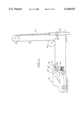
- FIG. 1 is a schematic view of a conductive wire line being run into an underground well
- FIG. 2 is a sectional view of an insulated conductor inside a section of coiled metal tubing of the conductive wire line shown in FIG. 1;
- FIG. 3 is a schematic view of the conventional prior art method of forming conductive wire line
- FIG. 4 is a schematic view of dies forming a strip of metal into coiled tubing in accordance with the method of FIG. 3;
- FIG. 5 is a schematic view, in accordance with the present invention, of conductor being inserted into coiled tubing that has been run into an underground well from a conventional wire line truck;
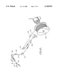
- FIG. 6 is a plan view of the outer surface of the downhole end of the coiled tubing in FIG. 5, with its outer surface shaped by a forming tool in accordance with the present invention so that a weight in the form of a sinker bar can be connected to the tubing for pulling the tubing into the well bore and sealing the tubing;
- FIG. 7 is a partial sectional view of the weight connected to the tubing
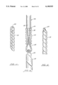
- FIG. 8 is a partial sectional view of the connection between the exposed end of the coiled tubing and a holding fixture connected to the wire line truck;
- FIG. 9 is a partial sectional view of the coiled tubing in FIG. 5 inside a lubricator of an underground well showing in particular the helical shape of the tubing after it has hit the bottom of the well and the tension in the tubing is relaxed;
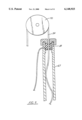
- FIG. 10 is a schematic view of a conductor extending into the coiled tubing and being unwound from a reel;
- FIGS. 11 and 12 are front and side plan views of a section of jeweler's chain useful as a weight for lowering a conductor into the tubing;
- FIG. 13 is a partial sectional view of the connection between the chain of FIGS. 11 and 12 and the conductor;
- FIG. 13A is a schematic drawing showing a minimum bend radius in the chain of FIGS. 11 and 12;
- FIG. 14 is a schematic view of the pusher tool for pushing the chain of FIGS. 11 and 12 into the tubing.
- FIGS. 15-17 are partial sectional views of the pusher tool and chain in FIG. 14, showing in particular the chain being pushed into the tubing.
- the invention relates to an improved method of inserting one or more conductors in a length of coiled tubing of the type used in conductive wire line for downhole operations.
- the method involves inserting the conductor into the coiled tubing and letting the conductor fall by gravity after the tubing is run into a well or the like.
- the invention also relates to various articles of manufacture that are useful in performing the method.
- Coiled tubing is a relatively small diameter metal conduit that is wound on a reel, which has a helical shape or residual curvature when the tubing is unwound from the reel due to an inherent memory in the metal.
- Conductive wire line is a length of coiled tubing used primarily in downhole applications, which includes one or more signal or power transmitting conductors extending through the coiled tubing.
- FIG. 1 A typical use for conductive wire line is shown in FIG. 1, where a wire line 10 is spooled or coiled on a drum or reel 12 that is mounted on a wire line truck 14.
- the wire line 10 is unwound from the drum 12 and, after passing through rollers 16 and over sheaves 18 and 20, is lowered into an underground well 22 through a lubricator 24 and a well head.
- the lubricator 24 includes a packing 28 at the upper end for forming a seal around the wire line 10 and an isolating valve 30 at the lower end for isolating the lubricator 24 from the well.
- a hydraulic pump 32 located outside the lubricator 24 pressurizes the packing 28 for effecting the seal.
- the wire line 10 is a conductive wire line formed of coiled tubing 34 and a conductor 36 that extends through the tubing 34, which is capable of transmitting signals or power.
- the conductor 36 maintains a helical shape inside the tubing 34, due to its own inherent memory, which has the advantage of supporting the conductor 36 inside the tubing 34 through the frictional interface between the outer surface of the conductor and the inner surface of the tubing, as described in U.S. Pat. No. 5,495,755. Without this support, for the lengths typically used, the weight of the conductor 36 in the well bore is greater than its break strength. Thus, the conductor 36 cannot support its own weight and would break without this frictional hold-up force.
- This inherent helical shape of the conductor is one of the problems that must be overcome if the conductor is to be inserted into the tubing in accordance with the present invention. Thus, unless the conductor is straightened, the conductor cannot fall by gravity through the coiled tubing. At the same time, however, there must be sufficient frictional contact between the outer surface of the conductor and the inner surface of the coiled tubing so that the weight of the conductor is supported by the tubing.
- the coiled tubing when a length of coiled tubing in excess of 1,000 ft., and up to and greater than 20,000 ft., is unwound from a reel and suspended in a well, the coiled tubing also has an inherent helical shape.
- the conductor in addition to being straight, must also be able to travel through the helical bends in the tubing and bends or curves caused by any irregularities in the well.
- the difficulty of inserting conductors in coiled tubing that has already been formed can be appreciated considering the relatively small inner diameter of the tubing (an outer diameter of 1/8"-1/2" minus the wall thickness) and length of the tubing (greater than 1,000 ft. and up to and greater than 20,000 ft.), and the fragile nature of the conductors (e.g., insulated electrical wire, optical fibers and the like).
- the challenge is especially daunting for inserting a wire of, for example, about 0.055" in diameter in a length of coiled tubing in excess of 1,000 ft., and up to and greater than 20,000 ft., having an inner diameter as small as 0.089", which is less than two times the diameter of the conductor 36.
- the invention described in detail below provides a solution for this extremely difficult technical problem.
- FIGS. 3 and 4 illustrate the method described in that patent, in which a conductor 36 that is spooled on a reel 42 is fed simultaneously with a metal strip 44 that is spooled on a reel 46.
- the metal strip 44 and conductor 36 are fed through a series of rollers 48, 50 and 52, which bend and roll the strip 44 into the tubing 34, with the conductor 36 inside the tubing 34.
- a spring 54 extends into the tubing 34 before the edges of the strip 44 are welded together by a welding station 56, for protecting the conductor 36 from damage.
- the final wire-in-a-tube product is then wound on a reel 58.
- the method of the present invention is an improvement over previously used methods of placing one or more conductors in coiled tubing.
- the method utilizes coiled tubing manufactured by conventional techniques without any conductors in it. Generally, this tubing is lowered in a conventional way into an underground well or other type of vertical passageway through which the tubing can extend. A conductor is then inserted into the tubing and allowed to fall by gravity through the tubing.
- a novel weight formed of an elongated segmented structure with essentially no stiffness (described in greater detail below), is connected to the leading end of the conductor for pulling the conductor straight and providing sufficient weight for gravitational forces to cause the conductor to fall to the bottom of the tubing.
- this weight is formed of a chain with interlocking links, which has sufficient flexibility to pass through bends or other irregularities in the coiled tubing caused by its inherent helical shape, by irregularities in the well casing, or by other bends formed in the manufacturing and handling of the coiled tubing.
- a chain with interlocking links is also important because it can be formed with a relatively high density to reduce the length of the weight.
- Such a chain can also be formed with a minimum bend radius for preventing the links from bunching up or jamming when the chain must be pushed into the tubing to get it started when, for example, the conductor must pass though bends of 90° or 180° before it can fall vertically into the tubing. Details of a preferred embodiment of the weight are described in greater detail below.
- a "guide means” is generally mentioned as being removably attached to the lower end of a cable to assure that the cable would not "kink” in the tubing.
- guide means no structure is described for this so-called guide means.
- An alternative method involving pumping the cable through the tubing is mentioned, which does not work because a sufficient force cannot be applied to move the cable through the tubing.
- thermocouple in an elongated wire is described as being lowered through coiled tubing extending along the outer surface of well casing
- a sinker line formed of aircraft wire with beads crimped onto the wire about 1/2" apart is described as being able to pull an elongated sensing means downward and straighten any bends in it.
- the wire although it is said to be flexible, is too stiff to travel through short radius bends because it imparts a side load on the wall of the tubing due to its inherent stiffness.
- neither of these patents constitutes an enabling disclosure of a workable way of inserting a conductor in coiled tubing that has already been placed in a substantially vertical passageway by allowing the conductor to fall freely by gravity through any small bends or other irregularities in the tubing until the conductor is fully inserted.
- FIG. 5 One way of performing the invention, which solves these problems, is shown in FIG. 5.
- the tubing 34 is spooled on a reel 60 that is mounted on a conventional wire line truck 62.
- the tubing 34 is transported to a well site or other location where a vertical passageway of suitable depth is situated.
- a second reel 100 on which conductor 36 is spooled can also be mounted on the wire line truck 62.
- a facility can be situated near a well site or the like for performing the function of the wire line truck 62.
- the coiled tubing used in conjunction with the invention is preferably formed of stainless steel or nickel alloys, but other suitable materials known in the art can be used.
- This type of coiled tubing typically has an outer diameter of 1/8"-1/2".
- a material for which the invention is particularly useful is a high-strength nickel alloy used in deep wells (greater than 16,000 ft.) called INCOLOY 825® (a trademark of the International Nickel Company), which has an outer diameter of 3/16", and a relatively thick wall of about 0.049", resulting in an inner diameter of about 0.089".
- the type of conductor that can be used in conjunction with the invention is preferably an insulated copper wire 38 formed of stranded 20 gauge nickel-plated copper wire.
- the conductor 36 has an insulation covering 40 of polyimid tape (KAPTON® a trademark of DuPont), mill spec MIL-8138/12. A secondary coating of aromatic polyimid resin is applied in a known way to seal the tape and improve durability.
- polyimid tape KAPTON® a trademark of DuPont
- a secondary coating of aromatic polyimid resin is applied in a known way to seal the tape and improve durability.
- a wide variety of other insulated electrical conductors could also be used.
- the conductor 36 could be one or more optical fibers that are capable of transmitting signals.
- Other types of conductors could also be used.
- the invention contemplates encompassing any type of signal or power transmitting conductor, or some combination thereof, that is capable of being inserted in tubing and used in down hole applications.
- the tubing 34 is run into the well in a known way, by first connecting a weight, such as known type of sinker bar 86 (see FIGS. 6 and 7), to the leading end of the tubing 34.
- a weight such as known type of sinker bar 86 (see FIGS. 6 and 7)
- the connection between the tubing 34 and the sinker bar 86 is formed by first preparing the leading end of the tubing 34 as shown in FIG. 6.
- a forming tool (not shown) of the type shown and described in co-pending patent application Ser. No. 08/666,846, filed Jun. 6, 1996, now U.S. Pat. No. 5,907,966, entitled “Roll-Formed Seat and Retainer . . . ", which application is incorporated by reference herein as though fully set forth, is used to form tapered surfaces 78, 80 and 82 in the outer surface of the tube 34.
- the tube 34 is then inserted through an opening 84 formed in a the sinker bar 86, as shown in FIG. 7.
- the sinker bar 86 includes an upper section 86A that has a chamber 88 in which a known type of fitting made by Swagelok Corporation is used to connect the sinker bar 86 to the tubing 34 and seal the leading end of the tubing 34 from fluids in the well.
- the Swagelok® fitting includes ferrules 78A, 80A and 82A for engaging the grooves 78, 80 and 82, respectively.
- the ferrules 80A and 82A are held in place between nuts 77 and 79, and a union 81.
- the ferrule 78A is held between a nut 83, a fitting 85 and a seal cap 87.
- the sinker bar 86 also includes a lower section 86B that is threaded onto the upper section 86A after the sinker bar is connected to the tubing 34 as described.
- the sinker bar also includes a fishing neck 89 for retrieving the sinker bar 86 from the well.
- the tubing 34 (including the sinker bar 86 connected its leading end), is passed over a lower sheave 64 that is connected through a cable 68 to a well head 66, and over an upper sheave 70 that is fixed to the lubricator 67.
- the lubricator 67 includes the packing, isolating valve and hydraulic pump shown in FIG. 1 for effecting a seal as discussed above, but these features have been omitted from FIG. 5 for ease of illustration.
- the tubing As the tubing is unwound from the reel 60, it has a helical shape caused by the inherent memory of the material of the tubing. Initially, the weight of the sinker bar 86 straightens the coiled tubing 34 and pulls it into the well. After gravitational forces pull the sinker bar 86 and tubing 34 a certain distance, the weight of the tubing 34 in combination with the weight of the sinker bar 86 will straighten the tubing 34 and pull it to the bottom of the well or until the sinker bar 86 is stopped by a bridge plug (not shown) set at a desired depth in the well. At this point in time, when there is no pulling force acting on the coiled tubing 34, it will have a helical shape inside the lubricator 67 and in the well as shown schematically in FIG. 9.
- the tubing 34 is then disconnected from the reel 60, and connected to the truck by using a holding fixture 91 like the one shown in FIG. 8, so that the conductor 36 can be inserted in tubing 34. Because the tubing is resting on the bottom of the well or on a bridge plug or the like in the well, the tubing 34 can be disconnected from the reel 60 and not held at the well surface. Alternatively, the tubing 34 could be held in place in the well by using known slips or the like.
- the tubing 34 is then connected to the truck in this embodiment of the invention through an arm 89 that is connected to the truck 62.
- the tubing 34 is mounted in a holding fixture 91 that is connected to the arm 89 through a bolt 93.
- a groove 95 is formed in the outer surface of the tubing 34 as shown in FIG. 8 by the same grooving tool mentioned above and described in pending U.S. patent application Ser. No. 666,846, filed Jun. 6, 1996, described above, a standard Swagelok® fitting 97 (including a ferrule 97A and backwards nut 97B) is used to connect the tubing 34 to the fixture.
- a plastic guide bushing 99 can be placed on the end of the tubing 34 for preventing the insulation or cladding on the outer surface of the conductor 36 from dragging on the sharp inside edge of the tubing 34 when it is inserted in the direction of arrow C as shown in FIG. 8.
- an elongated weight such as a chain 118 shown in FIGS. 11 and 12 is connected to the leading end 116 of the conductor 36 (see FIG. 13) for straightening the conductor 36 and pulling the conductor 36 into the tube 34.
- the elongated weight must have essentially no stiffness so that it can fall through small bends and other irregularities in the coiled tubing without imparting a side load onto the inner surface of the tubing, which would result in a frictional hold-up force.
- Such a weight can be formed of an elongated segmented structure such as a chain with interlocking links or the like.
- a beaded chain (not shown) of the type used as a pull for light fixtures could be used provided it had sufficient density to provide the needed weight.
- Segmented weights of these types have sufficient flexibility to pass through irregularities in the coiled tubing caused by its inherent helical shape or by irregularities in the well casing that cause bends in the coiled tubing.
- the weight In embodiments of the invention where the weight must be pushed initially into the coiled tubing to get it started, for example, where it must pass through bends of 90° or 180° before it can fall vertically, the weight must be formed with a minimum bend radius for preventing the links from bunching up or jamming when such irregularities are encountered.
- the minimum bend radius of a chain of the type shown in FIGS. 11 and 12 is illustrated in FIG. 13A.
- the radius line R depicts the minimum bend radius of the chain 118 when it is looped, and the ends of the chain 118 are pulled in the direction of arrows 119 until the chain locks and will not bend any further.
- a weight found to satisfy these requirements is 180 S.A. 54 jewelry chain, which is formed of brass.
- the links of this chain are different from the links in a conventional chain because they have been roll-formed into a round cross-sectional shape, to where the ends of each link are oriented at about 90° relative to each other as shown in the link 120 in FIG. 11.
- This shape substantially reduces the gaps between adjacent links and has the effect of providing a chain with a relatively high density (approximately 7 specific gravity), so that the weight has more weight per unit of length.
- a distinct advantage of this higher density chain is that a shorter length can be used to provide the required weight for initially pulling the conductor 36 into the tubing 34.
- the interlocking links 120 can be compressed for controlling the minimum bend radius of the chain 118.
- a minimum bend radius is preferably set within a range of about 1/4"-24", and more preferably at about 4".
- the chain can be purchased with the links already roll formed.
- the links can be compressed by passing the chain through a rolling mill of the type known to jewelers. A length of about 600 ft. of roll-formed brass chain (180 S.A. 54) with a minimum bend radius of about 4" (which weighed 6-7 lb.), was found satisfactory to perform the method in accordance with the invention as described.
- An advantage of the roll-formed chain 118 shown in FIGS. 11 and 12 is that it can be pushed into the coiled tubing without bunching up and jamming when it reaches a bend or other irregularity.
- the ability to push the chain initially through 90° and/or 180° bends over several pulleys and into the well can be important.
- the weight can be formed of a conventional linked chain that does not have any significant minimum bend radius.
- the interlocking links provide sufficient flexibility for allowing the chain to pass through small bends and irregularities in the tubing.
- a roll-formed and compressed chain of the type shown in FIGS. 11 and 12, where the links are twisted so that the ends of each link are oriented at 90° relative to each other has the advantage that it has about twice the density of the conventional linked chain and is therefore about twice the weight per unit length, so that only half the length must be used.
- the chain 118 with interlocking links constructed as described above, is connected to the leading end 116 of the conductor 36, as shown in FIG. 11, by using a known type of crimp connection.
- the insulation 40 is stripped from the leading end 116 exposing a short length of wire 38.
- the wire 38 is inserted into one end of a crimp connection 122.
- a loop of steel wire 124 is passed through the outside link 120 of the chain 118 and inserted into the other end of the crimp connection 122.
- a known crimping tool (not shown) is used to crimp the connection 122 onto the wire 38 and wire loop 124 for connecting the chain 118 to the wire 38.
- the chain 118 is then introduced into the tubing 34.
- an assist in such cases must be provided for the chain 118.
- An assist found to be useful is provided by a push tool 126 of the type shown in FIGS. 14-17.
- the push tool 126 frictionally engages the outer surface of the chain 118 and pushes it into the tubing 34 a sufficient distance until gravitational forces begin acting on the chain 118 and cause it to fall of its own weight.
- the push tool 126 should be able to push at least 70-100 ft. of chain into the tubing 34.
- the push tool 126 includes a pair of gripping jaws, such as those provided by a pair of VICE-GRIPS®, on which a pair of guides 128 and 130 are mounted.
- the guides 128 and 130 and guide extensions 128A and 130A (FIG. 17) form a hollow opening 132 through which the chain 118 can pass, when the guides are closed by moving the guide 128 in the direction of arrow 129 as shown in FIG. 17.
- a small electric motor 124 is connected to one of the guide extensions 130A, which drives a wheel 134 formed of rubber or other compressible elastomer. As the chain 118 passes between the drive wheel 134 and an adjacent idler wheel 135, rotation of the drive wheel 134 in the direction of the arrow 138 pushes the chain 118 in the direction of the arrows 136.
- a guide tube 140 positioned between the guide extensions 128A and 130A guides the chain 118 into the tubing 34. After the chain 118 is pushed into the tubing 34 a sufficient distance, gravity will begin operating on the chain 118 so that it falls of its own weight.
- the wire line truck 62 is moved in the direction of the arrow 74 (FIG. 5) to adjust the helical pitch of the tubing 34 for maintaining an acceptable tension in the conductor 36 below its break strength resulting from the frictional contact between the outer surface of the conductor 36 and the inner surface of the tubing 34.
- the rate of descent of the chain 118 and conductor 36 (preferably at about 200 ft./min.) is governed by a gear motor 102 connected to the reel 100, shown in FIG. 10, which controls the rate of rotation of the reel 100.
- a gear motor 102 connected to the reel 100, shown in FIG. 10, which controls the rate of rotation of the reel 100.
- the tension in the conductor e.g., the weight of the chain 118 and conductor 36 being supported in the tubing by the conductor
- the gear motor 102 regulates the speed of descent and the helical shape of the tubing 34 supports the weight of the conductor 36.
- the break strength is about 60 lb., which is less than the combined weight of the conductor 36 and the chain 118 after the conductor 36 is inserted to predetermined depth.
- the conductor 36 is able to support its own weight and will not break as it falls by gravity through the tube 34.
- a tension indicating device in the form of a scale 104 can be connected to the conductor 36 through the pulley 106 for maintaining a continuous reading of the tension load in the conductor 36, which is an indication of the weight being carried by the conductor 36. It was found that a weight of about 3-12 lbs. carried in a conductor having a break strength of about 60 lbs., provided a workable range.
- a conductive wire-line assembly is formed in a way that eliminates the need to place the conductor in coiled tubing as it is formed, which has the advantages described above.
Abstract
A method for inserting at least one conductor into an elongated length of metal coiled tubing, includes the steps of placing the coiled tubing in a substantially vertical passageway, inserting the conductor into the tubing, the leading end of the conductor including an elongated weight connected to the conductor, which weight is heavy enough to straighten the conductor enough to fall through the tubing, the weight having essentially no stiffness so that it is flexible enough to move through bends or irregularities in the tubing, allowing the conductor and weight to fall by gravity through the tubing, which has a sufficient helical pitch providing a hold-up force due to friction for preventing the conductors from breaking, until the desired length of conductor is inserted in the tubing, and removing the tubing with the conductor inside the tubing from the passageway and winding the tubing on a reel.
Description
This invention relates to downhole wire line systems and, in particular, to a method of making a wire line system that includes small-diameter tubing with one or more signal and/or power conductors extending through the tube, and articles of manufacture useful in the method.
Downhole instruments or tools for subterranean wells are lowered down a well bore and operated in a subterranean reservoir to measure, for example, formation characteristics such as bottom hole pressures and temperatures as a function of time, and to perform many other measuring, control and operational tasks in a well.
Tools of this type are typically lowered on a conductive wire line. The wire line is formed of coiled metal tubing ranging from 1/8"-1/2" in diameter, within which one or more conductors capable of transmitting a signal and/or power are located. These conductors can be insulated conductor wires, optical fibers or any other conductor capable of transmitting signals and/or power to or from a downhole location.
The use of electrical conductors within a wire line is known, and are described in U.S. Pat. Nos. 5,122,209 and 5,495,755, both of which are incorporated herein by reference. Because wire line tubing of this type comes in lengths greater than 10,000 feet, up to and longer than 20,000 feet, there has been difficulty in inserting the conductor in such lengths of tubing.
In the past, as described in U.S. Pat. No. 5,122,209, a plurality of electrical conductors have been formed within the coiled tubing by feeding a flat metal strip and the conductors simultaneously through a series of tube-forming dies, and then forming the tubing with the conductors in it by welding the elongated edges of the metal strip around the conductors. Such methods have proved useful in the past, but problems have arisen.
For example, fabrication of a wire-in-a-tube by using this method often resulted in an imperfection in the tube before the entire length of product is completed, which cannot be repaired. This adds significant cost to the manufacturing process because of the high scrap rate.
Moreover, with the advent of much deeper wells, those 16,000 feet and deeper, relatively small diameter tubing formed of a high strength material such as INCOLOY 825®, which has a relatively thick wall that is useful in such wells, cannot be formed with a conductor in it. Annealing the tubing and drawing it down in size are necessary for eliminating microscopic circumferential cracks in the weld and increasing the strength due to work hardening of the material. These steps cannot be performed with a conductor in the tubing.
Thus, there is a need for a method of making conductive wire line, especially those useful in today's deep wells, which eliminates these problems.
Problems discussed above have been solved by the invention described in detail below, which involves inserting a length of conductor into an elongated length of coiled metal tubing after the tubing is formed. The conductor can either be in the form of an insulated conductor wire, optical fibers, other conductors for conducting signals and/or power, or some combination thereof.
The invention includes the steps of inserting the tubing into a substantially vertical passageway such as a well bore, and providing an open upper end of the tubing that is accessible to an operator. The leading end of the conductor is inserted into the upper end of the tubing.
The leading end of the conductor includes an elongated weight connected to the conductor. The weight must be heavy enough to straighten the conductor so it can fall though the coiled tubing. The weight must also be flexible enough to move through small bends or other irregularities in the coiled tubing.
A weight capable of performing these functions is one that has essentially no stiffness so that it can fall freely through irregularities in the coiled tubing without imparting a side load onto the inner surface of the coiled tubing, which would prevent further downward movement. Such a weight can be formed of an elongated segmented structure such as a chain with interlocking links or the like.
In embodiments of the invention where the weight must be pushed initially into the coiled tubing, the weight must have a minimum bend radius that is great enough to prevent the segments of the weight from bunching up or jamming when a bend or other irregularity is encountered, but which has essentially no stiffness and does not impart a side load until the minimum bend radius is reached. A preferred form of such a weight is a chain with interlocking links that has been roll-formed to provide the characteristics described above.
After the conductor and weight are inserted into the coiled tubing, they are allowed to fall by gravity through the tubing at a controlled speed until the desired length of conductor is inserted in the tubing. In embodiments where, for example, the chain must travel through 90° or 180° bends before it can fall vertically in the tubing, a push tool can be used to assist the initial insertion of the chain into the tubing until there is enough weight in the tubing to allow the weight to fall by gravity and pull the conductor into the tubing.
The helical pitch of the coiled tubing is regulated so that the frictional contact between the outer surface of the conductor and the inner surface of the tubing is great enough to support the weight and conductor for preventing the conductor from breaking. After the conductor is inserted into the tubing, the conductive wire-line assembly is wound on a reel and is ready for use.
The invention can be better understood when the detailed description of preferred embodiments described below are considered in conjunction with the appended drawings, in which:
FIG. 1 is a schematic view of a conductive wire line being run into an underground well;
FIG. 2 is a sectional view of an insulated conductor inside a section of coiled metal tubing of the conductive wire line shown in FIG. 1;
FIG. 3 is a schematic view of the conventional prior art method of forming conductive wire line;
FIG. 4 is a schematic view of dies forming a strip of metal into coiled tubing in accordance with the method of FIG. 3;
FIG. 5 is a schematic view, in accordance with the present invention, of conductor being inserted into coiled tubing that has been run into an underground well from a conventional wire line truck;
FIG. 6 is a plan view of the outer surface of the downhole end of the coiled tubing in FIG. 5, with its outer surface shaped by a forming tool in accordance with the present invention so that a weight in the form of a sinker bar can be connected to the tubing for pulling the tubing into the well bore and sealing the tubing;
FIG. 7 is a partial sectional view of the weight connected to the tubing;
FIG. 8 is a partial sectional view of the connection between the exposed end of the coiled tubing and a holding fixture connected to the wire line truck;
FIG. 9 is a partial sectional view of the coiled tubing in FIG. 5 inside a lubricator of an underground well showing in particular the helical shape of the tubing after it has hit the bottom of the well and the tension in the tubing is relaxed;
FIG. 10 is a schematic view of a conductor extending into the coiled tubing and being unwound from a reel;
FIGS. 11 and 12 are front and side plan views of a section of jeweler's chain useful as a weight for lowering a conductor into the tubing;
FIG. 13 is a partial sectional view of the connection between the chain of FIGS. 11 and 12 and the conductor;
FIG. 13A is a schematic drawing showing a minimum bend radius in the chain of FIGS. 11 and 12;
FIG. 14 is a schematic view of the pusher tool for pushing the chain of FIGS. 11 and 12 into the tubing; and
FIGS. 15-17 are partial sectional views of the pusher tool and chain in FIG. 14, showing in particular the chain being pushed into the tubing.
The invention relates to an improved method of inserting one or more conductors in a length of coiled tubing of the type used in conductive wire line for downhole operations. In broad general terms, the method involves inserting the conductor into the coiled tubing and letting the conductor fall by gravity after the tubing is run into a well or the like. The invention also relates to various articles of manufacture that are useful in performing the method.
Coiled tubing is a relatively small diameter metal conduit that is wound on a reel, which has a helical shape or residual curvature when the tubing is unwound from the reel due to an inherent memory in the metal. Conductive wire line is a length of coiled tubing used primarily in downhole applications, which includes one or more signal or power transmitting conductors extending through the coiled tubing.
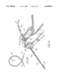
A typical use for conductive wire line is shown in FIG. 1, where a wire line 10 is spooled or coiled on a drum or reel 12 that is mounted on a wire line truck 14. The wire line 10 is unwound from the drum 12 and, after passing through rollers 16 and over sheaves 18 and 20, is lowered into an underground well 22 through a lubricator 24 and a well head. A tool 26, for example, a logging tool, is mounted on the end of the wire line 10 for performing a down hole operation.
The lubricator 24 includes a packing 28 at the upper end for forming a seal around the wire line 10 and an isolating valve 30 at the lower end for isolating the lubricator 24 from the well. A hydraulic pump 32 located outside the lubricator 24 pressurizes the packing 28 for effecting the seal.
As shown in FIG. 2, the wire line 10 is a conductive wire line formed of coiled tubing 34 and a conductor 36 that extends through the tubing 34, which is capable of transmitting signals or power. In use, the conductor 36 maintains a helical shape inside the tubing 34, due to its own inherent memory, which has the advantage of supporting the conductor 36 inside the tubing 34 through the frictional interface between the outer surface of the conductor and the inner surface of the tubing, as described in U.S. Pat. No. 5,495,755. Without this support, for the lengths typically used, the weight of the conductor 36 in the well bore is greater than its break strength. Thus, the conductor 36 cannot support its own weight and would break without this frictional hold-up force.
This inherent helical shape of the conductor is one of the problems that must be overcome if the conductor is to be inserted into the tubing in accordance with the present invention. Thus, unless the conductor is straightened, the conductor cannot fall by gravity through the coiled tubing. At the same time, however, there must be sufficient frictional contact between the outer surface of the conductor and the inner surface of the coiled tubing so that the weight of the conductor is supported by the tubing.
Moreover, when a length of coiled tubing in excess of 1,000 ft., and up to and greater than 20,000 ft., is unwound from a reel and suspended in a well, the coiled tubing also has an inherent helical shape. The conductor, in addition to being straight, must also be able to travel through the helical bends in the tubing and bends or curves caused by any irregularities in the well.
In addition to these problems, the difficulty of inserting conductors in coiled tubing that has already been formed can be appreciated considering the relatively small inner diameter of the tubing (an outer diameter of 1/8"-1/2" minus the wall thickness) and length of the tubing (greater than 1,000 ft. and up to and greater than 20,000 ft.), and the fragile nature of the conductors (e.g., insulated electrical wire, optical fibers and the like). The challenge is especially daunting for inserting a wire of, for example, about 0.055" in diameter in a length of coiled tubing in excess of 1,000 ft., and up to and greater than 20,000 ft., having an inner diameter as small as 0.089", which is less than two times the diameter of the conductor 36. The invention described in detail below provides a solution for this extremely difficult technical problem.
In the past, such wire-in-a-tube, conductive, wire-line assemblies were manufactured by forming the tubing around a conductor, as described in detail in U.S. Pat. No. 5,122,209. Briefly, by way of background, FIGS. 3 and 4 illustrate the method described in that patent, in which a conductor 36 that is spooled on a reel 42 is fed simultaneously with a metal strip 44 that is spooled on a reel 46. The metal strip 44 and conductor 36 are fed through a series of rollers 48, 50 and 52, which bend and roll the strip 44 into the tubing 34, with the conductor 36 inside the tubing 34. A spring 54 extends into the tubing 34 before the edges of the strip 44 are welded together by a welding station 56, for protecting the conductor 36 from damage. The final wire-in-a-tube product is then wound on a reel 58.
While this process has been successful in forming conductive wire line, the process is expensive and prone to a high rejection rate. Oftentimes, an imperfection occurs along the length of the tubing. Such imperfections cannot be repaired, requiring that length of tubing to be scrapped, which adds substantially to the manufacturing costs of the final product.
The method of the present invention is an improvement over previously used methods of placing one or more conductors in coiled tubing. The method utilizes coiled tubing manufactured by conventional techniques without any conductors in it. Generally, this tubing is lowered in a conventional way into an underground well or other type of vertical passageway through which the tubing can extend. A conductor is then inserted into the tubing and allowed to fall by gravity through the tubing.
A novel weight formed of an elongated segmented structure with essentially no stiffness (described in greater detail below), is connected to the leading end of the conductor for pulling the conductor straight and providing sufficient weight for gravitational forces to cause the conductor to fall to the bottom of the tubing.
Preferably, this weight is formed of a chain with interlocking links, which has sufficient flexibility to pass through bends or other irregularities in the coiled tubing caused by its inherent helical shape, by irregularities in the well casing, or by other bends formed in the manufacturing and handling of the coiled tubing. A chain with interlocking links is also important because it can be formed with a relatively high density to reduce the length of the weight. Such a chain can also be formed with a minimum bend radius for preventing the links from bunching up or jamming when the chain must be pushed into the tubing to get it started when, for example, the conductor must pass though bends of 90° or 180° before it can fall vertically into the tubing. Details of a preferred embodiment of the weight are described in greater detail below.
The use of such a chain is the first time a known workable method has been developed for inserting one or more conductors in coiled tubing that is suspended in a well or the like. Although several prior art patents suggest some of the problems that might be encountered, no workable solutions were disclosed.
For example, in U.S. Pat. No. 3,835,929, a "guide means" is generally mentioned as being removably attached to the lower end of a cable to assure that the cable would not "kink" in the tubing. However, no structure is described for this so-called guide means. An alternative method involving pumping the cable through the tubing is mentioned, which does not work because a sufficient force cannot be applied to move the cable through the tubing.
In U.S. Pat. No. 4,616,705, for a different application where a thermocouple in an elongated wire is described as being lowered through coiled tubing extending along the outer surface of well casing, a sinker line formed of aircraft wire with beads crimped onto the wire about 1/2" apart, is described as being able to pull an elongated sensing means downward and straighten any bends in it. The wire, although it is said to be flexible, is too stiff to travel through short radius bends because it imparts a side load on the wall of the tubing due to its inherent stiffness. Thus, neither of these patents constitutes an enabling disclosure of a workable way of inserting a conductor in coiled tubing that has already been placed in a substantially vertical passageway by allowing the conductor to fall freely by gravity through any small bends or other irregularities in the tubing until the conductor is fully inserted.
One way of performing the invention, which solves these problems, is shown in FIG. 5. The tubing 34 is spooled on a reel 60 that is mounted on a conventional wire line truck 62. The tubing 34 is transported to a well site or other location where a vertical passageway of suitable depth is situated. A second reel 100 on which conductor 36 is spooled can also be mounted on the wire line truck 62. Alternatively, a facility can be situated near a well site or the like for performing the function of the wire line truck 62.
The coiled tubing used in conjunction with the invention is preferably formed of stainless steel or nickel alloys, but other suitable materials known in the art can be used. This type of coiled tubing typically has an outer diameter of 1/8"-1/2". A material for which the invention is particularly useful is a high-strength nickel alloy used in deep wells (greater than 16,000 ft.) called INCOLOY 825® (a trademark of the International Nickel Company), which has an outer diameter of 3/16", and a relatively thick wall of about 0.049", resulting in an inner diameter of about 0.089".
The conventional method for placing a conductor in tubing of this type, which is described in above and shown in FIGS. 3 and 4, has been found to be unsuitable. After the tubing is initially formed, it is annealed and then drawn down to a smaller diameter for eliminating any minute circumferential cracks in the weld, refining grain structure of the material and making the tubing stronger through work hardening. These post-forming steps cannot be performed with the conductor in the tubing.
The type of conductor that can be used in conjunction with the invention is preferably an insulated copper wire 38 formed of stranded 20 gauge nickel-plated copper wire. The conductor 36 has an insulation covering 40 of polyimid tape (KAPTON® a trademark of DuPont), mill spec MIL-8138/12. A secondary coating of aromatic polyimid resin is applied in a known way to seal the tape and improve durability. However, a wide variety of other insulated electrical conductors could also be used.
Alternatively, the conductor 36 could be one or more optical fibers that are capable of transmitting signals. Other types of conductors could also be used. The invention contemplates encompassing any type of signal or power transmitting conductor, or some combination thereof, that is capable of being inserted in tubing and used in down hole applications.
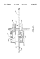
The tubing 34 is run into the well in a known way, by first connecting a weight, such as known type of sinker bar 86 (see FIGS. 6 and 7), to the leading end of the tubing 34. The connection between the tubing 34 and the sinker bar 86 is formed by first preparing the leading end of the tubing 34 as shown in FIG. 6.
A forming tool (not shown) of the type shown and described in co-pending patent application Ser. No. 08/666,846, filed Jun. 6, 1996, now U.S. Pat. No. 5,907,966, entitled "Roll-Formed Seat and Retainer . . . ", which application is incorporated by reference herein as though fully set forth, is used to form tapered surfaces 78, 80 and 82 in the outer surface of the tube 34. The tube 34 is then inserted through an opening 84 formed in a the sinker bar 86, as shown in FIG. 7. The sinker bar 86 includes an upper section 86A that has a chamber 88 in which a known type of fitting made by Swagelok Corporation is used to connect the sinker bar 86 to the tubing 34 and seal the leading end of the tubing 34 from fluids in the well.
The Swagelok® fitting includes ferrules 78A, 80A and 82A for engaging the grooves 78, 80 and 82, respectively. The ferrules 80A and 82A are held in place between nuts 77 and 79, and a union 81. The ferrule 78A is held between a nut 83, a fitting 85 and a seal cap 87. The sinker bar 86 also includes a lower section 86B that is threaded onto the upper section 86A after the sinker bar is connected to the tubing 34 as described. The sinker bar also includes a fishing neck 89 for retrieving the sinker bar 86 from the well.
As shown in FIG. 5, the tubing 34 (including the sinker bar 86 connected its leading end), is passed over a lower sheave 64 that is connected through a cable 68 to a well head 66, and over an upper sheave 70 that is fixed to the lubricator 67. The lubricator 67 includes the packing, isolating valve and hydraulic pump shown in FIG. 1 for effecting a seal as discussed above, but these features have been omitted from FIG. 5 for ease of illustration.
As the tubing is unwound from the reel 60, it has a helical shape caused by the inherent memory of the material of the tubing. Initially, the weight of the sinker bar 86 straightens the coiled tubing 34 and pulls it into the well. After gravitational forces pull the sinker bar 86 and tubing 34 a certain distance, the weight of the tubing 34 in combination with the weight of the sinker bar 86 will straighten the tubing 34 and pull it to the bottom of the well or until the sinker bar 86 is stopped by a bridge plug (not shown) set at a desired depth in the well. At this point in time, when there is no pulling force acting on the coiled tubing 34, it will have a helical shape inside the lubricator 67 and in the well as shown schematically in FIG. 9.
The tubing 34 is then disconnected from the reel 60, and connected to the truck by using a holding fixture 91 like the one shown in FIG. 8, so that the conductor 36 can be inserted in tubing 34. Because the tubing is resting on the bottom of the well or on a bridge plug or the like in the well, the tubing 34 can be disconnected from the reel 60 and not held at the well surface. Alternatively, the tubing 34 could be held in place in the well by using known slips or the like.
The tubing 34 is then connected to the truck in this embodiment of the invention through an arm 89 that is connected to the truck 62. The tubing 34 is mounted in a holding fixture 91 that is connected to the arm 89 through a bolt 93. After a groove 95 is formed in the outer surface of the tubing 34 as shown in FIG. 8 by the same grooving tool mentioned above and described in pending U.S. patent application Ser. No. 666,846, filed Jun. 6, 1996, described above, a standard Swagelok® fitting 97 (including a ferrule 97A and backwards nut 97B) is used to connect the tubing 34 to the fixture. A plastic guide bushing 99 can be placed on the end of the tubing 34 for preventing the insulation or cladding on the outer surface of the conductor 36 from dragging on the sharp inside edge of the tubing 34 when it is inserted in the direction of arrow C as shown in FIG. 8.
Because of the inherent memory of the coiled tubing 34, it maintains a helical shape in the lubricator 67 and in the well, as shown in FIG. 9, when the truck 62 is not pulling on the tubing 34 and holding it in tension. The pitch of this helical shape can be regulated, for the reasons discussed below, by moving the truck 62 back and forth as indicated by two-headed arrow 74 in FIG. 5, which movement straightens or relaxes the tubing 34.
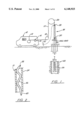
Before the conductor 36 is inserted into the coiled tubing, an elongated weight such as a chain 118 shown in FIGS. 11 and 12 is connected to the leading end 116 of the conductor 36 (see FIG. 13) for straightening the conductor 36 and pulling the conductor 36 into the tube 34. The elongated weight must have essentially no stiffness so that it can fall through small bends and other irregularities in the coiled tubing without imparting a side load onto the inner surface of the tubing, which would result in a frictional hold-up force. Such a weight can be formed of an elongated segmented structure such as a chain with interlocking links or the like. Alternatively, a beaded chain (not shown) of the type used as a pull for light fixtures could be used provided it had sufficient density to provide the needed weight. Segmented weights of these types have sufficient flexibility to pass through irregularities in the coiled tubing caused by its inherent helical shape or by irregularities in the well casing that cause bends in the coiled tubing.
In embodiments of the invention where the weight must be pushed initially into the coiled tubing to get it started, for example, where it must pass through bends of 90° or 180° before it can fall vertically, the weight must be formed with a minimum bend radius for preventing the links from bunching up or jamming when such irregularities are encountered. The minimum bend radius of a chain of the type shown in FIGS. 11 and 12 is illustrated in FIG. 13A. The radius line R depicts the minimum bend radius of the chain 118 when it is looped, and the ends of the chain 118 are pulled in the direction of arrows 119 until the chain locks and will not bend any further.
A weight found to satisfy these requirements is 180 S.A. 54 jewelry chain, which is formed of brass. As shown in FIGS. 11 and 12, the links of this chain are different from the links in a conventional chain because they have been roll-formed into a round cross-sectional shape, to where the ends of each link are oriented at about 90° relative to each other as shown in the link 120 in FIG. 11. This shape substantially reduces the gaps between adjacent links and has the effect of providing a chain with a relatively high density (approximately 7 specific gravity), so that the weight has more weight per unit of length. A distinct advantage of this higher density chain is that a shorter length can be used to provide the required weight for initially pulling the conductor 36 into the tubing 34.
The interlocking links 120 can be compressed for controlling the minimum bend radius of the chain 118. For the purposes of the invention, a minimum bend radius is preferably set within a range of about 1/4"-24", and more preferably at about 4". The chain can be purchased with the links already roll formed. The links can be compressed by passing the chain through a rolling mill of the type known to jewelers. A length of about 600 ft. of roll-formed brass chain (180 S.A. 54) with a minimum bend radius of about 4" (which weighed 6-7 lb.), was found satisfactory to perform the method in accordance with the invention as described.
An advantage of the roll-formed chain 118 shown in FIGS. 11 and 12 is that it can be pushed into the coiled tubing without bunching up and jamming when it reaches a bend or other irregularity. When the invention is performed in a well of the type shown in FIG. 1, which has a lubricator and well head, the ability to push the chain initially through 90° and/or 180° bends over several pulleys and into the well can be important.
However, if the chain can be dropped directly into the well as it is unwound from a reel, it might not have to be pushed. In such a case, the weight can be formed of a conventional linked chain that does not have any significant minimum bend radius. The interlocking links provide sufficient flexibility for allowing the chain to pass through small bends and irregularities in the tubing.
Although conventional linked chain can be used in such situations, a roll-formed and compressed chain of the type shown in FIGS. 11 and 12, where the links are twisted so that the ends of each link are oriented at 90° relative to each other, has the advantage that it has about twice the density of the conventional linked chain and is therefore about twice the weight per unit length, so that only half the length must be used.
The chain 118 with interlocking links constructed as described above, is connected to the leading end 116 of the conductor 36, as shown in FIG. 11, by using a known type of crimp connection. The insulation 40 is stripped from the leading end 116 exposing a short length of wire 38. The wire 38 is inserted into one end of a crimp connection 122. A loop of steel wire 124 is passed through the outside link 120 of the chain 118 and inserted into the other end of the crimp connection 122. A known crimping tool (not shown) is used to crimp the connection 122 onto the wire 38 and wire loop 124 for connecting the chain 118 to the wire 38.
The chain 118 is then introduced into the tubing 34. However, because the tubing 34 is not, in many cases, located directly over the well, an assist in such cases must be provided for the chain 118. An assist found to be useful is provided by a push tool 126 of the type shown in FIGS. 14-17. The push tool 126 frictionally engages the outer surface of the chain 118 and pushes it into the tubing 34 a sufficient distance until gravitational forces begin acting on the chain 118 and cause it to fall of its own weight. The push tool 126 should be able to push at least 70-100 ft. of chain into the tubing 34.
As shown in FIGS. 12-15, the push tool 126 includes a pair of gripping jaws, such as those provided by a pair of VICE-GRIPS®, on which a pair of guides 128 and 130 are mounted. The guides 128 and 130 and guide extensions 128A and 130A (FIG. 17) form a hollow opening 132 through which the chain 118 can pass, when the guides are closed by moving the guide 128 in the direction of arrow 129 as shown in FIG. 17. A small electric motor 124 is connected to one of the guide extensions 130A, which drives a wheel 134 formed of rubber or other compressible elastomer. As the chain 118 passes between the drive wheel 134 and an adjacent idler wheel 135, rotation of the drive wheel 134 in the direction of the arrow 138 pushes the chain 118 in the direction of the arrows 136.
A guide tube 140 positioned between the guide extensions 128A and 130A guides the chain 118 into the tubing 34. After the chain 118 is pushed into the tubing 34 a sufficient distance, gravity will begin operating on the chain 118 so that it falls of its own weight. The wire line truck 62 is moved in the direction of the arrow 74 (FIG. 5) to adjust the helical pitch of the tubing 34 for maintaining an acceptable tension in the conductor 36 below its break strength resulting from the frictional contact between the outer surface of the conductor 36 and the inner surface of the tubing 34.
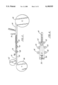
The rate of descent of the chain 118 and conductor 36 (preferably at about 200 ft./min.) is governed by a gear motor 102 connected to the reel 100, shown in FIG. 10, which controls the rate of rotation of the reel 100. Thus, if the pitch of the helix in the tubing is maintained constant, the tension in the conductor (e.g., the weight of the chain 118 and conductor 36 being supported in the tubing by the conductor) will be maintained at a constant level during the entire insertion process. The gear motor 102 regulates the speed of descent and the helical shape of the tubing 34 supports the weight of the conductor 36.
For an insulated electrical conductor wire of the type described above, the break strength is about 60 lb., which is less than the combined weight of the conductor 36 and the chain 118 after the conductor 36 is inserted to predetermined depth. However, by regulating the pitch of the tube 34, the conductor 36 is able to support its own weight and will not break as it falls by gravity through the tube 34.
As shown in FIG. 10, as the conductor is unwound from the reel 100, it moves in the direction of arrows 108, over idler pulleys 110, 112 and pulley 106, through alignment rollers 114, and into the tubing 34 which is mounted in the holding fixture 91. A tension indicating device in the form of a scale 104 can be connected to the conductor 36 through the pulley 106 for maintaining a continuous reading of the tension load in the conductor 36, which is an indication of the weight being carried by the conductor 36. It was found that a weight of about 3-12 lbs. carried in a conductor having a break strength of about 60 lbs., provided a workable range.
After the conductor 36 is completely inserted into the tubing 34, the tubing 34 is then re-connected to the reel 60 and the wire-in-a-tube is removed from the well and wound on the reel 60. Thus, a conductive wire-line assembly is formed in a way that eliminates the need to place the conductor in coiled tubing as it is formed, which has the advantages described above.
While a preferred embodiment for practicing the invention has been described, it should be understood that there are many modifications, variations and improvements that can be made that are within the spirit and scope of the invention, and that all such modifications, variations and improvements are contemplated as being covered by the appended claims.
Claims (24)
1. A method for inserting at least one conductor into an elongated length of metal coiled tubing, comprising the steps of:
(a) placing the coiled tubing in a substantially vertical passageway;
(b) inserting said conductor into the tubing, the leading end of the conductor including an elongated weight connected to the conductor, which weight is heavy enough to straighten the conductor enough to fall through the tubing, the weight having essentially no stiffness so that it is flexible enough to move through bends or irregularities in the tubing;
(c) allowing the conductor and weight to fall by gravity through the tubing, which has a sufficient helical pitch providing a hold-up force due to friction for preventing the conductor from breaking, until the desired length of conductor is inserted in the tubing; and
(d) removing the tubing with the conductor inside the tubing from the passageway and winding the tubing on a reel.
2. The method of claim 1, wherein the step of inserting a conductor includes inserting one or more insulated electrical conductor wires.
3. The method of claim 1, wherein the step of inserting a conductor includes inserting one or more optical fibers.
4. The method of claim 1, wherein the step of inserting a conductor includes inserting a combination of insulated conductor wires and optical fibers.
5. The method of claim 1, wherein the step of placing the coiled tubing includes the step of inserting at least a 1,000 ft. length of coiled tubing into a subterranean well bore.
6. The method of claim 5, wherein the step of placing the coiled tubing includes the step of inserting coiled tubing that has an outer diameter of 1/8"-1/2".
7. The method of claim 5, and further including the steps of disconnecting the tubing from a reel mounted on a truck and connecting the coiled tubing to the truck.
8. The method of claim 1, wherein the step of inserting the conductor includes the step of connecting a weight having an elongated segmented structure to the leading end of the conductor and inserting the weight into the tubing.
9. The method of claim 8, wherein the weight is formed of a chain having interconnected links.
10. The method of claim 9, wherein the chain is roll-formed and has a minimum bend radius.
11. The method of claim 10, wherein the chain has minimum bend radius of about 1/4"-24".
12. The method of claim 1, wherein the step of allowing the conductor and weight to fall by gravity includes the step of regulating the tension in the tubing so as to regulate the pitch of the helical shape of the tubing so that the frictional hold-up force between the outer surface of the conductor and the inner surface of the tubing is sufficient for the conductor to support its own weight in the tubing.
13. The method of claim 12, wherein the step of regulating the tension in the tubing includes the step of moving a truck to which the coiled tubing is connected.
14. The method of claim 1, wherein the step of allowing the conductor and weight to fall by gravity further includes the step of controlling the speed the conductor is allowed to fall.
15. The method of claim 14, wherein the step of controlling the speed includes the steps of operatively connecting a reduction gear motor to the reel from which the conductor unwinds and operating the motor at a predetermined speed.
16. The method of claim 1, wherein the step of inserting the conductor into the tubing includes the step of pushing the weight into the tubing until the weight can fall vertically through the tubing.
17. The method claim 16, wherein the step of pushing the weight includes the step of pushing the weight around at least one 90° bend in the tubing.
18. The method of claim 16, wherein the step of pushing includes the step of engaging the weight between a pair of rollers, and rotating at least one of the rollers for moving the weight through the tubing.
19. A method for inserting at least one insulated electrical conductor wire into a length of small-diameter coiled tubing extending substantially vertically in a subterranean well, said tubing having an inner diameter less than about two-times the diameter of the conductor wire, comprising the steps of:
(a) connecting a weight to the leading end of the conductor wire, said weight being formed of a segmented structure having essentially no stiffness and being heavy enough to maintain the conductor straight enough to fall by gravity through the tubing;
(b) inserting the weight into the tubing and allowing the weight and conductor to fall by gravity through the tubing; and
(c) maintaining a helical pitch in the tubing sufficient to impart a frictional hold-up force between the outer surface of the conductor and the inner surface of the tubing for preventing the conductor from breaking due to its own weight.
20. The method of claim 19, wherein the step of connecting a weight includes connecting a weight formed of a chain having interconnected links.
21. The method of claim 20, wherein the step on connecting a weight includes connecting a roll-formed chain with a minimum bend radius.
22. The method of claim 21, wherein the step of connecting a weight includes connecting a roll-formed chain with a minimum bend radius of about 1/4"-24".
23. The method of claim 19, wherein the step of maintaining a helical pitch includes the step of regulating the tension in the tubing.
24. The method of claim 23, wherein the step of regulating the tension includes the step of moving a truck to which the coiled tubing is connected.
Priority Applications (13)
| Application Number | Priority Date | Filing Date | Title |
|---|---|---|---|
| US09/249,547 US6148925A (en) | 1999-02-12 | 1999-02-12 | Method of making a conductive downhole wire line system |
| EP00908608A EP1159507B1 (en) | 1999-02-12 | 2000-02-11 | Method of making a conductive downhole wire line system |
| PCT/US2000/003627 WO2000047863A1 (en) | 1999-02-12 | 2000-02-11 | Method of making a conductive downhole wire line system |
| NZ513866A NZ513866A (en) | 1999-02-12 | 2000-02-11 | Method of making a conductive downhole wire line system |
| AT00908608T ATE308669T1 (en) | 1999-02-12 | 2000-02-11 | METHOD FOR PRODUCING A CONDUCTIVE ROPE IN THE BOREHOLE |
| DE60023661T DE60023661T2 (en) | 1999-02-12 | 2000-02-11 | METHOD FOR PRODUCING A CONDUCTIVE ROPE IN THE BORRLOCH |
| AU29916/00A AU764305B2 (en) | 1999-02-12 | 2000-02-11 | Method of making a conductive downhole wire line system |
| CA002362522A CA2362522C (en) | 1999-02-12 | 2000-02-11 | Method of making a conductive downhole wire line system |
| MXPA01008117A MXPA01008117A (en) | 1999-02-12 | 2000-02-11 | Method of making a conductive downhole wire line system. |
| NZ523181A NZ523181A (en) | 1999-02-12 | 2000-02-11 | A conductive wire line and method of making a conductive downhole wire line system |
| BR0008162-0A BR0008162A (en) | 1999-02-12 | 2000-02-11 | Method for Making an In-Line Bottom Bore Lead System |
| CN00805688.9A CN1345396A (en) | 1999-02-12 | 2000-02-11 | Method of making conductive downhole wire line system |
| EC2001004136A ECSP014136A (en) | 1999-02-12 | 2001-08-15 | METHOD FOR DEVELOPING A UNDERGROUND SYSTEM OF CONDUCTIVE WIRING |
Applications Claiming Priority (1)
| Application Number | Priority Date | Filing Date | Title |
|---|---|---|---|
| US09/249,547 US6148925A (en) | 1999-02-12 | 1999-02-12 | Method of making a conductive downhole wire line system |
Publications (1)
| Publication Number | Publication Date |
|---|---|
| US6148925A true US6148925A (en) | 2000-11-21 |
Family
ID=22943964
Family Applications (1)
| Application Number | Title | Priority Date | Filing Date |
|---|---|---|---|
| US09/249,547 Expired - Lifetime US6148925A (en) | 1999-02-12 | 1999-02-12 | Method of making a conductive downhole wire line system |
Country Status (12)
| Country | Link |
|---|---|
| US (1) | US6148925A (en) |
| EP (1) | EP1159507B1 (en) |
| CN (1) | CN1345396A (en) |
| AT (1) | ATE308669T1 (en) |
| AU (1) | AU764305B2 (en) |
| BR (1) | BR0008162A (en) |
| CA (1) | CA2362522C (en) |
| DE (1) | DE60023661T2 (en) |
| EC (1) | ECSP014136A (en) |
| MX (1) | MXPA01008117A (en) |
| NZ (1) | NZ513866A (en) |
| WO (1) | WO2000047863A1 (en) |
Cited By (21)
| Publication number | Priority date | Publication date | Assignee | Title |
|---|---|---|---|---|
| US6516891B1 (en) * | 2001-02-08 | 2003-02-11 | L. Murray Dallas | Dual string coil tubing injector assembly |
| GB2405038A (en) * | 2003-08-15 | 2005-02-16 | Schlumberger Holdings | Suspending a cable in a conduit. |
| WO2007061932A1 (en) | 2005-11-21 | 2007-05-31 | Shell Internationale Research Maatschappij B.V. | Method for monitoring fluid properties |
| US20080026623A1 (en) * | 2006-07-28 | 2008-01-31 | Quick Connectors Inc. | Electrical connector for insulated conductive wires encapsulated in protective tubing |
| US20080263848A1 (en) * | 2007-04-30 | 2008-10-30 | Mark Andreychuk | Coiled tubing with retainer for conduit |
| US20090308618A1 (en) * | 2008-06-13 | 2009-12-17 | Baker Hughes Incorporated | System and method for supporting power cable in downhole tubing |
| US20100038097A1 (en) * | 2008-02-15 | 2010-02-18 | Baker Hughes Incorporated | Coiled tubing system and method |
| US20110024103A1 (en) * | 2009-07-28 | 2011-02-03 | Storm Jr Bruce H | Method and apparatus for providing a conductor in a tubular |
| US20110168737A1 (en) * | 2010-01-08 | 2011-07-14 | Prince Castle Inc. | Rodless dispenser for extrudable materials and having a contents indicator |
| US20110168742A1 (en) * | 2010-01-08 | 2011-07-14 | Prince Castle, Inc. | Piston and piston rod for a rodless dispenser |
| US20110168741A1 (en) * | 2010-01-08 | 2011-07-14 | Prince Castle, Inc. | Rodless dispenser |
| US20110192133A1 (en) * | 2010-02-10 | 2011-08-11 | Prince Castle, Inc. | Push chain with a bias spring to prevent buckling |
| CN103452473A (en) * | 2013-08-20 | 2013-12-18 | 河北建设勘察研究院有限公司 | Method for performing small-diameter deep well construction by using full-face high-counterweight drill bit device |
| WO2014099258A1 (en) * | 2012-12-18 | 2014-06-26 | Schlumberger Canada Limited | System and method for positioning equipment for well logging |
| US9022124B2 (en) * | 2010-08-20 | 2015-05-05 | Quality Intervention As | Well intervention |
| US9194512B2 (en) | 2007-04-30 | 2015-11-24 | Mark Andreychuk | Coiled tubing with heat resistant conduit |
| US20170081925A1 (en) * | 2014-05-14 | 2017-03-23 | Aker Subsea As | Cable for an electrically submersible pump (esp) arrangement |
| WO2019172863A1 (en) * | 2018-03-05 | 2019-09-12 | Shell Oil Company | Method and system for placing an elongated element inside tubing |
| US10767419B2 (en) | 2018-07-17 | 2020-09-08 | David Wyeth SIGURDSON | Apparatus and methods for handling drill string |
| US10947817B2 (en) * | 2018-08-14 | 2021-03-16 | Robert C Kramm | Methods and systems for a tool with encapsulated heating cable within a wellbore |
| US11299937B2 (en) * | 2019-09-30 | 2022-04-12 | Halliburton Energy Services, Inc. | High pressure dual electrical collet assembly for oil and gas applications |
Families Citing this family (5)
| Publication number | Priority date | Publication date | Assignee | Title |
|---|---|---|---|---|
| US5495755A (en) * | 1993-08-02 | 1996-03-05 | Moore; Boyd B. | Slick line system with real-time surface display |
| DE102004027048B3 (en) * | 2004-05-24 | 2006-02-16 | Warschau, Katrin | Method and device for introducing geophysical measuring cables into horizontal and vertical boreholes |
| US8573313B2 (en) * | 2006-04-03 | 2013-11-05 | Schlumberger Technology Corporation | Well servicing methods and systems |
| US8549815B2 (en) * | 2008-02-29 | 2013-10-08 | National Oilwell Varco L.P. | Drilling rig masts and methods of assembly and erecting masts |
| AU2017393950B2 (en) | 2017-01-18 | 2022-11-24 | Minex Crc Ltd | Mobile coiled tubing drilling apparatus |
Citations (119)
| Publication number | Priority date | Publication date | Assignee | Title |
|---|---|---|---|---|
| US1523629A (en) * | 1921-03-28 | 1925-01-20 | Bullock Albert | Well-drilling apparatus |
| US1998826A (en) * | 1933-03-16 | 1935-04-23 | Bell Telephone Labor Inc | Electrical conducting system |
| US2018477A (en) * | 1932-08-26 | 1935-10-22 | Bell Telephone Labor Inc | Coaxial conductor system |
| US2262364A (en) * | 1940-02-15 | 1941-11-11 | Shell Dev | Cable feeding mechanism |
| US2357906A (en) * | 1942-11-02 | 1944-09-12 | Mcgraw Electric Co | Electric resistor unit |
| US2936357A (en) * | 1954-04-20 | 1960-05-10 | Thomas J Crawford | Manufacture of metal sheathed cable and the like |
| US2950454A (en) * | 1958-10-30 | 1960-08-23 | Bell Telephone Labor Inc | Helix wave guide |
| US3016503A (en) * | 1959-12-29 | 1962-01-09 | Bell Telephone Labor Inc | Helix wave guide |
| US3265803A (en) * | 1964-01-14 | 1966-08-09 | Gar Wood Ind Inc | Flexible electrical cable |
| US3285629A (en) * | 1963-12-11 | 1966-11-15 | Roy H Cullen | Methods and apparatus for mounting electrical cable in flexible drilling hose |
| US3356790A (en) * | 1966-02-18 | 1967-12-05 | Gen Cable Corp | Coaxial cable |
| US3436287A (en) * | 1965-07-02 | 1969-04-01 | Bell Telephone Labor Inc | Coaxial cable manufacturing method |
| US3443429A (en) * | 1967-01-09 | 1969-05-13 | Gulf Research Development Co | Apparatus for well treatment and measurement |
| US3614139A (en) * | 1970-06-11 | 1971-10-19 | Trojan Inc | Well casing stop collar |
| US3638732A (en) * | 1970-01-12 | 1972-02-01 | Vetco Offshore Ind Inc | Underwater wellhead electric connection apparatus for submerged electric motor driven well pumps and method of installation |
| US3737997A (en) * | 1970-07-13 | 1973-06-12 | Sensor Dynamics Inc | Continuous manufacture of shielded conductors |
| US3750263A (en) * | 1971-06-01 | 1973-08-07 | Caterpillar Tractor Co | Method for producing an assembly by friction welding |
| US3835559A (en) * | 1972-03-27 | 1974-09-17 | G Kotter | Machine for ironing trousers |
| US3897897A (en) * | 1973-03-26 | 1975-08-05 | Caterpillar Tractor Co | Method and apparatus for producing an assembly by friction welding |
| US3916685A (en) * | 1970-10-19 | 1975-11-04 | Hans J Paap | Well logging system and method using an armored coaxial cable and compensation circuit |
| US3973715A (en) * | 1973-01-09 | 1976-08-10 | Rust Ambrose G | Friction welding |
| US3996019A (en) * | 1975-04-18 | 1976-12-07 | General Electric Company | Fabrication method and fabricated article |
| US4009754A (en) * | 1975-10-09 | 1977-03-01 | General Electric Company | Electrical cable feeding and removing apparatus |
| US4038519A (en) * | 1973-11-15 | 1977-07-26 | Rhone-Poulenc S.A. | Electrically heated flexible tube having temperature measuring probe |
| US4071834A (en) * | 1975-06-12 | 1978-01-31 | Les Cables De Lyon S.A. | Helical wave guide |
| US4075820A (en) * | 1976-07-28 | 1978-02-28 | Abbott Laboratories | Spin welding apparatus |
| US4083484A (en) * | 1974-11-19 | 1978-04-11 | Kabel-Und Metallwerke Gutehoffnungshutte Ag | Process and apparatus for manufacturing flexible shielded coaxial cable |
| US4095865A (en) * | 1977-05-23 | 1978-06-20 | Shell Oil Company | Telemetering drill string with piped electrical conductor |
| US4121193A (en) * | 1977-06-23 | 1978-10-17 | Shell Oil Company | Kelly and kelly cock assembly for hard-wired telemetry system |
| US4137762A (en) * | 1977-03-02 | 1979-02-06 | Smith William D | Wireline apparatus for use in earth boreholes |
| US4220381A (en) * | 1978-04-07 | 1980-09-02 | Shell Oil Company | Drill pipe telemetering system with electrodes exposed to mud |
| US4315099A (en) * | 1979-01-12 | 1982-02-09 | Commissariat A L'energie Atomique | Flexible transmission line for a fluid and for electric signals |
| US4317003A (en) * | 1980-01-17 | 1982-02-23 | Gray Stanley J | High tensile multiple sheath cable |
| US4346256A (en) * | 1980-04-01 | 1982-08-24 | Kobe, Inc. | Conduit in supplying electrical power and pressurized fluid to a point in a subterranean well |
| US4365136A (en) * | 1981-02-23 | 1982-12-21 | Hydril Company | Zone refinement of inertia welded tubulars to impart improved corrosion resistance |
| US4368348A (en) * | 1979-12-21 | 1983-01-11 | Techno-Chemie Kessler & Co. Gmbh | Vacuum cleaner hose with an electrical conductor |
| US4372043A (en) * | 1980-11-14 | 1983-02-08 | Westinghouse Electric Corp. | Method of assembling a gas-insulated power transmission line with duter enclosure of carbon steel and aluminum |
| US4415895A (en) * | 1981-02-11 | 1983-11-15 | Dresser Industries, Inc. | Well logging data transmission system |
| US4415763A (en) * | 1980-11-14 | 1983-11-15 | Westinghouse Electric Corp. | Gas-insulated transmission line having improved outer enclosure |
| US4416494A (en) * | 1980-10-06 | 1983-11-22 | Exxon Production Research Co. | Apparatus for maintaining a coiled electric conductor in a drill string |
| US4496408A (en) * | 1981-09-04 | 1985-01-29 | Cosden Technology, Inc. | Method for producing biaxially oriented hollow articles |
| US4515211A (en) * | 1983-11-25 | 1985-05-07 | Petro Tool, Inc. | Tool cable feeding system |
| US4552432A (en) * | 1983-04-21 | 1985-11-12 | Cooper Industries, Inc. | Hybrid cable |
| US4554650A (en) * | 1982-04-02 | 1985-11-19 | The United States Of America As Represented By The Secretary Of The Navy | Oil filled towed array hose without couplings |
| US4555352A (en) * | 1983-04-08 | 1985-11-26 | Power-Aid Industries (1980) Ltd. | Lubricant additive |
| US4581926A (en) * | 1984-11-15 | 1986-04-15 | Shell Oil Company | Determination of steam quality in thermal injection wells |
| US4612984A (en) * | 1985-02-14 | 1986-09-23 | Crawford James B | Apparatus for the running and pulling of wire-line tools and the like in an oil or gas well |
| US4616705A (en) * | 1984-10-05 | 1986-10-14 | Shell Oil Company | Mini-well temperature profiling process |
| US4665281A (en) * | 1985-03-11 | 1987-05-12 | Kamis Anthony G | Flexible tubing cable system |
| US4673035A (en) * | 1986-01-06 | 1987-06-16 | Gipson Thomas C | Method and apparatus for injection of tubing into wells |
| US4681169A (en) * | 1986-07-02 | 1987-07-21 | Trw, Inc. | Apparatus and method for supplying electric power to cable suspended submergible pumps |
| US4682657A (en) * | 1985-02-14 | 1987-07-28 | Crawford James B | Method and apparatus for the running and pulling of wire-line tools and the like in an oil or gas well |
| US4710245A (en) * | 1984-12-10 | 1987-12-01 | Mannesmann Ag | Method of making tubular units for the oil and gas industry |
| US4734981A (en) * | 1986-04-16 | 1988-04-05 | Kabelmetal Electro Gmbh | Method and apparatus for manufacturing hollow tubular members |
| US4736627A (en) * | 1984-11-15 | 1988-04-12 | Shell Oil Company | Steam profile liquid/vapor separator |
| US4792802A (en) * | 1986-05-16 | 1988-12-20 | Coal Industry (Patents) Limited | Telemetry system for borehole drilling |
| US4811888A (en) * | 1987-10-26 | 1989-03-14 | Kabellmetal Electro Gmbh | Method and apparatus for manufacturing small diameter, thick walled, cable sheaths |
| US4830113A (en) * | 1987-11-20 | 1989-05-16 | Skinny Lift, Inc. | Well pumping method and apparatus |
| US4842064A (en) * | 1987-12-22 | 1989-06-27 | Otis Engineering Corporation | Well testing apparatus and methods |
| US4848480A (en) * | 1986-10-15 | 1989-07-18 | Comdisco Resources, Inc. | Method and apparatus for wire line protection in a well |
| US4942926A (en) * | 1988-01-29 | 1990-07-24 | Institut Francais Du Petrole | Device and method for carrying out operations and/or manipulations in a well |
| US4976142A (en) * | 1989-10-17 | 1990-12-11 | Baroid Technology, Inc. | Borehole pressure and temperature measurement system |
| US4998663A (en) * | 1989-12-22 | 1991-03-12 | Edison Polymer Innovation Corporation | Friction welding apparatus |
| US5071053A (en) * | 1989-05-03 | 1991-12-10 | Shell Research Limited | Method and device for joining well tubulars |
| US5072870A (en) * | 1990-02-05 | 1991-12-17 | Kabelmetal Electro Gmbh | Method and apapratus for forming metallic sheaths about optical conductor elements |
| US5080175A (en) * | 1990-03-15 | 1992-01-14 | Williams Jerry G | Use of composite rod-stiffened wireline cable for transporting well tool |
| US5088559A (en) * | 1990-11-28 | 1992-02-18 | Taliaferro William D | Method and apparatus for running wireline and reeled tubing into a wellbore and stuffing box used in connection therewith |
| US5094340A (en) * | 1990-11-16 | 1992-03-10 | Otis Engineering Corporation | Gripper blocks for reeled tubing injectors |
| US5119089A (en) * | 1991-02-20 | 1992-06-02 | Hanna Khalil | Downhole seismic sensor cable |
| US5118226A (en) * | 1990-05-18 | 1992-06-02 | Toa Kikai Kogyo Co., Ltd. | Method for passing a cable, a wire or an optical fiber through a passage |
| US5122209A (en) * | 1989-12-18 | 1992-06-16 | Shell Oil Company | Temperature compensated wire-conducting tube and method of manufacture |
| US5121872A (en) * | 1991-08-30 | 1992-06-16 | Hydrolex, Inc. | Method and apparatus for installing electrical logging cable inside coiled tubing |
| US5121628A (en) * | 1990-10-09 | 1992-06-16 | Merkl Arthur W | Ultrasonic detection system |
| US5140318A (en) * | 1991-04-12 | 1992-08-18 | Conoco Inc. | Data transmission system for downhole logging tools |
| US5140319A (en) * | 1990-06-15 | 1992-08-18 | Westech Geophysical, Inc. | Video logging system having remote power source |
| US5145007A (en) * | 1991-03-28 | 1992-09-08 | Camco International Inc. | Well operated electrical pump suspension method and system |
| US5146982A (en) * | 1991-03-28 | 1992-09-15 | Camco International Inc. | Coil tubing electrical cable for well pumping system |
| US5163321A (en) * | 1989-10-17 | 1992-11-17 | Baroid Technology, Inc. | Borehole pressure and temperature measurement system |
| US5176207A (en) * | 1989-08-30 | 1993-01-05 | Science & Engineering, Inc. | Underground instrumentation emplacement system |
| US5180014A (en) * | 1991-02-14 | 1993-01-19 | Otis Engineering Corporation | System for deploying submersible pump using reeled tubing |
| US5184682A (en) * | 1988-05-20 | 1993-02-09 | Jacques Delacour | Device allowing measurements or interventions to be carried out in a well, method using the device and applications of the device |
| US5186048A (en) * | 1989-09-14 | 1993-02-16 | Schlumberger Technology Corporation | Method and apparatus for logging a well below a downhole pump |
| US5191173A (en) * | 1991-04-22 | 1993-03-02 | Otis Engineering Corporation | Electrical cable in reeled tubing |
| US5234058A (en) * | 1990-03-15 | 1993-08-10 | Conoco Inc. | Composite rod-stiffened spoolable cable with conductors |
| US5269377A (en) * | 1992-11-25 | 1993-12-14 | Baker Hughes Incorporated | Coil tubing supported electrical submersible pump |
| US5275038A (en) * | 1991-05-20 | 1994-01-04 | Otis Engineering Corporation | Downhole reeled tubing inspection system with fiberoptic cable |
| US5289882A (en) * | 1991-02-06 | 1994-03-01 | Boyd B. Moore | Sealed electrical conductor method and arrangement for use with a well bore in hazardous areas |
| US5291942A (en) * | 1993-05-24 | 1994-03-08 | Gas Research Institute | Multiple stage sorption and desorption process and apparatus |
| US5294923A (en) * | 1992-01-31 | 1994-03-15 | Baker Hughes Incorporated | Method and apparatus for relaying downhole data to the surface |
| US5329811A (en) * | 1993-02-04 | 1994-07-19 | Halliburton Company | Downhole fluid property measurement tool |
| US5348097A (en) * | 1991-11-13 | 1994-09-20 | Institut Francais Du Petrole | Device for carrying out measuring and servicing operations in a well bore, comprising tubing having a rod centered therein, process for assembling the device and use of the device in an oil well |
| US5377747A (en) * | 1993-08-11 | 1995-01-03 | Biw Connector Systems, Inc. | Environmentally safe wellhead |
| US5380977A (en) * | 1989-12-05 | 1995-01-10 | Nkk Corporation | Apparatus for manufacturing metal tube covered optical fiber cable and method therefor |
| US5394943A (en) * | 1993-11-05 | 1995-03-07 | Harrington; Donald R. | Subsurface shutdown safety valve and arrangement system |
| US5410106A (en) * | 1991-04-26 | 1995-04-25 | Fujikura Ltd. | Electric feed cable for oil well pump |
| US5429194A (en) * | 1994-04-29 | 1995-07-04 | Western Atlas International, Inc. | Method for inserting a wireline inside coiled tubing |
| US5435395A (en) * | 1994-03-22 | 1995-07-25 | Halliburton Company | Method for running downhole tools and devices with coiled tubing |
| US5457988A (en) * | 1993-10-28 | 1995-10-17 | Panex Corporation | Side pocket mandrel pressure measuring system |
| US5485745A (en) * | 1991-05-20 | 1996-01-23 | Halliburton Company | Modular downhole inspection system for coiled tubing |
| US5495755A (en) | 1993-08-02 | 1996-03-05 | Moore; Boyd B. | Slick line system with real-time surface display |
| US5503370A (en) | 1994-07-08 | 1996-04-02 | Ctes, Inc. | Method and apparatus for the injection of cable into coiled tubing |
| US5542472A (en) | 1993-10-25 | 1996-08-06 | Camco International, Inc. | Metal coiled tubing with signal transmitting passageway |
| US5569392A (en) | 1993-12-27 | 1996-10-29 | Kabushiki Kaisha Toshiba | Method and apparatus for repairing defect on plane surface of phase shift mask |
| US5573225A (en) | 1994-05-06 | 1996-11-12 | Dowell, A Division Of Schlumberger Technology Corporation | Means for placing cable within coiled tubing |
| US5582748A (en) | 1995-02-14 | 1996-12-10 | Nkk Corporation | Method of manufacturing optical fiber cable covered with metal pipe, and apparatus for manufacturing this optical fiber cable |
| US5599004A (en) | 1994-07-08 | 1997-02-04 | Coiled Tubing Engineering Services, Inc. | Apparatus for the injection of cable into coiled tubing |
| US5661402A (en) | 1994-03-31 | 1997-08-26 | Halliburton Energy Services, Inc. | Sealed modular downhole antenna |
| US5767411A (en) | 1996-12-31 | 1998-06-16 | Cidra Corporation | Apparatus for enhancing strain in intrinsic fiber optic sensors and packaging same for harsh environments |
| US5778978A (en) | 1996-08-06 | 1998-07-14 | Pipe Recovery Services, L.L.P. | Exterior wireline cable adapter sub |
| US5809916A (en) | 1995-04-06 | 1998-09-22 | Strand; Harald | Inserting device for coiled tubing |
| US5821452A (en) | 1997-03-14 | 1998-10-13 | Baker Hughes Incorporated | Coiled tubing supported electrical cable having clamped elastomer supports |
| US5826654A (en) | 1996-01-26 | 1998-10-27 | Schlumberger Technology Corp. | Measuring recording and retrieving data on coiled tubing system |
| US5828003A (en) | 1996-01-29 | 1998-10-27 | Dowell -- A Division of Schlumberger Technology Corporation | Composite coiled tubing apparatus and methods |
| US5835929A (en) | 1996-05-20 | 1998-11-10 | Integrated Device Technology, Inc. | Method and apparatus for sub cache line access and storage allowing access to sub cache lines before completion of a line fill |
| US5848642A (en) | 1994-09-16 | 1998-12-15 | Transocean Asa | Device for coil tubing operations |
| US5855062A (en) | 1996-07-31 | 1999-01-05 | Kendall, Jr.; Clarence E. | Method and apparatus for manufacturing an insulated conductor in metal tubing |
| US5934537A (en) | 1997-01-22 | 1999-08-10 | Miller; James Edwin | Device for pushing or pulling using gripping |
| US5954136A (en) | 1997-08-25 | 1999-09-21 | Camco International, Inc. | Method of suspending an ESP within a wellbore |
| EP0791719B1 (en) | 1996-02-22 | 2000-01-05 | Halliburton Energy Services, Inc. | Gripper block for coiled tubing injectors |
Family Cites Families (3)
| Publication number | Priority date | Publication date | Assignee | Title |
|---|---|---|---|---|
| US579213A (en) * | 1896-01-31 | 1897-03-23 | Herbert | |
| DE2519791C2 (en) * | 1975-05-03 | 1977-04-07 | Alexander Perl | FULL, ALMOST SOLID-LOOKING JEWELRY LINK CHAIN |
| US4454999A (en) * | 1981-04-20 | 1984-06-19 | Woodruff Harold F | Cable dispensing device and method |
-
1999
- 1999-02-12 US US09/249,547 patent/US6148925A/en not_active Expired - Lifetime
-
2000
- 2000-02-11 MX MXPA01008117A patent/MXPA01008117A/en active IP Right Grant
- 2000-02-11 CN CN00805688.9A patent/CN1345396A/en active Pending
- 2000-02-11 WO PCT/US2000/003627 patent/WO2000047863A1/en active IP Right Grant
- 2000-02-11 AU AU29916/00A patent/AU764305B2/en not_active Ceased
- 2000-02-11 NZ NZ513866A patent/NZ513866A/en unknown
- 2000-02-11 EP EP00908608A patent/EP1159507B1/en not_active Expired - Lifetime
- 2000-02-11 CA CA002362522A patent/CA2362522C/en not_active Expired - Fee Related
- 2000-02-11 AT AT00908608T patent/ATE308669T1/en not_active IP Right Cessation
- 2000-02-11 BR BR0008162-0A patent/BR0008162A/en not_active Application Discontinuation
- 2000-02-11 DE DE60023661T patent/DE60023661T2/en not_active Expired - Lifetime
-
2001
- 2001-08-15 EC EC2001004136A patent/ECSP014136A/en unknown
Patent Citations (122)
| Publication number | Priority date | Publication date | Assignee | Title |
|---|---|---|---|---|
| US1523629A (en) * | 1921-03-28 | 1925-01-20 | Bullock Albert | Well-drilling apparatus |
| US2018477A (en) * | 1932-08-26 | 1935-10-22 | Bell Telephone Labor Inc | Coaxial conductor system |
| US1998826A (en) * | 1933-03-16 | 1935-04-23 | Bell Telephone Labor Inc | Electrical conducting system |
| US2262364A (en) * | 1940-02-15 | 1941-11-11 | Shell Dev | Cable feeding mechanism |
| US2357906A (en) * | 1942-11-02 | 1944-09-12 | Mcgraw Electric Co | Electric resistor unit |
| US2936357A (en) * | 1954-04-20 | 1960-05-10 | Thomas J Crawford | Manufacture of metal sheathed cable and the like |
| US2950454A (en) * | 1958-10-30 | 1960-08-23 | Bell Telephone Labor Inc | Helix wave guide |
| US3016503A (en) * | 1959-12-29 | 1962-01-09 | Bell Telephone Labor Inc | Helix wave guide |
| US3285629A (en) * | 1963-12-11 | 1966-11-15 | Roy H Cullen | Methods and apparatus for mounting electrical cable in flexible drilling hose |
| US3265803A (en) * | 1964-01-14 | 1966-08-09 | Gar Wood Ind Inc | Flexible electrical cable |
| US3436287A (en) * | 1965-07-02 | 1969-04-01 | Bell Telephone Labor Inc | Coaxial cable manufacturing method |
| US3356790A (en) * | 1966-02-18 | 1967-12-05 | Gen Cable Corp | Coaxial cable |
| US3443429A (en) * | 1967-01-09 | 1969-05-13 | Gulf Research Development Co | Apparatus for well treatment and measurement |
| US3638732A (en) * | 1970-01-12 | 1972-02-01 | Vetco Offshore Ind Inc | Underwater wellhead electric connection apparatus for submerged electric motor driven well pumps and method of installation |
| US3614139A (en) * | 1970-06-11 | 1971-10-19 | Trojan Inc | Well casing stop collar |
| US3737997A (en) * | 1970-07-13 | 1973-06-12 | Sensor Dynamics Inc | Continuous manufacture of shielded conductors |
| US3916685A (en) * | 1970-10-19 | 1975-11-04 | Hans J Paap | Well logging system and method using an armored coaxial cable and compensation circuit |
| US3750263A (en) * | 1971-06-01 | 1973-08-07 | Caterpillar Tractor Co | Method for producing an assembly by friction welding |
| US3835559A (en) * | 1972-03-27 | 1974-09-17 | G Kotter | Machine for ironing trousers |
| US3973715A (en) * | 1973-01-09 | 1976-08-10 | Rust Ambrose G | Friction welding |
| US3897897A (en) * | 1973-03-26 | 1975-08-05 | Caterpillar Tractor Co | Method and apparatus for producing an assembly by friction welding |
| US4038519A (en) * | 1973-11-15 | 1977-07-26 | Rhone-Poulenc S.A. | Electrically heated flexible tube having temperature measuring probe |
| US4083484A (en) * | 1974-11-19 | 1978-04-11 | Kabel-Und Metallwerke Gutehoffnungshutte Ag | Process and apparatus for manufacturing flexible shielded coaxial cable |
| US3996019A (en) * | 1975-04-18 | 1976-12-07 | General Electric Company | Fabrication method and fabricated article |
| US4071834A (en) * | 1975-06-12 | 1978-01-31 | Les Cables De Lyon S.A. | Helical wave guide |
| US4009754A (en) * | 1975-10-09 | 1977-03-01 | General Electric Company | Electrical cable feeding and removing apparatus |
| US4075820A (en) * | 1976-07-28 | 1978-02-28 | Abbott Laboratories | Spin welding apparatus |
| US4137762A (en) * | 1977-03-02 | 1979-02-06 | Smith William D | Wireline apparatus for use in earth boreholes |
| US4095865A (en) * | 1977-05-23 | 1978-06-20 | Shell Oil Company | Telemetering drill string with piped electrical conductor |
| US4121193A (en) * | 1977-06-23 | 1978-10-17 | Shell Oil Company | Kelly and kelly cock assembly for hard-wired telemetry system |
| US4220381A (en) * | 1978-04-07 | 1980-09-02 | Shell Oil Company | Drill pipe telemetering system with electrodes exposed to mud |
| US4315099A (en) * | 1979-01-12 | 1982-02-09 | Commissariat A L'energie Atomique | Flexible transmission line for a fluid and for electric signals |
| US4368348A (en) * | 1979-12-21 | 1983-01-11 | Techno-Chemie Kessler & Co. Gmbh | Vacuum cleaner hose with an electrical conductor |
| US4317003A (en) * | 1980-01-17 | 1982-02-23 | Gray Stanley J | High tensile multiple sheath cable |
| US4346256A (en) * | 1980-04-01 | 1982-08-24 | Kobe, Inc. | Conduit in supplying electrical power and pressurized fluid to a point in a subterranean well |
| US4416494A (en) * | 1980-10-06 | 1983-11-22 | Exxon Production Research Co. | Apparatus for maintaining a coiled electric conductor in a drill string |
| US4372043A (en) * | 1980-11-14 | 1983-02-08 | Westinghouse Electric Corp. | Method of assembling a gas-insulated power transmission line with duter enclosure of carbon steel and aluminum |
| US4415763A (en) * | 1980-11-14 | 1983-11-15 | Westinghouse Electric Corp. | Gas-insulated transmission line having improved outer enclosure |
| US4415895A (en) * | 1981-02-11 | 1983-11-15 | Dresser Industries, Inc. | Well logging data transmission system |
| US4365136A (en) * | 1981-02-23 | 1982-12-21 | Hydril Company | Zone refinement of inertia welded tubulars to impart improved corrosion resistance |
| US4496408A (en) * | 1981-09-04 | 1985-01-29 | Cosden Technology, Inc. | Method for producing biaxially oriented hollow articles |
| US4554650A (en) * | 1982-04-02 | 1985-11-19 | The United States Of America As Represented By The Secretary Of The Navy | Oil filled towed array hose without couplings |
| US4555352A (en) * | 1983-04-08 | 1985-11-26 | Power-Aid Industries (1980) Ltd. | Lubricant additive |
| US4552432A (en) * | 1983-04-21 | 1985-11-12 | Cooper Industries, Inc. | Hybrid cable |
| US4515211A (en) * | 1983-11-25 | 1985-05-07 | Petro Tool, Inc. | Tool cable feeding system |
| US4616705A (en) * | 1984-10-05 | 1986-10-14 | Shell Oil Company | Mini-well temperature profiling process |
| US4581926A (en) * | 1984-11-15 | 1986-04-15 | Shell Oil Company | Determination of steam quality in thermal injection wells |
| US4736627A (en) * | 1984-11-15 | 1988-04-12 | Shell Oil Company | Steam profile liquid/vapor separator |
| US4710245A (en) * | 1984-12-10 | 1987-12-01 | Mannesmann Ag | Method of making tubular units for the oil and gas industry |
| US4612984A (en) * | 1985-02-14 | 1986-09-23 | Crawford James B | Apparatus for the running and pulling of wire-line tools and the like in an oil or gas well |
| US4682657A (en) * | 1985-02-14 | 1987-07-28 | Crawford James B | Method and apparatus for the running and pulling of wire-line tools and the like in an oil or gas well |
| US4665281A (en) * | 1985-03-11 | 1987-05-12 | Kamis Anthony G | Flexible tubing cable system |
| US4673035B1 (en) * | 1986-01-06 | 1999-08-10 | Plains Energy Services Ltd | Method and apparatus for injection of tubing into wells |
| US4673035A (en) * | 1986-01-06 | 1987-06-16 | Gipson Thomas C | Method and apparatus for injection of tubing into wells |
| US4734981A (en) * | 1986-04-16 | 1988-04-05 | Kabelmetal Electro Gmbh | Method and apparatus for manufacturing hollow tubular members |
| US4792802A (en) * | 1986-05-16 | 1988-12-20 | Coal Industry (Patents) Limited | Telemetry system for borehole drilling |
| US4681169A (en) * | 1986-07-02 | 1987-07-21 | Trw, Inc. | Apparatus and method for supplying electric power to cable suspended submergible pumps |
| US4848480A (en) * | 1986-10-15 | 1989-07-18 | Comdisco Resources, Inc. | Method and apparatus for wire line protection in a well |
| US4811888A (en) * | 1987-10-26 | 1989-03-14 | Kabellmetal Electro Gmbh | Method and apparatus for manufacturing small diameter, thick walled, cable sheaths |
| US4830113A (en) * | 1987-11-20 | 1989-05-16 | Skinny Lift, Inc. | Well pumping method and apparatus |
| US4842064A (en) * | 1987-12-22 | 1989-06-27 | Otis Engineering Corporation | Well testing apparatus and methods |
| US4942926A (en) * | 1988-01-29 | 1990-07-24 | Institut Francais Du Petrole | Device and method for carrying out operations and/or manipulations in a well |
| US5184682A (en) * | 1988-05-20 | 1993-02-09 | Jacques Delacour | Device allowing measurements or interventions to be carried out in a well, method using the device and applications of the device |
| US5071053A (en) * | 1989-05-03 | 1991-12-10 | Shell Research Limited | Method and device for joining well tubulars |
| US5176207A (en) * | 1989-08-30 | 1993-01-05 | Science & Engineering, Inc. | Underground instrumentation emplacement system |
| US5186048A (en) * | 1989-09-14 | 1993-02-16 | Schlumberger Technology Corporation | Method and apparatus for logging a well below a downhole pump |
| US5163321A (en) * | 1989-10-17 | 1992-11-17 | Baroid Technology, Inc. | Borehole pressure and temperature measurement system |
| US4976142A (en) * | 1989-10-17 | 1990-12-11 | Baroid Technology, Inc. | Borehole pressure and temperature measurement system |
| US5380977A (en) * | 1989-12-05 | 1995-01-10 | Nkk Corporation | Apparatus for manufacturing metal tube covered optical fiber cable and method therefor |
| US5122209A (en) * | 1989-12-18 | 1992-06-16 | Shell Oil Company | Temperature compensated wire-conducting tube and method of manufacture |
| US4998663A (en) * | 1989-12-22 | 1991-03-12 | Edison Polymer Innovation Corporation | Friction welding apparatus |
| US5072870A (en) * | 1990-02-05 | 1991-12-17 | Kabelmetal Electro Gmbh | Method and apapratus for forming metallic sheaths about optical conductor elements |
| US5080175A (en) * | 1990-03-15 | 1992-01-14 | Williams Jerry G | Use of composite rod-stiffened wireline cable for transporting well tool |
| US5234058A (en) * | 1990-03-15 | 1993-08-10 | Conoco Inc. | Composite rod-stiffened spoolable cable with conductors |
| US5118226A (en) * | 1990-05-18 | 1992-06-02 | Toa Kikai Kogyo Co., Ltd. | Method for passing a cable, a wire or an optical fiber through a passage |
| US5355128A (en) * | 1990-06-15 | 1994-10-11 | Westech Geophysical, Inc. | Video logging system having an optical communications link |
| US5140319A (en) * | 1990-06-15 | 1992-08-18 | Westech Geophysical, Inc. | Video logging system having remote power source |
| US5121628A (en) * | 1990-10-09 | 1992-06-16 | Merkl Arthur W | Ultrasonic detection system |
| US5094340A (en) * | 1990-11-16 | 1992-03-10 | Otis Engineering Corporation | Gripper blocks for reeled tubing injectors |
| US5088559A (en) * | 1990-11-28 | 1992-02-18 | Taliaferro William D | Method and apparatus for running wireline and reeled tubing into a wellbore and stuffing box used in connection therewith |
| US5289882A (en) * | 1991-02-06 | 1994-03-01 | Boyd B. Moore | Sealed electrical conductor method and arrangement for use with a well bore in hazardous areas |
| US5180014A (en) * | 1991-02-14 | 1993-01-19 | Otis Engineering Corporation | System for deploying submersible pump using reeled tubing |
| US5119089A (en) * | 1991-02-20 | 1992-06-02 | Hanna Khalil | Downhole seismic sensor cable |
| US5146982A (en) * | 1991-03-28 | 1992-09-15 | Camco International Inc. | Coil tubing electrical cable for well pumping system |
| US5145007A (en) * | 1991-03-28 | 1992-09-08 | Camco International Inc. | Well operated electrical pump suspension method and system |
| US5140318A (en) * | 1991-04-12 | 1992-08-18 | Conoco Inc. | Data transmission system for downhole logging tools |
| US5191173A (en) * | 1991-04-22 | 1993-03-02 | Otis Engineering Corporation | Electrical cable in reeled tubing |
| US5410106A (en) * | 1991-04-26 | 1995-04-25 | Fujikura Ltd. | Electric feed cable for oil well pump |
| US5275038A (en) * | 1991-05-20 | 1994-01-04 | Otis Engineering Corporation | Downhole reeled tubing inspection system with fiberoptic cable |
| US5485745A (en) * | 1991-05-20 | 1996-01-23 | Halliburton Company | Modular downhole inspection system for coiled tubing |
| US5121872A (en) * | 1991-08-30 | 1992-06-16 | Hydrolex, Inc. | Method and apparatus for installing electrical logging cable inside coiled tubing |
| US5348097A (en) * | 1991-11-13 | 1994-09-20 | Institut Francais Du Petrole | Device for carrying out measuring and servicing operations in a well bore, comprising tubing having a rod centered therein, process for assembling the device and use of the device in an oil well |
| US5294923A (en) * | 1992-01-31 | 1994-03-15 | Baker Hughes Incorporated | Method and apparatus for relaying downhole data to the surface |
| US5269377A (en) * | 1992-11-25 | 1993-12-14 | Baker Hughes Incorporated | Coil tubing supported electrical submersible pump |
| US5329811A (en) * | 1993-02-04 | 1994-07-19 | Halliburton Company | Downhole fluid property measurement tool |
| US5291942A (en) * | 1993-05-24 | 1994-03-08 | Gas Research Institute | Multiple stage sorption and desorption process and apparatus |
| US5495755A (en) | 1993-08-02 | 1996-03-05 | Moore; Boyd B. | Slick line system with real-time surface display |
| US5377747A (en) * | 1993-08-11 | 1995-01-03 | Biw Connector Systems, Inc. | Environmentally safe wellhead |
| US5542472A (en) | 1993-10-25 | 1996-08-06 | Camco International, Inc. | Metal coiled tubing with signal transmitting passageway |
| US5457988A (en) * | 1993-10-28 | 1995-10-17 | Panex Corporation | Side pocket mandrel pressure measuring system |
| US5394943A (en) * | 1993-11-05 | 1995-03-07 | Harrington; Donald R. | Subsurface shutdown safety valve and arrangement system |
| US5569392A (en) | 1993-12-27 | 1996-10-29 | Kabushiki Kaisha Toshiba | Method and apparatus for repairing defect on plane surface of phase shift mask |
| US5435395A (en) * | 1994-03-22 | 1995-07-25 | Halliburton Company | Method for running downhole tools and devices with coiled tubing |
| US5661402A (en) | 1994-03-31 | 1997-08-26 | Halliburton Energy Services, Inc. | Sealed modular downhole antenna |
| US5429194A (en) * | 1994-04-29 | 1995-07-04 | Western Atlas International, Inc. | Method for inserting a wireline inside coiled tubing |
| US5573225A (en) | 1994-05-06 | 1996-11-12 | Dowell, A Division Of Schlumberger Technology Corporation | Means for placing cable within coiled tubing |
| US5699996A (en) | 1994-05-06 | 1997-12-23 | Schlumberger Technology Corporation | Method for placing cable within coiled tubing |
| US5599004A (en) | 1994-07-08 | 1997-02-04 | Coiled Tubing Engineering Services, Inc. | Apparatus for the injection of cable into coiled tubing |
| US5503370A (en) | 1994-07-08 | 1996-04-02 | Ctes, Inc. | Method and apparatus for the injection of cable into coiled tubing |
| US5848642A (en) | 1994-09-16 | 1998-12-15 | Transocean Asa | Device for coil tubing operations |
| US5582748A (en) | 1995-02-14 | 1996-12-10 | Nkk Corporation | Method of manufacturing optical fiber cable covered with metal pipe, and apparatus for manufacturing this optical fiber cable |
| US5809916A (en) | 1995-04-06 | 1998-09-22 | Strand; Harald | Inserting device for coiled tubing |
| US5826654A (en) | 1996-01-26 | 1998-10-27 | Schlumberger Technology Corp. | Measuring recording and retrieving data on coiled tubing system |
| US5828003A (en) | 1996-01-29 | 1998-10-27 | Dowell -- A Division of Schlumberger Technology Corporation | Composite coiled tubing apparatus and methods |
| EP0791719B1 (en) | 1996-02-22 | 2000-01-05 | Halliburton Energy Services, Inc. | Gripper block for coiled tubing injectors |
| US5835929A (en) | 1996-05-20 | 1998-11-10 | Integrated Device Technology, Inc. | Method and apparatus for sub cache line access and storage allowing access to sub cache lines before completion of a line fill |
| US5855062A (en) | 1996-07-31 | 1999-01-05 | Kendall, Jr.; Clarence E. | Method and apparatus for manufacturing an insulated conductor in metal tubing |
| US5778978A (en) | 1996-08-06 | 1998-07-14 | Pipe Recovery Services, L.L.P. | Exterior wireline cable adapter sub |
| US5767411A (en) | 1996-12-31 | 1998-06-16 | Cidra Corporation | Apparatus for enhancing strain in intrinsic fiber optic sensors and packaging same for harsh environments |
| US5934537A (en) | 1997-01-22 | 1999-08-10 | Miller; James Edwin | Device for pushing or pulling using gripping |
| US5821452A (en) | 1997-03-14 | 1998-10-13 | Baker Hughes Incorporated | Coiled tubing supported electrical cable having clamped elastomer supports |
| US5954136A (en) | 1997-08-25 | 1999-09-21 | Camco International, Inc. | Method of suspending an ESP within a wellbore |
Non-Patent Citations (2)
| Title |
|---|
| S.N. 666,846; Moore; Rolled Formed Seat and Retainer for a Fluid Tight Ferrule Seal on a Rigid Metal Tube Which is Harder Than the Ferrule, Method and Aparatus; Filed: Jun. 19, 1996. * |
| S.N. 666,846; Moore; Rolled-Formed Seat and Retainer for a Fluid-Tight Ferrule Seal on a Rigid Metal Tube Which is Harder Than the Ferrule, Method and Aparatus; Filed: Jun. 19, 1996. |
Cited By (34)
| Publication number | Priority date | Publication date | Assignee | Title |
|---|---|---|---|---|
| US6516891B1 (en) * | 2001-02-08 | 2003-02-11 | L. Murray Dallas | Dual string coil tubing injector assembly |
| GB2405038A (en) * | 2003-08-15 | 2005-02-16 | Schlumberger Holdings | Suspending a cable in a conduit. |
| US20050045343A1 (en) * | 2003-08-15 | 2005-03-03 | Schlumberger Technology Corporation | A Conduit Having a Cable Therein |
| GB2405038B (en) * | 2003-08-15 | 2006-08-09 | Schlumberger Holdings | A conduit having a cable therein |
| AU2006318645B2 (en) * | 2005-11-21 | 2010-05-27 | Shell Internationale Research Maatschappij B.V. | Method for monitoring fluid properties |
| WO2007061932A1 (en) | 2005-11-21 | 2007-05-31 | Shell Internationale Research Maatschappij B.V. | Method for monitoring fluid properties |
| US20070125163A1 (en) * | 2005-11-21 | 2007-06-07 | Dria Dennis E | Method for monitoring fluid properties |
| US7409858B2 (en) | 2005-11-21 | 2008-08-12 | Shell Oil Company | Method for monitoring fluid properties |
| US20080026623A1 (en) * | 2006-07-28 | 2008-01-31 | Quick Connectors Inc. | Electrical connector for insulated conductive wires encapsulated in protective tubing |
| US7980873B2 (en) | 2006-07-28 | 2011-07-19 | Emerson Tod D | Electrical connector for insulated conductive wires encapsulated in protective tubing |
| US20080263848A1 (en) * | 2007-04-30 | 2008-10-30 | Mark Andreychuk | Coiled tubing with retainer for conduit |
| US9194512B2 (en) | 2007-04-30 | 2015-11-24 | Mark Andreychuk | Coiled tubing with heat resistant conduit |
| US8567657B2 (en) | 2007-04-30 | 2013-10-29 | Mtj Consulting Services Inc. | Coiled tubing with retainer for conduit |
| US20100038097A1 (en) * | 2008-02-15 | 2010-02-18 | Baker Hughes Incorporated | Coiled tubing system and method |
| US7849928B2 (en) * | 2008-06-13 | 2010-12-14 | Baker Hughes Incorporated | System and method for supporting power cable in downhole tubing |
| US20090308618A1 (en) * | 2008-06-13 | 2009-12-17 | Baker Hughes Incorporated | System and method for supporting power cable in downhole tubing |
| US20110024103A1 (en) * | 2009-07-28 | 2011-02-03 | Storm Jr Bruce H | Method and apparatus for providing a conductor in a tubular |
| US20110168741A1 (en) * | 2010-01-08 | 2011-07-14 | Prince Castle, Inc. | Rodless dispenser |
| US8376193B2 (en) | 2010-01-08 | 2013-02-19 | Prince Castle, LLC | Rodless dispenser |
| US8381950B2 (en) | 2010-01-08 | 2013-02-26 | Prince Castle, LLC | Piston and piston rod for a rodless dispenser |
| US20110168742A1 (en) * | 2010-01-08 | 2011-07-14 | Prince Castle, Inc. | Piston and piston rod for a rodless dispenser |
| US20110168737A1 (en) * | 2010-01-08 | 2011-07-14 | Prince Castle Inc. | Rodless dispenser for extrudable materials and having a contents indicator |
| US20110192133A1 (en) * | 2010-02-10 | 2011-08-11 | Prince Castle, Inc. | Push chain with a bias spring to prevent buckling |
| US8336286B2 (en) | 2010-02-10 | 2012-12-25 | Prince Castle LLC | Push chain with a bias spring to prevent buckling |
| US9022124B2 (en) * | 2010-08-20 | 2015-05-05 | Quality Intervention As | Well intervention |
| WO2014099258A1 (en) * | 2012-12-18 | 2014-06-26 | Schlumberger Canada Limited | System and method for positioning equipment for well logging |
| CN103452473B (en) * | 2013-08-20 | 2015-11-18 | 河北建设勘察研究院有限公司 | One utilizes tunneling boring high counterweight drill bit device to carry out small-diameter deep well construction method |
| CN103452473A (en) * | 2013-08-20 | 2013-12-18 | 河北建设勘察研究院有限公司 | Method for performing small-diameter deep well construction by using full-face high-counterweight drill bit device |
| US20170081925A1 (en) * | 2014-05-14 | 2017-03-23 | Aker Subsea As | Cable for an electrically submersible pump (esp) arrangement |
| US9845643B2 (en) * | 2014-05-14 | 2017-12-19 | Aker Solutions As | Cable for an electrically submersible pump (ESP) arrangement |
| WO2019172863A1 (en) * | 2018-03-05 | 2019-09-12 | Shell Oil Company | Method and system for placing an elongated element inside tubing |
| US10767419B2 (en) | 2018-07-17 | 2020-09-08 | David Wyeth SIGURDSON | Apparatus and methods for handling drill string |
| US10947817B2 (en) * | 2018-08-14 | 2021-03-16 | Robert C Kramm | Methods and systems for a tool with encapsulated heating cable within a wellbore |
| US11299937B2 (en) * | 2019-09-30 | 2022-04-12 | Halliburton Energy Services, Inc. | High pressure dual electrical collet assembly for oil and gas applications |
Also Published As
| Publication number | Publication date |
|---|---|
| ATE308669T1 (en) | 2005-11-15 |
| MXPA01008117A (en) | 2003-07-21 |
| CN1345396A (en) | 2002-04-17 |
| CA2362522C (en) | 2008-12-16 |
| EP1159507A4 (en) | 2002-09-11 |
| BR0008162A (en) | 2003-06-10 |
| NZ513866A (en) | 2001-09-28 |
| EP1159507A1 (en) | 2001-12-05 |
| DE60023661D1 (en) | 2005-12-08 |
| WO2000047863A1 (en) | 2000-08-17 |
| AU2991600A (en) | 2000-08-29 |
| DE60023661T2 (en) | 2006-08-10 |
| CA2362522A1 (en) | 2000-08-17 |
| AU764305B2 (en) | 2003-08-14 |
| ECSP014136A (en) | 2003-03-31 |
| EP1159507B1 (en) | 2005-11-02 |
Similar Documents
| Publication | Publication Date | Title |
|---|---|---|
| US6148925A (en) | Method of making a conductive downhole wire line system | |
| US6255592B1 (en) | Flexible armored communication cable and method of manufacture | |
| EP1743081B1 (en) | Optical fiber equipped tubing and methods of making and using | |
| US5435351A (en) | Anchored wavey conduit in coiled tubing | |
| CN1053968C (en) | Improved slick line system with real-time surface display | |
| US20050045343A1 (en) | A Conduit Having a Cable Therein | |
| US8827140B2 (en) | Coiled tubing with retainer for conduit | |
| US5767671A (en) | Method of testing the lifeline of coiled tubing | |
| US20010040041A1 (en) | Flexible armored communication cable and method of manufacture | |
| CN111485830A (en) | Packaging pipe cable with identification mark and preparation method thereof | |
| AU2003261527B2 (en) | Method of making a conductive downhole wire line system | |
| US4573253A (en) | Optical fiber cable fabrication technique | |
| CA2335192A1 (en) | Improvements in downhole tools | |
| RU55424U1 (en) | COMPLEX FOR DELIVERY OF GEOPHYSICAL INSTRUMENTS TO THE DIRECTIONS OF HORIZONTAL WELLS | |
| US11674386B2 (en) | Logging encapsulated optical-fiber duct cable and manufacturing method thereof | |
| CN212229256U (en) | Well logging packaging optical fiber pipe cable | |
| CN212642619U (en) | Packaging pipe cable with identification mark | |
| CN108252668B (en) | Horizontal well underground wiring device and horizontal well underground wiring method | |
| RU2001124839A (en) | METHOD FOR OBTAINING A SYSTEM WITH A CONDUCTOR Borehole CABLE LINE |
Legal Events
| Date | Code | Title | Description |
|---|---|---|---|
| STCF | Information on status: patent grant |
Free format text: PATENTED CASE |
|
| RF | Reissue application filed |
Effective date: 20021119 |
|
| RF | Reissue application filed |
Effective date: 20030930 |
|
| FPAY | Fee payment |
Year of fee payment: 4 |
|
| FPAY | Fee payment |
Year of fee payment: 8 |
|
| FPAY | Fee payment |
Year of fee payment: 12 |