US6150736A - Redundant electrical power source, distribution and consumption system - Google Patents
Redundant electrical power source, distribution and consumption system Download PDFInfo
- Publication number
- US6150736A US6150736A US08/718,616 US71861696A US6150736A US 6150736 A US6150736 A US 6150736A US 71861696 A US71861696 A US 71861696A US 6150736 A US6150736 A US 6150736A
- Authority
- US
- United States
- Prior art keywords
- power
- critical device
- independent
- power sources
- external
- Prior art date
- Legal status (The legal status is an assumption and is not a legal conclusion. Google has not performed a legal analysis and makes no representation as to the accuracy of the status listed.)
- Expired - Fee Related
Links
Images
Classifications
-
- H—ELECTRICITY
- H02—GENERATION; CONVERSION OR DISTRIBUTION OF ELECTRIC POWER
- H02J—CIRCUIT ARRANGEMENTS OR SYSTEMS FOR SUPPLYING OR DISTRIBUTING ELECTRIC POWER; SYSTEMS FOR STORING ELECTRIC ENERGY
- H02J9/00—Circuit arrangements for emergency or stand-by power supply, e.g. for emergency lighting
- H02J9/04—Circuit arrangements for emergency or stand-by power supply, e.g. for emergency lighting in which the distribution system is disconnected from the normal source and connected to a standby source
- H02J9/06—Circuit arrangements for emergency or stand-by power supply, e.g. for emergency lighting in which the distribution system is disconnected from the normal source and connected to a standby source with automatic change-over, e.g. UPS systems
- H02J9/062—Circuit arrangements for emergency or stand-by power supply, e.g. for emergency lighting in which the distribution system is disconnected from the normal source and connected to a standby source with automatic change-over, e.g. UPS systems for AC powered loads
-
- H—ELECTRICITY
- H02—GENERATION; CONVERSION OR DISTRIBUTION OF ELECTRIC POWER
- H02J—CIRCUIT ARRANGEMENTS OR SYSTEMS FOR SUPPLYING OR DISTRIBUTING ELECTRIC POWER; SYSTEMS FOR STORING ELECTRIC ENERGY
- H02J3/00—Circuit arrangements for ac mains or ac distribution networks
- H02J3/38—Arrangements for parallely feeding a single network by two or more generators, converters or transformers
Definitions
- This invention relates to an integrated, fully redundant electrical power source, distribution and consumption system providing quality, continuous, uninterrupted power from multiple external a.c. quality power sources distributed via multiple independent external power paths to a critical load, requiring continuous availability of power, composed of many interrelated, but separate branch circuits.
- UPS uninterruptible power supplies
- UPS systems by themselves are not sufficiently reliable to provide truly uninterrupted power.
- UPS systems provide no or limited protection from short circuits, circuit breaker failures, wire failures, transformer failures, plug, receptacle or connection failures, load induced failures and problems, human error, or other problems that typically occur after conditioned power leaves the UPS output bus.
- Current systems for delivering power to branch circuits follow a single path which can not be taken out of service for maintenance, repair, or modification without powering down the dependent equipment.
- the equipments powered by the branch circuits contain a growing sophistication of internal power supply redundancy, these power supplies are ultimately connected to a single power source via a single input power cord or hardwired power path.
- One approach is to have two or more power supplies for each load that are simultaneously energized from more than one power path so that a power disturbance or outage has no effect.
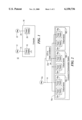
- FIG. 1 is a block diagram of a system for accomplishing this invention
- FIG. 2 is a more detailed example of how FIG. 1 may be applied
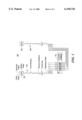
- FIG. 3 is a more detailed schematic diagram of FIG. 1.
- System 10 for distributing continuous, uninterrupted power to a computer system 18.
- System 10 includes independent power sources 12 and 22 that supply power via independent distribution paths 14 and 24 to independent internal power supplies 16 and 26 within the computer, communication, or critical electronic system 18.
- Power sources 12 and 22 could be electric utility services, power conditioners such as transient protectors, voltage regulators or similar power quality conditioning devices, uninterruptible power supplies, batteries, and generators or any combination thereof.
- power supply used to describe 16 and 26 is not intended to prevent a motor or any other load not requiring a power supply from being the consumer of the electrical energy supplied by power paths 14 and 24.
- a typical system 10 might be comprised of hundreds of separate critical loads each represented by 18.
- System 10 has no single point of potential power failure and all elements of the system can be maintained without interruption to critical computer system processing. That is, a failure or disturbance along any one power path, including the power source or the internal load power supply, will have no effect on the continued operation of the computer, communication, or electronic system.
- the system illustrated in FIG. 1 uses two power supplies, two power paths, and two power sources, but this is not an inherent limitation. Any number greater than one is acceptable.
- One of the drawbacks to the system illustrated in FIG. 1 is that when a portion of the system is disabled for maintenance or repair activities, a single disturbance or failure in the active portion may cause a system failure. This vulnerability can be overcome by using three or more redundant elements.
- While the system shown in FIG. 1 uses two totally independent redundant elements, it is possible to use less than two power sources 12 and 22 and still get many of the invention's benefits.
- one application might use a single commercial utility power source 12a. This power source would be common to power path 14 and input to a power conditioner or uninterruptible power supply 22a. The output of 22a would be the independent power source for power path 24. Power paths 14 and 24 would distribute power to critical devices 19A, 19B, and 19C which together comprise all the electrical consumption of computer system 18a.
- the three devices, 19A-19C, shown on FIG. 2 are not intended to be a limitation.
- computer system 18a might be composed of literally hundreds of critical, functionally interrelated devices without limit.
- devices 19A-19C might actually represent entire interrelated and/or interdependent computer, communication, electronic, or other systems each of which in turn are composed of multiple interrelated devices.
- FIG. 2 provides many of same benefits as FIG. 1 at lower cost provided a malfunction does not simultaneously occur in the UPS or power conditioner 22a and the common utility power source 12a. Many variations of FIG. 2 are possible based on the degree of power protection desired and the amount of investment available.
- Both independent power supplies 16 and 26 shown in FIG. 1 are preferably energized continuously so that they are always known to be working and there is no transfer time if a failure occurs. However, the system may also be operated with only one power supply if a suitable means for transferring the protected load(s) to an alternate power supply(s) or to an alternate power path is included so that a disruption does not affect the operation of the critical device(s). Examples of how device power supplies can be internally connected to accomplish such switching are shown in U.S. Pat. Nos. 4,607,330, 3,679,571, and 4,638,175, all incorporated by reference.
- FIG. 3 discloses one more detailed application of FIG. 1 for uninterruptibly generating and distributing power to critical computer hardware equipment devices 18A through 18E.
- Each such critical equipment device would have redundant and independent internal power supplies such as 16a and 26a of FIG. 2 which would be connected respectively to external independent power distribution paths 14a and 24a.
- power source 12aa includes uninterruptable power supply 27 which may be powered by utility power 28, generator power 29 and/or battery power 30.
- Power source 22aa which is an uninterruptable power supply may be similarly powered.
- Each power distribution path 14a and 24a would be supplied by raw power or by independent power conditioners or by uninterruptible power supply systems (or a combination thereof) 27 and 22aa which would receive energy from the commercial electric utility, from generators, or from batteries.
Abstract
Description
Claims (12)
Priority Applications (1)
| Application Number | Priority Date | Filing Date | Title |
|---|---|---|---|
| US08/718,616 US6150736A (en) | 1992-02-28 | 1996-09-23 | Redundant electrical power source, distribution and consumption system |
Applications Claiming Priority (4)
| Application Number | Priority Date | Filing Date | Title |
|---|---|---|---|
| US84331392A | 1992-02-28 | 1992-02-28 | |
| US25746694A | 1994-06-08 | 1994-06-08 | |
| US52411295A | 1995-08-22 | 1995-08-22 | |
| US08/718,616 US6150736A (en) | 1992-02-28 | 1996-09-23 | Redundant electrical power source, distribution and consumption system |
Related Parent Applications (1)
| Application Number | Title | Priority Date | Filing Date |
|---|---|---|---|
| US52411295A Continuation | 1992-02-28 | 1995-08-22 |
Publications (1)
| Publication Number | Publication Date |
|---|---|
| US6150736A true US6150736A (en) | 2000-11-21 |
Family
ID=27401044
Family Applications (1)
| Application Number | Title | Priority Date | Filing Date |
|---|---|---|---|
| US08/718,616 Expired - Fee Related US6150736A (en) | 1992-02-28 | 1996-09-23 | Redundant electrical power source, distribution and consumption system |
Country Status (1)
| Country | Link |
|---|---|
| US (1) | US6150736A (en) |
Cited By (23)
| Publication number | Priority date | Publication date | Assignee | Title |
|---|---|---|---|---|
| US6498966B1 (en) * | 1997-09-17 | 2002-12-24 | Aakerlund John | Method and system for distribution of stand-by electric power |
| US20030109965A1 (en) * | 2001-12-11 | 2003-06-12 | Mikel Gee | Distributed power delivery system |
| US20040070281A1 (en) * | 2002-10-15 | 2004-04-15 | Carolina Tractor & Equipment Company | Method and apparatus for isolating a cogeneration system from a utility source |
| WO2004070907A2 (en) * | 2003-02-04 | 2004-08-19 | Garland Charles Ii | Energy grid management method |
| US20060028347A1 (en) * | 2003-07-11 | 2006-02-09 | Ziejewski Steven J | Apparatus and method for protecting an uninterruptible power supply and critical loads connected thereto |
| US20070014166A1 (en) * | 2005-07-18 | 2007-01-18 | Leonid Goldin | Redundancy power for communication devices |
| WO2007085495A1 (en) * | 2006-01-30 | 2007-08-02 | Robert Bosch Gmbh | Uninterrupted power supply |
| US20090033154A1 (en) * | 2007-08-03 | 2009-02-05 | Ragingwire Enterprise Solutions, Inc. | Redundant isolation and bypass of critical power equipment |
| US20090033153A1 (en) * | 2007-08-03 | 2009-02-05 | Ragingwire Enterprise Solutions, Inc. | Scalable distributed redundancy |
| US7607896B2 (en) | 2006-04-28 | 2009-10-27 | Baker Hughes Incorporated | Systems and methods for power ride-through in variable speed drives |
| US20100141036A1 (en) * | 2007-01-25 | 2010-06-10 | Cru Acquisition Group, Llc | Uninterruptible a/c power supply transfer unit |
| US8030800B1 (en) * | 2009-04-08 | 2011-10-04 | William J Terrell | Integrated power sources for mobile electronic devices |
| WO2012047453A1 (en) | 2010-09-28 | 2012-04-12 | Amazon Technologies, Inc. | Method and system for establishing a power feed to systems during operation |
| DE10231160B4 (en) * | 2001-07-30 | 2012-10-11 | Hewlett-Packard Development Co., L.P. | Uninterruptible power supply |
| CN103633729A (en) * | 2013-01-23 | 2014-03-12 | 世源科技工程有限公司 | Distribution system for machine room of data center |
| US9986652B1 (en) | 2007-06-14 | 2018-05-29 | Switch, Ltd. | Facility including externally disposed data center air handling units |
| US10028415B1 (en) | 2007-06-14 | 2018-07-17 | Switch, Ltd. | Electronic equipment data center and server co-location facility configurations and method of using the same |
| US10158248B2 (en) | 2014-12-15 | 2018-12-18 | Kohler Co. | Communication failure handling |
| US10178796B2 (en) | 2007-06-14 | 2019-01-08 | Switch, Ltd. | Electronic equipment data center or co-location facility designs and methods of making and using the same |
| US10416743B2 (en) * | 2017-03-23 | 2019-09-17 | Nec Corporation | Power supply system |
| US10888034B2 (en) | 2007-06-14 | 2021-01-05 | Switch, Ltd. | Air handling unit with a canopy thereover for use with a data center and method of using the same |
| US11275413B2 (en) | 2007-06-14 | 2022-03-15 | Switch, Ltd. | Data center air handling unit including uninterruptable cooling fan with weighted rotor and method of using the same |
| US11825627B2 (en) | 2016-09-14 | 2023-11-21 | Switch, Ltd. | Ventilation and air flow control with heat insulated compartment |
Citations (13)
| Publication number | Priority date | Publication date | Assignee | Title |
|---|---|---|---|---|
| US3398292A (en) * | 1965-07-19 | 1968-08-20 | North Electric Co | Current supply apparatus |
| US4114048A (en) * | 1976-03-10 | 1978-09-12 | Westinghouse Electric Corp. | Load balancing system for ups rectifiers |
| US4323788A (en) * | 1980-10-02 | 1982-04-06 | Borg-Warner Corporation | D-C Power supply for providing non-interruptible d-c voltage |
| US4467220A (en) * | 1977-07-15 | 1984-08-21 | Ronald Page | Power switching apparatus |
| US4525656A (en) * | 1982-08-24 | 1985-06-25 | Mitsubishi Denki Kabushiki Kaisha | Apparatus for operating plural poly phase A.C. motors having a common load |
| US4607330A (en) * | 1983-11-29 | 1986-08-19 | Parallel Computers, Inc. | Fault-tolerant power supply system |
| US4645940A (en) * | 1982-09-27 | 1987-02-24 | Grumman Aerospace Corporation | Interrupt-free, unregulated power supply |
| US4897563A (en) * | 1988-08-01 | 1990-01-30 | Itt Corporation | N-way MMIC redundant switch |
| US5012121A (en) * | 1990-03-22 | 1991-04-30 | The United States Of America As Represented By The Secretary Of The Navy | Electrical power supply for short term power interruptions |
| US5057697A (en) * | 1990-03-22 | 1991-10-15 | The United States Of America As Represented By The Secretary Of The Navy | DC uninterrupted power supply having instantaneous switching followed by low impedance switching |
| US5081367A (en) * | 1990-07-06 | 1992-01-14 | Westinghouse Electric Corp. | Electric power system with maintenance bypass for uninterruptible power supply using closed transition operation |
| US5138184A (en) * | 1990-01-22 | 1992-08-11 | Powertrol, Inc. | Solid state static power transfer mechanism |
| US5194757A (en) * | 1990-11-20 | 1993-03-16 | Grumman Aerospace Corporation | Uninterruptible power supply |
-
1996
- 1996-09-23 US US08/718,616 patent/US6150736A/en not_active Expired - Fee Related
Patent Citations (13)
| Publication number | Priority date | Publication date | Assignee | Title |
|---|---|---|---|---|
| US3398292A (en) * | 1965-07-19 | 1968-08-20 | North Electric Co | Current supply apparatus |
| US4114048A (en) * | 1976-03-10 | 1978-09-12 | Westinghouse Electric Corp. | Load balancing system for ups rectifiers |
| US4467220A (en) * | 1977-07-15 | 1984-08-21 | Ronald Page | Power switching apparatus |
| US4323788A (en) * | 1980-10-02 | 1982-04-06 | Borg-Warner Corporation | D-C Power supply for providing non-interruptible d-c voltage |
| US4525656A (en) * | 1982-08-24 | 1985-06-25 | Mitsubishi Denki Kabushiki Kaisha | Apparatus for operating plural poly phase A.C. motors having a common load |
| US4645940A (en) * | 1982-09-27 | 1987-02-24 | Grumman Aerospace Corporation | Interrupt-free, unregulated power supply |
| US4607330A (en) * | 1983-11-29 | 1986-08-19 | Parallel Computers, Inc. | Fault-tolerant power supply system |
| US4897563A (en) * | 1988-08-01 | 1990-01-30 | Itt Corporation | N-way MMIC redundant switch |
| US5138184A (en) * | 1990-01-22 | 1992-08-11 | Powertrol, Inc. | Solid state static power transfer mechanism |
| US5012121A (en) * | 1990-03-22 | 1991-04-30 | The United States Of America As Represented By The Secretary Of The Navy | Electrical power supply for short term power interruptions |
| US5057697A (en) * | 1990-03-22 | 1991-10-15 | The United States Of America As Represented By The Secretary Of The Navy | DC uninterrupted power supply having instantaneous switching followed by low impedance switching |
| US5081367A (en) * | 1990-07-06 | 1992-01-14 | Westinghouse Electric Corp. | Electric power system with maintenance bypass for uninterruptible power supply using closed transition operation |
| US5194757A (en) * | 1990-11-20 | 1993-03-16 | Grumman Aerospace Corporation | Uninterruptible power supply |
Cited By (38)
| Publication number | Priority date | Publication date | Assignee | Title |
|---|---|---|---|---|
| US6498966B1 (en) * | 1997-09-17 | 2002-12-24 | Aakerlund John | Method and system for distribution of stand-by electric power |
| DE10231160B4 (en) * | 2001-07-30 | 2012-10-11 | Hewlett-Packard Development Co., L.P. | Uninterruptible power supply |
| US7155320B2 (en) | 2001-12-11 | 2006-12-26 | General Electric Company | Distributed power delivery system |
| US20030109965A1 (en) * | 2001-12-11 | 2003-06-12 | Mikel Gee | Distributed power delivery system |
| US20040070281A1 (en) * | 2002-10-15 | 2004-04-15 | Carolina Tractor & Equipment Company | Method and apparatus for isolating a cogeneration system from a utility source |
| WO2004070907A2 (en) * | 2003-02-04 | 2004-08-19 | Garland Charles Ii | Energy grid management method |
| WO2004070907A3 (en) * | 2003-02-04 | 2005-05-12 | Charles Ii Garland | Energy grid management method |
| US7132951B2 (en) * | 2003-07-11 | 2006-11-07 | Liebert Corporation | Apparatus and method for protecting an uninterruptible power supply and critical loads connected thereto |
| US20060028347A1 (en) * | 2003-07-11 | 2006-02-09 | Ziejewski Steven J | Apparatus and method for protecting an uninterruptible power supply and critical loads connected thereto |
| US20070014166A1 (en) * | 2005-07-18 | 2007-01-18 | Leonid Goldin | Redundancy power for communication devices |
| US7547991B2 (en) | 2005-07-18 | 2009-06-16 | Cisco Technology, Inc. | Redundancy power for communication devices |
| WO2007085495A1 (en) * | 2006-01-30 | 2007-08-02 | Robert Bosch Gmbh | Uninterrupted power supply |
| US7607896B2 (en) | 2006-04-28 | 2009-10-27 | Baker Hughes Incorporated | Systems and methods for power ride-through in variable speed drives |
| US8076798B2 (en) | 2007-01-25 | 2011-12-13 | CRU Acquistion Group, LLC | Uninterruptible A/C power supply transfer unit |
| US20100141036A1 (en) * | 2007-01-25 | 2010-06-10 | Cru Acquisition Group, Llc | Uninterruptible a/c power supply transfer unit |
| US11275413B2 (en) | 2007-06-14 | 2022-03-15 | Switch, Ltd. | Data center air handling unit including uninterruptable cooling fan with weighted rotor and method of using the same |
| US11622484B2 (en) | 2007-06-14 | 2023-04-04 | Switch, Ltd. | Data center exterior wall penetrating air handling technology |
| US10888034B2 (en) | 2007-06-14 | 2021-01-05 | Switch, Ltd. | Air handling unit with a canopy thereover for use with a data center and method of using the same |
| US9999166B1 (en) | 2007-06-14 | 2018-06-12 | Switch, Ltd. | Integrated wiring system for a data center |
| US11889630B2 (en) | 2007-06-14 | 2024-01-30 | Switch, Ltd. | Data center facility including external wall penetrating air handling units |
| US10356939B2 (en) | 2007-06-14 | 2019-07-16 | Switch, Ltd. | Electronic equipment data center or co-location facility designs and methods of making and using the same |
| US10356968B2 (en) | 2007-06-14 | 2019-07-16 | Switch, Ltd. | Facility including externally disposed data center air handling units |
| US10178796B2 (en) | 2007-06-14 | 2019-01-08 | Switch, Ltd. | Electronic equipment data center or co-location facility designs and methods of making and using the same |
| US10028415B1 (en) | 2007-06-14 | 2018-07-17 | Switch, Ltd. | Electronic equipment data center and server co-location facility configurations and method of using the same |
| US9986652B1 (en) | 2007-06-14 | 2018-05-29 | Switch, Ltd. | Facility including externally disposed data center air handling units |
| US8212401B2 (en) * | 2007-08-03 | 2012-07-03 | Stratascale, Inc. | Redundant isolation and bypass of critical power equipment |
| US8294297B2 (en) * | 2007-08-03 | 2012-10-23 | Ragingwire Enterprise Solutions, Inc. | Scalable distributed redundancy |
| US20090033153A1 (en) * | 2007-08-03 | 2009-02-05 | Ragingwire Enterprise Solutions, Inc. | Scalable distributed redundancy |
| US20090033154A1 (en) * | 2007-08-03 | 2009-02-05 | Ragingwire Enterprise Solutions, Inc. | Redundant isolation and bypass of critical power equipment |
| US8030800B1 (en) * | 2009-04-08 | 2011-10-04 | William J Terrell | Integrated power sources for mobile electronic devices |
| US9735576B2 (en) | 2010-09-28 | 2017-08-15 | Amazon Technologies, Inc. | Method and system for establishing a power feed to systems during operation |
| EP2622700A4 (en) * | 2010-09-28 | 2016-08-24 | Amazon Tech Inc | Method and system for establishing a power feed to systems during operation |
| US10658838B2 (en) | 2010-09-28 | 2020-05-19 | Amazon Technologies, Inc. | Method and system for establishing a power feed to systems during operation |
| WO2012047453A1 (en) | 2010-09-28 | 2012-04-12 | Amazon Technologies, Inc. | Method and system for establishing a power feed to systems during operation |
| CN103633729A (en) * | 2013-01-23 | 2014-03-12 | 世源科技工程有限公司 | Distribution system for machine room of data center |
| US10158248B2 (en) | 2014-12-15 | 2018-12-18 | Kohler Co. | Communication failure handling |
| US11825627B2 (en) | 2016-09-14 | 2023-11-21 | Switch, Ltd. | Ventilation and air flow control with heat insulated compartment |
| US10416743B2 (en) * | 2017-03-23 | 2019-09-17 | Nec Corporation | Power supply system |
Similar Documents
| Publication | Publication Date | Title |
|---|---|---|
| US6150736A (en) | Redundant electrical power source, distribution and consumption system | |
| US10928878B2 (en) | Reserve power system for data center | |
| US7129599B2 (en) | Dual feed power supply systems with enhanced power quality | |
| EP0215348B1 (en) | Redundant power supply system | |
| US5764504A (en) | Uninterruptible power supply with fault tolerance in a high voltage environment | |
| US9081568B1 (en) | Electrical power system with automatic transfer switch failure protection | |
| US5920129A (en) | Uninterruptible power supply having solid state transfer switch and method of operation thereof | |
| US10014713B1 (en) | Redundant secondary power support system | |
| CN102782981B (en) | Power supplies for electronic devices | |
| CN112542830B (en) | Power supply system | |
| GB2281458A (en) | Apparatus for managing power supply to a telecommunications base station | |
| US10666087B2 (en) | System for redundant power supply to a data center | |
| US20040084966A1 (en) | Simple automated source switch | |
| CN110690755A (en) | Communication power supply system | |
| US11881742B2 (en) | Systems and methods for supplying uninterruptible power | |
| US20170126019A1 (en) | Systems and methods for redundant power supply | |
| Rutledge | Distributed Power" Time for a Second Look" | |
| Rostek | Power system design for massive parallel computer systems | |
| CN115398769B (en) | Redundant power supply system with multi-loop power supply and power distribution device | |
| CN210806838U (en) | Communication power supply system | |
| CN216290318U (en) | IT equipment power supply system and equipment system | |
| Jovanovic | Dual AC-input power system architectures | |
| RU2183042C2 (en) | Universal power supply system for mobile equipment | |
| JPH0879986A (en) | Static uninterruptible power source | |
| Le | New UPS system configuration that will improve energy efficiency |
Legal Events
| Date | Code | Title | Description |
|---|---|---|---|
| FPAY | Fee payment |
Year of fee payment: 4 |
|
| AS | Assignment |
Owner name: THE UPTIME INSTITUTE, INC., NEW MEXICO Free format text: ASSIGNMENT OF ASSIGNORS INTEREST;ASSIGNOR:BRILL, KENNETH G.;REEL/FRAME:019382/0560 Effective date: 20070522 |
|
| AS | Assignment |
Owner name: THE UPTIME INSTITUTE, INC., NEW MEXICO Free format text: ASSIGNMENT OF ASSIGNORS INTEREST;ASSIGNOR:BRILL, KENNETH G.;REEL/FRAME:019466/0361 Effective date: 20061231 |
|
| FPAY | Fee payment |
Year of fee payment: 8 |
|
| AS | Assignment |
Owner name: UPTIME INSTITUTE, LLC,NEW YORK Free format text: ASSIGNMENT OF ASSIGNORS INTEREST;ASSIGNOR:THE UPTIME INSTITUTE, INC.;REEL/FRAME:023870/0723 Effective date: 20100125 |
|
| REMI | Maintenance fee reminder mailed | ||
| LAPS | Lapse for failure to pay maintenance fees | ||
| STCH | Information on status: patent discontinuation |
Free format text: PATENT EXPIRED DUE TO NONPAYMENT OF MAINTENANCE FEES UNDER 37 CFR 1.362 |
|
| FP | Lapsed due to failure to pay maintenance fee |
Effective date: 20121121 |
|
| AS | Assignment |
Owner name: STIFEL BANK & TRUST, AS ADMINISTRATIVE AGENT, MISSOURI Free format text: SECURITY INTEREST;ASSIGNORS:UPTIME INSTITUTE PROFESSIONAL SERVICES, LLC;UPTIME INSTITUTE, LLC;REEL/FRAME:058842/0006 Effective date: 20220112 |