US6150837A - Enhanced field programmable gate array - Google Patents
Enhanced field programmable gate array Download PDFInfo
- Publication number
- US6150837A US6150837A US08/807,455 US80745597A US6150837A US 6150837 A US6150837 A US 6150837A US 80745597 A US80745597 A US 80745597A US 6150837 A US6150837 A US 6150837A
- Authority
- US
- United States
- Prior art keywords
- gate array
- programmable gate
- array region
- mask
- region
- Prior art date
- Legal status (The legal status is an assumption and is not a legal conclusion. Google has not performed a legal analysis and makes no representation as to the accuracy of the status listed.)
- Expired - Lifetime
Links
Images

Classifications
-
- H—ELECTRICITY
- H03—ELECTRONIC CIRCUITRY
- H03K—PULSE TECHNIQUE
- H03K19/00—Logic circuits, i.e. having at least two inputs acting on one output; Inverting circuits
- H03K19/02—Logic circuits, i.e. having at least two inputs acting on one output; Inverting circuits using specified components
- H03K19/173—Logic circuits, i.e. having at least two inputs acting on one output; Inverting circuits using specified components using elementary logic circuits as components
- H03K19/177—Logic circuits, i.e. having at least two inputs acting on one output; Inverting circuits using specified components using elementary logic circuits as components arranged in matrix form
- H03K19/17748—Structural details of configuration resources
- H03K19/17768—Structural details of configuration resources for security
-
- H—ELECTRICITY
- H03—ELECTRONIC CIRCUITRY
- H03K—PULSE TECHNIQUE
- H03K19/00—Logic circuits, i.e. having at least two inputs acting on one output; Inverting circuits
- H03K19/02—Logic circuits, i.e. having at least two inputs acting on one output; Inverting circuits using specified components
- H03K19/173—Logic circuits, i.e. having at least two inputs acting on one output; Inverting circuits using specified components using elementary logic circuits as components
- H03K19/1733—Controllable logic circuits
- H03K19/1735—Controllable logic circuits by wiring, e.g. uncommitted logic arrays
- H03K19/1736—Controllable logic circuits by wiring, e.g. uncommitted logic arrays in which the wiring can be modified
-
- H—ELECTRICITY
- H03—ELECTRONIC CIRCUITRY
- H03K—PULSE TECHNIQUE
- H03K19/00—Logic circuits, i.e. having at least two inputs acting on one output; Inverting circuits
- H03K19/02—Logic circuits, i.e. having at least two inputs acting on one output; Inverting circuits using specified components
- H03K19/173—Logic circuits, i.e. having at least two inputs acting on one output; Inverting circuits using specified components using elementary logic circuits as components
- H03K19/177—Logic circuits, i.e. having at least two inputs acting on one output; Inverting circuits using specified components using elementary logic circuits as components arranged in matrix form
- H03K19/17704—Logic circuits, i.e. having at least two inputs acting on one output; Inverting circuits using specified components using elementary logic circuits as components arranged in matrix form the logic functions being realised by the interconnection of rows and columns
-
- H—ELECTRICITY
- H03—ELECTRONIC CIRCUITRY
- H03K—PULSE TECHNIQUE
- H03K19/00—Logic circuits, i.e. having at least two inputs acting on one output; Inverting circuits
- H03K19/02—Logic circuits, i.e. having at least two inputs acting on one output; Inverting circuits using specified components
- H03K19/173—Logic circuits, i.e. having at least two inputs acting on one output; Inverting circuits using specified components using elementary logic circuits as components
- H03K19/177—Logic circuits, i.e. having at least two inputs acting on one output; Inverting circuits using specified components using elementary logic circuits as components arranged in matrix form
- H03K19/17724—Structural details of logic blocks
- H03K19/17732—Macroblocks
-
- H—ELECTRICITY
- H03—ELECTRONIC CIRCUITRY
- H03K—PULSE TECHNIQUE
- H03K19/00—Logic circuits, i.e. having at least two inputs acting on one output; Inverting circuits
- H03K19/02—Logic circuits, i.e. having at least two inputs acting on one output; Inverting circuits using specified components
- H03K19/173—Logic circuits, i.e. having at least two inputs acting on one output; Inverting circuits using specified components using elementary logic circuits as components
- H03K19/177—Logic circuits, i.e. having at least two inputs acting on one output; Inverting circuits using specified components using elementary logic circuits as components arranged in matrix form
- H03K19/17736—Structural details of routing resources
- H03K19/17744—Structural details of routing resources for input/output signals
-
- H—ELECTRICITY
- H03—ELECTRONIC CIRCUITRY
- H03K—PULSE TECHNIQUE
- H03K19/00—Logic circuits, i.e. having at least two inputs acting on one output; Inverting circuits
- H03K19/02—Logic circuits, i.e. having at least two inputs acting on one output; Inverting circuits using specified components
- H03K19/173—Logic circuits, i.e. having at least two inputs acting on one output; Inverting circuits using specified components using elementary logic circuits as components
- H03K19/177—Logic circuits, i.e. having at least two inputs acting on one output; Inverting circuits using specified components using elementary logic circuits as components arranged in matrix form
- H03K19/1778—Structural details for adapting physical parameters
- H03K19/17796—Structural details for adapting physical parameters for physical disposition of blocks
Definitions
- This invention relates to the field of Field Programmable Gate Arrays (FPGAs).
- FPGAs Field Programmable Gate Arrays
- This invention relates to a method and apparatus of extending the functionality of FPGAs by providing a means for the inclusion of user-specified functions through inclusion of other functional circuitry on the integrated circuit die with the FPGA circuitry, and particularly with such circuitry implemented as mask programmable circuit regions on the integrated circuit.
- An integrated circuit uses a network of metal interconnects between the individual semiconductor components which are patterned with standard photolithographic processes during wafer fabrication. Multiple levels of metallized patterns may be used to increase the flexibility of the interconnects.
- a gate array circuit is an array of uncommitted gates with uncommitted wiring channels. To implement a particular circuit function, the circuit is mapped into the array and the wiring channels and appropriate connections are programmed to implement the necessary wiring connections that form the circuit function.
- a gate array circuit can be programmed to implement virtually any set of functions. Input signals are processed by the programmed circuit to produce the desired set of outputs. Such inputs flow from the user's system, through input buffers, then through the circuit, and finally back out to the user's system via output buffers.
- Such buffers provide any or all of the following input/output (I/O) functions: voltage gain, current gain, level translation, delay, signal isolation, or hysteresis.
- the gate array circuit is described as a mask-programmable gate array.
- the gate array circuit is described as an FPGA.
- the FPGA can be permanently programmed by the user.
- the FPGA can be changeably programmed by the user.
- a mask-programmable gate array offers higher functionality and performance and more efficient use of space while an FPGA offers lower design costs and greater user flexibility.
- a mask-programmable gate array can implement any variety of I/O function and often at a higher speed than an FPGA.
- Other dedicated functional circuitry may also offer higher functionality and performance than its equivalent configured from FPGA components.
- an object of the present invention to provide an improved FPGA which is capable of yielding the functionality, performance, and efficiency of a mask-programmable gate array while maintaining the lower design costs and user flexibility of an FPGA.
- Yet another object of the present invention is to combine FPGA integrated circuit technology with that of other functional circuitry on the same integrated circuit die.
- an enhanced FPGA is disclosed.
- a portion of an integrated circuit die includes dedicated functional circuitry or mask-programmable circuitry to provide critical circuit functions that cannot adequately or cost effectively be implemented using only Field Programmable manufacturing techniques.
- a FPGA integrated circuit comprises a plurality of logic cells or logic modules placed in an array or matrix.
- the array has a set of vertical wiring channels and a set of horizontal wiring channels that are programmed by the user to interconnect the various logic cells to implement the required logic functions.
- Connections to the wiring channels are made by user-programmable interconnect elements situated at the intersection of any two wires to be connected. To make a connection, the user-programmable interconnect element is programmed, resulting in a low impedance electric connection between the two wires.
- Various types of user-programmable interconnect elements such as antifuses, pass transistors, memory cells, non-volatile memory including flash, EEPROMs and EPROMs, may be employed in the architecture of the present invention.
- a plurality of these programmable elements are used to segment the vertical and horizontal channels into shorter wire lengths. These segments may be joined together to form longer wire connections by programming the programmable elements or left as is to provide independent segment wire lengths and allow the same wiring channel position to be used several times for different circuit connections.
- Programming circuitry is typically situated at the edge of the array. Programming and connectivity information is shifted into the programming circuit, and appropriate voltages applied to effect the desired connection patterns.
- the same vertical and horizontal channels that are used for wiring channels in normal operations may be used for programming the various interconnections and to provide complete testing of the array modules and wiring paths. Alternately, direct programming of individual elements may be performed.
- the various circuits and processes for programming user-programmable interconnect elements are well known in the art and are not a part of the present invention. Details of programming are not presented here in order to avoid unnecessarily complicating the disclosure.
- the logic modules used in the FPGA portion of the array may be universal logic elements, which are very efficient in its implementation of random logic functions defined by the use of selected user-programmable elements. Persons of ordinary skill in the art will appreciate that numerous different modules are available.
- At least one portion of the array is not populated by logic modules but instead includes other circuitry.
- the other circuitry comprises a mask-programmable circuit, such as a mask-programmable gate array.
- Other specific embodiments of the invention include circuits such as analog blocks (A/D, D/A, voltage reference, op amps, comparators, PLL, DPLL, DLL, crystal oscillators), specialized digital blocks (SRAM, DRAM, ROM, PROM, EPROM, EEPROM, FIFO, multiplexers, microprocessors, embedded controllers, ALU, floating point processor, DSP. array processor), and specialized 11O functions (GTL, PECL, LVDS, bus controllers for PCI, ISA, EISA, RAMBUS, etc., network transceivers, high speed serial connections).
- Interface circuitry allows connections to be made between the mask-programmable circuit, the logic modules in the array, and I/O circuitry connecting to I/O pins on the integrated circuit.
- one or more logic module locations at or near the interface between the FPGA portion and the mask-programmable portion of the integrated circuit are populated by interface circuits for making connections between FPGA portion and the mask-programmable portion of the integrated circuit.
- the end user chooses from a wide range of functions and specifies them to the manufacturer.
- the manufacturer in turn programs some functions into the integrated circuit using mask-programmable techniques, leaving the user to program other functions into the integrated circuit using the field programmable portion of the integrated circuit.
- the mask-programmable portion of the integrated circuit contains a gate array for implementing a wide range of functions.
- the mask-programmable gate array is connected to the FPGA via a circuit interface portion of the integrated circuit.
- the circuit interface can contain either mask-programmable or Field Programmable circuits for controlling and processing the signals passing from and to both the mask-programmable gate array and the FPGA.
- Each of the mask-programmable gate array, the FPGA, and the circuit interface are connected to an I/O portion of the integrated circuit.
- the I/O portion of the integrated circuit can contain either mask-progranmmable or Field Programmable circuits for controlling and processing the signals passing into the integrated circuit from external sources or out of the integrated circuit to external sources.
- the mask-programmable portion of the integrated circuit contains I/O circuits for implementing a wide range of functions for controlling and processing the signals passing into the integrated circuit from external sources or out of the integrated circuit to external sources.
- the mask-programmable I/O circuits are connected to the FPGA via a circuit interface portion of the integrated circuit.
- the circuit interface can contain either mask-programmable or Field Programmable circuits for controlling and processing the signals passing from and to the FPGA. Both the circuit interface and the FPGA can also receive signals from and send signals to external sources directly.
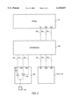
- FIG. 1 is a block diagram of a preferred embodiment of the present invention having both an FPGA region and a mask-programmable gate array region.
- FIG. 2 is a block diagram of a preferred embodiment of an interface circuit according to the present invention interposed between the FPGA region, the mask-programmable region, and an I/O driver of the integrated circuit.
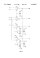
- FIG. 3 is a schematic diagram of a presently preferred embodiment of the interface circuit of FIG. 2.
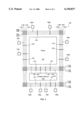
- FIG. 4 is a block diagram of an embodiment of the present invention having both an FPGA region and a mask-programmable gate array region showing an illustrative I/O routing arrangement.
- FIG. 1 a block diagram of a preferred embodiment of an enhanced FPGA integrated circuit 10 is shown.
- the integrated circuit 10 is shown to comprise a number of blocks.
- the number, size, and location of the blocks as shown in FIG. 1 is not critical to the operation of the present invention and the layout shown in FIG. 1 is only for purposes of illustration. Persons of ordinary skill in the art will realize that a large number of alternative implementations are possible which are included within the scope of the present invention.
- the integrated circuit 10 contains an FPGA portion 12.
- the FPGA 12 includes an array of logic function modules and uncommitted wiring channels which are connectable together and to I/O of the integrated circuit 10 via user-programmable interconnect elements as is known in the art.
- the end user may configure the FPGA 12 to perform a wide range of functions into the integrated circuit 10.
- the techniques used to implement user defined functions employing an FPGA are well known to persons of ordinary skill in the art and will not be further disclosed herein.
- the integrated circuit 10 includes regions 14 and 16 of other circuitry.
- the other circuitry is a mask-programmable gate array.
- Persons of ordinary skill in the art will recognize from this disclosure that many other types of circuitry can be employed in regions 14 and 16, subject only to compatibility with the FPGA fabrication process. The number of other types of circuit functions which could be employed in regions 14 and 16 is thus virtually unlimited.
- Persons of ordinary skill in the art will also appreciate that while two regions 14 and 16 are shown in the block diagram of FIG. 1, one such region, or more than two regions could be included in an integrated circuit according to the present invention.
- the mask-programmable gate arrays in regions 14 and 16 includes an array of uncommitted gates with uncommitted wiring channels. During manufacturing, these gates are connected together within the mask-programmable gate array regions 14 and 16 to implement any of a wide range of functions into the integrated circuit 10.
- the functions programmed into the mask-programmable gate array regions 14 and 16 are generally dictated by the user or reflect an industry standard. The techniques used to implement functions employing a mask-programmable gate array are well known to one of ordinary skill in the art and will not be further disclosed herein.
- the integrated circuit 10 includes an interface region 18.
- the interface region 18 includes any number and variety of elements which provide communication between the FPGA portion 12, the mask-programmable gate array regions 14 and 16, and the I/O of the integrated circuit 10.
- the circuit interface elements can be as simple as a direct interconnect between the FPGA region 12 and the mask-programmable gate array regions 14 and 16 or as complicated as a logic module that controls and/or conditions the communication between the FPGA region 12 and the mask-programmable gate array regions 14 and 16.
- the choice of circuit interface elements is generally dictated by the nature of the circuitry disposed in regions 14 and 16 and in the FPGA region 12.
- the techniques used to implement the circuit interface elements are dictated in part by the techniques used to implement the functions in the FPGA 12 and the mask-programmable gate array regions 14 and 16.
- the techniques used to implement the circuit interface elements are well known to one of ordinary skill in the art and will not be further disclosed herein.
- a distributed approach is preferably taken for placement of the I/O connections to the regions 14 and 16 through the matrix of logic modules in the software library used to configure the FPGA portion 12 of integrated circuit 10.
- fixed locations i.e., logic modules
- FPGA routing resources may be brought out to be connectable to the regions 14 and 16 in as even a manner as the layout will allow.
- the integrated circuit 10 also includes an I/O section 20.
- the I/O section 20 provides the necessary elements for communication between the integrated circuit 10 and other components in an external system. While I/O section 20 is shown at a single location in the block diagram of FIG. 1, persons of ordinary skill in the art will recognize that for efficient use, the I/O 20 may be distributed around the area of the die on which integrated circuit 10 is fabricated.
- bonding pads 22a, 22b, 22c, and 22d The physical connection with the external user is provided through bonding pads 22a, 22b, 22c, and 22d.
- bonding pads 22a, 22b, 22c, and 22d can vary widely with the particular application necessary for the operation of the present invention.
- I/O section 20 is connected to I/O interface 24 which includes any number and variety of mask-programmable and/or field programmable elements which provides communication between the external user and any or all of the FPGA region 12, the mask-programmable gate array regions 14 and 16, and the circuit interface 18 located on the integrated circuit 10.
- I/O interface elements can be as simple as a direct interconnect between the external user and the integrated circuit 10 or as complicated as a logic module that controls and/or conditions the communication between the external user and the integrated circuit 10.
- the choice of I/O interface elements is generally dictated by the user or reflect an industry standard. The techniques used to implement the I/O interface elements are well known to one of ordinary skill in the art and will not be further disclosed herein.
- the increase in performance and functionality of the mask-programmable enhanced FPGA as shown in FIG. 1 is such that a broad range of uses are possible. Some specific uses will now be disclosed, but they by no means represent the full extent of those uses that are possible within the present invention.
- three-state buffers can be programmed into the circuit interface 18 by either Field Programmable or mask-programmable techniques. These three-state buffers can then be utilized to isolate the FPGA region 12 from the mask-programmable gate array 14 and/or vice versa during test or normal operation as desired.
- transistors such as high voltage pass gates can be programmed into the circuit interface 18 and used for isolation.
- the state of the isolation can be determined by the external user through the I/O section 20 by selectively turning the isolation on or off.
- mask-programmable gate array regions 14 or 16 Another use for either one of mask-programmable gate array regions 14 or 16 is to configure it as a decryption circuit.
- This decryption circuit receives encrypted configuration data from the external user, decrypts this data, and passes the decrypted data on to the FPGA region 12.
- mask-programmable gate array region 14 or 16 may be configured as one of numerous known decryption circuits.
- the FPGA region 12 of the integrated circuit is programmed with a configuration control circuit that receives the decrypted configuration data and utilizes it to configure the programmable elements of the FPGA 12 to perform the function desired by the external user.
- the configuration of the FPGA 12 can be maintained in confidence from everyone except the persons who generated the encrypted configuration data. This is especially useful if the FPGA 12 employs any of the known user re-programmable interconnect elements.
- the ability to reprogram the changeably programmable circuit elements in the FPGA 12 is another use that the mask-programmable gate array regions 14 and 16 can be programmed to fulfill. First, this enables a function performed by the FPGA region 12 to be changed based on established criteria. Second, this allows the FPGA region 12 to be programmed in such a way that a function performed by the mask-programmable gate array 14 is changed.
- the mask-programmable gate array regions 14 and 16 can be programmed with a built-in test sequence for testing the FPGA 12 on command from the external user or automatically on startup. Numerous such test circuits are known to persons of ordinary skill in the art.
- the mask-programmable gate array regions 14 and 16 can also be employed to provide a standardized interfaces between the external user and the FPGA 12.
- the mask-programmable gate array regions 14 and 16 can perform bus interface functions such as PCI, VME, or USB.
- the mask-programmable gate array regions 14 and 16 can perform local area network (LAN) functions such as Ethernet, Frame Relay, and ATM.
- LAN local area network
- Another use for either one of the mask-programmable gate array regions 14 and 16 is to configure it to be a microprocessor or embedded controller such as one of the numerous popular designs in use in the industry.
- the mask-programmable gate array regions 14 and 16 can be programmed with a high drive, low skew clock driver for connecting to the high fanout load.
- Low skew clock driver circuits are well known in the art.
- the process employed to create and to program the mask-programmable enhanced FPGA as shown in FIG. 1 is based on a combination of techniques that are well known to one of ordinary skill in the art. The general process is outlined below.
- the general need that the integrated circuit 10 is to fulfill is determined. This may be based entirely on specifications supplied by a user or group of users or on a decision made solely by the manufacturer based upon market analysis.
- the manufacturer lays out the details of the integrated circuit 10 making sure to allow as much flexibility as possible. This involves selecting the relative sizes of the blocks of the integrated circuit 10 and the logic circuits that will be available within each block. The manufacturer then fabricates the integrated circuit 10 and programs some functions into the integrated circuit 10 using mask-programmable techniques. These functions can be as simple as an interconnect or as complicated as a standard interface or microprocessor.
- the integrated circuit 10 is then either shipped to the user who programs additional functions into the integrated circuit 10 using the user-programmable interconnect elements.
- Persons of ordinary skill in the art will appreciate that the mask programming step could be performed to individual user specifications.
- the result of the programming is an integrated circuit 10 that contains a circuit that will perform an enhanced user defined function.
- the integrated circuit 10 includes reconfigurable user-programmable elements
- the final configuration of the integrated circuit can be changed by either the manufacturer or the user and the resulting function may also be changed. This results in a more flexible integrated circuit.
- the regions 14 and 16 may be programmed to operate in one of a number of predefined modes by configuring them.
- one or more I/O pins of the integrated circuit may be used to configure the function of the regions 14 and 16.
- these I/O pins may be used for normal I/O functions. Assigning dual functions to I/O pins is well known in the art.
- regions 14 and 16 may be disabled, allowing the integrated circuit to be sold as an FPGA alone. If these regions are not recognized as being present by the programming software, no circuitry appears in the net list describing the integrated circuit.
- Interface circuit 30 for use between the FPGA region 12, one of mask-programmable regions 14 or 16, and an I/O driver 32 of the integrated circuit.
- Interface circuit 30 may be used for each I/O pin 34 which has direct access to the mask-programmable regions 14 or 16.
- pad driver circuit 32 comprises a bidirectional buffer including input buffer 38 and tri-stateable output buffer 40.
- the three signal lines associated with pad driver circuit 32 are pad input (PI) line 42, pad output (PO) line 44, and pad enable (PE) line 46.
- PI line 42 carries input signals from the output of input buffer 38
- PO line 44 carries output signals to the input of output buffer 40
- PE line 46 is the tri-state control for output buffer 40.
- the operation of pad driver circuit 32 is well known in the art.
- interface circuit 30 provides a way to allow pad driver circuit 32 to communicate with both FPGA portion 12 and mask-programmable regions 14 or 16 of integrated circuit 10.
- FPGA portion 12 and mask-programmable regions 14 or 16 has three signal lines associated with it.
- FPGA portion 12 has signal input (FI) line 48, signal output (FO) line 50, and signal enable (FE) line 52.
- FI line 48 carries input signals into FPGA portion 12
- FO line 50 carries output signals from FPGA portion 12
- FE line 52 is a tri-state control line.
- Mask-programmable regions 14 and 16 have three signal lines associated with them: signal input (GI) line 54, signal output (GO) line 56, and signal enable (GE) line 58.
- GI line 54 carries input signals into mask programmable region 14 or 16
- GO line 56 carries output signals from mask programmable region 14 or 16
- GE line 58 is a tri-state control line.
- an interface 30 may be provided for each I/O of the integrated circuit 10.
- a first multiplexer 60 has a control input driven by a control signal Q0, a first data input driven by the FE signal, a second data input driven by the GE input signal, and an output presenting the PE signal.
- a second multiplexer 62 has a control input driven by the control signal Q0, a first data input driven by the FO signal, a second data input driven by the GO input signal, and an output presenting the PO signal.
- a third multiplexer 64 has a control input, a first data input driven by the PI signal, a second data input driven by the GO input signal, and an output presenting the FI signal.
- a fourth multiplexer 66 has a control input, a first data input driven by the PI signal, a second data input driven by the FO input signal, and an output presenting the GI signal.
- First through fourth multiplexers 60, 62, 64, and 66 are preferably formed using tri-state buffers rather than pass transistors. The use of these tri-state buffers allows for driving long lines.
- a fifth multiplexer 68 has a control input driven by a control signal Q1, a first data input driven by the PE signal, a second data input driven by a control signal Q2, and an output driving the control input of the third multiplexer 64.
- a sixth multiplexer 70 has a control input driven by a control signal Q3, a first data input driven by the PE signal, a second data input driven by the Q4 input signal, and an output driving the control input of the fourth multiplexer 66.
- Control bit Q0 allows either the FPGA region 12 or the mask-programmable region 14 or 16 to control the tri-stateable output buffer 40 by selecting either the FO and FE lines or the CO and GE lines as the source for the PO and PE lines, respectively.
- the Q0 through Q4 control bits may be controlled by user-programmable interconnect elements which may be selectively programmed during FPGA device programming by the end user.
- each of the Q0 through Q4 nodes may separately be actively or passively pulled up unless pulled down by programming a user-programmable interconnect element associated therewith.
- node Q0 is illustratively shown connected to VDD through pullup device 72 and to ground through user-programmable interconnect element shown as a circle identified by reference numeral 74.
- Node Q1 is illustratively shown connected to VDD through pullup device 76 and to ground through user-programmable interconnect element shown as a circle identified by reference numeral 78.
- Node Q2 is illustratively shown connected to VDD through pullup device 80 and to ground through user-programmable interconnect element shown as a circle identified by reference numeral 82.
- Node Q3 is illustratively shown connected to VDD through pullup device 84 and to ground through user-programmable interconnect element shown as a circle identified by reference numeral 86.
- Node Q4 is illustratively shown connected to VDD through pullup device 88 and to ground through user-programmable interconnect element shown as a circle identified by reference numeral 90.
- Tables 1 and 2 are truth tables defining the operation of the interface 30.
- the Q0 through Q4 control signals may also be controlled from registers so as to alter the signal path definitions as a function of time as is known in the art.
- FIG. 4 is a block diagram of a preferred embodiment of an integrated circuit 100 according to the present invention having both an FPGA region 102 and another circuit region 104 which may be, for example, a mask-programmable gate array region.
- FIG. 4 shows another illustrative I/O routing arrangement for use in the present invention.
- a plurality of I/O pads 106a through 106j are disposed about the periphery of the integrated circuit die as is well known in the art. Those of ordinary skill in the art will recognize that I/O buffers (not shown in FIG. 4) may be provided.
- Each wiring channel includes a plurality of interconnect conductors.
- FIG. 4 Several such wiring channels are shown in FIG. 4 disposed in both the horizontal and vertical directions. Those of ordinary skill in the art will recognize, however, that many more wiring channels than are shown in FIG. 4 will typically exist in an integrated circuit fabricated according to the teachings of the present invention.
- the uppermost horizontal wiring channel includes interconnect conductors 108a through 108d.
- the center horizontal wiring channel includes interconnect conductors 100a through 110d.
- the lower horizontal wiring channel includes interconnect conductors 112a through 112d.
- the leftmost vertical wiring channel includes interconnect conductors 114a through 114d.
- the rightmost vertical wiring channel includes interconnect conductors 116a through 116d.
- interconnect conductors can have varying lengths. Some run the full length (or width) of the array and some are segmented into at least two segments in order to maximize the interconnect capability of the integrated circuit 100.
- I/O pads 106a through 106j are hardwired to interconnect conductors and some are programmably connectable to interconnect conductors.
- I/O pads 106a, 106c, 106f, 106h and 106j are hardwired to interconnect conductors 108a, 116d, 112b, 112a, and 114d, respectively.
- I/O pads 106b, 106d, 106e, 106g, and 106i are programmably connectable to any of the interconnect conductors in the wiring channels that their conductors intersect.
- I/O pad 106b is connectable to any of interconnect conductors 108a through 108d via individual user-programmable interconnect elements shown as small circles at the regions where the I/O pad conductor intersects the interconnect conductors.
- interconnect conductors 108a through 108d are programmably connectable to any of interconnect conductors 114a through 114d or any of interconnect conductors 116a through 116d.
- Inputs and outputs of individual logic function modules in the FPGA portion 102 of integrated circuit 100 are programmably connectable to the interconnect conductors in the same manner as described above.
- Illustrative inputs or outputs 118, 120, 122, 124, 126, 128, and 130 are shown intersecting various wiring channels and are shown connectable to individual interconnect conductors contained therein via user-programmable interconnect elements shown as small circles.
- the inputs and outputs of other circuit region 104 of integrated circuit 100 has two types of connectivity to the I/O pads 106a through 106j.
- input/output 132 is hardwired to an interconnect conductor 112b, which is hardwired to I/O pad 106f.
- Input/output 134 is programmably connectable to any one of interconnect conductors 112a through 112d and thus is also programmably connectable to I/O pad 106e via user-programmable interconnect elements.
- Input/outputs 136 and 138 of other circuit region 104 are hardwired to interconnect conductors 110a and 110d, respectively, and input/outputs 140 and 142 of other circuit region 104 are programmably connectable to any one of interconnect conductors 110a through 110d, all via user-programmable interconnect elements.
Abstract
Description
              TABLE 1
______________________________________
FI OPERATION
Q0   Q1     Q2     COMMENTS
______________________________________
0    0      0      Unused
0    0      1      Unused
0    1      0      FPGA input FI always from I/O pad input PI
0    1      1      FPGA input FI always from gate array output GO
1    0      0      Tri-state signal controlled from gate array; FPGA
                   monitors GO when output, PI when input
1    0      1      Unused
1    1      0      FPGA input FI always from I/O pad input PI
1    1      1      FPGA input FI always from gate array output
______________________________________
                   GO
              TABLE 2
______________________________________
GI OPERATION
Q0   Q3    Q4     COMMENTS
______________________________________
0    0     0      Tri-state signal controlled from Gate Array; FPGA
                  monitors GO when output, PI when input
0    0     1      Unused
0    1     0      Gate array input GI always from I/O pad input PI
0    1     1      Gate array input GI always from FPGA output FO
1    0     0      Unused
1    0     1      Unused
1    1     0      Gate Array input GI always from I/O pad input PI
1    1     1      Gate array input GI always from FPGA output
______________________________________
                  FO
Claims (7)
Priority Applications (16)
| Application Number | Priority Date | Filing Date | Title |
|---|---|---|---|
| US08/807,455 US6150837A (en) | 1997-02-28 | 1997-02-28 | Enhanced field programmable gate array |
| KR10-1998-0708623A KR100491662B1 (en) | 1997-02-28 | 1998-02-03 | Enhanced field programmable gate array |
| PCT/US1998/002280 WO1998038741A1 (en) | 1997-02-28 | 1998-02-03 | Enhanced field programmable gate array |
| EP02008838A EP1229651A3 (en) | 1997-02-28 | 1998-02-03 | Enhanced field programmable gate array |
| DE69838462T DE69838462T2 (en) | 1997-02-28 | 1998-02-03 | Improved field programmable gate array |
| JP53766198A JP3926398B2 (en) | 1997-02-28 | 1998-02-03 | Integrated circuit device |
| DE69813974T DE69813974T2 (en) | 1997-02-28 | 1998-02-03 | PROGRAMMABLE GATE FIELD WITH INCREASED PERFORMANCE |
| EP02008839A EP1229652A3 (en) | 1997-02-28 | 1998-02-03 | Enhanced field programmable gate array |
| EP02008836A EP1237280B1 (en) | 1997-02-28 | 1998-02-03 | Enhanced field programmable gate array |
| EP98906180A EP0901716B1 (en) | 1997-02-28 | 1998-02-03 | Enhanced field programmable gate array |
| EP02008837A EP1237281A3 (en) | 1997-02-28 | 1998-02-03 | Enhanced field programmable gate array |
| US09/819,084 US6791353B1 (en) | 1997-02-28 | 2000-09-25 | Enhanced field programmable gate array |
| US10/916,214 US7382155B2 (en) | 1997-02-28 | 2004-08-10 | Enhanced field programmable gate array |
| US12/111,660 US7755386B2 (en) | 1997-02-28 | 2008-04-29 | Enhanced field programmable gate array |
| US12/794,279 US7977970B2 (en) | 1997-02-28 | 2010-06-04 | Enhanced field programmable gate array |
| US13/158,019 US8258811B2 (en) | 1997-02-28 | 2011-06-10 | Enhanced field programmable gate array |
Applications Claiming Priority (1)
| Application Number | Priority Date | Filing Date | Title |
|---|---|---|---|
| US08/807,455 US6150837A (en) | 1997-02-28 | 1997-02-28 | Enhanced field programmable gate array |
Related Child Applications (1)
| Application Number | Title | Priority Date | Filing Date |
|---|---|---|---|
| US09/819,084 Continuation US6791353B1 (en) | 1997-02-28 | 2000-09-25 | Enhanced field programmable gate array |
Publications (1)
| Publication Number | Publication Date |
|---|---|
| US6150837A true US6150837A (en) | 2000-11-21 |
Family
ID=25196411
Family Applications (6)
| Application Number | Title | Priority Date | Filing Date |
|---|---|---|---|
| US08/807,455 Expired - Lifetime US6150837A (en) | 1997-02-28 | 1997-02-28 | Enhanced field programmable gate array |
| US09/819,084 Expired - Lifetime US6791353B1 (en) | 1997-02-28 | 2000-09-25 | Enhanced field programmable gate array |
| US10/916,214 Expired - Fee Related US7382155B2 (en) | 1997-02-28 | 2004-08-10 | Enhanced field programmable gate array |
| US12/111,660 Expired - Fee Related US7755386B2 (en) | 1997-02-28 | 2008-04-29 | Enhanced field programmable gate array |
| US12/794,279 Expired - Fee Related US7977970B2 (en) | 1997-02-28 | 2010-06-04 | Enhanced field programmable gate array |
| US13/158,019 Expired - Fee Related US8258811B2 (en) | 1997-02-28 | 2011-06-10 | Enhanced field programmable gate array |
Family Applications After (5)
| Application Number | Title | Priority Date | Filing Date |
|---|---|---|---|
| US09/819,084 Expired - Lifetime US6791353B1 (en) | 1997-02-28 | 2000-09-25 | Enhanced field programmable gate array |
| US10/916,214 Expired - Fee Related US7382155B2 (en) | 1997-02-28 | 2004-08-10 | Enhanced field programmable gate array |
| US12/111,660 Expired - Fee Related US7755386B2 (en) | 1997-02-28 | 2008-04-29 | Enhanced field programmable gate array |
| US12/794,279 Expired - Fee Related US7977970B2 (en) | 1997-02-28 | 2010-06-04 | Enhanced field programmable gate array |
| US13/158,019 Expired - Fee Related US8258811B2 (en) | 1997-02-28 | 2011-06-10 | Enhanced field programmable gate array |
Country Status (6)
| Country | Link |
|---|---|
| US (6) | US6150837A (en) |
| EP (5) | EP0901716B1 (en) |
| JP (1) | JP3926398B2 (en) |
| KR (1) | KR100491662B1 (en) |
| DE (2) | DE69813974T2 (en) |
| WO (1) | WO1998038741A1 (en) |
Cited By (90)
| Publication number | Priority date | Publication date | Assignee | Title |
|---|---|---|---|---|
| WO2001037154A1 (en) * | 1999-11-16 | 2001-05-25 | Aladdin Knowledge Systems Ltd. | Preventing unauthorized use of active content generator software |
| US6242945B1 (en) * | 1997-03-04 | 2001-06-05 | Xilinx, Inc. | Field programmable gate array with mask programmable I/O drivers |
| US6356637B1 (en) * | 1998-09-18 | 2002-03-12 | Sun Microsystems, Inc. | Field programmable gate arrays |
| US6366120B1 (en) * | 1999-03-04 | 2002-04-02 | Altera Corporation | Interconnection resources for programmable logic integrated circuit devices |
| EP1248372A2 (en) * | 2001-03-19 | 2002-10-09 | Altera Corporation (a Delaware Corporation) | Programmable logic device with high speed serial interface circuitry |
| US20020180484A1 (en) * | 2001-06-04 | 2002-12-05 | Nec Corporation | Semiconductor integrated circuit |
| US20030002523A1 (en) * | 2001-06-08 | 2003-01-02 | Loh Weng Wah | Electronic interface device |
| EP1271784A2 (en) * | 2001-05-06 | 2003-01-02 | Altera Corporation | PLD architecture for flexible placement of IP function blocks |
| US20030160632A1 (en) * | 1998-12-31 | 2003-08-28 | Actel Corporation | Programmable multi-standard I/O architecture for FPGAs |
| WO2003075477A2 (en) * | 2002-03-01 | 2003-09-12 | Xilinx, Inc. | High speed configurable transceiver architecture |
| US6633182B2 (en) | 2001-09-05 | 2003-10-14 | Carnegie Mellon University | Programmable gate array based on configurable metal interconnect vias |
| US20030200520A1 (en) * | 1998-12-14 | 2003-10-23 | Huggins Alan H. | Methods and systems for designing integrated circuit gate arrays |
| US6646466B1 (en) * | 2001-12-05 | 2003-11-11 | Cypress Semiconductor Corp. | Interface scheme for connecting a fixed circuitry block to a programmable logic core |
| US20030214322A1 (en) * | 2002-05-17 | 2003-11-20 | Cox William D. | Distributed ram in a logic array |
| US20040021490A1 (en) * | 1999-08-13 | 2004-02-05 | Xilinx, Inc. | Method and apparatus for timing management in a converted design |
| US20040025005A1 (en) * | 2000-06-13 | 2004-02-05 | Martin Vorbach | Pipeline configuration unit protocols and communication |
| US20040041918A1 (en) * | 2002-09-04 | 2004-03-04 | Chan Thomas M. | Display processor integrated circuit with on-chip programmable logic for implementing custom enhancement functions |
| US6707314B2 (en) * | 2001-05-11 | 2004-03-16 | Seiko Epson Corporation | Integrated circuit device, electronic equipment, and method of placement of an integrated circuit device |
| US6731133B1 (en) | 2000-09-02 | 2004-05-04 | Actel Corporation | Routing structures for a tileable field-programmable gate array architecture |
| US6747479B1 (en) * | 2001-12-05 | 2004-06-08 | Cypress Semiconductor Corp. | Interface scheme for connecting a fixed circuitry block to a programmable logic core |
| US6791353B1 (en) * | 1997-02-28 | 2004-09-14 | Actel Corporation | Enhanced field programmable gate array |
| US20040267520A1 (en) * | 2003-06-27 | 2004-12-30 | Roderick Holley | Audio playback/recording integrated circuit with filter co-processor |
| US20050041149A1 (en) * | 2002-09-04 | 2005-02-24 | Vima Microsystems Corporation | ASIC having dense mask-programmable portion and related system development method |
| WO2005034175A2 (en) | 2003-07-31 | 2005-04-14 | Actel Corporation | Programmable system on a chip |
| US6886143B1 (en) * | 2002-03-29 | 2005-04-26 | Altera Corporation | Method and apparatus for providing clock/buffer network in mask-programmable logic device |
| US20050189962A1 (en) * | 2004-02-20 | 2005-09-01 | Agrawal Om P. | Upgradeable and reconfigurable programmable logic device |
| US20050234572A1 (en) * | 2004-03-30 | 2005-10-20 | Alexandre Heubi | Method and system for data logging in a listening device |
| US6990010B1 (en) | 2003-08-06 | 2006-01-24 | Actel Corporation | Deglitching circuits for a radiation-hardened static random access memory based programmable architecture |
| US7028107B2 (en) | 1996-12-27 | 2006-04-11 | Pact Xpp Technologies Ag | Process for automatic dynamic reloading of data flow processors (DFPS) and units with two- or three- dimensional programmable cell architectures (FPGAS, DPGAS, and the like) |
| US20060132250A1 (en) * | 2004-12-21 | 2006-06-22 | Actel Corporation, A California Corporation | Voltage- and temperature-compensated RC oscillator circuit |
| US20060138544A1 (en) * | 2004-12-29 | 2006-06-29 | Actel Corporation, A California Corporation | ESD protection structure for I/O pad subject to both positive and negative voltages |
| US20060155969A1 (en) * | 2005-01-11 | 2006-07-13 | Fujitsu Limited | Reconfigurable, expandable semiconductor integrated circuit |
| US20060186917A1 (en) * | 2000-06-12 | 2006-08-24 | Altera Corporation, A Corporation Of Delaware | I/O circuitry shared between processor and programmable logic portions of an integrated circuit |
| US7112991B1 (en) * | 2003-12-24 | 2006-09-26 | Altera Corporation | Extended custom instructions |
| US7119398B1 (en) | 2004-12-22 | 2006-10-10 | Actel Corporation | Power-up and power-down circuit for system-on-a-chip integrated circuit |
| US7138824B1 (en) * | 2004-05-10 | 2006-11-21 | Actel Corporation | Integrated multi-function analog circuit including voltage, current, and temperature monitor and gate-driver circuit blocks |
| US20070076120A1 (en) * | 2005-09-30 | 2007-04-05 | Luciano Zoso | NICAM processing method |
| WO2007041140A2 (en) * | 2005-09-30 | 2007-04-12 | Freescale Semiconductor Inc. | Nicam processor |
| US20070177056A1 (en) * | 2002-09-04 | 2007-08-02 | Qinggang Zhou | Deinterlacer using both low angle and high angle spatial interpolation |
| US20070203596A1 (en) * | 2006-02-28 | 2007-08-30 | Accel Semiconductor Corporation | Fm transmission |
| US20070262789A1 (en) * | 2002-06-19 | 2007-11-15 | Viasic, Inc. | Logic array devices having complex macro-cell architecture and methods facilitating use of same |
| US7312633B1 (en) * | 2004-07-22 | 2007-12-25 | Altera Corporation | Programmable routing structures providing shorter timing delays for input/output signals |
| US20080025520A1 (en) * | 2006-07-27 | 2008-01-31 | Mitsuteru Sakai | Volume controlling technique |
| US7334208B1 (en) | 2004-11-09 | 2008-02-19 | Viasic, Inc. | Customization of structured ASIC devices using pre-process extraction of routing information |
| US20080048716A1 (en) * | 2003-07-31 | 2008-02-28 | Actel Corporation | Integrated circuit including programmable logic and external-device chip-enable override control |
| US20080054939A1 (en) * | 2006-08-31 | 2008-03-06 | Viasic, Inc. | Creating high-drive logic devices from standard gates with minimal use of custom masks |
| US7375549B1 (en) | 2006-02-09 | 2008-05-20 | Lattice Semiconductor Corporation | Reconfiguration of programmable logic devices |
| US7378873B1 (en) | 2006-06-02 | 2008-05-27 | Lattice Semiconductor Corporation | Programmable logic device providing a serial peripheral interface |
| US7380131B1 (en) * | 2001-01-19 | 2008-05-27 | Xilinx, Inc. | Copy protection without non-volatile memory |
| US7389487B1 (en) * | 1998-04-28 | 2008-06-17 | Actel Corporation | Dedicated interface architecture for a hybrid integrated circuit |
| US7459931B1 (en) | 2006-04-05 | 2008-12-02 | Lattice Semiconductor Corporation | Programmable logic devices with transparent field reconfiguration |
| US7495970B1 (en) | 2006-06-02 | 2009-02-24 | Lattice Semiconductor Corporation | Flexible memory architectures for programmable logic devices |
| US20090055638A1 (en) * | 2005-04-21 | 2009-02-26 | Toshihisa Nakano | Algorithm update system |
| US20090065813A1 (en) * | 2007-09-06 | 2009-03-12 | Viasic, Inc. | Configuring structured asic fabric using two non-adjacent via layers |
| US20090128699A1 (en) * | 2002-09-04 | 2009-05-21 | Denace Enterprise Co., L.L.C. | Integrated Circuit to Process Data in Multiple Color Spaces |
| US7538574B1 (en) | 2005-12-05 | 2009-05-26 | Lattice Semiconductor Corporation | Transparent field reconfiguration for programmable logic devices |
| US7554358B1 (en) | 2006-04-05 | 2009-06-30 | Lattice Semiconductor Corporation | Programmable logic devices with user non-volatile memory |
| US7570078B1 (en) | 2006-06-02 | 2009-08-04 | Lattice Semiconductor Corporation | Programmable logic device providing serial peripheral interfaces |
| US7627291B1 (en) * | 2005-01-21 | 2009-12-01 | Xilinx, Inc. | Integrated circuit having a routing element selectively operable to function as an antenna |
| US7650448B2 (en) | 1996-12-20 | 2010-01-19 | Pact Xpp Technologies Ag | I/O and memory bus system for DFPS and units with two- or multi-dimensional programmable cell architectures |
| US7657877B2 (en) | 2001-06-20 | 2010-02-02 | Pact Xpp Technologies Ag | Method for processing data |
| US7657861B2 (en) | 2002-08-07 | 2010-02-02 | Pact Xpp Technologies Ag | Method and device for processing data |
| US7782087B2 (en) | 2002-09-06 | 2010-08-24 | Martin Vorbach | Reconfigurable sequencer structure |
| US7822881B2 (en) | 1996-12-27 | 2010-10-26 | Martin Vorbach | Process for automatic dynamic reloading of data flow processors (DFPs) and units with two- or three-dimensional programmable cell architectures (FPGAs, DPGAs, and the like) |
| US7822968B2 (en) | 1996-12-09 | 2010-10-26 | Martin Vorbach | Circuit having a multidimensional structure of configurable cells that include multi-bit-wide inputs and outputs |
| US7840842B2 (en) | 2001-09-03 | 2010-11-23 | Martin Vorbach | Method for debugging reconfigurable architectures |
| US7844796B2 (en) | 2001-03-05 | 2010-11-30 | Martin Vorbach | Data processing device and method |
| US7996827B2 (en) | 2001-08-16 | 2011-08-09 | Martin Vorbach | Method for the translation of programs for reconfigurable architectures |
| US8058899B2 (en) | 2000-10-06 | 2011-11-15 | Martin Vorbach | Logic cell array and bus system |
| US8099618B2 (en) | 2001-03-05 | 2012-01-17 | Martin Vorbach | Methods and devices for treating and processing data |
| US8127061B2 (en) | 2002-02-18 | 2012-02-28 | Martin Vorbach | Bus systems and reconfiguration methods |
| US8156284B2 (en) | 2002-08-07 | 2012-04-10 | Martin Vorbach | Data processing method and device |
| US8209653B2 (en) | 2001-09-03 | 2012-06-26 | Martin Vorbach | Router |
| US8230411B1 (en) | 1999-06-10 | 2012-07-24 | Martin Vorbach | Method for interleaving a program over a plurality of cells |
| US8250503B2 (en) | 2006-01-18 | 2012-08-21 | Martin Vorbach | Hardware definition method including determining whether to implement a function as hardware or software |
| US8281108B2 (en) | 2002-01-19 | 2012-10-02 | Martin Vorbach | Reconfigurable general purpose processor having time restricted configurations |
| US8386990B1 (en) | 2010-12-07 | 2013-02-26 | Xilinx, Inc. | Unique identifier derived from an intrinsic characteristic of an integrated circuit |
| CN101527562B (en) * | 2007-03-09 | 2013-03-13 | 阿尔特拉公司 | Programmable logic device having logic array block interconnecting lines for interconnecting logic elements in different logic blocks |
| US8418006B1 (en) | 2010-12-07 | 2013-04-09 | Xilinx, Inc. | Protecting a design for an integrated circuit using a unique identifier |
| US8427193B1 (en) | 2010-12-07 | 2013-04-23 | Xilinx, Inc. | Intellectual property core protection for integrated circuits |
| USRE44365E1 (en) | 1997-02-08 | 2013-07-09 | Martin Vorbach | Method of self-synchronization of configurable elements of a programmable module |
| US8566616B1 (en) * | 2004-09-10 | 2013-10-22 | Altera Corporation | Method and apparatus for protecting designs in SRAM-based programmable logic devices and the like |
| US8686549B2 (en) | 2001-09-03 | 2014-04-01 | Martin Vorbach | Reconfigurable elements |
| US8686475B2 (en) | 2001-09-19 | 2014-04-01 | Pact Xpp Technologies Ag | Reconfigurable elements |
| US8812820B2 (en) | 2003-08-28 | 2014-08-19 | Pact Xpp Technologies Ag | Data processing device and method |
| US8819505B2 (en) | 1997-12-22 | 2014-08-26 | Pact Xpp Technologies Ag | Data processor having disabled cores |
| US8914590B2 (en) | 2002-08-07 | 2014-12-16 | Pact Xpp Technologies Ag | Data processing method and device |
| US20150061905A1 (en) * | 2012-09-05 | 2015-03-05 | IQ-Analog Corporation | System and Method for Customizing Data Converters from Universal Function Dice |
| US9037807B2 (en) | 2001-03-05 | 2015-05-19 | Pact Xpp Technologies Ag | Processor arrangement on a chip including data processing, memory, and interface elements |
| US9041431B1 (en) * | 2011-04-08 | 2015-05-26 | Altera Corporation | Partial reconfiguration and in-system debugging |
Families Citing this family (48)
| Publication number | Priority date | Publication date | Assignee | Title |
|---|---|---|---|---|
| US5825202A (en) * | 1996-09-26 | 1998-10-20 | Xilinx, Inc. | Integrated circuit with field programmable and application specific logic areas |
| US6552410B1 (en) * | 1999-08-31 | 2003-04-22 | Quicklogic Corporation | Programmable antifuse interfacing a programmable logic and a dedicated device |
| US6519753B1 (en) * | 1999-11-30 | 2003-02-11 | Quicklogic Corporation | Programmable device with an embedded portion for receiving a standard circuit design |
| US6769109B2 (en) | 2000-02-25 | 2004-07-27 | Lightspeed Semiconductor Corporation | Programmable logic array embedded in mask-programmed ASIC |
| US6694491B1 (en) | 2000-02-25 | 2004-02-17 | Lightspeed Semiconductor Corporation | Programmable logic array embedded in mask-programmed ASIC |
| ATE406698T1 (en) * | 2000-07-04 | 2008-09-15 | Sun Microsystems Inc | USER PROGRAMMABLE GATES (FPGA) AND METHOD FOR EDITING FPGA CONFIGURATION DATA |
| US7055125B2 (en) | 2000-09-08 | 2006-05-30 | Lightspeed Semiconductor Corp. | Depopulated programmable logic array |
| US6628140B2 (en) | 2000-09-18 | 2003-09-30 | Altera Corporation | Programmable logic devices with function-specific blocks |
| US20020089348A1 (en) * | 2000-10-02 | 2002-07-11 | Martin Langhammer | Programmable logic integrated circuit devices including dedicated processor components |
| US7024653B1 (en) * | 2000-10-30 | 2006-04-04 | Cypress Semiconductor Corporation | Architecture for efficient implementation of serial data communication functions on a programmable logic device (PLD) |
| US7191339B1 (en) * | 2001-09-10 | 2007-03-13 | Xilinx, Inc. | System and method for using a PLD identification code |
| US8352724B2 (en) * | 2003-07-23 | 2013-01-08 | Semiconductor Energy Laboratory Co., Ltd. | Microprocessor and grid computing system |
| US7590821B2 (en) * | 2004-02-12 | 2009-09-15 | Nxp B.V. | Digital signal processing integrated circuit with I/O connections |
| US7478355B2 (en) * | 2004-05-21 | 2009-01-13 | United Microelectronics Corp. | Input/output circuits with programmable option and related method |
| US20060080632A1 (en) * | 2004-09-30 | 2006-04-13 | Mathstar, Inc. | Integrated circuit layout having rectilinear structure of objects |
| US7919979B1 (en) * | 2005-01-21 | 2011-04-05 | Actel Corporation | Field programmable gate array including a non-volatile user memory and method for programming |
| US20070247189A1 (en) * | 2005-01-25 | 2007-10-25 | Mathstar | Field programmable semiconductor object array integrated circuit |
| US7716497B1 (en) | 2005-06-14 | 2010-05-11 | Xilinx, Inc. | Bitstream protection without key storage |
| US7378868B2 (en) * | 2006-01-19 | 2008-05-27 | Altera Corporation | Modular I/O bank architecture |
| JP2008016663A (en) * | 2006-07-06 | 2008-01-24 | Sharp Corp | Reconfigurable integrated circuit device |
| US8018248B2 (en) * | 2006-09-21 | 2011-09-13 | Quicklogic Corporation | Adjustable interface buffer circuit between a programmable logic device and a dedicated device |
| US8386553B1 (en) | 2006-12-05 | 2013-02-26 | Altera Corporation | Large multiplier for programmable logic device |
| US7930336B2 (en) | 2006-12-05 | 2011-04-19 | Altera Corporation | Large multiplier for programmable logic device |
| US7508231B2 (en) | 2007-03-09 | 2009-03-24 | Altera Corporation | Programmable logic device having redundancy with logic element granularity |
| US20090144595A1 (en) * | 2007-11-30 | 2009-06-04 | Mathstar, Inc. | Built-in self-testing (bist) of field programmable object arrays |
| US8959137B1 (en) | 2008-02-20 | 2015-02-17 | Altera Corporation | Implementing large multipliers in a programmable integrated circuit device |
| US8244789B1 (en) | 2008-03-14 | 2012-08-14 | Altera Corporation | Normalization of floating point operations in a programmable integrated circuit device |
| US8886696B1 (en) | 2009-03-03 | 2014-11-11 | Altera Corporation | Digital signal processing circuitry with redundancy and ability to support larger multipliers |
| US20100277201A1 (en) * | 2009-05-01 | 2010-11-04 | Curt Wortman | Embedded digital ip strip chip |
| US8547135B1 (en) | 2009-08-28 | 2013-10-01 | Cypress Semiconductor Corporation | Self-modulated voltage reference |
| US8862650B2 (en) | 2010-06-25 | 2014-10-14 | Altera Corporation | Calculation of trigonometric functions in an integrated circuit device |
| DE102010033780A1 (en) | 2010-08-09 | 2012-02-09 | Volkswagen Ag | Integrated circuit unit e.g. field-programmable gate array, for generating output signal utilized for controlling e.g. MOSFET of electromotor in motor car, has external pull-up resistor setting output current strength |
| US9600278B1 (en) | 2011-05-09 | 2017-03-21 | Altera Corporation | Programmable device using fixed and configurable logic to implement recursive trees |
| US9053045B1 (en) | 2011-09-16 | 2015-06-09 | Altera Corporation | Computing floating-point polynomials in an integrated circuit device |
| US8949298B1 (en) | 2011-09-16 | 2015-02-03 | Altera Corporation | Computing floating-point polynomials in an integrated circuit device |
| US9098332B1 (en) | 2012-06-01 | 2015-08-04 | Altera Corporation | Specialized processing block with fixed- and floating-point structures |
| US8996600B1 (en) | 2012-08-03 | 2015-03-31 | Altera Corporation | Specialized processing block for implementing floating-point multiplier with subnormal operation support |
| US9553590B1 (en) | 2012-10-29 | 2017-01-24 | Altera Corporation | Configuring programmable integrated circuit device resources as processing elements |
| US9207909B1 (en) | 2012-11-26 | 2015-12-08 | Altera Corporation | Polynomial calculations optimized for programmable integrated circuit device structures |
| US9189200B1 (en) | 2013-03-14 | 2015-11-17 | Altera Corporation | Multiple-precision processing block in a programmable integrated circuit device |
| US9348795B1 (en) | 2013-07-03 | 2016-05-24 | Altera Corporation | Programmable device using fixed and configurable logic to implement floating-point rounding |
| US9379687B1 (en) | 2014-01-14 | 2016-06-28 | Altera Corporation | Pipelined systolic finite impulse response filter |
| US9634667B2 (en) | 2014-08-29 | 2017-04-25 | Cypress Semiconductor Corporation | Integrated circuit device with programmable analog subsystem |
| US9473144B1 (en) | 2014-11-25 | 2016-10-18 | Cypress Semiconductor Corporation | Integrated circuit device with programmable analog subsystem |
| US10452392B1 (en) | 2015-01-20 | 2019-10-22 | Altera Corporation | Configuring programmable integrated circuit device resources as processors |
| US9684488B2 (en) | 2015-03-26 | 2017-06-20 | Altera Corporation | Combined adder and pre-adder for high-radix multiplier circuit |
| US10942706B2 (en) | 2017-05-05 | 2021-03-09 | Intel Corporation | Implementation of floating-point trigonometric functions in an integrated circuit device |
| DE112019006051T5 (en) * | 2019-01-09 | 2021-09-30 | Mitsubishi Electric Corporation | SECURE COMPUTING SETUP AND CLIENT SETUP |
Citations (193)
| Publication number | Priority date | Publication date | Assignee | Title |
|---|---|---|---|---|
| US4195352A (en) * | 1977-07-08 | 1980-03-25 | Xerox Corporation | Split programmable logic array |
| GB2045488B (en) | 1979-01-16 | 1982-10-13 | Nippon Telegraph & Telephone | Programmable sequential logic circuit devices |
| US4458163A (en) * | 1981-07-20 | 1984-07-03 | Texas Instruments Incorporated | Programmable architecture logic |
| US4527115A (en) * | 1982-12-22 | 1985-07-02 | Raytheon Company | Configurable logic gate array |
| EP0181917A1 (en) | 1984-05-15 | 1986-05-28 | Fluorodiagnostic Limited Partnership | Composition, article and process for detecting a microorganism |
| US4609986A (en) * | 1984-06-14 | 1986-09-02 | Altera Corporation | Programmable logic array device using EPROM technology |
| US4631686A (en) * | 1983-08-31 | 1986-12-23 | Kabushiki Kaisha Toshiba | Semiconductor integrated circuit device |
| US4638187A (en) * | 1985-10-01 | 1987-01-20 | Vtc Incorporated | CMOS output buffer providing high drive current with minimum output signal distortion |
| US4677318A (en) * | 1985-04-12 | 1987-06-30 | Altera Corporation | Programmable logic storage element for programmable logic devices |
| US4684830A (en) * | 1985-03-22 | 1987-08-04 | Monolithic Memories, Inc. | Output circuit for a programmable logic array |
| US4691161A (en) * | 1985-06-13 | 1987-09-01 | Raytheon Company | Configurable logic gate array |
| US4713792A (en) * | 1985-06-06 | 1987-12-15 | Altera Corporation | Programmable macrocell using eprom or eeprom transistors for architecture control in programmable logic circuits |
| US4718057A (en) * | 1985-08-30 | 1988-01-05 | Advanced Micro Devices, Inc. | Streamlined digital signal processor |
| US4721868A (en) * | 1986-09-23 | 1988-01-26 | Advanced Micro Devices, Inc. | IC input circuitry programmable for realizing multiple functions from a single input |
| US4758745A (en) * | 1986-09-19 | 1988-07-19 | Actel Corporation | User programmable integrated circuit interconnect architecture and test method |
| US4758747A (en) * | 1986-05-30 | 1988-07-19 | Advanced Micro Devices, Inc. | Programmable logic device with buried registers selectively multiplexed with output registers to ports, and preload circuitry therefor |
| US4771285A (en) * | 1985-11-05 | 1988-09-13 | Advanced Micro Devices, Inc. | Programmable logic cell with flexible clocking and flexible feedback |
| US4772811A (en) * | 1986-07-04 | 1988-09-20 | Ricoh Company, Ltd. | Programmable logic device |
| US4774421A (en) * | 1984-05-03 | 1988-09-27 | Altera Corporation | Programmable logic array device using EPROM technology |
| US4783606A (en) * | 1987-04-14 | 1988-11-08 | Erich Goetting | Programming circuit for programmable logic array I/O cell |
| EP0069762B1 (en) | 1981-01-16 | 1989-02-08 | JOHNSON, Robert Royce | Universal interconnection substrate |
| US4847612A (en) * | 1988-01-13 | 1989-07-11 | Plug Logic, Inc. | Programmable logic device |
| US4857774A (en) * | 1986-09-19 | 1989-08-15 | Actel Corporation | Testing apparatus and diagnostic method for use with programmable interconnect architecture |
| US4910466A (en) * | 1985-12-20 | 1990-03-20 | Hitachi Microcomputer Engineering Ltd. | Selecting means for selecting a plurality of information |
| US4912345A (en) * | 1988-12-29 | 1990-03-27 | Sgs-Thomson Microelectronics, Inc. | Programmable summing functions for programmable logic devices |
| US4928023A (en) * | 1987-08-27 | 1990-05-22 | Texas Instruments Incorporated | Improved output buffer having reduced noise characteristics |
| US4930097A (en) * | 1988-12-30 | 1990-05-29 | Intel Corporation | Architecture for an improved performance of a programmable logic device |
| US4931671A (en) * | 1985-03-29 | 1990-06-05 | Advanced Micro Devices, Inc. | Multiple array customizable logic device |
| US4933577A (en) * | 1985-03-22 | 1990-06-12 | Advanced Micro Devices, Inc. | Output circuit for a programmable logic array |
| US4933898A (en) * | 1989-01-12 | 1990-06-12 | General Instrument Corporation | Secure integrated circuit chip with conductive shield |
| US4940909A (en) * | 1989-05-12 | 1990-07-10 | Plus Logic, Inc. | Configuration control circuit for programmable logic devices |
| US4952934A (en) * | 1989-01-25 | 1990-08-28 | Sgs-Thomson Microelectronics S.R.L. | Field programmable logic and analogic integrated circuit |
| EP0358501A3 (en) | 1988-09-08 | 1990-09-05 | Kawasaki Steel Corporation | Programmable input/output circuit |
| US4963768A (en) * | 1985-03-29 | 1990-10-16 | Advanced Micro Devices, Inc. | Flexible, programmable cell array interconnected by a programmable switch matrix |
| US4969121A (en) * | 1987-03-02 | 1990-11-06 | Altera Corporation | Programmable integrated circuit logic array device having improved microprocessor connectability |
| US4978905A (en) * | 1989-10-31 | 1990-12-18 | Cypress Semiconductor Corp. | Noise reduction output buffer |
| US4983959A (en) * | 1986-10-01 | 1991-01-08 | Texas Instruments Incorporated | Logic output macrocell |
| US4992680A (en) * | 1988-12-28 | 1991-02-12 | Sgs-Thomson Microelectronics S.R.L. | Programmable logic device having a plurality of programmable logic arrays arranged in a mosaic layout together with a plurality of interminglingly arranged interfacing blocks |
| US5023484A (en) * | 1988-09-02 | 1991-06-11 | Cypress Semiconductor Corporation | Architecture of high speed synchronous state machine |
| US5027011A (en) * | 1989-10-31 | 1991-06-25 | Sgs-Thomson Microelectronics, Inc. | Input row drivers for programmable logic devices |
| US5028821A (en) * | 1990-03-01 | 1991-07-02 | Plus Logic, Inc. | Programmable logic device with programmable inverters at input/output pads |
| US5045726A (en) * | 1990-05-16 | 1991-09-03 | North American Philips Corporation | Low power programming circuit for user programmable digital logic array |
| EP0415542A3 (en) | 1989-08-15 | 1991-10-02 | Advanced Micro Devices, Inc. | Programmable gate array with improved interconnect structure, input/output structure and configurable logic block |
| US5068603A (en) * | 1987-10-07 | 1991-11-26 | Xilinx, Inc. | Structure and method for producing mask-programmed integrated circuits which are pin compatible substitutes for memory-configured logic arrays |
| US5083293A (en) * | 1989-01-12 | 1992-01-21 | General Instrument Corporation | Prevention of alteration of data stored in secure integrated circuit chip memory |
| US5085885A (en) * | 1990-09-10 | 1992-02-04 | University Of Delaware | Plasma-induced, in-situ generation, transport and use or collection of reactive precursors |
| US5107146A (en) * | 1991-02-13 | 1992-04-21 | Actel Corporation | Mixed mode analog/digital programmable interconnect architecture |
| US5137393A (en) * | 1990-03-19 | 1992-08-11 | Bayer Aktiengesellschaft | Arrangement for covering inclined loose material surfaces |
| US5140193A (en) * | 1990-03-27 | 1992-08-18 | Xilinx, Inc. | Programmable connector for programmable logic device |
| US5151623A (en) * | 1985-03-29 | 1992-09-29 | Advanced Micro Devices, Inc. | Programmable logic device with multiple, flexible asynchronous programmable logic blocks interconnected by a high speed switch matrix |
| US5153462A (en) * | 1991-05-21 | 1992-10-06 | Advanced Micro Devices, Inc. | Programmable logic device incorporating voltage comparator |
| US5166557A (en) * | 1991-01-02 | 1992-11-24 | Texas Instruments Incorporated | Gate array with built-in programming circuitry |
| US5172014A (en) * | 1986-09-19 | 1992-12-15 | Actel Corporation | Programmable interconnect architecture |
| US5187392A (en) * | 1991-07-31 | 1993-02-16 | Intel Corporation | Programmable logic device with limited signal swing |
| US5191242A (en) * | 1991-05-17 | 1993-03-02 | Advanced Micro Devices, Inc. | Programmable logic device incorporating digital-to-analog converter |
| US5198705A (en) * | 1990-05-11 | 1993-03-30 | Actel Corporation | Logic module with configurable combinational and sequential blocks |
| US5208491A (en) * | 1992-01-07 | 1993-05-04 | Washington Research Foundation | Field programmable gate array |
| US5220213A (en) * | 1991-03-06 | 1993-06-15 | Quicklogic Corporation | Programmable application specific integrated circuit and logic cell therefor |
| US5221865A (en) * | 1991-06-21 | 1993-06-22 | Crosspoint Solutions, Inc. | Programmable input/output buffer circuit with test capability |
| US5225719A (en) * | 1985-03-29 | 1993-07-06 | Advanced Micro Devices, Inc. | Family of multiple segmented programmable logic blocks interconnected by a high speed centralized switch matrix |
| US5231588A (en) * | 1989-08-15 | 1993-07-27 | Advanced Micro Devices, Inc. | Programmable gate array with logic cells having symmetrical input/output structures |
| US5258891A (en) * | 1990-11-29 | 1993-11-02 | Kawasaki Steel Corporation | Multichip module with multilayer wiring substrate |
| US5301143A (en) * | 1992-12-31 | 1994-04-05 | Micron Semiconductor, Inc. | Method for identifying a semiconductor die using an IC with programmable links |
| US5311080A (en) * | 1993-03-26 | 1994-05-10 | At&T Bell Laboratories | Field programmable gate array with direct input/output connection |
| US5313119A (en) * | 1991-03-18 | 1994-05-17 | Crosspoint Solutions, Inc. | Field programmable gate array |
| US5317698A (en) * | 1992-08-18 | 1994-05-31 | Actel Corporation | FPGA architecture including direct logic function circuit to I/O interconnections |
| US5317212A (en) * | 1993-03-19 | 1994-05-31 | Wahlstrom Sven E | Dynamic control of configurable logic |
| US5323069A (en) * | 1991-08-29 | 1994-06-21 | National Semiconductor Corporation | Direct I/O access to express bussing in a configurable logic array |
| US5329181A (en) * | 1993-03-05 | 1994-07-12 | Xilinx, Inc. | Complementary macrocell feedback circuit |
| US5343406A (en) * | 1989-07-28 | 1994-08-30 | Xilinx, Inc. | Distributed memory architecture for a configurable logic array and method for using distributed memory |
| US5349249A (en) * | 1993-04-07 | 1994-09-20 | Xilinx, Inc. | Programmable logic device having security elements located amongst configuration bit location to prevent unauthorized reading |
| US5357153A (en) * | 1993-01-28 | 1994-10-18 | Xilinx, Inc. | Macrocell with product-term cascade and improved flip flop utilization |
| US5367208A (en) * | 1986-09-19 | 1994-11-22 | Actel Corporation | Reconfigurable programmable interconnect architecture |
| EP0592111A3 (en) | 1992-10-08 | 1994-12-21 | Aptix Corp | Multichip module integrated circuit device having maximum input/output capability. |
| US5377124A (en) * | 1989-09-20 | 1994-12-27 | Aptix Corporation | Field programmable printed circuit board |
| US5381058A (en) * | 1993-05-21 | 1995-01-10 | At&T Corp. | FPGA having PFU with programmable output driver inputs |
| US5394031A (en) * | 1993-12-08 | 1995-02-28 | At&T Corp. | Apparatus and method to improve programming speed of field programmable gate arrays |
| US5402014A (en) * | 1993-07-14 | 1995-03-28 | Waferscale Integration, Inc. | Peripheral port with volatile and non-volatile configuration |
| US5404033A (en) * | 1992-08-20 | 1995-04-04 | Swift Microelectronics Corporation | Application specific integrated circuit and placement and routing software with non-customizable first metal layer and vias and customizable second metal grid pattern |
| US5414638A (en) * | 1992-12-18 | 1995-05-09 | Aptix Corporation | Programmable interconnect architecture |
| US5424655A (en) * | 1994-05-20 | 1995-06-13 | Quicklogic Corporation | Programmable application specific integrated circuit employing antifuses and methods therefor |
| US5424589A (en) * | 1993-02-12 | 1995-06-13 | The Board Of Trustees Of The Leland Stanford Junior University | Electrically programmable inter-chip interconnect architecture |
| US5426379A (en) * | 1994-07-29 | 1995-06-20 | Xilinx, Inc. | Field programmable gate array with built-in bitstream data expansion |
| US5426378A (en) * | 1994-04-20 | 1995-06-20 | Xilinx, Inc. | Programmable logic device which stores more than one configuration and means for switching configurations |
| US5438166A (en) * | 1987-09-29 | 1995-08-01 | Microelectronics And Computer Technology Corporation | Customizable circuitry |
| US5440453A (en) * | 1991-12-18 | 1995-08-08 | Crosspoint Solutions, Inc. | Extended architecture for FPGA |
| US5444394A (en) * | 1993-07-08 | 1995-08-22 | Altera Corporation | PLD with selective inputs from local and global conductors |
| US5448493A (en) * | 1989-12-20 | 1995-09-05 | Xilinx, Inc. | Structure and method for manually controlling automatic configuration in an integrated circuit logic block array |
| US5452229A (en) * | 1992-12-18 | 1995-09-19 | Lattice Semiconductor Corporation | Programmable integrated-circuit switch |
| US5451887A (en) * | 1986-09-19 | 1995-09-19 | Actel Corporation | Programmable logic module and architecture for field programmable gate array device |
| US5457409A (en) * | 1992-08-03 | 1995-10-10 | Advanced Micro Devices, Inc. | Architecture of a multiple array high density programmable logic device with a plurality of programmable switch matrices |
| US5457644A (en) * | 1993-08-20 | 1995-10-10 | Actel Corporation | Field programmable digital signal processing array integrated circuit |
| US5457410A (en) * | 1993-08-03 | 1995-10-10 | Btr, Inc. | Architecture and interconnect scheme for programmable logic circuits |
| US5469003A (en) * | 1992-11-05 | 1995-11-21 | Xilinx, Inc. | Hierarchically connectable configurable cellular array |
| US5488317A (en) * | 1993-10-22 | 1996-01-30 | Texas Instruments Incorporated | Wired logic functions on FPGA's |
| US5490042A (en) * | 1992-08-10 | 1996-02-06 | Environmental Research Institute Of Michigan | Programmable silicon circuit board |
| US5493239A (en) * | 1995-01-31 | 1996-02-20 | Motorola, Inc. | Circuit and method of configuring a field programmable gate array |
| US5498886A (en) * | 1991-11-05 | 1996-03-12 | Monolithic System Technology, Inc. | Circuit module redundancy architecture |
| US5504439A (en) | 1994-04-01 | 1996-04-02 | Xilinx, Inc. | I/O interface cell for use with optional pad |
| US5504354A (en) | 1990-10-15 | 1996-04-02 | Aptix Corporation | Interconnect substrate with circuits for field-programmability and testing of multichip modules and hybrid circuits |
| US5521529A (en) | 1995-06-02 | 1996-05-28 | Advanced Micro Devices, Inc. | Very high-density complex programmable logic devices with a multi-tiered hierarchical switch matrix and optimized flexible logic allocation |
| US5530378A (en) | 1995-04-26 | 1996-06-25 | Xilinx, Inc. | Cross point interconnect structure with reduced area |
| US5537341A (en) | 1995-02-10 | 1996-07-16 | Jonathan Rose | Complementary architecture for field-programmable gate arrays |
| US5539692A (en) | 1993-02-19 | 1996-07-23 | Hitachi, Ltd. | Semiconductor memory and method of setting type |
| US5543730A (en) | 1995-05-17 | 1996-08-06 | Altera Corporation | Techniques for programming programmable logic array devices |
| US5548228A (en) | 1994-09-28 | 1996-08-20 | Altera Corporation | Reconfigurable programmable logic device having static and non-volatile memory |
| US5550839A (en) | 1993-03-12 | 1996-08-27 | Xilinx, Inc. | Mask-programmed integrated circuits having timing and logic compatibility to user-configured logic arrays |
| EP0584910B1 (en) | 1992-08-03 | 1996-09-04 | Advanced Micro Devices, Inc. | Programmable logic device |
| US5557136A (en) | 1991-04-26 | 1996-09-17 | Quicklogic Corporation | Programmable interconnect structures and programmable integrated circuits |
| US5559465A (en) | 1994-07-29 | 1996-09-24 | Cypress Semiconductor Corporation | Output preconditioning circuit with an output level latch and a clamp |
| US5559447A (en) | 1994-11-17 | 1996-09-24 | Cypress Semiconductor | Output buffer with variable output impedance |
| US5563528A (en) | 1995-05-02 | 1996-10-08 | Xilinx, Inc. | Multiplexer for programmable logic device |
| US5563592A (en) | 1993-11-22 | 1996-10-08 | Altera Corporation | Programmable logic device having a compressed configuration file and associated decompression |
| US5563526A (en) | 1994-01-03 | 1996-10-08 | Texas Instruments Incorporated | Programmable mixed-mode integrated circuit architecture |
| US5565793A (en) | 1995-08-22 | 1996-10-15 | Altera Corporation | Programmable logic array integrated circuit devices with regions of enhanced interconnectivity |
| US5568081A (en) | 1995-06-07 | 1996-10-22 | Cypress Semiconductor, Corporation | Variable slew control for output buffers |
| US5570040A (en) | 1995-03-22 | 1996-10-29 | Altera Corporation | Programmable logic array integrated circuit incorporating a first-in first-out memory |
| US5572409A (en) | 1994-02-08 | 1996-11-05 | Prolinx Labs Corporation | Apparatus including a programmable socket adapter for coupling an electronic component to a component socket on a printed circuit board |
| US5572148A (en) | 1995-03-22 | 1996-11-05 | Altera Corporation | Programmable logic array integrated circuit with general-purpose memory configurable as a random access or FIFO memory |
| US5577050A (en) | 1994-12-28 | 1996-11-19 | Lsi Logic Corporation | Method and apparatus for configurable build-in self-repairing of ASIC memories design |
| US5576554A (en) | 1991-11-05 | 1996-11-19 | Monolithic System Technology, Inc. | Wafer-scale integrated circuit interconnect structure architecture |
| US5581501A (en) | 1995-08-17 | 1996-12-03 | Altera Corporation | Nonvolatile SRAM cells and cell arrays |
| US5581198A (en) | 1995-02-24 | 1996-12-03 | Xilinx, Inc. | Shadow DRAM for programmable logic devices |
| US5583450A (en) | 1995-08-18 | 1996-12-10 | Xilinx, Inc. | Sequencer for a time multiplexed programmable logic device |
| US5583749A (en) | 1994-11-30 | 1996-12-10 | Altera Corporation | Baseboard and daughtercard apparatus for reconfigurable computing systems |
| US5583452A (en) | 1995-10-26 | 1996-12-10 | Xilinx, Inc. | Tri-directional buffer |
| US5587669A (en) | 1991-03-06 | 1996-12-24 | Quicklogic Corporation | Programmable application specific integrated circuit and logic cell therefor |
| US5590305A (en) | 1994-03-28 | 1996-12-31 | Altera Corporation | Programming circuits and techniques for programming logic |
| US5592509A (en) | 1994-04-15 | 1997-01-07 | Texas Instruments | Transceiver circuit with transition detection |
| US5592632A (en) | 1991-11-05 | 1997-01-07 | Monolithic System Technology, Inc. | Defect tolerant integrated circuit subsystem for communication between a module and a bus controller in a wafer-scale integrated circuit system |
| US5594367A (en) | 1995-10-16 | 1997-01-14 | Xilinx, Inc. | Output multiplexer within input/output circuit for time multiplexing and high speed logic |
| US5594690A (en) | 1995-12-15 | 1997-01-14 | Unisys Corporation | Integrated circuit memory having high speed and low power by selectively coupling compensation components to a pulse generator |
| US5598108A (en) | 1991-04-25 | 1997-01-28 | Altera Corporation | High-density erasable programmable logic device architecture using multiplexer interconnections, and registered macrocell with product term allocation and adjacent product term stealing |
| US5600263A (en) | 1995-08-18 | 1997-02-04 | Xilinx, Inc. | Configuration modes for a time multiplexed programmable logic device |
| US5600597A (en) | 1995-05-02 | 1997-02-04 | Xilinx, Inc. | Register protection structure for FPGA |
| US5600267A (en) | 1994-06-24 | 1997-02-04 | Cypress Semiconductor Corporation | Apparatus for a programmable CML to CMOS translator for power/speed adjustment |
| US5600264A (en) | 1995-10-16 | 1997-02-04 | Xilinx, Inc. | Programmable single buffered six pass transistor configuration |
| US5625301A (en) | 1995-05-18 | 1997-04-29 | Actel Corporation | Flexible FPGA input/output architecture |
| US5631577A (en) | 1995-02-10 | 1997-05-20 | Xilinx, Inc. | Synchronous dual port RAM |
| US5633830A (en) | 1995-11-08 | 1997-05-27 | Altera Corporation | Random access memory block circuitry for programmable logic array integrated circuit devices |
| US5635851A (en) | 1996-02-02 | 1997-06-03 | Xilinx, Inc. | Read and writable data bus particularly for programmable logic devices |
| US5640106A (en) | 1995-05-26 | 1997-06-17 | Xilinx, Inc. | Method and structure for loading data into several IC devices |
| US5640308A (en) | 1991-06-14 | 1997-06-17 | Aptix Corporation | Field programmable circuit module |
| US5642262A (en) | 1995-02-23 | 1997-06-24 | Altera Corporation | High-density programmable logic device in a multi-chip module package with improved interconnect scheme |
| US5642058A (en) | 1995-10-16 | 1997-06-24 | Xilinx , Inc. | Periphery input/output interconnect structure |
| EP0780846A2 (en) | 1995-12-20 | 1997-06-25 | International Business Machines Corporation | Field programmable memory array |
| US5644496A (en) | 1989-08-15 | 1997-07-01 | Advanced Micro Devices, Inc. | Programmable logic device with internal time-constant multiplexing of signals from external interconnect buses |
| US5646544A (en) | 1995-06-05 | 1997-07-08 | International Business Machines Corporation | System and method for dynamically reconfiguring a programmable gate array |
| US5650734A (en) | 1995-12-11 | 1997-07-22 | Altera Corporation | Programming programmable transistor devices using state machines |
| US5652529A (en) | 1995-06-02 | 1997-07-29 | International Business Machines Corporation | Programmable array clock/reset resource |
| US5652904A (en) | 1993-08-03 | 1997-07-29 | Xilinx, Inc. | Non-reconfigurable microprocessor-emulated FPGA |
| US5661685A (en) | 1995-09-25 | 1997-08-26 | Xilinx, Inc. | Programmable logic device with configurable power supply |
| US5671432A (en) | 1995-06-02 | 1997-09-23 | International Business Machines Corporation | Programmable array I/O-routing resource |
| EP0585119B1 (en) | 1992-08-27 | 1997-10-22 | NCR International, Inc. | Programmable logic device |
| EP0583872B1 (en) | 1992-08-03 | 1997-10-29 | Advanced Micro Devices, Inc. | Flexible synchronous/asynchronous cell structure for a programmable logic device |
| US5687325A (en) | 1996-04-19 | 1997-11-11 | Chang; Web | Application specific field programmable gate array |
| US5701027A (en) | 1991-04-26 | 1997-12-23 | Quicklogic Corporation | Programmable interconnect structures and programmable integrated circuits |
| EP0759662A3 (en) | 1995-08-18 | 1998-01-28 | Xilinx, Inc. | Time multiplexed programmable logic device |
| EP0786871A3 (en) | 1991-09-03 | 1998-02-04 | Altera Corporation | programmable logic array integrated circuits |
| EP0785630A3 (en) | 1996-01-17 | 1998-04-15 | Hewlett-Packard Company | Time multiplexing in field programmable gate arrays |
| US5744981A (en) | 1994-01-27 | 1998-04-28 | Dyna Logic Corporation | Programmable logic cell with input polarity control |
| US5744980A (en) | 1996-02-16 | 1998-04-28 | Actel Corporation | Flexible, high-performance static RAM architecture for field-programmable gate arrays |
| US5744979A (en) | 1992-07-23 | 1998-04-28 | Xilinx, Inc. | FPGA having logic cells configured by SRAM memory cells and interconnect configured by antifuses |
| US5748009A (en) | 1995-06-02 | 1998-05-05 | International Business Machines Corporation | Programmable logic cell |
| US5751162A (en) | 1995-04-06 | 1998-05-12 | Texas Instruments Incorporated | Field programmable gate array logic module configurable as combinational or sequential circuits |
| US5760607A (en) | 1995-07-10 | 1998-06-02 | Xilinx, Inc. | System comprising field programmable gate array and intelligent memory |
| US5764583A (en) | 1991-09-03 | 1998-06-09 | Altera Corporation | Programmable logic array integrated circuits |
| EP0612154B1 (en) | 1993-02-16 | 1998-07-01 | STMicroelectronics Limited | Programmable logic circuit |
| US5801546A (en) | 1995-01-04 | 1998-09-01 | Xilinx, Inc. | Interconnect architecture for field programmable gate array using variable length conductors |
| US5815004A (en) | 1995-10-16 | 1998-09-29 | Xilinx, Inc. | Multi-buffered configurable logic block output lines in a field programmable gate array |
| US5815003A (en) | 1994-11-04 | 1998-09-29 | Altera Corporation | Programmable logic integrated circuits with partitioned logic element using shared lab-wide signals |
| US5821776A (en) | 1997-01-31 | 1998-10-13 | Actel Corporation | Field programmable gate array with mask programmed analog function circuits |
| US5825202A (en) | 1996-09-26 | 1998-10-20 | Xilinx, Inc. | Integrated circuit with field programmable and application specific logic areas |
| US5825662A (en) | 1995-08-18 | 1998-10-20 | Xilinx, Inc. | Computer-implemented method of optimizing a time multiplexed programmable logic device |
| US5825200A (en) | 1996-06-21 | 1998-10-20 | Quicklogic Corporation | Programming architecture for a programmable integrated circuit employing antifuses |
| US5828538A (en) | 1996-06-21 | 1998-10-27 | Quicklogic Corporation | Power-up circuit for field programmable gate arrays |
| US5828230A (en) | 1997-01-09 | 1998-10-27 | Xilinx, Inc. | FPGA two turn routing structure with lane changing and minimum diffusion area |
| US5835998A (en) | 1996-04-04 | 1998-11-10 | Altera Corporation | Logic cell for programmable logic devices |
| US5838584A (en) | 1995-01-27 | 1998-11-17 | Altera Corporation | Optimizing chain placement in a programmable logic device |
| US5838954A (en) | 1995-08-18 | 1998-11-17 | Xilinx, Inc. | Computer-implemented method of optimizing a time multiplexed programmable logic device |
| US5847577A (en) | 1995-02-24 | 1998-12-08 | Xilinx, Inc. | DRAM memory cell for programmable logic devices |
| US5847441A (en) | 1996-05-10 | 1998-12-08 | Micron Technology, Inc. | Semiconductor junction antifuse circuit |
| US5850564A (en) | 1995-05-03 | 1998-12-15 | Btr, Inc, | Scalable multiple level tab oriented interconnect architecture |
| US5850152A (en) | 1995-05-17 | 1998-12-15 | Altera Corporation | Programmable logic array integrated circuit devices |
| EP0790706A3 (en) | 1996-02-14 | 1999-01-07 | Hewlett-Packard Company | Memory system |
| US5859544A (en) | 1996-09-05 | 1999-01-12 | Altera Corporation | Dynamic configurable elements for programmable logic devices |
| US5870586A (en) | 1996-01-31 | 1999-02-09 | Xilinx, Inc. | Configuration emulation of a programmable logic device |
| US5880598A (en) | 1997-01-10 | 1999-03-09 | Xilinx, Inc. | Tile-based modular routing resources for high density programmable logic device |
| US5880597A (en) | 1996-09-18 | 1999-03-09 | Altera Corporation | Interleaved interconnect for programmable logic array devices |
| US5880492A (en) | 1995-10-16 | 1999-03-09 | Xilinx, Inc. | Dedicated local line interconnect layout |
| US5883850A (en) | 1991-09-03 | 1999-03-16 | Altera Corporation | Programmable logic array integrated circuits |
| US5883526A (en) | 1997-04-17 | 1999-03-16 | Altera Corporation | Hierarchical interconnect for programmable logic devices |
| EP0756383A3 (en) | 1995-07-27 | 2000-11-15 | AT&T IPM Corp. | Field programmable gate array with multi-port RAM |
Family Cites Families (16)
| Publication number | Priority date | Publication date | Assignee | Title |
|---|---|---|---|---|
| US4870302A (en) | 1984-03-12 | 1989-09-26 | Xilinx, Inc. | Configurable electrical circuit having configurable logic elements and configurable interconnects |
| US5015885A (en) | 1986-09-19 | 1991-05-14 | Actel Corporation | Reconfigurable programmable interconnect architecture |
| US5187393A (en) | 1986-09-19 | 1993-02-16 | Actel Corporation | Reconfigurable programmable interconnect architecture |
| US5254886A (en) * | 1992-06-19 | 1993-10-19 | Actel Corporation | Clock distribution scheme for user-programmable logic array architecture |
| JPH06275718A (en) * | 1993-03-19 | 1994-09-30 | Toshiba Corp | Gate array circuit |
| US5447167A (en) * | 1993-07-27 | 1995-09-05 | Fleischaker; William J. | Hand pressure level threshold sensor |
| EP0734573B1 (en) * | 1993-12-13 | 2002-04-03 | Lattice Semiconductor Corporation | Application specific modules in a programmable logic device |
| JPH0869447A (en) | 1994-08-31 | 1996-03-12 | Toshiba Corp | Data processor |
| US5754826A (en) * | 1995-08-04 | 1998-05-19 | Synopsys, Inc. | CAD and simulation system for targeting IC designs to multiple fabrication processes |
| US5687235A (en) * | 1995-10-26 | 1997-11-11 | Novell, Inc. | Certificate revocation performance optimization |
| US5881245A (en) * | 1996-09-10 | 1999-03-09 | Digital Video Systems, Inc. | Method and apparatus for transmitting MPEG data at an adaptive data rate |
| US6150837A (en) | 1997-02-28 | 2000-11-21 | Actel Corporation | Enhanced field programmable gate array |
| US6751723B1 (en) * | 2000-09-02 | 2004-06-15 | Actel Corporation | Field programmable gate array and microcontroller system-on-a-chip |
| US6838902B1 (en) * | 2003-05-28 | 2005-01-04 | Actel Corporation | Synchronous first-in/first-out block memory for a field programmable gate array |
| US6825690B1 (en) * | 2003-05-28 | 2004-11-30 | Actel Corporation | Clock tree network in a field programmable gate array |
| US7385419B1 (en) * | 2003-05-30 | 2008-06-10 | Actel Corporation | Dedicated input/output first in/first out module for a field programmable gate array |
-
1997
- 1997-02-28 US US08/807,455 patent/US6150837A/en not_active Expired - Lifetime
-
1998
- 1998-02-03 JP JP53766198A patent/JP3926398B2/en not_active Expired - Lifetime
- 1998-02-03 EP EP98906180A patent/EP0901716B1/en not_active Expired - Lifetime
- 1998-02-03 EP EP02008839A patent/EP1229652A3/en not_active Withdrawn
- 1998-02-03 DE DE69813974T patent/DE69813974T2/en not_active Expired - Lifetime
- 1998-02-03 EP EP02008838A patent/EP1229651A3/en not_active Withdrawn
- 1998-02-03 EP EP02008836A patent/EP1237280B1/en not_active Expired - Lifetime
- 1998-02-03 KR KR10-1998-0708623A patent/KR100491662B1/en active IP Right Grant
- 1998-02-03 EP EP02008837A patent/EP1237281A3/en not_active Withdrawn
- 1998-02-03 DE DE69838462T patent/DE69838462T2/en not_active Expired - Lifetime
- 1998-02-03 WO PCT/US1998/002280 patent/WO1998038741A1/en active IP Right Grant
-
2000
- 2000-09-25 US US09/819,084 patent/US6791353B1/en not_active Expired - Lifetime
-
2004
- 2004-08-10 US US10/916,214 patent/US7382155B2/en not_active Expired - Fee Related
-
2008
- 2008-04-29 US US12/111,660 patent/US7755386B2/en not_active Expired - Fee Related
-
2010
- 2010-06-04 US US12/794,279 patent/US7977970B2/en not_active Expired - Fee Related
-
2011
- 2011-06-10 US US13/158,019 patent/US8258811B2/en not_active Expired - Fee Related
Patent Citations (237)
| Publication number | Priority date | Publication date | Assignee | Title |
|---|---|---|---|---|
| US4195352A (en) * | 1977-07-08 | 1980-03-25 | Xerox Corporation | Split programmable logic array |
| GB2045488B (en) | 1979-01-16 | 1982-10-13 | Nippon Telegraph & Telephone | Programmable sequential logic circuit devices |
| EP0069762B1 (en) | 1981-01-16 | 1989-02-08 | JOHNSON, Robert Royce | Universal interconnection substrate |
| US4458163A (en) * | 1981-07-20 | 1984-07-03 | Texas Instruments Incorporated | Programmable architecture logic |
| US4527115A (en) * | 1982-12-22 | 1985-07-02 | Raytheon Company | Configurable logic gate array |
| US4631686A (en) * | 1983-08-31 | 1986-12-23 | Kabushiki Kaisha Toshiba | Semiconductor integrated circuit device |
| US4774421A (en) * | 1984-05-03 | 1988-09-27 | Altera Corporation | Programmable logic array device using EPROM technology |
| EP0181917A1 (en) | 1984-05-15 | 1986-05-28 | Fluorodiagnostic Limited Partnership | Composition, article and process for detecting a microorganism |
| US4609986A (en) * | 1984-06-14 | 1986-09-02 | Altera Corporation | Programmable logic array device using EPROM technology |
| US4933577A (en) * | 1985-03-22 | 1990-06-12 | Advanced Micro Devices, Inc. | Output circuit for a programmable logic array |
| US4684830A (en) * | 1985-03-22 | 1987-08-04 | Monolithic Memories, Inc. | Output circuit for a programmable logic array |
| US4963768A (en) * | 1985-03-29 | 1990-10-16 | Advanced Micro Devices, Inc. | Flexible, programmable cell array interconnected by a programmable switch matrix |
| US5225719A (en) * | 1985-03-29 | 1993-07-06 | Advanced Micro Devices, Inc. | Family of multiple segmented programmable logic blocks interconnected by a high speed centralized switch matrix |
| US5485104A (en) * | 1985-03-29 | 1996-01-16 | Advanced Micro Devices, Inc. | Logic allocator for a programmable logic device |
| US5426335A (en) * | 1985-03-29 | 1995-06-20 | Advanced Micro Devices, Inc. | Pinout architecture for a family of multiple segmented programmable logic blocks interconnected by a high speed centralized switch matrix |
| US5151623A (en) * | 1985-03-29 | 1992-09-29 | Advanced Micro Devices, Inc. | Programmable logic device with multiple, flexible asynchronous programmable logic blocks interconnected by a high speed switch matrix |
| US4931671A (en) * | 1985-03-29 | 1990-06-05 | Advanced Micro Devices, Inc. | Multiple array customizable logic device |
| US5869981A (en) | 1985-03-29 | 1999-02-09 | Advanced Micro Devices, Inc. | High density programmable logic device |
| US4677318A (en) * | 1985-04-12 | 1987-06-30 | Altera Corporation | Programmable logic storage element for programmable logic devices |
| US4713792A (en) * | 1985-06-06 | 1987-12-15 | Altera Corporation | Programmable macrocell using eprom or eeprom transistors for architecture control in programmable logic circuits |
| US4691161A (en) * | 1985-06-13 | 1987-09-01 | Raytheon Company | Configurable logic gate array |
| US4718057A (en) * | 1985-08-30 | 1988-01-05 | Advanced Micro Devices, Inc. | Streamlined digital signal processor |
| US4638187A (en) * | 1985-10-01 | 1987-01-20 | Vtc Incorporated | CMOS output buffer providing high drive current with minimum output signal distortion |
| US4638187B1 (en) * | 1985-10-01 | 1993-03-02 | Cypress Semiconductor Minnesot | |
| US4771285A (en) * | 1985-11-05 | 1988-09-13 | Advanced Micro Devices, Inc. | Programmable logic cell with flexible clocking and flexible feedback |
| US4910466A (en) * | 1985-12-20 | 1990-03-20 | Hitachi Microcomputer Engineering Ltd. | Selecting means for selecting a plurality of information |
| US4758747A (en) * | 1986-05-30 | 1988-07-19 | Advanced Micro Devices, Inc. | Programmable logic device with buried registers selectively multiplexed with output registers to ports, and preload circuitry therefor |
| US4772811A (en) * | 1986-07-04 | 1988-09-20 | Ricoh Company, Ltd. | Programmable logic device |
| US4857774A (en) * | 1986-09-19 | 1989-08-15 | Actel Corporation | Testing apparatus and diagnostic method for use with programmable interconnect architecture |
| US4873459B1 (en) * | 1986-09-19 | 1995-01-10 | Actel Corp | Programmable interconnect architecture |
| US5367208A (en) * | 1986-09-19 | 1994-11-22 | Actel Corporation | Reconfigurable programmable interconnect architecture |
| US4758745B1 (en) * | 1986-09-19 | 1994-11-15 | Actel Corp | User programmable integrated circuit interconnect architecture and test method |
| US5451887A (en) * | 1986-09-19 | 1995-09-19 | Actel Corporation | Programmable logic module and architecture for field programmable gate array device |
| US4758745A (en) * | 1986-09-19 | 1988-07-19 | Actel Corporation | User programmable integrated circuit interconnect architecture and test method |
| US5600265A (en) | 1986-09-19 | 1997-02-04 | Actel Corporation | Programmable interconnect architecture |
| US4873459A (en) * | 1986-09-19 | 1989-10-10 | Actel Corporation | Programmable interconnect architecture |
| US5172014A (en) * | 1986-09-19 | 1992-12-15 | Actel Corporation | Programmable interconnect architecture |
| US4721868A (en) * | 1986-09-23 | 1988-01-26 | Advanced Micro Devices, Inc. | IC input circuitry programmable for realizing multiple functions from a single input |
| US4983959A (en) * | 1986-10-01 | 1991-01-08 | Texas Instruments Incorporated | Logic output macrocell |
| US4969121A (en) * | 1987-03-02 | 1990-11-06 | Altera Corporation | Programmable integrated circuit logic array device having improved microprocessor connectability |
| US4783606A (en) * | 1987-04-14 | 1988-11-08 | Erich Goetting | Programming circuit for programmable logic array I/O cell |
| US4928023A (en) * | 1987-08-27 | 1990-05-22 | Texas Instruments Incorporated | Improved output buffer having reduced noise characteristics |
| US5438166A (en) * | 1987-09-29 | 1995-08-01 | Microelectronics And Computer Technology Corporation | Customizable circuitry |
| US5068603A (en) * | 1987-10-07 | 1991-11-26 | Xilinx, Inc. | Structure and method for producing mask-programmed integrated circuits which are pin compatible substitutes for memory-configured logic arrays |
| US4847612A (en) * | 1988-01-13 | 1989-07-11 | Plug Logic, Inc. | Programmable logic device |
| EP0394575B1 (en) | 1988-01-13 | 1995-08-16 | Xilinx, Inc. | Programmable logic device |
| US5023484A (en) * | 1988-09-02 | 1991-06-11 | Cypress Semiconductor Corporation | Architecture of high speed synchronous state machine |
| EP0358501A3 (en) | 1988-09-08 | 1990-09-05 | Kawasaki Steel Corporation | Programmable input/output circuit |
| US4992680A (en) * | 1988-12-28 | 1991-02-12 | Sgs-Thomson Microelectronics S.R.L. | Programmable logic device having a plurality of programmable logic arrays arranged in a mosaic layout together with a plurality of interminglingly arranged interfacing blocks |
| US4912345A (en) * | 1988-12-29 | 1990-03-27 | Sgs-Thomson Microelectronics, Inc. | Programmable summing functions for programmable logic devices |
| US4930097A (en) * | 1988-12-30 | 1990-05-29 | Intel Corporation | Architecture for an improved performance of a programmable logic device |
| US5083293A (en) * | 1989-01-12 | 1992-01-21 | General Instrument Corporation | Prevention of alteration of data stored in secure integrated circuit chip memory |
| US4933898A (en) * | 1989-01-12 | 1990-06-12 | General Instrument Corporation | Secure integrated circuit chip with conductive shield |
| US4952934A (en) * | 1989-01-25 | 1990-08-28 | Sgs-Thomson Microelectronics S.R.L. | Field programmable logic and analogic integrated circuit |
| US4940909A (en) * | 1989-05-12 | 1990-07-10 | Plus Logic, Inc. | Configuration control circuit for programmable logic devices |
| US5343406A (en) * | 1989-07-28 | 1994-08-30 | Xilinx, Inc. | Distributed memory architecture for a configurable logic array and method for using distributed memory |
| US5644496A (en) | 1989-08-15 | 1997-07-01 | Advanced Micro Devices, Inc. | Programmable logic device with internal time-constant multiplexing of signals from external interconnect buses |
| US5231588A (en) * | 1989-08-15 | 1993-07-27 | Advanced Micro Devices, Inc. | Programmable gate array with logic cells having symmetrical input/output structures |
| EP0415542A3 (en) | 1989-08-15 | 1991-10-02 | Advanced Micro Devices, Inc. | Programmable gate array with improved interconnect structure, input/output structure and configurable logic block |
| US5377124A (en) * | 1989-09-20 | 1994-12-27 | Aptix Corporation | Field programmable printed circuit board |
| US5544069A (en) | 1989-09-20 | 1996-08-06 | Aptix Corporation | Structure having different levels of programmable integrated circuits interconnected through bus lines for interconnecting electronic components |
| US5661409A (en) | 1989-09-20 | 1997-08-26 | Aptix Corporation | Field programmable printed circuit board |
| US5027011A (en) * | 1989-10-31 | 1991-06-25 | Sgs-Thomson Microelectronics, Inc. | Input row drivers for programmable logic devices |
| US4978905A (en) * | 1989-10-31 | 1990-12-18 | Cypress Semiconductor Corp. | Noise reduction output buffer |
| US5448493A (en) * | 1989-12-20 | 1995-09-05 | Xilinx, Inc. | Structure and method for manually controlling automatic configuration in an integrated circuit logic block array |
| US5028821A (en) * | 1990-03-01 | 1991-07-02 | Plus Logic, Inc. | Programmable logic device with programmable inverters at input/output pads |
| US5137393A (en) * | 1990-03-19 | 1992-08-11 | Bayer Aktiengesellschaft | Arrangement for covering inclined loose material surfaces |
| US5140193A (en) * | 1990-03-27 | 1992-08-18 | Xilinx, Inc. | Programmable connector for programmable logic device |
| US5198705A (en) * | 1990-05-11 | 1993-03-30 | Actel Corporation | Logic module with configurable combinational and sequential blocks |
| US5045726A (en) * | 1990-05-16 | 1991-09-03 | North American Philips Corporation | Low power programming circuit for user programmable digital logic array |
| US5085885A (en) * | 1990-09-10 | 1992-02-04 | University Of Delaware | Plasma-induced, in-situ generation, transport and use or collection of reactive precursors |
| US5654564A (en) | 1990-10-15 | 1997-08-05 | Aptix Corporation | Interconnect structure with programmable IC for interconnecting electronic components, including circuitry for controlling programmable IC |
| US5504354A (en) | 1990-10-15 | 1996-04-02 | Aptix Corporation | Interconnect substrate with circuits for field-programmability and testing of multichip modules and hybrid circuits |
| US5258891A (en) * | 1990-11-29 | 1993-11-02 | Kawasaki Steel Corporation | Multichip module with multilayer wiring substrate |
| US5166557A (en) * | 1991-01-02 | 1992-11-24 | Texas Instruments Incorporated | Gate array with built-in programming circuitry |
| EP0499383B1 (en) | 1991-02-13 | 1996-12-11 | Actel Corporation | Mixed mode analog/digital programmable interconnect architecture |
| US5107146A (en) * | 1991-02-13 | 1992-04-21 | Actel Corporation | Mixed mode analog/digital programmable interconnect architecture |
| US5220213A (en) * | 1991-03-06 | 1993-06-15 | Quicklogic Corporation | Programmable application specific integrated circuit and logic cell therefor |
| US5587669A (en) | 1991-03-06 | 1996-12-24 | Quicklogic Corporation | Programmable application specific integrated circuit and logic cell therefor |
| US5313119A (en) * | 1991-03-18 | 1994-05-17 | Crosspoint Solutions, Inc. | Field programmable gate array |
| US5598108A (en) | 1991-04-25 | 1997-01-28 | Altera Corporation | High-density erasable programmable logic device architecture using multiplexer interconnections, and registered macrocell with product term allocation and adjacent product term stealing |
| US5557136A (en) | 1991-04-26 | 1996-09-17 | Quicklogic Corporation | Programmable interconnect structures and programmable integrated circuits |
| US5701027A (en) | 1991-04-26 | 1997-12-23 | Quicklogic Corporation | Programmable interconnect structures and programmable integrated circuits |
| US5191242A (en) * | 1991-05-17 | 1993-03-02 | Advanced Micro Devices, Inc. | Programmable logic device incorporating digital-to-analog converter |
| US5153462A (en) * | 1991-05-21 | 1992-10-06 | Advanced Micro Devices, Inc. | Programmable logic device incorporating voltage comparator |
| US5640308A (en) | 1991-06-14 | 1997-06-17 | Aptix Corporation | Field programmable circuit module |
| US5671234A (en) | 1991-06-21 | 1997-09-23 | Crosspoint Solutions, Inc. | Programmable input/output buffer circuit with test capability |
| US5534798A (en) | 1991-06-21 | 1996-07-09 | Crosspoint Solutions, Inc. | Multiplexer with level shift capabilities |
| US5221865A (en) * | 1991-06-21 | 1993-06-22 | Crosspoint Solutions, Inc. | Programmable input/output buffer circuit with test capability |
| US5187392A (en) * | 1991-07-31 | 1993-02-16 | Intel Corporation | Programmable logic device with limited signal swing |
| US5336950A (en) * | 1991-08-29 | 1994-08-09 | National Semiconductor Corporation | Configuration features in a configurable logic array |
| US5323069A (en) * | 1991-08-29 | 1994-06-21 | National Semiconductor Corporation | Direct I/O access to express bussing in a configurable logic array |
| US5341040A (en) * | 1991-08-29 | 1994-08-23 | National Semiconductor Corporation | High performance output buffer with reduced ground bounce |
| US5848005A (en) | 1991-09-03 | 1998-12-08 | Altera Corporation | Programmable logic array integrated circuits |
| EP0786871A3 (en) | 1991-09-03 | 1998-02-04 | Altera Corporation | programmable logic array integrated circuits |
| US5764583A (en) | 1991-09-03 | 1998-06-09 | Altera Corporation | Programmable logic array integrated circuits |
| US5883850A (en) | 1991-09-03 | 1999-03-16 | Altera Corporation | Programmable logic array integrated circuits |
| US5592632A (en) | 1991-11-05 | 1997-01-07 | Monolithic System Technology, Inc. | Defect tolerant integrated circuit subsystem for communication between a module and a bus controller in a wafer-scale integrated circuit system |
| US5498886A (en) * | 1991-11-05 | 1996-03-12 | Monolithic System Technology, Inc. | Circuit module redundancy architecture |
| US5576554A (en) | 1991-11-05 | 1996-11-19 | Monolithic System Technology, Inc. | Wafer-scale integrated circuit interconnect structure architecture |
| US5440453A (en) * | 1991-12-18 | 1995-08-08 | Crosspoint Solutions, Inc. | Extended architecture for FPGA |
| US5208491A (en) * | 1992-01-07 | 1993-05-04 | Washington Research Foundation | Field programmable gate array |
| US5744979A (en) | 1992-07-23 | 1998-04-28 | Xilinx, Inc. | FPGA having logic cells configured by SRAM memory cells and interconnect configured by antifuses |
| US5594365A (en) | 1992-08-03 | 1997-01-14 | Advanced Micro Devices, Inc. | Flexible block clock generation circuit for providing clock signals to clocked elements in a multiple array high density programmable logic device |
| US5457409A (en) * | 1992-08-03 | 1995-10-10 | Advanced Micro Devices, Inc. | Architecture of a multiple array high density programmable logic device with a plurality of programmable switch matrices |
| EP0584911B1 (en) | 1992-08-03 | 1996-08-21 | Advanced Micro Devices, Inc. | Programmable logic device |
| EP0583872B1 (en) | 1992-08-03 | 1997-10-29 | Advanced Micro Devices, Inc. | Flexible synchronous/asynchronous cell structure for a programmable logic device |
| EP0584910B1 (en) | 1992-08-03 | 1996-09-04 | Advanced Micro Devices, Inc. | Programmable logic device |
| US5490042A (en) * | 1992-08-10 | 1996-02-06 | Environmental Research Institute Of Michigan | Programmable silicon circuit board |
| US5317698A (en) * | 1992-08-18 | 1994-05-31 | Actel Corporation | FPGA architecture including direct logic function circuit to I/O interconnections |
| US5509128A (en) | 1992-08-18 | 1996-04-16 | Actel Corporation | FPGA architecture including direct logic function circuit to I/O interconnections |
| US5404033A (en) * | 1992-08-20 | 1995-04-04 | Swift Microelectronics Corporation | Application specific integrated circuit and placement and routing software with non-customizable first metal layer and vias and customizable second metal grid pattern |
| EP0585119B1 (en) | 1992-08-27 | 1997-10-22 | NCR International, Inc. | Programmable logic device |
| EP0592111A3 (en) | 1992-10-08 | 1994-12-21 | Aptix Corp | Multichip module integrated circuit device having maximum input/output capability. |
| US5831448A (en) | 1992-11-05 | 1998-11-03 | Xilinx, Inc. | Function unit for fine-gained FPGA |
| US5469003A (en) * | 1992-11-05 | 1995-11-21 | Xilinx, Inc. | Hierarchically connectable configurable cellular array |
| US5528176A (en) | 1992-11-05 | 1996-06-18 | Xilinx, Inc. | Register with duplicate decoders for configurable cellular array |
| US5500609A (en) * | 1992-11-05 | 1996-03-19 | Xilinx, Inc. | Wildcard addressing structure for configurable cellular array |
| US5552722A (en) | 1992-11-05 | 1996-09-03 | Xilinx, Inc. | Mask registor for a configurable cellular array |
| US5861761A (en) | 1992-11-05 | 1999-01-19 | Xilinx, Inc. | Hierarchically connectable configurable cellular array |
| US5414638A (en) * | 1992-12-18 | 1995-05-09 | Aptix Corporation | Programmable interconnect architecture |
| US5452229A (en) * | 1992-12-18 | 1995-09-19 | Lattice Semiconductor Corporation | Programmable integrated-circuit switch |
| US5301143A (en) * | 1992-12-31 | 1994-04-05 | Micron Semiconductor, Inc. | Method for identifying a semiconductor die using an IC with programmable links |
| US5565792A (en) | 1993-01-28 | 1996-10-15 | Xilinx, Inc. | Macrocell with product-term cascade and improved flip flop utilization |
| US5357153A (en) * | 1993-01-28 | 1994-10-18 | Xilinx, Inc. | Macrocell with product-term cascade and improved flip flop utilization |
| US5424589A (en) * | 1993-02-12 | 1995-06-13 | The Board Of Trustees Of The Leland Stanford Junior University | Electrically programmable inter-chip interconnect architecture |
| EP0612154B1 (en) | 1993-02-16 | 1998-07-01 | STMicroelectronics Limited | Programmable logic circuit |
| US5539692A (en) | 1993-02-19 | 1996-07-23 | Hitachi, Ltd. | Semiconductor memory and method of setting type |
| US5329181A (en) * | 1993-03-05 | 1994-07-12 | Xilinx, Inc. | Complementary macrocell feedback circuit |
| US5550839A (en) | 1993-03-12 | 1996-08-27 | Xilinx, Inc. | Mask-programmed integrated circuits having timing and logic compatibility to user-configured logic arrays |
| US5375086A (en) * | 1993-03-19 | 1994-12-20 | Wahlstrom; Sven E. | Dynamic control of configurable logic |
| US5317212A (en) * | 1993-03-19 | 1994-05-31 | Wahlstrom Sven E | Dynamic control of configurable logic |
| US5311080A (en) * | 1993-03-26 | 1994-05-10 | At&T Bell Laboratories | Field programmable gate array with direct input/output connection |
| EP0617513A3 (en) | 1993-03-26 | 1996-02-28 | At & T Corp | Field programmable gate array with direct input/output connection. |
| US5349249A (en) * | 1993-04-07 | 1994-09-20 | Xilinx, Inc. | Programmable logic device having security elements located amongst configuration bit location to prevent unauthorized reading |
| US5381058A (en) * | 1993-05-21 | 1995-01-10 | At&T Corp. | FPGA having PFU with programmable output driver inputs |
| US5444394A (en) * | 1993-07-08 | 1995-08-22 | Altera Corporation | PLD with selective inputs from local and global conductors |
| US5402014A (en) * | 1993-07-14 | 1995-03-28 | Waferscale Integration, Inc. | Peripheral port with volatile and non-volatile configuration |
| US5652904A (en) | 1993-08-03 | 1997-07-29 | Xilinx, Inc. | Non-reconfigurable microprocessor-emulated FPGA |
| US5457410A (en) * | 1993-08-03 | 1995-10-10 | Btr, Inc. | Architecture and interconnect scheme for programmable logic circuits |
| US5457644A (en) * | 1993-08-20 | 1995-10-10 | Actel Corporation | Field programmable digital signal processing array integrated circuit |
| EP0639816A3 (en) | 1993-08-20 | 1995-11-29 | Actel Corp | Field programmable digital signal processing array integrated circuit. |
| US5488317A (en) * | 1993-10-22 | 1996-01-30 | Texas Instruments Incorporated | Wired logic functions on FPGA's |
| US5563592A (en) | 1993-11-22 | 1996-10-08 | Altera Corporation | Programmable logic device having a compressed configuration file and associated decompression |
| US5394031A (en) * | 1993-12-08 | 1995-02-28 | At&T Corp. | Apparatus and method to improve programming speed of field programmable gate arrays |
| US5563526A (en) | 1994-01-03 | 1996-10-08 | Texas Instruments Incorporated | Programmable mixed-mode integrated circuit architecture |
| US5744981A (en) | 1994-01-27 | 1998-04-28 | Dyna Logic Corporation | Programmable logic cell with input polarity control |
| US5808479A (en) | 1994-01-27 | 1998-09-15 | Dyna Logic Corporation | High speed programmable logic architecture |
| US5572409A (en) | 1994-02-08 | 1996-11-05 | Prolinx Labs Corporation | Apparatus including a programmable socket adapter for coupling an electronic component to a component socket on a printed circuit board |
| US5590305A (en) | 1994-03-28 | 1996-12-31 | Altera Corporation | Programming circuits and techniques for programming logic |
| US5504439A (en) | 1994-04-01 | 1996-04-02 | Xilinx, Inc. | I/O interface cell for use with optional pad |
| US5592509A (en) | 1994-04-15 | 1997-01-07 | Texas Instruments | Transceiver circuit with transition detection |
| EP0678985A3 (en) | 1994-04-20 | 1997-07-23 | Xilinx Inc | A programmable logic device which stores more than one configuration and means for switching configurations. |
| US5426378A (en) * | 1994-04-20 | 1995-06-20 | Xilinx, Inc. | Programmable logic device which stores more than one configuration and means for switching configurations |
| US5424655A (en) * | 1994-05-20 | 1995-06-13 | Quicklogic Corporation | Programmable application specific integrated circuit employing antifuses and methods therefor |
| US5682106A (en) | 1994-05-20 | 1997-10-28 | Quicklogic Corporation | Logic module for field programmable gate array |
| US5654649A (en) | 1994-05-20 | 1997-08-05 | Quicklogic Corporation | Programmable application specific integrated circuit employing antifuses and methods therefor |
| US5477167A (en) * | 1994-05-20 | 1995-12-19 | Quicklogic Corporation | Programmable application specific integrated circuit using logic circuits to program antifuses therein |
| US5600267A (en) | 1994-06-24 | 1997-02-04 | Cypress Semiconductor Corporation | Apparatus for a programmable CML to CMOS translator for power/speed adjustment |
| US5559465A (en) | 1994-07-29 | 1996-09-24 | Cypress Semiconductor Corporation | Output preconditioning circuit with an output level latch and a clamp |
| US5426379A (en) * | 1994-07-29 | 1995-06-20 | Xilinx, Inc. | Field programmable gate array with built-in bitstream data expansion |
| US5548552A (en) | 1994-09-28 | 1996-08-20 | Altera Corporation | Reconfigurable programmable logic device |
| US5548228A (en) | 1994-09-28 | 1996-08-20 | Altera Corporation | Reconfigurable programmable logic device having static and non-volatile memory |
| US5859542A (en) | 1994-11-04 | 1999-01-12 | Altera Corporation | Programmable logic array integrated circuits with enhanced cascade |
| US5815003A (en) | 1994-11-04 | 1998-09-29 | Altera Corporation | Programmable logic integrated circuits with partitioned logic element using shared lab-wide signals |
| US5559447A (en) | 1994-11-17 | 1996-09-24 | Cypress Semiconductor | Output buffer with variable output impedance |
| US5583749A (en) | 1994-11-30 | 1996-12-10 | Altera Corporation | Baseboard and daughtercard apparatus for reconfigurable computing systems |
| US5577050A (en) | 1994-12-28 | 1996-11-19 | Lsi Logic Corporation | Method and apparatus for configurable build-in self-repairing of ASIC memories design |
| US5801546A (en) | 1995-01-04 | 1998-09-01 | Xilinx, Inc. | Interconnect architecture for field programmable gate array using variable length conductors |
| US5838584A (en) | 1995-01-27 | 1998-11-17 | Altera Corporation | Optimizing chain placement in a programmable logic device |
| US5493239A (en) * | 1995-01-31 | 1996-02-20 | Motorola, Inc. | Circuit and method of configuring a field programmable gate array |
| US5537341A (en) | 1995-02-10 | 1996-07-16 | Jonathan Rose | Complementary architecture for field-programmable gate arrays |
| US5631577A (en) | 1995-02-10 | 1997-05-20 | Xilinx, Inc. | Synchronous dual port RAM |
| US5642262A (en) | 1995-02-23 | 1997-06-24 | Altera Corporation | High-density programmable logic device in a multi-chip module package with improved interconnect scheme |
| US5581198A (en) | 1995-02-24 | 1996-12-03 | Xilinx, Inc. | Shadow DRAM for programmable logic devices |
| US5847577A (en) | 1995-02-24 | 1998-12-08 | Xilinx, Inc. | DRAM memory cell for programmable logic devices |
| US5572148A (en) | 1995-03-22 | 1996-11-05 | Altera Corporation | Programmable logic array integrated circuit with general-purpose memory configurable as a random access or FIFO memory |
| US5570040A (en) | 1995-03-22 | 1996-10-29 | Altera Corporation | Programmable logic array integrated circuit incorporating a first-in first-out memory |
| US5751162A (en) | 1995-04-06 | 1998-05-12 | Texas Instruments Incorporated | Field programmable gate array logic module configurable as combinational or sequential circuits |
| US5530378A (en) | 1995-04-26 | 1996-06-25 | Xilinx, Inc. | Cross point interconnect structure with reduced area |
| US5563528A (en) | 1995-05-02 | 1996-10-08 | Xilinx, Inc. | Multiplexer for programmable logic device |
| US5600597A (en) | 1995-05-02 | 1997-02-04 | Xilinx, Inc. | Register protection structure for FPGA |
| US5850564A (en) | 1995-05-03 | 1998-12-15 | Btr, Inc, | Scalable multiple level tab oriented interconnect architecture |
| US5850152A (en) | 1995-05-17 | 1998-12-15 | Altera Corporation | Programmable logic array integrated circuit devices |
| US5680061A (en) | 1995-05-17 | 1997-10-21 | Altera Corporation | Techniques for programming programmable logic array devices |
| US5543730A (en) | 1995-05-17 | 1996-08-06 | Altera Corporation | Techniques for programming programmable logic array devices |
| US5850151A (en) | 1995-05-17 | 1998-12-15 | Altera Corporation | Programmable logic array intergrated circuit devices |
| US5625301A (en) | 1995-05-18 | 1997-04-29 | Actel Corporation | Flexible FPGA input/output architecture |
| US5838167A (en) | 1995-05-26 | 1998-11-17 | Xilinx, Inc. | Method and structure for loading data into several IC devices |
| US5640106A (en) | 1995-05-26 | 1997-06-17 | Xilinx, Inc. | Method and structure for loading data into several IC devices |
| EP0746106A3 (en) | 1995-06-02 | 1997-11-19 | International Business Machines Corporation | Programmable array I/O - routing resource |
| US5521529A (en) | 1995-06-02 | 1996-05-28 | Advanced Micro Devices, Inc. | Very high-density complex programmable logic devices with a multi-tiered hierarchical switch matrix and optimized flexible logic allocation |
| US5652529A (en) | 1995-06-02 | 1997-07-29 | International Business Machines Corporation | Programmable array clock/reset resource |
| US5671432A (en) | 1995-06-02 | 1997-09-23 | International Business Machines Corporation | Programmable array I/O-routing resource |
| US5748009A (en) | 1995-06-02 | 1998-05-05 | International Business Machines Corporation | Programmable logic cell |
| US5646544A (en) | 1995-06-05 | 1997-07-08 | International Business Machines Corporation | System and method for dynamically reconfiguring a programmable gate array |
| EP0748051A3 (en) | 1995-06-05 | 1997-12-17 | International Business Machines Corporation | System and method for dynamically reconfiguring a programmable gate array |
| US5568081A (en) | 1995-06-07 | 1996-10-22 | Cypress Semiconductor, Corporation | Variable slew control for output buffers |
| US5760607A (en) | 1995-07-10 | 1998-06-02 | Xilinx, Inc. | System comprising field programmable gate array and intelligent memory |
| EP0756383A3 (en) | 1995-07-27 | 2000-11-15 | AT&T IPM Corp. | Field programmable gate array with multi-port RAM |
| US5581501A (en) | 1995-08-17 | 1996-12-03 | Altera Corporation | Nonvolatile SRAM cells and cell arrays |
| US5838954A (en) | 1995-08-18 | 1998-11-17 | Xilinx, Inc. | Computer-implemented method of optimizing a time multiplexed programmable logic device |
| EP0759662A3 (en) | 1995-08-18 | 1998-01-28 | Xilinx, Inc. | Time multiplexed programmable logic device |
| US5600263A (en) | 1995-08-18 | 1997-02-04 | Xilinx, Inc. | Configuration modes for a time multiplexed programmable logic device |
| US5583450A (en) | 1995-08-18 | 1996-12-10 | Xilinx, Inc. | Sequencer for a time multiplexed programmable logic device |
| US5825662A (en) | 1995-08-18 | 1998-10-20 | Xilinx, Inc. | Computer-implemented method of optimizing a time multiplexed programmable logic device |
| US5565793A (en) | 1995-08-22 | 1996-10-15 | Altera Corporation | Programmable logic array integrated circuit devices with regions of enhanced interconnectivity |
| US5661685A (en) | 1995-09-25 | 1997-08-26 | Xilinx, Inc. | Programmable logic device with configurable power supply |
| US5815004A (en) | 1995-10-16 | 1998-09-29 | Xilinx, Inc. | Multi-buffered configurable logic block output lines in a field programmable gate array |
| US5594367A (en) | 1995-10-16 | 1997-01-14 | Xilinx, Inc. | Output multiplexer within input/output circuit for time multiplexing and high speed logic |
| US5600264A (en) | 1995-10-16 | 1997-02-04 | Xilinx, Inc. | Programmable single buffered six pass transistor configuration |
| US5642058A (en) | 1995-10-16 | 1997-06-24 | Xilinx , Inc. | Periphery input/output interconnect structure |
| US5880492A (en) | 1995-10-16 | 1999-03-09 | Xilinx, Inc. | Dedicated local line interconnect layout |
| US5583452A (en) | 1995-10-26 | 1996-12-10 | Xilinx, Inc. | Tri-directional buffer |
| US5633830A (en) | 1995-11-08 | 1997-05-27 | Altera Corporation | Random access memory block circuitry for programmable logic array integrated circuit devices |
| US5650734A (en) | 1995-12-11 | 1997-07-22 | Altera Corporation | Programming programmable transistor devices using state machines |
| US5594690A (en) | 1995-12-15 | 1997-01-14 | Unisys Corporation | Integrated circuit memory having high speed and low power by selectively coupling compensation components to a pulse generator |
| EP0780846A2 (en) | 1995-12-20 | 1997-06-25 | International Business Machines Corporation | Field programmable memory array |
| EP0785630A3 (en) | 1996-01-17 | 1998-04-15 | Hewlett-Packard Company | Time multiplexing in field programmable gate arrays |
| US5870586A (en) | 1996-01-31 | 1999-02-09 | Xilinx, Inc. | Configuration emulation of a programmable logic device |
| US5635851A (en) | 1996-02-02 | 1997-06-03 | Xilinx, Inc. | Read and writable data bus particularly for programmable logic devices |
| EP0790706A3 (en) | 1996-02-14 | 1999-01-07 | Hewlett-Packard Company | Memory system |
| US5744980A (en) | 1996-02-16 | 1998-04-28 | Actel Corporation | Flexible, high-performance static RAM architecture for field-programmable gate arrays |
| US5835998A (en) | 1996-04-04 | 1998-11-10 | Altera Corporation | Logic cell for programmable logic devices |
| US5687325A (en) | 1996-04-19 | 1997-11-11 | Chang; Web | Application specific field programmable gate array |
| US5847441A (en) | 1996-05-10 | 1998-12-08 | Micron Technology, Inc. | Semiconductor junction antifuse circuit |
| US5859543A (en) | 1996-06-21 | 1999-01-12 | Quicklogic Corporation | Programming architecture for a programmable integrated circuit employing antifuses |
| US5825200A (en) | 1996-06-21 | 1998-10-20 | Quicklogic Corporation | Programming architecture for a programmable integrated circuit employing antifuses |
| US5825201A (en) | 1996-06-21 | 1998-10-20 | Quicklogic Corporation | Programming architecture for a programmable integrated circuit employing antifuses |
| US5828538A (en) | 1996-06-21 | 1998-10-27 | Quicklogic Corporation | Power-up circuit for field programmable gate arrays |
| US5859544A (en) | 1996-09-05 | 1999-01-12 | Altera Corporation | Dynamic configurable elements for programmable logic devices |
| US5880597A (en) | 1996-09-18 | 1999-03-09 | Altera Corporation | Interleaved interconnect for programmable logic array devices |
| US5825202A (en) | 1996-09-26 | 1998-10-20 | Xilinx, Inc. | Integrated circuit with field programmable and application specific logic areas |
| US5828230A (en) | 1997-01-09 | 1998-10-27 | Xilinx, Inc. | FPGA two turn routing structure with lane changing and minimum diffusion area |
| US5880598A (en) | 1997-01-10 | 1999-03-09 | Xilinx, Inc. | Tile-based modular routing resources for high density programmable logic device |
| US5821776A (en) | 1997-01-31 | 1998-10-13 | Actel Corporation | Field programmable gate array with mask programmed analog function circuits |
| US5883526A (en) | 1997-04-17 | 1999-03-16 | Altera Corporation | Hierarchical interconnect for programmable logic devices |
Non-Patent Citations (75)
| Title |
|---|
| Actel, "A 10M20A Mask Programmed Gate Array", Jan., 1992, pp. 1-195 to 1-223. |
| Actel, "Array Architecture for ATG with 100% Fault Coverage", Jan., 1992, pp. 1-225 to 1-235. |
| Actel, A 10M20A Mask Programmed Gate Array , Jan., 1992, pp. 1 195 to 1 223. * |
| Actel, Array Architecture for ATG with 100% Fault Coverage , Jan., 1992, pp. 1 225 to 1 235. * |
| Altera, "Altera Targets High-End ASIC Designs with FLEX 10K Architecture", Mar. 20, 1995. |
| Altera, Altera Targets High End ASIC Designs with FLEX 10K Architecture , Mar. 20, 1995. * |
| Bogdan, "An Electrically Programmable Silicon Circuit Board", pp. 472-476. |
| Bogdan, An Electrically Programmable Silicon Circuit Board , pp. 472 476. * |
| Brown, Chappell, "Data-flow Architecture Runs on FPGA", Nov. 4, 1996, EE Times, Issue 926, pp. 41-42. |
| Brown, Chappell, Data flow Architecture Runs on FPGA , Nov. 4, 1996, EE Times, Issue 926, pp. 41 42. * |
| Bursky Dave, "Programmable Arrays Mix FPGA and ASIC Blocks", Oct. 14, 1996, Electronic Design, pp. 69-74. |
| Bursky Dave, Programmable Arrays Mix FPGA and ASIC Blocks , Oct. 14, 1996, Electronic Design, pp. 69 74. * |
| Carmel, U.S. application No. 06/754,653, now abandoned, filed Jul. 15, 1985. * |
| Computer Design, Embedded Programmable Architecture Targets Mainstream ASIC Designers, Apr. 1995, pp. 80, 96. * |
| Cypress, "Getting to Grips with FPGAs", Aug. 1996, Australian Electronics Engineering, pp 46, 48. |
| Cypress, Getting to Grips with FPGAs , Aug. 1996, Australian Electronics Engineering, pp 46, 48. * |
| El Ayat, A CMOS Electrically Configurable Gate Array , Jun., 1989, IEEE Journal on Solid State Circuits, vol. 24, No. 3, pp. 752 761. * |
| El Gamal, "An Architecture for Electrically Configurable Gate Arrays", Apr., 1989, IEEE Journal of Solid-State Circuits, vol. 24, No. 2, pp. 394-398. |
| El Gamal, An Architecture for Electrically Configurable Gate Arrays , Apr., 1989, IEEE Journal of Solid State Circuits, vol. 24, No. 2, pp. 394 398. * |
| El-Ayat, "A CMOS Electrically Configurable Gate Array", Jun., 1989, IEEE Journal on Solid-State Circuits, vol. 24, No. 3, pp. 752-761. |
| Fawcett et al., "Reconfigurable Processing with Field Programmable Gate Arrays", 1996 IEEE, International Conference on Application-Specific Systems, Architectures and Processors, pp. 293-302. |
| Fawcett et al., Reconfigurable Processing with Field Programmable Gate Arrays , 1996 IEEE, International Conference on Application Specific Systems, Architectures and Processors, pp. 293 302. * |
| Gray, "Configurable Hardware: A New Paradigm for Computation", pp. 279-295. |
| Gray, Configurable Hardware: A New Paradigm for Computation , pp. 279 295. * |
| Haines, "Field-Programmable Gate Array with Non-Volatile Configuration", Jun., 1989, Butterworth & Co. (Publishers) Ltd., vol. 13, No. 5, pp. 305-312. |
| Haines, Field Programmable Gate Array with Non Volatile Configuration , Jun., 1989, Butterworth & Co. (Publishers) Ltd., vol. 13, No. 5, pp. 305 312. * |
| Hamilton, "Design Issues from FPGA and PLD Architectural Differences", Mar. 1992, Electronic Engineering, No. 783. |
| Hamilton, Design Issues from FPGA and PLD Architectural Differences , Mar. 1992, Electronic Engineering, No. 783. * |
| Hartmann, "EPROM-Based Logic Chip Opens Its Gates To All Flip-Flop Types, Clocks", Electronic Design, Jul. 11, 1985, pp. 109-118. |
| Hartmann, EPROM Based Logic Chip Opens Its Gates To All Flip Flop Types, Clocks , Electronic Design, Jul. 11, 1985, pp. 109 118. * |
| Hedlund, "Systolic Architectures-A Wafer Scale Approach", 1984, IEEE, pp. 604-610. |
| Hedlund, "WASP-A Wafer-Scale Systolic Processor", 1985, IEEE Intl. Conf. on Computer Design, pp. 665-671. |
| Hedlund, Systolic Architectures A Wafer Scale Approach , 1984, IEEE, pp. 604 610. * |
| Hedlund, WASP A Wafer Scale Systolic Processor , 1985, IEEE Intl. Conf. on Computer Design, pp. 665 671. * |
| Hsia, "Adaptive Wafer Scale Integration", 1980, Japanese Journal of Applied Physics, vol. 19, Supp. 19-1, pp. 193-202. |
| Hsia, Adaptive Wafer Scale Integration , 1980, Japanese Journal of Applied Physics, vol. 19, Supp. 19 1, pp. 193 202. * |
| Jigour, "PEEL Array Architectures Increase Logic Density, Flexibility and Performance", Nov., 1990, Wescon Conference Record, vol. 34, pp. 316-321. |
| Jigour, PEEL Array Architectures Increase Logic Density, Flexibility and Performance , Nov., 1990, Wescon Conference Record, vol. 34, pp. 316 321. * |
| Johnson, "Silicon Interconnect Technology", 1987, Conference Record, Los Angeles, pp. 1-7. |
| Johnson, Silicon Interconnect Technology , 1987, Conference Record, Los Angeles, pp. 1 7. * |
| Kawana, "An Efficient Logic Block Interconnect Architecture for User-Reprogrammable Gate Array", 1990, IEEE, Custom Integrated Circuits Conference, pp. 31.3.1-31.3.4. |
| Kawana, An Efficient Logic Block Interconnect Architecture for User Reprogrammable Gate Array , 1990, IEEE, Custom Integrated Circuits Conference, pp. 31.3.1 31.3.4. * |
| Mixture of Field and Factory Programmed Logic Cells in a Single Device, IBM Technical Disclosure Bulletin, vol. 38, No. 04, Apr. 1995, p. 499. * |
| National Semiconductor, "Programmable Logic Devices Databook and Design Guide", 1990. |
| National Semiconductor, Programmable Logic Devices Databook and Design Guide , 1990. * |
| Patil, "A Programmable Logic Approach for VLSI", Sep. 1979, IEEE Transactions on Computers, vol. C-28, No. 9, pp. 594-601. |
| Patil, A Programmable Logic Approach for VLSI , Sep. 1979, IEEE Transactions on Computers, vol. C 28, No. 9, pp. 594 601. * |
| Ristelhueber, Robert, "A Marriage of Convenience--Integration of PLDs and ASICs promises big gains, risks for chip vendors", Jan. 1997, Electronic Business Today, pp. 63-64. |
| Ristelhueber, Robert, A Marriage of Convenience Integration of PLDs and ASICs promises big gains, risks for chip vendors , Jan. 1997, Electronic Business Today, pp. 63 64. * |
| Skokan, "Programmable Logic Machine (A Programmable Cell Array)", Oct. 1983, IEEE JSSC, vol. SC-18, No. 5, pp. 572-578. |
| Skokan, Programmable Logic Machine (A Programmable Cell Array) , Oct. 1983, IEEE JSSC, vol. SC 18, No. 5, pp. 572 578. * |
| Smith, "Intel's FLEXlogic FPGA Architecture", 1993, IEEE, pp. 378-384. |
| Smith, Intel s FLEXlogic FPGA Architecture , 1993, IEEE, pp. 378 384. * |
| Snyder, "Intro. to the Configurable, Highly Parallel Computer", Nov. 1980, Revised, May, 1981. |
| Snyder, "The Role of the ChiP Computer in Signal Processing", pp. 170-177. |
| Snyder, Intro. to the Configurable, Highly Parallel Computer , Nov. 1980, Revised, May, 1981. * |
| Snyder, The Role of the ChiP Computer in Signal Processing , pp. 170 177. * |
| Tchoumatchenko, et al., "FPGA Design Migration: Some Remarks", Sep. 23-25, 1996, 6th International Workshop on Field-Programmable Logic and Applications, FPL '96, Darmstadt, Germany, Proceedings, pp. 405-409. |
| Tchoumatchenko, et al., FPGA Design Migration: Some Remarks , Sep. 23 25, 1996, 6th International Workshop on Field Programmable Logic and Applications, FPL 96, Darmstadt, Germany, Proceedings, pp. 405 409. * |
| Trimberger, "Field-Programmable Gate Arrays", Sep. 1992, IEEE Design & Test of Computers, No. 3, pp. 3-5. |
| Trimberger, Field Programmable Gate Arrays , Sep. 1992, IEEE Design & Test of Computers, No. 3, pp. 3 5. * |
| Vij, "Eliminating Routing Bottlenecks in High Density programmable Architectures", Nov. 1992, Wescon Conference Record, pp. 107-110. |
| Vij, Eliminating Routing Bottlenecks in High Density programmable Architectures , Nov. 1992, Wescon Conference Record, pp. 107 110. * |
| Wahlstrom, "An 11000-Fuse Electrically Erasable Programmable Logic Device (EEPLD) with an Extended Macrocell", Aug., 1988, IEEE, JSSC, vol. 23, No. 4, pp. 916-922. |
| Wahlstrom, An 11000 Fuse Electrically Erasable Programmable Logic Device (EEPLD) with an Extended Macrocell , Aug., 1988, IEEE, JSSC, vol. 23, No. 4, pp. 916 922. * |
| Wilson, "Altera Puts Memory Into Its Flex PLDs", E.E. Times. |
| Wilson, Altera Puts Memory Into Its Flex PLDs , E.E. Times. * |
| Wilson, Ron, "Actel Unveils FPGA Family", Oct. 28, 1996, Electronic Engineering Times, Issue 925, pp. 88, 92. |
| Wilson, Ron, Actel Unveils FPGA Family , Oct. 28, 1996, Electronic Engineering Times, Issue 925, pp. 88, 92. * |
| Wilton, "Architecture of Centralized Field-Configurable Memory", pp. 97-103. |
| Wilton, Architecture of Centralized Field Configurable Memory , pp. 97 103. * |
| Won, Martin S.,et al., "Building FIR Filters in Programmable Logic", Aug. 1996, Embedded Systems Programming, pp. 48-50, 52, 54, 56, 58-59. |
| Won, Martin S.,et al., Building FIR Filters in Programmable Logic , Aug. 1996, Embedded Systems Programming, pp. 48 50, 52, 54, 56, 58 59. * |
| Wong, "A 5000-Gate CMOS EPLD with Multiple Logic . . . ", 1989, IEEE,CICC, pp. 5.8.1-5.8.4. |
| Wong, A 5000 Gate CMOS EPLD with Multiple Logic . . . , 1989, IEEE,CICC, pp. 5.8.1 5.8.4. * |
Cited By (231)
| Publication number | Priority date | Publication date | Assignee | Title |
|---|---|---|---|---|
| US8156312B2 (en) | 1996-12-09 | 2012-04-10 | Martin Vorbach | Processor chip for reconfigurable data processing, for processing numeric and logic operations and including function and interconnection control units |
| US7822968B2 (en) | 1996-12-09 | 2010-10-26 | Martin Vorbach | Circuit having a multidimensional structure of configurable cells that include multi-bit-wide inputs and outputs |
| US8195856B2 (en) | 1996-12-20 | 2012-06-05 | Martin Vorbach | I/O and memory bus system for DFPS and units with two- or multi-dimensional programmable cell architectures |
| US7899962B2 (en) | 1996-12-20 | 2011-03-01 | Martin Vorbach | I/O and memory bus system for DFPs and units with two- or multi-dimensional programmable cell architectures |
| US7650448B2 (en) | 1996-12-20 | 2010-01-19 | Pact Xpp Technologies Ag | I/O and memory bus system for DFPS and units with two- or multi-dimensional programmable cell architectures |
| US7822881B2 (en) | 1996-12-27 | 2010-10-26 | Martin Vorbach | Process for automatic dynamic reloading of data flow processors (DFPs) and units with two- or three-dimensional programmable cell architectures (FPGAs, DPGAs, and the like) |
| US7028107B2 (en) | 1996-12-27 | 2006-04-11 | Pact Xpp Technologies Ag | Process for automatic dynamic reloading of data flow processors (DFPS) and units with two- or three- dimensional programmable cell architectures (FPGAS, DPGAS, and the like) |
| USRE44383E1 (en) | 1997-02-08 | 2013-07-16 | Martin Vorbach | Method of self-synchronization of configurable elements of a programmable module |
| USRE45223E1 (en) | 1997-02-08 | 2014-10-28 | Pact Xpp Technologies Ag | Method of self-synchronization of configurable elements of a programmable module |
| USRE45109E1 (en) | 1997-02-08 | 2014-09-02 | Pact Xpp Technologies Ag | Method of self-synchronization of configurable elements of a programmable module |
| USRE44365E1 (en) | 1997-02-08 | 2013-07-09 | Martin Vorbach | Method of self-synchronization of configurable elements of a programmable module |
| US20100244894A1 (en) * | 1997-02-28 | 2010-09-30 | Actel Corporation | Enhanced field programmable gate array |
| US8258811B2 (en) | 1997-02-28 | 2012-09-04 | Actel Corporation | Enhanced field programmable gate array |
| US6791353B1 (en) * | 1997-02-28 | 2004-09-14 | Actel Corporation | Enhanced field programmable gate array |
| US20080197878A1 (en) * | 1997-02-28 | 2008-08-21 | Actel Corporation | Enhanced field programmable gate array |
| US20110234258A1 (en) * | 1997-02-28 | 2011-09-29 | Actel Corporation | Enhanced filed programmable gate array |
| US20050081177A1 (en) * | 1997-02-28 | 2005-04-14 | Actel Corporation | Enhanced field programmable gate array |
| US7977970B2 (en) | 1997-02-28 | 2011-07-12 | Actel Corporation | Enhanced field programmable gate array |
| US7382155B2 (en) * | 1997-02-28 | 2008-06-03 | Actel Corporation | Enhanced field programmable gate array |
| US7755386B2 (en) | 1997-02-28 | 2010-07-13 | Actel Corporation | Enhanced field programmable gate array |
| US6242945B1 (en) * | 1997-03-04 | 2001-06-05 | Xilinx, Inc. | Field programmable gate array with mask programmable I/O drivers |
| US8819505B2 (en) | 1997-12-22 | 2014-08-26 | Pact Xpp Technologies Ag | Data processor having disabled cores |
| US7389487B1 (en) * | 1998-04-28 | 2008-06-17 | Actel Corporation | Dedicated interface architecture for a hybrid integrated circuit |
| US8990757B2 (en) | 1998-04-28 | 2015-03-24 | Microsemi SoC Corporation | Dedicated interface architecture for a hybrid integrated circuit |
| US6356637B1 (en) * | 1998-09-18 | 2002-03-12 | Sun Microsystems, Inc. | Field programmable gate arrays |
| US20030200520A1 (en) * | 1998-12-14 | 2003-10-23 | Huggins Alan H. | Methods and systems for designing integrated circuit gate arrays |
| US6909306B2 (en) | 1998-12-31 | 2005-06-21 | Actel Corporation | Programmable multi-standard I/O architecture for FPGAS |
| US6762621B1 (en) | 1998-12-31 | 2004-07-13 | Actel Corporation | Programmable multi-standard I/O architecture for FPGAs |
| US6617875B2 (en) | 1998-12-31 | 2003-09-09 | Actel Corporation | Programmable multi-standard I/O architecture for FPGAs |
| US20030160632A1 (en) * | 1998-12-31 | 2003-08-28 | Actel Corporation | Programmable multi-standard I/O architecture for FPGAs |
| US8468329B2 (en) | 1999-02-25 | 2013-06-18 | Martin Vorbach | Pipeline configuration protocol and configuration unit communication |
| US6727727B2 (en) | 1999-03-04 | 2004-04-27 | Altera Corporation | Interconnection resources for programmable logic integrated circuit devices |
| US20050218930A1 (en) * | 1999-03-04 | 2005-10-06 | Altera Corporation | Interconnection resources for programmable logic integrated circuit devices |
| US6525564B2 (en) | 1999-03-04 | 2003-02-25 | Altera Corporation | Interconnection resources for programmable logic integrated circuit devices |
| US6366120B1 (en) * | 1999-03-04 | 2002-04-02 | Altera Corporation | Interconnection resources for programmable logic integrated circuit devices |
| US20040222818A1 (en) * | 1999-03-04 | 2004-11-11 | Altera Corporation | Interconnection resources for programmable logic integrated circuit devices |
| US7123052B2 (en) | 1999-03-04 | 2006-10-17 | Altera Corporation | Interconnection resources for programmable logic integrated circuit devices |
| US6897680B2 (en) | 1999-03-04 | 2005-05-24 | Altera Corporation | Interconnection resources for programmable logic integrated circuit devices |
| US8230411B1 (en) | 1999-06-10 | 2012-07-24 | Martin Vorbach | Method for interleaving a program over a plurality of cells |
| US8312200B2 (en) | 1999-06-10 | 2012-11-13 | Martin Vorbach | Processor chip including a plurality of cache elements connected to a plurality of processor cores |
| US8726250B2 (en) | 1999-06-10 | 2014-05-13 | Pact Xpp Technologies Ag | Configurable logic integrated circuit having a multidimensional structure of configurable elements |
| US20040021490A1 (en) * | 1999-08-13 | 2004-02-05 | Xilinx, Inc. | Method and apparatus for timing management in a converted design |
| WO2001037154A1 (en) * | 1999-11-16 | 2001-05-25 | Aladdin Knowledge Systems Ltd. | Preventing unauthorized use of active content generator software |
| US7446561B2 (en) * | 2000-06-12 | 2008-11-04 | Altera Corporation | I/O circuitry shared between processor and programmable logic portions of an integrated circuit |
| US20060186917A1 (en) * | 2000-06-12 | 2006-08-24 | Altera Corporation, A Corporation Of Delaware | I/O circuitry shared between processor and programmable logic portions of an integrated circuit |
| US8301872B2 (en) | 2000-06-13 | 2012-10-30 | Martin Vorbach | Pipeline configuration protocol and configuration unit communication |
| US20040025005A1 (en) * | 2000-06-13 | 2004-02-05 | Martin Vorbach | Pipeline configuration unit protocols and communication |
| US7003660B2 (en) * | 2000-06-13 | 2006-02-21 | Pact Xpp Technologies Ag | Pipeline configuration unit protocols and communication |
| US6731133B1 (en) | 2000-09-02 | 2004-05-04 | Actel Corporation | Routing structures for a tileable field-programmable gate array architecture |
| US7137095B1 (en) | 2000-09-02 | 2006-11-14 | Actel Corporation | Freeway routing system for a gate array |
| US20070089082A1 (en) * | 2000-09-02 | 2007-04-19 | Actel Corporation | Freeway routing system for a gate array |
| US8471593B2 (en) | 2000-10-06 | 2013-06-25 | Martin Vorbach | Logic cell array and bus system |
| US9047440B2 (en) | 2000-10-06 | 2015-06-02 | Pact Xpp Technologies Ag | Logical cell array and bus system |
| US8058899B2 (en) | 2000-10-06 | 2011-11-15 | Martin Vorbach | Logic cell array and bus system |
| US7941673B1 (en) | 2001-01-19 | 2011-05-10 | Xilinx, Inc. | Copy protection without non-volatile memory |
| US8416950B1 (en) | 2001-01-19 | 2013-04-09 | Xilinx, Inc. | Copy protection without non-volatile memory |
| US7380131B1 (en) * | 2001-01-19 | 2008-05-27 | Xilinx, Inc. | Copy protection without non-volatile memory |
| US8312301B2 (en) | 2001-03-05 | 2012-11-13 | Martin Vorbach | Methods and devices for treating and processing data |
| US8099618B2 (en) | 2001-03-05 | 2012-01-17 | Martin Vorbach | Methods and devices for treating and processing data |
| US7844796B2 (en) | 2001-03-05 | 2010-11-30 | Martin Vorbach | Data processing device and method |
| US9075605B2 (en) | 2001-03-05 | 2015-07-07 | Pact Xpp Technologies Ag | Methods and devices for treating and processing data |
| US8145881B2 (en) | 2001-03-05 | 2012-03-27 | Martin Vorbach | Data processing device and method |
| US9037807B2 (en) | 2001-03-05 | 2015-05-19 | Pact Xpp Technologies Ag | Processor arrangement on a chip including data processing, memory, and interface elements |
| US6911841B2 (en) | 2001-03-19 | 2005-06-28 | Altera Corporation | Programmable logic device with high speed serial interface circuitry |
| EP1248372A2 (en) * | 2001-03-19 | 2002-10-09 | Altera Corporation (a Delaware Corporation) | Programmable logic device with high speed serial interface circuitry |
| US7088133B2 (en) | 2001-03-19 | 2006-08-08 | Altera Corporation | Programmable logic device with high speed serial interface circuitry |
| US20060095605A1 (en) * | 2001-03-19 | 2006-05-04 | Lee Chong H | Programmable logic device with high speed serial interface circuitry |
| US20050212556A1 (en) * | 2001-03-19 | 2005-09-29 | Altera Corporation | Programmable logic device with high speed serial interface circuitry |
| US20040032282A1 (en) * | 2001-03-19 | 2004-02-19 | Altera Corporation | Programmable logic device with high speed serial interface circuitry |
| US7002368B2 (en) | 2001-03-19 | 2006-02-21 | Altera Corporation | Programmable logic device with high speed serial interface circuitry |
| EP1248372A3 (en) * | 2001-03-19 | 2005-01-26 | Altera Corporation (a Delaware Corporation) | Programmable logic device with high speed serial interface circuitry |
| US7058920B2 (en) | 2001-05-06 | 2006-06-06 | Altera Corporation | Methods for designing PLD architectures for flexible placement of IP function blocks |
| US8732646B2 (en) | 2001-05-06 | 2014-05-20 | Altera Corporation | PLD architecture for flexible placement of IP function blocks |
| US8407649B2 (en) | 2001-05-06 | 2013-03-26 | Altera Corporation | PLD architecture for flexible placement of IP function blocks |
| US20030237071A1 (en) * | 2001-05-06 | 2003-12-25 | Lee Andy L. | PLD architecture for flexible placement of IP function blocks |
| EP1271784A2 (en) * | 2001-05-06 | 2003-01-02 | Altera Corporation | PLD architecture for flexible placement of IP function blocks |
| US8201129B2 (en) | 2001-05-06 | 2012-06-12 | Altera Corporation | PLD architecture for flexible placement of IP function blocks |
| US9094014B2 (en) | 2001-05-06 | 2015-07-28 | Altera Corporation | PLD architecture for flexible placement of IP function blocks |
| US7584447B2 (en) | 2001-05-06 | 2009-09-01 | Altera Corporation | PLD architecture for flexible placement of IP function blocks |
| EP1271784A3 (en) * | 2001-05-06 | 2005-08-03 | Altera Corporation | PLD architecture for flexible placement of IP function blocks |
| US6707314B2 (en) * | 2001-05-11 | 2004-03-16 | Seiko Epson Corporation | Integrated circuit device, electronic equipment, and method of placement of an integrated circuit device |
| US20020180484A1 (en) * | 2001-06-04 | 2002-12-05 | Nec Corporation | Semiconductor integrated circuit |
| US6788109B2 (en) * | 2001-06-04 | 2004-09-07 | Nec Corporation | Asynchronous data transfer between logic box with synchronization circuit |
| US7176847B2 (en) * | 2001-06-08 | 2007-02-13 | Hewlett-Packard Development Company, L.P. | Electronic interface device |
| US20030002523A1 (en) * | 2001-06-08 | 2003-01-02 | Loh Weng Wah | Electronic interface device |
| US7657877B2 (en) | 2001-06-20 | 2010-02-02 | Pact Xpp Technologies Ag | Method for processing data |
| US8869121B2 (en) | 2001-08-16 | 2014-10-21 | Pact Xpp Technologies Ag | Method for the translation of programs for reconfigurable architectures |
| US7996827B2 (en) | 2001-08-16 | 2011-08-09 | Martin Vorbach | Method for the translation of programs for reconfigurable architectures |
| US8686549B2 (en) | 2001-09-03 | 2014-04-01 | Martin Vorbach | Reconfigurable elements |
| US8429385B2 (en) | 2001-09-03 | 2013-04-23 | Martin Vorbach | Device including a field having function cells and information providing cells controlled by the function cells |
| US8209653B2 (en) | 2001-09-03 | 2012-06-26 | Martin Vorbach | Router |
| US7840842B2 (en) | 2001-09-03 | 2010-11-23 | Martin Vorbach | Method for debugging reconfigurable architectures |
| US8407525B2 (en) | 2001-09-03 | 2013-03-26 | Pact Xpp Technologies Ag | Method for debugging reconfigurable architectures |
| US8069373B2 (en) | 2001-09-03 | 2011-11-29 | Martin Vorbach | Method for debugging reconfigurable architectures |
| US6633182B2 (en) | 2001-09-05 | 2003-10-14 | Carnegie Mellon University | Programmable gate array based on configurable metal interconnect vias |
| US8686475B2 (en) | 2001-09-19 | 2014-04-01 | Pact Xpp Technologies Ag | Reconfigurable elements |
| US6747479B1 (en) * | 2001-12-05 | 2004-06-08 | Cypress Semiconductor Corp. | Interface scheme for connecting a fixed circuitry block to a programmable logic core |
| US6646466B1 (en) * | 2001-12-05 | 2003-11-11 | Cypress Semiconductor Corp. | Interface scheme for connecting a fixed circuitry block to a programmable logic core |
| US8281108B2 (en) | 2002-01-19 | 2012-10-02 | Martin Vorbach | Reconfigurable general purpose processor having time restricted configurations |
| US8127061B2 (en) | 2002-02-18 | 2012-02-28 | Martin Vorbach | Bus systems and reconfiguration methods |
| WO2003075477A2 (en) * | 2002-03-01 | 2003-09-12 | Xilinx, Inc. | High speed configurable transceiver architecture |
| US7187709B1 (en) | 2002-03-01 | 2007-03-06 | Xilinx, Inc. | High speed configurable transceiver architecture |
| WO2003075477A3 (en) * | 2002-03-01 | 2004-12-02 | Xilinx Inc | High speed configurable transceiver architecture |
| US6886143B1 (en) * | 2002-03-29 | 2005-04-26 | Altera Corporation | Method and apparatus for providing clock/buffer network in mask-programmable logic device |
| US20030214322A1 (en) * | 2002-05-17 | 2003-11-20 | Cox William D. | Distributed ram in a logic array |
| US6693454B2 (en) * | 2002-05-17 | 2004-02-17 | Viasic, Inc. | Distributed RAM in a logic array |
| US20090210848A1 (en) * | 2002-06-19 | 2009-08-20 | Viasic, Inc. | Logic array devices having complex macro-cell architecture and methods facilitating use of same |
| US7538580B2 (en) | 2002-06-19 | 2009-05-26 | Viasic, Inc. | Logic array devices having complex macro-cell architecture and methods facilitating use of same |
| US7930670B2 (en) | 2002-06-19 | 2011-04-19 | Viasic, Inc. | Using selectable in-line inverters to reduce the number of inverters in a semiconductor design |
| US20070262789A1 (en) * | 2002-06-19 | 2007-11-15 | Viasic, Inc. | Logic array devices having complex macro-cell architecture and methods facilitating use of same |
| US7657861B2 (en) | 2002-08-07 | 2010-02-02 | Pact Xpp Technologies Ag | Method and device for processing data |
| US8914590B2 (en) | 2002-08-07 | 2014-12-16 | Pact Xpp Technologies Ag | Data processing method and device |
| US8156284B2 (en) | 2002-08-07 | 2012-04-10 | Martin Vorbach | Data processing method and device |
| US8281265B2 (en) | 2002-08-07 | 2012-10-02 | Martin Vorbach | Method and device for processing data |
| US20040041918A1 (en) * | 2002-09-04 | 2004-03-04 | Chan Thomas M. | Display processor integrated circuit with on-chip programmable logic for implementing custom enhancement functions |
| US7830449B2 (en) | 2002-09-04 | 2010-11-09 | Qinggang Zhou | Deinterlacer using low angle or high angle spatial interpolation |
| US7782398B2 (en) | 2002-09-04 | 2010-08-24 | Chan Thomas M | Display processor integrated circuit with on-chip programmable logic for implementing custom enhancement functions |
| US20050041149A1 (en) * | 2002-09-04 | 2005-02-24 | Vima Microsystems Corporation | ASIC having dense mask-programmable portion and related system development method |
| US20090128699A1 (en) * | 2002-09-04 | 2009-05-21 | Denace Enterprise Co., L.L.C. | Integrated Circuit to Process Data in Multiple Color Spaces |
| US7920210B2 (en) | 2002-09-04 | 2011-04-05 | Denace Enterprise Co., L.L.C. | Integrated circuit to process data in multiple color spaces |
| US7346876B2 (en) * | 2002-09-04 | 2008-03-18 | Darien K. Wallace | ASIC having dense mask-programmable portion and related system development method |
| US20070177056A1 (en) * | 2002-09-04 | 2007-08-02 | Qinggang Zhou | Deinterlacer using both low angle and high angle spatial interpolation |
| US7782087B2 (en) | 2002-09-06 | 2010-08-24 | Martin Vorbach | Reconfigurable sequencer structure |
| US8803552B2 (en) | 2002-09-06 | 2014-08-12 | Pact Xpp Technologies Ag | Reconfigurable sequencer structure |
| US7928763B2 (en) | 2002-09-06 | 2011-04-19 | Martin Vorbach | Multi-core processing system |
| US8310274B2 (en) | 2002-09-06 | 2012-11-13 | Martin Vorbach | Reconfigurable sequencer structure |
| US20040267520A1 (en) * | 2003-06-27 | 2004-12-30 | Roderick Holley | Audio playback/recording integrated circuit with filter co-processor |
| US20080224731A1 (en) * | 2003-07-31 | 2008-09-18 | Actel Corporation | Non-volatile memory architecture for programmable-logic-based system on a chip |
| US20080122481A1 (en) * | 2003-07-31 | 2008-05-29 | Actel Corporation | Programmable system on a chip |
| WO2005034175A2 (en) | 2003-07-31 | 2005-04-14 | Actel Corporation | Programmable system on a chip |
| US20050237083A1 (en) * | 2003-07-31 | 2005-10-27 | Actel Corporation, A California Corporation | Programmable system on a chip |
| US7030649B1 (en) | 2003-07-31 | 2006-04-18 | Actel Corporation | Integrated circuit including programmable logic and external-device chip-enable override control |
| US7521960B2 (en) | 2003-07-31 | 2009-04-21 | Actel Corporation | Integrated circuit including programmable logic and external-device chip-enable override control |
| US7492183B2 (en) | 2003-07-31 | 2009-02-17 | Actel Corporation | Programmable system on a chip for power-supply voltage and current monitoring and control |
| US20090128186A1 (en) * | 2003-07-31 | 2009-05-21 | Actel Corporation | Programmable system on a chip for power-supply voltage and current monitoring and control |
| US7487376B2 (en) | 2003-07-31 | 2009-02-03 | Actel Corporation | Programmable system on a chip |
| US7034569B1 (en) | 2003-07-31 | 2006-04-25 | Actel Corporation | Programmable system on a chip for power-supply voltage and current monitoring and control |
| US20060119385A1 (en) * | 2003-07-31 | 2006-06-08 | Actel Corporation, A California Corporation | Programmable system on a chip for power-supply voltage and current monitoring and control |
| US7560952B2 (en) | 2003-07-31 | 2009-07-14 | Actel Corporation | Integrated circuit device having state-saving and initialization feature |
| US7560954B2 (en) | 2003-07-31 | 2009-07-14 | Actel Corporation | Programmable system on a chip for temperature monitoring and control |
| US20060181305A1 (en) * | 2003-07-31 | 2006-08-17 | Actel Corporation | Integrated circuit including programmable logic and external-device chip-enable override control |
| US20080309393A1 (en) * | 2003-07-31 | 2008-12-18 | Actel Corporation | Clock-generator architecture for a programmable-logic-based system on a chip |
| US7579895B2 (en) | 2003-07-31 | 2009-08-25 | Actel Corporation | Clock-generator architecture for a programmable-logic-based system on a chip |
| US7102391B1 (en) | 2003-07-31 | 2006-09-05 | Actel Corporation | Clock-generator architecture for a programmable-logic-based system on a chip |
| US7603578B2 (en) | 2003-07-31 | 2009-10-13 | Actel Corporation | Programmable system on a chip for power-supply voltage and current monitoring and control |
| US7613943B2 (en) | 2003-07-31 | 2009-11-03 | Actel Corporation | Programmable system on a chip |
| US7616026B2 (en) | 2003-07-31 | 2009-11-10 | Actel Corporation | System-on-a-chip integrated circuit including dual-function analog and digital inputs |
| US20090292937A1 (en) * | 2003-07-31 | 2009-11-26 | Actel Corporation | Programmable system on a chip |
| US7102384B1 (en) | 2003-07-31 | 2006-09-05 | Actel Corporation | Non-volatile memory architecture for programmable-logic-based system on a chip |
| US7129746B1 (en) | 2003-07-31 | 2006-10-31 | Actel Corporation | System-on-a-chip integrated circuit including dual-function analog and digital inputs |
| US7170315B2 (en) | 2003-07-31 | 2007-01-30 | Actel Corporation | Programmable system on a chip |
| US20070046325A1 (en) * | 2003-07-31 | 2007-03-01 | Actel Corporation | System-on-a-chip integrated circuit including dual-function analog and digital inputs |
| US20080272803A1 (en) * | 2003-07-31 | 2008-11-06 | Actel Corporation | System-on-a-chip integrated circuit including dual-function analog and digital inputs |
| US7256610B1 (en) | 2003-07-31 | 2007-08-14 | Actel Corporation | Programmable system on a chip for temperature monitoring and control |
| US7493506B2 (en) | 2003-07-31 | 2009-02-17 | Actel Corporation | Programmable system on a chip for power-supply voltage and current monitoring and control |
| US7675320B2 (en) | 2003-07-31 | 2010-03-09 | Actel Corporation | Non-volatile memory architecture for programmable-logic-based system on a chip |
| US20070252616A1 (en) * | 2003-07-31 | 2007-11-01 | Actel Corporation | Programmable system on a chip for temperature monitoring and control |
| US20080048717A1 (en) * | 2003-07-31 | 2008-02-28 | Actel Corporation | Programmable system on a chip |
| US20080048716A1 (en) * | 2003-07-31 | 2008-02-28 | Actel Corporation | Integrated circuit including programmable logic and external-device chip-enable override control |
| US7446560B2 (en) | 2003-07-31 | 2008-11-04 | Actel Corporation | Programmable system on a chip for temperature monitoring and control |
| US20080048715A1 (en) * | 2003-07-31 | 2008-02-28 | Actel Corporation, A California Corporation | Programmable system on a chip for power-supply voltage and current monitoring and control |
| US20080061822A1 (en) * | 2003-07-31 | 2008-03-13 | Actel Corporation | Programmable system on a chip for power-supply voltage and current monitoring and control |
| US7352206B1 (en) | 2003-07-31 | 2008-04-01 | Actel Corporation | Integrated circuit device having state-saving and initialization feature |
| US7362131B2 (en) | 2003-07-31 | 2008-04-22 | Actel Corporation | Integrated circuit including programmable logic and external-device chip-enable override control |
| US7423451B2 (en) | 2003-07-31 | 2008-09-09 | Actel Corporation | System-on-a-chip integrated circuit including dual-function analog and digital inputs |
| US7365565B2 (en) | 2003-07-31 | 2008-04-29 | Actel Corporation | Programmable system on a chip for power-supply voltage and current monitoring and control |
| US7937601B2 (en) | 2003-07-31 | 2011-05-03 | Actel Corporation | Programmable system on a chip |
| US20080122484A1 (en) * | 2003-07-31 | 2008-05-29 | Actel Corporation | Integrated circuit device having state-saving and intitalization feature |
| US7672153B2 (en) | 2003-08-06 | 2010-03-02 | Actel Corporation | Deglitching circuits for a radiation-hardened static random access memory based programmable architecture |
| US20060126376A1 (en) * | 2003-08-06 | 2006-06-15 | Actel Corporation | Deglitching circuits for a radiation-hardened static random access memory based programmable architecture |
| US20080298116A1 (en) * | 2003-08-06 | 2008-12-04 | Actel Corporation | Deglitching circuits for a radiation-hardened static random access memory based programmable architecture |
| US6990010B1 (en) | 2003-08-06 | 2006-01-24 | Actel Corporation | Deglitching circuits for a radiation-hardened static random access memory based programmable architecture |
| US7126842B2 (en) | 2003-08-06 | 2006-10-24 | Actel Corporation | Deglitching circuits for a radiation-hardened static random access memory based programmable architecture |
| US8812820B2 (en) | 2003-08-28 | 2014-08-19 | Pact Xpp Technologies Ag | Data processing device and method |
| US7112991B1 (en) * | 2003-12-24 | 2006-09-26 | Altera Corporation | Extended custom instructions |
| US20060232295A1 (en) * | 2004-02-20 | 2006-10-19 | Agrawal Om P | Upgradeable and reconfigurable programmable logic device |
| US7081771B2 (en) * | 2004-02-20 | 2006-07-25 | Lattice Semiconductor Corporation | Upgradeable and reconfigurable programmable logic device |
| US7215139B2 (en) | 2004-02-20 | 2007-05-08 | Lattice Semiconductor Corporation | Upgradeable and reconfigurable programmable logic device |
| US20050189962A1 (en) * | 2004-02-20 | 2005-09-01 | Agrawal Om P. | Upgradeable and reconfigurable programmable logic device |
| US20050234572A1 (en) * | 2004-03-30 | 2005-10-20 | Alexandre Heubi | Method and system for data logging in a listening device |
| US7706902B2 (en) * | 2004-03-30 | 2010-04-27 | Ami Semiconductor, Inc. | Method and system for data logging in a listening device |
| US7421605B2 (en) | 2004-05-10 | 2008-09-02 | Actel Corporation | Programmable system on a chip for power-supply voltage and current monitoring and control |
| US20080094101A1 (en) * | 2004-05-10 | 2008-04-24 | Actel Corporation | Programmable system on a chip for power-supply voltage and current monitoring and control |
| US7414427B1 (en) | 2004-05-10 | 2008-08-19 | Actel Corporation | Integrated multi-function analog circuit including voltage, current, and temperature monitor and gate-driver circuit blocks |
| US20080265935A1 (en) * | 2004-05-10 | 2008-10-30 | Acetel Corporation | Integrated multi-function analog circuit including voltage, current, and temperature monitor and gate-driver circuit blocks |
| US7138824B1 (en) * | 2004-05-10 | 2006-11-21 | Actel Corporation | Integrated multi-function analog circuit including voltage, current, and temperature monitor and gate-driver circuit blocks |
| US7312633B1 (en) * | 2004-07-22 | 2007-12-25 | Altera Corporation | Programmable routing structures providing shorter timing delays for input/output signals |
| US8566616B1 (en) * | 2004-09-10 | 2013-10-22 | Altera Corporation | Method and apparatus for protecting designs in SRAM-based programmable logic devices and the like |
| US7334208B1 (en) | 2004-11-09 | 2008-02-19 | Viasic, Inc. | Customization of structured ASIC devices using pre-process extraction of routing information |
| US7116181B2 (en) | 2004-12-21 | 2006-10-03 | Actel Corporation | Voltage- and temperature-compensated RC oscillator circuit |
| US20080284532A1 (en) * | 2004-12-21 | 2008-11-20 | Actel Corporation | Voltage- and temperature-compensated rc oscillator circuit |
| US20060284666A1 (en) * | 2004-12-21 | 2006-12-21 | Actel Corporation, A California Corporation | Voltage-and temperature-compensated rc oscillator circuit |
| US7439818B2 (en) | 2004-12-21 | 2008-10-21 | Actel Corporation | Voltage-and temperature-compensated RC oscillator circuit |
| US20060132250A1 (en) * | 2004-12-21 | 2006-06-22 | Actel Corporation, A California Corporation | Voltage- and temperature-compensated RC oscillator circuit |
| US7911226B2 (en) | 2004-12-22 | 2011-03-22 | Actel Corporation | Power-up and power-down circuit for system-on-a-chip integrated circuit |
| US7119398B1 (en) | 2004-12-22 | 2006-10-10 | Actel Corporation | Power-up and power-down circuit for system-on-a-chip integrated circuit |
| US20060284324A1 (en) * | 2004-12-22 | 2006-12-21 | Actel Corporation | Power-up and power-down circuit for system-on-a-chip integrated circuit |
| US7659585B2 (en) | 2004-12-29 | 2010-02-09 | Actel Corporation | ESD protection structure for I/O pad subject to both positive and negative voltages |
| US20060138544A1 (en) * | 2004-12-29 | 2006-06-29 | Actel Corporation, A California Corporation | ESD protection structure for I/O pad subject to both positive and negative voltages |
| US7446378B2 (en) | 2004-12-29 | 2008-11-04 | Actel Corporation | ESD protection structure for I/O pad subject to both positive and negative voltages |
| US20060155969A1 (en) * | 2005-01-11 | 2006-07-13 | Fujitsu Limited | Reconfigurable, expandable semiconductor integrated circuit |
| US7702884B2 (en) | 2005-01-11 | 2010-04-20 | Fujitsu Limited | Semiconductor integrated circuit with selected signal line coupling |
| US7627291B1 (en) * | 2005-01-21 | 2009-12-01 | Xilinx, Inc. | Integrated circuit having a routing element selectively operable to function as an antenna |
| US20090055638A1 (en) * | 2005-04-21 | 2009-02-26 | Toshihisa Nakano | Algorithm update system |
| WO2007041140A3 (en) * | 2005-09-30 | 2008-10-09 | Freescale Semiconductor Inc | Nicam processor |
| US7653448B2 (en) * | 2005-09-30 | 2010-01-26 | Freescale Semiconductor, Inc. | NICAM processing method |
| US20070076120A1 (en) * | 2005-09-30 | 2007-04-05 | Luciano Zoso | NICAM processing method |
| WO2007041140A2 (en) * | 2005-09-30 | 2007-04-12 | Freescale Semiconductor Inc. | Nicam processor |
| KR101299420B1 (en) | 2005-09-30 | 2013-08-29 | 프리스케일 세미컨덕터, 인크. | Nicam processor |
| US7538574B1 (en) | 2005-12-05 | 2009-05-26 | Lattice Semiconductor Corporation | Transparent field reconfiguration for programmable logic devices |
| US8250503B2 (en) | 2006-01-18 | 2012-08-21 | Martin Vorbach | Hardware definition method including determining whether to implement a function as hardware or software |
| US7375549B1 (en) | 2006-02-09 | 2008-05-20 | Lattice Semiconductor Corporation | Reconfiguration of programmable logic devices |
| US20070203596A1 (en) * | 2006-02-28 | 2007-08-30 | Accel Semiconductor Corporation | Fm transmission |
| US7459931B1 (en) | 2006-04-05 | 2008-12-02 | Lattice Semiconductor Corporation | Programmable logic devices with transparent field reconfiguration |
| US7554358B1 (en) | 2006-04-05 | 2009-06-30 | Lattice Semiconductor Corporation | Programmable logic devices with user non-volatile memory |
| US7570078B1 (en) | 2006-06-02 | 2009-08-04 | Lattice Semiconductor Corporation | Programmable logic device providing serial peripheral interfaces |
| US7957208B1 (en) * | 2006-06-02 | 2011-06-07 | Lattice Semiconductor Corporation | Flexible memory architectures for programmable logic devices |
| US7378873B1 (en) | 2006-06-02 | 2008-05-27 | Lattice Semiconductor Corporation | Programmable logic device providing a serial peripheral interface |
| US7495970B1 (en) | 2006-06-02 | 2009-02-24 | Lattice Semiconductor Corporation | Flexible memory architectures for programmable logic devices |
| US20080025520A1 (en) * | 2006-07-27 | 2008-01-31 | Mitsuteru Sakai | Volume controlling technique |
| US20080054939A1 (en) * | 2006-08-31 | 2008-03-06 | Viasic, Inc. | Creating high-drive logic devices from standard gates with minimal use of custom masks |
| US7378874B2 (en) | 2006-08-31 | 2008-05-27 | Viasic, Inc. | Creating high-drive logic devices from standard gates with minimal use of custom masks |
| CN101527562B (en) * | 2007-03-09 | 2013-03-13 | 阿尔特拉公司 | Programmable logic device having logic array block interconnecting lines for interconnecting logic elements in different logic blocks |
| US7692309B2 (en) | 2007-09-06 | 2010-04-06 | Viasic, Inc. | Configuring structured ASIC fabric using two non-adjacent via layers |
| US20090065813A1 (en) * | 2007-09-06 | 2009-03-12 | Viasic, Inc. | Configuring structured asic fabric using two non-adjacent via layers |
| US8386990B1 (en) | 2010-12-07 | 2013-02-26 | Xilinx, Inc. | Unique identifier derived from an intrinsic characteristic of an integrated circuit |
| US8427193B1 (en) | 2010-12-07 | 2013-04-23 | Xilinx, Inc. | Intellectual property core protection for integrated circuits |
| US8418006B1 (en) | 2010-12-07 | 2013-04-09 | Xilinx, Inc. | Protecting a design for an integrated circuit using a unique identifier |
| US9041431B1 (en) * | 2011-04-08 | 2015-05-26 | Altera Corporation | Partial reconfiguration and in-system debugging |
| US20150061905A1 (en) * | 2012-09-05 | 2015-03-05 | IQ-Analog Corporation | System and Method for Customizing Data Converters from Universal Function Dice |
| US9007243B2 (en) * | 2012-09-05 | 2015-04-14 | IQ-Analog Corporation | System and method for customizing data converters from universal function dice |
Also Published As
| Publication number | Publication date |
|---|---|
| DE69838462T2 (en) | 2008-06-12 |
| JP2000509948A (en) | 2000-08-02 |
| US20050081177A1 (en) | 2005-04-14 |
| US20100244894A1 (en) | 2010-09-30 |
| EP0901716B1 (en) | 2003-05-02 |
| KR20000065061A (en) | 2000-11-06 |
| EP1237281A2 (en) | 2002-09-04 |
| KR100491662B1 (en) | 2005-09-27 |
| US8258811B2 (en) | 2012-09-04 |
| US7755386B2 (en) | 2010-07-13 |
| EP1229651A2 (en) | 2002-08-07 |
| WO1998038741A1 (en) | 1998-09-03 |
| JP3926398B2 (en) | 2007-06-06 |
| EP1229651A3 (en) | 2005-08-03 |
| EP0901716A1 (en) | 1999-03-17 |
| DE69838462D1 (en) | 2007-10-31 |
| US20080197878A1 (en) | 2008-08-21 |
| US7382155B2 (en) | 2008-06-03 |
| US20110234258A1 (en) | 2011-09-29 |
| EP1229652A3 (en) | 2005-08-03 |
| EP1229652A2 (en) | 2002-08-07 |
| EP1237280A2 (en) | 2002-09-04 |
| US7977970B2 (en) | 2011-07-12 |
| EP1237280B1 (en) | 2007-09-19 |
| EP1237281A3 (en) | 2005-08-03 |
| US6791353B1 (en) | 2004-09-14 |
| DE69813974D1 (en) | 2003-06-05 |
| EP1237280A3 (en) | 2005-08-17 |
| DE69813974T2 (en) | 2003-11-06 |
Similar Documents
| Publication | Publication Date | Title |
|---|---|---|
| US6150837A (en) | Enhanced field programmable gate array | |
| US6218856B1 (en) | High speed programmable logic architecture | |
| US5694057A (en) | System for enhanced drive in programmable gate arrays | |
| US6744278B1 (en) | Tileable field-programmable gate array architecture | |
| US5703498A (en) | Programmable array clock/reset resource | |
| US6480026B2 (en) | Multi-functional I/O buffers in a field programmable gate array (FPGA) | |
| US7342416B2 (en) | Tileable field-programmable gate array architecture | |
| US5504440A (en) | High speed programmable logic architecture | |
| EP0223308B1 (en) | Field-programmable logic device with programmable foldback to control number of logic levels | |
| US7161384B1 (en) | Flexible macrocell interconnect | |
| US5614844A (en) | High speed programmable logic architecture | |
| EP1619799B1 (en) | Mask-programmable logic device with programmable portions | |
| US7477071B2 (en) | Three input field programmable gate array logic circuit configurable as a three input look up table, a D-latch or a D flip-flop | |
| US20040263205A1 (en) | Mask-programmable logic devices with programmable gate array sites |
Legal Events
| Date | Code | Title | Description |
|---|---|---|---|
| AS | Assignment |
Owner name: ACTEL CORPORATION, CALIFORNIA Free format text: ASSIGNMENT OF ASSIGNORS INTEREST;ASSIGNORS:BEAL, SAMUEL W.;KAPTONOGLU, SINAN;LIEN, JUNG-CHEUN;AND OTHERS;REEL/FRAME:008759/0083 Effective date: 19970507 |
|
| STCF | Information on status: patent grant |
Free format text: PATENTED CASE |
|
| FEPP | Fee payment procedure |
Free format text: PAYOR NUMBER ASSIGNED (ORIGINAL EVENT CODE: ASPN); ENTITY STATUS OF PATENT OWNER: LARGE ENTITY |
|
| FPAY | Fee payment |
Year of fee payment: 4 |
|
| FPAY | Fee payment |
Year of fee payment: 8 |
|
| AS | Assignment |
Owner name: MORGAN STANLEY & CO. INCORPORATED, NEW YORK Free format text: PATENT SECURITY AGREEMENT;ASSIGNORS:WHITE ELECTRONIC DESIGNS CORP.;ACTEL CORPORATION;MICROSEMI CORPORATION;REEL/FRAME:025783/0613 Effective date: 20110111 |
|
| FPAY | Fee payment |
Year of fee payment: 12 |
|
| AS | Assignment |
Owner name: BANK OF AMERICA, N.A., AS SUCCESSOR AGENT, NORTH C Free format text: NOTICE OF SUCCESSION OF AGENCY;ASSIGNOR:ROYAL BANK OF CANADA (AS SUCCESSOR TO MORGAN STANLEY & CO. LLC);REEL/FRAME:035657/0223 Effective date: 20150402 |
|
| AS | Assignment |
Owner name: MICROSEMI SOC CORP., CALIFORNIA Free format text: CHANGE OF NAME;ASSIGNOR:ACTEL CORPORATION;REEL/FRAME:037363/0882 Effective date: 20120823 |
|
| AS | Assignment |
Owner name: MICROSEMI CORP.-ANALOG MIXED SIGNAL GROUP, A DELAW Free format text: RELEASE BY SECURED PARTY;ASSIGNOR:BANK OF AMERICA, N.A.;REEL/FRAME:037558/0711 Effective date: 20160115 Owner name: MICROSEMI COMMUNICATIONS, INC. (F/K/A VITESSE SEMI Free format text: RELEASE BY SECURED PARTY;ASSIGNOR:BANK OF AMERICA, N.A.;REEL/FRAME:037558/0711 Effective date: 20160115 Owner name: MICROSEMI CORP.-MEMORY AND STORAGE SOLUTIONS (F/K/ Free format text: RELEASE BY SECURED PARTY;ASSIGNOR:BANK OF AMERICA, N.A.;REEL/FRAME:037558/0711 Effective date: 20160115 Owner name: MICROSEMI SEMICONDUCTOR (U.S.) INC., A DELAWARE CO Free format text: RELEASE BY SECURED PARTY;ASSIGNOR:BANK OF AMERICA, N.A.;REEL/FRAME:037558/0711 Effective date: 20160115 Owner name: MICROSEMI CORPORATION, CALIFORNIA Free format text: RELEASE BY SECURED PARTY;ASSIGNOR:BANK OF AMERICA, N.A.;REEL/FRAME:037558/0711 Effective date: 20160115 Owner name: MICROSEMI SOC CORP., A CALIFORNIA CORPORATION, CAL Free format text: RELEASE BY SECURED PARTY;ASSIGNOR:BANK OF AMERICA, N.A.;REEL/FRAME:037558/0711 Effective date: 20160115 Owner name: MICROSEMI FREQUENCY AND TIME CORPORATION, A DELAWA Free format text: RELEASE BY SECURED PARTY;ASSIGNOR:BANK OF AMERICA, N.A.;REEL/FRAME:037558/0711 Effective date: 20160115 |
|
| AS | Assignment |
Owner name: MORGAN STANLEY SENIOR FUNDING, INC., NEW YORK Free format text: PATENT SECURITY AGREEMENT;ASSIGNORS:MICROSEMI CORPORATION;MICROSEMI SEMICONDUCTOR (U.S.) INC. (F/K/A LEGERITY, INC., ZARLINK SEMICONDUCTOR (V.N.) INC., CENTELLAX, INC., AND ZARLINK SEMICONDUCTOR (U.S.) INC.);MICROSEMI FREQUENCY AND TIME CORPORATION (F/K/A SYMMETRICON, INC.);AND OTHERS;REEL/FRAME:037691/0697 Effective date: 20160115 |
|
| AS | Assignment |
Owner name: MICROSEMI FREQUENCY AND TIME CORPORATION, CALIFORN Free format text: RELEASE BY SECURED PARTY;ASSIGNOR:MORGAN STANLEY SENIOR FUNDING, INC.;REEL/FRAME:046251/0391 Effective date: 20180529 Owner name: MICROSEMI CORPORATION, CALIFORNIA Free format text: RELEASE BY SECURED PARTY;ASSIGNOR:MORGAN STANLEY SENIOR FUNDING, INC.;REEL/FRAME:046251/0391 Effective date: 20180529 Owner name: MICROSEMI CORP. - RF INTEGRATED SOLUTIONS, CALIFOR Free format text: RELEASE BY SECURED PARTY;ASSIGNOR:MORGAN STANLEY SENIOR FUNDING, INC.;REEL/FRAME:046251/0391 Effective date: 20180529 Owner name: MICROSEMI SOC CORP., CALIFORNIA Free format text: RELEASE BY SECURED PARTY;ASSIGNOR:MORGAN STANLEY SENIOR FUNDING, INC.;REEL/FRAME:046251/0391 Effective date: 20180529 Owner name: MICROSEMI SEMICONDUCTOR (U.S.), INC., CALIFORNIA Free format text: RELEASE BY SECURED PARTY;ASSIGNOR:MORGAN STANLEY SENIOR FUNDING, INC.;REEL/FRAME:046251/0391 Effective date: 20180529 Owner name: MICROSEMI CORP. - POWER PRODUCTS GROUP, CALIFORNIA Free format text: RELEASE BY SECURED PARTY;ASSIGNOR:MORGAN STANLEY SENIOR FUNDING, INC.;REEL/FRAME:046251/0391 Effective date: 20180529 Owner name: MICROSEMI COMMUNICATIONS, INC., CALIFORNIA Free format text: RELEASE BY SECURED PARTY;ASSIGNOR:MORGAN STANLEY SENIOR FUNDING, INC.;REEL/FRAME:046251/0391 Effective date: 20180529 |