US6150921A - Article tracking system - Google Patents
Article tracking system Download PDFInfo
- Publication number
- US6150921A US6150921A US08/953,755 US95375597A US6150921A US 6150921 A US6150921 A US 6150921A US 95375597 A US95375597 A US 95375597A US 6150921 A US6150921 A US 6150921A
- Authority
- US
- United States
- Prior art keywords
- tag
- signal
- cell controller
- antenna
- receiving
- Prior art date
- Legal status (The legal status is an assumption and is not a legal conclusion. Google has not performed a legal analysis and makes no representation as to the accuracy of the status listed.)
- Expired - Lifetime
Links
Images

Classifications
-
- G—PHYSICS
- G01—MEASURING; TESTING
- G01S—RADIO DIRECTION-FINDING; RADIO NAVIGATION; DETERMINING DISTANCE OR VELOCITY BY USE OF RADIO WAVES; LOCATING OR PRESENCE-DETECTING BY USE OF THE REFLECTION OR RERADIATION OF RADIO WAVES; ANALOGOUS ARRANGEMENTS USING OTHER WAVES
- G01S13/00—Systems using the reflection or reradiation of radio waves, e.g. radar systems; Analogous systems using reflection or reradiation of waves whose nature or wavelength is irrelevant or unspecified
- G01S13/87—Combinations of radar systems, e.g. primary radar and secondary radar
-
- G—PHYSICS
- G06—COMPUTING; CALCULATING OR COUNTING
- G06K—GRAPHICAL DATA READING; PRESENTATION OF DATA; RECORD CARRIERS; HANDLING RECORD CARRIERS
- G06K19/00—Record carriers for use with machines and with at least a part designed to carry digital markings
- G06K19/06—Record carriers for use with machines and with at least a part designed to carry digital markings characterised by the kind of the digital marking, e.g. shape, nature, code
- G06K19/067—Record carriers with conductive marks, printed circuits or semiconductor circuit elements, e.g. credit or identity cards also with resonating or responding marks without active components
- G06K19/07—Record carriers with conductive marks, printed circuits or semiconductor circuit elements, e.g. credit or identity cards also with resonating or responding marks without active components with integrated circuit chips
- G06K19/0723—Record carriers with conductive marks, printed circuits or semiconductor circuit elements, e.g. credit or identity cards also with resonating or responding marks without active components with integrated circuit chips the record carrier comprising an arrangement for non-contact communication, e.g. wireless communication circuits on transponder cards, non-contact smart cards or RFIDs
- G06K19/0724—Record carriers with conductive marks, printed circuits or semiconductor circuit elements, e.g. credit or identity cards also with resonating or responding marks without active components with integrated circuit chips the record carrier comprising an arrangement for non-contact communication, e.g. wireless communication circuits on transponder cards, non-contact smart cards or RFIDs the arrangement being a circuit for communicating at a plurality of frequencies, e.g. for managing time multiplexed communication over at least two antennas of different types
-
- G—PHYSICS
- G01—MEASURING; TESTING
- G01S—RADIO DIRECTION-FINDING; RADIO NAVIGATION; DETERMINING DISTANCE OR VELOCITY BY USE OF RADIO WAVES; LOCATING OR PRESENCE-DETECTING BY USE OF THE REFLECTION OR RERADIATION OF RADIO WAVES; ANALOGOUS ARRANGEMENTS USING OTHER WAVES
- G01S13/00—Systems using the reflection or reradiation of radio waves, e.g. radar systems; Analogous systems using reflection or reradiation of waves whose nature or wavelength is irrelevant or unspecified
- G01S13/74—Systems using reradiation of radio waves, e.g. secondary radar systems; Analogous systems
- G01S13/82—Systems using reradiation of radio waves, e.g. secondary radar systems; Analogous systems wherein continuous-type signals are transmitted
- G01S13/84—Systems using reradiation of radio waves, e.g. secondary radar systems; Analogous systems wherein continuous-type signals are transmitted for distance determination by phase measurement
-
- G—PHYSICS
- G01—MEASURING; TESTING
- G01S—RADIO DIRECTION-FINDING; RADIO NAVIGATION; DETERMINING DISTANCE OR VELOCITY BY USE OF RADIO WAVES; LOCATING OR PRESENCE-DETECTING BY USE OF THE REFLECTION OR RERADIATION OF RADIO WAVES; ANALOGOUS ARRANGEMENTS USING OTHER WAVES
- G01S13/00—Systems using the reflection or reradiation of radio waves, e.g. radar systems; Analogous systems using reflection or reradiation of waves whose nature or wavelength is irrelevant or unspecified
- G01S13/87—Combinations of radar systems, e.g. primary radar and secondary radar
- G01S13/878—Combination of several spaced transmitters or receivers of known location for determining the position of a transponder or a reflector
-
- G—PHYSICS
- G06—COMPUTING; CALCULATING OR COUNTING
- G06K—GRAPHICAL DATA READING; PRESENTATION OF DATA; RECORD CARRIERS; HANDLING RECORD CARRIERS
- G06K17/00—Methods or arrangements for effecting co-operative working between equipments covered by two or more of main groups G06K1/00 - G06K15/00, e.g. automatic card files incorporating conveying and reading operations
-
- G—PHYSICS
- G06—COMPUTING; CALCULATING OR COUNTING
- G06K—GRAPHICAL DATA READING; PRESENTATION OF DATA; RECORD CARRIERS; HANDLING RECORD CARRIERS
- G06K7/00—Methods or arrangements for sensing record carriers, e.g. for reading patterns
- G06K7/0008—General problems related to the reading of electronic memory record carriers, independent of its reading method, e.g. power transfer
-
- G—PHYSICS
- G06—COMPUTING; CALCULATING OR COUNTING
- G06K—GRAPHICAL DATA READING; PRESENTATION OF DATA; RECORD CARRIERS; HANDLING RECORD CARRIERS
- G06K7/00—Methods or arrangements for sensing record carriers, e.g. for reading patterns
- G06K7/10—Methods or arrangements for sensing record carriers, e.g. for reading patterns by electromagnetic radiation, e.g. optical sensing; by corpuscular radiation
- G06K7/10009—Methods or arrangements for sensing record carriers, e.g. for reading patterns by electromagnetic radiation, e.g. optical sensing; by corpuscular radiation sensing by radiation using wavelengths larger than 0.1 mm, e.g. radio-waves or microwaves
- G06K7/10019—Methods or arrangements for sensing record carriers, e.g. for reading patterns by electromagnetic radiation, e.g. optical sensing; by corpuscular radiation sensing by radiation using wavelengths larger than 0.1 mm, e.g. radio-waves or microwaves resolving collision on the communication channels between simultaneously or concurrently interrogated record carriers.
- G06K7/10029—Methods or arrangements for sensing record carriers, e.g. for reading patterns by electromagnetic radiation, e.g. optical sensing; by corpuscular radiation sensing by radiation using wavelengths larger than 0.1 mm, e.g. radio-waves or microwaves resolving collision on the communication channels between simultaneously or concurrently interrogated record carriers. the collision being resolved in the time domain, e.g. using binary tree search or RFID responses allocated to a random time slot
- G06K7/10059—Methods or arrangements for sensing record carriers, e.g. for reading patterns by electromagnetic radiation, e.g. optical sensing; by corpuscular radiation sensing by radiation using wavelengths larger than 0.1 mm, e.g. radio-waves or microwaves resolving collision on the communication channels between simultaneously or concurrently interrogated record carriers. the collision being resolved in the time domain, e.g. using binary tree search or RFID responses allocated to a random time slot transponder driven
-
- G—PHYSICS
- G06—COMPUTING; CALCULATING OR COUNTING
- G06K—GRAPHICAL DATA READING; PRESENTATION OF DATA; RECORD CARRIERS; HANDLING RECORD CARRIERS
- G06K7/00—Methods or arrangements for sensing record carriers, e.g. for reading patterns
- G06K7/10—Methods or arrangements for sensing record carriers, e.g. for reading patterns by electromagnetic radiation, e.g. optical sensing; by corpuscular radiation
- G06K7/10009—Methods or arrangements for sensing record carriers, e.g. for reading patterns by electromagnetic radiation, e.g. optical sensing; by corpuscular radiation sensing by radiation using wavelengths larger than 0.1 mm, e.g. radio-waves or microwaves
- G06K7/10316—Methods or arrangements for sensing record carriers, e.g. for reading patterns by electromagnetic radiation, e.g. optical sensing; by corpuscular radiation sensing by radiation using wavelengths larger than 0.1 mm, e.g. radio-waves or microwaves using at least one antenna particularly designed for interrogating the wireless record carriers
- G06K7/10356—Methods or arrangements for sensing record carriers, e.g. for reading patterns by electromagnetic radiation, e.g. optical sensing; by corpuscular radiation sensing by radiation using wavelengths larger than 0.1 mm, e.g. radio-waves or microwaves using at least one antenna particularly designed for interrogating the wireless record carriers using a plurality of antennas, e.g. configurations including means to resolve interference between the plurality of antennas
-
- G—PHYSICS
- G07—CHECKING-DEVICES
- G07C—TIME OR ATTENDANCE REGISTERS; REGISTERING OR INDICATING THE WORKING OF MACHINES; GENERATING RANDOM NUMBERS; VOTING OR LOTTERY APPARATUS; ARRANGEMENTS, SYSTEMS OR APPARATUS FOR CHECKING NOT PROVIDED FOR ELSEWHERE
- G07C9/00—Individual registration on entry or exit
- G07C9/20—Individual registration on entry or exit involving the use of a pass
- G07C9/28—Individual registration on entry or exit involving the use of a pass the pass enabling tracking or indicating presence
Definitions
- the invention relates to Radio Frequency Identification (RFID) systems and, particularly, to an RFID system designed to continuously track articles and personnel as they move through buildings.
- RFID Radio Frequency Identification
- RFID products typically have three components: (1) a tag (the item being identified), (2) an interrogator (a device which detects the presence of a tag), and (3) a system (typically including cabling, computers, and software which tie together the tags and interrogators into a useful solution).
- RFID products are typically designed to detect tags when they pass within range of a few fixed or handheld interrogators.
- RFID systems are usually deployed as high-end replacement technology for bar coding.
- RFID and related systems include passive RFID systems, active RFID systems, infrared ID systems, and Electronic Article Surveillance (EAS) systems.
- EAS Electronic Article Surveillance
- the tags in a passive RFID system do not carry on-board power.
- the interrogator in such systems transmits operating power for the tags.
- Such systems generally have a detection range of a meter or less, although somewhat longer ranges have been achieved.
- these systems operate in the 125-kilohertz radio band.
- An interrogator emits an electromagnetic field for the purpose of powering the tag.
- a coil in the tag is powered by the electromagnetic field, causing the tag's circuitry to "wake up.”
- the tag uses this power to send an identifying signal back to the interrogator.
- tags in such system respond to a query by reading information from their memory and sending the information back to the interrogator
- tags used in some passive RFID systems have a limited ability to accept information and instructions from the interrogator, for example read/write capabilities in smart cards (electronic money) and "electronic manifests" in industrial applications.
- Passive RFID tags have been employed in conjunction with access control, smart cards, vehicle identification (AVI), waste management, item tracking, animal identification, manufacturing control, materials handling, and a variety of other purposes.
- Circuitry in the tag receives a carrier from the interrogator, translates the signal to another frequency, and emits a response modulated onto that second frequency.
- the tag is charged by the interrogator. When the interrogator's charging circuit turns off, the tag uses the stored power to respond.
- the tag modulates its antenna cross section to identify itself to the interrogator.
- SAW Surface acoustic wave
- Active RFID systems require battery-powered tags.
- the battery permits a longer detection range of between 3 and 100 meters.
- These systems are capable of locating tags with higher accuracy than passive RFID systems and typically operate in the 400, 900, or 2440 megahertz bands.
- Active tags tend to enable multiple tags to be within range of an interrogator by the use of "handshaking" between the tags and interrogator, so that each tag transmits its signal in turn. Communication between tag and interrogator in active RFID systems is also typically faster than with passive tags.
- Some active RFID tags respond to the interrogator when polled, in accordance with a communications protocol. Some active RFID tags "chirp" (transmit) a signal spontaneously at predetermined intervals. A tag's chirped signal is detected by the interrogator if the tag is in range of the interrogator.
- Infrared systems While not RFID systems, also endeavor to detect and identify the position of mobile tags.
- a typical IRID system includes a tag that chirps its identity at randomized intervals. Infrared readers located in the ceiling detect these transmissions, and report them to a host. The transmission rate from the tag to reader is typically about 600 baud. Motion detectors in the tags enable the tags to transmit more frequently when in motion. The tags are typically about the size of dominos.
- EAS systems are intended to deter theft in retail environments.
- EAS tags are fairly unreliable, very low in cost, and limited in capabilities. Although they track mobile tags, they are not generally considered to be RFID products, because EAS tags are uncoded and cannot be distinguished from one another.
- a system for tracking mobile tags includes cell controllers with multiple antenna modules which generate a carrier signal received by the tags.
- the tags respond by transmitting identification codes at randomized intervals, the codes being modulated onto the carrier signal.
- the antenna modules located, for example, in the ceiling, receive the responses and send them to a cell controller, which processes them and uses them to calculate tag locations by proximity and triangulation techniques. The distance of a tag from a particular antenna module is calculated by measuring the round trip signal time.
- the cell controllers send processed data derived from the received signals to a host computer.
- the host computer collects the data and resolves them into positional estimates.
- the host computer archives data in a data warehouse, such as an SQL Server.
- One advantage of the invention is that it is designed to remain in constant communication with the tags while covering a complete facility.
- the system is able to identify and calculate the location of tags even in the presence of severe multipath effects.
- Another advantage of the invention is that it uses tags with low power consumption requirements, allowing the lifetime a powered tag to approximate the lifetime of the tag battery itself. Furthermore, tags can enter a low-power mode when not in use, thereby further conserving power.
- Another advantage of the invention is that it is scaleable. A small number of widely-spaced antenna modules can be used to roughly locate tags within a facility. If a more accurate tag location is desired, additional antenna modules can easily be added to the system. Furthermore, new tags can be added to the system without requiring any system re-configuration.
- Another advantage of the invention is that it mitigates problems caused by the collision of tag signals. Because tags spontaneously wake up and "chirp" on a randomized basis, multiple tags are unlikely to transmit signals simultaneously. Furthermore, in some circumstances the system is able to predict when tag signal collisions will occur and respond accordingly.
- Another advantage of the invention is that tags can respond to multiple cell controllers simultaneously.
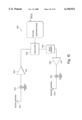
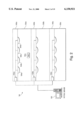
- FIG. 1 shows an overview of a system configured according to the invention.
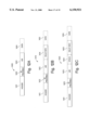
- FIG. 2 shows several cell controllers deployed in a multi-story building.
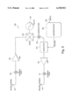
- FIG. 3 is a block diagram of a tag RF design according to the invention.
- FIG. 4 is a block diagram of an alternative embodiment of a tag.
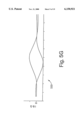
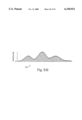
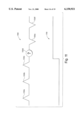
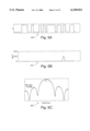
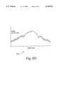
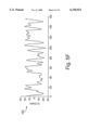
- FIGS. 5A-5H are diagrams of a signal as it passes through various stages of the system.
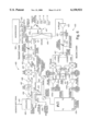
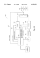
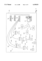
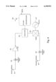
- FIG. 6 is a block diagram of the cell controller RF design.
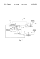
- FIG. 7 is a block diagram of a cell controller active antenna module.
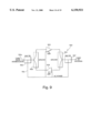
- FIG. 8 is a block diagram of a modulator RF design.
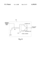
- FIG. 9 is a block diagram of a cell controller cable extender module.
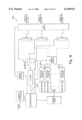
- FIG. 10 is a block diagram of a cell controller.
- FIG. 11 illustrates extraction of tag data from a series of correlations.
- FIGS. 12A-C are diagrams of tag datagrams.
- FIG. 13 shows a tag incorporating a delay element.
- FIG. 14 shows several cell controller receive chains operating in parallel.
- an article tracking system 100 contains the following general components:
- Tags Inexpensive miniature radio frequency transponding tags 101a-c are attached to people and/or items being tracked. Tags 101a-c "wake up” periodically, and “chirp” (transmit) a radio-coded unique identity code (UID).
- the tags 101a-c are designed so that their range is 15-30 meters in a typical indoor environment, the range mostly being limited by a need to conserve the life of the tag battery, and the requirement that the tag 101a and tag battery be small and thin.
- Cell controllers 102a-c detect the chirps of tags 101a-c and calculate the distances of those tags 101a-c to active antenna modules 104a-d connected to the cell controllers 102a-c.
- Each antenna module preferably has a transmit antenna and a receive antenna.
- a cell controller 102a is typically contained in a case and is mounted behind a hung ceiling.
- the cell controller 102a can receive power from a conventional wall outlet or the equivalent.
- the cell controller 102a is attached through coaxial cables 103a-d to the antenna modules 104a-d, respectively, which provide coverage of an area of the indoor facility 110.
- a tag signal 107, transmitted by a tag 101a, is received by one or more antenna modules 104a-d, and is processed by chips in the cell controller 102a, such as digital signal processing (DSP) chips.
- DSP digital signal processing
- the information resulting from this processing is used to identify both the identity of the transmitting tag 101a and the distance between the tag 101a and each, for example, of the receiving antenna modules 104a-d.
- Cell controllers 102a-c are in data communication with a host computer 105, which collects data and information available from the cell controllers 102a-c and archives the data into an open format database, such as an SQL Server.
- a host computer 105 which collects data and information available from the cell controllers 102a-c and archives the data into an open format database, such as an SQL Server.
- client workstations 120a-c communicate with the host computer 105 over a network, such as a LAN 115.
- a client application running on each of the client workstations 120a-c can access the SQL Server and presents the data in a way that is useful to an end-user.
- the tag 101a does not generate its own radio signal. Rather, an antenna module, for example antenna module 104a, continuously transmits a direct sequence spread spectrum interrogator signal 106 at a first frequency, for example 2440-megahertz.
- the tag 101a receives this signal 106, modulates its UID code onto the signal 106, and immediately transmits back a frequency-shifted signal 107 at, for example, 5780-megahertz to, for example, antenna 104a.
- the distance from the antenna module 104a to the tag 101a can then be determined by the cell controller 102a from the round trip time of transmission, accounting for fixed and known delays in the wiring and electronics.
- the cell controller 102a can quickly switch among antenna modules 104a-d to obtain the distance from the tag 101a to each of antenna modules 104a-d (which receive the return signal 107), and from that information determines the tag's location by triangulation techniques.
- the system 100 is designed to be scaleable, allowing addition of cell controllers to existing cell controllers 102a-c and antenna modules to existing antennas modules 104a-d to improve the precision with which tag location is determined.
- FIG. 2 shows how a collection of cell controllers 102a-c can be deployed in the large multistory building 110.
- multiple cell controllers 102a-c feed data to a single host computer 105, typically through a TCP/IP communications network.
- TCP/IP is not required for system operation, and a variety of data protocols and transfer mechanisms can be used. For example, if a local area network is not available, connection to the host can be accomplished via RS485, RS232, RS422, power line modem, or a dedicated phone line. Alternatively, specialized modems designed for use on such cables can be employed.
- Each of the cell controllers 102a-c can be installed to cover a separate floor 130a-c, respectively, with the exact configuration being modifiable by a system administrator.
- floor 130a cell controller 102a, with its collection of antenna modules 104a-d, is installed in the ceiling 140a.
- Antenna modules 104a-d are designed to provide good gain downwardly and horizontally, and poor gain upwardly, so that a vertical location (that is, the floor) of a tag 101a can be determined by noting which antenna modules 104a-d receive the strongest signals from the tag 101a.
- a ground plane is placed behind each antenna to reflect signals downward.
- the horizontal location of a tag 101a is then roughly determined by noting which antenna modules 104a-d receive a strong signal from the tag 101a.
- the horizontal location of the tag 101a with respect to an antenna module 104a can be determined more precisely by estimating the distance from the tag 101a to each antenna module 104a-d, based on the combined time of flight of the interrogation signal 106 and the tag signal 107.
- Each "cell,” consisting of a cell controller 102a and its antenna modules 104a-d, covers several thousand square feet of floor space. Each cell operates independently, enabling more cells to be added without affecting the performance of existing cells.
- one antenna per zone can be installed. Users wishing to track one or more tags 101a-c moving down hallways, can install antenna modules 104a-d every 20 or so meters along a hallway 130a-c, and calculate the linear location of a tag 101a by measuring the distance from the tag 101a to those antenna modules 104a-d. Users wishing to triangulate upon the location of a tag 101a must install enough antenna modules such that the tag 101a will be in range of at least three of the antenna modules. A typical installation will cover a complete facility 110 with a combination of "zone” and "hallway” coverage at a relatively low cost per square foot, and, over time, upgrade certain areas with enough antenna modules to triangulate upon a tag's position.
- a tag RF circuitry 300 receives signal 106 at a tag receive antenna 301 and transmits tag signal 107 at a tag transmit antenna 312.
- the function of the tag RF circuitry 300 is to transpond the incoming spread spectrum signal 106 by frequency translation.
- the secondary function of the tag RF circuitry 300 is to modulate tag data onto the emitted tag signal 107, under the control of a microprocessor 308.
- the information emitted on the tag signal 107 includes, in a preferred embodiment of the invention, the serial number of the tag, datagram headers, and tag data 309 such as that derived from a motion indicator or a low power indicator.
- the incoming signal 106 is preferably a direct sequence spread spectrum signal, biphase or quadrature modulated from the cell controller 102a, in the 2440 megahertz band.
- the signal 106 is received by the tag receive antenna 301, which collects the signal 106 and feeds it into the tag RF circuitry 300.
- an Rx (receive) bandpass filter 302 ensures that the tag is receiving signals only in the 2440 megahertz ISM band, rejecting radar signals, electronic newsgathering signals, and the like.
- the filter 302 is implemented as an etched coupled stripline filter embedded in the circuit board.
- the signal 106 is then amplified by an amplifier 303 to ensure that the received signal can be mixed, in a frequency mixer 304, without degrading the signal to noise ratio (SNR).
- SNR signal to noise ratio
- the frequency mixer 304 translates or shifts the carrier frequency from 2440 megahertz to 5780 megahertz.
- the incoming signal with a center frequency of 2440 megahertz, is mixed with the output of a phase locked oscillator (PLO) 305 with a center frequency of 3340 megahertz.
- PLO phase locked oscillator
- the PLO 305 consists of a phase locked loop (PLL) chip with three inputs: (1) a sampled output from a voltage controlled oscillator (VCO); (2) a reference tone from a 10 megahertz oscillator; and (3) a frequency programming interface to a microprocessor 308.
- the PLO 305 outputs a 1670-megahertz tone, which is then doubled to give the desired 3340-megahertz result.
- the next element of the tag RF circuitry 300 is a biphase modulator 307 which, under control of the microprocessor 308, can either pass the 5780-megahertz signal unaltered, or change the phase of the signal by 180 degrees.
- the modulator 307 is implemented as a single pole double throw RF switch 801 that feeds a 180 degree hybrid, as shown in FIG. 8.
- Several forms of modulation can be used, including on-off keyed (OOK) modulation, binary phase-shift keyed (BPSK) modulation, multiple phase-shift keyed (MPK) modulation, and quadrature amplified (QAM) modulation.
- BPSK is the preferred form of modulation.
- the output from the modulator 307 is fed into an amplifier 310, then is filtered by a transmitter bandpass filter 311, and the output of filter 311 is emitted from a transmit antenna 312 as the tag signal 107. Since the amplifier 310 operates at high frequency, it consumes significant power, and alternative embodiments (such as that shown in FIG. 4) that make this amplifier 310 unnecessary are preferred.
- the Tx Filter 311, implemented as a 5-pole filter, is necessary to ensure tag compliance with FCC Part 15 requirements.
- the tag RF circuitry 300 shown in FIG. 3 is intended to illustrate the general functions of a tag 101a-c, with an embodiment that is workable and self-explanatory. Those skilled in the art will be able to combine multiple functions into single elements in order to conserve power and take full advantage of available parts, or implement the same functions with a custom ASIC.
- FIG. 4 shows an alternative embodiment 400 which fulfills the same basic functions as that shown in FIG. 3, but with fewer components and using less power.
- the essential difference between the circuitry 400 shown in FIG. 4 and the circuitry 300 shown in FIG. 3 is that the modulator 404 in FIG. 4 is placed before the frequency mixer 406 in order to reduce the number of components (for example, the amplifier 310 is eliminated) and to conserve power.
- a tag such as the tag 101a, can transpond using backscatter, frequency translation by mixing, frequency translation by taking a harmonic, frequency translation by taking a subharmonic, or by signal delay (such as via a SAW device).
- transmit antenna 409 and receive antenna 401 are combined into a single element, and which uses a diplexer with the single antenna structure.
- tags 101a-c are powered depending on the application. (Note that FIGS. 3 and 4 omit the tag power source.)
- a tag 101a will be battery powered, with the RF stage turned on and off under control of the microprocessor 405.
- the microprocessor 405 goes into a low power state, where it merely waits until it is time to power up the tag 101a again.
- all tag circuitry 400 cycles on and off under analog control, using an RC time constant in the circuit 400 as the timing source.
- tag 101a Using the tag RF circuitry 300 or 400 of FIGS. 3 or 4, if a tag 101a is in range of two of the cell controllers 102a-c, and those cell controllers are sending pseudonoise with low cross correlation characteristics, the tag 101a will correctly transpond both signals simultaneously.
- Tags 101a-c require a period of time, on the order of a millisecond, to charge up and charge down. During these brief periods, typically, the tags 101a-c will not be stable enough to use, but will nonetheless emit RF into the radio channel through the transmit antenna 409. For high-performance applications, where radio bandwidth is limited, a microprocessor-controlled switch can be added to the tag's transmit chain to eliminate such spurious emissions.
- the tag RF circuitry 300, 400 shown in FIGS. 3 and 4 can be used in conjunction with different pairs of frequencies.
- the general approach described above works for any two allowable FCC spread spectrum bands. For example, the following combinations are permissible for license-free radio under FCC regulation Part 15.247:
- Spread spectrum operation is not required; two licensed narrow bands can be used. However, spread spectrum operation in the 2440 and 5780 megahertz bands is assumed for the remainder of the discussion.
- the tag RF circuitry 300, 400 shown in FIGS. 3 and 4 use frequency division multiple access, i.e., the tag circuitry 300, 400 receives and emits signals on different frequencies.
- An alternative embodiment 1500 uses time division multiple access, as shown in FIG. 13.
- the tag circuitry 1500 shown in FIG. 13 takes as an input at a receive antenna 1501 a signal at one frequency, such as 915 mHz, and emits the same signal through a transmit antenna 1508 at the same frequency after a delay of a microsecond.
- a cell controller such as cell controller 102a, transmits an interrogation signal 106 in bursts every 2 microseconds.
- a tag such as tag 101a, takes this signal as an input through the receive antenna 1501.
- the signal then passes through elements 1502-1504, as in FIGS. 3 and 4.
- a time delay element 1505 is then used to delay for a microsecond.
- the signal then passes through a transmit bandpass filter 1507 and is emitted from the transmit antenna.
- a SAW device can be used as the time delay element 1505.
- the cell controller ceases transmission, and reflections of the interrogation signal 106 in the environment die down to a minimal level.
- This half-duplex approach allows single frequency operation, although with lower bandwidth than with a full-duplex frequency shifting approach.
- the delay-based tag is capable of modulating the response signal by a 180-degree phase shift.
- the tag design 1500 shown in FIG. 13 is similar to those shown in FIGS. 3 and 4.
- FIG. 6 shows the radio stage of a cell controller 102a.
- the architecture of an antenna module, such as the antenna module 104, is shown in FIG. 7.
- the cell controller 102a and its remote antenna modules 104a-d modulate a baseband square wave input onto a 2440-megahertz carrier, filter the resulting 2440 megahertz signal to comply with FCC transmission requirements, transmit that filtered 2440-megahertz signal through a selected antenna module, receive a returning 5780-megahertz tag response through the same antenna module, extract the I (Inphase) and Q (Quadrature) components of the demodulated baseband signal, and digitize the result for subsequent processing.
- I Inphase
- Q Quadrature
- FIG. 10 shows the main components of the cell controller digital subsystem 650.
- the digital subsystem 650 provides a baseband input signal 601, and some number of nanoseconds later receives a demodulated response 107 from a tag 102a.
- the microprocessor 100 can change the behavior of the radio system by (a) modifying the baseband input signal 601; (b) modifying the chip rate, pseudonoise sequence length, and/or the pseudonoise sequence code; (c) modifying the transmit frequency 610 of radio transmitter 1002 and the receive frequency of radio receiver 1003 within a narrow range; (d) modifying the transmit gain of radio transmitter 1002 and the receive gain of radio receiver 1003; and (e) by switching antenna modules 104a-d.
- the demodulated response 107 from the tag 102a is split into I (Inphase) and Q (Quadrature) components by the receiver Radio 1003, and digitized by a digitizer 636.
- An integer DSP processor 1004 for example a TMS 320C54, reduces the output from the digitizer 636, performing correlation operations at high speed. If binary phase-shift keyed (BPSK) modulation is used on the transmitting side, the I and Q channels are correlated separately and combined. For quadrature phase-shift keyed (QPSK) modulation, each channel must be correlated twice, once with each sequence.
- BPSK binary phase-shift keyed
- QPSK quadrature phase-shift keyed
- the correlated data from the integer DSP 1004 is processed by a microprocessor 1001, such as a Pentium processor.
- a less powerful x86 processor, and a floating point DSP processor such as a TMS 320C30 can be used. Communications between the microprocessor 1001 and the host computer 105 is accomplished using a TCP/IP protocol, with Ethernet being preferred.
- the data that is input to the transmit chain is a baseband input signal 601 which is a pseudonoise spreading sequence.
- the length of the sequence and the code encoded in the sequence are set by a cell controller microprocessor 1001, and can be varied depending on signal processing requirements. Thirty-one or 127 bit sequences are typical, giving about 15 dB and 20 dB of compression gain, respectively.
- the 2440 megahertz and 5780 megahertz bands can support a 40 megahertz baseband input signal 601, and the cell controller 102a is designed to enable this full bandwidth to be utilized.
- FIGS. 5A-5G show an interrogation signal 106 as it passes through various stages of the cell controller RF circuitry 600.
- FIG. 5A shows a square wave baseband input to the modulator 500.
- FIG. 5B shows this baseband input digitally correlated 510.
- FIG. 5C shows an output 520 from a modulator 602, viewed through a spectrum analyzer centered at 2440 megahertz.
- FIG. 5D shows a spectrum analyzer view 530 of the tag signal 107, centered at 5780 megahertz.
- FIG. 5E shows the demodulated response from tag 107, separated into its I (Inphase) 545 and Q (Quadrature) 540 components.
- FIG. 5F shows the I and Q components, digitally correlated 550.
- FIG. 5G shows the negative of the second derivative of the correlated waveform, combinging the I and Q components 560.
- the modulator 602 (FIG. 6) modulates the baseband input 601 onto a 2440 megahertz carrier.
- Various forms of modulation are available and well-known to those skilled in the art.
- the modulator 602 is implemented as a single pole double throw RF switch 801 that feeds a 180-degree hybrid combiner 803, as shown in FIG. 8.
- the modulator 602 is preferably implemented as a QPSK modulator, which duplicates the BPSK modulator with one channel offset by 90 degrees from the other, each channel driven by a different baseband sequence with acceptable cross-correlation characteristics. Higher order modulation is also possible.
- Modulation by the modulator 602 results in sidelobes extending for hundreds of megahertz, which need to be filtered to comply with FCC requirements.
- the 2440-megahertz band has an adjacent band, which imposes very strong filtering requirements, best addressed using in the illustrated embodiment using a SAW filter 607 that combines wide passbands with tight stopbands.
- a wider passband supports a faster chipping rate in the baseband input signal 601, but a narrower passband provides an opportunity to use a wider range of frequency diversity to avoid jammers and/or support advanced signal processing techniques.
- the modulator 602 must operate at the same frequency as the available IF filter 607, typically in the range of 200 megahertz to 400 megahertz.
- a preamplifier 606 is necessary prior to the SAW IF filter 607, and the output of the filter needs to be amplified by an amplifier 608.
- a transmit IF oscillator 605 like all other RF oscillators in the cell controller circuitry 600, is phase locked to a 10 megahertz crystal source 603, which is distributed through a filter and splitter network 604 to each of the oscillators.
- the 10 megahertz source 603 needs to be within a few kilohertz of the 10 megahertz sources on the tags to avoid excessive baseband phase shift.
- the output from the IF filter 607 (from amplifier 608) is then mixed by a mixer 609 with the output from a phase locked oscillator (PLO) 611 and is converted to a carrier frequency of 2440 megahertz.
- the frequency of the PLO 611 can be modified within a narrow range under microprocessor control 610, in order to provide the frequency diversity needed to avoid jammers and/or for various advanced signal processing techniques.
- the degree of frequency diversity available is related to the specifications of the IF filter 607, with narrower filters permitting a slower chip rate but having more frequency flexibility.
- a filter typically needed to remove undesirable harmonic and difference frequencies from the output of the mixer 609.
- a driver amplifier 612 which raises the power level of the signal 106, so that it can be driven down the cable 103a to the remote antenna module 104a, and which buffers the output of the mixer 609 for a bandpass filter 613.
- the RF bandpass filter 613 is needed to remove FCC non-compliant outputs from the mixer 609.
- a directional coupler 616 provides a port to examine the signal 106 before it is transmitted to the remote antenna modules, for example antenna modules 104a-d.
- An attenuator 614 under microprocessor control 615 allows the signal processing software to decrease output power when a tag 101a-d is known to be nearby. This is helpful in circumstances when a nearby tag is known to be over-driven by the cell controller, and/or the signal processing software needs the tag to operate in a more linear range.
- the signal is then fed into a diplexer 618, which combines the transmitted 106 and received 107 signals onto a single wire.
- the diplexer 618 is a highpass/lowpass filter combination 619a that attenuates a received signal 107 relative to the transmit side and attenuates the transmit signal 106 relative to the receive side. Because of the presence of the Tx and Rx bandpass filters 613, 624, the specifications of the diplexer 618 are not very stringent.
- the cell controller RF stage 600 shown in FIG. 6 supports one remote antenna module 104a-d at a time.
- the system needs a switch 619, which enables a microprocessor control 620 to rapidly switch from one antenna to the next.
- the switch 619 takes RF and passes it into one of n cables, where n is, for example either 8 or 16.
- the switch 619 also provides DC power to the selected line.
- the RF signal is coupled into the cables with a capacitor (not shown), which provides DC isolation, and the DC power is coupled into the cables with RF chokes to provide RF isolation.
- the DC and RF travel together through a single coaxial cable to the selected antenna.
- the rise time of the DC in an antenna is in the range of 100 microseconds, limited by the effective resistance of the circuitry in and characteristics of the antenna and the capacitors needed for operation. To provide antenna switching time in the microsecond range, the DC power to an antenna is preloaded before the RF is switched.
- the combined DC and RF signal arrive through a coaxial cable, such as the cable 103a from the cell controller 102a.
- a bias tee 701 separates the RF signal 710 from the DC signal 712.
- the DC signal 712 is sent to Tx/Rx power control logic 702 which, in the simplest embodiment is a filter to remove noise from the line and provide a clean 5 volt power source.
- the RF output 710 from the bias tee 701 is fed into a diplexer 715, which is identical to the diplexer 618 in the cell controller 102a. This is then amplified by an amplifier 703 to the power level allowed by the FCC, and filtered by a filter 704 to remove line and amplifier noise in compliance with FCC regulations.
- the resulting signal is then sent to a transmit antenna 705.
- the transmit antenna 705 and receive antenna 706 are, in this embodiment, patch arrays, providing reduced energy in the vertical direction and spreading energy laterally, so that power is not wasted in the floor and ceiling, and so that minimal power is radiated upward.
- the 5780-megahertz response 107 from the tag 101a is filtered by a filter 707, amplified by an amplifier 708, and sent back down the cable 103a to the cell controller 102a.
- the system is designed to use cables 103a-d of a standard length, for example, 20 meters.
- a cable extender module 900 connects two lengths of cable and supports an extended cable length. Referring to FIG. 9, the elements of the module 900 use the DC power 910 from the cable 103 to drive low noise amplifiers 903, 904, which provide enough gain to drive the next section of cable.
- Bias tees 906, 907 separate the DC power 910 from the RF signals, and diplexers 908, 909 operate to separate the transmit signal 106 from the receive signal 107.
- the signal returning from the antenna module 104a to the cell controller 102a passes through the switch elements 621, 619 and diplexer 618 to the cell controller receive RF chain 622.
- the signal passes through a combination of a preamplifier 623 and bandpass filter 624, the exact arrangement of which varies based on the parts selected.
- a digitally controlled receive attenuator 625 under microprocessor control 626 is used to avoid saturating the receive chain when the tag 101a is known to be nearby. This is necessary to avoid losing the relationship between the I and Q components of the received signal 107, necessary for proper correlation and other signal processing.
- the signal then enters an I-Q zero IF demodulator circuitry 627-633.
- the microprocessor Rx frequency control 635 must be set in tandem with its counterpart in the transmit chain.
- the resulting signal is fed into a digitizer 636 (FIG. 10) in preparation for digital signal processing.
- the embodiment described above is simplified, based on an assumption that the cell controller can send and receive from only one antenna at a given time. Improved performance can be achieved by selecting send and receive antennas independently of each other.
- Software in the cell controller determines which antenna module receives the best signal from the tag. For example, if a particular tag, such as tag 101a, is close to an antenna, such as antenna 104a, then the antenna 104 will receive a strong signal from the tag 101a.
- the cell controller 102a can then transmit a signal, such as signal 106, from antenna 104a, and receive the transponded response 107 at antennas 104b, 104c, and 104d in turn. This can result in a stronger signal received at the antennas 104b-d, compared to the signal the antennas 104b-d would have received had the signal 106 been transmitted and the signal 107 received from each of the antenna modules 104b-d independently.
- the design 1600 shown in FIG. 14 provides multiple receive chains 1610a-1610n operating in parallel.
- Each of the receive chains 1610a-1610n includes an IQ demodulator, a digitizer, and a correlating element, shown as integer DSPs, for example, integer DSP 1620.
- integer DSPs for example, integer DSP 1620.
- Implementing each receive chain on a separate card provides scaleability.
- the use of multiple receive antenna modules for the same transmitted signal allows the cell controller signal processing software to employ spatial processing techniques to isolate multipath effects. These techniques take advantage of the fact that the multipath-corrupted response will have different characteristics at each antenna.
- FIG. 11 shows how tag data is extracted from a series of correlations. In the left half of the chart 1110 shown in FIG. 111, the tag is transmitting a "zero.” This is accomplished by setting the tag's modulator 307 to pass the interrogator signal 106 unaltered.
- Pseudonoise sequences can be varied under microprocessor control at the cell controller. When a tag's presence is first detected, relatively short sequences must be used, as shown in FIG. 11. Once the tag's bit timing is ascertained, it is possible to use longer sequences for improved SNR, which is helpful in distance measurement.
- Each tag is a stand-alone unit that is unaware in any way of the outside world.
- Each tag has a Unique Identifying Code (UID) associated with the tag when it is manufactured.
- a tag wakes up periodically and, for a short period of time, converts any incoming 2440-megahertz signal 106 to an outgoing 5780-megahertz signal 107, while modulating its UID and other data onto the outgoing signal 107 which it chirps (transmits).
- the tag does not communicate with other tags.
- the tag does not explicitly respond to an interrogation signal, but merely transponds any incoming signal 106 in the 2440-megahertz band, which may or may not include a pseudonoise sequence from a nearby cell controller antenna module 104a. This approach greatly simplifies the design and fabrication of the tag 101a.
- tags "wake up" and chirp their UIDs at randomized times, which can be calculated (by both the tag and the cell controller) based on a pseudorandom number generator which incorporates the tag's UID. For example, for a tag which chirps approximately every 5 seconds, the tag generates pseudorandom numbers between 0.0 and 2.0, and adds these to a 4.0-second minimum delay time, resulting in a sequence of delay times uniformly distributed between 4.0 and 6.0 seconds.
- a typical pseudorandom number generator has the form:
- the resulting N is used as the seed for the next pseudorandom number in the pseudorandom number sequence.
- a pseudorandom number generator of this kind it is possible that two tags will use the same seed, resulting in their tag signals repetitively colliding. Further, with small differences in tag clocks, all pairs of tags will eventually drift through this synchronized state for some amount of time. To avoid these conditions it is desirable to incorporate each tag's UID, as noted above, into the delay time for that tag, resulting in a different pseudorandom sequence for each tag, that is:
- N Xor(Delay, BitRotate(UID, And(N,1111 2 )).
- one embodiment of the tag datagram 1400 contains a header 1401 to enable the cell controller to detect the tag's presence, followed by an identifier preamble 1402, followed by the tag's UID 1403.
- the header 1401 can be of zero length.
- the identifier preamble 1402 can be implemented, for example, as a validity check such as a cyclic redundancy check (CRC). Given a sufficiently simple Delay function and high clock stability, the cell controller can infer the tag's chirping sequence by noting the timing of a series of chirps of the datagram 1400.
- CRC cyclic redundancy check
- the tag adds Delay information 1414, thus enabling the cell controller to forecast the transmission time of the tag's next and subsequent chirps of the datagram 1410.
- this information would include the data: Delay and And(N,1111 2 ) .
- a shorter header is used than in the datagrams 1400, 1410 of FIGS. 12a and 12b, such that the cell controller is not guaranteed to have enough time to detect the tag's presence before the UID 1423 contained in the tag datagram 1420 is transmitted.
- Appended to the datagram 1420 is the transmission delay 1425 of the next chirp, enabling the cell controller to anticipate the time that the tag will next chirp its datagram 1420, even if the cell controller does not have enough time to identify the identity of the tag from the first received chirp of the datagram 1420. The cell controller can then anticipate this next chirp and ascertain the identity of the tag at that time.
- the cell controller can duplicate the tag's pseudorandom number generator to calculate the times of all future chirps by the tag.
- a series of special synchronization bits 1424 are inserted between the UID 1423 and the delay information 1425, to reliably determine when the UID 1423 ends; in this case, the UID 1423 must be defined so that it does not include the synchronization sequence or its inverse.
- FIGS. 12a, 12b, and 12c include optional data sections 1404, 1415, 1426, which allow a tag to transmit data to the cell controller.
- These sections 1404, 1415, 1426 can include data from within the tag, such as from a motion detector or a low power indicator, or from an external device attached to the tag, such as metabolic information for medical telemetry if the tag is attached to a person.
- This identifier preamble enables the cell controller to quickly verify that a tag is chirping as expected, without needing to decode the tag's complete UID. This frees the cell controller for other activities, such as communicating with different tags in proximity to other antennas.
- the identifier preamble 1402, 1412, 1422 and tag UIDs 1403, 1413, 1423 are set externally, and if appropriate can be defined to include error correction bits.
- the UID of a tag may be hardcoded into the tag (e.g., as a serial number).
- Tags may be grouped based on their UIDs, and different groups may be associated with different cell controllers. Each cell controller contains information (received from another source) about which tags are in the group associated with the cell controller.
- the cell controller can extract the UID information from the tag signal to determine whether the tag signal was sent by a tag in the group associated with the cell controller.
- the delay information fields 1414, 1425 and data fields 1404, 1415, 1426 can also include error correction bits.
- data can be reduced to a stream of half-bytes.
- the tag can look up the half-byte's value in a table which contains, for example, 8-bit values, which represent the value of the half-byte plus error correction information.
- a single cell controller can handle all three types of datagrams 1400, 1410, 1420 shown in FIGS. 12a-c. The choice of datagram type would depend on the application requirements for a particular tag.
- the amount of time it takes for a cell controller to detect the presence of a tag may vary depending on the nature of the cell controller design. For example, a 100-microsecond time to switch antennas may be significant when the cell controller is cycling among 16 antennas.
- the tag datagram header In order to be assured that a tag will be identified the first time its tag signal is received by the cell controller, the tag datagram header must be long enough to give the cell controller time to try all of its antennas. If the performance requirement is in the range of 100 tags per second, 2 or 3 extra milliseconds in the header can be tolerated. But for higher performance requirements, or when tag power consumption must be minimized, it is necessary to either improve the performance of the cell controller or to use a tag datagram 1420 of the type shown in FIG. 12c.
- the cell controller can collect tag information from a variety of antennas in an organized way, in order to better calculate tag location by using antenna and/or frequency diversity. If a tag is responding exactly when it is expected to respond, it is not necessary for a cell controller to detect every bit transmitted in the tag datagram in order to be reasonably certain that it is receiving a signal from the correct tag. A correct identifier preamble arriving exactly on schedule is almost certain to be from the expected tag. This provides an opportunity for the cell controller to try a variety of antennas that may or may not be able to communicate with the tag.
- the tag can be configured to send shorter transmissions more frequently. For example, if a tag is configured to chirp its datagram on average every 10 seconds, it may also be configured to transmit a much shorter code more frequently, such as every half-second. This shorter code might be as short as one bit long, and take just a few microseconds to transmit. Thus, even hundreds of such transmissions per second would consume only a small percentage of the communication channel.
- the cell controller can anticipate the exact timing of each such transmission, thus matching each signal with the originating tag based on the time of the transmission. Error correction codes can be arranged such that long chirps from one tag will not typically be corrupted by quick chirps from other tags. The cell controller has the data to forecast most of such collisions.
- the cell controller has a means for sending information and instructions to the tag during the times that the tag is known by the cell controller to be in operation. Such instructions can include commands to be passed on to a device attached to the tag.
- the cell controller is capable of downloading such information, most simply by on-off keying, or for more advanced tags by flipping the pseudonoise bit sequences to indicate one or zero.
- the downlink (downloading) approach is driven by tag cost and feature requirements, with higher bit downlink transmission rates requiring more expensive receivers that consume more power.
- a single cell controller can support read-only tags, read/write tags, and high-speed read/write tags simultaneously, with the cell controller adapting its behavior depending on the features supported in a particular tag.
- Timing of transmission from tag to cell controller depends on the item being tagged. Inventory and equipment can be set to transmit relatively infrequently, such as once per minute. More frequent transmissions would be required, for example, for tags on people in a secure facility. For read/write versions of tags, timing of transmission could be modified on command from the cell controller.
- Alternative tag designs enable variation in transmission time based on environmental factors. For example, motion detectors may be placed in a tag to decrease the time between transmissions when the tag is in motion. As another example, a tag might transmit more frequently and with higher power when the tag has been tampered with. As another example, a tag might incorporate a slightly modified Electronic Article Surveillance (EAS) device, which would cause the tag to transmit its UID more frequently when in range of a standard EAS detector. More generally, if a tag is attached to another electronic device, transmission interval can be modified under the control of that device.
- EAS Electronic Article Surveillance
- Tags 101a-c transmit a low RF power level in order to increase their portability and lifespan.
- tag signal transmissions 107 are designed to be only a few milliseconds in duration. Therefore, even if a tag transponds its UID every few seconds, careful tag design allows the battery life of the tag to approximate the shelf life of the battery itself. For even lower power usage, a motion detector can be incorporated into the tag so that, for example, transmissions can be less frequent when the tag is stationary.
- battery replacement may be accomplished by incorporating the battery in an attachment mechanism.
- re-usable tag electronics may be attached to a disposable patient bracelet, with the battery included in the bracelet.
- a battery may be incorporated into the clip of an ID bracelet. More generally, a battery may be incorporated into an inexpensive disposable portion of an active RFID tag, with the electronics in the other, more expensive, portion.
- the tag could tap into that power source. This approach is most practical in situations where the tag can be designed into the equipment itself (such as a handheld computer), or where the equipment and power source are large (such as a forklift). A larger power source allows for longer tag range.
- a tag signal 107 is received at a time that is the sum of (1) known fixed delays in the cell controller 102a that transmitted the interrogator signal 106, due to its circuitry and the wiring to and from its antenna modules 104a-d, (2) fixed time delays in the antenna module 104a and tag 101a, and (3) the time for the interrogator signal 106 and tag signal 107 to travel through the air.
- the travel time of the interrogator signal 106 and tag signal 107 through the air The duration of the pseudonoise sequence modulated onto the 2440 MHz carrier signal 106 by the cell controller 102a must be greater than the combined travel time of the signal 106 and the tag signal 107.
- Techniques for correlating a pseudonoise sequence are well known in the art. In the absence of multipath effects, the cell controller 102a can derive a simple triangular correlation peak from the received tag signal 107, as shown in FIG. 5B. But in most indoor environments, the actual received tag signal looks more like that shown in FIGS. 5D-5G.
- a 40-megahertz chip rate results in a correlation peak with a rise time of 25 nanoseconds, corresponding to a rise time distance of about 25 feet. Since tag location is calculated using round-trip travel time, single-chip accuracy therefore allows tag distance to be calculated within about 12 feet, without any advanced signal processing.
- Approximate location of a tag can be calculated by noting when correlated signal-to-noise ratio rises above a predefined level. Improved accuracy can be achieved by trying a small variety of carrier frequencies and choosing the one that rises the earliest; such frequency diversity is supported by the radio system shown in FIGS. 4-6. This approach is sensitive to the system signal-to-noise ratio.
- MUSIC For highest accuracy, the MUSIC algorithm, known to those in this field, can be used, for which accuracy in the 0.01 chip range has been reported.
- MUSIC requires frequency diversity, which is supported by the radio system herein disclosed and shown in FIG. 6. The method is based on a decomposition of the eigenvector space of the pseudonoise correlation matrix of the delay profile data vector. Frequency diversity is required, where each distinct frequency provides the information to solve for an additional multipath component. For tags that are mostly stationary, necessary data can be collected and the calculation completed as a background process. For inventory applications, motion detectors can be incorporated into the tag, which would then inform the cell controllers whenever their locations need to be recalculated.
- Story-by-story discrimination in a building can be accomplished by mounting antennas in the ceiling that radiate downward (or antennas in the floor that radiate upward), as shown in FIG. 2.
- antennas mounted sideways on horizontal partitions can determine location relative to those partitions.
- Relatively narrow beamwidth antennas which are less sensitive to multipath effects, can be directed at doorways and the like.
- a cell controller antenna 104a can be mounted near a computer screen, with coverage corresponding to viewing angle of the screen. Software can then be arranged to automatically configure the operating system for the person in range, or to blank the screen for security purposes depending on who is or is not in range. Similar concepts can be used in conjunction with copying machines, microfilm readers, restricted equipment, and the like.
- a single antenna module can include three separate antennas placed in a triangle. By comparing phase difference using the Inphase and Quadrature components of the returning signal, an indication of the tag's angle can be determined. In high frequency embodiments, such as at 2.45 gigahertz, such antennas could be within inches of each other and be quite effective.
- Heuristic techniques can be used to analyze the correlation profile to estimate the time at which the correlation began, that is, the time at which the correlation peak begins to be distinguishable from the "noise" baseline.
- Frequency diversity can provide a variety of samples, the best of which can be chosen.
- Improved estimates can be achieved by pattern matching the correlation peak with one of a vocabulary of well-studied typical correlation profiles.
- tags can be placed at known fixed locations, and tags passing near those locations will likely demonstrate similar correlation profiles. Such fixed tags can also be utilized to detect the presence of jammers (objects which emit, intentionally or unintentionally, interfering signals) and to provide a real-time testbed for trying a variety of antijamming techniques.
- Antenna diversity is the most important tool for improving the accuracy of tag location calculation. If low accuracy is required, antennas can be placed so that only one or two antennas are in range of a given tag. In this case there is insufficient data for triangulation, and only enough information to detect tag presence and estimate tag distance from one or two antennas at any one time. Approximate bearing of a tag can be estimated from the signal strength of antennas designed for the purpose and well-known to those skilled in the art; with the caveat that such bearing tends to reflect the strongest signal received, which might include a substantial multipath component. Conversely, for areas requiring high accuracy, a diversity of relatively narrow beamwidth antennas can be installed, for example, at entrances, which together provide a clear picture of location.
- Antenna diversity also provides system scaleability.
- substantially omnidirectional and/or ceiling mounted antennas can be installed relatively far from each other, for a relatively low cost per square foot of coverage.
- a diversity of closely-spaced and/or directional antennas can provide high accuracy at an increased cost.
- Tags dispersed at the entrance of a secure facility can be tracked through that facility and a special code can be emitted when the tag is tampered with.
- the tag's code can be determined by monitoring the tag's response, the tag's transmission interval varies according to an algorithm that can be arranged to be known only to the tag and the host, and impossible to directly determine without destroying the tag.
- the tag may for example, include an element, such as a physical element, for reprogramming its code and transmission interval. For example, a photo ID with an incorporated tag might be reprogrammed each time the person wearing the photo ID passes a security checkpoint, potentially in conjunction with biometrics technology.
- each cell controller will be operating according to a search and data collection method, rapid movement between antennas, the pseudonoise code, the changing chipping rate, and so forth, will appear as random noise to another cell controller.
- codes with known cross-correlation characteristics such as Gold Codes, can be allocated to various cell controllers by the host computer, particularly the codes used to search for tags.
- cell controllers can switch choice of pseudonoise codes on a randomized basis.
- each cell controller reports the tag's distances from its antenna modules.
- the central host 105 assembles this data to calculate the tag's location.
- pseudonoise codes are available for use by a cell controller. Thus, if one code seems to be receiving interference from other users of the spectrum, the cell controller can choose another code.
- the tag being in essence a transponder, does not need to know the particular code being used. Likewise, center frequency can be adjusted somewhat if another user is causing difficulty.
Abstract
Description
N=rand(seed) Formula 1
Delay=f(N,UID) Formula 2
Delay=Xor(N, BitRotate(UID, AND(N, 1111.sub.2)) Formula 3
Claims (38)
Priority Applications (4)
| Application Number | Priority Date | Filing Date | Title |
|---|---|---|---|
| US08/953,755 US6150921A (en) | 1996-10-17 | 1997-10-17 | Article tracking system |
| US09/339,740 US6353406B1 (en) | 1996-10-17 | 1999-06-24 | Dual mode tracking system |
| US09/517,606 US6812824B1 (en) | 1996-10-17 | 2000-03-02 | Method and apparatus combining a tracking system and a wireless communication system |
| US09/522,128 US6483427B1 (en) | 1996-10-17 | 2000-03-09 | Article tracking system |
Applications Claiming Priority (4)
| Application Number | Priority Date | Filing Date | Title |
|---|---|---|---|
| US2865896P | 1996-10-17 | 1996-10-17 | |
| US4432197P | 1997-04-24 | 1997-04-24 | |
| US4424597P | 1997-04-24 | 1997-04-24 | |
| US08/953,755 US6150921A (en) | 1996-10-17 | 1997-10-17 | Article tracking system |
Related Child Applications (2)
| Application Number | Title | Priority Date | Filing Date |
|---|---|---|---|
| US24460099A Continuation-In-Part | 1996-10-17 | 1999-02-04 | |
| US09/522,128 Continuation US6483427B1 (en) | 1996-10-17 | 2000-03-09 | Article tracking system |
Publications (1)
| Publication Number | Publication Date |
|---|---|
| US6150921A true US6150921A (en) | 2000-11-21 |
Family
ID=27363316
Family Applications (2)
| Application Number | Title | Priority Date | Filing Date |
|---|---|---|---|
| US08/953,755 Expired - Lifetime US6150921A (en) | 1996-10-17 | 1997-10-17 | Article tracking system |
| US09/522,128 Expired - Lifetime US6483427B1 (en) | 1996-10-17 | 2000-03-09 | Article tracking system |
Family Applications After (1)
| Application Number | Title | Priority Date | Filing Date |
|---|---|---|---|
| US09/522,128 Expired - Lifetime US6483427B1 (en) | 1996-10-17 | 2000-03-09 | Article tracking system |
Country Status (8)
| Country | Link |
|---|---|
| US (2) | US6150921A (en) |
| EP (1) | EP0932840A1 (en) |
| JP (1) | JP3147306B2 (en) |
| KR (1) | KR20000049066A (en) |
| CN (1) | CN1233327A (en) |
| AU (1) | AU5426298A (en) |
| CA (1) | CA2268951A1 (en) |
| WO (1) | WO1998016849A1 (en) |
Cited By (285)
| Publication number | Priority date | Publication date | Assignee | Title |
|---|---|---|---|---|
| WO2001041032A1 (en) * | 1999-11-30 | 2001-06-07 | David Russell | Methods, systems, and apparatuses for secure interactions |
| US20010008390A1 (en) * | 2000-01-14 | 2001-07-19 | 3M Innovative Properties Company | User interface for portable rfid reader |
| US20010053949A1 (en) * | 2000-03-13 | 2001-12-20 | Robotic Vision Systems, Inc. | Secure tracking of articles |
| US20020027509A1 (en) * | 2000-09-01 | 2002-03-07 | Kouichi Tanokura | Object detection system |
| US6356230B1 (en) * | 1999-08-20 | 2002-03-12 | Micron Technology, Inc. | Interrogators, wireless communication systems, methods of operating an interrogator, methods of monitoring movement of a radio frequency identification device, methods of monitoring movement of a remote communication device and movement monitoring methods |
| US20020059535A1 (en) * | 2000-11-14 | 2002-05-16 | Bekritsky Benjamin J. | Wireless clock synchronization |
| US6393045B1 (en) * | 1997-09-26 | 2002-05-21 | Wherenet Corp. | Spread spectrum baseband modulation of magnetic fields for communications and proximity sensing |
| US20020090958A1 (en) * | 1999-03-09 | 2002-07-11 | Ovard David K. | Wireless communication systems, interrogators and methods of communication within a wireless communication system |
| US6424264B1 (en) * | 2000-10-12 | 2002-07-23 | Safetzone Technologies Corporation | System for real-time location of people in a fixed environment |
| US6424838B1 (en) * | 1998-06-02 | 2002-07-23 | Anatoli Stobbe | Process and configuration for detecting a transponder with reference to a particular cell of two adjacent overlapped cells |
| US20020111702A1 (en) * | 2001-02-15 | 2002-08-15 | Angel Jeffrey R. | Factory personnel monitors |
| US6448886B2 (en) | 1998-08-14 | 2002-09-10 | 3M Innovative Properties Company | Application for radio frequency identification systems |
| US6454708B1 (en) * | 1999-04-15 | 2002-09-24 | Nexan Limited | Portable remote patient telemonitoring system using a memory card or smart card |
| WO2002088776A2 (en) * | 2001-05-02 | 2002-11-07 | Rf Technologies, Inc. | Hybrid real time locating system and methodology |
| US20020175804A1 (en) * | 2001-05-22 | 2002-11-28 | Takeshi Saito | Interrogator and goods management system adopting the same |
| US20020190845A1 (en) * | 1999-08-09 | 2002-12-19 | Micron Technology, Inc. | RFID material tracking method and apparatus |
| WO2002103645A2 (en) * | 2001-06-14 | 2002-12-27 | Rf Code, Inc. | Wireless identification system and protocol |
| US20030030542A1 (en) * | 2001-08-10 | 2003-02-13 | Von Hoffmann Gerard | PDA security system |
| US6529164B1 (en) | 2000-03-31 | 2003-03-04 | Ge Medical Systems Information Technologies, Inc. | Object location monitoring within buildings |
| US6531963B1 (en) * | 2000-01-18 | 2003-03-11 | Jan Bengtsson | Method for monitoring the movements of individuals in and around buildings, rooms and the like |
| US6535125B2 (en) | 2000-08-22 | 2003-03-18 | Sam W. Trivett | Remote control locator system |
| US6547014B2 (en) | 2001-02-15 | 2003-04-15 | Ingersoll-Rand Company | Pneumatic tool housings having embedded electronic devices |
| US6556942B1 (en) * | 2000-09-29 | 2003-04-29 | Ut-Battelle, Llc | Short range spread-spectrum radiolocation system and method |
| US20030097302A1 (en) * | 2001-11-21 | 2003-05-22 | Overhultz Gary L. | Advertising compliance monitoring system |
| US6568483B2 (en) | 2001-02-07 | 2003-05-27 | Ingersoll-Rand Company | Interchangeable pistol grip handles for pneumatic tools and seals therefor |
| EP1316814A1 (en) * | 2001-11-30 | 2003-06-04 | Cross Point RFAPP B.V. i.o. | Tracing of transponder-tagged objects |
| US20030102367A1 (en) * | 2000-04-20 | 2003-06-05 | Francois Monette | Automated manufacturing control system |
| US20030120607A1 (en) * | 2001-12-20 | 2003-06-26 | Koninklijke Philips Electronics N.V. | E-receipt verification system and method |
| US6600418B2 (en) | 2000-12-12 | 2003-07-29 | 3M Innovative Properties Company | Object tracking and management system and method using radio-frequency identification tags |
| US6600420B2 (en) | 1998-08-14 | 2003-07-29 | 3M Innovative Properties Company | Application for a radio frequency identification system |
| US20030146835A1 (en) * | 2000-03-31 | 2003-08-07 | Ge Medical Systems Information Technologies, Inc. | Object location monitoring within buildings |
| US20030148812A1 (en) * | 2002-02-01 | 2003-08-07 | Paulsen Craig A. | Gaming system and gaming method |
| US20030162593A1 (en) * | 2002-02-27 | 2003-08-28 | Griswold Chauncey W. | Contactless card reading in a gaming machine |
| US20030174099A1 (en) * | 2002-01-09 | 2003-09-18 | Westvaco Corporation | Intelligent station using multiple RF antennae and inventory control system and method incorporating same |
| US6624752B2 (en) * | 1999-11-15 | 2003-09-23 | Bluetags A/S | Object detection system |
| US20030195825A1 (en) * | 1999-05-19 | 2003-10-16 | I.D. Systems, Inc. | System and method for managing remotely and distantly located assets |
| US20030198365A1 (en) * | 2000-05-16 | 2003-10-23 | The Upper Deck Company, Llc. | Apparatus for capturing an image |
| US20030199321A1 (en) * | 2002-04-22 | 2003-10-23 | Williams Richard C. | Gaming system allowing location determination of a gaming unit in a casino |
| US20030196312A1 (en) * | 2000-04-06 | 2003-10-23 | Ford Motor Company | Method for manufacturing an item |
| US6646554B1 (en) | 1998-06-08 | 2003-11-11 | 3M Innovative Properties Company | Identification tag with enhanced security |
| US20030209599A1 (en) * | 1995-04-13 | 2003-11-13 | Gatto James G. | Electronic fund transfer or transaction system |
| US20030225707A1 (en) * | 2002-01-09 | 2003-12-04 | Ehrman Kenneth S. | System and method for managing a remotely located asset |
| US6662068B1 (en) * | 2001-10-12 | 2003-12-09 | Touraj Ghaffari | Real time total asset visibility system |
| US20030229445A1 (en) * | 2002-05-13 | 2003-12-11 | The Charles Stark Draper Laboratory, Inc. | Low-cost, low-power geolocation system |
| US6669089B2 (en) | 2001-11-12 | 2003-12-30 | 3M Innovative Properties Co | Radio frequency identification systems for asset tracking |
| WO2004006051A2 (en) * | 2002-07-09 | 2004-01-15 | Dr Sawyer Fred Ph D | Method and apparatus for tracking objects and people |
| US20040023709A1 (en) * | 2002-08-05 | 2004-02-05 | Nicole Beaulieu | Gaming apparatus and gaming method |
| US20040036595A1 (en) * | 2002-08-07 | 2004-02-26 | Thomas Kenny | Object tracking |
| US6700493B1 (en) | 1996-12-02 | 2004-03-02 | William A. Robinson | Method, apparatus and system for tracking, locating and monitoring an object or individual |
| US20040043747A1 (en) * | 2002-06-04 | 2004-03-04 | Forster Ian J. | Reflective communication using radio-frequency devices |
| US6729956B2 (en) | 2002-01-18 | 2004-05-04 | Igt | Gaming apparatus with player tracking capabilities |
| US6738628B1 (en) * | 1999-09-03 | 2004-05-18 | International Business Machines Corporation | Electronic physical asset tracking |
| EP1421566A1 (en) * | 2001-04-03 | 2004-05-26 | United States Postal Service | Method and apparatus for tracking and locating a moveable article |
| US20040100377A1 (en) * | 2002-11-26 | 2004-05-27 | Ge Medical Systems Information Technologies, Inc. | Wireless subject locator |
| US20040102870A1 (en) * | 2002-11-26 | 2004-05-27 | Andersen Scott Paul | RFID enabled paper rolls and system and method for tracking inventory |
| US20040100361A1 (en) * | 2002-11-26 | 2004-05-27 | Ge Medical Systems Information Technologies, Inc. | Method and apparatus for identifying a subject |
| US20040107068A1 (en) * | 1999-11-24 | 2004-06-03 | Renishaw Plc | Motion detection and analysis |
| US6747562B2 (en) * | 2001-11-13 | 2004-06-08 | Safetzone Technologies Corporation | Identification tag for real-time location of people |
| US6784789B2 (en) * | 1999-07-08 | 2004-08-31 | Intermec Ip Corp. | Method and apparatus for verifying RFID tags |
| US20040169603A1 (en) * | 2003-02-28 | 2004-09-02 | Armbruster Peter J. | Location determination for mobile units |
| US6788199B2 (en) | 2001-03-12 | 2004-09-07 | Eureka Technology Partners, Llc | Article locator system |
| US6791451B1 (en) * | 2000-08-31 | 2004-09-14 | Christopher Russell Muise | System and method for improving the security of storage of firearms and other objects, and for aiding the recovery of such if removed from storage |
| US20040214534A1 (en) * | 2003-04-28 | 2004-10-28 | Motorola, Inc. | Antenna phase modulator |
| US6816075B2 (en) | 2001-02-21 | 2004-11-09 | 3M Innovative Properties Company | Evidence and property tracking for law enforcement |
| US6825766B2 (en) | 2001-12-21 | 2004-11-30 | Genei Industries, Inc. | Industrial data capture system including a choke point portal and tracking software for radio frequency identification of cargo |
| US20040264441A1 (en) * | 2003-06-30 | 2004-12-30 | Janne Jalkanen | RFID system with packetized data storage in a mobile environment: methods, systems and program products |
| US20050006466A1 (en) * | 2001-11-21 | 2005-01-13 | Overhultz Gary L. | Advertising compliance monitoring system |
| US20050029872A1 (en) * | 2003-08-08 | 2005-02-10 | Ehrman Kenneth S. | Universal power supply |
| US20050043072A1 (en) * | 2002-02-06 | 2005-02-24 | Igt | Control and configuration of gaming machines based on gaming machine location |
| KR100470769B1 (en) * | 2002-11-11 | 2005-03-11 | 주식회사 마이크로트랙 | Method and system for anti-collision between transponders |
| WO2005026993A1 (en) * | 2003-09-10 | 2005-03-24 | Agile Software Corporation | A system and method for managing item interchange and identification in an extended enterprise |
| US20050108089A1 (en) * | 1999-05-19 | 2005-05-19 | Ehrman Kenneth S. | Fully automated vehicle rental system |
| US20050110636A1 (en) * | 2001-10-12 | 2005-05-26 | Touraj Ghaffari | Real time total asset visibility system |
| US20050121526A1 (en) * | 2003-12-09 | 2005-06-09 | Intelleflex Corporation | Battery activation circuit |
| US20050159982A1 (en) * | 2003-07-17 | 2005-07-21 | Wayne Showalter | Laboratory instrumentation information management and control network |
| US20050200453A1 (en) * | 2004-01-27 | 2005-09-15 | Turner Richard H | Method and apparatus for detection and tracking of objects within a defined area |
| US20050200456A1 (en) * | 2004-03-11 | 2005-09-15 | Raj Bridgelall | Method and system for communicating data to a wireless access point |
| US20050205659A1 (en) * | 1999-05-17 | 2005-09-22 | Yuji Murayama | Information processing apparatus and method, information processing system, and medium |
| US6958677B1 (en) | 2000-03-31 | 2005-10-25 | Ge Medical Systems Information Technologies, Inc. | Object location monitoring system |
| US20050278044A1 (en) * | 2004-06-14 | 2005-12-15 | Yue Chen | Method and system for codec with polyringer |
| US20050285739A1 (en) * | 2004-06-25 | 2005-12-29 | Velhal Ravindra V | Proximity management system and method using radio-frequency identification tags |
| US20060022815A1 (en) * | 2004-07-30 | 2006-02-02 | Fischer Jeffrey H | Interference monitoring in an RFID system |
| US6996543B1 (en) * | 1998-04-14 | 2006-02-07 | International Business Machines Corporation | System for protection of goods against counterfeiting |
| US20060036838A1 (en) * | 2004-08-10 | 2006-02-16 | Salcedo David M | Security system network interface and security system incorporating the same |
| US20060036346A1 (en) * | 2002-11-26 | 2006-02-16 | Andersen Scott P | System and method for tracking inventory |
| US20060047961A1 (en) * | 2004-08-26 | 2006-03-02 | Fujitsu Limited | Wireless tag system, wireless tag access control device, wireless tag access control method, wireless tag access control program and wireless tag |
| US20060056325A1 (en) * | 1998-02-19 | 2006-03-16 | Wood Clifton W Jr | Method of addressing messages and communications system |
| US20060061481A1 (en) * | 2004-09-23 | 2006-03-23 | Kurple William M | Receptacle locator |
| US20060071757A1 (en) * | 2004-09-24 | 2006-04-06 | Burghard Brion J | Communication methods, systems, apparatus, and devices involving RF tag registration |
| US20060077036A1 (en) * | 2004-09-29 | 2006-04-13 | Roemerman Steven D | Interrogation system employing prior knowledge about an object to discern an identity thereof |
| US20060077043A1 (en) * | 2002-11-21 | 2006-04-13 | Koninlijke Philips Electronics N.V. | Method of recognizing whether a trasponder belongs to a group of transponders |
| US20060131405A1 (en) * | 2004-12-03 | 2006-06-22 | Checkpoint Systems, Inc. | Method and system for tracking items in a shipping facility |
| US20060168644A1 (en) * | 2000-02-29 | 2006-07-27 | Intermec Ip Corp. | RFID tag with embedded Internet address |
| US7084765B2 (en) * | 2001-07-12 | 2006-08-01 | Intel Corporation | Processor-based positioning system |
| US7098792B1 (en) | 2003-05-14 | 2006-08-29 | Rf Technologies, Inc. | Tamper proof system and method |
| US20060202033A1 (en) * | 2005-03-03 | 2006-09-14 | Campero Richard J | Apparatus for and method of using an intelligent network and RFID signal router |
| WO2006098790A1 (en) * | 2005-03-14 | 2006-09-21 | The Alfred E. Mann Foundation For Scientific Research | System and method for locating objects and communicating the same |
| US20060208891A1 (en) * | 2005-03-01 | 2006-09-21 | Ehrman Kenneth S | Mobile portal for rfid applications |
| US20060255131A1 (en) * | 2005-05-11 | 2006-11-16 | Intelleflex Corporation | Smart tag activation |
| US20060267735A1 (en) * | 1999-03-09 | 2006-11-30 | Ovard David K | Wireless communication systems, interrogators and methods of communicating within a wireless communication system |
| US20060279407A1 (en) * | 1999-03-09 | 2006-12-14 | Roy Greeff | Phase shifters, interrogators, methods of shifting a phase angle of a signal, and methods of operating an interrogator |
| US20070001809A1 (en) * | 2005-05-02 | 2007-01-04 | Intermec Ip Corp. | Method and system for reading objects having radio frequency identification (RFID) tags inside enclosures |
| US20070008108A1 (en) * | 2005-07-07 | 2007-01-11 | Schurig Alma K | Unsynchronized beacon location system and method |
| US20070008072A1 (en) * | 2005-06-15 | 2007-01-11 | Vijay Pillai | System and method for setting an oscillator in an RFID transponder |
| US20070012771A1 (en) * | 2005-07-15 | 2007-01-18 | Innovatier, Inc. | RFID bracelet and method for manufacturing a RFID bracelet |
| US20070018794A1 (en) * | 2005-07-20 | 2007-01-25 | Intelleflex Corporation | Selective RF device activation |
| US20070035395A1 (en) * | 1999-07-29 | 2007-02-15 | Trosper Scott T | Wireless communication devices, radio frequency identification devices, radio frequency identification device communication systems, wireless communication methods, and radio frequency identification device communication methods |
| WO2007041153A1 (en) * | 2005-09-29 | 2007-04-12 | Intel Corporation | Determining rfid tag location |
| US20070099623A1 (en) * | 2005-10-17 | 2007-05-03 | Reva Systems Corporation | Configuration management system and method for use in an RFID system including a multiplicity of RFID readers |
| US20070109099A1 (en) * | 2002-05-16 | 2007-05-17 | Ruth Raphaeli | Method and system for distance determination of rf tags |
| US20070137531A1 (en) * | 2000-01-24 | 2007-06-21 | Muirhead Scott A | RFID tracking system for storing and retrieving data |
| US20070141983A1 (en) * | 2005-12-15 | 2007-06-21 | Intelleflex Corporation | Clock-free activation circuit |
| US20070187496A1 (en) * | 2006-02-10 | 2007-08-16 | Andersen Scott P | Inventory tracking system and method |
| US20070198720A1 (en) * | 2006-02-17 | 2007-08-23 | Neteffect, Inc. | Method and apparatus for a interfacing device drivers to a single multi-function adapter |
| US20070206701A1 (en) * | 2006-03-03 | 2007-09-06 | Applied Wireless Identification Group, Inc. | RFID reader with digital waveform encoding and digital decoding |
| US20070206705A1 (en) * | 2006-03-03 | 2007-09-06 | Applied Wireless Identification Group, Inc. | RFID reader with adjustable filtering and adaptive backscatter processing |
| US20070235548A1 (en) * | 2006-04-10 | 2007-10-11 | Innovatier, Inc. | Electronic inlay module used for electronic cards and tags |
| US20070257796A1 (en) * | 2006-05-08 | 2007-11-08 | Easton Martyn N | Wireless picocellular RFID systems and methods |
| US7298264B1 (en) | 2004-01-20 | 2007-11-20 | Charles A. Eldering | RFID tag filtering and monitoring |
| US20070269170A1 (en) * | 2006-05-19 | 2007-11-22 | Easton Martyn N | Fiber optic cable and fiber optic cable assembly for wireless access |
| US7310070B1 (en) | 2006-08-23 | 2007-12-18 | Goliath Solutions, Llc | Radio frequency identification shelf antenna with a distributed pattern for localized tag detection |
| US20070292137A1 (en) * | 2006-06-16 | 2007-12-20 | Michael Sauer | Redundant transponder array for a radio-over-fiber optical fiber cable |
| US20070290048A1 (en) * | 2006-06-20 | 2007-12-20 | Innovatier, Inc. | Embedded electronic device and method for manufacturing an embedded electronic device |
| US20070290809A1 (en) * | 1998-04-24 | 2007-12-20 | Ovard David K | Backscatter interrogators, communication systems and backscatter communication methods |
| US20070296571A1 (en) * | 2006-06-13 | 2007-12-27 | Kolen Paul T | Motion sensing in a wireless rf network |
| US20080018469A1 (en) * | 2003-03-03 | 2008-01-24 | Volpi John P | Interrogator and Interrogation System Employing the Same |
| US20080024277A1 (en) * | 2003-03-03 | 2008-01-31 | Volpi John P | Interrogator and Interrogation System Employing the Same |
| US20080055824A1 (en) * | 2006-08-25 | 2008-03-06 | Innovatier, Inc. | Battery powered device having a protective frame |
| US20080068170A1 (en) * | 2005-03-01 | 2008-03-20 | I.D. Systems, Inc. | System and method for reading and verifying RFID tags |
| US20080088438A1 (en) * | 2005-05-06 | 2008-04-17 | Omnilink Systems, Inc. | System and method of tracking the movement of individuals and assets |
| US20080088416A1 (en) * | 2006-10-03 | 2008-04-17 | John Frederick Crooks | Methods and Apparatus for Analyzing Signal Conditions Affecting Operation of an RFID Communication Device |
| WO2008046364A1 (en) * | 2006-10-20 | 2008-04-24 | Siemens Aktiengesellschaft | Transponder with read protection, and associated method |
| US7369036B1 (en) * | 1999-11-08 | 2008-05-06 | Commissariat A L'energie Atomique | Method and system of information exchange between an interrogator device and transponder devices that takes into account the level of ambient noise |
| US20080111675A1 (en) * | 2006-11-10 | 2008-05-15 | Micron Technology, Inc. | Tracking systems, passive RFIDs, methods of locating and identifying RFIDs, and methods of tracking items |
| US7374096B2 (en) | 2001-11-21 | 2008-05-20 | Goliath Solutions, Llc | Advertising compliance monitoring system |
| EP1793326A3 (en) * | 2002-01-09 | 2008-06-11 | Vue Technology, Inc. | Intelligent station using multiple RF antennae and inventory control system and method incorporating same |
| US20080160397A1 (en) * | 2006-08-25 | 2008-07-03 | Innovatier, Inc | Battery powered device having a protective frame |
| US20080165059A1 (en) * | 2005-03-14 | 2008-07-10 | Alfred E. Mann Foundatiion For Scientific Research | System and Method for Locating Objects and Communicating With the Same |
| US20080180221A1 (en) * | 2007-01-30 | 2008-07-31 | Micron Technology, Inc. | Systems and methods for RFID tag arbitration |
| US20080186178A1 (en) * | 2007-02-07 | 2008-08-07 | Micron Technology, Inc. | RFIDS, interrogators, indication systems, methods of determining a bi-directional communication range of an interrogator, methods of activating an observable indicator, and methods of indicating bi-directional functionality of a radio connection |
| US7420458B1 (en) | 2004-01-20 | 2008-09-02 | Charles A. Eldering | Secondary card reader |
| US20080237356A1 (en) * | 2007-03-23 | 2008-10-02 | Innovatier, Inc. | Step card and method for making a step card |
| US20080282540A1 (en) * | 2007-05-14 | 2008-11-20 | Innovatier, Inc. | Method for making advanced smart cards with integrated electronics using isotropic thermoset adhesive materials with high quality exterior surfaces |
| US20080297324A1 (en) * | 2007-05-30 | 2008-12-04 | Micron Technology, Inc. | Methods and systems of receiving data payload of rfid tags |
| US20090009297A1 (en) * | 2007-05-21 | 2009-01-08 | Tsutomu Shinohara | System for recording valve actuation information |
| US20090033462A1 (en) * | 2004-02-27 | 2009-02-05 | Hitoshi Kitayoshi | Rf ID Tag Device |
| US7495544B2 (en) | 2003-02-03 | 2009-02-24 | Ingrid, Inc. | Component diversity in a RFID security network |
| US7511614B2 (en) | 2003-02-03 | 2009-03-31 | Ingrid, Inc. | Portable telephone in a security network |
| US20090096614A1 (en) * | 2007-10-15 | 2009-04-16 | Innovatier, Inc. | Rfid power bracelet and method for manufacturing a rfid power bracelet |
| US7532114B2 (en) * | 2003-02-03 | 2009-05-12 | Ingrid, Inc. | Fixed part-portable part communications network for a security network |
| US20090121837A1 (en) * | 2005-07-15 | 2009-05-14 | Hitoshi Kitayoshi | Sensor tag, sensor tag device, power receiving circuit, and sensor tag device power supply method |
| US20090160647A1 (en) * | 2007-12-24 | 2009-06-25 | Hewlett-Packard Development Company, L.P. | Rfid tag detection method and system |
| US7557711B2 (en) | 2003-03-03 | 2009-07-07 | Veroscan, Inc. | Interrogator and interrogation system employing the same |
| US20090181215A1 (en) * | 2008-01-15 | 2009-07-16 | Innovatier, Inc. | Plastic card and method for making a plastic card |
| US20090192852A1 (en) * | 2008-01-29 | 2009-07-30 | Intelliwave Technologies Inc. | Method of tracking the lifecycle of a product |
| US20090195362A1 (en) * | 2005-05-02 | 2009-08-06 | Mozafari Mehdi G | Rfid system and method to monitor a set of objects |
| US20090198371A1 (en) * | 2008-02-01 | 2009-08-06 | Emanuel David C | Apparatus and method for asset tracking |
| US20090201169A1 (en) * | 2008-02-07 | 2009-08-13 | Mark Iv Industries Corp. | Real-Time Location Systems and Methods |
| US7576650B1 (en) | 2001-10-12 | 2009-08-18 | Touraj Ghaffari | Real time total asset visibility system |
| US7627250B2 (en) | 2006-08-16 | 2009-12-01 | Corning Cable Systems Llc | Radio-over-fiber transponder with a dual-band patch antenna system |
| US20090309734A1 (en) * | 2008-06-16 | 2009-12-17 | Honeywell International Inc. | Intelligent system and method to monitor object movement |
| US20090323972A1 (en) * | 2008-06-27 | 2009-12-31 | University Of Washington | Privacy-preserving location tracking for devices |
| US20090322472A1 (en) * | 2008-06-30 | 2009-12-31 | Macdonald Mark | Temperature measurement in electronic devices |
| US7661590B1 (en) | 1995-04-13 | 2010-02-16 | Gatto James G | Electronic fund transfer or transaction system |
| US20100060424A1 (en) * | 2008-03-19 | 2010-03-11 | Checkpoint Systems, Inc. | Range Extension and Multiple Access in Modulated Backscatter Systems |
| US7679561B2 (en) | 2005-01-19 | 2010-03-16 | The Charles Stark Draper Laboratory, Inc. | Systems and methods for positioning using multipath signals |
| US20100066495A1 (en) * | 2006-02-16 | 2010-03-18 | Donald Malocha | Delayed offset multi-track OFC sensors and tags |
| US20100071572A1 (en) * | 2008-09-23 | 2010-03-25 | Carroll Robert B | Waste compactor and container monitoring system |
| US20100097188A1 (en) * | 2008-10-17 | 2010-04-22 | Mstar Semiconductor, Inc. | Radio Frequency Identification System and Method |
| USRE41352E1 (en) | 1998-02-19 | 2010-05-25 | Keystone Technology Solutions, Llc | Method of addressing messages and communications |
| US20100134276A1 (en) * | 2006-01-19 | 2010-06-03 | Board Of Regents, The University Of Texas System | Location and Tracking System, Method and Device Using Wireless Technology |
| US7734476B2 (en) | 2002-09-27 | 2010-06-08 | Hill-Rom Services, Inc. | Universal communications, monitoring, tracking, and control system for a healthcare facility |
| US7755491B2 (en) | 2007-08-13 | 2010-07-13 | Veroscan, Inc. | Interrogator and interrogation system employing the same |
| US20100176918A1 (en) * | 2005-01-21 | 2010-07-15 | Turner Richard H | Identification and tracking of information stored on radio frequency identification devices |
| US7764178B2 (en) | 2003-03-03 | 2010-07-27 | Veroscan, Inc. | Interrogator and interrogation system employing the same |
| USRE41530E1 (en) | 1998-02-19 | 2010-08-17 | Round Rock Research, Llc | Method and apparatus to select radio frequency identification devices in accordance with an arbitration scheme |
| US7787823B2 (en) | 2006-09-15 | 2010-08-31 | Corning Cable Systems Llc | Radio-over-fiber (RoF) optical fiber cable system with transponder diversity and RoF wireless picocellular system using same |
| USRE41916E1 (en) * | 1998-05-14 | 2010-11-09 | Round Rock Research, Llc | Wireless communication systems, interfacing devices, communication methods, methods of interfacing with an interrogator, and methods of operating an interrogator |
| US7848654B2 (en) | 2006-09-28 | 2010-12-07 | Corning Cable Systems Llc | Radio-over-fiber (RoF) wireless picocellular system with combined picocells |
| US20100315922A1 (en) * | 2009-06-11 | 2010-12-16 | Yves Maetz | Rotation-activated electronic component |
| US20110010023A1 (en) * | 2005-12-03 | 2011-01-13 | Kunzig Robert S | Method and apparatus for managing and controlling manned and automated utility vehicles |
| US7893840B2 (en) | 2003-03-03 | 2011-02-22 | Veroscan, Inc. | Interrogator and interrogation system employing the same |
| US7924160B1 (en) * | 2006-03-07 | 2011-04-12 | Massachusetts Institute Of Technology | Real-time ranging and angle measurements using radar and surface acoustic wave transponders |
| USRE42344E1 (en) | 1998-02-19 | 2011-05-10 | Round Rock Research, Llc | Method and apparatus to manage RFID tags |
| US7973716B2 (en) | 2005-01-19 | 2011-07-05 | The Charles Stark Draper Laboratory, Inc. | Systems and methods for transparency mapping using multipath signals |
| US20110200325A1 (en) * | 2010-02-15 | 2011-08-18 | Andrey Kobyakov | Dynamic Cell Bonding (DCB) for Radio-over-Fiber (RoF)-Based Networks and Communication Systems and Related Methods |
| US8006902B2 (en) | 1998-08-14 | 2011-08-30 | 3M Innovative Properties Company | Radio frequency identification systems applications |
| US20110228820A1 (en) * | 2010-03-17 | 2011-09-22 | The Swatch Group Research And Development Ltd | Method and system of locating objects |
| USRE42751E1 (en) | 1998-09-03 | 2011-09-27 | Round Rock Research, Llc | Communication system, interrogators and communication methods |
| US20110248823A1 (en) * | 2010-04-07 | 2011-10-13 | Kristian Silberbauer | Asset identification and tracking system and method |
| US8060109B2 (en) | 1997-08-04 | 2011-11-15 | Enovsys Llc | Authorized location reporting mobile communication system |
| US8063760B2 (en) | 2003-03-03 | 2011-11-22 | Veroscan, Inc. | Interrogator and interrogation system employing the same |
| US20120007772A1 (en) * | 2009-03-16 | 2012-01-12 | Paerssinen Aarno Tapio | Controller for a Directional Antenna and Associated Apparatus and Methods |
| US8111998B2 (en) | 2007-02-06 | 2012-02-07 | Corning Cable Systems Llc | Transponder systems and methods for radio-over-fiber (RoF) wireless picocellular systems |
| US8174366B2 (en) * | 2003-03-03 | 2012-05-08 | Veroscan, Inc. | Interrogator and interrogation system employing the same |
| US8175459B2 (en) | 2007-10-12 | 2012-05-08 | Corning Cable Systems Llc | Hybrid wireless/wired RoF transponder and hybrid RoF communication system using same |
| USRE43382E1 (en) | 1998-02-19 | 2012-05-15 | Round Rock Research, Llc | Method of addressing messages and communications systems |
| US8190730B2 (en) | 2001-03-09 | 2012-05-29 | Consortium P, Inc. | Location system and methods |
| US8260323B1 (en) | 2005-02-24 | 2012-09-04 | Agere Systems Inc. | Utilization of existing network infrastructure to provide person tracking capabilities |
| US8279119B2 (en) | 2005-01-19 | 2012-10-02 | The Charles Stark Draper Laboratory, Inc. | Systems and methods for transparency mapping using multipath signals |
| USRE43740E1 (en) | 2006-02-21 | 2012-10-16 | RoundTrip, LLC | Reverse locator |
| US8321302B2 (en) | 2002-01-23 | 2012-11-27 | Sensormatic Electronics, LLC | Inventory management system |
| US20130017782A1 (en) * | 2011-07-11 | 2013-01-17 | Cambridge Silicon Radio Limited | Near field communications apparatus |
| US20130147606A1 (en) * | 2011-12-08 | 2013-06-13 | Hsin-Pei Chang | Radio frequency identification reader and system |
| DE102009010857B4 (en) * | 2009-02-27 | 2013-06-20 | Jochen Matis | Method for electronic article location |
| US8489113B2 (en) | 2010-02-09 | 2013-07-16 | Omnilink Systems, Inc. | Method and system for tracking, monitoring and/or charging tracking devices including wireless energy transfer features |
| US8542717B2 (en) | 2003-03-03 | 2013-09-24 | Veroscan, Inc. | Interrogator and interrogation system employing the same |
| US8548330B2 (en) | 2009-07-31 | 2013-10-01 | Corning Cable Systems Llc | Sectorization in distributed antenna systems, and related components and methods |
| US20130257595A1 (en) * | 2010-08-23 | 2013-10-03 | Volker Trösken | Determining a position by means of rfid tags |
| USRE44526E1 (en) | 2006-02-21 | 2013-10-08 | RoundTrip, LLC | Electronic fence mode alert system and method |
| US8644844B2 (en) | 2007-12-20 | 2014-02-04 | Corning Mobileaccess Ltd. | Extending outdoor location based services and applications into enclosed areas |
| US8719053B2 (en) | 2003-07-17 | 2014-05-06 | Ventana Medical Systems, Inc. | Laboratory instrumentation information management and control network |
| US8723653B2 (en) | 2010-05-27 | 2014-05-13 | Schneider Electric It Corporation | Asset identification and management method and system |
| US8730044B2 (en) | 2002-01-09 | 2014-05-20 | Tyco Fire & Security Gmbh | Method of assigning and deducing the location of articles detected by multiple RFID antennae |
| US8781905B2 (en) | 2000-08-01 | 2014-07-15 | Jpmorgan Chase Bank, N.A. | System and method for transponder-enabled account transactions |
| US8831627B2 (en) | 2005-04-06 | 2014-09-09 | Omnilink Systems, Inc. | System and method for tracking, monitoring, collecting, reporting and communicating with the movement of individuals |
| US8867919B2 (en) | 2007-07-24 | 2014-10-21 | Corning Cable Systems Llc | Multi-port accumulator for radio-over-fiber (RoF) wireless picocellular systems |
| US8873585B2 (en) | 2006-12-19 | 2014-10-28 | Corning Optical Communications Wireless Ltd | Distributed antenna system for MIMO technologies |
| US8928463B2 (en) | 2009-05-22 | 2015-01-06 | The Stanley Works Israel Ltd. | Object management system and method |
| US8948279B2 (en) * | 2004-03-03 | 2015-02-03 | Veroscan, Inc. | Interrogator and interrogation system employing the same |
| US9037143B2 (en) | 2010-08-16 | 2015-05-19 | Corning Optical Communications LLC | Remote antenna clusters and related systems, components, and methods supporting digital data signal propagation between remote antenna units |
| US9035774B2 (en) | 2011-04-11 | 2015-05-19 | Lone Star Ip Holdings, Lp | Interrogator and system employing the same |
| US9042732B2 (en) | 2010-05-02 | 2015-05-26 | Corning Optical Communications LLC | Providing digital data services in optical fiber-based distributed radio frequency (RF) communication systems, and related components and methods |
| US9112611B2 (en) | 2009-02-03 | 2015-08-18 | Corning Optical Communications LLC | Optical fiber-based distributed antenna systems, components, and related methods for calibration thereof |
| US9178635B2 (en) | 2014-01-03 | 2015-11-03 | Corning Optical Communications Wireless Ltd | Separation of communication signal sub-bands in distributed antenna systems (DASs) to reduce interference |
| US9184843B2 (en) | 2011-04-29 | 2015-11-10 | Corning Optical Communications LLC | Determining propagation delay of communications in distributed antenna systems, and related components, systems, and methods |
| US9215578B2 (en) | 2012-01-27 | 2015-12-15 | Omnilink Systems, Inc. | Monitoring systems and methods |
| US9219879B2 (en) | 2009-11-13 | 2015-12-22 | Corning Optical Communications LLC | Radio-over-fiber (ROF) system for protocol-independent wired and/or wireless communication |
| US9240835B2 (en) | 2011-04-29 | 2016-01-19 | Corning Optical Communications LLC | Systems, methods, and devices for increasing radio frequency (RF) power in distributed antenna systems |
| US9247543B2 (en) | 2013-07-23 | 2016-01-26 | Corning Optical Communications Wireless Ltd | Monitoring non-supported wireless spectrum within coverage areas of distributed antenna systems (DASs) |
| US9258052B2 (en) | 2012-03-30 | 2016-02-09 | Corning Optical Communications LLC | Reducing location-dependent interference in distributed antenna systems operating in multiple-input, multiple-output (MIMO) configuration, and related components, systems, and methods |
| US20160048878A1 (en) * | 2014-08-18 | 2016-02-18 | Doorga, Inc. | Electronic tags for micro-proximity location, detection and services |
| US9325429B2 (en) | 2011-02-21 | 2016-04-26 | Corning Optical Communications LLC | Providing digital data services as electrical signals and radio-frequency (RF) communications over optical fiber in distributed communications systems, and related components and methods |
| US9357551B2 (en) | 2014-05-30 | 2016-05-31 | Corning Optical Communications Wireless Ltd | Systems and methods for simultaneous sampling of serial digital data streams from multiple analog-to-digital converters (ADCS), including in distributed antenna systems |
| US9385810B2 (en) | 2013-09-30 | 2016-07-05 | Corning Optical Communications Wireless Ltd | Connection mapping in distributed communication systems |
| US9420542B2 (en) | 2014-09-25 | 2016-08-16 | Corning Optical Communications Wireless Ltd | System-wide uplink band gain control in a distributed antenna system (DAS), based on per band gain control of remote uplink paths in remote units |
| US9443406B2 (en) * | 2014-12-18 | 2016-09-13 | Checkpoint Systems, Inc. | Dual mode security tags |
| US9455784B2 (en) | 2012-10-31 | 2016-09-27 | Corning Optical Communications Wireless Ltd | Deployable wireless infrastructures and methods of deploying wireless infrastructures |
| US9465827B1 (en) | 2013-03-05 | 2016-10-11 | Emc Corporation | Proximity based management services |
| EP3091476A1 (en) * | 2015-05-07 | 2016-11-09 | Fraunhofer-Gesellschaft zur Förderung der angewandten Forschung e.V. | Reader and tag |
| US9525488B2 (en) | 2010-05-02 | 2016-12-20 | Corning Optical Communications LLC | Digital data services and/or power distribution in optical fiber-based distributed communications systems providing digital data and radio frequency (RF) communications services, and related components and methods |
| US9525472B2 (en) | 2014-07-30 | 2016-12-20 | Corning Incorporated | Reducing location-dependent destructive interference in distributed antenna systems (DASS) operating in multiple-input, multiple-output (MIMO) configuration, and related components, systems, and methods |
| US9531452B2 (en) | 2012-11-29 | 2016-12-27 | Corning Optical Communications LLC | Hybrid intra-cell / inter-cell remote unit antenna bonding in multiple-input, multiple-output (MIMO) distributed antenna systems (DASs) |
| US9602210B2 (en) | 2014-09-24 | 2017-03-21 | Corning Optical Communications Wireless Ltd | Flexible head-end chassis supporting automatic identification and interconnection of radio interface modules and optical interface modules in an optical fiber-based distributed antenna system (DAS) |
| US9621293B2 (en) | 2012-08-07 | 2017-04-11 | Corning Optical Communications Wireless Ltd | Distribution of time-division multiplexed (TDM) management services in a distributed antenna system, and related components, systems, and methods |
| US9647758B2 (en) | 2012-11-30 | 2017-05-09 | Corning Optical Communications Wireless Ltd | Cabling connectivity monitoring and verification |
| US9661781B2 (en) | 2013-07-31 | 2017-05-23 | Corning Optical Communications Wireless Ltd | Remote units for distributed communication systems and related installation methods and apparatuses |
| US9673904B2 (en) | 2009-02-03 | 2017-06-06 | Corning Optical Communications LLC | Optical fiber-based distributed antenna systems, components, and related methods for calibration thereof |
| US9681313B2 (en) | 2015-04-15 | 2017-06-13 | Corning Optical Communications Wireless Ltd | Optimizing remote antenna unit performance using an alternative data channel |
| US9715157B2 (en) | 2013-06-12 | 2017-07-25 | Corning Optical Communications Wireless Ltd | Voltage controlled optical directional coupler |
| US9729267B2 (en) | 2014-12-11 | 2017-08-08 | Corning Optical Communications Wireless Ltd | Multiplexing two separate optical links with the same wavelength using asymmetric combining and splitting |
| US9730228B2 (en) | 2014-08-29 | 2017-08-08 | Corning Optical Communications Wireless Ltd | Individualized gain control of remote uplink band paths in a remote unit in a distributed antenna system (DAS), based on combined uplink power level in the remote unit |
| US9775123B2 (en) | 2014-03-28 | 2017-09-26 | Corning Optical Communications Wireless Ltd. | Individualized gain control of uplink paths in remote units in a distributed antenna system (DAS) based on individual remote unit contribution to combined uplink power |
| US9807700B2 (en) | 2015-02-19 | 2017-10-31 | Corning Optical Communications Wireless Ltd | Offsetting unwanted downlink interference signals in an uplink path in a distributed antenna system (DAS) |
| US9948349B2 (en) | 2015-07-17 | 2018-04-17 | Corning Optical Communications Wireless Ltd | IOT automation and data collection system |
| US9974074B2 (en) | 2013-06-12 | 2018-05-15 | Corning Optical Communications Wireless Ltd | Time-division duplexing (TDD) in distributed communications systems, including distributed antenna systems (DASs) |
| US20180136309A1 (en) * | 2016-11-17 | 2018-05-17 | Lion Group, Inc. | Radio frequency indentification (rfid) system for determining location |
| WO2018111395A3 (en) * | 2016-12-16 | 2018-07-26 | Raytheon Company | Binary high-power modulator |
| US10096909B2 (en) | 2014-11-03 | 2018-10-09 | Corning Optical Communications Wireless Ltd. | Multi-band monopole planar antennas configured to facilitate improved radio frequency (RF) isolation in multiple-input multiple-output (MIMO) antenna arrangement |
| US10110308B2 (en) | 2014-12-18 | 2018-10-23 | Corning Optical Communications Wireless Ltd | Digital interface modules (DIMs) for flexibly distributing digital and/or analog communications signals in wide-area analog distributed antenna systems (DASs) |
| US10128951B2 (en) | 2009-02-03 | 2018-11-13 | Corning Optical Communications LLC | Optical fiber-based distributed antenna systems, components, and related methods for monitoring and configuring thereof |
| US10135533B2 (en) | 2014-11-13 | 2018-11-20 | Corning Optical Communications Wireless Ltd | Analog distributed antenna systems (DASS) supporting distribution of digital communications signals interfaced from a digital signal source and analog radio frequency (RF) communications signals |
| US10136200B2 (en) | 2012-04-25 | 2018-11-20 | Corning Optical Communications LLC | Distributed antenna system architectures |
| US10187151B2 (en) | 2014-12-18 | 2019-01-22 | Corning Optical Communications Wireless Ltd | Digital-analog interface modules (DAIMs) for flexibly distributing digital and/or analog communications signals in wide-area analog distributed antenna systems (DASs) |
| US10206170B2 (en) | 2015-02-05 | 2019-02-12 | Apple Inc. | Dynamic connection path detection and selection for wireless controllers and accessories |
| US10236924B2 (en) | 2016-03-31 | 2019-03-19 | Corning Optical Communications Wireless Ltd | Reducing out-of-channel noise in a wireless distribution system (WDS) |
| US20190107253A1 (en) * | 2016-05-13 | 2019-04-11 | Linde Aktiengesellschaft | Gas cylinder monitoring system |
| US10305770B2 (en) | 2014-02-05 | 2019-05-28 | Apple Inc. | Uniform communication protocols for communication between controllers and accessories |
| US10496508B2 (en) | 2017-06-02 | 2019-12-03 | Apple Inc. | Accessory communication control |
| US10560214B2 (en) | 2015-09-28 | 2020-02-11 | Corning Optical Communications LLC | Downlink and uplink communication path switching in a time-division duplex (TDD) distributed antenna system (DAS) |
| US10565849B2 (en) * | 2018-07-02 | 2020-02-18 | Kali Care, Inc. | Determining use of medication through radio frequency passive modulation |
| WO2020097431A1 (en) * | 2018-11-08 | 2020-05-14 | Avery Dennison Retail Information Services, Llc | Interacting rfid tags |
| US10659163B2 (en) | 2014-09-25 | 2020-05-19 | Corning Optical Communications LLC | Supporting analog remote antenna units (RAUs) in digital distributed antenna systems (DASs) using analog RAU digital adaptors |
| US10663558B2 (en) | 2015-05-22 | 2020-05-26 | Schneider Electric It Corporation | Systems and methods for detecting physical asset locations |
| WO2020219675A1 (en) * | 2019-04-26 | 2020-10-29 | Humatics Corporation | Low power radio-frequency localization |
| US10873793B2 (en) | 2008-04-29 | 2020-12-22 | Quake Global, Inc. | Method and apparatus for a deployable radio-frequency identification portal system |
| US10872285B2 (en) | 2013-02-26 | 2020-12-22 | Quake Global, Inc. | Radio-frequency identification wristband with surface acoustic wave sensor |
| CN112421237A (en) * | 2020-12-08 | 2021-02-26 | 南京商业学校(南京市鼓楼中等专业学校) | Dual-polarized tag antenna patch for logistics management and positioning method |
| US10942246B2 (en) | 2013-02-25 | 2021-03-09 | Quake Global, Inc. | Ceiling-mounted RFID-enabled tracking |
| US10992024B2 (en) | 2015-12-17 | 2021-04-27 | Humatics Corporation | Radio-frequency localization techniques and associated systems, devices, and methods |
| EP3731194A4 (en) * | 2018-06-05 | 2021-09-01 | Advanced New Technologies Co., Ltd. | Data processing method and device, and article detection method and device |
| US11178609B2 (en) | 2010-10-13 | 2021-11-16 | Corning Optical Communications LLC | Power management for remote antenna units in distributed antenna systems |
| US11237263B2 (en) | 2015-06-15 | 2022-02-01 | Humatics Corporation | High-precision time of flight measurement systems |
| US11308462B2 (en) | 2014-05-13 | 2022-04-19 | Clear Token Inc | Secure electronic payment |
| US11805009B2 (en) | 2018-06-03 | 2023-10-31 | Apple Inc. | Configuring accessory network connections |
Families Citing this family (134)
| Publication number | Priority date | Publication date | Assignee | Title |
|---|---|---|---|---|
| US7035818B1 (en) * | 1997-11-21 | 2006-04-25 | Symbol Technologies, Inc. | System and method for electronic inventory |
| US7844505B1 (en) | 1997-11-21 | 2010-11-30 | Symbol Technologies, Inc. | Automated real-time distributed tag reader network |
| AU2003204173B2 (en) * | 1998-08-14 | 2006-06-29 | 3M Innovative Properties Company | Application for a radio frequency identification system |
| FR2789493B1 (en) | 1999-02-09 | 2001-03-09 | Gemplus Card Int | METHOD FOR DETECTION OF PORTABLE OBJECTS AND IMPLEMENTATION SYSTEM |
| US6739487B2 (en) * | 1999-03-01 | 2004-05-25 | Thule Sweden Ab | Vertically engageable carrier foot |
| US6700533B1 (en) | 1999-05-06 | 2004-03-02 | Rf Technologies, Inc. | Asset and personnel tagging system utilizing GPS |
| US7586397B2 (en) * | 1999-05-06 | 2009-09-08 | Vulcan Patents Llc | Interactive radio frequency tags |
| US6611673B1 (en) * | 1999-07-12 | 2003-08-26 | Oliver T. Bayley | Radio frequency-controlled telecommunication device |
| US7239226B2 (en) | 2001-07-10 | 2007-07-03 | American Express Travel Related Services Company, Inc. | System and method for payment using radio frequency identification in contact and contactless transactions |
| US7889052B2 (en) | 2001-07-10 | 2011-02-15 | Xatra Fund Mx, Llc | Authorizing payment subsequent to RF transactions |
| ATE510265T1 (en) | 1999-12-09 | 2011-06-15 | Siemens Ag | METHOD FOR DATA TRANSMISSION BETWEEN AT LEAST ONE READ-WRITE DEVICE (SLG) AND AT LEAST ONE MOBILE DATA STORAGE (MDS) IN AN IDENTIFICATION SYSTEM WITH RUNTIME MEASUREMENT FOR SELECTING RECEIVED DATA |
| EP1107162A1 (en) * | 1999-12-09 | 2001-06-13 | Siemens Aktiengesellschaft | Data transmission method with travel time measurement for the selection of reception data |
| US8543423B2 (en) | 2002-07-16 | 2013-09-24 | American Express Travel Related Services Company, Inc. | Method and apparatus for enrolling with multiple transaction environments |
| US8429041B2 (en) | 2003-05-09 | 2013-04-23 | American Express Travel Related Services Company, Inc. | Systems and methods for managing account information lifecycles |
| AU2001243473A1 (en) | 2000-03-07 | 2001-09-17 | American Express Travel Related Services Company, Inc. | System for facilitating a transaction |
| JP2001308783A (en) * | 2000-04-25 | 2001-11-02 | Nec Corp | Internet connection service system, connection method and connector |
| US7005968B1 (en) * | 2000-06-07 | 2006-02-28 | Symbol Technologies, Inc. | Wireless locating and tracking systems |
| CN1233104C (en) * | 2000-07-04 | 2005-12-21 | 克里蒂帕斯株式会社 | Passive transponder identification system and credit-card type transponder |
| US7256681B1 (en) * | 2000-10-20 | 2007-08-14 | Lockheed Martin Corporation | Asset tracking using wireless LAN infrastructure |
| DE10060800A1 (en) * | 2000-12-07 | 2002-06-13 | Tbn Identifikation Und Netzwer | Transponder interrogation system has transmitters and/or receivers operated at intervals for reducing overall electromagnetic radiation level |
| JP4259746B2 (en) * | 2000-12-15 | 2009-04-30 | イビデン株式会社 | Received wave transmitter and moving object identification system |
| DE10113072C5 (en) * | 2001-03-15 | 2011-05-26 | Stobbe, Anatoli, Dipl.-Ing. | System for storage and dispensing of objects |
| EP1374196B1 (en) * | 2001-03-26 | 2016-11-09 | Sensormatic Electronics, LLC | Digital detection filters for electronic article surveillance |
| US7650314B1 (en) | 2001-05-25 | 2010-01-19 | American Express Travel Related Services Company, Inc. | System and method for securing a recurrent billing transaction |
| US6988667B2 (en) | 2001-05-31 | 2006-01-24 | Alien Technology Corporation | Methods and apparatuses to identify devices |
| US7503480B2 (en) | 2001-07-10 | 2009-03-17 | American Express Travel Related Services Company, Inc. | Method and system for tracking user performance |
| US7735725B1 (en) | 2001-07-10 | 2010-06-15 | Fred Bishop | Processing an RF transaction using a routing number |
| US8001054B1 (en) | 2001-07-10 | 2011-08-16 | American Express Travel Related Services Company, Inc. | System and method for generating an unpredictable number using a seeded algorithm |
| US7925535B2 (en) * | 2001-07-10 | 2011-04-12 | American Express Travel Related Services Company, Inc. | System and method for securing RF transactions using a radio frequency identification device including a random number generator |
| US9454752B2 (en) | 2001-07-10 | 2016-09-27 | Chartoleaux Kg Limited Liability Company | Reload protocol at a transaction processing entity |
| US7705732B2 (en) | 2001-07-10 | 2010-04-27 | Fred Bishop | Authenticating an RF transaction using a transaction counter |
| US8635131B1 (en) | 2001-07-10 | 2014-01-21 | American Express Travel Related Services Company, Inc. | System and method for managing a transaction protocol |
| US7249112B2 (en) | 2002-07-09 | 2007-07-24 | American Express Travel Related Services Company, Inc. | System and method for assigning a funding source for a radio frequency identification device |
| US8548927B2 (en) | 2001-07-10 | 2013-10-01 | Xatra Fund Mx, Llc | Biometric registration for facilitating an RF transaction |
| US7996324B2 (en) | 2001-07-10 | 2011-08-09 | American Express Travel Related Services Company, Inc. | Systems and methods for managing multiple accounts on a RF transaction device using secondary identification indicia |
| US9024719B1 (en) | 2001-07-10 | 2015-05-05 | Xatra Fund Mx, Llc | RF transaction system and method for storing user personal data |
| US9031880B2 (en) | 2001-07-10 | 2015-05-12 | Iii Holdings 1, Llc | Systems and methods for non-traditional payment using biometric data |
| US20040236699A1 (en) | 2001-07-10 | 2004-11-25 | American Express Travel Related Services Company, Inc. | Method and system for hand geometry recognition biometrics on a fob |
| US7805378B2 (en) | 2001-07-10 | 2010-09-28 | American Express Travel Related Servicex Company, Inc. | System and method for encoding information in magnetic stripe format for use in radio frequency identification transactions |
| US8960535B2 (en) | 2001-07-10 | 2015-02-24 | Iii Holdings 1, Llc | Method and system for resource management and evaluation |
| US7668750B2 (en) | 2001-07-10 | 2010-02-23 | David S Bonalle | Securing RF transactions using a transactions counter |
| US7762457B2 (en) | 2001-07-10 | 2010-07-27 | American Express Travel Related Services Company, Inc. | System and method for dynamic fob synchronization and personalization |
| US7303120B2 (en) | 2001-07-10 | 2007-12-04 | American Express Travel Related Services Company, Inc. | System for biometric security using a FOB |
| US8284025B2 (en) | 2001-07-10 | 2012-10-09 | Xatra Fund Mx, Llc | Method and system for auditory recognition biometrics on a FOB |
| US7746215B1 (en) | 2001-07-10 | 2010-06-29 | Fred Bishop | RF transactions using a wireless reader grid |
| US7360689B2 (en) | 2001-07-10 | 2008-04-22 | American Express Travel Related Services Company, Inc. | Method and system for proffering multiple biometrics for use with a FOB |
| US8294552B2 (en) | 2001-07-10 | 2012-10-23 | Xatra Fund Mx, Llc | Facial scan biometrics on a payment device |
| US7267262B1 (en) * | 2001-08-06 | 2007-09-11 | Seecontrol, Inc. | Method and apparatus confirming return and/or pick-up valuable items |
| US7193504B2 (en) * | 2001-10-09 | 2007-03-20 | Alien Technology Corporation | Methods and apparatuses for identification |
| JP3914537B2 (en) * | 2001-11-02 | 2007-05-16 | エイヴィッド アイデンティフィケイション システム インコーポレイテッド | Dual antenna coil transponder system |
| DE10200302A1 (en) * | 2002-01-07 | 2003-07-17 | Micro Mel Deutschland Gmbh | Procedures for securing and managing movable objects, and object security and management system |
| US6805287B2 (en) | 2002-09-12 | 2004-10-19 | American Express Travel Related Services Company, Inc. | System and method for converting a stored value card to a credit card |
| US7088964B2 (en) * | 2002-10-02 | 2006-08-08 | University Of Florida Research Foundation, Inc. | Single chip radio with integrated antenna |
| JP2004132890A (en) * | 2002-10-11 | 2004-04-30 | Fujitsu Component Ltd | Noncontact ic card reader/writer apparatus, noncontact ic card, input apparatus, and noncontact method for computing position of ic card |
| GB0229690D0 (en) * | 2002-12-19 | 2003-01-29 | Koninkl Philips Electronics Nv | Object positioning system object positioning apparatus and object positioning method |
| EP1434160A3 (en) * | 2002-12-24 | 2004-09-15 | Matsushita Electric Industrial Co., Ltd. | Non-contact IC card reading/writing apparatus |
| US20040142766A1 (en) * | 2003-01-17 | 2004-07-22 | Chris Savarese | Apparatuses, methods and systems relating to findable golf balls |
| US20040172537A1 (en) * | 2003-02-28 | 2004-09-02 | Baus George Harold | System and method for tracking and authenticating items through an internet web site |
| US7411506B2 (en) | 2003-03-03 | 2008-08-12 | Veroscan, Inc. | Interrogator and interrogation system employing the same |
| GB2399965A (en) * | 2003-03-24 | 2004-09-29 | Morgan Crucible Co | System for determining the three dimensional position of an article |
| US7042357B2 (en) * | 2003-03-26 | 2006-05-09 | Proximities, Inc. | Non-reusable identification device |
| US8102244B2 (en) | 2003-08-09 | 2012-01-24 | Alien Technology Corporation | Methods and apparatuses to identify devices |
| US7023342B2 (en) * | 2003-09-17 | 2006-04-04 | The United States Of America As Represented By The Secretary Of The Navy | Continuous wave (CW)—fixed multiple frequency triggered, radio frequency identification (RFID) tag and system and method employing same |
| US7716160B2 (en) | 2003-11-07 | 2010-05-11 | Alien Technology Corporation | Methods and apparatuses to identify devices |
| US7212116B2 (en) * | 2003-12-10 | 2007-05-01 | Motia, Inc. | RFID system with an adaptive array antenna |
| US7817046B2 (en) * | 2004-02-11 | 2010-10-19 | Cstar Technologies Inc. | Method and apparatus for cataloging and poling movement in an environment for purposes of tracking and/or containment of infectious diseases |
| US7405660B2 (en) * | 2005-03-24 | 2008-07-29 | Impinj, Inc. | Error recovery in RFID reader systems |
| US20050248334A1 (en) * | 2004-05-07 | 2005-11-10 | Dagenais Pete C | System and method for monitoring erosion |
| EP1774664A1 (en) * | 2004-06-17 | 2007-04-18 | W5 Networks, Inc. | Low power wireless communication system and protocol |
| US7318550B2 (en) | 2004-07-01 | 2008-01-15 | American Express Travel Related Services Company, Inc. | Biometric safeguard method for use with a smartcard |
| US7375616B2 (en) | 2004-09-08 | 2008-05-20 | Nokia Corporation | Electronic near field communication enabled multifunctional device and method of its operation |
| US7388493B2 (en) * | 2004-10-08 | 2008-06-17 | Bartronics America, Inc. | Method and system for preventing unauthorized removal and use of an RFID apparatus |
| US8049594B1 (en) | 2004-11-30 | 2011-11-01 | Xatra Fund Mx, Llc | Enhanced RFID instrument security |
| US7295120B2 (en) | 2004-12-10 | 2007-11-13 | 3M Innovative Properties Company | Device for verifying a location of a radio-frequency identification (RFID) tag on an item |
| US7365645B2 (en) * | 2005-01-26 | 2008-04-29 | Rf Technologies, Inc. | Mobile locator system and method with wander management |
| US20060224647A1 (en) * | 2005-03-30 | 2006-10-05 | Impinj, Inc. | RFID tag using updatable seed values for generating a random number |
| US7659819B2 (en) | 2005-04-21 | 2010-02-09 | Skyetek, Inc. | RFID reader operating system and associated architecture |
| US20060238304A1 (en) * | 2005-04-21 | 2006-10-26 | Sean Loving | System and method for adapting an FRID tag reader to its environment |
| US20080001752A1 (en) * | 2005-04-21 | 2008-01-03 | Skyetek, Inc. | System and method for securing rfid tags |
| US20060238305A1 (en) * | 2005-04-21 | 2006-10-26 | Sean Loving | Configurable RFID reader |
| US20060238303A1 (en) * | 2005-04-21 | 2006-10-26 | Sean Loving | Adaptable RFID reader |
| US20070046467A1 (en) * | 2005-08-31 | 2007-03-01 | Sayan Chakraborty | System and method for RFID reader to reader communication |
| US7570164B2 (en) * | 2005-12-30 | 2009-08-04 | Skyetek, Inc. | System and method for implementing virtual RFID tags |
| RU2007145206A (en) * | 2005-05-06 | 2009-06-20 | Ортософт Инк. (Ca) | RADIO FREQUENCY SYSTEM FOR MONITORING OBJECTS |
| US7562445B2 (en) | 2005-07-18 | 2009-07-21 | Bartronics America, Inc. | Method of manufacture of an identification wristband construction |
| US20070206786A1 (en) * | 2005-08-31 | 2007-09-06 | Skyetek, Inc. | Rfid security system |
| JP4817768B2 (en) | 2005-09-07 | 2011-11-16 | 富士通株式会社 | Information access system and active contactless information storage device |
| US7397381B2 (en) * | 2005-11-01 | 2008-07-08 | M/A-Com, Inc. | Radio frequency locator system |
| US7501978B2 (en) | 2005-11-09 | 2009-03-10 | Novatel Inc. | Short-distance ranging system |
| US7535356B2 (en) * | 2005-11-29 | 2009-05-19 | Bartronics America, Inc. | Identification band using a conductive fastening for enhanced security and functionality |
| TWI293690B (en) * | 2005-12-16 | 2008-02-21 | Ind Tech Res Inst | System and method for location determination using time differences |
| US20080042830A1 (en) * | 2005-12-30 | 2008-02-21 | Skyetek, Inc. | Virtual rfid-based tag sensor |
| US20070206797A1 (en) * | 2006-03-01 | 2007-09-06 | Skyetek, Inc. | Seamless rfid tag security system |
| US20080022160A1 (en) * | 2005-12-30 | 2008-01-24 | Skyetek, Inc. | Malware scanner for rfid tags |
| EP1813898A1 (en) * | 2006-01-30 | 2007-08-01 | L'AIR LIQUIDE, Société Anonyme pour l'Etude et l'Exploitation des Procédés Georges Claude | System for the operation and the management of a group of autonomous refrigerated containers |
| US8120494B1 (en) | 2006-07-21 | 2012-02-21 | Impinj, Inc. | RFID readers and systems with antenna switching upon detecting too few tags and methods |
| US7920046B1 (en) | 2006-07-21 | 2011-04-05 | Impinj, Inc. | RFID readers and systems initializing after antenna switch and methods |
| KR100828872B1 (en) * | 2006-10-23 | 2008-05-09 | 엘지이노텍 주식회사 | Radio Frequency sensor system |
| US8294554B2 (en) * | 2006-12-18 | 2012-10-23 | Radiofy Llc | RFID location systems and methods |
| US8143996B2 (en) * | 2007-01-08 | 2012-03-27 | The Curators Of The University Of Missouri | Decentralized radio frequency identification system |
| GB2445974B (en) * | 2007-01-25 | 2011-05-11 | Hewlett Packard Development Co | Apparatus for and method of selecting between antennas for wireless communication |
| US7752089B2 (en) * | 2007-03-02 | 2010-07-06 | The Curators Of The University Of Missouri | Adaptive inventory management system |
| US8669845B1 (en) | 2007-03-30 | 2014-03-11 | Vail Resorts, Inc. | RFID skier monitoring systems and methods |
| US20080290995A1 (en) * | 2007-03-30 | 2008-11-27 | Skyetek, Inc. | System and method for optimizing communication between an rfid reader and an rfid tag |
| US20080297326A1 (en) * | 2007-03-30 | 2008-12-04 | Skyetek, Inc. | Low Cost RFID Tag Security And Privacy System And Method |
| US7859411B2 (en) * | 2007-03-30 | 2010-12-28 | Skyetek, Inc. | RFID tagged item trajectory and location estimation system and method |
| US8159331B2 (en) * | 2007-07-17 | 2012-04-17 | Psion Teklogix Inc. | Method and system for radiated power control for short range RFID tag reading |
| KR20090052411A (en) * | 2007-11-21 | 2009-05-26 | 엘지이노텍 주식회사 | Position tracking system using near field radio frequency communication |
| US7696879B2 (en) * | 2007-12-18 | 2010-04-13 | Alcatel Lucent | Ascertaining physical routing of cabling interconnects |
| US20090212920A1 (en) * | 2008-02-22 | 2009-08-27 | Xiao Hui Yang | Intelligent asset protection system |
| US7983654B2 (en) * | 2008-03-14 | 2011-07-19 | New Centurion Solutions, Inc. | Private network emergency alert pager system |
| JP2009232372A (en) * | 2008-03-25 | 2009-10-08 | Sony Corp | Communication system and communication apparatus |
| US8072311B2 (en) | 2008-04-14 | 2011-12-06 | Mojix, Inc. | Radio frequency identification tag location estimation and tracking system and method |
| CN101587628A (en) * | 2008-05-21 | 2009-11-25 | 深圳富泰宏精密工业有限公司 | Alarm monitoring system and method for handheld mobile electronic device |
| US9442192B2 (en) * | 2008-07-28 | 2016-09-13 | Thingamagigwerks, Llc | Method and apparatus for location determination using reflected interferometry |
| JP5309765B2 (en) | 2008-07-29 | 2013-10-09 | 富士通株式会社 | Information access system, information storage device, and read / write device |
| EP2316180A4 (en) | 2008-08-11 | 2011-12-28 | Assa Abloy Ab | Secure wiegand communications |
| US8217785B2 (en) | 2008-10-28 | 2012-07-10 | Research In Motion Limited | Mobile tag tracking system |
| KR101220843B1 (en) * | 2009-09-03 | 2013-01-10 | 한국전자통신연구원 | Location tracking apparatus, method and apparatus for servicing location tracking using the same |
| US8508367B2 (en) | 2009-09-21 | 2013-08-13 | Checkpoint Systems, Inc. | Configurable monitoring device |
| WO2011035302A1 (en) | 2009-09-21 | 2011-03-24 | Checkpoint Systems, Inc. | Retail product tracking system, method, and apparatus |
| CN102667870B (en) | 2009-10-02 | 2016-09-21 | 关卡系统公司 | Key devices for monitoring system |
| US8823577B2 (en) * | 2009-12-23 | 2014-09-02 | Itrack, Llc | Distance separation tracking system |
| CN102622567B (en) * | 2012-03-14 | 2014-11-19 | 重庆大学 | System for monitoring and searching child position in fixed region |
| US9405944B2 (en) | 2013-04-25 | 2016-08-02 | Ford Global Technologies, Llc | Mitigation of LF interference from adjacent vehicles also using LF approach detection system |
| KR20160133433A (en) * | 2014-03-17 | 2016-11-22 | 김창범 | Apparatus and Method for managing location of equipment in open storage yard, using rfidtag |
| CN104820209B (en) * | 2015-04-15 | 2017-07-18 | 中国民用航空总局第二研究所 | A kind of interrogator transmitter and its method for inquiring of civil aviaton's multipoint positioning |
| US9883337B2 (en) | 2015-04-24 | 2018-01-30 | Mijix, Inc. | Location based services for RFID and sensor networks |
| CN107231701A (en) * | 2016-05-26 | 2017-10-03 | 朱晓庆 | Wireless communications method, wireless communication terminal, service end and teaching are registered device |
| US10452877B2 (en) | 2016-12-16 | 2019-10-22 | Assa Abloy Ab | Methods to combine and auto-configure wiegand and RS485 |
| US10460585B2 (en) * | 2017-06-05 | 2019-10-29 | Symbol Technologies, Llc | RFID directed video snapshots capturing targets of interest |
| CN108345920A (en) * | 2018-03-19 | 2018-07-31 | 四川省农业机械研究设计院 | Agricultural product logistics warehousing management device based on the positioning of multiple spatial locations information superposition |
| US10997488B2 (en) * | 2019-04-19 | 2021-05-04 | Nec Corporation | Crowded RFID reading |
| JP2022112832A (en) * | 2021-01-22 | 2022-08-03 | 東芝テック株式会社 | Communication device and communication method |
Citations (141)
| Publication number | Priority date | Publication date | Assignee | Title |
|---|---|---|---|---|
| US31375A (en) * | 1861-02-12 | Improvement in hemp-brakes | ||
| US3098971A (en) * | 1961-09-26 | 1963-07-23 | Robert M Richardson | Remotely actuated radio frequency powered devices |
| US3273146A (en) * | 1964-08-07 | 1966-09-13 | Gen Electric | Object identifying apparatus |
| US3289114A (en) * | 1963-12-24 | 1966-11-29 | Bell Telephone Labor Inc | Tapped ultrasonic delay line and uses therefor |
| US3478344A (en) * | 1965-06-21 | 1969-11-11 | Ralph K Schwitzgebel | Behavioral supervision system with wrist carried transceiver |
| US3706094A (en) * | 1970-02-26 | 1972-12-12 | Peter Harold Cole | Electronic surveillance system |
| US3707711A (en) * | 1970-04-02 | 1972-12-26 | Peter Harold Cole | Electronic surveillance system |
| US3740742A (en) * | 1971-05-11 | 1973-06-19 | T Thompson | Method and apparatus for actuating an electric circuit |
| US3805264A (en) * | 1969-11-14 | 1974-04-16 | Siemens Ag | Inquiry-reply system in particular secondary radar device |
| US3914762A (en) * | 1973-12-27 | 1975-10-21 | Rca Corp | Electronic identification system |
| US3944928A (en) * | 1974-07-01 | 1976-03-16 | Microlab/Fxr | Harmonic communication system |
| US3964024A (en) * | 1974-11-15 | 1976-06-15 | Westinghouse Air Brake Company | Transponder for an automatic vehicle identification system |
| US3973200A (en) * | 1972-11-07 | 1976-08-03 | Telefonaktiebolaget L M Ericsson | Process for acknowledging calls in a system for wireless staff locators |
| US4019181A (en) * | 1974-07-19 | 1977-04-19 | U.S. Philips Corporation | Transponder system |
| US4075632A (en) * | 1974-08-27 | 1978-02-21 | The United States Of America As Represented By The United States Department Of Energy | Interrogation, and detection system |
| US4114151A (en) * | 1976-09-14 | 1978-09-12 | Alfa-Laval Company Limited | Passive transponder apparatus for use in an interrogator-responder system |
| US4314373A (en) * | 1976-05-24 | 1982-02-02 | Harris Corporation | Passive transmitter including parametric device |
| US4347501A (en) * | 1978-09-15 | 1982-08-31 | Telefonaktiebolaget L M Ericsson | Installation for transmitting alarm signals |
| US4364043A (en) * | 1979-05-30 | 1982-12-14 | The University Of Adelaide | Efficient object identification system |
| US4399437A (en) * | 1980-05-19 | 1983-08-16 | Tag Radionics Limited | Coded information arrangement |
| US4459474A (en) * | 1981-05-18 | 1984-07-10 | Walton Charles A | Identification system with separation and direction capability and improved noise rejection |
| US4471345A (en) * | 1982-03-05 | 1984-09-11 | Sensormatic Electronics Corporation | Randomized tag to portal communication system |
| US4481428A (en) * | 1981-05-19 | 1984-11-06 | Security Tag Systems, Inc. | Batteryless, portable, frequency divider useful as a transponder of electromagnetic radiation |
| US4494119A (en) * | 1983-08-04 | 1985-01-15 | 122923 Canada Limited | Distress radiolocation method and system |
| US4495496A (en) * | 1981-12-15 | 1985-01-22 | Johnson Engineering Corp. | Personnel monitoring and locating system |
| US4549264A (en) * | 1983-10-04 | 1985-10-22 | B.I. Incorporated | Time and accounting system |
| US4549169A (en) * | 1982-12-06 | 1985-10-22 | Kelmar Marine Inc. | Personal ocean security system |
| US4598275A (en) * | 1983-05-09 | 1986-07-01 | Marc Industries Incorporated | Movement monitor |
| US4605929A (en) * | 1983-06-30 | 1986-08-12 | X-Cyte Inc. | Surface acoustic wave passive transponder having optimally-sized transducers |
| US4613864A (en) * | 1983-01-19 | 1986-09-23 | International Standard Electric Corporation | Position-fixing system |
| US4625207A (en) * | 1983-06-30 | 1986-11-25 | X-Cyte Inc. | Surface acoustic wave passive transponder having amplitude and phase-modifying surface pads |
| US4636950A (en) * | 1982-09-30 | 1987-01-13 | Caswell Robert L | Inventory management system using transponders associated with specific products |
| US4651156A (en) * | 1982-02-08 | 1987-03-17 | Mcgraw-Edison Co. | Integrated radio location and communication system |
| US4656463A (en) * | 1983-04-21 | 1987-04-07 | Intelli-Tech Corporation | LIMIS systems, devices and methods |
| US4658357A (en) * | 1983-10-04 | 1987-04-14 | B.I. Incorporated | Time and accounting system |
| US4691202A (en) * | 1984-04-03 | 1987-09-01 | Denne Phillip R M | Identification systems |
| US4703327A (en) * | 1985-10-31 | 1987-10-27 | X-Cyte, Inc. | Interrogator/receiver system for use with a remote transponder |
| US4724427A (en) * | 1986-07-18 | 1988-02-09 | B. I. Incorporated | Transponder device |
| US4725841A (en) * | 1983-06-30 | 1988-02-16 | X-Cyte, Inc. | System for interrogating a passive transponder carrying phase-encoded information |
| US4746830A (en) * | 1986-03-14 | 1988-05-24 | Holland William R | Electronic surveillance and identification |
| US4757315A (en) * | 1986-02-20 | 1988-07-12 | The United States Of America As Represented By The Administrator Of The National Aeronautics And Space Administration | Method and apparatus for measuring distance |
| US4777478A (en) * | 1987-05-06 | 1988-10-11 | Gordon S. Hirsch | Apparatus for monitoring persons or the like |
| US4786907A (en) * | 1986-07-14 | 1988-11-22 | Amtech Corporation | Transponder useful in a system for identifying objects |
| US4799062A (en) * | 1987-04-27 | 1989-01-17 | Axonn Corporation | Radio position determination method and apparatus |
| US4814751A (en) * | 1987-02-27 | 1989-03-21 | Wildlife Materials, Inc. | Patient tracking system |
| US4819267A (en) * | 1984-02-22 | 1989-04-04 | Thumbscan, Inc. | Solid state key for controlling access to computer systems and to computer software and/or for secure communications |
| US4818855A (en) * | 1985-01-11 | 1989-04-04 | Indala Corporation | Identification system |
| US4818998A (en) * | 1986-03-31 | 1989-04-04 | Lo-Jack Corporation | Method of and system and apparatus for locating and/or tracking stolen or missing vehicles and the like |
| US4862176A (en) * | 1977-02-20 | 1989-08-29 | Emi Limited | Identification of friend or foe (IFF) systems |
| US4888692A (en) * | 1986-08-11 | 1989-12-19 | Texas Instruments Incorporated | Real-time scheduling system |
| US4888473A (en) * | 1987-06-11 | 1989-12-19 | Fluoroware, Inc. | Wafer disk location monitoring system and tagged process carriers for use therewith |
| US4897661A (en) * | 1987-04-10 | 1990-01-30 | Sony Corporation | Method and apparatus for determining the position of a vehicle |
| US4918493A (en) * | 1988-08-10 | 1990-04-17 | Itt Corporation | Sagfet with buffer layers |
| US4918423A (en) * | 1987-07-23 | 1990-04-17 | Bridgestone Corporation | Tire inspection device |
| US4918425A (en) * | 1988-07-25 | 1990-04-17 | Daniel E. Ely | Monitoring and locating system for an object attached to a transponder monitored by a base station having an associated ID code |
| US4924211A (en) * | 1988-10-28 | 1990-05-08 | Digital Products Corporation | Personnel monitoring system |
| US4952913A (en) * | 1986-04-15 | 1990-08-28 | B. I. Incorporated | Tag for use with personnel monitoring system |
| US5025492A (en) * | 1990-04-11 | 1991-06-18 | Texas Instruments Deutschland Gmbh | Damping circuit for the antenna resonance circuit of a radio transmitter-receiver |
| US5053774A (en) * | 1987-07-31 | 1991-10-01 | Texas Instruments Deutschland Gmbh | Transponder arrangement |
| US5062151A (en) * | 1983-01-13 | 1991-10-29 | Fisher Berkeley Corporation | Communication system |
| US5073781A (en) * | 1990-01-31 | 1991-12-17 | Texas Instruments Deutschland Gmbh | Transponder |
| GB2246891A (en) | 1990-04-27 | 1992-02-12 | Arrowaxe Ltd | Alarm system |
| US5095240A (en) * | 1989-11-13 | 1992-03-10 | X-Cyte, Inc. | Inductively coupled saw device and method for making the same |
| US5099227A (en) * | 1989-07-18 | 1992-03-24 | Indala Corporation | Proximity detecting apparatus |
| US5119104A (en) * | 1990-05-04 | 1992-06-02 | Heller Alan C | Location system adapted for use in multipath environments |
| US5126746A (en) * | 1991-07-08 | 1992-06-30 | The United States Of America As Represented By The United States Department Of Energy | Secure distance ranging by electronic means |
| US5144313A (en) * | 1988-10-27 | 1992-09-01 | Steffen Kirknes | Method for processing transmitted and reflected signals for removing unwanted signals and noise from wanted signals |
| US5163004A (en) * | 1991-01-11 | 1992-11-10 | Cartesian Devices | Position tracking system |
| US5164985A (en) * | 1987-10-27 | 1992-11-17 | Nysen Paul A | Passive universal communicator system |
| US5194860A (en) * | 1989-11-16 | 1993-03-16 | The General Electric Company, P.L.C. | Radio telemetry systems with channel selection |
| US5208756A (en) * | 1991-01-28 | 1993-05-04 | Song Han L | Vehicle locating and navigating system |
| US5216612A (en) * | 1990-07-16 | 1993-06-01 | R. J. Reynolds Tobacco Company | Intelligent computer integrated maintenance system and method |
| US5218344A (en) * | 1991-07-31 | 1993-06-08 | Ricketts James G | Method and system for monitoring personnel |
| US5222099A (en) * | 1991-01-21 | 1993-06-22 | Sony Corporation | Spread spectrum signal receiving apparatus |
| US5221831A (en) * | 1991-11-29 | 1993-06-22 | Indala Corporation | Flap-type portal reader |
| US5224034A (en) * | 1990-12-21 | 1993-06-29 | Bell Communications Research, Inc. | Automated system for generating procurement lists |
| US5249120A (en) * | 1991-01-14 | 1993-09-28 | The Charles Stark Draper Laboratory, Inc. | Automated manufacturing costing system and method |
| US5252979A (en) * | 1992-11-23 | 1993-10-12 | Lanen Holdings Pty. Ltd. | Universal communication system |
| GB2234140B (en) | 1989-05-16 | 1993-10-27 | Samsung Electronics Co Ltd | Automatic vehicle location system |
| US5262784A (en) * | 1992-06-15 | 1993-11-16 | Cardion, Inc. | System for monitoring aircraft position |
| US5276496A (en) * | 1992-10-30 | 1994-01-04 | Precision Tracking Fm, Inc. | Optical receiver for area location system |
| US5287112A (en) * | 1993-04-14 | 1994-02-15 | Texas Instruments Incorporated | High speed read/write AVI system |
| US5289372A (en) * | 1992-08-18 | 1994-02-22 | Loral Aerospace Corp. | Global equipment tracking system |
| US5294931A (en) * | 1992-04-29 | 1994-03-15 | Texas Instruments Deutschland Gmbh | Method of interrogating a plurality of transponders arranged in the transmission range of an interrogating device and transponders for use in the said method |
| US5311562A (en) * | 1992-12-01 | 1994-05-10 | Westinghouse Electric Corp. | Plant maintenance with predictive diagnostics |
| US5311438A (en) * | 1992-01-31 | 1994-05-10 | Andersen Consulting | Integrated manufacturing system |
| US5311185A (en) * | 1992-08-31 | 1994-05-10 | Hochstein Peter A | Supervised personnel monitoring system |
| US5317309A (en) * | 1990-11-06 | 1994-05-31 | Westinghouse Electric Corp. | Dual mode electronic identification system |
| US5321605A (en) * | 1990-06-01 | 1994-06-14 | Motorola, Inc. | Process flow information management system |
| US5331545A (en) * | 1991-07-05 | 1994-07-19 | Hitachi, Ltd. | System and method for planning support |
| US5343387A (en) * | 1990-11-27 | 1994-08-30 | Hitachi, Ltd. | Cyclic maintenance work schedule table preparation system |
| US5355137A (en) * | 1991-10-17 | 1994-10-11 | Texas Instruments Incorporated | Method of reading the data stored in a passive responder by means of an interrogation device comprising a receiving section |
| US5359322A (en) * | 1992-09-28 | 1994-10-25 | Stanley Home Automation | Method and apparatus for interconnected electronic locks |
| US5359250A (en) * | 1992-03-04 | 1994-10-25 | The Whitaker Corporation | Bulk wave transponder |
| US5365516A (en) * | 1991-08-16 | 1994-11-15 | Pinpoint Communications, Inc. | Communication system and method for determining the location of a transponder unit |
| US5369570A (en) * | 1991-11-14 | 1994-11-29 | Parad; Harvey A. | Method and system for continuous integrated resource management |
| US5382784A (en) * | 1993-02-08 | 1995-01-17 | Indala Corporation | Hand-held dual technology identification tag reading head |
| US5424746A (en) * | 1993-11-16 | 1995-06-13 | Cardion, Inc. | Method and system for monitoring vehicles |
| US5426284A (en) * | 1990-12-12 | 1995-06-20 | Engineered Data Products, Inc. | Apparatus for locating and tracking information storage items using predefined labels |
| US5428547A (en) * | 1991-07-10 | 1995-06-27 | Mitsubishi Denki Kabushiki Kaisha | Numerical control unit that pre-announces scheduled operations |
| US5430889A (en) * | 1992-09-30 | 1995-07-04 | Roke Manor Research Limited | Automatic power control system for a mobile radio system |
| US5440301A (en) * | 1990-05-14 | 1995-08-08 | Evans; Wayne W. | Intelligent alerting and locating communication system |
| US5448221A (en) | 1993-07-29 | 1995-09-05 | Weller; Robert N. | Dual alarm apparatus for monitoring of persons under house arrest |
| US5450492A (en) | 1990-05-01 | 1995-09-12 | Disys Corporation | Transponder system with variable frequency transmission |
| US5455851A (en) | 1993-07-02 | 1995-10-03 | Executone Information Systems, Inc. | System for identifying object locations |
| US5455409A (en) | 1993-08-16 | 1995-10-03 | Texas Digital Systems, Inc. | Apparatus and method for monitoring a plurality of coded articles and for identifying the location of selected articles |
| US5467268A (en) | 1994-02-25 | 1995-11-14 | Minnesota Mining And Manufacturing Company | Method for resource assignment and scheduling |
| US5469170A (en) | 1994-10-20 | 1995-11-21 | The United States Of America As Represented By The Secretary Of The Army | Passive SAW-ID tags using a chirp transducer |
| US5471404A (en) | 1993-12-23 | 1995-11-28 | Mazer; Murray S. | Occlusion detection system for locator devices |
| US5477225A (en) | 1993-11-16 | 1995-12-19 | B F Goodrich Flightsystems, Inc. | Method and apparatus for associating target replies with target signatures |
| US5499071A (en) | 1992-11-02 | 1996-03-12 | Nikon Corporation | Apparatus for detecting rotation of motor for camera |
| US5504936A (en) | 1991-04-02 | 1996-04-02 | Airtouch Communications Of California | Microcells for digital cellular telephone systems |
| US5506584A (en) | 1995-02-15 | 1996-04-09 | Northrop Grumman Corporation | Radar sensor/processor for intelligent vehicle highway systems |
| US5506864A (en) | 1990-12-05 | 1996-04-09 | Interdigital Technology Corporation | CDMA communications and geolocation system and method |
| US5517194A (en) | 1994-02-10 | 1996-05-14 | Racom Systems, Inc. | Passive RF transponder and method |
| US5521602A (en) | 1994-02-10 | 1996-05-28 | Racom Systems, Inc. | Communications system utilizing FSK/PSK modulation techniques |
| US5528232A (en) | 1990-06-15 | 1996-06-18 | Savi Technology, Inc. | Method and apparatus for locating items |
| US5539775A (en) | 1993-03-17 | 1996-07-23 | Micron Technology, Inc. | Modulated spread spectrum in RF identification systems method |
| US5539394A (en) | 1994-03-16 | 1996-07-23 | International Business Machines Corporation | Time division multiplexed batch mode item identification system |
| US5550547A (en) | 1994-09-12 | 1996-08-27 | International Business Machines Corporation | Multiple item radio frequency tag identification protocol |
| US5552772A (en) | 1993-12-20 | 1996-09-03 | Trimble Navigation Limited | Location of emergency service workers |
| US5552790A (en) | 1992-01-23 | 1996-09-03 | Saab-Scania Combitech Aktiebolag | Device for wireless transfer of information |
| US5565858A (en) | 1994-09-14 | 1996-10-15 | Northrop Grumman Corporation | Electronic inventory system for stacked containers |
| US5581486A (en) | 1992-11-30 | 1996-12-03 | Sony Corporation | Maintenance management system for managing maintenance of components of assembly apparatus |
| US5586057A (en) | 1993-10-04 | 1996-12-17 | Patel; Baldev | Industrial equipment operating status scanner |
| US5592180A (en) | 1992-08-20 | 1997-01-07 | Nexus1994 Limited | Direction finding and mobile location system for trunked mobile radio systems |
| US5596507A (en) | 1994-08-15 | 1997-01-21 | Jones; Jeffrey K. | Method and apparatus for predictive maintenance of HVACR systems |
| US5602538A (en) | 1994-07-27 | 1997-02-11 | Texas Instruments Incorporated | Apparatus and method for identifying multiple transponders |
| US5608621A (en) | 1995-03-24 | 1997-03-04 | Panduit Corporation | System and method for controlling the number of units of parts in an inventory |
| US5617342A (en) | 1994-11-14 | 1997-04-01 | Elazouni; Ashraf M. | Discrete-event simulation-based method for staffing highway maintenance crews |
| US5621411A (en) | 1993-10-04 | 1997-04-15 | Texas Instruments Incorporated | Positioning with RF-ID transponders |
| US5621412A (en) | 1994-04-26 | 1997-04-15 | Texas Instruments Incorporated | Multi-stage transponder wake-up, method and structure |
| US5623413A (en) | 1994-09-01 | 1997-04-22 | Harris Corporation | Scheduling system and method |
| US5630070A (en) | 1993-08-16 | 1997-05-13 | International Business Machines Corporation | Optimization of manufacturing resource planning |
| US5640151A (en) | 1990-06-15 | 1997-06-17 | Texas Instruments Incorporated | Communication system for communicating with tags |
| US5710566A (en) | 1993-06-01 | 1998-01-20 | Robert Bosch Gmbh | Method for implementing a wireless data exchange between a fixed station and moving objects particularly vehicles |
| US5714932A (en) | 1996-02-27 | 1998-02-03 | Radtronics, Inc. | Radio frequency security system with direction and distance locator |
| US5722059A (en) | 1995-02-24 | 1998-02-24 | Ntp Incorporated | Radio receiver for use in a radio tracking system and a method of operation thereof |
| US5726630A (en) | 1992-11-18 | 1998-03-10 | British Technology Group Limited | Detection of multiple articles |
| US5731785A (en) | 1994-05-13 | 1998-03-24 | Lemelson; Jerome H. | System and method for locating objects including an inhibiting feature |
| US5995017A (en) | 1991-01-04 | 1999-11-30 | Btg International Limited | Electronic identification system confirming valid code |
Family Cites Families (9)
| Publication number | Priority date | Publication date | Assignee | Title |
|---|---|---|---|---|
| US3805265A (en) | 1971-10-06 | 1974-04-16 | Rcds Enterprises Inc | Radiant wave locating system |
| FR2644919B1 (en) * | 1989-03-21 | 1991-05-31 | Dassault Electronique | METHOD AND DEVICE FOR AIDING THE TRAFFIC OF LAND VEHICLES |
| EP0467036B1 (en) * | 1990-06-15 | 1996-02-07 | Savi Technology, Inc. | Method and apparatus for radio identification and tracking |
| EP0577687A1 (en) * | 1991-03-28 | 1994-01-12 | Magellan Corporation (Australia) Pty. Ltd. | Identification apparatus and method |
| US5420883A (en) | 1993-05-17 | 1995-05-30 | Hughes Aircraft Company | Train location and control using spread spectrum radio communications |
| US5589821A (en) * | 1994-12-13 | 1996-12-31 | Secure Technologies, Inc. | Distance determination and alarm system |
| US5940006A (en) | 1995-12-12 | 1999-08-17 | Lucent Technologies Inc. | Enhanced uplink modulated backscatter system |
| US5774876A (en) | 1996-06-26 | 1998-06-30 | Par Government Systems Corporation | Managing assets with active electronic tags |
| US5776785A (en) | 1996-12-30 | 1998-07-07 | Diagnostic Products Corporation | Method and apparatus for immunoassay using fluorescent induced surface plasma emission |
-
1997
- 1997-10-17 KR KR1019990703139A patent/KR20000049066A/en not_active Application Discontinuation
- 1997-10-17 WO PCT/US1997/019470 patent/WO1998016849A1/en not_active Application Discontinuation
- 1997-10-17 AU AU54262/98A patent/AU5426298A/en not_active Abandoned
- 1997-10-17 US US08/953,755 patent/US6150921A/en not_active Expired - Lifetime
- 1997-10-17 JP JP51867398A patent/JP3147306B2/en not_active Expired - Fee Related
- 1997-10-17 CN CN97198804A patent/CN1233327A/en active Pending
- 1997-10-17 EP EP97948130A patent/EP0932840A1/en not_active Ceased
- 1997-10-17 CA CA002268951A patent/CA2268951A1/en not_active Abandoned
-
2000
- 2000-03-09 US US09/522,128 patent/US6483427B1/en not_active Expired - Lifetime
Patent Citations (145)
| Publication number | Priority date | Publication date | Assignee | Title |
|---|---|---|---|---|
| US31375A (en) * | 1861-02-12 | Improvement in hemp-brakes | ||
| US3098971A (en) * | 1961-09-26 | 1963-07-23 | Robert M Richardson | Remotely actuated radio frequency powered devices |
| US3289114A (en) * | 1963-12-24 | 1966-11-29 | Bell Telephone Labor Inc | Tapped ultrasonic delay line and uses therefor |
| US3273146A (en) * | 1964-08-07 | 1966-09-13 | Gen Electric | Object identifying apparatus |
| US3478344A (en) * | 1965-06-21 | 1969-11-11 | Ralph K Schwitzgebel | Behavioral supervision system with wrist carried transceiver |
| US3805264A (en) * | 1969-11-14 | 1974-04-16 | Siemens Ag | Inquiry-reply system in particular secondary radar device |
| US3706094A (en) * | 1970-02-26 | 1972-12-12 | Peter Harold Cole | Electronic surveillance system |
| US3707711A (en) * | 1970-04-02 | 1972-12-26 | Peter Harold Cole | Electronic surveillance system |
| US3740742A (en) * | 1971-05-11 | 1973-06-19 | T Thompson | Method and apparatus for actuating an electric circuit |
| US3973200A (en) * | 1972-11-07 | 1976-08-03 | Telefonaktiebolaget L M Ericsson | Process for acknowledging calls in a system for wireless staff locators |
| US3914762A (en) * | 1973-12-27 | 1975-10-21 | Rca Corp | Electronic identification system |
| US3944928A (en) * | 1974-07-01 | 1976-03-16 | Microlab/Fxr | Harmonic communication system |
| US4019181A (en) * | 1974-07-19 | 1977-04-19 | U.S. Philips Corporation | Transponder system |
| US4075632A (en) * | 1974-08-27 | 1978-02-21 | The United States Of America As Represented By The United States Department Of Energy | Interrogation, and detection system |
| US3964024A (en) * | 1974-11-15 | 1976-06-15 | Westinghouse Air Brake Company | Transponder for an automatic vehicle identification system |
| US4314373A (en) * | 1976-05-24 | 1982-02-02 | Harris Corporation | Passive transmitter including parametric device |
| US4114151A (en) * | 1976-09-14 | 1978-09-12 | Alfa-Laval Company Limited | Passive transponder apparatus for use in an interrogator-responder system |
| US4862176A (en) * | 1977-02-20 | 1989-08-29 | Emi Limited | Identification of friend or foe (IFF) systems |
| US4347501A (en) * | 1978-09-15 | 1982-08-31 | Telefonaktiebolaget L M Ericsson | Installation for transmitting alarm signals |
| US4364043A (en) * | 1979-05-30 | 1982-12-14 | The University Of Adelaide | Efficient object identification system |
| US4399437A (en) * | 1980-05-19 | 1983-08-16 | Tag Radionics Limited | Coded information arrangement |
| US4459474A (en) * | 1981-05-18 | 1984-07-10 | Walton Charles A | Identification system with separation and direction capability and improved noise rejection |
| US4481428A (en) * | 1981-05-19 | 1984-11-06 | Security Tag Systems, Inc. | Batteryless, portable, frequency divider useful as a transponder of electromagnetic radiation |
| US4495496A (en) * | 1981-12-15 | 1985-01-22 | Johnson Engineering Corp. | Personnel monitoring and locating system |
| US4651156A (en) * | 1982-02-08 | 1987-03-17 | Mcgraw-Edison Co. | Integrated radio location and communication system |
| US4471345A (en) * | 1982-03-05 | 1984-09-11 | Sensormatic Electronics Corporation | Randomized tag to portal communication system |
| US4636950A (en) * | 1982-09-30 | 1987-01-13 | Caswell Robert L | Inventory management system using transponders associated with specific products |
| US4549169A (en) * | 1982-12-06 | 1985-10-22 | Kelmar Marine Inc. | Personal ocean security system |
| US5062151A (en) * | 1983-01-13 | 1991-10-29 | Fisher Berkeley Corporation | Communication system |
| US4613864A (en) * | 1983-01-19 | 1986-09-23 | International Standard Electric Corporation | Position-fixing system |
| US4656463A (en) * | 1983-04-21 | 1987-04-07 | Intelli-Tech Corporation | LIMIS systems, devices and methods |
| US4598275A (en) * | 1983-05-09 | 1986-07-01 | Marc Industries Incorporated | Movement monitor |
| US4725841A (en) * | 1983-06-30 | 1988-02-16 | X-Cyte, Inc. | System for interrogating a passive transponder carrying phase-encoded information |
| US4605929A (en) * | 1983-06-30 | 1986-08-12 | X-Cyte Inc. | Surface acoustic wave passive transponder having optimally-sized transducers |
| US4625207A (en) * | 1983-06-30 | 1986-11-25 | X-Cyte Inc. | Surface acoustic wave passive transponder having amplitude and phase-modifying surface pads |
| US4494119A (en) * | 1983-08-04 | 1985-01-15 | 122923 Canada Limited | Distress radiolocation method and system |
| US4549264A (en) * | 1983-10-04 | 1985-10-22 | B.I. Incorporated | Time and accounting system |
| US4658357A (en) * | 1983-10-04 | 1987-04-14 | B.I. Incorporated | Time and accounting system |
| US4819267A (en) * | 1984-02-22 | 1989-04-04 | Thumbscan, Inc. | Solid state key for controlling access to computer systems and to computer software and/or for secure communications |
| US4691202A (en) * | 1984-04-03 | 1987-09-01 | Denne Phillip R M | Identification systems |
| US4818855A (en) * | 1985-01-11 | 1989-04-04 | Indala Corporation | Identification system |
| US4703327A (en) * | 1985-10-31 | 1987-10-27 | X-Cyte, Inc. | Interrogator/receiver system for use with a remote transponder |
| US4757315A (en) * | 1986-02-20 | 1988-07-12 | The United States Of America As Represented By The Administrator Of The National Aeronautics And Space Administration | Method and apparatus for measuring distance |
| US4746830A (en) * | 1986-03-14 | 1988-05-24 | Holland William R | Electronic surveillance and identification |
| US4818998A (en) * | 1986-03-31 | 1989-04-04 | Lo-Jack Corporation | Method of and system and apparatus for locating and/or tracking stolen or missing vehicles and the like |
| US4952913A (en) * | 1986-04-15 | 1990-08-28 | B. I. Incorporated | Tag for use with personnel monitoring system |
| US4786907A (en) * | 1986-07-14 | 1988-11-22 | Amtech Corporation | Transponder useful in a system for identifying objects |
| US4724427A (en) * | 1986-07-18 | 1988-02-09 | B. I. Incorporated | Transponder device |
| US4888692A (en) * | 1986-08-11 | 1989-12-19 | Texas Instruments Incorporated | Real-time scheduling system |
| US4814751A (en) * | 1987-02-27 | 1989-03-21 | Wildlife Materials, Inc. | Patient tracking system |
| US4897661A (en) * | 1987-04-10 | 1990-01-30 | Sony Corporation | Method and apparatus for determining the position of a vehicle |
| US4799062A (en) * | 1987-04-27 | 1989-01-17 | Axonn Corporation | Radio position determination method and apparatus |
| US4777478A (en) * | 1987-05-06 | 1988-10-11 | Gordon S. Hirsch | Apparatus for monitoring persons or the like |
| US4888473A (en) * | 1987-06-11 | 1989-12-19 | Fluoroware, Inc. | Wafer disk location monitoring system and tagged process carriers for use therewith |
| US4888473B1 (en) * | 1987-06-11 | 1996-10-15 | Fluoroware Inc | Wafer disk location monitoring system and tagged process carrier for use therewith |
| US4918423A (en) * | 1987-07-23 | 1990-04-17 | Bridgestone Corporation | Tire inspection device |
| US5053774A (en) * | 1987-07-31 | 1991-10-01 | Texas Instruments Deutschland Gmbh | Transponder arrangement |
| US5164985A (en) * | 1987-10-27 | 1992-11-17 | Nysen Paul A | Passive universal communicator system |
| US4918425A (en) * | 1988-07-25 | 1990-04-17 | Daniel E. Ely | Monitoring and locating system for an object attached to a transponder monitored by a base station having an associated ID code |
| US4918493A (en) * | 1988-08-10 | 1990-04-17 | Itt Corporation | Sagfet with buffer layers |
| US5144313A (en) * | 1988-10-27 | 1992-09-01 | Steffen Kirknes | Method for processing transmitted and reflected signals for removing unwanted signals and noise from wanted signals |
| US4924211A (en) * | 1988-10-28 | 1990-05-08 | Digital Products Corporation | Personnel monitoring system |
| GB2234140B (en) | 1989-05-16 | 1993-10-27 | Samsung Electronics Co Ltd | Automatic vehicle location system |
| US5099227A (en) * | 1989-07-18 | 1992-03-24 | Indala Corporation | Proximity detecting apparatus |
| US5095240A (en) * | 1989-11-13 | 1992-03-10 | X-Cyte, Inc. | Inductively coupled saw device and method for making the same |
| US5194860A (en) * | 1989-11-16 | 1993-03-16 | The General Electric Company, P.L.C. | Radio telemetry systems with channel selection |
| US5073781A (en) * | 1990-01-31 | 1991-12-17 | Texas Instruments Deutschland Gmbh | Transponder |
| US5025492A (en) * | 1990-04-11 | 1991-06-18 | Texas Instruments Deutschland Gmbh | Damping circuit for the antenna resonance circuit of a radio transmitter-receiver |
| GB2246891A (en) | 1990-04-27 | 1992-02-12 | Arrowaxe Ltd | Alarm system |
| US5450492A (en) | 1990-05-01 | 1995-09-12 | Disys Corporation | Transponder system with variable frequency transmission |
| US5119104A (en) * | 1990-05-04 | 1992-06-02 | Heller Alan C | Location system adapted for use in multipath environments |
| US5440301A (en) * | 1990-05-14 | 1995-08-08 | Evans; Wayne W. | Intelligent alerting and locating communication system |
| US5321605A (en) * | 1990-06-01 | 1994-06-14 | Motorola, Inc. | Process flow information management system |
| US5640151A (en) | 1990-06-15 | 1997-06-17 | Texas Instruments Incorporated | Communication system for communicating with tags |
| US5528232A (en) | 1990-06-15 | 1996-06-18 | Savi Technology, Inc. | Method and apparatus for locating items |
| US5216612A (en) * | 1990-07-16 | 1993-06-01 | R. J. Reynolds Tobacco Company | Intelligent computer integrated maintenance system and method |
| US5317309A (en) * | 1990-11-06 | 1994-05-31 | Westinghouse Electric Corp. | Dual mode electronic identification system |
| US5343387A (en) * | 1990-11-27 | 1994-08-30 | Hitachi, Ltd. | Cyclic maintenance work schedule table preparation system |
| US5506864A (en) | 1990-12-05 | 1996-04-09 | Interdigital Technology Corporation | CDMA communications and geolocation system and method |
| US5663956A (en) | 1990-12-05 | 1997-09-02 | Interdigital Technology Corp. | CDMA communications and geolocation system and method |
| US5426284A (en) * | 1990-12-12 | 1995-06-20 | Engineered Data Products, Inc. | Apparatus for locating and tracking information storage items using predefined labels |
| US5224034A (en) * | 1990-12-21 | 1993-06-29 | Bell Communications Research, Inc. | Automated system for generating procurement lists |
| US5995017A (en) | 1991-01-04 | 1999-11-30 | Btg International Limited | Electronic identification system confirming valid code |
| US5163004A (en) * | 1991-01-11 | 1992-11-10 | Cartesian Devices | Position tracking system |
| US5249120A (en) * | 1991-01-14 | 1993-09-28 | The Charles Stark Draper Laboratory, Inc. | Automated manufacturing costing system and method |
| US5222099A (en) * | 1991-01-21 | 1993-06-22 | Sony Corporation | Spread spectrum signal receiving apparatus |
| US5208756A (en) * | 1991-01-28 | 1993-05-04 | Song Han L | Vehicle locating and navigating system |
| US5678186A (en) | 1991-04-02 | 1997-10-14 | Airtouch Communications, Inc. | Digital microcells for cellular networks |
| US5504936A (en) | 1991-04-02 | 1996-04-02 | Airtouch Communications Of California | Microcells for digital cellular telephone systems |
| US5331545A (en) * | 1991-07-05 | 1994-07-19 | Hitachi, Ltd. | System and method for planning support |
| US5126746A (en) * | 1991-07-08 | 1992-06-30 | The United States Of America As Represented By The United States Department Of Energy | Secure distance ranging by electronic means |
| US5428547A (en) * | 1991-07-10 | 1995-06-27 | Mitsubishi Denki Kabushiki Kaisha | Numerical control unit that pre-announces scheduled operations |
| US5218344A (en) * | 1991-07-31 | 1993-06-08 | Ricketts James G | Method and system for monitoring personnel |
| US5526357A (en) | 1991-08-16 | 1996-06-11 | Pinpoint Communications, Inc. | Communication system and method for determining the location of a transponder unit |
| US5365516A (en) * | 1991-08-16 | 1994-11-15 | Pinpoint Communications, Inc. | Communication system and method for determining the location of a transponder unit |
| US5355137A (en) * | 1991-10-17 | 1994-10-11 | Texas Instruments Incorporated | Method of reading the data stored in a passive responder by means of an interrogation device comprising a receiving section |
| US5369570A (en) * | 1991-11-14 | 1994-11-29 | Parad; Harvey A. | Method and system for continuous integrated resource management |
| US5221831A (en) * | 1991-11-29 | 1993-06-22 | Indala Corporation | Flap-type portal reader |
| US5552790A (en) | 1992-01-23 | 1996-09-03 | Saab-Scania Combitech Aktiebolag | Device for wireless transfer of information |
| US5311438A (en) * | 1992-01-31 | 1994-05-10 | Andersen Consulting | Integrated manufacturing system |
| US5359250A (en) * | 1992-03-04 | 1994-10-25 | The Whitaker Corporation | Bulk wave transponder |
| US5294931A (en) * | 1992-04-29 | 1994-03-15 | Texas Instruments Deutschland Gmbh | Method of interrogating a plurality of transponders arranged in the transmission range of an interrogating device and transponders for use in the said method |
| US5262784A (en) * | 1992-06-15 | 1993-11-16 | Cardion, Inc. | System for monitoring aircraft position |
| US5289372A (en) * | 1992-08-18 | 1994-02-22 | Loral Aerospace Corp. | Global equipment tracking system |
| US5592180A (en) | 1992-08-20 | 1997-01-07 | Nexus1994 Limited | Direction finding and mobile location system for trunked mobile radio systems |
| US5311185A (en) * | 1992-08-31 | 1994-05-10 | Hochstein Peter A | Supervised personnel monitoring system |
| US5359322A (en) * | 1992-09-28 | 1994-10-25 | Stanley Home Automation | Method and apparatus for interconnected electronic locks |
| US5430889A (en) * | 1992-09-30 | 1995-07-04 | Roke Manor Research Limited | Automatic power control system for a mobile radio system |
| US5276496A (en) * | 1992-10-30 | 1994-01-04 | Precision Tracking Fm, Inc. | Optical receiver for area location system |
| US5499071A (en) | 1992-11-02 | 1996-03-12 | Nikon Corporation | Apparatus for detecting rotation of motor for camera |
| US5726630A (en) | 1992-11-18 | 1998-03-10 | British Technology Group Limited | Detection of multiple articles |
| US5252979A (en) * | 1992-11-23 | 1993-10-12 | Lanen Holdings Pty. Ltd. | Universal communication system |
| US5581486A (en) | 1992-11-30 | 1996-12-03 | Sony Corporation | Maintenance management system for managing maintenance of components of assembly apparatus |
| US5311562A (en) * | 1992-12-01 | 1994-05-10 | Westinghouse Electric Corp. | Plant maintenance with predictive diagnostics |
| US5382784A (en) * | 1993-02-08 | 1995-01-17 | Indala Corporation | Hand-held dual technology identification tag reading head |
| US5539775A (en) | 1993-03-17 | 1996-07-23 | Micron Technology, Inc. | Modulated spread spectrum in RF identification systems method |
| US5287112A (en) * | 1993-04-14 | 1994-02-15 | Texas Instruments Incorporated | High speed read/write AVI system |
| US5710566A (en) | 1993-06-01 | 1998-01-20 | Robert Bosch Gmbh | Method for implementing a wireless data exchange between a fixed station and moving objects particularly vehicles |
| US5455851A (en) | 1993-07-02 | 1995-10-03 | Executone Information Systems, Inc. | System for identifying object locations |
| US5448221A (en) | 1993-07-29 | 1995-09-05 | Weller; Robert N. | Dual alarm apparatus for monitoring of persons under house arrest |
| US5455409A (en) | 1993-08-16 | 1995-10-03 | Texas Digital Systems, Inc. | Apparatus and method for monitoring a plurality of coded articles and for identifying the location of selected articles |
| US5630070A (en) | 1993-08-16 | 1997-05-13 | International Business Machines Corporation | Optimization of manufacturing resource planning |
| US5621411A (en) | 1993-10-04 | 1997-04-15 | Texas Instruments Incorporated | Positioning with RF-ID transponders |
| US5586057A (en) | 1993-10-04 | 1996-12-17 | Patel; Baldev | Industrial equipment operating status scanner |
| US5477225A (en) | 1993-11-16 | 1995-12-19 | B F Goodrich Flightsystems, Inc. | Method and apparatus for associating target replies with target signatures |
| US5424746A (en) * | 1993-11-16 | 1995-06-13 | Cardion, Inc. | Method and system for monitoring vehicles |
| US5552772A (en) | 1993-12-20 | 1996-09-03 | Trimble Navigation Limited | Location of emergency service workers |
| US5471404A (en) | 1993-12-23 | 1995-11-28 | Mazer; Murray S. | Occlusion detection system for locator devices |
| US5517194A (en) | 1994-02-10 | 1996-05-14 | Racom Systems, Inc. | Passive RF transponder and method |
| US5521602A (en) | 1994-02-10 | 1996-05-28 | Racom Systems, Inc. | Communications system utilizing FSK/PSK modulation techniques |
| US5467268A (en) | 1994-02-25 | 1995-11-14 | Minnesota Mining And Manufacturing Company | Method for resource assignment and scheduling |
| US5539394A (en) | 1994-03-16 | 1996-07-23 | International Business Machines Corporation | Time division multiplexed batch mode item identification system |
| US5621412A (en) | 1994-04-26 | 1997-04-15 | Texas Instruments Incorporated | Multi-stage transponder wake-up, method and structure |
| US5731785A (en) | 1994-05-13 | 1998-03-24 | Lemelson; Jerome H. | System and method for locating objects including an inhibiting feature |
| US5602538A (en) | 1994-07-27 | 1997-02-11 | Texas Instruments Incorporated | Apparatus and method for identifying multiple transponders |
| US5596507A (en) | 1994-08-15 | 1997-01-21 | Jones; Jeffrey K. | Method and apparatus for predictive maintenance of HVACR systems |
| US5623413A (en) | 1994-09-01 | 1997-04-22 | Harris Corporation | Scheduling system and method |
| US5550547A (en) | 1994-09-12 | 1996-08-27 | International Business Machines Corporation | Multiple item radio frequency tag identification protocol |
| US5565858A (en) | 1994-09-14 | 1996-10-15 | Northrop Grumman Corporation | Electronic inventory system for stacked containers |
| US5469170A (en) | 1994-10-20 | 1995-11-21 | The United States Of America As Represented By The Secretary Of The Army | Passive SAW-ID tags using a chirp transducer |
| US5617342A (en) | 1994-11-14 | 1997-04-01 | Elazouni; Ashraf M. | Discrete-event simulation-based method for staffing highway maintenance crews |
| US5506584A (en) | 1995-02-15 | 1996-04-09 | Northrop Grumman Corporation | Radar sensor/processor for intelligent vehicle highway systems |
| US5722059A (en) | 1995-02-24 | 1998-02-24 | Ntp Incorporated | Radio receiver for use in a radio tracking system and a method of operation thereof |
| US5608621A (en) | 1995-03-24 | 1997-03-04 | Panduit Corporation | System and method for controlling the number of units of parts in an inventory |
| US5714932A (en) | 1996-02-27 | 1998-02-03 | Radtronics, Inc. | Radio frequency security system with direction and distance locator |
Non-Patent Citations (14)
| Title |
|---|
| Hurst, "Quiktrak: A Unique New AVL System", Proceedings of the Vehicle Navigation and Information Systems Conference, Toronto, pp. A60-A62 (1989). |
| Hurst, Quiktrak: A Unique New AVL System , Proceedings of the Vehicle Navigation and Information Systems Conference, Toronto, pp. A60 A62 (1989). * |
| Internet reference address http://www.tagmaster.se/products/index.htm, TagMaster Mark Tag S1255. * |
| Internet reference address http://www.tagmaster.se/products/index.htm, TagMaster Mark Tag™ S1255. |
| Ollivier, RFID A Practical Solution for Problems You Didn t Even Know You Had , Texas Instruments Ltd., The Institution of Electrical Engineering, London, UK, (1996). * |
| Ollivier, RFID-A Practical Solution for Problems You Didn't Even Know You Had!, Texas Instruments Ltd., The Institution of Electrical Engineering, London, UK, (1996). |
| Plessky et al., IEEE pp. 117 120 (1995). * |
| Plessky et al., IEEE pp. 117-120 (1995). |
| Standard Dictionary of Electrical and Electronics Terms, An American National Standard, Fourth Edition pp. 663 1040 (1988). * |
| Standard Dictionary of Electrical and Electronics Terms, An American National Standard, Fourth Edition pp. 663-1040 (1988). |
| Takeshi Manabe, IEEE Transactions on Atenna and Propagation 40(5):500 509 (1992). * |
| Takeshi Manabe, IEEE Transactions on Atenna and Propagation 40(5):500-509 (1992). |
| Williamson et al., IEEE, pp. 186 201 (1993). * |
| Williamson et al., IEEE, pp. 186-201 (1993). |
Cited By (622)
| Publication number | Priority date | Publication date | Assignee | Title |
|---|---|---|---|---|
| US7661590B1 (en) | 1995-04-13 | 2010-02-16 | Gatto James G | Electronic fund transfer or transaction system |
| US7861928B2 (en) | 1995-04-13 | 2011-01-04 | Gatto James G | Electronic fund transfer or transaction system |
| US7954701B2 (en) | 1995-04-13 | 2011-06-07 | Arigern Capital L.L.C. | Electronic fund transfer or transaction system |
| US7665656B2 (en) | 1995-04-13 | 2010-02-23 | Gatto James G | Electronic fund transfer or transaction system |
| US20050173519A1 (en) * | 1995-04-13 | 2005-08-11 | Gatto James G. | Electronic fund transfer or transaction system |
| US7708199B2 (en) | 1995-04-13 | 2010-05-04 | Gatto James G | Electronic fund transfer or transaction system |
| US20100102125A1 (en) * | 1995-04-13 | 2010-04-29 | Gatto James G | Electronic fund transfer or transaction system |
| US20030209599A1 (en) * | 1995-04-13 | 2003-11-13 | Gatto James G. | Electronic fund transfer or transaction system |
| US20100102120A1 (en) * | 1995-04-13 | 2010-04-29 | Gatto James G | Electronic fund transfer or transaction system |
| US7954702B2 (en) | 1995-04-13 | 2011-06-07 | Arigern Capital L.L.C. | Electronic fund transfer or transaction system |
| US20100102121A1 (en) * | 1995-04-13 | 2010-04-29 | Gatto James G | Electronic fund transfer or transaction system |
| US6796492B1 (en) | 1995-04-13 | 2004-09-28 | James G. Gatto | Electronic fund transfer or transaction system |
| US6700493B1 (en) | 1996-12-02 | 2004-03-02 | William A. Robinson | Method, apparatus and system for tracking, locating and monitoring an object or individual |
| US8195188B2 (en) | 1997-08-04 | 2012-06-05 | Enovsys Llc | Location reporting satellite paging system with optional blocking of location reporting |
| US8060109B2 (en) | 1997-08-04 | 2011-11-15 | Enovsys Llc | Authorized location reporting mobile communication system |
| US8706078B2 (en) | 1997-08-04 | 2014-04-22 | Enovsys Llc | Location reporting satellite paging system with privacy feature |
| US8559942B2 (en) | 1997-08-04 | 2013-10-15 | Mundi Fomukong | Updating a mobile device's location |
| US6393045B1 (en) * | 1997-09-26 | 2002-05-21 | Wherenet Corp. | Spread spectrum baseband modulation of magnetic fields for communications and proximity sensing |
| US20090322491A1 (en) * | 1998-02-19 | 2009-12-31 | Keystone Technology Solutions, Llc | Method of Addressing Messages and Communications System |
| US7639638B2 (en) | 1998-02-19 | 2009-12-29 | Keystone Technology Solutions, Llc | Method and apparatus for an arbitration scheme for radio frequency identification devices |
| USRE44411E1 (en) | 1998-02-19 | 2013-08-06 | Round Rock Research, Llc | Method of addressing messages, method of establishing wireless communications and communications system |
| US9014077B2 (en) * | 1998-02-19 | 2015-04-21 | Round Rock Research, Llc | Methods and apparatus for conducting financial transactions |
| USRE42599E1 (en) | 1998-02-19 | 2011-08-09 | Round Rock Research, Llc | Method of addressing messages and communications system |
| US20080007412A1 (en) * | 1998-02-19 | 2008-01-10 | Wood Clifton W Jr | Method of Addressing Messages and Communications System |
| US20060209781A1 (en) * | 1998-02-19 | 2006-09-21 | Micron Technology, Inc. | Method of addressing messages and communications system |
| US8488581B2 (en) | 1998-02-19 | 2013-07-16 | Round Rock Research, Llc | Methods and apparatus for conducting financial transactions |
| US7672260B2 (en) | 1998-02-19 | 2010-03-02 | Keystone Technology Solutions, Llc | Method of addressing messages and communications system |
| USRE42344E1 (en) | 1998-02-19 | 2011-05-10 | Round Rock Research, Llc | Method and apparatus to manage RFID tags |
| US20060056325A1 (en) * | 1998-02-19 | 2006-03-16 | Wood Clifton W Jr | Method of addressing messages and communications system |
| USRE43445E1 (en) | 1998-02-19 | 2012-06-05 | Round Rock Research, Llc | Method and apparatus to manage RFID tags |
| US20140236685A1 (en) * | 1998-02-19 | 2014-08-21 | Round Rock Research Llc | Methods and apparatus for conducting financial transactions |
| USRE41352E1 (en) | 1998-02-19 | 2010-05-25 | Keystone Technology Solutions, Llc | Method of addressing messages and communications |
| US8638709B2 (en) | 1998-02-19 | 2014-01-28 | Round Rock Research, Llc | Methods and apparatus for conducting financial transactions |
| USRE43382E1 (en) | 1998-02-19 | 2012-05-15 | Round Rock Research, Llc | Method of addressing messages and communications systems |
| US7936706B2 (en) | 1998-02-19 | 2011-05-03 | Round Rock Research, Llc | Method of addressing messages and communications system |
| USRE42254E1 (en) | 1998-02-19 | 2011-03-29 | Round Rock Research, Llc | Method of addressing messages and communications system |
| USRE41471E1 (en) | 1998-02-19 | 2010-08-03 | Round Rock Research, Llc | Method of Addressing Messages and Communications System |
| US8040829B2 (en) | 1998-02-19 | 2011-10-18 | Round Rock Research, Llc | Method of addressing messages and communications system |
| USRE43254E1 (en) | 1998-02-19 | 2012-03-20 | Round Rock Research, Llc | Method of addressing messages and communications systems |
| US8634338B2 (en) | 1998-02-19 | 2014-01-21 | Round Rock Research, Llc | Methods and apparatus for conducting financial transactions |
| USRE43020E1 (en) | 1998-02-19 | 2011-12-13 | Round Rock Research, Llc | Method of addressing messages, method of establishing wireless communications, and communications system |
| USRE41530E1 (en) | 1998-02-19 | 2010-08-17 | Round Rock Research, Llc | Method and apparatus to select radio frequency identification devices in accordance with an arbitration scheme |
| USRE42900E1 (en) * | 1998-02-19 | 2011-11-08 | Round Rock Research, Llc | Method of addressing messages and communications systems |
| USRE41531E1 (en) | 1998-02-19 | 2010-08-17 | Round Rock Research, Llc | Communications systems for radio frequency identification (RFID) |
| US6996543B1 (en) * | 1998-04-14 | 2006-02-07 | International Business Machines Corporation | System for protection of goods against counterfeiting |
| US20070290809A1 (en) * | 1998-04-24 | 2007-12-20 | Ovard David K | Backscatter interrogators, communication systems and backscatter communication methods |
| US20080180253A1 (en) * | 1998-04-24 | 2008-07-31 | Micron Technology, Inc. | RFID Communication System and Method of Operation |
| US20070290810A1 (en) * | 1998-04-24 | 2007-12-20 | Ovard David K | Backscatter interrogators, communication systems and backscatter communication methods |
| USRE43313E1 (en) | 1998-05-14 | 2012-04-17 | Round Rock Research, Llc | Wireless communication systems and methods |
| USRE41916E1 (en) * | 1998-05-14 | 2010-11-09 | Round Rock Research, Llc | Wireless communication systems, interfacing devices, communication methods, methods of interfacing with an interrogator, and methods of operating an interrogator |
| US6424838B1 (en) * | 1998-06-02 | 2002-07-23 | Anatoli Stobbe | Process and configuration for detecting a transponder with reference to a particular cell of two adjacent overlapped cells |
| US6646554B1 (en) | 1998-06-08 | 2003-11-11 | 3M Innovative Properties Company | Identification tag with enhanced security |
| US7728732B2 (en) | 1998-08-14 | 2010-06-01 | 3M Innovative Properties Company | Applications for radio frequency identification systems |
| US6600420B2 (en) | 1998-08-14 | 2003-07-29 | 3M Innovative Properties Company | Application for a radio frequency identification system |
| US6486780B1 (en) | 1998-08-14 | 2002-11-26 | 3M Innovative Properties Company | Applications for radio frequency identification systems |
| US8006902B2 (en) | 1998-08-14 | 2011-08-30 | 3M Innovative Properties Company | Radio frequency identification systems applications |
| US6448886B2 (en) | 1998-08-14 | 2002-09-10 | 3M Innovative Properties Company | Application for radio frequency identification systems |
| US6768419B2 (en) | 1998-08-14 | 2004-07-27 | 3M Innovative Properties Company | Applications for radio frequency identification systems |
| US8502673B2 (en) | 1998-08-14 | 2013-08-06 | 3M Innovative Properties Company | Applications for radio frequency identification systems |
| USRE43242E1 (en) * | 1998-09-03 | 2012-03-13 | Round Rock Research, Llc | Communication system, interrogators and communication methods |
| USRE42751E1 (en) | 1998-09-03 | 2011-09-27 | Round Rock Research, Llc | Communication system, interrogators and communication methods |
| US20080001754A1 (en) * | 1999-03-09 | 2008-01-03 | Ovard David K | Wireless Communication Systems, Interrogators and Methods of Communicating Within a Wireless Communication System |
| US20070290813A1 (en) * | 1999-03-09 | 2007-12-20 | Ovard David K | Wireless Communication Systems, Interrogators and Methods of Communicating Within a Wireless Communication System |
| US7982586B2 (en) | 1999-03-09 | 2011-07-19 | Round Rock Research, Llc | Wireless communication systems, interrogators and methods of communicating within a wireless communication system |
| US20070290806A1 (en) * | 1999-03-09 | 2007-12-20 | Roy Greeff | Phase Shifters, Interrogators, Methods Of Shifting A Phase Angle Of A Signal, And Methods Of Operating An Interrogator |
| US20060267735A1 (en) * | 1999-03-09 | 2006-11-30 | Ovard David K | Wireless communication systems, interrogators and methods of communicating within a wireless communication system |
| US8174361B2 (en) | 1999-03-09 | 2012-05-08 | Round Rock Research, Llc | Phase shifters, interrogators, methods of shifting a phase angle of a signal, and methods of operating an interrogator |
| US20060279407A1 (en) * | 1999-03-09 | 2006-12-14 | Roy Greeff | Phase shifters, interrogators, methods of shifting a phase angle of a signal, and methods of operating an interrogator |
| US20020090958A1 (en) * | 1999-03-09 | 2002-07-11 | Ovard David K. | Wireless communication systems, interrogators and methods of communication within a wireless communication system |
| US7898390B2 (en) | 1999-03-09 | 2011-03-01 | Round Rock Research, Llc | Phase shifters, interrogators, methods of shifting a phase angle of a signal, and methods of operating an interrogator |
| US7969284B2 (en) | 1999-03-09 | 2011-06-28 | Round Rock Research, Llc | Wireless communication systems, interrogators and methods of communicating within a wireless communication system |
| US8351968B2 (en) | 1999-03-09 | 2013-01-08 | Round Rock Research, Llc | Wireless communication systems, interrogators and methods of communication within a wireless communication system |
| US7592898B1 (en) | 1999-03-09 | 2009-09-22 | Keystone Technology Solutions, Llc | Wireless communication systems, interrogators and methods of communicating within a wireless communication system |
| US6454708B1 (en) * | 1999-04-15 | 2002-09-24 | Nexan Limited | Portable remote patient telemonitoring system using a memory card or smart card |
| US20050205659A1 (en) * | 1999-05-17 | 2005-09-22 | Yuji Murayama | Information processing apparatus and method, information processing system, and medium |
| US7204410B2 (en) * | 1999-05-17 | 2007-04-17 | Sony Corporation | Information processing apparatus and method, information processing system, and medium |
| US20050108089A1 (en) * | 1999-05-19 | 2005-05-19 | Ehrman Kenneth S. | Fully automated vehicle rental system |
| US20080140482A1 (en) * | 1999-05-19 | 2008-06-12 | I.D. Systems, Inc. | Mobile asset data management system |
| US8725596B2 (en) | 1999-05-19 | 2014-05-13 | I.D. Systems, Inc. | Mobile asset data management system |
| US8676670B2 (en) | 1999-05-19 | 2014-03-18 | I.D. Systems, Inc. | Mobile asset data management system |
| US20070229251A1 (en) * | 1999-05-19 | 2007-10-04 | Ehrman Kenneth S | Mobile asset data management system |
| US20070239292A1 (en) * | 1999-05-19 | 2007-10-11 | Ehrman Kenneth S | Mobile asset data management system |
| US20100217630A1 (en) * | 1999-05-19 | 2010-08-26 | I.D. Systems, Inc. | Systems and methods for remote vehicle rental |
| US7898388B2 (en) | 1999-05-19 | 2011-03-01 | I.D. Systems, Inc. | Mobile asset data management system |
| US7171381B2 (en) | 1999-05-19 | 2007-01-30 | I.D. Systems, Inc. | System architecture and communications for an asset management system |
| US7165040B2 (en) | 1999-05-19 | 2007-01-16 | I.D. Systems, Inc. | System and method for managing remotely and distantly located assets |
| US7911320B2 (en) | 1999-05-19 | 2011-03-22 | I.D. Systems, Inc. | Mobile asset data management system |
| US7876197B2 (en) | 1999-05-19 | 2011-01-25 | I.D. Systems, Inc. | Mobile asset data management system |
| US20080183522A1 (en) * | 1999-05-19 | 2008-07-31 | I.D. Systems, Inc. | Mobile asset data management system |
| US7356494B2 (en) | 1999-05-19 | 2008-04-08 | I.D. Systems, Inc. | Robust wireless communications system architecture and asset management applications performed thereon |
| US8370268B2 (en) | 1999-05-19 | 2013-02-05 | I.D. Systems, Inc. | Systems and methods for remote vehicle rental with remote vehicle access |
| US20030195825A1 (en) * | 1999-05-19 | 2003-10-16 | I.D. Systems, Inc. | System and method for managing remotely and distantly located assets |
| US20080140544A1 (en) * | 1999-05-19 | 2008-06-12 | I.D. Systems, Inc. | Mobile asset data management system |
| US20080136584A1 (en) * | 1999-05-19 | 2008-06-12 | I.D. Systems, Inc. | Mobile asset data management system |
| US20080140483A1 (en) * | 1999-05-19 | 2008-06-12 | I.D. Systems, Inc. | Mobile asset data management system |
| US20080140440A1 (en) * | 1999-05-19 | 2008-06-12 | I.D. Systems, Inc. | Mobile asset data management system |
| US20040015419A1 (en) * | 1999-05-19 | 2004-01-22 | I.D. Systems, Inc. | System architecture and communications for an asset management system |
| US6784789B2 (en) * | 1999-07-08 | 2004-08-31 | Intermec Ip Corp. | Method and apparatus for verifying RFID tags |
| US7737851B2 (en) | 1999-07-29 | 2010-06-15 | Round Rock Research, Llc | Radio frequency identification devices, remote communication devices, identification systems, communication methods, and identification methods |
| US8004407B2 (en) | 1999-07-29 | 2011-08-23 | Round Rock Research, Llc | Radio frequency identification devices, remote communication devices, identification systems, communication methods, and identification methods |
| US8487766B2 (en) | 1999-07-29 | 2013-07-16 | Round Rock Research, LLP | Radio frequency identification devices, remote communication devices, identification systems, communication methods, and identification methods |
| US8253565B2 (en) | 1999-07-29 | 2012-08-28 | Round Rock Research, Llc | Radio frequency identification devices, remote communication devices, identification systems, communication methods, and identification methods |
| US20070290851A1 (en) * | 1999-07-29 | 2007-12-20 | Trosper Scott T | Radio Frequency Identification Devices, Remote Communication Devices, Identification Systems, Communication Methods, and Identification Methods |
| US20100013637A1 (en) * | 1999-07-29 | 2010-01-21 | Keystone Technology Solutions, Llc | Radio Frequency Identification Devices, Remote Communication Devices, Identification Systems, Communication Methods, and Identification Methods |
| US7518515B2 (en) * | 1999-07-29 | 2009-04-14 | Keystone Technology Solutions, Llc | Method and system for RFID communication |
| US20070035395A1 (en) * | 1999-07-29 | 2007-02-15 | Trosper Scott T | Wireless communication devices, radio frequency identification devices, radio frequency identification device communication systems, wireless communication methods, and radio frequency identification device communication methods |
| US20020190845A1 (en) * | 1999-08-09 | 2002-12-19 | Micron Technology, Inc. | RFID material tracking method and apparatus |
| US8269605B2 (en) | 1999-08-09 | 2012-09-18 | Round Rock Research, Llc | RFID material tracking method and apparatus |
| US7042358B2 (en) | 1999-08-09 | 2006-05-09 | Micron Technology, Inc. | RFID material tracking method and apparatus |
| US8125316B2 (en) | 1999-08-09 | 2012-02-28 | Round Rock Research, Llc | RFID material tracking method and apparatus |
| US6956538B2 (en) | 1999-08-09 | 2005-10-18 | Micron Technology, Inc. | RFID material tracking method and apparatus |
| US8378789B2 (en) | 1999-08-09 | 2013-02-19 | Round Rock Research, Llc | RFID material tracking method and apparatus |
| US20020196146A1 (en) * | 1999-08-09 | 2002-12-26 | Micron Technology, Inc. | RFID material tracking method and apparatus |
| US20030001726A1 (en) * | 1999-08-09 | 2003-01-02 | Micron Technology, Inc. | RFID material tracking method and apparatus |
| US6714121B1 (en) * | 1999-08-09 | 2004-03-30 | Micron Technology, Inc. | RFID material tracking method and apparatus |
| US20030001725A1 (en) * | 1999-08-09 | 2003-01-02 | Micron Technology, Inc. | RFID material tracking method and apparatus |
| US7808367B2 (en) | 1999-08-09 | 2010-10-05 | Round Rock Research, Llc | RFID material tracking method and apparatus |
| US7053775B2 (en) | 1999-08-09 | 2006-05-30 | Micron Technology, Inc. | RFID material tracking method and apparatus |
| US6356230B1 (en) * | 1999-08-20 | 2002-03-12 | Micron Technology, Inc. | Interrogators, wireless communication systems, methods of operating an interrogator, methods of monitoring movement of a radio frequency identification device, methods of monitoring movement of a remote communication device and movement monitoring methods |
| US6738628B1 (en) * | 1999-09-03 | 2004-05-18 | International Business Machines Corporation | Electronic physical asset tracking |
| US7369036B1 (en) * | 1999-11-08 | 2008-05-06 | Commissariat A L'energie Atomique | Method and system of information exchange between an interrogator device and transponder devices that takes into account the level of ambient noise |
| US6624752B2 (en) * | 1999-11-15 | 2003-09-23 | Bluetags A/S | Object detection system |
| US20040107068A1 (en) * | 1999-11-24 | 2004-06-03 | Renishaw Plc | Motion detection and analysis |
| WO2001041032A1 (en) * | 1999-11-30 | 2001-06-07 | David Russell | Methods, systems, and apparatuses for secure interactions |
| US10332114B2 (en) | 1999-11-30 | 2019-06-25 | Apple Inc. | Methods, systems and apparatuses for secure transactions |
| US8566250B2 (en) | 1999-11-30 | 2013-10-22 | Privaris, Inc. | Biometric identification device and methods for secure transactions |
| US9659297B2 (en) | 1999-11-30 | 2017-05-23 | Apple Inc. | Biometric identification device |
| US7161470B2 (en) | 2000-01-14 | 2007-01-09 | 3M Innovative Properties Company | User interface for portable RFID reader |
| US20010008390A1 (en) * | 2000-01-14 | 2001-07-19 | 3M Innovative Properties Company | User interface for portable rfid reader |
| US6531963B1 (en) * | 2000-01-18 | 2003-03-11 | Jan Bengtsson | Method for monitoring the movements of individuals in and around buildings, rooms and the like |
| US20070137531A1 (en) * | 2000-01-24 | 2007-06-21 | Muirhead Scott A | RFID tracking system for storing and retrieving data |
| US20060168644A1 (en) * | 2000-02-29 | 2006-07-27 | Intermec Ip Corp. | RFID tag with embedded Internet address |
| US20010053949A1 (en) * | 2000-03-13 | 2001-12-20 | Robotic Vision Systems, Inc. | Secure tracking of articles |
| US6529164B1 (en) | 2000-03-31 | 2003-03-04 | Ge Medical Systems Information Technologies, Inc. | Object location monitoring within buildings |
| US7038584B2 (en) * | 2000-03-31 | 2006-05-02 | Ge Medical Systems Information Technologies, Inc. | Object location monitoring within buildings |
| US20030146835A1 (en) * | 2000-03-31 | 2003-08-07 | Ge Medical Systems Information Technologies, Inc. | Object location monitoring within buildings |
| US6958677B1 (en) | 2000-03-31 | 2005-10-25 | Ge Medical Systems Information Technologies, Inc. | Object location monitoring system |
| US20050138785A1 (en) * | 2000-04-06 | 2005-06-30 | Ford Motor Company | Method for manufacturing an item |
| US20050150094A1 (en) * | 2000-04-06 | 2005-07-14 | Ford Motor Company | Method for manufacturing an item |
| US7162799B2 (en) | 2000-04-06 | 2007-01-16 | Ford Motor Company | Method for manufacturing an item |
| US20030196312A1 (en) * | 2000-04-06 | 2003-10-23 | Ford Motor Company | Method for manufacturing an item |
| US20030102367A1 (en) * | 2000-04-20 | 2003-06-05 | Francois Monette | Automated manufacturing control system |
| US7069100B2 (en) | 2000-04-20 | 2006-06-27 | Cogiscan Inc. | Automated manufacturing control system |
| US7286888B2 (en) | 2000-04-20 | 2007-10-23 | Cogiscan Inc. | Automated manufacturing control system |
| US20030198365A1 (en) * | 2000-05-16 | 2003-10-23 | The Upper Deck Company, Llc. | Apparatus for capturing an image |
| US6839453B1 (en) * | 2000-05-16 | 2005-01-04 | The Upper Deck Company, Llc | Method and apparatus for authenticating unique items such as sports memorabilia |
| US7027623B2 (en) * | 2000-05-16 | 2006-04-11 | The Upper Deck Company, Llc | Apparatus for capturing an image |
| US8781905B2 (en) | 2000-08-01 | 2014-07-15 | Jpmorgan Chase Bank, N.A. | System and method for transponder-enabled account transactions |
| US6535125B2 (en) | 2000-08-22 | 2003-03-18 | Sam W. Trivett | Remote control locator system |
| US6791451B1 (en) * | 2000-08-31 | 2004-09-14 | Christopher Russell Muise | System and method for improving the security of storage of firearms and other objects, and for aiding the recovery of such if removed from storage |
| US20020027509A1 (en) * | 2000-09-01 | 2002-03-07 | Kouichi Tanokura | Object detection system |
| US6556942B1 (en) * | 2000-09-29 | 2003-04-29 | Ut-Battelle, Llc | Short range spread-spectrum radiolocation system and method |
| US6424264B1 (en) * | 2000-10-12 | 2002-07-23 | Safetzone Technologies Corporation | System for real-time location of people in a fixed environment |
| US7069025B2 (en) | 2000-11-14 | 2006-06-27 | Symbol Technologies, Inc. | Methods and apparatus for identifying asset location in communication networks |
| US7030812B2 (en) | 2000-11-14 | 2006-04-18 | Symbol Technologies Inc. | Wireless clock synchronization |
| US7030811B2 (en) | 2000-11-14 | 2006-04-18 | Symbol Technologies, Inc. | Methods and apparatus for identifying asset location in communication networks |
| US7250906B2 (en) | 2000-11-14 | 2007-07-31 | Symbol Technologies, Inc. | Methods and apparatus for identifying asset location in communication networks |
| US20060125690A1 (en) * | 2000-11-14 | 2006-06-15 | Symbol Technologies, Inc. | Methods and apparatus for identifying asset location in communication networks |
| US20020059535A1 (en) * | 2000-11-14 | 2002-05-16 | Bekritsky Benjamin J. | Wireless clock synchronization |
| US20060160545A1 (en) * | 2000-11-14 | 2006-07-20 | Symbol Technologies, Inc. | Methods and apparatus for identifying asset location in communication networks |
| US6600418B2 (en) | 2000-12-12 | 2003-07-29 | 3M Innovative Properties Company | Object tracking and management system and method using radio-frequency identification tags |
| US6568483B2 (en) | 2001-02-07 | 2003-05-27 | Ingersoll-Rand Company | Interchangeable pistol grip handles for pneumatic tools and seals therefor |
| US6547014B2 (en) | 2001-02-15 | 2003-04-15 | Ingersoll-Rand Company | Pneumatic tool housings having embedded electronic devices |
| US20020111702A1 (en) * | 2001-02-15 | 2002-08-15 | Angel Jeffrey R. | Factory personnel monitors |
| US20040257231A1 (en) * | 2001-02-21 | 2004-12-23 | 3M Innovative Properties Company | Evidence and property tracking for law enforcement |
| US6816075B2 (en) | 2001-02-21 | 2004-11-09 | 3M Innovative Properties Company | Evidence and property tracking for law enforcement |
| US8190730B2 (en) | 2001-03-09 | 2012-05-29 | Consortium P, Inc. | Location system and methods |
| US7148801B2 (en) | 2001-03-12 | 2006-12-12 | Crabtree Timothy L | Article locator system |
| US20050007251A1 (en) * | 2001-03-12 | 2005-01-13 | Crabtree Timothy L. | Article locator system |
| US6788199B2 (en) | 2001-03-12 | 2004-09-07 | Eureka Technology Partners, Llc | Article locator system |
| EP1421566A4 (en) * | 2001-04-03 | 2007-12-05 | Us Postal Service | Method and apparatus for tracking and locating a moveable article |
| EP1421566A1 (en) * | 2001-04-03 | 2004-05-26 | United States Postal Service | Method and apparatus for tracking and locating a moveable article |
| WO2002088776A2 (en) * | 2001-05-02 | 2002-11-07 | Rf Technologies, Inc. | Hybrid real time locating system and methodology |
| WO2002088776A3 (en) * | 2001-05-02 | 2003-11-20 | Rf Technologies Inc | Hybrid real time locating system and methodology |
| US20030013146A1 (en) * | 2001-05-02 | 2003-01-16 | Jay Werb | Hybrid real time locating system and methodology |
| US7164380B2 (en) * | 2001-05-22 | 2007-01-16 | Hitachi, Ltd. | Interrogator and goods management system adopting the same |
| US20020175804A1 (en) * | 2001-05-22 | 2002-11-28 | Takeshi Saito | Interrogator and goods management system adopting the same |
| US20070008069A1 (en) * | 2001-06-14 | 2007-01-11 | Roc Lastinger | Wireless identification systems and protocols |
| WO2002103645A3 (en) * | 2001-06-14 | 2003-04-24 | Rf Code Inc | Wireless identification system and protocol |
| WO2002103645A2 (en) * | 2001-06-14 | 2002-12-27 | Rf Code, Inc. | Wireless identification system and protocol |
| US7084765B2 (en) * | 2001-07-12 | 2006-08-01 | Intel Corporation | Processor-based positioning system |
| US20050151623A1 (en) * | 2001-08-10 | 2005-07-14 | Von Hoffmann Gerard | PDA security system |
| US20030030542A1 (en) * | 2001-08-10 | 2003-02-13 | Von Hoffmann Gerard | PDA security system |
| US7082344B2 (en) | 2001-10-12 | 2006-07-25 | Touraj Ghaffari | Real time total asset visibility system |
| US20050110636A1 (en) * | 2001-10-12 | 2005-05-26 | Touraj Ghaffari | Real time total asset visibility system |
| US7576650B1 (en) | 2001-10-12 | 2009-08-18 | Touraj Ghaffari | Real time total asset visibility system |
| US6662068B1 (en) * | 2001-10-12 | 2003-12-09 | Touraj Ghaffari | Real time total asset visibility system |
| US6804578B1 (en) | 2001-10-12 | 2004-10-12 | Touraj Ghaffari | Real time total asset visibility system |
| US6669089B2 (en) | 2001-11-12 | 2003-12-30 | 3M Innovative Properties Co | Radio frequency identification systems for asset tracking |
| US6747562B2 (en) * | 2001-11-13 | 2004-06-08 | Safetzone Technologies Corporation | Identification tag for real-time location of people |
| US20050006466A1 (en) * | 2001-11-21 | 2005-01-13 | Overhultz Gary L. | Advertising compliance monitoring system |
| US7549579B2 (en) | 2001-11-21 | 2009-06-23 | Goliath Solutions, Llc | Advertising compliance monitoring system |
| US6951305B2 (en) | 2001-11-21 | 2005-10-04 | Goliath Solutions, Llc. | Advertising compliance monitoring system |
| US20050095573A1 (en) * | 2001-11-21 | 2005-05-05 | Overhultz Gary L. | Advertising compliance monitoring system |
| US6837427B2 (en) | 2001-11-21 | 2005-01-04 | Goliath Solutions, Llc. | Advertising compliance monitoring system |
| US20030097302A1 (en) * | 2001-11-21 | 2003-05-22 | Overhultz Gary L. | Advertising compliance monitoring system |
| US20080197193A1 (en) * | 2001-11-21 | 2008-08-21 | Overhultz Gary L | Advertising Compliance Monitoring System |
| US7021535B2 (en) | 2001-11-21 | 2006-04-04 | Goliath Solutions, Llc | Advertising compliance monitoring system |
| US7374096B2 (en) | 2001-11-21 | 2008-05-20 | Goliath Solutions, Llc | Advertising compliance monitoring system |
| US6750765B1 (en) | 2001-11-26 | 2004-06-15 | Cross Point Rfapp B.V. | Tracing of transponder-tagged objects |
| EP1316814A1 (en) * | 2001-11-30 | 2003-06-04 | Cross Point RFAPP B.V. i.o. | Tracing of transponder-tagged objects |
| US20030120607A1 (en) * | 2001-12-20 | 2003-06-26 | Koninklijke Philips Electronics N.V. | E-receipt verification system and method |
| US6825766B2 (en) | 2001-12-21 | 2004-11-30 | Genei Industries, Inc. | Industrial data capture system including a choke point portal and tracking software for radio frequency identification of cargo |
| US20060232382A1 (en) * | 2002-01-09 | 2006-10-19 | Bauer Donald G | Intelligent station using multiple RF antennae and inventory control system and method incorporating same |
| US7656271B2 (en) | 2002-01-09 | 2010-02-02 | I.D. Systems, Inc. | System and method for managing a remotely located asset |
| US7084769B2 (en) | 2002-01-09 | 2006-08-01 | Vue Technology, Inc. | Intelligent station using multiple RF antennae and inventory control system and method incorporating same |
| EP1470613A4 (en) * | 2002-01-09 | 2005-10-05 | Meadwestvaco Corp | Intelligent station using multiple rf antennae and inventory control system and method incorporating same |
| US8730044B2 (en) | 2002-01-09 | 2014-05-20 | Tyco Fire & Security Gmbh | Method of assigning and deducing the location of articles detected by multiple RFID antennae |
| US7707054B2 (en) | 2002-01-09 | 2010-04-27 | I.D. Systems, Inc. | System and method for remotely managing maintenance operations associated with an asset |
| EP1470613A2 (en) * | 2002-01-09 | 2004-10-27 | MeadWestvaco Corporation | Intelligent station using multiple rf antennae and inventory control system and method incorporating same |
| US20060238307A1 (en) * | 2002-01-09 | 2006-10-26 | Bauer Donald G | Intelligent station using multiple RF antennae and inventory control system and method incorporating same |
| EP1793326A3 (en) * | 2002-01-09 | 2008-06-11 | Vue Technology, Inc. | Intelligent station using multiple RF antennae and inventory control system and method incorporating same |
| US20030225707A1 (en) * | 2002-01-09 | 2003-12-04 | Ehrman Kenneth S. | System and method for managing a remotely located asset |
| US20030174099A1 (en) * | 2002-01-09 | 2003-09-18 | Westvaco Corporation | Intelligent station using multiple RF antennae and inventory control system and method incorporating same |
| US20030216976A1 (en) * | 2002-01-09 | 2003-11-20 | I.D. Systems, Inc. | System and method for remotely managing maintenance operations associated with an asset |
| US6729956B2 (en) | 2002-01-18 | 2004-05-04 | Igt | Gaming apparatus with player tracking capabilities |
| US8321302B2 (en) | 2002-01-23 | 2012-11-27 | Sensormatic Electronics, LLC | Inventory management system |
| US7874919B2 (en) | 2002-02-01 | 2011-01-25 | Igt | Gaming system and gaming method |
| US20030148812A1 (en) * | 2002-02-01 | 2003-08-07 | Paulsen Craig A. | Gaming system and gaming method |
| US8235816B2 (en) | 2002-02-06 | 2012-08-07 | Igt | Configuration of gaming machines based on gaming machine location |
| US8870657B2 (en) | 2002-02-06 | 2014-10-28 | Igt | Configuration of gaming machines based on gaming machine location |
| US7316619B2 (en) | 2002-02-06 | 2008-01-08 | Igt | Control and configuration of gaming machines based on gaming machine location |
| US20080051198A1 (en) * | 2002-02-06 | 2008-02-28 | Igt | Configuration of gaming machines based on gaming machine location |
| US20050043072A1 (en) * | 2002-02-06 | 2005-02-24 | Igt | Control and configuration of gaming machines based on gaming machine location |
| US20030162593A1 (en) * | 2002-02-27 | 2003-08-28 | Griswold Chauncey W. | Contactless card reading in a gaming machine |
| US7976384B2 (en) * | 2002-02-27 | 2011-07-12 | Igt | Contactless card reading in a gaming machine |
| US6923724B2 (en) | 2002-04-22 | 2005-08-02 | Igt | Gaming system allowing location determination of a gaming unit in a casino |
| US20030199321A1 (en) * | 2002-04-22 | 2003-10-23 | Williams Richard C. | Gaming system allowing location determination of a gaming unit in a casino |
| US20030229445A1 (en) * | 2002-05-13 | 2003-12-11 | The Charles Stark Draper Laboratory, Inc. | Low-cost, low-power geolocation system |
| US6934626B2 (en) | 2002-05-13 | 2005-08-23 | The Charles Stark Draper Laboratory, Inc. | Low-cost, low-power geolocation system |
| US20070109099A1 (en) * | 2002-05-16 | 2007-05-17 | Ruth Raphaeli | Method and system for distance determination of rf tags |
| US7511604B2 (en) * | 2002-05-16 | 2009-03-31 | Sandlinks Systems Ltd. | Method and system for distance determination of RF tags |
| US20080045150A1 (en) * | 2002-06-04 | 2008-02-21 | Mineral Lassen Llc | Reflective communication using radio-frequency devices |
| US7697946B2 (en) | 2002-06-04 | 2010-04-13 | Forster Ian J | Reflective communication using radio-frequency devices |
| US7630684B2 (en) | 2002-06-04 | 2009-12-08 | Forster Ian J | Reflective communication using radio-frequency devices |
| US20080043820A1 (en) * | 2002-06-04 | 2008-02-21 | Mineral Lassen Llc | Reflective communication using radio-frequency devices |
| US7844221B2 (en) | 2002-06-04 | 2010-11-30 | Forster Ian J | Reflective communication using radio-frequency devices |
| US20040043747A1 (en) * | 2002-06-04 | 2004-03-04 | Forster Ian J. | Reflective communication using radio-frequency devices |
| US7970353B2 (en) | 2002-06-04 | 2011-06-28 | Mineral Lassen Llc | Reflective communication using radio-frequency devices |
| US20100151892A1 (en) * | 2002-06-04 | 2010-06-17 | Forster Ian J | Reflective communication using radio-frequency devices |
| US20070077888A1 (en) * | 2002-06-04 | 2007-04-05 | Mineral Lassen Llc | Reflective communication using radio-frequency devices |
| US20040008114A1 (en) * | 2002-07-09 | 2004-01-15 | Fred Sawyer | Method and apparatus for tracking objects and people |
| WO2004006051A2 (en) * | 2002-07-09 | 2004-01-15 | Dr Sawyer Fred Ph D | Method and apparatus for tracking objects and people |
| WO2004006051A3 (en) * | 2002-07-09 | 2004-09-16 | Sawyer Fred Dr Ph D | Method and apparatus for tracking objects and people |
| US7834765B2 (en) | 2002-07-09 | 2010-11-16 | Automated Tracking Solutions, Llc | Method and apparatus for tracking objects and people |
| US7551089B2 (en) | 2002-07-09 | 2009-06-23 | Automated Tracking Solutions, Llc | Method and apparatus for tracking objects and people |
| US8866615B2 (en) | 2002-07-09 | 2014-10-21 | Automated Tracking Solutions, Llc | Method and apparatus for tracking objects and people |
| US7834766B2 (en) | 2002-07-09 | 2010-11-16 | Automated Tracking Solutions, Llc | Method and apparatus for tracking objects and people |
| US6933849B2 (en) * | 2002-07-09 | 2005-08-23 | Fred Sawyer | Method and apparatus for tracking objects and people |
| US8842013B2 (en) | 2002-07-09 | 2014-09-23 | Automated Tracking Solutions, Llc | Method and apparatus for tracking objects and people |
| US20090295582A1 (en) * | 2002-07-09 | 2009-12-03 | Frederick Sawyer | Method and apparatus for tracking objects and people |
| US10496859B2 (en) | 2002-07-09 | 2019-12-03 | Automated Tracking Solutions, Llc | Method and apparatus for tracking objects and people |
| US8742929B2 (en) | 2002-07-09 | 2014-06-03 | Automated Tracking Solutions, Llc | Method and apparatus for tracking objects and people |
| US10152620B2 (en) | 2002-07-09 | 2018-12-11 | Automated Tracking Solutions, Llc | Method and apparatus for tracking objects and people |
| US8896449B2 (en) | 2002-07-09 | 2014-11-25 | Automated Tracking Solutions, Llc | Method and apparatus for tracking objects and people |
| US20090278686A1 (en) * | 2002-07-09 | 2009-11-12 | Frederick Sawyer | Method and apparatus for tracking objects and people |
| US9619679B2 (en) | 2002-07-09 | 2017-04-11 | Automated Tracking Solutions, Llc | Method and apparatus for tracking objects and people |
| US8279069B2 (en) | 2002-07-09 | 2012-10-02 | Automated Tracking Solutions, Llc | Method and apparatus for tracking objects and people |
| US20070087841A1 (en) * | 2002-08-05 | 2007-04-19 | Igt | Personalized gaming apparatus and gaming method |
| US8187073B2 (en) | 2002-08-05 | 2012-05-29 | Igt | Personalized gaming apparatus and gaming method |
| US20040023709A1 (en) * | 2002-08-05 | 2004-02-05 | Nicole Beaulieu | Gaming apparatus and gaming method |
| US7169052B2 (en) | 2002-08-05 | 2007-01-30 | Igt | Personalized gaming apparatus and gaming method |
| US20040036595A1 (en) * | 2002-08-07 | 2004-02-26 | Thomas Kenny | Object tracking |
| US6989741B2 (en) | 2002-08-07 | 2006-01-24 | G-5 Electronics | Object tracking |
| US7734476B2 (en) | 2002-09-27 | 2010-06-08 | Hill-Rom Services, Inc. | Universal communications, monitoring, tracking, and control system for a healthcare facility |
| KR100470769B1 (en) * | 2002-11-11 | 2005-03-11 | 주식회사 마이크로트랙 | Method and system for anti-collision between transponders |
| US7737822B2 (en) * | 2002-11-21 | 2010-06-15 | Nxp B.V. | Method of recognizing whether a transponder belongs to a group of transponders |
| US20060077043A1 (en) * | 2002-11-21 | 2006-04-13 | Koninlijke Philips Electronics N.V. | Method of recognizing whether a trasponder belongs to a group of transponders |
| US6982639B2 (en) | 2002-11-26 | 2006-01-03 | Ge Medical Systems Information Technologies, Inc. | Wireless subject locator |
| US7151979B2 (en) | 2002-11-26 | 2006-12-19 | International Paper Company | System and method for tracking inventory |
| US20040100361A1 (en) * | 2002-11-26 | 2004-05-27 | Ge Medical Systems Information Technologies, Inc. | Method and apparatus for identifying a subject |
| US20040102870A1 (en) * | 2002-11-26 | 2004-05-27 | Andersen Scott Paul | RFID enabled paper rolls and system and method for tracking inventory |
| US20110015780A1 (en) * | 2002-11-26 | 2011-01-20 | Scott Paul Andersen | System And Method For Tracking Inventory |
| US20040100377A1 (en) * | 2002-11-26 | 2004-05-27 | Ge Medical Systems Information Technologies, Inc. | Wireless subject locator |
| US8295974B2 (en) | 2002-11-26 | 2012-10-23 | Rush Tracking Systems, Llc | System and method for tracking inventory |
| US20060036346A1 (en) * | 2002-11-26 | 2006-02-16 | Andersen Scott P | System and method for tracking inventory |
| US8774960B2 (en) | 2002-11-26 | 2014-07-08 | Totaltrax, Inc. | System and method for tracking inventory |
| US7151435B2 (en) | 2002-11-26 | 2006-12-19 | Ge Medical Systems Information Technologies, Inc. | Method and apparatus for identifying a patient |
| US7818088B2 (en) | 2002-11-26 | 2010-10-19 | Rush Tracking Systems, Llc | System and method for tracking inventory |
| US7495544B2 (en) | 2003-02-03 | 2009-02-24 | Ingrid, Inc. | Component diversity in a RFID security network |
| US7511614B2 (en) | 2003-02-03 | 2009-03-31 | Ingrid, Inc. | Portable telephone in a security network |
| US7532114B2 (en) * | 2003-02-03 | 2009-05-12 | Ingrid, Inc. | Fixed part-portable part communications network for a security network |
| US6819286B2 (en) * | 2003-02-28 | 2004-11-16 | Motorola, Inc. | Location determination for mobile units |
| US20040169603A1 (en) * | 2003-02-28 | 2004-09-02 | Armbruster Peter J. | Location determination for mobile units |
| US7541933B2 (en) | 2003-03-03 | 2009-06-02 | Veroscan, Inc. | Interrogator and interrogation system employing the same |
| US7764178B2 (en) | 2003-03-03 | 2010-07-27 | Veroscan, Inc. | Interrogator and interrogation system employing the same |
| US8542717B2 (en) | 2003-03-03 | 2013-09-24 | Veroscan, Inc. | Interrogator and interrogation system employing the same |
| US8552869B2 (en) | 2003-03-03 | 2013-10-08 | Veroscan, Inc. | Interrogator and interrogation system employing the same |
| US7557711B2 (en) | 2003-03-03 | 2009-07-07 | Veroscan, Inc. | Interrogator and interrogation system employing the same |
| US8174366B2 (en) * | 2003-03-03 | 2012-05-08 | Veroscan, Inc. | Interrogator and interrogation system employing the same |
| US7671744B2 (en) | 2003-03-03 | 2010-03-02 | Veroscan, Inc. | Interrogator and interrogation system employing the same |
| US7893840B2 (en) | 2003-03-03 | 2011-02-22 | Veroscan, Inc. | Interrogator and interrogation system employing the same |
| US20080018469A1 (en) * | 2003-03-03 | 2008-01-24 | Volpi John P | Interrogator and Interrogation System Employing the Same |
| US8063760B2 (en) | 2003-03-03 | 2011-11-22 | Veroscan, Inc. | Interrogator and interrogation system employing the same |
| US7760097B2 (en) | 2003-03-03 | 2010-07-20 | Veroscan, Inc. | Interrogator and interrogation system employing the same |
| US20080024277A1 (en) * | 2003-03-03 | 2008-01-31 | Volpi John P | Interrogator and Interrogation System Employing the Same |
| US20040214534A1 (en) * | 2003-04-28 | 2004-10-28 | Motorola, Inc. | Antenna phase modulator |
| US7035584B2 (en) * | 2003-04-28 | 2006-04-25 | Motorola, Inc. | Antenna phase modulator |
| US7098792B1 (en) | 2003-05-14 | 2006-08-29 | Rf Technologies, Inc. | Tamper proof system and method |
| US7333479B2 (en) | 2003-06-30 | 2008-02-19 | Nokia Corporation | RFID system with packetized data storage in a mobile environment: methods, systems and program products |
| US20040264441A1 (en) * | 2003-06-30 | 2004-12-30 | Janne Jalkanen | RFID system with packetized data storage in a mobile environment: methods, systems and program products |
| US20050159982A1 (en) * | 2003-07-17 | 2005-07-21 | Wayne Showalter | Laboratory instrumentation information management and control network |
| US7860727B2 (en) | 2003-07-17 | 2010-12-28 | Ventana Medical Systems, Inc. | Laboratory instrumentation information management and control network |
| US8719053B2 (en) | 2003-07-17 | 2014-05-06 | Ventana Medical Systems, Inc. | Laboratory instrumentation information management and control network |
| US20050029872A1 (en) * | 2003-08-08 | 2005-02-10 | Ehrman Kenneth S. | Universal power supply |
| US20060235771A1 (en) * | 2003-09-10 | 2006-10-19 | Agile Software Corporation | System and method for managing item interchange and identification in an extended enterprise |
| WO2005026993A1 (en) * | 2003-09-10 | 2005-03-24 | Agile Software Corporation | A system and method for managing item interchange and identification in an extended enterprise |
| US7854376B2 (en) | 2003-09-10 | 2010-12-21 | Agile Software Corporation | System and method for managing item interchange and identification in an extended enterprise |
| US7612652B2 (en) | 2003-12-09 | 2009-11-03 | Intelleflex Corporation | Battery activation circuit |
| US20050121526A1 (en) * | 2003-12-09 | 2005-06-09 | Intelleflex Corporation | Battery activation circuit |
| US8258956B1 (en) | 2004-01-20 | 2012-09-04 | Mistal Software Limited Liability Company | RFID tag filtering and monitoring |
| US8072314B1 (en) | 2004-01-20 | 2011-12-06 | Mistal Software Limited Liability Company | Secondary card reader |
| US7298264B1 (en) | 2004-01-20 | 2007-11-20 | Charles A. Eldering | RFID tag filtering and monitoring |
| US7420458B1 (en) | 2004-01-20 | 2008-09-02 | Charles A. Eldering | Secondary card reader |
| US7952480B1 (en) | 2004-01-20 | 2011-05-31 | Technology, Patents & Licensing, Inc. | RFID tag filtering and monitoring |
| US20060220787A1 (en) * | 2004-01-27 | 2006-10-05 | Turner Richard H | Identification and tracking of information stored on radio frequency identification devices |
| US7671718B2 (en) * | 2004-01-27 | 2010-03-02 | Turner Richard H | Method and apparatus for detection and tracking of objects within a defined area |
| US20050200453A1 (en) * | 2004-01-27 | 2005-09-15 | Turner Richard H | Method and apparatus for detection and tracking of objects within a defined area |
| US7692530B2 (en) | 2004-01-27 | 2010-04-06 | Turner Richard H | Identification and tracking of information stored on radio frequency identification devices |
| US8179263B2 (en) * | 2004-02-27 | 2012-05-15 | Intelligent Cosmos Research Institute | RF ID tag device |
| US20090033462A1 (en) * | 2004-02-27 | 2009-02-05 | Hitoshi Kitayoshi | Rf ID Tag Device |
| US11205058B2 (en) | 2004-03-03 | 2021-12-21 | Lone Star Scm Systems, Lp | Interrogator and interrogation system employing the same |
| US8948279B2 (en) * | 2004-03-03 | 2015-02-03 | Veroscan, Inc. | Interrogator and interrogation system employing the same |
| US10628645B2 (en) | 2004-03-03 | 2020-04-21 | Medical Ip Holdings, Lp | Interrogator and interrogation system employing the same |
| US20050200456A1 (en) * | 2004-03-11 | 2005-09-15 | Raj Bridgelall | Method and system for communicating data to a wireless access point |
| US7385476B2 (en) * | 2004-03-11 | 2008-06-10 | Symbol Technologies, Inc. | Method and system for communicating data to a wireless access point |
| US20050278044A1 (en) * | 2004-06-14 | 2005-12-15 | Yue Chen | Method and system for codec with polyringer |
| US7274292B2 (en) * | 2004-06-25 | 2007-09-25 | Intel Corporation | Proximity management system and method using radio-frequency identification tags |
| US20050285739A1 (en) * | 2004-06-25 | 2005-12-29 | Velhal Ravindra V | Proximity management system and method using radio-frequency identification tags |
| US20060170565A1 (en) * | 2004-07-30 | 2006-08-03 | Husak David J | Location virtualization in an RFID system |
| US20060022801A1 (en) * | 2004-07-30 | 2006-02-02 | Reva Systems Corporation | RFID tag data acquisition system |
| WO2006015349A3 (en) * | 2004-07-30 | 2006-06-01 | Reva Systems Corp | Rfid tag data acquisition system |
| US20060022815A1 (en) * | 2004-07-30 | 2006-02-02 | Fischer Jeffrey H | Interference monitoring in an RFID system |
| US7667572B2 (en) | 2004-07-30 | 2010-02-23 | Reva Systems Corporation | RFID tag data acquisition system |
| US7817014B2 (en) | 2004-07-30 | 2010-10-19 | Reva Systems Corporation | Scheduling in an RFID system having a coordinated RFID tag reader array |
| US20060022800A1 (en) * | 2004-07-30 | 2006-02-02 | Reva Systems Corporation | Scheduling in an RFID system having a coordinated RFID tag reader array |
| US7692532B2 (en) | 2004-07-30 | 2010-04-06 | Reva Systems Corporation | Interference monitoring in an RFID system |
| US7667575B2 (en) | 2004-07-30 | 2010-02-23 | Reva Systems Corporation | Location virtualization in an RFID system |
| US20060036838A1 (en) * | 2004-08-10 | 2006-02-16 | Salcedo David M | Security system network interface and security system incorporating the same |
| US20060047961A1 (en) * | 2004-08-26 | 2006-03-02 | Fujitsu Limited | Wireless tag system, wireless tag access control device, wireless tag access control method, wireless tag access control program and wireless tag |
| US20060061481A1 (en) * | 2004-09-23 | 2006-03-23 | Kurple William M | Receptacle locator |
| US20060071757A1 (en) * | 2004-09-24 | 2006-04-06 | Burghard Brion J | Communication methods, systems, apparatus, and devices involving RF tag registration |
| US7362212B2 (en) | 2004-09-24 | 2008-04-22 | Battelle Memorial Institute | Communication methods, systems, apparatus, and devices involving RF tag registration |
| US7501948B2 (en) | 2004-09-29 | 2009-03-10 | Lone Star Ip Holdings, Lp | Interrogation system employing prior knowledge about an object to discern an identity thereof |
| US20060077036A1 (en) * | 2004-09-29 | 2006-04-13 | Roemerman Steven D | Interrogation system employing prior knowledge about an object to discern an identity thereof |
| US20060131405A1 (en) * | 2004-12-03 | 2006-06-22 | Checkpoint Systems, Inc. | Method and system for tracking items in a shipping facility |
| US7243476B2 (en) | 2004-12-03 | 2007-07-17 | Checkpoint Systems, Inc. | Method and system for tracking items in a shipping facility |
| US7973716B2 (en) | 2005-01-19 | 2011-07-05 | The Charles Stark Draper Laboratory, Inc. | Systems and methods for transparency mapping using multipath signals |
| US7679561B2 (en) | 2005-01-19 | 2010-03-16 | The Charles Stark Draper Laboratory, Inc. | Systems and methods for positioning using multipath signals |
| US8279119B2 (en) | 2005-01-19 | 2012-10-02 | The Charles Stark Draper Laboratory, Inc. | Systems and methods for transparency mapping using multipath signals |
| US20100176918A1 (en) * | 2005-01-21 | 2010-07-15 | Turner Richard H | Identification and tracking of information stored on radio frequency identification devices |
| US8260323B1 (en) | 2005-02-24 | 2012-09-04 | Agere Systems Inc. | Utilization of existing network infrastructure to provide person tracking capabilities |
| US7683760B2 (en) | 2005-03-01 | 2010-03-23 | I.D. Systems, Inc. | Mobile portal for RFID applications |
| US8120467B2 (en) | 2005-03-01 | 2012-02-21 | I.D. Systems, Inc. | Mobile portal for RFID applications |
| US20080068170A1 (en) * | 2005-03-01 | 2008-03-20 | I.D. Systems, Inc. | System and method for reading and verifying RFID tags |
| US20080068171A1 (en) * | 2005-03-01 | 2008-03-20 | I.D. Systems, Inc. | Mobile portal for RFID luggage handling applications |
| US7656273B2 (en) | 2005-03-01 | 2010-02-02 | I.D. Systems, Inc. | Mobile portal for RFID luggage handling applications |
| US20080122626A1 (en) * | 2005-03-01 | 2008-05-29 | I.D. Systems, Inc. | System and method for reading and verifying RFID tags |
| US7667573B2 (en) | 2005-03-01 | 2010-02-23 | I.D. Systems, Inc. | Mobile portal for RFID applications |
| US7786844B2 (en) | 2005-03-01 | 2010-08-31 | I.D. Systems, Inc. | Mobile portal for RFID applications |
| US20060208890A1 (en) * | 2005-03-01 | 2006-09-21 | Ehrman Kenneth S | Mobile portal for rfid applications |
| US20100194604A1 (en) * | 2005-03-01 | 2010-08-05 | I.D. Systems, Inc. | Mobile portal for rfid applications |
| US20060208891A1 (en) * | 2005-03-01 | 2006-09-21 | Ehrman Kenneth S | Mobile portal for rfid applications |
| US7750812B2 (en) | 2005-03-03 | 2010-07-06 | Sensormatic Electronics, Llc. | Apparatus for and method of using an intelligent network and RFID signal router |
| US20060202033A1 (en) * | 2005-03-03 | 2006-09-14 | Campero Richard J | Apparatus for and method of using an intelligent network and RFID signal router |
| US20060220862A1 (en) * | 2005-03-03 | 2006-10-05 | Campero Richard J | Apparatus for and method of using an intelligent network and RFID signal router |
| US20060220873A1 (en) * | 2005-03-03 | 2006-10-05 | Campero Richard J | Apparatus for and method of using an intelligent network and RFID signal router |
| US7656858B2 (en) | 2005-03-03 | 2010-02-02 | Sensormatic Electronics, Llc. | Apparatus for and method of using an intelligent network and RFID signal router |
| US20060220876A1 (en) * | 2005-03-03 | 2006-10-05 | Campero Richard J | Apparatus for and method of using an intelligent network and RFID signal router |
| US20060220874A1 (en) * | 2005-03-03 | 2006-10-05 | Campero Richard J | Apparatus for and method of using an intelligent network and RFID signal router |
| US20060220875A1 (en) * | 2005-03-03 | 2006-10-05 | Campero Richard J | Apparatus for and method of using an intelligent network and RFID signal router |
| AU2005329041B2 (en) * | 2005-03-14 | 2011-11-17 | The Alfred E. Mann Foundation For Scientific Research | System and method for locating objects and communicating the same |
| US20080165059A1 (en) * | 2005-03-14 | 2008-07-10 | Alfred E. Mann Foundatiion For Scientific Research | System and Method for Locating Objects and Communicating With the Same |
| USRE45061E1 (en) * | 2005-03-14 | 2014-08-05 | Santa Monica Semiconductor, Llc | System and method for locating objects and communicating with the same |
| US8258923B2 (en) | 2005-03-14 | 2012-09-04 | Alfred E. Mann Foundation For Scientific Research | System and method for locating objects and communicating with the same |
| WO2006098790A1 (en) * | 2005-03-14 | 2006-09-21 | The Alfred E. Mann Foundation For Scientific Research | System and method for locating objects and communicating the same |
| US7646330B2 (en) | 2005-03-14 | 2010-01-12 | Alfred E. Mann Foundation For Scientific Research | System and method for locating objects and communicating with the same |
| US8831627B2 (en) | 2005-04-06 | 2014-09-09 | Omnilink Systems, Inc. | System and method for tracking, monitoring, collecting, reporting and communicating with the movement of individuals |
| US20090195362A1 (en) * | 2005-05-02 | 2009-08-06 | Mozafari Mehdi G | Rfid system and method to monitor a set of objects |
| US20070001809A1 (en) * | 2005-05-02 | 2007-01-04 | Intermec Ip Corp. | Method and system for reading objects having radio frequency identification (RFID) tags inside enclosures |
| US9373241B2 (en) | 2005-05-06 | 2016-06-21 | Omnilink Systems, Inc. | System and method for monitoring a wireless tracking device |
| US20080088438A1 (en) * | 2005-05-06 | 2008-04-17 | Omnilink Systems, Inc. | System and method of tracking the movement of individuals and assets |
| US8547222B2 (en) | 2005-05-06 | 2013-10-01 | Omnilink Systems, Inc. | System and method of tracking the movement of individuals and assets |
| US7604178B2 (en) | 2005-05-11 | 2009-10-20 | Intelleflex Corporation | Smart tag activation |
| US20060255131A1 (en) * | 2005-05-11 | 2006-11-16 | Intelleflex Corporation | Smart tag activation |
| US7564366B2 (en) * | 2005-06-15 | 2009-07-21 | Intermec Ip Corp. | System and method for setting an oscillator in an RFID transponder |
| US20070008072A1 (en) * | 2005-06-15 | 2007-01-11 | Vijay Pillai | System and method for setting an oscillator in an RFID transponder |
| US20070008108A1 (en) * | 2005-07-07 | 2007-01-11 | Schurig Alma K | Unsynchronized beacon location system and method |
| US7607249B2 (en) | 2005-07-15 | 2009-10-27 | Innovatier Inc. | RFID bracelet and method for manufacturing a RFID bracelet |
| US8493181B2 (en) * | 2005-07-15 | 2013-07-23 | Hitoshi Kitayoshi | Sensor tag, sensor tag device, power receiving circuit, and sensor tag device power supply method |
| US20090121837A1 (en) * | 2005-07-15 | 2009-05-14 | Hitoshi Kitayoshi | Sensor tag, sensor tag device, power receiving circuit, and sensor tag device power supply method |
| US20070012771A1 (en) * | 2005-07-15 | 2007-01-18 | Innovatier, Inc. | RFID bracelet and method for manufacturing a RFID bracelet |
| US8674809B2 (en) | 2005-07-20 | 2014-03-18 | Intelleflex Corporation | Selective RF device activation |
| US8248211B2 (en) | 2005-07-20 | 2012-08-21 | Intelleflex Corporation | Selective RF device activation |
| US20070018794A1 (en) * | 2005-07-20 | 2007-01-25 | Intelleflex Corporation | Selective RF device activation |
| US9135669B2 (en) | 2005-09-29 | 2015-09-15 | Lone Star Ip Holdings, Lp | Interrogation system employing prior knowledge about an object to discern an identity thereof |
| WO2007041153A1 (en) * | 2005-09-29 | 2007-04-12 | Intel Corporation | Determining rfid tag location |
| US7567179B2 (en) * | 2005-10-17 | 2009-07-28 | Reva Systems Corporation | Configuration management system and method for use in an RFID system including a multiplicity of RFID readers |
| US20070099623A1 (en) * | 2005-10-17 | 2007-05-03 | Reva Systems Corporation | Configuration management system and method for use in an RFID system including a multiplicity of RFID readers |
| US20090256683A1 (en) * | 2005-10-17 | 2009-10-15 | Reva Systems Corporation | Configuration management system and method for use in an rfid system including a multiplicity of rfid readers |
| US8381982B2 (en) | 2005-12-03 | 2013-02-26 | Sky-Trax, Inc. | Method and apparatus for managing and controlling manned and automated utility vehicles |
| US20110010023A1 (en) * | 2005-12-03 | 2011-01-13 | Kunzig Robert S | Method and apparatus for managing and controlling manned and automated utility vehicles |
| WO2007070188A3 (en) * | 2005-12-09 | 2009-05-07 | Intermec Ip Corp | Rfid tag with embedded internet address |
| WO2007070188A2 (en) * | 2005-12-09 | 2007-06-21 | Intermec Ip Corp. | Rfid tag with embedded internet address |
| US8548098B2 (en) | 2005-12-15 | 2013-10-01 | Intelleflex Corporation | Clock-free activation circuit |
| US20070141983A1 (en) * | 2005-12-15 | 2007-06-21 | Intelleflex Corporation | Clock-free activation circuit |
| US8179253B2 (en) * | 2006-01-19 | 2012-05-15 | Board Of Regents, The University Of Texas Systems | Location and tracking system, method and device using wireless technology |
| US20100134276A1 (en) * | 2006-01-19 | 2010-06-03 | Board Of Regents, The University Of Texas System | Location and Tracking System, Method and Device Using Wireless Technology |
| US20070187496A1 (en) * | 2006-02-10 | 2007-08-16 | Andersen Scott P | Inventory tracking system and method |
| US20100066495A1 (en) * | 2006-02-16 | 2010-03-18 | Donald Malocha | Delayed offset multi-track OFC sensors and tags |
| US7825805B2 (en) * | 2006-02-16 | 2010-11-02 | University Of Central Florida Research Foundation, Inc. | Delayed offset multi-track OFC sensors and tags |
| US20070198720A1 (en) * | 2006-02-17 | 2007-08-23 | Neteffect, Inc. | Method and apparatus for a interfacing device drivers to a single multi-function adapter |
| USRE43740E1 (en) | 2006-02-21 | 2012-10-16 | RoundTrip, LLC | Reverse locator |
| USRE44526E1 (en) | 2006-02-21 | 2013-10-08 | RoundTrip, LLC | Electronic fence mode alert system and method |
| US20070206701A1 (en) * | 2006-03-03 | 2007-09-06 | Applied Wireless Identification Group, Inc. | RFID reader with digital waveform encoding and digital decoding |
| US20070206705A1 (en) * | 2006-03-03 | 2007-09-06 | Applied Wireless Identification Group, Inc. | RFID reader with adjustable filtering and adaptive backscatter processing |
| US7924160B1 (en) * | 2006-03-07 | 2011-04-12 | Massachusetts Institute Of Technology | Real-time ranging and angle measurements using radar and surface acoustic wave transponders |
| US7959085B2 (en) | 2006-04-10 | 2011-06-14 | Innovatier, Inc. | Electronic inlay module used for electronic cards and tags |
| US20070235548A1 (en) * | 2006-04-10 | 2007-10-11 | Innovatier, Inc. | Electronic inlay module used for electronic cards and tags |
| US7495560B2 (en) | 2006-05-08 | 2009-02-24 | Corning Cable Systems Llc | Wireless picocellular RFID systems and methods |
| US20070257796A1 (en) * | 2006-05-08 | 2007-11-08 | Easton Martyn N | Wireless picocellular RFID systems and methods |
| US8472767B2 (en) | 2006-05-19 | 2013-06-25 | Corning Cable Systems Llc | Fiber optic cable and fiber optic cable assembly for wireless access |
| US20070269170A1 (en) * | 2006-05-19 | 2007-11-22 | Easton Martyn N | Fiber optic cable and fiber optic cable assembly for wireless access |
| US20070296571A1 (en) * | 2006-06-13 | 2007-12-27 | Kolen Paul T | Motion sensing in a wireless rf network |
| US7590354B2 (en) | 2006-06-16 | 2009-09-15 | Corning Cable Systems Llc | Redundant transponder array for a radio-over-fiber optical fiber cable |
| US20070292137A1 (en) * | 2006-06-16 | 2007-12-20 | Michael Sauer | Redundant transponder array for a radio-over-fiber optical fiber cable |
| US20070290048A1 (en) * | 2006-06-20 | 2007-12-20 | Innovatier, Inc. | Embedded electronic device and method for manufacturing an embedded electronic device |
| US8727224B2 (en) | 2006-06-20 | 2014-05-20 | Innovatier, Inc. | Embedded electronic device and method for manufacturing an embedded electronic device |
| US7627250B2 (en) | 2006-08-16 | 2009-12-01 | Corning Cable Systems Llc | Radio-over-fiber transponder with a dual-band patch antenna system |
| US7310070B1 (en) | 2006-08-23 | 2007-12-18 | Goliath Solutions, Llc | Radio frequency identification shelf antenna with a distributed pattern for localized tag detection |
| US20080160397A1 (en) * | 2006-08-25 | 2008-07-03 | Innovatier, Inc | Battery powered device having a protective frame |
| US20080055824A1 (en) * | 2006-08-25 | 2008-03-06 | Innovatier, Inc. | Battery powered device having a protective frame |
| US7787823B2 (en) | 2006-09-15 | 2010-08-31 | Corning Cable Systems Llc | Radio-over-fiber (RoF) optical fiber cable system with transponder diversity and RoF wireless picocellular system using same |
| US7848654B2 (en) | 2006-09-28 | 2010-12-07 | Corning Cable Systems Llc | Radio-over-fiber (RoF) wireless picocellular system with combined picocells |
| US20080088416A1 (en) * | 2006-10-03 | 2008-04-17 | John Frederick Crooks | Methods and Apparatus for Analyzing Signal Conditions Affecting Operation of an RFID Communication Device |
| US8207826B2 (en) * | 2006-10-03 | 2012-06-26 | Ncr Corporation | Methods and apparatus for analyzing signal conditions affecting operation of an RFID communication device |
| WO2008046364A1 (en) * | 2006-10-20 | 2008-04-24 | Siemens Aktiengesellschaft | Transponder with read protection, and associated method |
| US20080111675A1 (en) * | 2006-11-10 | 2008-05-15 | Micron Technology, Inc. | Tracking systems, passive RFIDs, methods of locating and identifying RFIDs, and methods of tracking items |
| US7855643B2 (en) | 2006-11-10 | 2010-12-21 | Round Rock Research, Llc | Tracking systems, passive RFIDs, methods of locating and identifying RFIDs, and methods of tracking items |
| US20110084808A1 (en) * | 2006-11-10 | 2011-04-14 | Round Rock Research, Llc | Tracking systems, methods of locating and identifying rfids, and methods of tracking items |
| US9130613B2 (en) | 2006-12-19 | 2015-09-08 | Corning Optical Communications Wireless Ltd | Distributed antenna system for MIMO technologies |
| US8873585B2 (en) | 2006-12-19 | 2014-10-28 | Corning Optical Communications Wireless Ltd | Distributed antenna system for MIMO technologies |
| US20080180221A1 (en) * | 2007-01-30 | 2008-07-31 | Micron Technology, Inc. | Systems and methods for RFID tag arbitration |
| US7973644B2 (en) | 2007-01-30 | 2011-07-05 | Round Rock Research, Llc | Systems and methods for RFID tag arbitration where RFID tags generate multiple random numbers for different arbitration sessions |
| US8207856B2 (en) | 2007-01-30 | 2012-06-26 | Round Rock Research, Llc | Systems and methods for RFID tag arbitration where RFID tags generate multiple random numbers for different arbitration sessions |
| US8111998B2 (en) | 2007-02-06 | 2012-02-07 | Corning Cable Systems Llc | Transponder systems and methods for radio-over-fiber (RoF) wireless picocellular systems |
| US20080186178A1 (en) * | 2007-02-07 | 2008-08-07 | Micron Technology, Inc. | RFIDS, interrogators, indication systems, methods of determining a bi-directional communication range of an interrogator, methods of activating an observable indicator, and methods of indicating bi-directional functionality of a radio connection |
| US20080237356A1 (en) * | 2007-03-23 | 2008-10-02 | Innovatier, Inc. | Step card and method for making a step card |
| US20080282540A1 (en) * | 2007-05-14 | 2008-11-20 | Innovatier, Inc. | Method for making advanced smart cards with integrated electronics using isotropic thermoset adhesive materials with high quality exterior surfaces |
| US20090009297A1 (en) * | 2007-05-21 | 2009-01-08 | Tsutomu Shinohara | System for recording valve actuation information |
| US20080297324A1 (en) * | 2007-05-30 | 2008-12-04 | Micron Technology, Inc. | Methods and systems of receiving data payload of rfid tags |
| US8134452B2 (en) | 2007-05-30 | 2012-03-13 | Round Rock Research, Llc | Methods and systems of receiving data payload of RFID tags |
| US8867919B2 (en) | 2007-07-24 | 2014-10-21 | Corning Cable Systems Llc | Multi-port accumulator for radio-over-fiber (RoF) wireless picocellular systems |
| US7755491B2 (en) | 2007-08-13 | 2010-07-13 | Veroscan, Inc. | Interrogator and interrogation system employing the same |
| US8175459B2 (en) | 2007-10-12 | 2012-05-08 | Corning Cable Systems Llc | Hybrid wireless/wired RoF transponder and hybrid RoF communication system using same |
| US8718478B2 (en) | 2007-10-12 | 2014-05-06 | Corning Cable Systems Llc | Hybrid wireless/wired RoF transponder and hybrid RoF communication system using same |
| US20090096614A1 (en) * | 2007-10-15 | 2009-04-16 | Innovatier, Inc. | Rfid power bracelet and method for manufacturing a rfid power bracelet |
| US8644844B2 (en) | 2007-12-20 | 2014-02-04 | Corning Mobileaccess Ltd. | Extending outdoor location based services and applications into enclosed areas |
| US20090160647A1 (en) * | 2007-12-24 | 2009-06-25 | Hewlett-Packard Development Company, L.P. | Rfid tag detection method and system |
| US8907765B2 (en) | 2007-12-24 | 2014-12-09 | Hewlett-Packard Development Company, L. P. | RFID tag detection method and system |
| US20090181215A1 (en) * | 2008-01-15 | 2009-07-16 | Innovatier, Inc. | Plastic card and method for making a plastic card |
| US20090192852A1 (en) * | 2008-01-29 | 2009-07-30 | Intelliwave Technologies Inc. | Method of tracking the lifecycle of a product |
| US20090198371A1 (en) * | 2008-02-01 | 2009-08-06 | Emanuel David C | Apparatus and method for asset tracking |
| US8565913B2 (en) * | 2008-02-01 | 2013-10-22 | Sky-Trax, Inc. | Apparatus and method for asset tracking |
| US20090201169A1 (en) * | 2008-02-07 | 2009-08-13 | Mark Iv Industries Corp. | Real-Time Location Systems and Methods |
| US20100060424A1 (en) * | 2008-03-19 | 2010-03-11 | Checkpoint Systems, Inc. | Range Extension and Multiple Access in Modulated Backscatter Systems |
| US10873793B2 (en) | 2008-04-29 | 2020-12-22 | Quake Global, Inc. | Method and apparatus for a deployable radio-frequency identification portal system |
| US20090309734A1 (en) * | 2008-06-16 | 2009-12-17 | Honeywell International Inc. | Intelligent system and method to monitor object movement |
| US20090323972A1 (en) * | 2008-06-27 | 2009-12-31 | University Of Washington | Privacy-preserving location tracking for devices |
| US8848924B2 (en) * | 2008-06-27 | 2014-09-30 | University Of Washington | Privacy-preserving location tracking for devices |
| US9151679B2 (en) * | 2008-06-30 | 2015-10-06 | Intel Corporation | Temperature measurement in electronic devices |
| US20090322472A1 (en) * | 2008-06-30 | 2009-12-31 | Macdonald Mark | Temperature measurement in electronic devices |
| US20100071572A1 (en) * | 2008-09-23 | 2010-03-25 | Carroll Robert B | Waste compactor and container monitoring system |
| US20100097188A1 (en) * | 2008-10-17 | 2010-04-22 | Mstar Semiconductor, Inc. | Radio Frequency Identification System and Method |
| US8284029B2 (en) * | 2008-10-17 | 2012-10-09 | Mstar Semiconductor, Inc. | Radio frequency identification system and method |
| US10153841B2 (en) | 2009-02-03 | 2018-12-11 | Corning Optical Communications LLC | Optical fiber-based distributed antenna systems, components, and related methods for calibration thereof |
| US10128951B2 (en) | 2009-02-03 | 2018-11-13 | Corning Optical Communications LLC | Optical fiber-based distributed antenna systems, components, and related methods for monitoring and configuring thereof |
| US9900097B2 (en) | 2009-02-03 | 2018-02-20 | Corning Optical Communications LLC | Optical fiber-based distributed antenna systems, components, and related methods for calibration thereof |
| US9673904B2 (en) | 2009-02-03 | 2017-06-06 | Corning Optical Communications LLC | Optical fiber-based distributed antenna systems, components, and related methods for calibration thereof |
| US9112611B2 (en) | 2009-02-03 | 2015-08-18 | Corning Optical Communications LLC | Optical fiber-based distributed antenna systems, components, and related methods for calibration thereof |
| DE102009010857B4 (en) * | 2009-02-27 | 2013-06-20 | Jochen Matis | Method for electronic article location |
| US20120007772A1 (en) * | 2009-03-16 | 2012-01-12 | Paerssinen Aarno Tapio | Controller for a Directional Antenna and Associated Apparatus and Methods |
| US8928463B2 (en) | 2009-05-22 | 2015-01-06 | The Stanley Works Israel Ltd. | Object management system and method |
| US9639722B2 (en) | 2009-05-22 | 2017-05-02 | The Stanley Works Israel Ltd. | Object management system and method |
| EP2267636A3 (en) * | 2009-06-11 | 2012-06-13 | Thomson Licensing | Rotation-activated electronic component |
| US20100315922A1 (en) * | 2009-06-11 | 2010-12-16 | Yves Maetz | Rotation-activated electronic component |
| EP2267633A1 (en) * | 2009-06-11 | 2010-12-29 | Thomson Licensing | Rotation-activated electronic component |
| US8436717B2 (en) | 2009-06-11 | 2013-05-07 | Thomson Licensing | Rotation-activated electronic component |
| US8548330B2 (en) | 2009-07-31 | 2013-10-01 | Corning Cable Systems Llc | Sectorization in distributed antenna systems, and related components and methods |
| US9485022B2 (en) | 2009-11-13 | 2016-11-01 | Corning Optical Communications LLC | Radio-over-fiber (ROF) system for protocol-independent wired and/or wireless communication |
| US9729238B2 (en) | 2009-11-13 | 2017-08-08 | Corning Optical Communications LLC | Radio-over-fiber (ROF) system for protocol-independent wired and/or wireless communication |
| US9219879B2 (en) | 2009-11-13 | 2015-12-22 | Corning Optical Communications LLC | Radio-over-fiber (ROF) system for protocol-independent wired and/or wireless communication |
| US8489113B2 (en) | 2010-02-09 | 2013-07-16 | Omnilink Systems, Inc. | Method and system for tracking, monitoring and/or charging tracking devices including wireless energy transfer features |
| US8831428B2 (en) | 2010-02-15 | 2014-09-09 | Corning Optical Communications LLC | Dynamic cell bonding (DCB) for radio-over-fiber (RoF)-based networks and communication systems and related methods |
| US20110200325A1 (en) * | 2010-02-15 | 2011-08-18 | Andrey Kobyakov | Dynamic Cell Bonding (DCB) for Radio-over-Fiber (RoF)-Based Networks and Communication Systems and Related Methods |
| US8275265B2 (en) | 2010-02-15 | 2012-09-25 | Corning Cable Systems Llc | Dynamic cell bonding (DCB) for radio-over-fiber (RoF)-based networks and communication systems and related methods |
| US9319138B2 (en) | 2010-02-15 | 2016-04-19 | Corning Optical Communications LLC | Dynamic cell bonding (DCB) for radio-over-fiber (RoF)-based networks and communication systems and related methods |
| US20110228820A1 (en) * | 2010-03-17 | 2011-09-22 | The Swatch Group Research And Development Ltd | Method and system of locating objects |
| US8624774B2 (en) * | 2010-03-17 | 2014-01-07 | The Swatch Group Research And Development Ltd | Method and system of locating objects |
| US20110248823A1 (en) * | 2010-04-07 | 2011-10-13 | Kristian Silberbauer | Asset identification and tracking system and method |
| US9270374B2 (en) | 2010-05-02 | 2016-02-23 | Corning Optical Communications LLC | Providing digital data services in optical fiber-based distributed radio frequency (RF) communications systems, and related components and methods |
| US9042732B2 (en) | 2010-05-02 | 2015-05-26 | Corning Optical Communications LLC | Providing digital data services in optical fiber-based distributed radio frequency (RF) communication systems, and related components and methods |
| US9525488B2 (en) | 2010-05-02 | 2016-12-20 | Corning Optical Communications LLC | Digital data services and/or power distribution in optical fiber-based distributed communications systems providing digital data and radio frequency (RF) communications services, and related components and methods |
| US9853732B2 (en) | 2010-05-02 | 2017-12-26 | Corning Optical Communications LLC | Digital data services and/or power distribution in optical fiber-based distributed communications systems providing digital data and radio frequency (RF) communications services, and related components and methods |
| US8723653B2 (en) | 2010-05-27 | 2014-05-13 | Schneider Electric It Corporation | Asset identification and management method and system |
| US10014944B2 (en) | 2010-08-16 | 2018-07-03 | Corning Optical Communications LLC | Remote antenna clusters and related systems, components, and methods supporting digital data signal propagation between remote antenna units |
| US9037143B2 (en) | 2010-08-16 | 2015-05-19 | Corning Optical Communications LLC | Remote antenna clusters and related systems, components, and methods supporting digital data signal propagation between remote antenna units |
| US20130257595A1 (en) * | 2010-08-23 | 2013-10-03 | Volker Trösken | Determining a position by means of rfid tags |
| US11178609B2 (en) | 2010-10-13 | 2021-11-16 | Corning Optical Communications LLC | Power management for remote antenna units in distributed antenna systems |
| US11224014B2 (en) | 2010-10-13 | 2022-01-11 | Corning Optical Communications LLC | Power management for remote antenna units in distributed antenna systems |
| US11671914B2 (en) | 2010-10-13 | 2023-06-06 | Corning Optical Communications LLC | Power management for remote antenna units in distributed antenna systems |
| US11212745B2 (en) | 2010-10-13 | 2021-12-28 | Corning Optical Communications LLC | Power management for remote antenna units in distributed antenna systems |
| US8913892B2 (en) | 2010-10-28 | 2014-12-16 | Coring Optical Communications LLC | Sectorization in distributed antenna systems, and related components and methods |
| US10205538B2 (en) | 2011-02-21 | 2019-02-12 | Corning Optical Communications LLC | Providing digital data services as electrical signals and radio-frequency (RF) communications over optical fiber in distributed communications systems, and related components and methods |
| US9813164B2 (en) | 2011-02-21 | 2017-11-07 | Corning Optical Communications LLC | Providing digital data services as electrical signals and radio-frequency (RF) communications over optical fiber in distributed communications systems, and related components and methods |
| US9325429B2 (en) | 2011-02-21 | 2016-04-26 | Corning Optical Communications LLC | Providing digital data services as electrical signals and radio-frequency (RF) communications over optical fiber in distributed communications systems, and related components and methods |
| US9470787B2 (en) | 2011-04-11 | 2016-10-18 | Lone Star Ip Holdings, Lp | Interrogator and system employing the same |
| US10324177B2 (en) | 2011-04-11 | 2019-06-18 | Lone Star Ip Holdings, Lp | Interrogator and system employing the same |
| US10670707B2 (en) | 2011-04-11 | 2020-06-02 | Lone Star Ip Holdings, Lp | Interrogator and system employing the same |
| US9035774B2 (en) | 2011-04-11 | 2015-05-19 | Lone Star Ip Holdings, Lp | Interrogator and system employing the same |
| US9807722B2 (en) | 2011-04-29 | 2017-10-31 | Corning Optical Communications LLC | Determining propagation delay of communications in distributed antenna systems, and related components, systems, and methods |
| US9806797B2 (en) | 2011-04-29 | 2017-10-31 | Corning Optical Communications LLC | Systems, methods, and devices for increasing radio frequency (RF) power in distributed antenna systems |
| US9184843B2 (en) | 2011-04-29 | 2015-11-10 | Corning Optical Communications LLC | Determining propagation delay of communications in distributed antenna systems, and related components, systems, and methods |
| US9240835B2 (en) | 2011-04-29 | 2016-01-19 | Corning Optical Communications LLC | Systems, methods, and devices for increasing radio frequency (RF) power in distributed antenna systems |
| US10148347B2 (en) | 2011-04-29 | 2018-12-04 | Corning Optical Communications LLC | Systems, methods, and devices for increasing radio frequency (RF) power in distributed antenna systems |
| US9369222B2 (en) | 2011-04-29 | 2016-06-14 | Corning Optical Communications LLC | Determining propagation delay of communications in distributed antenna systems, and related components, systems, and methods |
| US20130017782A1 (en) * | 2011-07-11 | 2013-01-17 | Cambridge Silicon Radio Limited | Near field communications apparatus |
| US9698871B2 (en) * | 2011-07-11 | 2017-07-04 | Qualcomm Technologies International, Ltd. | Near field communications apparatus |
| US20130147606A1 (en) * | 2011-12-08 | 2013-06-13 | Hsin-Pei Chang | Radio frequency identification reader and system |
| US9215578B2 (en) | 2012-01-27 | 2015-12-15 | Omnilink Systems, Inc. | Monitoring systems and methods |
| US9258052B2 (en) | 2012-03-30 | 2016-02-09 | Corning Optical Communications LLC | Reducing location-dependent interference in distributed antenna systems operating in multiple-input, multiple-output (MIMO) configuration, and related components, systems, and methods |
| US9813127B2 (en) | 2012-03-30 | 2017-11-07 | Corning Optical Communications LLC | Reducing location-dependent interference in distributed antenna systems operating in multiple-input, multiple-output (MIMO) configuration, and related components, systems, and methods |
| US10136200B2 (en) | 2012-04-25 | 2018-11-20 | Corning Optical Communications LLC | Distributed antenna system architectures |
| US10349156B2 (en) | 2012-04-25 | 2019-07-09 | Corning Optical Communications LLC | Distributed antenna system architectures |
| US9973968B2 (en) | 2012-08-07 | 2018-05-15 | Corning Optical Communications Wireless Ltd | Distribution of time-division multiplexed (TDM) management services in a distributed antenna system, and related components, systems, and methods |
| US9621293B2 (en) | 2012-08-07 | 2017-04-11 | Corning Optical Communications Wireless Ltd | Distribution of time-division multiplexed (TDM) management services in a distributed antenna system, and related components, systems, and methods |
| US9455784B2 (en) | 2012-10-31 | 2016-09-27 | Corning Optical Communications Wireless Ltd | Deployable wireless infrastructures and methods of deploying wireless infrastructures |
| US9531452B2 (en) | 2012-11-29 | 2016-12-27 | Corning Optical Communications LLC | Hybrid intra-cell / inter-cell remote unit antenna bonding in multiple-input, multiple-output (MIMO) distributed antenna systems (DASs) |
| US9647758B2 (en) | 2012-11-30 | 2017-05-09 | Corning Optical Communications Wireless Ltd | Cabling connectivity monitoring and verification |
| US10361782B2 (en) | 2012-11-30 | 2019-07-23 | Corning Optical Communications LLC | Cabling connectivity monitoring and verification |
| US11287512B2 (en) | 2013-02-25 | 2022-03-29 | Quake Global, Inc. | Ceiling-mounted RFID-enabled tracking |
| US10942246B2 (en) | 2013-02-25 | 2021-03-09 | Quake Global, Inc. | Ceiling-mounted RFID-enabled tracking |
| US10872285B2 (en) | 2013-02-26 | 2020-12-22 | Quake Global, Inc. | Radio-frequency identification wristband with surface acoustic wave sensor |
| US9465827B1 (en) | 2013-03-05 | 2016-10-11 | Emc Corporation | Proximity based management services |
| US9715157B2 (en) | 2013-06-12 | 2017-07-25 | Corning Optical Communications Wireless Ltd | Voltage controlled optical directional coupler |
| US11792776B2 (en) | 2013-06-12 | 2023-10-17 | Corning Optical Communications LLC | Time-division duplexing (TDD) in distributed communications systems, including distributed antenna systems (DASs) |
| US11291001B2 (en) | 2013-06-12 | 2022-03-29 | Corning Optical Communications LLC | Time-division duplexing (TDD) in distributed communications systems, including distributed antenna systems (DASs) |
| US9974074B2 (en) | 2013-06-12 | 2018-05-15 | Corning Optical Communications Wireless Ltd | Time-division duplexing (TDD) in distributed communications systems, including distributed antenna systems (DASs) |
| US9247543B2 (en) | 2013-07-23 | 2016-01-26 | Corning Optical Communications Wireless Ltd | Monitoring non-supported wireless spectrum within coverage areas of distributed antenna systems (DASs) |
| US9967754B2 (en) | 2013-07-23 | 2018-05-08 | Corning Optical Communications Wireless Ltd | Monitoring non-supported wireless spectrum within coverage areas of distributed antenna systems (DASs) |
| US10292056B2 (en) | 2013-07-23 | 2019-05-14 | Corning Optical Communications LLC | Monitoring non-supported wireless spectrum within coverage areas of distributed antenna systems (DASs) |
| US9526020B2 (en) | 2013-07-23 | 2016-12-20 | Corning Optical Communications Wireless Ltd | Monitoring non-supported wireless spectrum within coverage areas of distributed antenna systems (DASs) |
| US9661781B2 (en) | 2013-07-31 | 2017-05-23 | Corning Optical Communications Wireless Ltd | Remote units for distributed communication systems and related installation methods and apparatuses |
| US9385810B2 (en) | 2013-09-30 | 2016-07-05 | Corning Optical Communications Wireless Ltd | Connection mapping in distributed communication systems |
| US9178635B2 (en) | 2014-01-03 | 2015-11-03 | Corning Optical Communications Wireless Ltd | Separation of communication signal sub-bands in distributed antenna systems (DASs) to reduce interference |
| US10305770B2 (en) | 2014-02-05 | 2019-05-28 | Apple Inc. | Uniform communication protocols for communication between controllers and accessories |
| US11283703B2 (en) | 2014-02-05 | 2022-03-22 | Apple Inc. | Uniform communication protocols for communication between controllers and accessories |
| US9775123B2 (en) | 2014-03-28 | 2017-09-26 | Corning Optical Communications Wireless Ltd. | Individualized gain control of uplink paths in remote units in a distributed antenna system (DAS) based on individual remote unit contribution to combined uplink power |
| US11861572B2 (en) | 2014-05-13 | 2024-01-02 | Clear Token Inc. | Secure electronic payment |
| US11308462B2 (en) | 2014-05-13 | 2022-04-19 | Clear Token Inc | Secure electronic payment |
| US9807772B2 (en) | 2014-05-30 | 2017-10-31 | Corning Optical Communications Wireless Ltd. | Systems and methods for simultaneous sampling of serial digital data streams from multiple analog-to-digital converters (ADCs), including in distributed antenna systems |
| US9357551B2 (en) | 2014-05-30 | 2016-05-31 | Corning Optical Communications Wireless Ltd | Systems and methods for simultaneous sampling of serial digital data streams from multiple analog-to-digital converters (ADCS), including in distributed antenna systems |
| US9525472B2 (en) | 2014-07-30 | 2016-12-20 | Corning Incorporated | Reducing location-dependent destructive interference in distributed antenna systems (DASS) operating in multiple-input, multiple-output (MIMO) configuration, and related components, systems, and methods |
| US10256879B2 (en) | 2014-07-30 | 2019-04-09 | Corning Incorporated | Reducing location-dependent destructive interference in distributed antenna systems (DASS) operating in multiple-input, multiple-output (MIMO) configuration, and related components, systems, and methods |
| US9929786B2 (en) | 2014-07-30 | 2018-03-27 | Corning Incorporated | Reducing location-dependent destructive interference in distributed antenna systems (DASS) operating in multiple-input, multiple-output (MIMO) configuration, and related components, systems, and methods |
| US20160048878A1 (en) * | 2014-08-18 | 2016-02-18 | Doorga, Inc. | Electronic tags for micro-proximity location, detection and services |
| US9730228B2 (en) | 2014-08-29 | 2017-08-08 | Corning Optical Communications Wireless Ltd | Individualized gain control of remote uplink band paths in a remote unit in a distributed antenna system (DAS), based on combined uplink power level in the remote unit |
| US10397929B2 (en) | 2014-08-29 | 2019-08-27 | Corning Optical Communications LLC | Individualized gain control of remote uplink band paths in a remote unit in a distributed antenna system (DAS), based on combined uplink power level in the remote unit |
| US9929810B2 (en) | 2014-09-24 | 2018-03-27 | Corning Optical Communications Wireless Ltd | Flexible head-end chassis supporting automatic identification and interconnection of radio interface modules and optical interface modules in an optical fiber-based distributed antenna system (DAS) |
| US9602210B2 (en) | 2014-09-24 | 2017-03-21 | Corning Optical Communications Wireless Ltd | Flexible head-end chassis supporting automatic identification and interconnection of radio interface modules and optical interface modules in an optical fiber-based distributed antenna system (DAS) |
| US9788279B2 (en) | 2014-09-25 | 2017-10-10 | Corning Optical Communications Wireless Ltd | System-wide uplink band gain control in a distributed antenna system (DAS), based on per-band gain control of remote uplink paths in remote units |
| US10659163B2 (en) | 2014-09-25 | 2020-05-19 | Corning Optical Communications LLC | Supporting analog remote antenna units (RAUs) in digital distributed antenna systems (DASs) using analog RAU digital adaptors |
| US9420542B2 (en) | 2014-09-25 | 2016-08-16 | Corning Optical Communications Wireless Ltd | System-wide uplink band gain control in a distributed antenna system (DAS), based on per band gain control of remote uplink paths in remote units |
| US10096909B2 (en) | 2014-11-03 | 2018-10-09 | Corning Optical Communications Wireless Ltd. | Multi-band monopole planar antennas configured to facilitate improved radio frequency (RF) isolation in multiple-input multiple-output (MIMO) antenna arrangement |
| US10523326B2 (en) | 2014-11-13 | 2019-12-31 | Corning Optical Communications LLC | Analog distributed antenna systems (DASS) supporting distribution of digital communications signals interfaced from a digital signal source and analog radio frequency (RF) communications signals |
| US10135533B2 (en) | 2014-11-13 | 2018-11-20 | Corning Optical Communications Wireless Ltd | Analog distributed antenna systems (DASS) supporting distribution of digital communications signals interfaced from a digital signal source and analog radio frequency (RF) communications signals |
| US9729267B2 (en) | 2014-12-11 | 2017-08-08 | Corning Optical Communications Wireless Ltd | Multiplexing two separate optical links with the same wavelength using asymmetric combining and splitting |
| US10135561B2 (en) | 2014-12-11 | 2018-11-20 | Corning Optical Communications Wireless Ltd | Multiplexing two separate optical links with the same wavelength using asymmetric combining and splitting |
| US10110308B2 (en) | 2014-12-18 | 2018-10-23 | Corning Optical Communications Wireless Ltd | Digital interface modules (DIMs) for flexibly distributing digital and/or analog communications signals in wide-area analog distributed antenna systems (DASs) |
| US10361783B2 (en) | 2014-12-18 | 2019-07-23 | Corning Optical Communications LLC | Digital interface modules (DIMs) for flexibly distributing digital and/or analog communications signals in wide-area analog distributed antenna systems (DASs) |
| US10187151B2 (en) | 2014-12-18 | 2019-01-22 | Corning Optical Communications Wireless Ltd | Digital-analog interface modules (DAIMs) for flexibly distributing digital and/or analog communications signals in wide-area analog distributed antenna systems (DASs) |
| US10523327B2 (en) | 2014-12-18 | 2019-12-31 | Corning Optical Communications LLC | Digital-analog interface modules (DAIMs) for flexibly distributing digital and/or analog communications signals in wide-area analog distributed antenna systems (DASs) |
| US9443406B2 (en) * | 2014-12-18 | 2016-09-13 | Checkpoint Systems, Inc. | Dual mode security tags |
| US10206170B2 (en) | 2015-02-05 | 2019-02-12 | Apple Inc. | Dynamic connection path detection and selection for wireless controllers and accessories |
| US10292114B2 (en) | 2015-02-19 | 2019-05-14 | Corning Optical Communications LLC | Offsetting unwanted downlink interference signals in an uplink path in a distributed antenna system (DAS) |
| US9807700B2 (en) | 2015-02-19 | 2017-10-31 | Corning Optical Communications Wireless Ltd | Offsetting unwanted downlink interference signals in an uplink path in a distributed antenna system (DAS) |
| US9681313B2 (en) | 2015-04-15 | 2017-06-13 | Corning Optical Communications Wireless Ltd | Optimizing remote antenna unit performance using an alternative data channel |
| US10009094B2 (en) | 2015-04-15 | 2018-06-26 | Corning Optical Communications Wireless Ltd | Optimizing remote antenna unit performance using an alternative data channel |
| US9760821B2 (en) | 2015-05-07 | 2017-09-12 | Fraunhofer-Gesellschaft Zur Foerderung Der Angewandten Forschung E.V. | Reader and tag |
| EP3091476A1 (en) * | 2015-05-07 | 2016-11-09 | Fraunhofer-Gesellschaft zur Förderung der angewandten Forschung e.V. | Reader and tag |
| US10663558B2 (en) | 2015-05-22 | 2020-05-26 | Schneider Electric It Corporation | Systems and methods for detecting physical asset locations |
| US11237263B2 (en) | 2015-06-15 | 2022-02-01 | Humatics Corporation | High-precision time of flight measurement systems |
| US9948349B2 (en) | 2015-07-17 | 2018-04-17 | Corning Optical Communications Wireless Ltd | IOT automation and data collection system |
| US10560214B2 (en) | 2015-09-28 | 2020-02-11 | Corning Optical Communications LLC | Downlink and uplink communication path switching in a time-division duplex (TDD) distributed antenna system (DAS) |
| US11177554B2 (en) | 2015-12-17 | 2021-11-16 | Humatics Corporation | Chip-scale radio-frequency localization devices and associated systems and methods |
| US10992024B2 (en) | 2015-12-17 | 2021-04-27 | Humatics Corporation | Radio-frequency localization techniques and associated systems, devices, and methods |
| US11050133B2 (en) | 2015-12-17 | 2021-06-29 | Humatics Corporation | Polarization techniques for suppression of harmonic coupling and associated systems, devices, and methods |
| US11050134B2 (en) | 2015-12-17 | 2021-06-29 | Humatics Corporation | Radio-frequency localization techniques and associated systems, devices, and methods |
| US11688929B2 (en) | 2015-12-17 | 2023-06-27 | Humatics Corporation | Radio-frequency localization techniques and associated systems, devices, and methods |
| US10362536B2 (en) | 2016-01-08 | 2019-07-23 | Apple Inc. | Dynamic connection path detection and selection for wireless controllers and accessories |
| US10236924B2 (en) | 2016-03-31 | 2019-03-19 | Corning Optical Communications Wireless Ltd | Reducing out-of-channel noise in a wireless distribution system (WDS) |
| US20190107253A1 (en) * | 2016-05-13 | 2019-04-11 | Linde Aktiengesellschaft | Gas cylinder monitoring system |
| US10984909B2 (en) * | 2016-05-13 | 2021-04-20 | Linde Aktiengesellschaft | Gas cylinder monitoring system |
| WO2018094229A1 (en) * | 2016-11-17 | 2018-05-24 | Lorenzo LO MONTE | Radio frequency identification (rfid) system for determining location |
| US20180136309A1 (en) * | 2016-11-17 | 2018-05-17 | Lion Group, Inc. | Radio frequency indentification (rfid) system for determining location |
| AU2017362444B2 (en) * | 2016-11-17 | 2022-09-08 | Lion Group, Inc. | Radio frequency identification (RFID) system for determining location |
| CN110088644B (en) * | 2016-11-17 | 2024-04-16 | 莱恩集团有限公司 | Radio Frequency Identification (RFID) system for determining location |
| US10989788B2 (en) | 2016-11-17 | 2021-04-27 | Lion Group, Inc. | Radio frequency identification (RFID) system for determining location |
| US11493592B2 (en) | 2016-11-17 | 2022-11-08 | Lion Group, Inc. | Radio frequency identification (RFID) system for determining location |
| CN110088644A (en) * | 2016-11-17 | 2019-08-02 | 莱恩集团有限公司 | For determining radio frequency identification (RFID) system of position |
| US10270488B2 (en) | 2016-12-16 | 2019-04-23 | Raytheon Company | Binary high-power modulator |
| WO2018111395A3 (en) * | 2016-12-16 | 2018-07-26 | Raytheon Company | Binary high-power modulator |
| US11132275B2 (en) | 2017-06-02 | 2021-09-28 | Apple Inc. | Accessory communication control |
| US10496508B2 (en) | 2017-06-02 | 2019-12-03 | Apple Inc. | Accessory communication control |
| US11698846B2 (en) | 2017-06-02 | 2023-07-11 | Apple Inc. | Accessory communication control |
| US11805009B2 (en) | 2018-06-03 | 2023-10-31 | Apple Inc. | Configuring accessory network connections |
| EP3731194A4 (en) * | 2018-06-05 | 2021-09-01 | Advanced New Technologies Co., Ltd. | Data processing method and device, and article detection method and device |
| US10565849B2 (en) * | 2018-07-02 | 2020-02-18 | Kali Care, Inc. | Determining use of medication through radio frequency passive modulation |
| US11580316B2 (en) | 2018-11-08 | 2023-02-14 | Avery Dennison Retail Information Services Llc | Interacting RFID tags |
| WO2020097431A1 (en) * | 2018-11-08 | 2020-05-14 | Avery Dennison Retail Information Services, Llc | Interacting rfid tags |
| WO2020219675A1 (en) * | 2019-04-26 | 2020-10-29 | Humatics Corporation | Low power radio-frequency localization |
| CN112421237A (en) * | 2020-12-08 | 2021-02-26 | 南京商业学校(南京市鼓楼中等专业学校) | Dual-polarized tag antenna patch for logistics management and positioning method |
Also Published As
| Publication number | Publication date |
|---|---|
| WO1998016849A1 (en) | 1998-04-23 |
| KR20000049066A (en) | 2000-07-25 |
| AU5426298A (en) | 1998-05-11 |
| JP2000501515A (en) | 2000-02-08 |
| EP0932840A1 (en) | 1999-08-04 |
| JP3147306B2 (en) | 2001-03-19 |
| CA2268951A1 (en) | 1998-04-23 |
| US6483427B1 (en) | 2002-11-19 |
| CN1233327A (en) | 1999-10-27 |
Similar Documents
| Publication | Publication Date | Title |
|---|---|---|
| US6150921A (en) | Article tracking system | |
| US6353406B1 (en) | Dual mode tracking system | |
| US6812824B1 (en) | Method and apparatus combining a tracking system and a wireless communication system | |
| US7253717B2 (en) | Method and system for communicating with and tracking RFID transponders | |
| Werb et al. | Designing a positioning system for finding things and people indoors | |
| US7212563B2 (en) | Real-time locating system and method using timing signal | |
| CA2318904C (en) | Radio location system including transceiver tags | |
| US7385511B2 (en) | Carrierless RFID system | |
| US6958677B1 (en) | Object location monitoring system | |
| EP2220792B1 (en) | Near field radio frequency communication system | |
| US5920287A (en) | Radio location system for precisely tracking objects by RF transceiver tags which randomly and repetitively emit wideband identification signals | |
| US6396438B1 (en) | System and method for locating radio frequency identification tags using three-phase antenna | |
| US6661335B1 (en) | System and method for locating radio frequency identification tags | |
| WO2000052498A1 (en) | Method and apparatus combining a tracking system and a wireless communication system | |
| EP1654885A2 (en) | Method and corresponding system for hand-held rf tag locator | |
| EP1090371A1 (en) | Dual mode tracking system | |
| WO2000046771A1 (en) | Technique for filtering signals in a local positioning system | |
| WO2001029574A2 (en) | Method and apparatus for low cost asset location | |
| WO2001022118A2 (en) | System and method for locating radio frequency identification tags using three-phase antenna |
Legal Events
| Date | Code | Title | Description |
|---|---|---|---|
| AS | Assignment |
Owner name: PINPOINT CORPORATION, MASSACHUSETTS Free format text: ASSIGNMENT OF ASSIGNORS INTEREST;ASSIGNORS:WERB, JAY;LANZI, COLIN;MCKINNEY, KENELM;REEL/FRAME:009252/0840;SIGNING DATES FROM 19980416 TO 19980427 |
|
| AS | Assignment |
Owner name: PINPOINT CORPORATION, MASSACHUSETTS Free format text: CORRECTIVE ASSIGNMENT TO CORRECT ASSIGNOR'S NAME, PREVIOUSLY RECORDED AT REEL 9252 FRAME 0840;ASSIGNORS:WERB, JAY;LANZL, COLIN;MCKINNEY, KENELM;REEL/FRAME:009657/0778;SIGNING DATES FROM 19980416 TO 19980427 |
|
| AS | Assignment |
Owner name: SAND HILL CAPITAL II, LP, CALIFORNIA Free format text: SECURITY INTEREST;ASSIGNOR:PINPOINT CORPORATION;REEL/FRAME:010423/0679 Effective date: 19991111 |
|
| STCF | Information on status: patent grant |
Free format text: PATENTED CASE |
|
| AS | Assignment |
Owner name: IMPERIAL BANK, CALIFORNIA Free format text: SECURITY AGREEMENT;ASSIGNOR:PINPOINT CORPORATION;REEL/FRAME:011296/0831 Effective date: 20000823 |
|
| FEPP | Fee payment procedure |
Free format text: PAYOR NUMBER ASSIGNED (ORIGINAL EVENT CODE: ASPN); ENTITY STATUS OF PATENT OWNER: SMALL ENTITY Free format text: PAYER NUMBER DE-ASSIGNED (ORIGINAL EVENT CODE: RMPN); ENTITY STATUS OF PATENT OWNER: SMALL ENTITY |
|
| FEPP | Fee payment procedure |
Free format text: PAYOR NUMBER ASSIGNED (ORIGINAL EVENT CODE: ASPN); ENTITY STATUS OF PATENT OWNER: SMALL ENTITY Free format text: PAYER NUMBER DE-ASSIGNED (ORIGINAL EVENT CODE: RMPN); ENTITY STATUS OF PATENT OWNER: SMALL ENTITY |
|
| AS | Assignment |
Owner name: RF TECHNOLOGIES, WISCONSIN Free format text: ASSIGNMENT OF ASSIGNORS INTEREST;ASSIGNOR:PINPOINT CORPORATION;REEL/FRAME:013036/0162 Effective date: 20011010 |
|
| FEPP | Fee payment procedure |
Free format text: PAYER NUMBER DE-ASSIGNED (ORIGINAL EVENT CODE: RMPN); ENTITY STATUS OF PATENT OWNER: SMALL ENTITY Free format text: PAYOR NUMBER ASSIGNED (ORIGINAL EVENT CODE: ASPN); ENTITY STATUS OF PATENT OWNER: SMALL ENTITY |
|
| FEPP | Fee payment procedure |
Free format text: PAT HOLDER CLAIMS SMALL ENTITY STATUS, ENTITY STATUS SET TO SMALL (ORIGINAL EVENT CODE: LTOS); ENTITY STATUS OF PATENT OWNER: SMALL ENTITY |
|
| FPAY | Fee payment |
Year of fee payment: 4 |
|
| FEPP | Fee payment procedure |
Free format text: PAYOR NUMBER ASSIGNED (ORIGINAL EVENT CODE: ASPN); ENTITY STATUS OF PATENT OWNER: SMALL ENTITY Free format text: PAYER NUMBER DE-ASSIGNED (ORIGINAL EVENT CODE: RMPN); ENTITY STATUS OF PATENT OWNER: SMALL ENTITY |
|
| FPAY | Fee payment |
Year of fee payment: 8 |
|
| FPAY | Fee payment |
Year of fee payment: 12 |
|
| AS | Assignment |
Owner name: RF TECHNOLOGIES, INC., WISCONSIN Free format text: RELEASE BY SECURED PARTY;ASSIGNOR:COMERICA BANK, SUCCESSOR IN INTEREST TO COMERICA BANK-CALIFORNIA, SUCCESSOR BY MERGER TO IMPERIAL BANK;REEL/FRAME:030539/0959 Effective date: 20130501 |