US6151144A - Wavelength division multiplexing for unbundling downstream fiber-to-the-home - Google Patents
Wavelength division multiplexing for unbundling downstream fiber-to-the-home Download PDFInfo
- Publication number
- US6151144A US6151144A US09/009,439 US943998A US6151144A US 6151144 A US6151144 A US 6151144A US 943998 A US943998 A US 943998A US 6151144 A US6151144 A US 6151144A
- Authority
- US
- United States
- Prior art keywords
- optical network
- signal
- passive optical
- remote
- multiwavelength
- Prior art date
- Legal status (The legal status is an assumption and is not a legal conclusion. Google has not performed a legal analysis and makes no representation as to the accuracy of the status listed.)
- Expired - Lifetime
Links
- 230000003287 optical effect Effects 0.000 claims abstract description 77
- 238000000034 method Methods 0.000 claims abstract description 10
- 238000001914 filtration Methods 0.000 claims description 8
- 239000000835 fiber Substances 0.000 description 13
- 230000005540 biological transmission Effects 0.000 description 10
- 238000011144 upstream manufacturing Methods 0.000 description 10
- 239000013307 optical fiber Substances 0.000 description 7
- 238000010586 diagram Methods 0.000 description 4
- 239000010409 thin film Substances 0.000 description 3
- 102400000063 C-flanking peptide of NPY Human genes 0.000 description 2
- 101800000226 C-flanking peptide of NPY Proteins 0.000 description 2
- 238000013459 approach Methods 0.000 description 2
- 230000011664 signaling Effects 0.000 description 2
- 238000001228 spectrum Methods 0.000 description 2
- 238000012795 verification Methods 0.000 description 2
- RYGMFSIKBFXOCR-UHFFFAOYSA-N Copper Chemical compound [Cu] RYGMFSIKBFXOCR-UHFFFAOYSA-N 0.000 description 1
- 230000000903 blocking effect Effects 0.000 description 1
- 238000007796 conventional method Methods 0.000 description 1
- 229910052802 copper Inorganic materials 0.000 description 1
- 239000010949 copper Substances 0.000 description 1
- 238000013461 design Methods 0.000 description 1
- 238000012986 modification Methods 0.000 description 1
- 230000004048 modification Effects 0.000 description 1
- 238000012545 processing Methods 0.000 description 1
- 230000003595 spectral effect Effects 0.000 description 1
- 238000002834 transmittance Methods 0.000 description 1
Images
Classifications
-
- G—PHYSICS
- G02—OPTICS
- G02B—OPTICAL ELEMENTS, SYSTEMS OR APPARATUS
- G02B6/00—Light guides; Structural details of arrangements comprising light guides and other optical elements, e.g. couplings
- G02B6/24—Coupling light guides
- G02B6/26—Optical coupling means
- G02B6/28—Optical coupling means having data bus means, i.e. plural waveguides interconnected and providing an inherently bidirectional system by mixing and splitting signals
- G02B6/293—Optical coupling means having data bus means, i.e. plural waveguides interconnected and providing an inherently bidirectional system by mixing and splitting signals with wavelength selective means
- G02B6/29346—Optical coupling means having data bus means, i.e. plural waveguides interconnected and providing an inherently bidirectional system by mixing and splitting signals with wavelength selective means operating by wave or beam interference
- G02B6/29361—Interference filters, e.g. multilayer coatings, thin film filters, dichroic splitters or mirrors based on multilayers, WDM filters
- G02B6/29368—Light guide comprising the filter, e.g. filter deposited on a fibre end
-
- H—ELECTRICITY
- H04—ELECTRIC COMMUNICATION TECHNIQUE
- H04J—MULTIPLEX COMMUNICATION
- H04J14/00—Optical multiplex systems
- H04J14/02—Wavelength-division multiplex systems
- H04J14/0226—Fixed carrier allocation, e.g. according to service
-
- H—ELECTRICITY
- H04—ELECTRIC COMMUNICATION TECHNIQUE
- H04J—MULTIPLEX COMMUNICATION
- H04J14/00—Optical multiplex systems
- H04J14/02—Wavelength-division multiplex systems
- H04J14/0227—Operation, administration, maintenance or provisioning [OAMP] of WDM networks, e.g. media access, routing or wavelength allocation
- H04J14/0241—Wavelength allocation for communications one-to-one, e.g. unicasting wavelengths
- H04J14/0242—Wavelength allocation for communications one-to-one, e.g. unicasting wavelengths in WDM-PON
- H04J14/0245—Wavelength allocation for communications one-to-one, e.g. unicasting wavelengths in WDM-PON for downstream transmission, e.g. optical line terminal [OLT] to ONU
- H04J14/0246—Wavelength allocation for communications one-to-one, e.g. unicasting wavelengths in WDM-PON for downstream transmission, e.g. optical line terminal [OLT] to ONU using one wavelength per ONU
-
- H—ELECTRICITY
- H04—ELECTRIC COMMUNICATION TECHNIQUE
- H04J—MULTIPLEX COMMUNICATION
- H04J14/00—Optical multiplex systems
- H04J14/02—Wavelength-division multiplex systems
- H04J14/0227—Operation, administration, maintenance or provisioning [OAMP] of WDM networks, e.g. media access, routing or wavelength allocation
- H04J14/0241—Wavelength allocation for communications one-to-one, e.g. unicasting wavelengths
- H04J14/0242—Wavelength allocation for communications one-to-one, e.g. unicasting wavelengths in WDM-PON
- H04J14/0249—Wavelength allocation for communications one-to-one, e.g. unicasting wavelengths in WDM-PON for upstream transmission, e.g. ONU-to-OLT or ONU-to-ONU
- H04J14/0252—Sharing one wavelength for at least a group of ONUs, e.g. for transmissions from-ONU-to-OLT or from-ONU-to-ONU
-
- H—ELECTRICITY
- H04—ELECTRIC COMMUNICATION TECHNIQUE
- H04J—MULTIPLEX COMMUNICATION
- H04J14/00—Optical multiplex systems
- H04J14/02—Wavelength-division multiplex systems
- H04J14/0278—WDM optical network architectures
- H04J14/0282—WDM tree architectures
-
- H—ELECTRICITY
- H04—ELECTRIC COMMUNICATION TECHNIQUE
- H04N—PICTORIAL COMMUNICATION, e.g. TELEVISION
- H04N7/00—Television systems
- H04N7/16—Analogue secrecy systems; Analogue subscription systems
- H04N7/162—Authorising the user terminal, e.g. by paying; Registering the use of a subscription channel, e.g. billing
- H04N7/163—Authorising the user terminal, e.g. by paying; Registering the use of a subscription channel, e.g. billing by receiver means only
-
- H—ELECTRICITY
- H04—ELECTRIC COMMUNICATION TECHNIQUE
- H04N—PICTORIAL COMMUNICATION, e.g. TELEVISION
- H04N7/00—Television systems
- H04N7/22—Adaptations for optical transmission
-
- H—ELECTRICITY
- H04—ELECTRIC COMMUNICATION TECHNIQUE
- H04Q—SELECTING
- H04Q11/00—Selecting arrangements for multiplex systems
- H04Q11/0001—Selecting arrangements for multiplex systems using optical switching
- H04Q11/0062—Network aspects
-
- H—ELECTRICITY
- H04—ELECTRIC COMMUNICATION TECHNIQUE
- H04Q—SELECTING
- H04Q11/00—Selecting arrangements for multiplex systems
- H04Q11/0001—Selecting arrangements for multiplex systems using optical switching
- H04Q11/0062—Network aspects
- H04Q11/0067—Provisions for optical access or distribution networks, e.g. Gigabit Ethernet Passive Optical Network (GE-PON), ATM-based Passive Optical Network (A-PON), PON-Ring
-
- H—ELECTRICITY
- H04—ELECTRIC COMMUNICATION TECHNIQUE
- H04Q—SELECTING
- H04Q11/00—Selecting arrangements for multiplex systems
- H04Q11/0001—Selecting arrangements for multiplex systems using optical switching
- H04Q11/0062—Network aspects
- H04Q2011/0086—Network resource allocation, dimensioning or optimisation
Definitions
- the present invention relates in general to a passive optical network (PON) system.
- PON passive optical network
- the present invention describes multiple access providers in a central office, each having a multiple wavelength transmitter that sends at least one bandwidth to a power-splitting PON and a filter incorporated in each of the remote optical network units (ONUs) such that each ONU in the PON receives only one selected bandwidth.
- ONUs remote optical network units
- Fiber-to-the-home in which optical fiber transport is used over the entire path, is appealing for its large information capacity.
- Various techniques are available for separating different services for transmission over the same lines, for example the transmitted signals may be time, wavelength, or sub-carrier frequency multiplexed.
- PONs Passive optical networks
- CO central office
- PONs are architectures in which there are no intervening active components between the host digital terminal or central office (CO) and customer premises. PONs are desirably installed into remote units, such as homes, to provide data such as video and audio and the like over a fiber.
- a PON requires no active components for directing optical signals between the CO and a network subscriber's terminal equipment. Passive optical networks, therefore, require no power or processing in the field to direct optically encoded information to its destination.
- a PON includes a first fiber star formed as a plurality of optical paths extending from the CO to a remote node. Downstream optical signals are transmitted from the CO to the remote node. where the signal is passively split and distributed to one of a plurality of units of network subscriber equipment. The network units may transmit optically encoded signals upstream to the remote node to form a multiplexed signal for distribution to the CO. Lasers are generally used to generate light used to form the transmitted light signals.
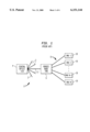
- a standard PON model is shown in FIG. 1, and consists of a first fiber star 1, typically a plurality of optical fibers 2 extending from a central office 4, to one of a plurality of remote nodes 6, i.e., RN 1 , RN 2 , . . . RN N . Downstream signals are transmitted from the CO 4 towards the remote node for further distribution.
- light is passively split and distributed via a plurality of optical fibers 8 (a second star) to a plurality of optical network units (ONUs) 10, i.e., ONU 1 , ONU 2 , . . . ONU N .
- the ONUs 10 provide service to one or more end users wherein each downstream optical signal is received and electronically distributed to end users.
- the ONUs 10 may transmit upstream signals which are combined at the remote node.
- Each remote node 6 (or passive star) passively combines transmissions from the ONUs 10 onto a single optical fiber 2 for distribution to the CO.
- Two passive optical network architectures are a telephony over passive optical network (TPON) and a wavelength division multiplexing passive optical network (WDM PON).
- TPON telephony over passive optical network
- WDM PON wavelength division multiplexing passive optical network
- a CO broadcasts a downstream optical signal to all ONUs using time division multiplexing (TDM) protocol.
- TDM time division multiplexing
- TDM typically includes a frame of information subdivided into time slots assigned to individual ONUs.
- Wavelength division multiplexing is a technology in which multiple wavelengths share the same optical fiber in order to increase the capacity and configurability of networks.
- WDM generally increases optical system capacity by simultaneously transmitting data on several optical carrier signals at different wavelengths. The total system capacity is increased by a factor equal to the number of different wavelength channels.
- WDM PONs utilize an architecture within which each ONU or subscriber is assigned a unique wavelength by the central office. Signals destined for each remote node (and ultimately, each optical network unit) are created by modulating light at N distinct wavelengths at the CO. The modulated light is multiplexed onto a fiber directed to the remote node. The downstream signals are split and distributed to the ONU as a function of wavelength within a wavelength division demultiplexer at the remote node. In the upstream transmission direction (optical network unit to remote node), the light is transmitted at assigned wavelengths, typically by a laser.
- WDM PONs Compared to TDM PONs, WDM PONs have the advantage that they do not broadcast individual subscribers' data to all premises. As a result, privacy is enhanced and the electronics in the ONU need only operate at the subscriber's data rate.
- upstream transmission through a wavelength routing device can be difficult. Temperature-controlled single-frequency lasers at each home are impractical. Spectral slicing of light emitting diodes and the use of modulators combined with an optical loopback have also been used. Another approach is to use low-cost, uncooled Fabry-Perot lasers at the home and combine them at the remote node with a passive splitter.
- wavelength division multiplexing with different services on different wavelengths, requires additional optical transmitters and receivers to be installed wherever an expansion of services and additional channels is required.
- Each remote unit is assigned a different frequency using a wavelength router.
- this WDM system is not commercially viable for mass market applications like fiber distribution to the home.
- One such problem is the small number of channels currently accommodated.
- Present multichannel laser diodes are very difficult to fabricate with acceptable yield even with as few as eight channels.
- passive WDM splitters currently available have a large temperature variation of their passband channels, thereby requiring a continuous tunability in the multichannel sources that has not yet been achieved.
- PON power splitting PON
- TDMA time division multiplexed access
- the passive optical network system and method for providing a predetermined wavelength of data to remote users includes a multiple wavelength transmitter for transmitting a multiwavelength signal.
- the multiwavelength signal includes a plurality of signal components of predetermined wavelengths provided by a plurality of access providers. Each access provider provides a signal component of wavelength different from that of the other access providers.
- a power-splitting passive optical network receives and power-splits the multiwavelength signal into a plurality of distributed multiwavelength signals each associated with a respective remote user.
- a filter selectively filters out, for each remote user, ones of the signal components of the associated distributed multiwavelength signal to provide the remote user with a selected one signal component of predetermined wavelength.
- FIG. 1 is a diagram of a conventional passive optical network model.
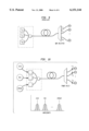
- FIG. 2 is a diagram of an exemplary network system in accordance with the present invention.
- FIG. 3 is a diagram of another exemplary network system in accordance with the present invention.
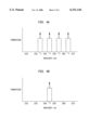
- FIG. 4A shows a chart showing transmission vs. wavelength for various access providers in an exemplary network system.
- FIG. 4B shows a chart showing transmission vs. wavelength of filtered data received at a remote unit.
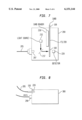
- FIG. 5 shows an exemplary access card in accordance with the present invention.
- FIG. 6 shows an exemplary optical network unit in accordance with the present invention.
- FIG. 7 shows further detail of the exemplary optical network unit shown in FIG. 6.
- FIG. 8 shows a further exemplary device in accordance with the present invention.
- FIG. 9 diagram of a conventional wavelength division multiplexed passive optical network.
- FIG. 10 shows an exemplary optical network unit in accordance with the present invention.
- the present invention is directed to upgrading an existing power-splitting passive optical network (PSPON) to act as an effective full wavelength division multiplexed (WDM) PON.
- PSPON power-splitting passive optical network
- WDM wavelength division multiplexed
- the present invention uses multiple access providers that each use a multiwavelength transmitter in a central office (CO) and each sends at least one wavelength to the PSPON.
- CO central office
- Each optical network unit (ONU) at a remote unit receives all the wavelengths.
- a filter is placed in each ONU so that each remote unit receives a particular, though not necessarily different, wavelength. This effectively acts as a WDM PON at a much lower cost than a true WDM PON.
- the ONUs are preferably identical.
- the present invention uses flexible TDM bandwidth allocation, as in a conventional PSPON system. Upstream is still shared unless otherwise provided. It appears to every access provider (such as AT&T, MCI, etc.) that they own the entire PON. If a new access provider accesses the PON, the total bandwidth that the other access providers can deliver is not reduced. Consumers are readily able to switch providers by using a filter to change the wavelength they receive.
- FIG. 2 shows an exemplary network system in which multiple access providers 20, 22 and 24 each have access to all the remote units 40, 42, 44 through respective power splitters 30, 32, 34.
- first provider 20 provides a signal at a particular bandwidth (or wavelength) to a power splitter 30.
- the power splitter 30 distributes the signal to every remote unit 40, 42, 44 in the system.
- Each remote unit 40, 42, 44 having the proper receiving equipment receives the signal.
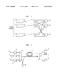
- FIG. 3 shows another exemplary network system in which multiple access providers 47, 48, 49 each have access to all the remote units 80, 82, 84 in a system.
- Each of the three shown access providers 47, 48, 49 transmits using a respective distributed feedback laser 50, 52, 54 which transmit at different wavelengths ⁇ 1 , ⁇ 2 , ⁇ N .
- the optical signals are passed through a multiple channel filter device such as a waveguide grating router or power splitter 60 and passed to the optical fibers 65 comprising a distribution system.
- the signals are received at a power splitter 70 (e.g., a 1 ⁇ M power splitter) and provided to the remote units 80, 82, 84 which have an appropriate filter to receive the desired signals and filter out the unwaited or unauthorized signals.
- An upstream shared time division multiplexer 90 is also shown and is used to transmit optically encoded signals upstream to the remote node to form a multiplexed signal for distribution to the CO.
- Each remote unit has equal access to all service providers using provider WDM (PWDM) and ONU filtering.
- Optical filtering at the ONU provides flexibility.
- the PSPON sends all the wavelengths to all the customers on a PON.
- Each access provider uses a different wavelength to transmit their data, as shown for four exemplary providers in FIG. 4A.
- Provider 1 transmits data at a first bandwidth of wavelength ⁇ 1
- provider 2 transmits data at a second bandwidth of wavelength ⁇ 2
- provider 3 transmits data at a third bandwidth of wavelength ⁇ 3
- provider 4 transmits data at a fourth bandwidth of wavelength ⁇ 4 .
- Each remote unit receives all the bandwidths and wavelengths, thus all the data, but each remote unit contains a filter so that only the desired wavelength or data is ultimately received by the user. For example, as shown in FIG. 4B, only the data from provider 2 having a bandwidth wavelength ⁇ 2 is received by the user after filtering. Thus, the data from each access provider is transmitted to each remote unit. At the remote unit, a filter is provided so that the user at the remote unit filters out the unwanted data and only gets the bandwidth it subscribes to. Thus, each access provider has access to the full downstream PON bandwidth (e.g., 622 Mb/s). The customer can change access provider by changing the optical filter provided on an access card.
- PON bandwidth e.g., 622 Mb/s
- each ONU receives all the wavelengths sent by all the access providers, and a filter is used at the remote unit to provide the wavelengths in the bandwidth that the user seeks access to.
- the filter is incorporated into a card that each user receives.
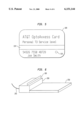
- An exemplary card 100 in accordance with the present invention is shown in FIG. 5.
- the card 100 incorporates an optical filter 110 and a magnetic stripe 120, barcode, or other means for user verification and identification. Accordingly, wavelength-encoding is possible.
- a card with an optical filter in it is provided to the remote end user (e.g., a consumer or access provider subscriber) who uses it to select the bandwidth wavelengths or channel that the remote unit is to receive.
- the filter 110 can be a transmissive or reflective holographic filter, a transmissive or reflective interference filter, or any type of transmissive or reflective thin-film optical filter.
- the user can change (e.g., upgrade) to different wavelengths by having a different filter put on the card; e.g., the user can upgrade from a low cost, low speed data channel to a more expensive, high speed data channel.
- the user selects the bandwidth to receive by inserting the card into an ONU at the remote unit.
- a thin-film narrowband optical filter is laminated into the card, and that portion of the card is positioned between a fiber exit and a receiver preferably using a graded index (GRIN) lens.
- GRIN graded index
- the magnetic stripe is read by the ONU and sends back a signal indicating that the authorized user is receiving the correct bandwidth signal.
- GRIN graded index
- the filter passband is preferably made highly temperature-independent, and designed for high transmittance.
- the power budget for the present invention is not much different than a conventional PSPON because current CPON routers specify a 10 dB on-channel loss, compared to a 12 dB loss for a 16-port power splitter. This also eliminates the wavelength routers completely from the CPON, along with a temperature tuning problem that causes many problems.
- the broad spectrum output from a suitable optical source (not shown)--illustratively, a light emitting diode (LED) having an output centered at a typical telecommunications wavelength such as, for example, 1.55 ⁇ m--provides the incoming data signal to an ONU 200 through a fiber 205.
- the ONU 200 has a card reader 210 in which the user inserts the card 100 containing the filter 110.
- the card reader 210 reads the magnetic stripe 120 or barcode for user identification and verification.
- the incoming optical signal passes through a GRIN lens 207 which acts as a receiver, passes through a dichroic mirror 217, and passes through the optical filter 110 on the card 100.
- a detector 220 detects the transmitted optical signal that passes through the filter 110 and provides it to the next part of the system, for example, a conventional person computer miniature card interface adapter 250 (PCMCIA).
- a multiwavelength transmitter is installed in the CO for each PON and emits signals on a predetermined number of different wavelengths (or wavelength channels) at a predetermined data rate, preferably 16 different wavelengths at a 52 or 155 Mb/s data rate per channel, for local access applications.
- Each customer on the PON receives a card that is to be inserted into the ONU.
- a small thin-film interference filter is laminated into each card and transmits one of the wavelength bands. When inserted, the filter is disposed between the fiber and the detector, preferably using one or a pair of GRIN lenses.
- the filter peak transmission is made high (preferably about 80%) and the blocking of adjacent channels is set greater than 20 dB, with a substantially flat top.
- the passband of the filter is rendered temperature insensitive using conventional methods such as those used in current WDM routers. Therefore, the temperature tuning problem of the WDM routers is not present in the exemplary embodiment; therefore, large wavelength spacings are not required for ⁇ set-and-forget ⁇ operation.
- Each ONU receives the full 52 or 155 Mb/s, and can be further upgraded to a high data rate system of 622 Mb/s, if desired.
- a 16-way power split causes a 12 dB loss
- conventional WDM routers cause a 10 dB loss, therefore as long, as the filter transmission is nearly 100% at peak, the loss budgets are comparable.
- receivers operate at 155 MHz or greater.
- the filters are placed inside the remote splitting node.
- the filters preferably transmit the 1.3 ⁇ m light also.
- Such two-band filters could be made with a slightly more complex layer design, however getting out of the fiber and back into the fiber is much more complex and expensive than just putting the interference filter in front of the photodetector in the ONU, especially if the remote splitter has to be a rugged unit that hangs on the side of a telephone pole.
- the entire ONU is put into a PCMCIA-type card 300, so that it incorporates all the features of the ONU, including the filter 110, and can be easily exchanged by the user.
- the PCMCIA card contains the optical filter 110 and the customer registration information. Because this is WDM, no time demultiplexing electronics is required, thereby simplifying and reducing power requirements. Also provided, though optional, is a POTS (plain old telephone service) input 290. It should also be noted that the upstream laser diode would have to be built into this unit, also.
Abstract
Description
Claims (17)
Priority Applications (1)
| Application Number | Priority Date | Filing Date | Title |
|---|---|---|---|
| US09/009,439 US6151144A (en) | 1998-01-20 | 1998-01-20 | Wavelength division multiplexing for unbundling downstream fiber-to-the-home |
Applications Claiming Priority (1)
| Application Number | Priority Date | Filing Date | Title |
|---|---|---|---|
| US09/009,439 US6151144A (en) | 1998-01-20 | 1998-01-20 | Wavelength division multiplexing for unbundling downstream fiber-to-the-home |
Publications (1)
| Publication Number | Publication Date |
|---|---|
| US6151144A true US6151144A (en) | 2000-11-21 |
Family
ID=21737654
Family Applications (1)
| Application Number | Title | Priority Date | Filing Date |
|---|---|---|---|
| US09/009,439 Expired - Lifetime US6151144A (en) | 1998-01-20 | 1998-01-20 | Wavelength division multiplexing for unbundling downstream fiber-to-the-home |
Country Status (1)
| Country | Link |
|---|---|
| US (1) | US6151144A (en) |
Cited By (35)
| Publication number | Priority date | Publication date | Assignee | Title |
|---|---|---|---|---|
| WO2002019571A1 (en) * | 2000-08-25 | 2002-03-07 | R & Dm Foundation | Shared multi-channel optical interface |
| US6452700B1 (en) | 2001-01-11 | 2002-09-17 | R&Dm Foundation | Computer backplane employing free space optical interconnect |
| US20020191254A1 (en) * | 2001-06-19 | 2002-12-19 | Robert Mays | Network routing employing free-space optical broadcasting |
| US20020191598A1 (en) * | 2001-06-19 | 2002-12-19 | Robert Mays | Network switch employing free-space optical switching technique |
| US20020196491A1 (en) * | 2001-06-25 | 2002-12-26 | Deng Kung Li | Passive optical network employing coarse wavelength division multiplexing and related methods |
| WO2003017531A1 (en) * | 2001-08-13 | 2003-02-27 | Corvis Corporation | Systems and methods for placing line terminating equipment of optical communications systems in customer points of presence |
| US6577422B1 (en) * | 1998-02-18 | 2003-06-10 | At&T Corp. | Long reach delivery of broadcast services using broadband optical sources and pre-compensation dispersion |
| US20040071466A1 (en) * | 2002-10-10 | 2004-04-15 | Buckman Lisa A. | Controlled optical splitter using a diffractive optical element and optical demultiplexer incorporating same |
| US20040175173A1 (en) * | 2003-03-07 | 2004-09-09 | Sbc, Inc. | Method and system for delivering broadband services over an ultrawide band radio system integrated with a passive optical network |
| US6832046B1 (en) * | 1999-05-11 | 2004-12-14 | Mahi Networks | Method and apparatus for multirate transmission in a passive optical network |
| US6853812B2 (en) | 2001-05-09 | 2005-02-08 | Robert Mays, Jr. | Polarized-holographic filtering providing improved extinction ratio |
| US6944404B2 (en) * | 2000-12-11 | 2005-09-13 | Harris Corporation | Network transceiver for extending the bandwidth of optical fiber-based network infrastructure |
| US20060152611A1 (en) * | 2002-11-15 | 2006-07-13 | Matsushita Electric Industrial Co., Ltd., | Image pickup device |
| US7082267B1 (en) | 2000-08-25 | 2006-07-25 | R& Dm Foundation | Shared multi-channel parallel optical interface |
| US20070140693A1 (en) * | 2005-12-13 | 2007-06-21 | Wen Li | Fiber-to-the-premise optical communication system |
| US20070154219A1 (en) * | 2001-05-08 | 2007-07-05 | Broadwing Corporation | Interconnections and protection between optical communications networks |
| US7263288B1 (en) * | 2001-12-03 | 2007-08-28 | Cheetah Omni, Llc | Optical routing using a star switching fabric |
| US20070264021A1 (en) * | 2006-04-28 | 2007-11-15 | Wen Li | High-speed fiber-to-the-premise optical communication system |
| US20070280690A1 (en) * | 2006-06-02 | 2007-12-06 | Fujitsu Limited | System and Method for Managing Power in an Optical Network |
| US20070280695A1 (en) * | 2006-06-02 | 2007-12-06 | Wen Li | Adaptive optical transceiver for fiber access communications |
| US20080089699A1 (en) * | 2006-10-17 | 2008-04-17 | Wen Li | Methods for automatic tuning optical communication system |
| US20080279567A1 (en) * | 2007-05-09 | 2008-11-13 | Wen Huang | Asymmetric ethernet optical network system |
| US20090003829A1 (en) * | 2007-06-29 | 2009-01-01 | Alcatel Lucent | Dwdm hybrid pon lt configuration |
| US20090116845A1 (en) * | 2007-11-02 | 2009-05-07 | Wen Li | Tetintelligent optical transceiver capable of optical-layer management |
| WO2009079167A1 (en) | 2007-12-14 | 2009-06-25 | Verizon Services Organization Inc. | High performance gigabit passive optical network |
| US20090214221A1 (en) * | 2008-02-21 | 2009-08-27 | Wen Li | Intelligent optical systems and methods for optical-layer management |
| US20090304384A1 (en) * | 2008-06-05 | 2009-12-10 | Wen Li | Intelligent pluggable transceiver stick capable of diagnostic monitoring and optical network management |
| US20090324237A1 (en) * | 2008-06-26 | 2009-12-31 | Fulin Pan | Pluggable optical network unit capable of status indication |
| EP2180622A1 (en) * | 2008-10-21 | 2010-04-28 | Nokia Siemens Networks OY | A passive optical network and a method for identification of a subscriber in a passive optical network |
| US20100215359A1 (en) * | 2009-02-22 | 2010-08-26 | Wen Li | Smart optical transceiver having integrated optical dying gasp function |
| US20100310252A1 (en) * | 2007-10-24 | 2010-12-09 | Peter Healey | Optical communication |
| US20120121220A1 (en) * | 2009-06-13 | 2012-05-17 | Technische Universitaet Dortmund | Method and device for transmission of optical data between transmitter station and receiver station via of a multi-mode light wave guide |
| US8953943B2 (en) | 2011-10-24 | 2015-02-10 | Google Technology Holdings LLC | Methods and systems for synchronous signaling across multiple downstream wavelengths in a passive optical network |
| US20170090139A1 (en) * | 2015-09-28 | 2017-03-30 | Commscope Technologies Llc | Fiber optic cable spool |
| US11063665B2 (en) | 2017-11-30 | 2021-07-13 | Purelifi Limited | Tuneable filter grating for OWC |
Citations (14)
| Publication number | Priority date | Publication date | Assignee | Title |
|---|---|---|---|---|
| US5341365A (en) * | 1989-11-24 | 1994-08-23 | British Telecommunications Public Limited Company | Passive optical network |
| US5426701A (en) * | 1994-02-28 | 1995-06-20 | General Instrument Corporation Of Delaware | Cable television converter box with a smart card connector underneath |
| US5453988A (en) * | 1990-01-24 | 1995-09-26 | British Telecommunications Public Limited Company | Passive optical network |
| US5479286A (en) * | 1993-08-04 | 1995-12-26 | British Telecommunications Public Limited Company | Optical fibre communications system |
| US5548432A (en) * | 1990-10-18 | 1996-08-20 | British Telecommunications Public Limited Company | Passive optical network switchable between an operational mode and a diagnostic mode |
| US5574584A (en) * | 1994-10-20 | 1996-11-12 | Lucent Technologies Inc. | Wavelength division multiplexing passive optical network with bi-directional optical spectral slicing |
| US5594578A (en) * | 1990-12-11 | 1997-01-14 | British Telecommunications Public Limited Company | Optical communications system including doped optical fiber filter |
| US5631758A (en) * | 1995-10-26 | 1997-05-20 | Lucent Technologies Inc. | Chirped-pulse multiple wavelength telecommunications system |
| US5768539A (en) * | 1994-05-27 | 1998-06-16 | Bell Atlantic Network Services, Inc. | Downloading applications software through a broadcast channel |
| US5799081A (en) * | 1995-09-18 | 1998-08-25 | Lg Electronics Inc. | Illegal view/copy protection method and apparatus for digital broadcasting system |
| US5808762A (en) * | 1994-11-25 | 1998-09-15 | Pirelli Cavi S.P.A. | Telecommunication system and method for wavelength-division multiplexing transmissions with a controlled separation of the outgoing channels and capable of determining the optical signal/noise ratio |
| US5878134A (en) * | 1994-10-03 | 1999-03-02 | News Data Com Ltd. | Secure access systems utilizing more than one IC card |
| US5880865A (en) * | 1996-12-03 | 1999-03-09 | Lucent Technologies Inc. | Wavelength-division-multiplexed network having broadcast capability |
| US5973475A (en) * | 1998-09-04 | 1999-10-26 | Ic-Tv Interactive Cyber Television Inc. | Remote smart battery |
-
1998
- 1998-01-20 US US09/009,439 patent/US6151144A/en not_active Expired - Lifetime
Patent Citations (14)
| Publication number | Priority date | Publication date | Assignee | Title |
|---|---|---|---|---|
| US5341365A (en) * | 1989-11-24 | 1994-08-23 | British Telecommunications Public Limited Company | Passive optical network |
| US5453988A (en) * | 1990-01-24 | 1995-09-26 | British Telecommunications Public Limited Company | Passive optical network |
| US5548432A (en) * | 1990-10-18 | 1996-08-20 | British Telecommunications Public Limited Company | Passive optical network switchable between an operational mode and a diagnostic mode |
| US5594578A (en) * | 1990-12-11 | 1997-01-14 | British Telecommunications Public Limited Company | Optical communications system including doped optical fiber filter |
| US5479286A (en) * | 1993-08-04 | 1995-12-26 | British Telecommunications Public Limited Company | Optical fibre communications system |
| US5426701A (en) * | 1994-02-28 | 1995-06-20 | General Instrument Corporation Of Delaware | Cable television converter box with a smart card connector underneath |
| US5768539A (en) * | 1994-05-27 | 1998-06-16 | Bell Atlantic Network Services, Inc. | Downloading applications software through a broadcast channel |
| US5878134A (en) * | 1994-10-03 | 1999-03-02 | News Data Com Ltd. | Secure access systems utilizing more than one IC card |
| US5574584A (en) * | 1994-10-20 | 1996-11-12 | Lucent Technologies Inc. | Wavelength division multiplexing passive optical network with bi-directional optical spectral slicing |
| US5808762A (en) * | 1994-11-25 | 1998-09-15 | Pirelli Cavi S.P.A. | Telecommunication system and method for wavelength-division multiplexing transmissions with a controlled separation of the outgoing channels and capable of determining the optical signal/noise ratio |
| US5799081A (en) * | 1995-09-18 | 1998-08-25 | Lg Electronics Inc. | Illegal view/copy protection method and apparatus for digital broadcasting system |
| US5631758A (en) * | 1995-10-26 | 1997-05-20 | Lucent Technologies Inc. | Chirped-pulse multiple wavelength telecommunications system |
| US5880865A (en) * | 1996-12-03 | 1999-03-09 | Lucent Technologies Inc. | Wavelength-division-multiplexed network having broadcast capability |
| US5973475A (en) * | 1998-09-04 | 1999-10-26 | Ic-Tv Interactive Cyber Television Inc. | Remote smart battery |
Non-Patent Citations (6)
| Title |
|---|
| "Dense WDM Multiplexing", Piriodical, Photonic Integration Research, Inc., No. 12, Feb., 1997. |
| C. R. Giles et al., "Access PON Using Downstream 1550-nm WDM Routing and Upstream 1300-nm Combining Through a Fiber-Grating Router", IEEE Photonics Technology Letters vol. 8, No. 11, (1996). |
| C. R. Giles et al., Access PON Using Downstream 1550 nm WDM Routing and Upstream 1300 nm Combining Through a Fiber Grating Router , IEEE Photonics Technology Letters vol. 8, No. 11, (1996). * |
| Dense WDM Multiplexing , Piriodical, Photonic Integration Research, Inc., No. 12, Feb., 1997. * |
| Lucent Technologies, "Dense Wavelength Division Multiplexers", 1997. |
| Lucent Technologies, Dense Wavelength Division Multiplexers , 1997. * |
Cited By (60)
| Publication number | Priority date | Publication date | Assignee | Title |
|---|---|---|---|---|
| US6577422B1 (en) * | 1998-02-18 | 2003-06-10 | At&T Corp. | Long reach delivery of broadcast services using broadband optical sources and pre-compensation dispersion |
| US6832046B1 (en) * | 1999-05-11 | 2004-12-14 | Mahi Networks | Method and apparatus for multirate transmission in a passive optical network |
| WO2002019571A1 (en) * | 2000-08-25 | 2002-03-07 | R & Dm Foundation | Shared multi-channel optical interface |
| US7099590B2 (en) | 2000-08-25 | 2006-08-29 | R&Dm Foundation | Filtering technique for free space interconnects |
| US7082267B1 (en) | 2000-08-25 | 2006-07-25 | R& Dm Foundation | Shared multi-channel parallel optical interface |
| US20050226618A1 (en) * | 2000-12-11 | 2005-10-13 | Harris Corporation | Network transceiver for extending the bandwidth of optical fiber-based network infrastructure |
| US7164863B2 (en) | 2000-12-11 | 2007-01-16 | Harris Corporation | Network transceiver for extending the bandwidth of optical fiber-based network infrastructure |
| US6944404B2 (en) * | 2000-12-11 | 2005-09-13 | Harris Corporation | Network transceiver for extending the bandwidth of optical fiber-based network infrastructure |
| US6452700B1 (en) | 2001-01-11 | 2002-09-17 | R&Dm Foundation | Computer backplane employing free space optical interconnect |
| US7415211B2 (en) | 2001-05-08 | 2008-08-19 | Dorsal Networks L.L.C. | Interconnections and protection between optical communications networks |
| US20070154219A1 (en) * | 2001-05-08 | 2007-07-05 | Broadwing Corporation | Interconnections and protection between optical communications networks |
| US6853812B2 (en) | 2001-05-09 | 2005-02-08 | Robert Mays, Jr. | Polarized-holographic filtering providing improved extinction ratio |
| US20020191598A1 (en) * | 2001-06-19 | 2002-12-19 | Robert Mays | Network switch employing free-space optical switching technique |
| US20020191254A1 (en) * | 2001-06-19 | 2002-12-19 | Robert Mays | Network routing employing free-space optical broadcasting |
| US20020196491A1 (en) * | 2001-06-25 | 2002-12-26 | Deng Kung Li | Passive optical network employing coarse wavelength division multiplexing and related methods |
| WO2003017531A1 (en) * | 2001-08-13 | 2003-02-27 | Corvis Corporation | Systems and methods for placing line terminating equipment of optical communications systems in customer points of presence |
| US7113706B2 (en) | 2001-08-13 | 2006-09-26 | Lee Feinberg | Systems and methods for placing line terminating equipment of optical communication systems in customer points of presence |
| US7424224B2 (en) | 2001-08-13 | 2008-09-09 | Dorsal Networks, Llc | Systems and methods for placing line terminating equipment of optical communication systems in customer points of presence |
| US7263288B1 (en) * | 2001-12-03 | 2007-08-28 | Cheetah Omni, Llc | Optical routing using a star switching fabric |
| US20040071466A1 (en) * | 2002-10-10 | 2004-04-15 | Buckman Lisa A. | Controlled optical splitter using a diffractive optical element and optical demultiplexer incorporating same |
| US20060152611A1 (en) * | 2002-11-15 | 2006-07-13 | Matsushita Electric Industrial Co., Ltd., | Image pickup device |
| US20040175173A1 (en) * | 2003-03-07 | 2004-09-09 | Sbc, Inc. | Method and system for delivering broadband services over an ultrawide band radio system integrated with a passive optical network |
| US7962042B2 (en) | 2003-03-07 | 2011-06-14 | At&T Intellectual Property I, L.P. | Method and system for delivering broadband services over an ultrawide band radio system integrated with a passive optical network |
| US20070140693A1 (en) * | 2005-12-13 | 2007-06-21 | Wen Li | Fiber-to-the-premise optical communication system |
| US7440701B2 (en) | 2005-12-13 | 2008-10-21 | Broadway Networks, Ltd. | Fiber-to-the-premise optical communication system |
| US7450848B2 (en) | 2006-04-28 | 2008-11-11 | Broadway Networks, Ltd, | High-speed fiber-to-the-premise optical communication system |
| US20070264020A1 (en) * | 2006-04-28 | 2007-11-15 | Wen Li | High-speed fiber-to-the-premise optical communication system |
| US7493042B2 (en) | 2006-04-28 | 2009-02-17 | Broadway Networks, Ltd. | High-speed fiber-to-the-premise optical communication system |
| US20070264021A1 (en) * | 2006-04-28 | 2007-11-15 | Wen Li | High-speed fiber-to-the-premise optical communication system |
| US7317874B2 (en) | 2006-06-02 | 2008-01-08 | Broadway Networks, Inc. | Adaptive optical transceiver for fiber access communications |
| US20070280695A1 (en) * | 2006-06-02 | 2007-12-06 | Wen Li | Adaptive optical transceiver for fiber access communications |
| US20070280690A1 (en) * | 2006-06-02 | 2007-12-06 | Fujitsu Limited | System and Method for Managing Power in an Optical Network |
| US20080089699A1 (en) * | 2006-10-17 | 2008-04-17 | Wen Li | Methods for automatic tuning optical communication system |
| US20080279567A1 (en) * | 2007-05-09 | 2008-11-13 | Wen Huang | Asymmetric ethernet optical network system |
| US20090003829A1 (en) * | 2007-06-29 | 2009-01-01 | Alcatel Lucent | Dwdm hybrid pon lt configuration |
| US9300425B2 (en) * | 2007-06-29 | 2016-03-29 | Alcatel Lucent | DWDM hybrid PON LT configuration |
| US20100310252A1 (en) * | 2007-10-24 | 2010-12-09 | Peter Healey | Optical communication |
| US8818201B2 (en) * | 2007-10-24 | 2014-08-26 | British Telecommunications Plc | Optical communication |
| US20090116845A1 (en) * | 2007-11-02 | 2009-05-07 | Wen Li | Tetintelligent optical transceiver capable of optical-layer management |
| EP2245766A4 (en) * | 2007-12-14 | 2012-05-30 | Verizon Patent & Licensing Inc | High performance gigabit passive optical network |
| WO2009079167A1 (en) | 2007-12-14 | 2009-06-25 | Verizon Services Organization Inc. | High performance gigabit passive optical network |
| EP2245766A1 (en) * | 2007-12-14 | 2010-11-03 | Verizon Patent and Licensing Inc. | High performance gigabit passive optical network |
| US8380087B2 (en) | 2007-12-14 | 2013-02-19 | Verizon Patent And Licensing Inc. | High performance gigabit passive optical network |
| US20110217042A1 (en) * | 2007-12-14 | 2011-09-08 | Verizon Patent And Licensing, Inc. | High performance gigabit passive optical network |
| US20090214221A1 (en) * | 2008-02-21 | 2009-08-27 | Wen Li | Intelligent optical systems and methods for optical-layer management |
| US7933518B2 (en) | 2008-02-21 | 2011-04-26 | Finisar Corporation | Intelligent optical systems and methods for optical-layer management |
| US20090304384A1 (en) * | 2008-06-05 | 2009-12-10 | Wen Li | Intelligent pluggable transceiver stick capable of diagnostic monitoring and optical network management |
| US7974537B2 (en) | 2008-06-05 | 2011-07-05 | Finisar Corporation | Intelligent pluggable transceiver stick capable of diagnostic monitoring and optical network management |
| US7957650B2 (en) | 2008-06-26 | 2011-06-07 | Finisar Corporation | Pluggable optical network unit capable of status indication |
| US20090324237A1 (en) * | 2008-06-26 | 2009-12-31 | Fulin Pan | Pluggable optical network unit capable of status indication |
| EP2180622A1 (en) * | 2008-10-21 | 2010-04-28 | Nokia Siemens Networks OY | A passive optical network and a method for identification of a subscriber in a passive optical network |
| US9246590B2 (en) | 2009-02-22 | 2016-01-26 | Finisar Corporation | Smart optical transceiver having integrated optical dying gasp function |
| US20100215359A1 (en) * | 2009-02-22 | 2010-08-26 | Wen Li | Smart optical transceiver having integrated optical dying gasp function |
| US20120121220A1 (en) * | 2009-06-13 | 2012-05-17 | Technische Universitaet Dortmund | Method and device for transmission of optical data between transmitter station and receiver station via of a multi-mode light wave guide |
| US8582932B2 (en) * | 2009-06-13 | 2013-11-12 | Technische Universitaet Dortmund | Method and device for transmission of optical data between transmitter station and receiver station via of a multi-mode light wave guide |
| US8953943B2 (en) | 2011-10-24 | 2015-02-10 | Google Technology Holdings LLC | Methods and systems for synchronous signaling across multiple downstream wavelengths in a passive optical network |
| US20170090139A1 (en) * | 2015-09-28 | 2017-03-30 | Commscope Technologies Llc | Fiber optic cable spool |
| US10495835B2 (en) * | 2015-09-28 | 2019-12-03 | Commscope Technologies Llc | Fiber optic cable spool |
| US10838163B2 (en) * | 2015-09-28 | 2020-11-17 | Commscope Technologies Llc | Fiber optic cable spool |
| US11063665B2 (en) | 2017-11-30 | 2021-07-13 | Purelifi Limited | Tuneable filter grating for OWC |
Similar Documents
| Publication | Publication Date | Title |
|---|---|---|
| US6151144A (en) | Wavelength division multiplexing for unbundling downstream fiber-to-the-home | |
| US6144472A (en) | Upgrading a power-splitting passive optical network using optical filtering | |
| CA2160823C (en) | A wavelength division multiplexing passive optical network with bi-dir ectional optical spectral slicing | |
| US7254330B2 (en) | Single fiber passive optical network wavelength division multiplex overlay | |
| Frigo et al. | A wavelength-division multiplexed passive optical network with cost-shared components | |
| US5864413A (en) | Passive optical network for dense WDM downstream data transmission and upstream data transmission | |
| US8554078B2 (en) | Passive optical network with plural optical line terminals | |
| US5311344A (en) | Bidirectional lightwave transmission system | |
| CA2209407C (en) | Optical communications system employing spectrally sliced optical source | |
| WO2010123285A4 (en) | Wdm pon system with distribution through a periodic arrayed waveguide grating | |
| US20020196491A1 (en) | Passive optical network employing coarse wavelength division multiplexing and related methods | |
| US20060239609A1 (en) | Methods and apparatuses to increase wavelength channels in a wavelength-division-multiplexing passive-optical-network | |
| KR100842290B1 (en) | Wavelength conversion apparatus in TDM-PON system based on WDM system and optical transmission apparatus and method using the same | |
| US6072612A (en) | WDM transmitter for optical networks using a loop-back spectrally sliced light emitting device | |
| Iannone et al. | High-speed point-to-point and multiple broadcast services delivered over a WDM passive optical network | |
| US6243175B1 (en) | WDM optical communication system having reduced loss and cross-talk | |
| US8139939B2 (en) | Upgradeable passive optical network | |
| US7486890B2 (en) | Optical transmission apparatus and method | |
| Giles et al. | Access PON using downstream 1550-nm WDM routing and upstream 1300-nm SCMA combining through a fiber-grating router | |
| Frigo et al. | A WDM PON architecture delivering point-to-point and multiple broadcast services using periodic properties of a WDM router | |
| US20040218924A1 (en) | Optical communications system and method for transmittin point-to-point and broadcast signals | |
| KR100596408B1 (en) | Apparatus for broadcasting service through overlay structure in WDM-PON | |
| Reichmann et al. | Simultaneous delivery of four independent broadcast television services over a wavelength-division multiplexed passive optical network | |
| Khan et al. | Design, implementation, and demonstration of a scalable three-stage, linear add-drop wavelength-division multiplexing passive optical network experimental test bed | |
| Jhunjhunwala et al. | Fibre Optic Local Loop |
Legal Events
| Date | Code | Title | Description |
|---|---|---|---|
| AS | Assignment |
Owner name: LUCENT TECHNOLOGIES, INC., NEW JERSEY Free format text: ASSIGNMENT OF ASSIGNORS INTEREST;ASSIGNOR:KNOX, WAYNE H.;REEL/FRAME:008939/0887 Effective date: 19980115 |
|
| STCF | Information on status: patent grant |
Free format text: PATENTED CASE |
|
| FEPP | Fee payment procedure |
Free format text: PAYOR NUMBER ASSIGNED (ORIGINAL EVENT CODE: ASPN); ENTITY STATUS OF PATENT OWNER: LARGE ENTITY |
|
| AS | Assignment |
Owner name: THE CHASE MANHATTAN BANK, AS COLLATERAL AGENT, TEX Free format text: CONDITIONAL ASSIGNMENT OF AND SECURITY INTEREST IN PATENT RIGHTS;ASSIGNOR:LUCENT TECHNOLOGIES INC. (DE CORPORATION);REEL/FRAME:011722/0048 Effective date: 20010222 |
|
| FEPP | Fee payment procedure |
Free format text: PAYER NUMBER DE-ASSIGNED (ORIGINAL EVENT CODE: RMPN); ENTITY STATUS OF PATENT OWNER: LARGE ENTITY Free format text: PAYOR NUMBER ASSIGNED (ORIGINAL EVENT CODE: ASPN); ENTITY STATUS OF PATENT OWNER: LARGE ENTITY |
|
| FPAY | Fee payment |
Year of fee payment: 4 |
|
| AS | Assignment |
Owner name: LUCENT TECHNOLOGIES INC., NEW JERSEY Free format text: TERMINATION AND RELEASE OF SECURITY INTEREST IN PATENT RIGHTS;ASSIGNOR:JPMORGAN CHASE BANK, N.A. (FORMERLY KNOWN AS THE CHASE MANHATTAN BANK), AS ADMINISTRATIVE AGENT;REEL/FRAME:018590/0287 Effective date: 20061130 |
|
| FPAY | Fee payment |
Year of fee payment: 8 |
|
| FPAY | Fee payment |
Year of fee payment: 12 |