US6152383A - Ultrasonic nebulizer - Google Patents
Ultrasonic nebulizer Download PDFInfo
- Publication number
- US6152383A US6152383A US09/444,510 US44451099A US6152383A US 6152383 A US6152383 A US 6152383A US 44451099 A US44451099 A US 44451099A US 6152383 A US6152383 A US 6152383A
- Authority
- US
- United States
- Prior art keywords
- container
- ultrasonic vibrator
- transmission medium
- sound
- tubular
- Prior art date
- Legal status (The legal status is an assumption and is not a legal conclusion. Google has not performed a legal analysis and makes no representation as to the accuracy of the status listed.)
- Expired - Fee Related
Links
Images


Classifications
-
- B—PERFORMING OPERATIONS; TRANSPORTING
- B05—SPRAYING OR ATOMISING IN GENERAL; APPLYING FLUENT MATERIALS TO SURFACES, IN GENERAL
- B05B—SPRAYING APPARATUS; ATOMISING APPARATUS; NOZZLES
- B05B17/00—Apparatus for spraying or atomising liquids or other fluent materials, not covered by the preceding groups
- B05B17/04—Apparatus for spraying or atomising liquids or other fluent materials, not covered by the preceding groups operating with special methods
- B05B17/06—Apparatus for spraying or atomising liquids or other fluent materials, not covered by the preceding groups operating with special methods using ultrasonic or other kinds of vibrations
- B05B17/0607—Apparatus for spraying or atomising liquids or other fluent materials, not covered by the preceding groups operating with special methods using ultrasonic or other kinds of vibrations generated by electrical means, e.g. piezoelectric transducers
- B05B17/0615—Apparatus for spraying or atomising liquids or other fluent materials, not covered by the preceding groups operating with special methods using ultrasonic or other kinds of vibrations generated by electrical means, e.g. piezoelectric transducers spray being produced at the free surface of the liquid or other fluent material in a container and subjected to the vibrations
Definitions
- the present invention relates to an ultrasonic nebulizer, and more particularly to such an ultrasonic nebulizer, which is practical for use in an inhaler, a humidifier, as well as a mist maker.
- a regular ultrasonic nebulizer for use in an inhaler, humidifier or mist maker is generally comprised of an ultrasonic vibrator controlled to produce sound field for making water or medicine into a mist.
- the sound field includes a far field area and a near field area.
- the border area between the far field area and the near field area is the sound wave energy concentrated area.
- U.S. Pat. No. 3,901,443 teaches a method of changing the sound wave emitting angle of an ultrasonic vibrator. According to U.S. Pat. No. 3,901,443, the sound wave emitting angle is set between 2°-22°.
- this method has its application limitation. For example, this method cannot eliminate refraction of sound waves in space, medicine cup, or partition means.
- the ultrasonic nebulizer comprises a container holding a transmission medium, an ultrasonic vibrator having a sound wave generating area controlled by an electronic drive circuit to produce sound waves, and a tubular wave guide connected between the container and the ultrasonic vibrator to concentrate sound waves from the ultrasonic vibrator onto the transmission medium in the container.
- the tubular wave-guide is formed integral with the container.
- through holes are provided for enabling the transmission medium to be circulated between the inner diameter of the tubular wave-guide and the holding chamber in the container.
- the tubular wave-guide has a smooth inside wall for guiding the sound waves effectively.
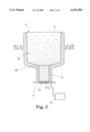
- FIG. 1 is a sectional view showing the arrangement of the tubular wave-guide, the container, and the electronic drive circuit for an ultrasonic nebulizer according to the present invention.
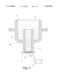
- FIG. 2 is a sectional view showing an alternate form of the ultrasonic nebulizer according to the present invention.
- FIG. 3 is a sectional view showing another alternate form of the ultrasonic nebulizer according to the present invention
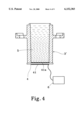
- FIG. 4 is a sectional view showing still another alternate form of the ultrasonic nebulizer according to the present invention.
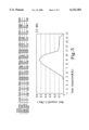
- FIG. 5 is a tube diameter-mist output chart obtained from an ultrasonic nebulizer under frequency 2.5 MHz according to the present invention.
- FIG. 6 is a tube diameter-mist output chart obtained from an ultrasonic nebulizer under frequency 1.63 MHz according to the present invention.
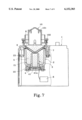
- FIG. 7 is a side view in section showing the ultrasonic nebulizer installed in an inhaler according to the present invention.
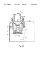
- FIG. 8 is similar to FIG. 7 but showing the transmission medium circulated through the holes between the tubular wave-guide and the holding chamber of the container.
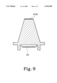
- FIG. 9 is a sectional view showing an alternate form of the ultrasonic vibrator according to the present invention.
- the present invention comprises a housing 1, a container 2 mounted inside the housing 1, a tubular wave guide 3 disposed in the container 2, a transmission medium (water or any liquid) 5 carried in the holding chamber 21 defined within the container 2, an ultrasonic vibrator 4 disposed at the bottom side of the tubular wave guide 3, and an electronic drive circuit 6 connected to the ultrasonic vibrator 4 to control its operation.
- the tubular wave-guide 3 can be formed integral with the container 2, or separately made and then fixedly fastened to the container 2.
- the ultrasonic vibrator 4 comprises a sound wave generating area 41a facing the inner diameter of the tubular wave-guide 3 (the sound wave generating area 41a is equal to the polarized area 41, which is the silver layer area on the ultrasonic vibrator 4 that produces vibration when receiving an AC voltage).
- the electronic drive circuit 6 is started to drive the ultrasonic vibrator 4
- the sound wave generating area 41a is driven to produce a sound field.
- the sound waves from the sound field are guided to the transmission medium 5 by the tubular wave guide 3, causing sound waves to rush out through the surface tension of the transmission medium (water or any liquid) 5 in the holding chamber 21 of the container 2.
- through holes 22 are disposed in communication between the tubular wave-guide 3 and the holding chamber 21 for circulation of the transmission medium 5 to improve nebulization efficiency.
- FIGS. 2 and 3 show different alternate forms of the present invention.
- the tubular wave-guide 3 protrudes over the bottom side of the container 2, and the ultrasonic vibrator 4 is mounted on the bottom end of the tubular wave-guide 3 with the sound wave generating area 41a disposed in contact with the transmission medium 5.
- the sound wave generating area 41a is driven to produce a sound field, enabling sound waves to be guided by the tubular wave guide 3 to rush out through the surface tension of the transmission medium (water or any liquid) 5 in the holding chamber 21 of the container 2, and therefore transmission medium 5 is nebulized.
- FIG. 4 shows still another alternate form of the present invention.
- the tubular wave guide 3' is formed integral with the container, and the ultrasonic vibrator 4 is mounted on the bottom end of the tubular wave guide 3' with the sound wave generating area 41a disposed in contact with the transmission medium 5.
- the sound wave generating area 41a is driven to produce a sound field, enabling sound waves to be guided by the tubular wave guide 3 to rush out through the surface tension of the transmission medium (water or any liquid) 5 in the holding chamber 21 of the container 2, and therefore transmission medium 5 is nebulized.
- the present invention uses a tubular wave guide 3 to concentrate and guide sound waves from an ultrasonic vibrator 4 to a transmission medium (water or any liquid) 5, causing the transmission medium to be nebulized into a mist.
- the inner diameter of the aforesaid tubular wave guide 3 is preferably about the diameter of the sound wave generating area 41a of the ultrasonic vibrator 4 ⁇ 30%, i.e., the inner diameter of the tubular wave guide 3 is determined subject to the sound wave generating area 41a.
- the relation between the inner diameter of the tubular wave guide and the ultrasonic vibrator is obtained from the test results shown in FIGS. 5 and 6 under the application of the apparatus shown in FIGS. 7 and 8. Test Apparatus for the test result shown in FIG. 5:
- Diameter of sound wave generating area 9 mm.
- Length 20-22 mm.
- Diameter of sound wave generating area 11 mm.
- Length 20-22 mm.
- the optimum nebulization effect is obtained under the condition that the inner diameter of the aforesaid tubular wave-guide 3 is about the diameter of the sound wave generating area 41a of the ultrasonic vibrator 4 ⁇ 30%.
- the nebulization effect becomes worse when the inner diameter of the tubular wave guide 3 is beyond the range of the diameter of the sound wave generating area 41a of the ultrasonic vibrator 4 ⁇ 30%, i.e., the wave concentrating and guiding performance of the tubular wave guide 3 drops when its inner diameter is beyond the e range of the diameter of the sound wave generating area 41a of the ultrasonic vibrator 4 ⁇ 30%.
- the inside wall of the tubular wave-guide 3 In order to transmit sound waves effectively, the inside wall of the tubular wave-guide 3 must be made smooth.
- the mounting portion 23 of the container 2 is fastened to the inside wall of the housing 1, and a partition member 7 is disposed in the container 2 at the top side.
- the partition member 7 can have a V-shaped or U-shaped cross section.
- the sound wave generating area 41a is driven to produce a sound field, enabling sound waves to be guided by the tubular wave-guide 3 to rush out through the surface tension of the liquid above the partition member 7, and therefore the liquid above the partition member 7 is nebulized.
- the partition member 7 can be fixedly fastened to the container 2.
- the partition member 7 can be a movable member attached to the container 2 at the topside.
- a measuring instrument 8 is mounted on the topside of the partition member 7 to indicate the amount of medicine employed.
- Another transmission medium 9 is provided between the partition member 7 and the measuring instrument 8.
- the sound wave generating area 41a is driven to produce a sound field, enabling sound waves to be guided by the tubular wave guide 3 to rush out through the surface tension of the medicine in the measuring instrument via the transmission medium 5 in the holding chamber 21 of the container 2 and the transmission medium 9 between the partition member 7 and the measuring instrument 8, and therefore the medicine is nebulized.
- a hood 10 is covered on the measuring instrument 8, defining with the measuring instrument 8 a nebulization chamber.
- a gasket 102 is provided at the bottom side of the hood 10 to seal the gap between the hood 10 and the container 2.
- FIG. 8 shows the circulation of the transmission medium 5.
- the transmission medium is forced to circulate through the through holes 22 between the tubular wave guide 3 and the holding chamber 21.
- FIG. 9 shows an alternate form of the ultrasonic vibrator according to the present invention.
- the sound wave generating area 41b is fixedly mounted on a horn.
Abstract
Description
Claims (3)
Priority Applications (1)
| Application Number | Priority Date | Filing Date | Title |
|---|---|---|---|
| US09/444,510 US6152383A (en) | 1999-11-22 | 1999-11-22 | Ultrasonic nebulizer |
Applications Claiming Priority (1)
| Application Number | Priority Date | Filing Date | Title |
|---|---|---|---|
| US09/444,510 US6152383A (en) | 1999-11-22 | 1999-11-22 | Ultrasonic nebulizer |
Publications (1)
| Publication Number | Publication Date |
|---|---|
| US6152383A true US6152383A (en) | 2000-11-28 |
Family
ID=23765217
Family Applications (1)
| Application Number | Title | Priority Date | Filing Date |
|---|---|---|---|
| US09/444,510 Expired - Fee Related US6152383A (en) | 1999-11-22 | 1999-11-22 | Ultrasonic nebulizer |
Country Status (1)
| Country | Link |
|---|---|
| US (1) | US6152383A (en) |
Cited By (45)
| Publication number | Priority date | Publication date | Assignee | Title |
|---|---|---|---|---|
| US6283118B1 (en) * | 1999-10-13 | 2001-09-04 | Hsueh-Yu Lu | Ultrasonic nebulizer |
| US6402046B1 (en) * | 1999-12-23 | 2002-06-11 | Drager Medizintechnik Gmbh | Ultrasonic atomizer |
| US20020104895A1 (en) * | 2001-02-07 | 2002-08-08 | Firmin Garcia | Fluid product dispenser |
| US6446878B1 (en) * | 1999-03-01 | 2002-09-10 | Sanjeev Chandra | Apparatus and method for generating droplets |
| US6578659B2 (en) * | 2000-12-01 | 2003-06-17 | Misonix Incorporated | Ultrasonic horn assembly |
| WO2004017848A1 (en) * | 2002-08-23 | 2004-03-04 | Sheiman Ultrasonic Research Foundation Pty Ltd | Nebulizing and drug delivery device |
| US20040079580A1 (en) * | 2002-10-28 | 2004-04-29 | Manna Ronald R. | Ultrasonic horn |
| US20040124258A1 (en) * | 2002-12-18 | 2004-07-01 | Monitto Perry H. | Misting fogger |
| US20060073173A1 (en) * | 2004-10-04 | 2006-04-06 | Maria Banach | Large-scale manufacturing process for the production of pharmaceutical compositions |
| US20060201500A1 (en) * | 2005-03-09 | 2006-09-14 | Ric Investments, Llc. | Nebulizing drug delivery device for ventilator |
| US20060201501A1 (en) * | 2005-03-09 | 2006-09-14 | Ric Investments, Llc | Nebulizing drug delivery device with interlock detection and temperature protection |
| US20060201502A1 (en) * | 2005-03-09 | 2006-09-14 | Ric Investments, Llc. | Nebulizing drug delivery device with increased flow rate |
| AU2003254386B2 (en) * | 2002-08-23 | 2006-10-12 | Sheiman Ultrasonic Research Foundation Pty Ltd | Nebulizing and drug delivery device |
| US20060241470A1 (en) * | 2005-03-23 | 2006-10-26 | Misonix Incorporated | Ultrasonic wound debrider probe and method of use |
| US20060243274A1 (en) * | 2005-03-09 | 2006-11-02 | Ric Investments, Llc | Nebulizing drug delivery device with barrier |
| US20070007673A1 (en) * | 2005-07-06 | 2007-01-11 | Wooritec Co. Ltd | Nebulizer for ultrasonic humidifier |
| WO2007028203A1 (en) * | 2005-09-06 | 2007-03-15 | Intelligent Medical Technologies Pty Limited | Nebuliser |
| US20070221212A1 (en) * | 2006-03-21 | 2007-09-27 | Yi-Hsin Huang | Liquid nebulizer |
| US20070295328A1 (en) * | 2006-06-21 | 2007-12-27 | Puthalath Koroth Raghuprasad | Cloud Nebulizer |
| US20080058775A1 (en) * | 2006-08-29 | 2008-03-06 | Darian Alexander L | Ultrasonic debrider probe and method of use |
| US20080110452A1 (en) * | 2006-11-15 | 2008-05-15 | Delphi Technologies Inc. | Nebulizer and method for controlling an amount of liquid that is atomized by the nebulizer |
| US20080110453A1 (en) * | 2006-11-15 | 2008-05-15 | Delphi Technologies Inc. | Nebulizer and methods for controlling the nebulizer |
| US20080156320A1 (en) * | 2007-01-03 | 2008-07-03 | Thomas Low | Ultrasonic nebulizer and method for atomizing liquid |
| US20100051717A1 (en) * | 2008-08-27 | 2010-03-04 | Hon Hai Precision Industry Co., Ltd. | Ultrasonic atomizer |
| US20100313883A1 (en) * | 2006-04-20 | 2010-12-16 | Koninklijke Philips Electronics N.V. | Ultrasonic bebulilzer with metal coated ultrasonic genrator |
| US7883031B2 (en) | 2003-05-20 | 2011-02-08 | James F. Collins, Jr. | Ophthalmic drug delivery system |
| US8012136B2 (en) | 2003-05-20 | 2011-09-06 | Optimyst Systems, Inc. | Ophthalmic fluid delivery device and method of operation |
| US20120114809A1 (en) * | 2008-12-03 | 2012-05-10 | Edwards David A | Delivering aerosolizable food products |
| US8353287B1 (en) * | 2006-04-20 | 2013-01-15 | Ric Investments, Llc | Disposable drug solution cup for an ultrasonic nebulizer |
| US8684980B2 (en) | 2010-07-15 | 2014-04-01 | Corinthian Ophthalmic, Inc. | Drop generating device |
| US8733935B2 (en) | 2010-07-15 | 2014-05-27 | Corinthian Ophthalmic, Inc. | Method and system for performing remote treatment and monitoring |
| US9087145B2 (en) | 2010-07-15 | 2015-07-21 | Eyenovia, Inc. | Ophthalmic drug delivery |
| US9339836B2 (en) | 2005-05-23 | 2016-05-17 | Biosonic Australia Pty Ltd | Ultrasonic atomization apparatus |
| US9440240B2 (en) | 2014-03-21 | 2016-09-13 | Brookstone Purchasing, Inc. | Combined ionic air filter and humidifier apparatus |
| US9573154B2 (en) | 2011-10-24 | 2017-02-21 | Aerodesigns, Inc. | Dispensing aerosols |
| US20170368271A1 (en) * | 2015-03-25 | 2017-12-28 | Omron Healthcare Co., Ltd. | Ultrasonic nebulizer |
| US20170368270A1 (en) * | 2015-03-25 | 2017-12-28 | Omron Healthcare Co., Ltd. | Ultrasonic nebulizer |
| CN108561998A (en) * | 2018-05-15 | 2018-09-21 | 汪智静 | A kind of ultrasonic humidifier with central mist pipe |
| US20180326445A1 (en) * | 2017-05-11 | 2018-11-15 | Zhijing Wang | Ultrasonic humidifier with a central atomizing tube |
| US10154923B2 (en) | 2010-07-15 | 2018-12-18 | Eyenovia, Inc. | Drop generating device |
| US10639194B2 (en) | 2011-12-12 | 2020-05-05 | Eyenovia, Inc. | High modulus polymeric ejector mechanism, ejector device, and methods of use |
| GB2602547A (en) * | 2020-08-24 | 2022-07-06 | Bloomy Lotus Ltd | Focused ultrasonic atomizer |
| EP3970525A4 (en) * | 2020-07-24 | 2022-07-27 | KT & G Corporation | Ultrasound-based aerosol-generating apparatus |
| US11846919B2 (en) | 2013-03-15 | 2023-12-19 | Vapor Communications, Inc. | Systems, methods and articles to provide olfactory sensations |
| US11938056B2 (en) | 2017-06-10 | 2024-03-26 | Eyenovia, Inc. | Methods and devices for handling a fluid and delivering the fluid to the eye |
Citations (6)
| Publication number | Priority date | Publication date | Assignee | Title |
|---|---|---|---|---|
| US3901443A (en) * | 1973-02-06 | 1975-08-26 | Tdk Electronics Co Ltd | Ultrasonic wave nebulizer |
| US4113809A (en) * | 1977-04-04 | 1978-09-12 | Champion Spark Plug Company | Hand held ultrasonic nebulizer |
| US4976259A (en) * | 1986-12-22 | 1990-12-11 | Mountain Medical Equipment, Inc. | Ultrasonic nebulizer |
| US5163617A (en) * | 1990-10-03 | 1992-11-17 | The United States Of America As Represented By The Department Of Health And Human Services | Low-cost ultrasonic nebulizer for atomic spectrometry |
| US5261601A (en) * | 1989-12-12 | 1993-11-16 | Bespak Plc | Liquid dispensing apparatus having a vibrating perforate membrane |
| US5299739A (en) * | 1991-05-27 | 1994-04-05 | Tdk Corporation | Ultrasonic wave nebulizer |
-
1999
- 1999-11-22 US US09/444,510 patent/US6152383A/en not_active Expired - Fee Related
Patent Citations (6)
| Publication number | Priority date | Publication date | Assignee | Title |
|---|---|---|---|---|
| US3901443A (en) * | 1973-02-06 | 1975-08-26 | Tdk Electronics Co Ltd | Ultrasonic wave nebulizer |
| US4113809A (en) * | 1977-04-04 | 1978-09-12 | Champion Spark Plug Company | Hand held ultrasonic nebulizer |
| US4976259A (en) * | 1986-12-22 | 1990-12-11 | Mountain Medical Equipment, Inc. | Ultrasonic nebulizer |
| US5261601A (en) * | 1989-12-12 | 1993-11-16 | Bespak Plc | Liquid dispensing apparatus having a vibrating perforate membrane |
| US5163617A (en) * | 1990-10-03 | 1992-11-17 | The United States Of America As Represented By The Department Of Health And Human Services | Low-cost ultrasonic nebulizer for atomic spectrometry |
| US5299739A (en) * | 1991-05-27 | 1994-04-05 | Tdk Corporation | Ultrasonic wave nebulizer |
Cited By (72)
| Publication number | Priority date | Publication date | Assignee | Title |
|---|---|---|---|---|
| US6446878B1 (en) * | 1999-03-01 | 2002-09-10 | Sanjeev Chandra | Apparatus and method for generating droplets |
| US6283118B1 (en) * | 1999-10-13 | 2001-09-04 | Hsueh-Yu Lu | Ultrasonic nebulizer |
| US6402046B1 (en) * | 1999-12-23 | 2002-06-11 | Drager Medizintechnik Gmbh | Ultrasonic atomizer |
| US6578659B2 (en) * | 2000-12-01 | 2003-06-17 | Misonix Incorporated | Ultrasonic horn assembly |
| US6805301B2 (en) * | 2001-02-07 | 2004-10-19 | Valois S.A. | Fluid product dispenser |
| US20020104895A1 (en) * | 2001-02-07 | 2002-08-08 | Firmin Garcia | Fluid product dispenser |
| US8001962B2 (en) | 2002-08-23 | 2011-08-23 | Sheiman Ultrasonic Research Foundation Pty Ltd. | Nebulizing and drug delivery device |
| US20060137680A1 (en) * | 2002-08-23 | 2006-06-29 | Vladimir Sheiman | Nebulizing and drug delivery device |
| AU2003254386C1 (en) * | 2002-08-23 | 2013-11-07 | Sheiman Ultrasonic Research Foundation Pty Ltd | Nebulizing and drug delivery device |
| AU2003254386B2 (en) * | 2002-08-23 | 2006-10-12 | Sheiman Ultrasonic Research Foundation Pty Ltd | Nebulizing and drug delivery device |
| WO2004017848A1 (en) * | 2002-08-23 | 2004-03-04 | Sheiman Ultrasonic Research Foundation Pty Ltd | Nebulizing and drug delivery device |
| US7004282B2 (en) | 2002-10-28 | 2006-02-28 | Misonix, Incorporated | Ultrasonic horn |
| US20040079580A1 (en) * | 2002-10-28 | 2004-04-29 | Manna Ronald R. | Ultrasonic horn |
| US20040124258A1 (en) * | 2002-12-18 | 2004-07-01 | Monitto Perry H. | Misting fogger |
| US6854661B2 (en) * | 2002-12-18 | 2005-02-15 | Multi Media Electronics, Inc. | Misting fogger |
| US7883031B2 (en) | 2003-05-20 | 2011-02-08 | James F. Collins, Jr. | Ophthalmic drug delivery system |
| US8545463B2 (en) | 2003-05-20 | 2013-10-01 | Optimyst Systems Inc. | Ophthalmic fluid reservoir assembly for use with an ophthalmic fluid delivery device |
| US8936021B2 (en) | 2003-05-20 | 2015-01-20 | Optimyst Systems, Inc. | Ophthalmic fluid delivery system |
| US8012136B2 (en) | 2003-05-20 | 2011-09-06 | Optimyst Systems, Inc. | Ophthalmic fluid delivery device and method of operation |
| US20060073173A1 (en) * | 2004-10-04 | 2006-04-06 | Maria Banach | Large-scale manufacturing process for the production of pharmaceutical compositions |
| US20060201501A1 (en) * | 2005-03-09 | 2006-09-14 | Ric Investments, Llc | Nebulizing drug delivery device with interlock detection and temperature protection |
| US8056557B2 (en) * | 2005-03-09 | 2011-11-15 | Ric Investments, Llc | Nebulizing drug delivery device with barrier |
| US20060243274A1 (en) * | 2005-03-09 | 2006-11-02 | Ric Investments, Llc | Nebulizing drug delivery device with barrier |
| US20060201502A1 (en) * | 2005-03-09 | 2006-09-14 | Ric Investments, Llc. | Nebulizing drug delivery device with increased flow rate |
| US7631643B2 (en) | 2005-03-09 | 2009-12-15 | Ric Investments, Llc | Nebulizing drug delivery device with interlock detection and temperature protection |
| US20060201500A1 (en) * | 2005-03-09 | 2006-09-14 | Ric Investments, Llc. | Nebulizing drug delivery device for ventilator |
| US20100294269A1 (en) * | 2005-03-09 | 2010-11-25 | Koninklijke Philips Electronics N.V. | Nebulizing drug delivery device with an increased flow rate |
| US7814901B2 (en) | 2005-03-09 | 2010-10-19 | Ric Investments, Llc | Nebulizing drug delivery device with increased flow rate |
| US7721729B2 (en) | 2005-03-09 | 2010-05-25 | Ric Investments, Llc | Nebulizing drug delivery device for ventilator |
| US7931611B2 (en) | 2005-03-23 | 2011-04-26 | Misonix, Incorporated | Ultrasonic wound debrider probe and method of use |
| US20060241470A1 (en) * | 2005-03-23 | 2006-10-26 | Misonix Incorporated | Ultrasonic wound debrider probe and method of use |
| US9339836B2 (en) | 2005-05-23 | 2016-05-17 | Biosonic Australia Pty Ltd | Ultrasonic atomization apparatus |
| US7467786B2 (en) | 2005-07-06 | 2008-12-23 | Wooritec Co., Ltd. | Nebulizer for ultrasonic humidifier |
| US20070007673A1 (en) * | 2005-07-06 | 2007-01-11 | Wooritec Co. Ltd | Nebulizer for ultrasonic humidifier |
| WO2007028203A1 (en) * | 2005-09-06 | 2007-03-15 | Intelligent Medical Technologies Pty Limited | Nebuliser |
| US20080245362A1 (en) * | 2005-09-06 | 2008-10-09 | George Moessis | Nebuliser |
| CN101300040B (en) * | 2005-09-06 | 2011-04-13 | 智慧医疗技术Pty有限公司 | Nebuliser |
| US20070221212A1 (en) * | 2006-03-21 | 2007-09-27 | Yi-Hsin Huang | Liquid nebulizer |
| US20100313883A1 (en) * | 2006-04-20 | 2010-12-16 | Koninklijke Philips Electronics N.V. | Ultrasonic bebulilzer with metal coated ultrasonic genrator |
| US8353287B1 (en) * | 2006-04-20 | 2013-01-15 | Ric Investments, Llc | Disposable drug solution cup for an ultrasonic nebulizer |
| US20070295328A1 (en) * | 2006-06-21 | 2007-12-27 | Puthalath Koroth Raghuprasad | Cloud Nebulizer |
| US8156933B2 (en) * | 2006-06-21 | 2012-04-17 | Puthalath Koroth Raghuprasad | Cloud nebulizer |
| US20080058775A1 (en) * | 2006-08-29 | 2008-03-06 | Darian Alexander L | Ultrasonic debrider probe and method of use |
| US20080110453A1 (en) * | 2006-11-15 | 2008-05-15 | Delphi Technologies Inc. | Nebulizer and methods for controlling the nebulizer |
| US20080110452A1 (en) * | 2006-11-15 | 2008-05-15 | Delphi Technologies Inc. | Nebulizer and method for controlling an amount of liquid that is atomized by the nebulizer |
| US20080156320A1 (en) * | 2007-01-03 | 2008-07-03 | Thomas Low | Ultrasonic nebulizer and method for atomizing liquid |
| US20100051717A1 (en) * | 2008-08-27 | 2010-03-04 | Hon Hai Precision Industry Co., Ltd. | Ultrasonic atomizer |
| US20120114809A1 (en) * | 2008-12-03 | 2012-05-10 | Edwards David A | Delivering aerosolizable food products |
| US10839960B2 (en) | 2010-07-15 | 2020-11-17 | Eyenovia, Inc. | Ophthalmic drug delivery |
| US10154923B2 (en) | 2010-07-15 | 2018-12-18 | Eyenovia, Inc. | Drop generating device |
| US8684980B2 (en) | 2010-07-15 | 2014-04-01 | Corinthian Ophthalmic, Inc. | Drop generating device |
| US11011270B2 (en) | 2010-07-15 | 2021-05-18 | Eyenovia, Inc. | Drop generating device |
| US9087145B2 (en) | 2010-07-15 | 2015-07-21 | Eyenovia, Inc. | Ophthalmic drug delivery |
| US11398306B2 (en) | 2010-07-15 | 2022-07-26 | Eyenovia, Inc. | Ophthalmic drug delivery |
| US8733935B2 (en) | 2010-07-15 | 2014-05-27 | Corinthian Ophthalmic, Inc. | Method and system for performing remote treatment and monitoring |
| US10073949B2 (en) | 2010-07-15 | 2018-09-11 | Eyenovia, Inc. | Ophthalmic drug delivery |
| US11839487B2 (en) | 2010-07-15 | 2023-12-12 | Eyenovia, Inc. | Ophthalmic drug delivery |
| US9573154B2 (en) | 2011-10-24 | 2017-02-21 | Aerodesigns, Inc. | Dispensing aerosols |
| US10639194B2 (en) | 2011-12-12 | 2020-05-05 | Eyenovia, Inc. | High modulus polymeric ejector mechanism, ejector device, and methods of use |
| US10646373B2 (en) | 2011-12-12 | 2020-05-12 | Eyenovia, Inc. | Ejector mechanism, ejector device, and methods of use |
| US11846919B2 (en) | 2013-03-15 | 2023-12-19 | Vapor Communications, Inc. | Systems, methods and articles to provide olfactory sensations |
| US9440240B2 (en) | 2014-03-21 | 2016-09-13 | Brookstone Purchasing, Inc. | Combined ionic air filter and humidifier apparatus |
| US20170368270A1 (en) * | 2015-03-25 | 2017-12-28 | Omron Healthcare Co., Ltd. | Ultrasonic nebulizer |
| US10758685B2 (en) * | 2015-03-25 | 2020-09-01 | Omron Healthcare Co., Ltd. | Ultrasonic nebulizer |
| US10744279B2 (en) * | 2015-03-25 | 2020-08-18 | Omron Healthcare Co., Ltd. | Ultrasonic nebulizer |
| US20170368271A1 (en) * | 2015-03-25 | 2017-12-28 | Omron Healthcare Co., Ltd. | Ultrasonic nebulizer |
| US20180326445A1 (en) * | 2017-05-11 | 2018-11-15 | Zhijing Wang | Ultrasonic humidifier with a central atomizing tube |
| US11938056B2 (en) | 2017-06-10 | 2024-03-26 | Eyenovia, Inc. | Methods and devices for handling a fluid and delivering the fluid to the eye |
| CN108561998A (en) * | 2018-05-15 | 2018-09-21 | 汪智静 | A kind of ultrasonic humidifier with central mist pipe |
| EP3970525A4 (en) * | 2020-07-24 | 2022-07-27 | KT & G Corporation | Ultrasound-based aerosol-generating apparatus |
| GB2602547A (en) * | 2020-08-24 | 2022-07-06 | Bloomy Lotus Ltd | Focused ultrasonic atomizer |
| GB2602547B (en) * | 2020-08-24 | 2023-02-08 | Bloomy Lotus Ltd | Focused ultrasonic atomizer |
Similar Documents
| Publication | Publication Date | Title |
|---|---|---|
| US6152383A (en) | Ultrasonic nebulizer | |
| US5485828A (en) | Portable device for micropulverization generated by ultrasound waves | |
| KR20210058945A (en) | Ultrasonic atomizing fragments, atomizers and ultrasonic electronic cigarettes | |
| JPH0833339B2 (en) | Analytical nebulizer | |
| KR920007605A (en) | Liquid Surgery Device and its Surgical Tips | |
| FR2485709A1 (en) | STEAM COOLING METHOD OF A HEAT-PRODUCING ELEMENT AND ELECTRICAL APPARATUS FOR ITS APPLICATION | |
| JPS6470036A (en) | Ultrasonic knife | |
| KR20160029839A (en) | Atomizer | |
| US20150165465A1 (en) | Ultrasonic nebulizer with controlled mist output | |
| US9339836B2 (en) | Ultrasonic atomization apparatus | |
| US20050035216A1 (en) | Piezoelectric mist generation device | |
| JP4289968B2 (en) | Portable ultrasonic atomizer | |
| JP2006142119A (en) | Portable supersonic wave atomizer | |
| KR20170060355A (en) | Focused Ultrasonic Transducer | |
| US2532229A (en) | Acoustic device | |
| JPS54103267A (en) | Immersed vibrator for ultrasonic cleaner | |
| JP2848124B2 (en) | Ultrasonic inhaler | |
| CN112957510A (en) | Liquid atomization unit | |
| JPH06277590A (en) | Ultrasonic atomizing device | |
| CN217512167U (en) | Oblique excitation type ultrasonic atomization device | |
| US20220347400A1 (en) | Multistage vaporizer for medical treatment system | |
| RU2234381C2 (en) | Sprayer of liquids | |
| CN211658965U (en) | Atomizing handle mechanism | |
| RU2388500C1 (en) | Ultrasound aerosol therapy apparatus | |
| RU2263446C1 (en) | Apparatus for massaging of animal's udder |
Legal Events
| Date | Code | Title | Description |
|---|---|---|---|
| AS | Assignment |
Owner name: KING ULTRASONIC CO., LTD., TAIWAN Free format text: ASSIGNMENT OF ASSIGNORS INTEREST;ASSIGNOR:CHEN, I-CHENG;REEL/FRAME:010414/0856 Effective date: 19991110 |
|
| AS | Assignment |
Owner name: HYPRO CORPORATION, MINNESOTA Free format text: ASSIGNMENT OF ASSIGNORS INTEREST;ASSIGNOR:ROHLOFF, TERRY;REEL/FRAME:012475/0020 Effective date: 20010727 |
|
| FPAY | Fee payment |
Year of fee payment: 4 |
|
| FPAY | Fee payment |
Year of fee payment: 8 |
|
| REMI | Maintenance fee reminder mailed | ||
| LAPS | Lapse for failure to pay maintenance fees | ||
| STCH | Information on status: patent discontinuation |
Free format text: PATENT EXPIRED DUE TO NONPAYMENT OF MAINTENANCE FEES UNDER 37 CFR 1.362 |
|
| FP | Lapsed due to failure to pay maintenance fee |
Effective date: 20121128 |