US6152552A - Easy to assemble members - Google Patents
Easy to assemble members Download PDFInfo
- Publication number
- US6152552A US6152552A US09/528,677 US52867700A US6152552A US 6152552 A US6152552 A US 6152552A US 52867700 A US52867700 A US 52867700A US 6152552 A US6152552 A US 6152552A
- Authority
- US
- United States
- Prior art keywords
- catch
- tab
- proximal edge
- distal end
- wall
- Prior art date
- Legal status (The legal status is an assumption and is not a legal conclusion. Google has not performed a legal analysis and makes no representation as to the accuracy of the status listed.)
- Expired - Fee Related
Links
- 239000002184 metal Substances 0.000 claims abstract description 9
- 238000000034 method Methods 0.000 claims abstract description 6
- 238000005304 joining Methods 0.000 claims abstract description 3
- 238000003860 storage Methods 0.000 description 32
- 238000004806 packaging method and process Methods 0.000 description 3
- 238000005520 cutting process Methods 0.000 description 2
- 239000000463 material Substances 0.000 description 2
- 239000012858 resilient material Substances 0.000 description 2
- 238000004519 manufacturing process Methods 0.000 description 1
- 238000012986 modification Methods 0.000 description 1
- 230000004048 modification Effects 0.000 description 1
- 238000003825 pressing Methods 0.000 description 1
Images

Classifications
-
- B—PERFORMING OPERATIONS; TRANSPORTING
- B25—HAND TOOLS; PORTABLE POWER-DRIVEN TOOLS; MANIPULATORS
- B25H—WORKSHOP EQUIPMENT, e.g. FOR MARKING-OUT WORK; STORAGE MEANS FOR WORKSHOPS
- B25H3/00—Storage means or arrangements for workshops facilitating access to, or handling of, work tools or instruments
-
- A—HUMAN NECESSITIES
- A47—FURNITURE; DOMESTIC ARTICLES OR APPLIANCES; COFFEE MILLS; SPICE MILLS; SUCTION CLEANERS IN GENERAL
- A47B—TABLES; DESKS; OFFICE FURNITURE; CABINETS; DRAWERS; GENERAL DETAILS OF FURNITURE
- A47B47/00—Cabinets, racks or shelf units, characterised by features related to dismountability or building-up from elements
- A47B47/0075—Flat or flat-like panels connected without frames
-
- A—HUMAN NECESSITIES
- A47—FURNITURE; DOMESTIC ARTICLES OR APPLIANCES; COFFEE MILLS; SPICE MILLS; SUCTION CLEANERS IN GENERAL
- A47B—TABLES; DESKS; OFFICE FURNITURE; CABINETS; DRAWERS; GENERAL DETAILS OF FURNITURE
- A47B47/00—Cabinets, racks or shelf units, characterised by features related to dismountability or building-up from elements
- A47B47/02—Cabinets, racks or shelf units, characterised by features related to dismountability or building-up from elements made of metal only
-
- B—PERFORMING OPERATIONS; TRANSPORTING
- B25—HAND TOOLS; PORTABLE POWER-DRIVEN TOOLS; MANIPULATORS
- B25H—WORKSHOP EQUIPMENT, e.g. FOR MARKING-OUT WORK; STORAGE MEANS FOR WORKSHOPS
- B25H1/00—Work benches; Portable stands or supports for positioning portable tools or work to be operated on thereby
- B25H1/12—Work benches; Portable stands or supports for positioning portable tools or work to be operated on thereby with storage compartments
-
- B—PERFORMING OPERATIONS; TRANSPORTING
- B25—HAND TOOLS; PORTABLE POWER-DRIVEN TOOLS; MANIPULATORS
- B25H—WORKSHOP EQUIPMENT, e.g. FOR MARKING-OUT WORK; STORAGE MEANS FOR WORKSHOPS
- B25H3/00—Storage means or arrangements for workshops facilitating access to, or handling of, work tools or instruments
- B25H3/02—Boxes
- B25H3/021—Boxes comprising a number of connected storage elements
- B25H3/023—Boxes comprising a number of connected storage elements movable relative to one another for access to their interiors
- B25H3/028—Boxes comprising a number of connected storage elements movable relative to one another for access to their interiors by sliding extraction from within a common frame
-
- E—FIXED CONSTRUCTIONS
- E05—LOCKS; KEYS; WINDOW OR DOOR FITTINGS; SAFES
- E05B—LOCKS; ACCESSORIES THEREFOR; HANDCUFFS
- E05B65/00—Locks or fastenings for special use
- E05B65/46—Locks or fastenings for special use for drawers
- E05B65/462—Locks or fastenings for special use for drawers for two or more drawers
- E05B65/467—Locking bars secured in front of the drawers
-
- F—MECHANICAL ENGINEERING; LIGHTING; HEATING; WEAPONS; BLASTING
- F16—ENGINEERING ELEMENTS AND UNITS; GENERAL MEASURES FOR PRODUCING AND MAINTAINING EFFECTIVE FUNCTIONING OF MACHINES OR INSTALLATIONS; THERMAL INSULATION IN GENERAL
- F16B—DEVICES FOR FASTENING OR SECURING CONSTRUCTIONAL ELEMENTS OR MACHINE PARTS TOGETHER, e.g. NAILS, BOLTS, CIRCLIPS, CLAMPS, CLIPS OR WEDGES; JOINTS OR JOINTING
- F16B12/00—Jointing of furniture or the like, e.g. hidden from exterior
- F16B12/10—Jointing of furniture or the like, e.g. hidden from exterior using pegs, bolts, tenons, clamps, clips, or the like
- F16B12/28—Jointing of furniture or the like, e.g. hidden from exterior using pegs, bolts, tenons, clamps, clips, or the like for metal furniture parts
- F16B12/38—Jointing of furniture or the like, e.g. hidden from exterior using pegs, bolts, tenons, clamps, clips, or the like for metal furniture parts using snap-action elements
-
- Y—GENERAL TAGGING OF NEW TECHNOLOGICAL DEVELOPMENTS; GENERAL TAGGING OF CROSS-SECTIONAL TECHNOLOGIES SPANNING OVER SEVERAL SECTIONS OF THE IPC; TECHNICAL SUBJECTS COVERED BY FORMER USPC CROSS-REFERENCE ART COLLECTIONS [XRACs] AND DIGESTS
- Y10—TECHNICAL SUBJECTS COVERED BY FORMER USPC
- Y10S—TECHNICAL SUBJECTS COVERED BY FORMER USPC CROSS-REFERENCE ART COLLECTIONS [XRACs] AND DIGESTS
- Y10S312/00—Supports: cabinet structure
- Y10S312/902—Carrying case
Definitions
- the present invention relates generally to a connector device for joining two pieces of sheet metal, for example, that which is used in the easy assembly of toolboxes.
- Mechanics, do-it-yourselfers and others require storage for tools.
- tool storage units or toolboxes available on the market for these people.
- the storage containers that come pre-assembled from the manufacturer have increased shipping costs and therefore exhibit higher prices. Shipping costs may vary according to weight or according to the dimensions of the packaging. Generally, comparable storage containers exhibit comparable shipping weight. However, some storage containers for these units exhibit widely varying packaging dimensions.
- the present invention overcomes the problem of high shipping costs by providing an easy to assembly storage unit that exhibits significantly reduced shipping dimensions.
- the present invention utilizes components that nest compactly and easily in packaging for later shipment.
- Preferably substantially identical wall components are used to provide right and left side walls and a rear wall.
- Preferably substantially identical top and bottom wall components are used to provide top and bottom walls. The use of Such standardized components also assists in minimizing manufacturing costs.
- the present invention overcomes the problems of such complicated instructions and use of fasteners by providing a method of assembly that substantially minimizes the requirement for such fasteners.
- the present invention provides a method of assembly that utilizes an interlocking scheme of integral tabs, catches and openings.
- the method of connection comprises a catch within a tab extending from a wall of the container that locks into a receiving opening on a top or bottom wall.
- the receiving opening is generally located adjacent an edge of a side wall or the top or bottom wall.
- the edge may include a bend on the to or bottom wall. This edge slides between the tab and the wall from which the tab extends.
- the catch extending from the tab connection snaps into the receiving opening of the second component and locks it into position.
- This method of connection provides a degree of security not found in prior storage containers while still allowing for easy disassembly.
- the present invention is not limited to use only for tool storage boxes.
- the present invention may be used in countless storage means where a simple means of assembly is desired.
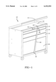
- FIG. 1 is a perspective view of an assembled storage unit utilizing the unique connectors of the present invention
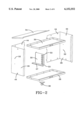
- FIG. 2 is an exploded perspective view of a storage unit utilizing the unique connectors of the present invention
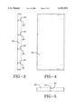
- FIG. 3 is a lengthwise elevation view of a top or bottom component of a storage unit utilizing the unique connectors of the present invention
- FIG. 4 is a plan view of the component of FIG. 3;
- FIG. 5 is a depthwise elevation view of the component of FIG. 3;
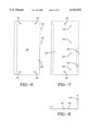
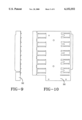
- FIG. 6 is a front elevation view of a wall component of the storage unit utilizing the unique connectors of the present invention.
- FIG. 7 is a right side view of the component of FIG. 6;
- FIG. 8 is a plan view of the component of FIG. 6;
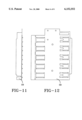
- FIG. 9 is a front elevation view of an inner panel of a storage unit ultilizing the unique connectors of the present invention.
- FIG. 10 is a right side elevation view of the panel of FIG. 9;
- FIG. 11 is a front elevation view of another inner panel of a storage unit utilizing the unique connectors of the present invention.
- FIG. 12 is a left side elevation view of the panel of FIG. 11;
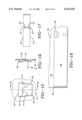
- FIG. 13 is a left side elevation view of a lock bar of a storage unit utilizing the unique connectors of the present invention.
- FIG. 14 is a front elevation view of the lock bar of FIG. 13;
- FIG. 15 is a cutaway view of a portion of the side component of FIG. 6 showing a connector of the present invention
- FIG. 16 is a sectional view taken along line 16--16 of FIG. 15;
- FIG. 17 is a cutaway view of a portion of the top or bottom component of FIG. 3;
- FIG. 18 is a cutaway view of the connection between the wall component of FIG. 6 and the top or bottom component of FIG. 3.
- FIG. 1 a perspective view of the storage container of the present invention is shown at 10.
- the storage unit 10 has three drawers 12 but it is to be appreciated that the storage unit may have more or less drawers as desired.
- a lid 14 may be used to provide a compartment on the top of the storage unit at 16.
- the storage unit preferably has a drop door 18 which secures a storage compartment behind the drop door.
- a lock bar 20 may be adapted to attach to the storage unit at 22 and may be locked at 24 through, for example, available means 25 with a hasp lock (not shown).
- the door lock bar 20 prevents unauthorized entry into the storage unit through the drop door 18, the drawers 12 and the lid 14.
- a portion 23 of the bar 20 would reside over the top of the lid 14 to prevent opening of the lid while the bar is in place.
- FIG. 2 is an exploded view of the storage unit 10 of FIG. 1 with the drawers 12 and the drop door 18, inter alia, removed from view.
- the storage unit 10 preferably has substantially identical wall components 26 that comprise the side and rear walls to the storage unit.
- a floor panel 28 and a top wall 30 are shown.
- a single inner panel 32 multiple inner panels may be needed in a given embodiment
- lid 34 and a caster 36 are also shown.
- FIGS. 3, 4 and 5 component 30 that can serve as both a top wall or a floor panel is shown.
- FIGS. 3 and 5 show receiving openings 40 and corresponding notches 42 that allow connection to the wall components 26 of the storage unit.
- FIGS. 6, 7 and 8 show a wall component 26.
- the wall component 26 has integral tabs 44 that interlock in the corresponding receiving openings 40 and notches 42 of FIGS. 3 and 5.
- FIG. 6 shows tabs 46 on the rear wall portion 48 that interlock into slots 50 of FIG. 7.
- FIG. 7 shows corner pockets 52 that receive the comers 54 of inner panels 32 (FIG. 2).
- FIGS. 9 and 10 show a left side inner panel 32 and FIGS. 11 and 12 show a right side inner panel 56.
- Inner panels 32 and 56 connect to respective right and left side walls of the storage unit 10 by corner pockets 52 of the wall component 26.
- the inner panels are adapted to slidably support drawers 12 within the storage unit 10. Additionally, the inner panels may have a drop door support 57 (shown in FIG. 2) attached to hingedly support a drop door 18.
- FIGS. 13 and 14 show a lock bar 20.
- the lock bar 20 is preferably configured with a bend 58 to be received into a portion of the floor panel at 22. The resulting connection may be viewed in FIG. 1 at 22.
- the upper portion of lock bar 20 has an opening 60 that is adapted to receive, for example, a lock hasp. Additionally, the top of lock bar 20 is designed to cover a portion of lid 14 at 23.
- FIGS. 15 and 16 show sectional and broken away views of an integral tab 44 in one of said walls.
- Tab 44 may be formed from the surrounding wall component material 64 by cutting an outer edge 66.
- the tab 44 may be formed from the wall component 26 and may be integral to that component along an edge 68. Alternatively, it is to be understood that tab 44 may be formed from a portion of either or both top wall 30 and floor panel 28.
- the tab 44 may be substantially parallel to the surface of the wall component 26 and may be offset therefrom, preferably just a fraction of an inch offset.
- a catch 70 may be formed from tab 44 by cutting along an edge 72 within the tab.
- the tab 44 may be bent along line 74, which may be along the integral edge of the catch 70 with the tab 44, to extend the distal end of the catch 70.
- FIG. 17 is a front view of a receiving opening 40 and notch 42 on a top wall 30 or a floor panel 28.
- Receiving opening 40 is adapted to receive the catch 70 of the tab 44 formed in the wall component 26.
- notch 42 may be formed in the top wall 30 or floor panel 28 to accommodate a portion of the integral edge 68.
- the material of the top wall 30 or floor panel 28 that is between the notch 42 and the receiving opening 40 serves as a catch lock for catch 70.
- FIG. 17 illustrates that top wall 30 or floor panel 28 preferably has a pair of oppositely disposed receiving openings 40 and notches 42. The first set is along edge 76 and the second set is along bend 78.
- FIG. 18 shows a completed connection between wall component 26 and floor panel 28.
- the wall component 26 is located behind the floor panel 28 and is connected at 80 and 82 to the floor panel.
- the connection is made by aligning the edge adjacent the receiving opening of the floor panel with the tab of the wall component.
- the floor panel catch lock is then pressed between the tab 44 and past the catch 70 until the catch 70 snaps into the receiving opening 401
- the tab 44 my be constructed of resilient material that allows the catch to be pressed toward the tab as the floor panel slides against the catch. Once the catch 70 is positioned within the receiving opening 40, a blunt end of the catch prevents the catch from leaving the receiving opening. Additionally, if the catch is of a resilient material, it may be biased into the receiving opening, thus preventing the blunt end of the catch from leaving the receiving opening.
- connection may be disconnected by pressing the catch out of the receiving opening until the blunt end of the catch 84 (see FIG. 16) clears the receiving opening.
- the floor panel may then be pulled apart from the wall component. Pressure against the catch may then be released.
Abstract
Description
Claims (1)
Priority Applications (1)
| Application Number | Priority Date | Filing Date | Title |
|---|---|---|---|
| US09/528,677 US6152552A (en) | 1995-02-21 | 2000-03-20 | Easy to assemble members |
Applications Claiming Priority (3)
| Application Number | Priority Date | Filing Date | Title |
|---|---|---|---|
| US08/391,211 US5645332A (en) | 1995-02-21 | 1995-02-21 | Easy to assemble storage unit |
| US08/815,317 US6039417A (en) | 1995-02-21 | 1997-03-10 | Easy to assemble storage unit |
| US09/528,677 US6152552A (en) | 1995-02-21 | 2000-03-20 | Easy to assemble members |
Related Parent Applications (1)
| Application Number | Title | Priority Date | Filing Date |
|---|---|---|---|
| US08/815,317 Continuation US6039417A (en) | 1995-02-21 | 1997-03-10 | Easy to assemble storage unit |
Publications (1)
| Publication Number | Publication Date |
|---|---|
| US6152552A true US6152552A (en) | 2000-11-28 |
Family
ID=23545731
Family Applications (3)
| Application Number | Title | Priority Date | Filing Date |
|---|---|---|---|
| US08/391,211 Expired - Fee Related US5645332A (en) | 1995-02-21 | 1995-02-21 | Easy to assemble storage unit |
| US08/815,317 Expired - Fee Related US6039417A (en) | 1995-02-21 | 1997-03-10 | Easy to assemble storage unit |
| US09/528,677 Expired - Fee Related US6152552A (en) | 1995-02-21 | 2000-03-20 | Easy to assemble members |
Family Applications Before (2)
| Application Number | Title | Priority Date | Filing Date |
|---|---|---|---|
| US08/391,211 Expired - Fee Related US5645332A (en) | 1995-02-21 | 1995-02-21 | Easy to assemble storage unit |
| US08/815,317 Expired - Fee Related US6039417A (en) | 1995-02-21 | 1997-03-10 | Easy to assemble storage unit |
Country Status (2)
| Country | Link |
|---|---|
| US (3) | US5645332A (en) |
| CA (1) | CA2170018C (en) |
Cited By (20)
| Publication number | Priority date | Publication date | Assignee | Title |
|---|---|---|---|---|
| WO2002017614A2 (en) * | 2000-08-18 | 2002-02-28 | Mitsubishi Digital Electronics America, Inc. | Foam cabinetry for electronic devices |
| US20040189159A1 (en) * | 2003-03-28 | 2004-09-30 | Metal Fabricating Corporation | Cabinet shelf securing members |
| US7065928B1 (en) * | 2003-10-09 | 2006-06-27 | Kcc International Inc. | Roof curb assembly |
| US20060138909A1 (en) * | 2004-12-23 | 2006-06-29 | Harry Chen | Panels with a connecting device |
| US20080122327A1 (en) * | 2006-11-29 | 2008-05-29 | Chieh-Ly Wu | Combination of cabinet and drawer |
| US20080173602A1 (en) * | 2006-07-19 | 2008-07-24 | Smurfit-Stone Container Enterprises, Inc. | Multi-shelf paperboard display unit and method of assembling the same |
| US20080185356A1 (en) * | 2007-02-06 | 2008-08-07 | Johan Orbeck Aase | Shelf system and shelf support element |
| US20080231150A1 (en) * | 2007-03-21 | 2008-09-25 | Larry Mitchell Grela | Toolbox assembly |
| US20080237169A1 (en) * | 2007-03-28 | 2008-10-02 | Gregory May | Portable display |
| US20080265728A1 (en) * | 2007-04-24 | 2008-10-30 | Collins James E | Boltless storage cabinet |
| US20090009041A1 (en) * | 2007-07-02 | 2009-01-08 | Octavian International Limited | Gaming machine and cabinets therefor |
| US20090102337A1 (en) * | 2007-10-17 | 2009-04-23 | Larry Mitchell Grela | Side cabinet and hutch system |
| US20100072716A1 (en) * | 2008-09-19 | 2010-03-25 | Larry Mitchell Grela | Portable tool storage assembly |
| US7934494B1 (en) * | 2003-10-10 | 2011-05-03 | Donna Gail Schneider | Collapsible heating apparatus |
| US20110181008A1 (en) * | 2010-01-28 | 2011-07-28 | The Stanley Works Israel Ltd. | Metal and plastic container |
| US8157337B2 (en) | 2009-06-16 | 2012-04-17 | Edwin Dizon Manalang | Tool box storage assembly |
| DE102011007445A1 (en) * | 2011-04-14 | 2012-10-18 | Fm Systemmöbel Franz Meyer Gmbh & Co. Kg | Anti-tilt device for attaching at cabinet for preventing overturning of cabinets of copiers, has guide portion for guiding anti-tilt device in direction of predetermined position below cabinet, where stopping portion is provided |
| DE102011050444A1 (en) * | 2011-05-17 | 2012-11-22 | Paul Hettich Gmbh & Co. Kg | Cabinet body i.e. tubular cabinet body, for suspended fastening at desk in office, has housing made of sheet metal and partially forming base and/or walls, frame fixed at walls and base, and retaining strips defined at each side wall |
| US20210195769A1 (en) * | 2019-12-19 | 2021-06-24 | Hongfujin Precision Electronics(Tianjin)Co.,Ltd. | Outer box and outdoor equipment with the same |
| US11912477B2 (en) | 2022-06-08 | 2024-02-27 | Yeti Coolers, Llc | Container with handle and latching system |
Families Citing this family (31)
| Publication number | Priority date | Publication date | Assignee | Title |
|---|---|---|---|---|
| DE19503801C1 (en) * | 1995-02-06 | 1996-05-30 | Siemens Nixdorf Inf Syst | Housing for data processing equipment |
| US5645332A (en) * | 1995-02-21 | 1997-07-08 | Stanley Mechanics Tools | Easy to assemble storage unit |
| US5984442A (en) * | 1997-05-07 | 1999-11-16 | The Durham Manufacturing Company | Cabinet and sliding drawer having improved features |
| US6074029A (en) * | 1997-11-19 | 2000-06-13 | The Stanley Works | Workstation and method of constructing the same |
| US5951129A (en) * | 1998-01-05 | 1999-09-14 | Stein; Brad A. | Tool-box |
| US6129366A (en) * | 1998-07-10 | 2000-10-10 | Wenger Corporation | Mobile teaching station |
| HU224861B1 (en) * | 1999-10-25 | 2006-03-28 | Andras Balogh | Storage unit made from cardboard |
| US6431376B1 (en) * | 2000-06-08 | 2002-08-13 | White Systems, Inc. | Storage bin assembly having unitary side and backwall supports |
| US20020185941A1 (en) * | 2001-06-11 | 2002-12-12 | Ferraro Frank A. | Moving cart assemblies |
| US6409293B1 (en) * | 2001-07-24 | 2002-06-25 | Ching-Chang Chang | Cabinet and drawer assembly structure |
| US20080129158A1 (en) * | 2006-11-30 | 2008-06-05 | Master Lock Company Llc | Storage case with internal frame |
| US20090140616A1 (en) * | 2007-12-04 | 2009-06-04 | Anthony Fox | Trash compactor cabinet |
| US20090145309A1 (en) * | 2007-12-05 | 2009-06-11 | Anthony Fox | Compactor with pivoting compaction plate |
| US7540234B1 (en) * | 2008-01-23 | 2009-06-02 | Buhl Hardwick Llc | Waste baling machine |
| CN102131990B (en) * | 2008-06-27 | 2013-12-25 | 梅特罗工业有限公司 | Improved sealing structure for sealing multiple sections and drawer of medical emergency cart |
| USD615325S1 (en) | 2009-02-17 | 2010-05-11 | Waterloo Industries, Inc. | Cabinet |
| USD613973S1 (en) | 2009-02-17 | 2010-04-20 | Waterloo Industries, Inc. | Cabinet |
| USD668078S1 (en) | 2009-02-18 | 2012-10-02 | Waterloo Industries, Inc. | Cabinet |
| USD670510S1 (en) | 2009-02-18 | 2012-11-13 | Waterloo Industries, Inc. | Cabinet |
| US20110234059A1 (en) * | 2010-03-22 | 2011-09-29 | Ellerbe Ii James L | System and method for toolbox |
| TWM433274U (en) * | 2012-02-29 | 2012-07-11 | ting-yu Zhang | Assembling structure of tool cabinet |
| CN106970688B (en) * | 2016-01-13 | 2019-12-06 | 纬创资通(中山)有限公司 | Server casing and plate joint structure |
| USD800279S1 (en) * | 2016-06-29 | 2017-10-17 | Get Kids Cooking Pty Limited | Portable kitchen work station with service components |
| USD891825S1 (en) | 2017-11-15 | 2020-08-04 | Newage Products Inc. | Cabinet |
| USD871114S1 (en) | 2017-11-15 | 2019-12-31 | Newage Products, Inc. | Cabinet |
| USD873587S1 (en) | 2017-11-15 | 2020-01-28 | Newage Products, Inc. | Cabinet |
| USD858119S1 (en) | 2017-11-15 | 2019-09-03 | Newage Products, Inc. | Cabinet |
| US10344791B2 (en) | 2017-11-28 | 2019-07-09 | Bsh Home Appliances Corporation | Minimal fastner assembly methodoligy |
| HUE053757T2 (en) * | 2018-12-19 | 2021-07-28 | Hilko Koch | System for transporting, handling and/or storage of goods |
| USD967656S1 (en) * | 2022-02-23 | 2022-10-25 | Luoyang Great Office Furniture Co., Ltd. | Folding storage cabinet |
| USD1007200S1 (en) * | 2023-04-07 | 2023-12-12 | Luoyang Selead Office Furniture Co., Ltd. | Tool trolley |
Citations (27)
| Publication number | Priority date | Publication date | Assignee | Title |
|---|---|---|---|---|
| US1557066A (en) * | 1921-02-14 | 1925-10-13 | Westinghouse Electric & Mfg Co | Box structure |
| US1646492A (en) * | 1925-04-29 | 1927-10-25 | Rauchbachgoldsmith Co | Locking bar for drawer-holding sections of wardrobe trunks |
| US2065282A (en) * | 1936-05-06 | 1936-12-22 | Howard U Herrick | Container seam |
| US2093199A (en) * | 1936-07-28 | 1937-09-14 | Continental Can Co | Side seam for sheet metal containers |
| US2147775A (en) * | 1938-05-20 | 1939-02-21 | Donald A Miller | Lock seam for pipe |
| US2201409A (en) * | 1938-05-04 | 1940-05-21 | Milcor Steel Company | Lock joint for sheet metal |
| US2259382A (en) * | 1940-10-14 | 1941-10-14 | Cincinnati Sheet Metal And Roo | Corner snap lock |
| US2740258A (en) * | 1952-12-06 | 1956-04-03 | Morris Machine Tool Company | Quill advancing and retracting device |
| US2916181A (en) * | 1954-10-06 | 1959-12-08 | Fed Pacific Electric Co | Sheet metal joint and box and method of making same |
| DE1149149B (en) * | 1957-03-09 | 1963-05-22 | Skaanska Aettikfabriken Ab | Cupboard for kitchen equipment |
| US3216426A (en) * | 1961-05-31 | 1965-11-09 | Rud Furrer Sohne A G | Collapsible file container |
| US3672531A (en) * | 1970-03-02 | 1972-06-27 | Emerson Electric Co | Receptacle |
| US3831799A (en) * | 1972-06-20 | 1974-08-27 | Teledyne Canada | Sheet metal panel assembly |
| US3856374A (en) * | 1974-03-18 | 1974-12-24 | Outers Laboratories | Knock-down electric food smoker |
| US4120551A (en) * | 1975-10-31 | 1978-10-17 | Krieg & Zivy Industries | Interlocking drawer assembly |
| US4243282A (en) * | 1979-02-22 | 1981-01-06 | Eastern Packaging And Display Co. | Knock down cabinet |
| US4463997A (en) * | 1982-06-07 | 1984-08-07 | Densen Mark S | Knockdown storage unit |
| US4479737A (en) * | 1982-02-01 | 1984-10-30 | Bergh Bros. Co., Inc. | Positive interlock |
| US4482074A (en) * | 1983-01-05 | 1984-11-13 | Lalley Donald P | Multipurpose container |
| US4561706A (en) * | 1981-12-04 | 1985-12-31 | Ograd S.R.L. | Hollow punched object for forming a structure with box walls |
| US4940155A (en) * | 1988-03-14 | 1990-07-10 | Hewson Kenneth E | Collapsible container |
| US5109985A (en) * | 1991-06-07 | 1992-05-05 | Formall/Blackwood Corporation | End cap locking means for a palletized container |
| US5246289A (en) * | 1990-02-05 | 1993-09-21 | Imperial Chemical Industries Plc | Agitator having streamlined blades for reduced cavitation |
| US5294196A (en) * | 1993-06-15 | 1994-03-15 | Tung I Enterprise Co., Ltd. | Tool cabinet |
| US5372269A (en) * | 1992-04-23 | 1994-12-13 | Creative Thermal Vac Manufacturing, Inc. | Multipurpose container and display sign |
| US5645332A (en) * | 1995-02-21 | 1997-07-08 | Stanley Mechanics Tools | Easy to assemble storage unit |
| US5669683A (en) * | 1993-09-30 | 1997-09-23 | Union Camp Corporation | Display shelf assembly |
-
1995
- 1995-02-21 US US08/391,211 patent/US5645332A/en not_active Expired - Fee Related
-
1996
- 1996-02-21 CA CA002170018A patent/CA2170018C/en not_active Expired - Fee Related
-
1997
- 1997-03-10 US US08/815,317 patent/US6039417A/en not_active Expired - Fee Related
-
2000
- 2000-03-20 US US09/528,677 patent/US6152552A/en not_active Expired - Fee Related
Patent Citations (28)
| Publication number | Priority date | Publication date | Assignee | Title |
|---|---|---|---|---|
| US1557066A (en) * | 1921-02-14 | 1925-10-13 | Westinghouse Electric & Mfg Co | Box structure |
| US1646492A (en) * | 1925-04-29 | 1927-10-25 | Rauchbachgoldsmith Co | Locking bar for drawer-holding sections of wardrobe trunks |
| US2065282A (en) * | 1936-05-06 | 1936-12-22 | Howard U Herrick | Container seam |
| US2093199A (en) * | 1936-07-28 | 1937-09-14 | Continental Can Co | Side seam for sheet metal containers |
| US2201409A (en) * | 1938-05-04 | 1940-05-21 | Milcor Steel Company | Lock joint for sheet metal |
| US2147775A (en) * | 1938-05-20 | 1939-02-21 | Donald A Miller | Lock seam for pipe |
| US2259382A (en) * | 1940-10-14 | 1941-10-14 | Cincinnati Sheet Metal And Roo | Corner snap lock |
| US2740258A (en) * | 1952-12-06 | 1956-04-03 | Morris Machine Tool Company | Quill advancing and retracting device |
| US2916181A (en) * | 1954-10-06 | 1959-12-08 | Fed Pacific Electric Co | Sheet metal joint and box and method of making same |
| DE1149149B (en) * | 1957-03-09 | 1963-05-22 | Skaanska Aettikfabriken Ab | Cupboard for kitchen equipment |
| US3216426A (en) * | 1961-05-31 | 1965-11-09 | Rud Furrer Sohne A G | Collapsible file container |
| US3672531A (en) * | 1970-03-02 | 1972-06-27 | Emerson Electric Co | Receptacle |
| US3831799A (en) * | 1972-06-20 | 1974-08-27 | Teledyne Canada | Sheet metal panel assembly |
| US3856374A (en) * | 1974-03-18 | 1974-12-24 | Outers Laboratories | Knock-down electric food smoker |
| US4120551A (en) * | 1975-10-31 | 1978-10-17 | Krieg & Zivy Industries | Interlocking drawer assembly |
| US4243282A (en) * | 1979-02-22 | 1981-01-06 | Eastern Packaging And Display Co. | Knock down cabinet |
| US4561706A (en) * | 1981-12-04 | 1985-12-31 | Ograd S.R.L. | Hollow punched object for forming a structure with box walls |
| US4479737A (en) * | 1982-02-01 | 1984-10-30 | Bergh Bros. Co., Inc. | Positive interlock |
| US4463997A (en) * | 1982-06-07 | 1984-08-07 | Densen Mark S | Knockdown storage unit |
| US4482074A (en) * | 1983-01-05 | 1984-11-13 | Lalley Donald P | Multipurpose container |
| US4940155A (en) * | 1988-03-14 | 1990-07-10 | Hewson Kenneth E | Collapsible container |
| US5246289A (en) * | 1990-02-05 | 1993-09-21 | Imperial Chemical Industries Plc | Agitator having streamlined blades for reduced cavitation |
| US5109985A (en) * | 1991-06-07 | 1992-05-05 | Formall/Blackwood Corporation | End cap locking means for a palletized container |
| US5372269A (en) * | 1992-04-23 | 1994-12-13 | Creative Thermal Vac Manufacturing, Inc. | Multipurpose container and display sign |
| US5294196A (en) * | 1993-06-15 | 1994-03-15 | Tung I Enterprise Co., Ltd. | Tool cabinet |
| US5669683A (en) * | 1993-09-30 | 1997-09-23 | Union Camp Corporation | Display shelf assembly |
| US5645332A (en) * | 1995-02-21 | 1997-07-08 | Stanley Mechanics Tools | Easy to assemble storage unit |
| US6039417A (en) * | 1995-02-21 | 2000-03-21 | The Stanley Works | Easy to assemble storage unit |
Non-Patent Citations (2)
| Title |
|---|
| Craftsman "Power & Hand Tools" Catalog, Jan. 1994. |
| Craftsman Power & Hand Tools Catalog, Jan. 1994. * |
Cited By (29)
| Publication number | Priority date | Publication date | Assignee | Title |
|---|---|---|---|---|
| WO2002017614A2 (en) * | 2000-08-18 | 2002-02-28 | Mitsubishi Digital Electronics America, Inc. | Foam cabinetry for electronic devices |
| WO2002017614A3 (en) * | 2000-08-18 | 2002-05-23 | Mitsubishi Digital Elect Usa | Foam cabinetry for electronic devices |
| US6545729B1 (en) * | 2000-08-18 | 2003-04-08 | Mitsubishi Digital Electronics America, Inc. | Foam cabinetry for electronic devices |
| US20040189159A1 (en) * | 2003-03-28 | 2004-09-30 | Metal Fabricating Corporation | Cabinet shelf securing members |
| US8827385B2 (en) * | 2003-03-28 | 2014-09-09 | Metal Fabricating Corporation | Cabinet shelf securing members |
| US7065928B1 (en) * | 2003-10-09 | 2006-06-27 | Kcc International Inc. | Roof curb assembly |
| US7934494B1 (en) * | 2003-10-10 | 2011-05-03 | Donna Gail Schneider | Collapsible heating apparatus |
| US20060138909A1 (en) * | 2004-12-23 | 2006-06-29 | Harry Chen | Panels with a connecting device |
| US20080173602A1 (en) * | 2006-07-19 | 2008-07-24 | Smurfit-Stone Container Enterprises, Inc. | Multi-shelf paperboard display unit and method of assembling the same |
| US7882966B2 (en) * | 2006-07-19 | 2011-02-08 | Smurfit-Stone Container Enterprises, Inc. | Multi-shelf paperboard display unit and method of assembling the same |
| US20080122327A1 (en) * | 2006-11-29 | 2008-05-29 | Chieh-Ly Wu | Combination of cabinet and drawer |
| US20080185356A1 (en) * | 2007-02-06 | 2008-08-07 | Johan Orbeck Aase | Shelf system and shelf support element |
| US7784887B2 (en) * | 2007-03-21 | 2010-08-31 | Larry Mitchell Grela | Toolbox assembly |
| US20080231150A1 (en) * | 2007-03-21 | 2008-09-25 | Larry Mitchell Grela | Toolbox assembly |
| US20080237169A1 (en) * | 2007-03-28 | 2008-10-02 | Gregory May | Portable display |
| US8042890B2 (en) * | 2007-04-24 | 2011-10-25 | Edsal Manufacturing Co., Inc. | Boltless storage cabinet |
| US20080265728A1 (en) * | 2007-04-24 | 2008-10-30 | Collins James E | Boltless storage cabinet |
| US20090009041A1 (en) * | 2007-07-02 | 2009-01-08 | Octavian International Limited | Gaming machine and cabinets therefor |
| US20090102337A1 (en) * | 2007-10-17 | 2009-04-23 | Larry Mitchell Grela | Side cabinet and hutch system |
| US20100282629A1 (en) * | 2007-10-17 | 2010-11-11 | Larry Mitchell Grela | Side cabinet and hutch system |
| US20100072716A1 (en) * | 2008-09-19 | 2010-03-25 | Larry Mitchell Grela | Portable tool storage assembly |
| US8157337B2 (en) | 2009-06-16 | 2012-04-17 | Edwin Dizon Manalang | Tool box storage assembly |
| US20110181008A1 (en) * | 2010-01-28 | 2011-07-28 | The Stanley Works Israel Ltd. | Metal and plastic container |
| US10022856B2 (en) * | 2010-01-28 | 2018-07-17 | The Stanley Works Israel Ltd. | Metal and plastic container |
| DE102011007445A1 (en) * | 2011-04-14 | 2012-10-18 | Fm Systemmöbel Franz Meyer Gmbh & Co. Kg | Anti-tilt device for attaching at cabinet for preventing overturning of cabinets of copiers, has guide portion for guiding anti-tilt device in direction of predetermined position below cabinet, where stopping portion is provided |
| DE102011050444A1 (en) * | 2011-05-17 | 2012-11-22 | Paul Hettich Gmbh & Co. Kg | Cabinet body i.e. tubular cabinet body, for suspended fastening at desk in office, has housing made of sheet metal and partially forming base and/or walls, frame fixed at walls and base, and retaining strips defined at each side wall |
| US20210195769A1 (en) * | 2019-12-19 | 2021-06-24 | Hongfujin Precision Electronics(Tianjin)Co.,Ltd. | Outer box and outdoor equipment with the same |
| US11665838B2 (en) * | 2019-12-19 | 2023-05-30 | Fulian Precision Electronics (Tianjin) Co., Ltd. | Outer box and outdoor equipment with the same |
| US11912477B2 (en) | 2022-06-08 | 2024-02-27 | Yeti Coolers, Llc | Container with handle and latching system |
Also Published As
| Publication number | Publication date |
|---|---|
| US5645332A (en) | 1997-07-08 |
| US6039417A (en) | 2000-03-21 |
| CA2170018A1 (en) | 1996-08-22 |
| CA2170018C (en) | 2001-11-27 |
Similar Documents
| Publication | Publication Date | Title |
|---|---|---|
| US6152552A (en) | Easy to assemble members | |
| US4887874A (en) | Knockdown drawers and bins | |
| EP1932448B1 (en) | Corner fitting | |
| US8042890B2 (en) | Boltless storage cabinet | |
| US4295693A (en) | Knocked-down cabinet | |
| US4744445A (en) | Case assembly kit | |
| US5738462A (en) | Locking clip system for securing panels together | |
| EP0564507A1 (en) | Interlockable structural members and double wall containers assembled therefrom | |
| US11944192B2 (en) | Modular furniture system | |
| US4095698A (en) | Modular storage rack system | |
| US5597221A (en) | Drawer assembly having interlocking members | |
| EP0683102A1 (en) | Receptacle and blank therefor | |
| US4469273A (en) | Self-unlocking container closure | |
| WO1982000624A1 (en) | Disposable suitcase | |
| US4350257A (en) | Kit for assembling toolbox adapted for installation in back of pickup truck and method of assembling the toolbox | |
| US6422672B1 (en) | Frameless appliance garage adapter | |
| US5876276A (en) | Collapsible chimney cap | |
| US20050023942A1 (en) | Steel cabinet drawer file | |
| US3352474A (en) | Recessed end carton | |
| US4280622A (en) | Tapered insert | |
| JP2743629B2 (en) | Assembled storage furniture | |
| US3377090A (en) | Connection for resilient deformable panels | |
| GB2340480A (en) | Modular box with releasable fastenings | |
| US5833111A (en) | Foldable storage container | |
| EP0697180B1 (en) | A document holder |
Legal Events
| Date | Code | Title | Description |
|---|---|---|---|
| AS | Assignment |
Owner name: STANLEY WORKS, THE, CONNECTICUT Free format text: ASSIGNMENT OF ASSIGNORS INTEREST;ASSIGNOR:STANLEY MECHANICS TOOLS;REEL/FRAME:011269/0364 Effective date: 19971217 Owner name: STANLEY MECHANICS TOOLS, OHIO Free format text: ASSIGNMENT OF ASSIGNORS INTEREST;ASSIGNORS:SNOKE, STEVEN R.;SILVIS, GARY;HOWLAND, THOMAS E.;REEL/FRAME:011269/0416 Effective date: 19950216 |
|
| FPAY | Fee payment |
Year of fee payment: 4 |
|
| REMI | Maintenance fee reminder mailed | ||
| LAPS | Lapse for failure to pay maintenance fees | ||
| STCH | Information on status: patent discontinuation |
Free format text: PATENT EXPIRED DUE TO NONPAYMENT OF MAINTENANCE FEES UNDER 37 CFR 1.362 |
|
| FP | Expired due to failure to pay maintenance fee |
Effective date: 20081128 |