US6152563A - Eye gaze direction tracker - Google Patents
Eye gaze direction tracker Download PDFInfo
- Publication number
- US6152563A US6152563A US09/027,511 US2751198A US6152563A US 6152563 A US6152563 A US 6152563A US 2751198 A US2751198 A US 2751198A US 6152563 A US6152563 A US 6152563A
- Authority
- US
- United States
- Prior art keywords
- eye
- user
- glint
- pupil
- computer
- Prior art date
- Legal status (The legal status is an assumption and is not a legal conclusion. Google has not performed a legal analysis and makes no representation as to the accuracy of the status listed.)
- Expired - Lifetime
Links
Images


Classifications
-
- G—PHYSICS
- G06—COMPUTING; CALCULATING OR COUNTING
- G06F—ELECTRIC DIGITAL DATA PROCESSING
- G06F3/00—Input arrangements for transferring data to be processed into a form capable of being handled by the computer; Output arrangements for transferring data from processing unit to output unit, e.g. interface arrangements
- G06F3/01—Input arrangements or combined input and output arrangements for interaction between user and computer
- G06F3/011—Arrangements for interaction with the human body, e.g. for user immersion in virtual reality
- G06F3/013—Eye tracking input arrangements
-
- A—HUMAN NECESSITIES
- A61—MEDICAL OR VETERINARY SCIENCE; HYGIENE
- A61B—DIAGNOSIS; SURGERY; IDENTIFICATION
- A61B3/00—Apparatus for testing the eyes; Instruments for examining the eyes
- A61B3/10—Objective types, i.e. instruments for examining the eyes independent of the patients' perceptions or reactions
- A61B3/113—Objective types, i.e. instruments for examining the eyes independent of the patients' perceptions or reactions for determining or recording eye movement
-
- G—PHYSICS
- G06—COMPUTING; CALCULATING OR COUNTING
- G06V—IMAGE OR VIDEO RECOGNITION OR UNDERSTANDING
- G06V40/00—Recognition of biometric, human-related or animal-related patterns in image or video data
- G06V40/10—Human or animal bodies, e.g. vehicle occupants or pedestrians; Body parts, e.g. hands
- G06V40/18—Eye characteristics, e.g. of the iris
- G06V40/193—Preprocessing; Feature extraction
Definitions
- This invention describes an eye-gaze direction detecting device which is utilized as a means of interfacing a person with a computer.
- the present invention is an improvement over the invention disclosed in U.S. patent application Ser. No. 267,266 filed on Nov. 4, 1988 now U.S. Pat. No. 4,950,069 which disclosure is hereby incorporated herein and made a part hereof.
- the improvement relates to a new calibration arrangement granting greater accuracy, better algorithms that allow a more robust determination of pupil-glint displacement, and features that allow an operator to effectively exploit a graphical user interface (GUI).
- GUI graphical user interface
- eye-gaze direction detector refers generically to any technology related to detecting either movement of the eye or eye-gaze direction.
- One of the eye movement technologies is electrooculography, which uses the difference in voltage between the cornea and the retina of the eye.
- corneal reflection which uses the reflection of a beam of light from the various surfaces of the eye the beam crosses.
- the brightest reflection is the outer corneal surface (first Purkinje image) with the second, third, and fourth Purkinje images being dimmer and corresponding respectively to the inner surface of the cornea and the outer and inner surfaces of the lens.
- first Purkinje image the outer corneal surface
- third, and fourth Purkinje images being dimmer and corresponding respectively to the inner surface of the cornea and the outer and inner surfaces of the lens.
- the reflections from the outer surface of the cornea and the inner surface of the lens are the two utilized.
- a third technology is limbus tracking that detects the generally sharp boundary between the iris and the sclera (the white part of the eye).
- a fourth technology is the use of a contact lens that rotates with the eye and is fitted with various devices to determine the amount of eye rotation.
- a fifth technique is to measure the eccentricity of the pupil which varies from circular when viewed head on to elliptical as it rotates away from the axis in which it is viewed.
- a sixth technique is a movement measurement based on the head and eyes being moved together.
- a seventh technique is the oculometer that determines the center of the pupil and the corneal highlight from a reflected light and the change in the distance and direction between the two as the eye is rotated. Additional techniques exist, but these are the major ones. Some of them incorporate a head or eye mounted devices whereas others permit the eye-gaze direction detector to be mounted remote to the head.
- the present invention relates specifically to the category of oculometer eye measurement detectors but some aspects of the invention can also be utilized with other techniques.
- the invention is primarily designed to provide an eye-driven method of interfacing a person with the computer. This is of fundamental interest to handicapped individuals who would benefit greatly from an eye-driven device. When a healthy functional person suddenly loses their ability to act for themselves and to communicate, the mind becomes trapped within the body. The need to communicate and remain productive becomes more acute for the individual when they are robbed of motor functions and speech.
- Complete motor dysfunction occurs as a result of both traumatic spinal injuries and gradual paralysis during the course of peripheral neuromuscular diseases. It affects young children by making them grow up in mental and physical isolation without a way to educate their minds or to acquire skills for an adult life. It also affects adults who are accustomed to a normal lifestyle and who must learn to cope with the resulting severe form of isolation from family, friends, and others who must now care for them.
- the invention has been primarily developed for handicapped persons, the technology may also be used for industrial control, cockpit control, video game control, workstation control, and other applications where eye-gaze control is desired.
- the invention may also be used for testing and training purposes based on eye movement, such as testing or training radiologists to read x-rays.
- the eye normally directs its gaze with a very high degree of accuracy at the gaze point. This is due to the photoreceptors of the human retina not being uniformly distributed but instead show a pronounced density peak in a small region known as the fovea. In this region, which subtends a visual angle for about 1°, the receptor density increases to about 10 times the average density.
- the nervous system controls the muscles attached to the eye to keep the image of the region of current interest centered accurately on the fovea as this gives the high resolution.
- the appearance of high resolution at all directions outside of this region is thus an illusion maintained by a combination of physiological mechanisms (rapid scanning with brief fixations), and psychological ones.
- a character on a typical computer display screen subtends an angle of about 0.3° at a normal viewing distance. Such characters cannot be accurately resolved unless the eye is accurately aligned for a duration of 0.2 seconds.
- the eye-gaze direction detecting system described here is designed to allow control over the computer through dwell time activation of commands normally controlled by mouse clicks. By fixating on an area of the computer display, the system performs a user selected mouse action at that position, thus granting the user the same control over the computer that is allowed by a conventional mouse.
- the main components of the system include a charge-coupled device (CCD) camera sensitive to the near infrared with a 300 mm zoom lens and a coaxially mounted infrared light source.
- CCD charge-coupled device
- An infrared filter allows primarily infrared light to reach the camera.
- This assembly is housed inside a module that rests beneath the computer monitor.
- the module employs a folded optical arrangement that directs the camera's line of sight to the user's eye through the use of two mirrors. This keeps the system relatively small and unobtrusive.
- One of the primary advantages of the system is that it does not require any devices to be fixed to body of the user.
- the camera is coupled to an inexpensive computer that contains a frame grabber or image processing board.
- the board digitizes video images of the eye acquired by the video camera, and the algorithms forming a part of this invention then process the image.
- the operant image consists of a video image encompassing one side of the user's face. It contains the iris and sclera (both dark), the reemission of the infrared light out of the pupil (bright eye), and the corneal reflection of the infrared light source (glint).
- An in-focus bright eye image gives a high contrast boundary at the pupil perimeter making it easily distinguishable.
- the system computes the relative x-y coordinates between the glint center and the pupil center as determined by the pattern recognition software incorporated in this patent.
- One of the improvements to the pattern recognition software is the inclusion of algorithms that enable individuals with glasses to use the system. Glasses create extraneous reflections from the rims and lenses (glares). These reflections can possibly make pupil and glint identification difficult. The new improvements essentially remove a majority of these added reflections from the image thereby allowing individuals with glasses to benefit from an eye-controlled device.
- the glint and the bright eye are features produced by the infrared light emitted by the semiconductor diode, mounted coaxial with the video camera lens.
- the illumination is invisible to the user and has a principle advantage of producing very little subject awareness of the monitoring process. Since the light source is in coaxial alignment with the video camera lens, it results in light re-emitted back from the retina which effectively backlights the pupil so that it appears as a bright disk. This is the bright eye effect and provides a distinctive contrast to the rest of the eye or facial details. This greatly facilitates the determination of the periphery of the pupil so that the center of the pupil can be accurately calculated, which is an important feature in an oculometer. The system measures the differential between the pupil center and glint center and uses this data to compute where the eye is gazing.
- the system detects when the eye lingers for a predetermined period at any position on the display. If the predetermined linger period is exceeded, then the system magnifies the area the user was looking at. A window at or near the center of the screen appears and the magnified area is placed in this window. The user then fixates in the magnified area at a point where they wish for a mouse action to be performed. After the predetermined fixation period has expired, a menu appears that allows the user to select what mouse action they wish to perform--left mouse button drag, left mouse button single click, left mouse button double click, right mouse button drag, right mouse button single click, or right mouse button double click. After fixating on the menu command for a predetermined amount of time, the system then performs the desired mouse action at the position fixated on in the magnified area.
- the present invention determines eye gaze position using effects generated by infrared light.
- An infrared light emitting diode mounted at the center of the video camera lens illuminates the user's face with infrared light.
- a small fraction of the light entering the eye is absorbed and re-emitted by the retina, creating an image that is the same phenomenon which causes the pink eye effect in photography where the flash bulb is located close to the optical axis of the camera.
- it causes the pupil to be brighter than the rest of the eye whereas it is usually darker than the remainder of the eye.
- the cornea reflects an intense virtual image of the light emitting source and is referred to as the glint.
- the glint is usually located within the pupil's image or along or near its outer circumference.
- the computer contains a frame grabber card that is commercially available and captures a frame of the video camera as a 640 ⁇ 480 ⁇ 8 bit frame.
- the pattern recognition software of the present invention calculates eye-gaze direction by determining the distance and angle between the glint center and pupil center. To do this, the system first obtains the intensity thresholds between the glint and the surrounding portions of the eye and then between the pupil and the surrounding portions of the eye. This step is called threshold setting. Upon completing threshold setting, the system may then accurately calculate the displacement measurements between the glint and pupil center. To effectively control the computer, the user must undergo the next step, calibration.
- Completion of this step which entails the user looking at a sequence of fixed points on the screen, allows the software to map a particular glint-pupil displacement to a particular point on the screen.
- the user may operate the computer using solely their eye.
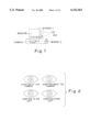
- FIG. 1 shows the equipment used and the optical path of the system.
- FIG. 2 describes how the glint-pupil relationships change as the user looks at different positions on the screen.
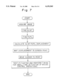
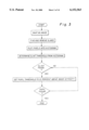
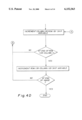
- FIG. 3 is a flowchart for the basic procedure used in the threshold determination algorithm.
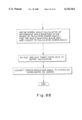
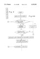
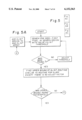
- FIG. 4 describes the glare removal algorithm.
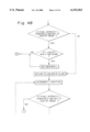
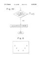
- FIG. 5 shows how the glint center is determined.
- FIG. 6 shows the six point calibration layout.
- FIG. 7 shows how the system identifies features in the actual operation of the system.
- FIG. 8 describes how the system maps the glint-pupil displacement to a particular position on the screen.
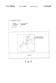
- FIG. 9 shows how the zooming feature with the system works.
- FIG. 10 shows the menu for activating mouse control actions.
- FIG. 1 shows the setup of the system.
- the setup includes a standard computer display resting on top of a module that houses the eye-tracking equipment. Two mirrors on the module direct the camera's line of sight to the user's eye.
- the computer display sits so that the image of the camera in the mirror is at the center horizontally of the computer display.
- the infrared light emitting source is a readily available gallium arsenide diode. They are approximately 1 to 3 cm in diameter and are normally used for communication purposes with a narrow light beam dispersion as opposed to some types that send light in all directions and are used mainly as indicator lights. They usually have a small built in molded clear lens that condenses the light into a narrow beam. Additionally, the diode is placed in a plastic tube that serves to condense the beam further and to ensure that the infrared light striking the eye does so by following the optical path shown in figure one and not by bypassing the mirrors altogether. This would give a double glint in the camera image and decrease the reliability in determining the proper glint-pupil displacement.
- the diode preferred emits a focussed beam of light at a wavelength of 880 nm, but wavelengths as high as 900 nm are acceptable. This wavelength is invisible to the user and of a sufficiently low intensity such that it is safe for continuous use by the operator.
- the diode is mounted at the center of a filter screwed onto the lens. This filter blocks most visible light, allowing the infrared to pass through with little decrease in intensity.
- the secondary monitor normally placed by the side of the computer monitor shows the eye image seen by the camera and allows the user to ensure that they are in focus and properly positioned in front of the video camera.
- FIG. 2 describes qualitatively the glint-pupil relationships seen as the user gazes at different positions on the display.
- the glint is approximately at the pupil's center. As they look directly above the camera, the glint center drops below the pupil center.
- the glint center moves to the left, so the glint is to the bottom left of the pupil center.
- the glint center moves to the right of the pupil center.
- Matrox Meteor frame grabber card Installed inside the computer is a Matrox Meteor frame grabber card that acquires images from the video camera, but any compatible frame grabber card will do.
- the card uses the RS-170 standard to acquire an image, digitizes it into a sequence of pixels, and maps those pixel values into system memory. This results in a 640 ⁇ 480 resolution image with each pixel having a value from 0 to 255, with 0 being black and 255 being white. The intensity values in between represent different shades of gray.
- ERICA HQ is the software program that provides an interface for manipulating the setup of the eye-controlled mouse and for undergoing calibration and threshold setting.
- the first step in using the system is to set thresholds; the basic procedure is outlined in FIG. 3.
- the object of this stage is to obtain the minimum intensity values of the glint and pupil so that the software may quickly identify both of these features during calibration and actual system operation.
- the user looks directly back into the center of the camera, focusing on the image of the light emitting diode (LED) seen in the top mirror.
- the system snaps an image and maps it into memory.
- the origin of the camera coordinate system is the upper-left comer of the camera image.
- the x coordinates increase as the system moves to the right.
- the y coordinates increase as the system moves down in the image.
- the first parameter, search scheme specifies whether the software searches horizontally or vertically when trying to find the boundary of a glare.
- a third setting has the software perform two passes; one searching for glares horizontally first, then searching for the glares vertically.
- This last method maximizes the reduction of the glares but does slow system processing down.
- Two additional parameters specify how many lines to skip vertically and how many to skip horizontally as glare detection proceeds through the image. The more lines skipped, the less efficiently the system will remove the glares, but the less time will expire before the glare removal algorithm completes its task.
- Another parameter is the glare threshold, which is the intensity value above which a pixel could potentially be considered part of a glare.
- Another is the pixel length of the glare, which defines the number of pixels in succession that must be found greater than the glare threshold for a region of the image to be considered a glare.
- a glare generally has the same or higher intensity than a glint, but the glare is larger.
- the system starts by moving to the right of the current sequence of pixels it believes to be part of a glare.
- the system checks each pixel as it advances to the right and stops its check when it either reaches the edge of the screen or finds a pixel whose intensity is below the glare threshold.
- the software checks to the left, again advancing left until it either reaches the screen edge or finds a pixel whose intensity is below the glare threshold.
- the system decrements its y value and checks to the left and right again. After an upper bound has been reached (the pixel value at the new y coordinate is below the threshold or the screen edge is reached), then the system increments its y value to find the bottom of the rectangle.
- the overall minimum and maximum x values are stored. After the bottom of the rectangle is found, then the system has found both the minimum and maximum x and y values for the glare, so the glare is ready for removal, and the glare threshold is returned to its old value.
- the system begins its search for the glares in the upper left-hand corner of the camera image. If any glares were found, then the system removes the glares by turning every pixel in the glare's bounding rectangle black. Glare removal is fast and has the advantage of decreasing the number of areas that the feature finding algorithms will query to attempt to identify the glint and pupil. Upon removing the glares, the system is now ready to attempt to set the thresholds (minimum intensity values) for the glint and pupil.
- the first step is to determine a glint threshold.
- the system first makes a histogram of the intensity values for each pixel of the camera image.
- the intensity values range from 0 to 255, so there are 256 buckets.
- the number of pixels with an intensity value equal to the value of the bucket is stored in each bucket.
- the lowest and largest hump would represent data that shows the intensity values of the face.
- the next highest hump would represent data for the bright eye and a spike near the highest intensity values would show an intensity value for the glint.
- the system To determine a starting threshold for the glint, the system begins at the end of the histogram (intensity value 255) and moves backward to each bucket, summing the value in each bucket. Once a value of twenty pixels is reached, the system sets the current bucket number to be the threshold for the glint.
- FIG. 5 shows a flowchart representing how a glint center is found. This is the same algorithm used to determine the glint center in calibration and runtime operation of the system.
- the first step to finding a glint is to find a seed point, which is the pixel that serves as the starting point for attempting to find the glint's bounding rectangle.
- the system scans the search region to find the first pixel whose intensity value is greater than the glint threshold. If a seed is found but it is in the seed point memory array, which serves as a buffer containing the locations of all invalid glints, then it is ignored.
- the search region is either the entire image if the system is in a global search mode or a region of 180 ⁇ 180 pixels centered on the last valid glint if the system is in the local search mode.
- the system tries to find an upper bound on the glint.
- the system decrements its y counter by one pixel. It then tries to find the minimum and maximum x coordinates for the glint with the current y value.
- the system checks each pixel to the left and right and stops its check once it finds a pixel with an intensity value lower than the threshold.
- the system stores the overall maximum and minimum x coordinates of the glint's bounding rectangle for all lines checked. This process of checking each line is called filling.
- a filling error occurs when the system reaches the edge of the camera image and all the pixels checked are still above the threshold value.
- the system tries to find a valid lower bound of the glint if the upper bound was found without error. This follows the same algorithm as far as filling is concerned. The only difference is that the y counter is being incremented.
- the system determines the glint diameter, center, and aspect ratio.
- the diameters are calculated based on the maximum and minimum x and y coordinates.
- the aspect ratio is the ratio of the x diameter to the y diameter. All three of these values are checked against preset values and tolerances to ensure that a proper glint is found--that its shape belongs to a valid glint. For example, the glint's bounding rectangle should be approximately a square, so an aspect ratio that is too far above or below the value of one would signify an erroneous glint. If these three checks pass, then the system calculates the center of mass of the glint.
- the system sums the number of pixels in the glint, and the x coordinates of valid glint pixels are summed as well as the y coordinates.
- the x coordinate of the center of mass is the x sum divided by the number of pixels and the y coordinate is the y sum divided by the number of pixels.
- the software performs the glint error handling routine as described below and attempts to find another glint. If no seed was found, then decrement the threshold by 10 units. If the glint threshold goes below the average image intensity, then snap a new image and restart the threshold setting procedure.
- the glint error handling routine shown consists of a feature called seed point memory. This is a new innovation with the system that keeps it from bouncing between potential glints. Once a glint is found to be erroneous, then its bounding rectangle is added to the seed point memory. The system will then ignore any seed points that it finds in these regions while it attempts to analyze the present image. Once a new image is snapped, then this memory is cleared.
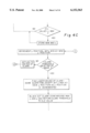
- the system sets an initial approximation for the pupil threshold. This value is set at 10 percent above the average image intensity.
- the software tests the threshold by attempting to find a pupil.
- the algorithm used is the same as the one used for the glint, except the system checks pixel intensities relative to the pupil threshold. If no pupil is found due to not being able to find a seed, then we are not looking at the correct glint. Perhaps the system is trying to bound some other reflection from the eye or a small glare escaped elimination.
- the software performs the glint error handling routine and tries to find a new glint. If the fill routines failed, then the pupil threshold might be too low, so try setting a higher threshold. The pupil threshold is increased by 10 percent, and the system tries to find the pupil again.
- this step has already occurred, then we are searching around a bad glint so perform the glint error handling routine and try to find a new glint.
- the system checks that there are not too many pixels in the pupil greater than the glint threshold. If this test fails, then the pupil found is not the true pupil, so the system performs the glint error handling routine and tries to find a new glint. If the pupil is found, then the system then tries to relocate the pupil after making the threshold 90 percent of the current average pupil intensity. The system uses a different routine to now find the pupil. This is the method used in the runtime operation of the system.
- This routine is essentially the same as the one used to find the glint, except the system will try to find the pupil several times before failing this section of the routine. Basically, if the pupil center determination fails, then the search region is adjusted based on the previously found max of the pupil; the new x starting position is set to the pupil x max and the y starting position is set to the pupil seed's y value plus 1.
- the initial search region for the pupil seed is a rectangle that is 30 pixels by 10 pixels and centered at 5 pixels above the potential glint's center. If the pupil cannot be found, then the glint is bad so perform the glint error handling routine and try to find a new glint.
- the system has now found valid thresholds.
- One of the improvements in the system is the use of dynamic thresholding, which means the threshold values used to define the minimum glint and pupil intensity are constantly updated as the system operates to provide more accurate bounds on the features during runtime. So, the software will now setup the minimum allowed pupil and glint thresholds, which are set to 2/3 of the current threshold for the respective feature, ensuring that the minimum glint threshold is not below the current pupil intensity. Also, the system stores the current threshold to use as a reset point if the feature threshold ever gets adjusted too far. The system also stores the current glint intensity relative to pupil intensity to serve as an additional check during calibration and runtime. Lastly, minimum and maximum glint and pupil sizes are set based on the current features sizes.
- An innovation added to this invention is the storage of the x and y offsets of the pupil center from the glint center that occurs as the user looks back into the camera. All of the mathematical models used in calibration and the discussions so far have assumed that the glint center is truly at the pupil center when the user looks back into the center of the camera; however, this is not the case for everyone. Thus, in subsequent determinations of the glint-pupil displacement, the system will subtract these stored offsets from the calculated x-y glint-pupil displacement before converting to the polar coordinates used by the calibration equations. This compensation more than doubles system accuracy for the typical user, granting them a consistent accuracy over the entire computer display. This increases the proportion of the population that can effectively use the system to control the GUI.
- the user looks at the bottom of the computer display.
- the above algorithm is repeated, except the glint-pupil offset is not stored.
- This stage is necessary because the pupil is usually at a lower intensity when looking at the bottom of the screen than when looking directly back to the camera, and the pupil threshold needs to be set at the lowest possible valid value.
- Calibration is the process of determining the equations used to map angles and radii between the pupil and glint centers of the user's eye to radii and angles on the screen, with the origin of the coordinate system for the screen being just below the bottom center of the monitor's screen. To determine these equations, the user fixates on a sequence of calibration points shown on the computer display as either a dot or a picture of some type. Calibration is essential to achieving good accuracy with the system. No matter how well the system determines the pupil and glint centers, if the regression equations are faulty, then the accuracy will be poor.
- the current calibration algorithm sets up calibration points at fixed angles and radii from the origin of the monitor's coordinate system.
- the resulting configuration is a web of points expanding from just below the bottom center of the monitor's screen.
- Each radial line, a line of calibration points at a fixed angle from the monitor origin performs its own linear regression for determining the equation used to map a radius between the pupil and glint center to a radius on the screen.
- Each arc of a constant radius performs its own linear regression for determining the equation used to map an angle between the pupil and glint center to an angle on the screen.
- the calibration procedure consists of the user fixating on each calibration point as the system shows each point one at a time. While the user fixates on the point, the software is snapping images and identifying glint-pupil displacements using the methods described above to determine the glint and pupil center. Note that these displacements are corrected by the glint pupil offset found during the first stage of threshold setting.
- the system tries to obtain ten valid displacements for each calibration point.
- the software then computes the median value for the ten samples and discards any samples that are too far away from the median; if the computed radius for a sample is more than one pixel from the median or if the computed angle for a sample is more than two degrees from the median, then the sample is considered erroneous.
- An average glint-pupil displacement is then determined by averaging the displacements of the remaining samples. If five or more samples are thrown out or ten valid samples cannot be obtained, then the system attempts to recalibrate the point. If the point fails calibration three times, then the software moves on to the next point and removes the calibration point from the linear regression algorithm.
- the system determines a sequence of equations to map a particular glint-pupil vector to the screen. Once all calibration points have been completed, then the system uses a linear regression to calculate these equations. The system tries to find the best-fit linear line through the points corresponding to the different radii and angles that maximizes the correlation coefficient. If this value is too low or only two points went into the regression (a linear regression can always determine a line through two points), then the system will signal to the user that some of the points may need recalibrating if they wish to obtain better accuracy.
- the software has a method that allows the user to recalibrate only the points that caused the regressions to fail.
- the user may then enable the system through the HQ interface. If mouse emulation is enabled, then the mouse cursor will follow where the user is looking.
- the software uses the algorithm shown in FIG. 7.
- HQ allows the user to specify the sampling rate--the frequency at which the system acquires an image and attempts to determine where the user is looking.
- a higher sampling rate burdens the system more, but delivers more data to the operating system.
- Even with the maximum sampling rate of 15 samples per second, effective control over the computer is possible with little degradation of system performance; however, when using a processor intensive application like a video game, the sampling rate might need to be reduced to improve performance.
- a timer starts that signals the system to acquire images at a frequency corresponding to the sampling rate.
- the software uses the routines described above to determine the bounding rectangle for both the glint and the pupil.
- the system has two searching modes--local and global search.
- a global search attempts to find the glint at any region in the camera image.
- a local search centers the searching region on the previously determined valid glint; in essence, the system is assuming the user is sitting in the same position. Local searching greatly reduces the processing that must occur for the system to identify valid features, as a user's position typically does not vary much between successive frames.
- the system dynamically adjusts the glint threshold in an attempt to find the correct glint. If a filling error occurred, such as the system believing the glint was at the edge of the camera screen, then the system simply performs the glint error handling routine and jumps to a global search. If no seed was found, then the search region was exhausted, so it is time to adjust the glint threshold. If the bound on the bad glint resulted in a glint too big, then the threshold is increased by 5 pixel intensity units, which range from a value of 0 to 255. If the glint was too small, then the threshold is decreased.
- the system checks the search mode. If a local search is being conducted, then the threshold is decreased. If this occurs too many times, then the search mode is changed to global search. If a valid glint cannot be found globally, then the system simply waits. If three frames pass with no valid glint, then the threshold is reduced. If the threshold is reduced below the minimum threshold value for the glint, then tracking is failed for the image, and the thresholds are reset.
- the system jumps to a global search mode and performs the glint error handling routine and tries to find a new glint.
- the system performs a few additional checks before calculating gaze position.
- the software checks the glint intensity relative to the pupil intensity. If this ratio is too small (as compared to the minimum set in threshold setting), then the glint detected is really most likely part of the pupil, so the glint threshold is increased and the system attempts to find a new glint.
- the system checks that the glint center is not above the pupil center. During operation of a computer, the glint center will never be above the pupil center, so if it is, then an erroneous glint was found, so the glint error handling routine occurs, a global search for the glint is initiated, and the threshold is reduced.
- the system checks the counter for the number of pixels in the pupil greater than the glint's threshold. If this is too high, then the glint is erroneous, so the same steps occur as for the glint center being above the pupil center.
- the glint threshold is readjusted to be the current glint's intensity value.
- the x-y displacement is now calculated, and these values are adjusted by the glint-pupil offset found in threshold setting.
- the system then performs a smoothing algorithm on the displacement.
- This has the advantage of removing some of the noise inherent in the calculation of the glint and pupil bounding rectangles.
- the software will compute a final displacement that is the average of the previous n displacements found, where n is the number of displacements to average over as set by the user in the HQ control interface. The higher the n, the less jitter that occurs in the data as the user fixates, but the slower the time in which the system can update the cursor position to reflect a change in the user's dwell area. This has the primary advantage of delivering better control over the cursor.
- the system uses the regression equations to determine the user's point of regard as described in FIG. 8.
- the x-y displacement is converted to polar coordinates.
- the system first uses an angle regression based on all calibration points to get an approximation for the angle at which the user is looking.
- the system uses this angle to determine which radial regression equations it should use to calculate the radius of the user's gaze on the screen from the monitor origin.
- the system finds the regression equations for the angles just above and below the angle previously determined. It then calculates the radius it thinks the user is looking at for both these equations.
- the system then interpolates between the two results, placing a higher weight on whichever equation is at the closest angle to the angle previously determined.
- the system then uses this radius to better determine the angle at which the user is looking by using the same method described above except the system is checking angular regressions now based on a fixed radius. Interpolation again occurs, and the system repeats the above sequence of determining the radius and angle to better approximate the user's point of regard. The system then converts the radius and angle of where the user is looking to Cartesian coordinates on the monitor.
- the user now has effective control over the placement of the cursor in the GUI.
- the user can look at a certain position on the screen and have the cursor reach that position to an accuracy of about 5 mm or better for the typical user.
- the system uses dwell time to provide the user with access to various mouse clicking actions.
- a red rectangle appears, centered on the point of fixation. This rectangle begins collapsing in on itself.
- the rectangle serves as a visual cue to the user that if they keep fixating at that point, they will be asked to perform a mouse control action at the point.
- a window pops up near the center of the screen. The region around which the user was fixating appears magnified in this window as shown in FIG. 9.
- an eye-gaze controlled button that closes the window if the user fixates on the button for a predefined length of time. The user then fixates in this window on where they actually wished to have performed a mouse action. A red rectangle again signals the user that continued fixation will cause another event to occur. If the rectangle reaches the end of its collapse, then a menu of six additional buttons appears in the window as shown in FIG. 10. Fixating on a button for a predetermined amount of time causes that button's action to be performed. The available actions include left mouse button drag, left mouse button single click, left mouse button double click, right mouse button drag, right mouse button single click, and right mouse button double click. A collapsing red rectangle again shows which button will be clicked if fixation continues.
- the fixation times for all events described are user customizable to suit the different user's skill levels in operating the system as is the size of the zoom window and the factor by which it magnifies the area the user initially fixates at.
- the window size and the zoom level determine the amount of area on the screen that appears zoomed each time the zoom window opens.
- the zooming feature is a recent addition to the invention and allows any accuracy concerns with the system to become moot. Even with an accuracy level of 2 to 3 millimeters, the user cannot consistently fixate on certain GUI control objects such as scroll bars and toolbar buttons when operating at a high resolution.
- the zooming feature provides a reliable means for activating a GUI control and accomplishing various tasks in the GUI environment. With this feature, individuals can effectively tap into the GUI interface using solely the eye.
- the system is not limited to using the zooming feature and a menu for implementing click actions. If the user knows they are going to be only using certain actions, like left clicking, then the menu may be bypassed and different dwell times can activate the different clicking actions in the zoom window. Also, if the user is working in applications with large controls, as is the case in a children's game, then the zooming feature may be turned off, and dwell time activation of the different clicking actions can occur on the display.
- the collapsing rectangle goes through different phases to signal to the user the different actions that can be performed.
- the first stage is the collapsing red rectangle. If the dragging is enabled, then the rectangle will turn to a blue circle and continue its collapse. If the user looks away while the blue circle is shown, then they will start dragging what they were fixating on. If the user prolongs their fixation and allows the circle to reach the end of its collapse, then the system clicks once on where they were looking. Lastly, a green rectangle will appear and after a predetermined fixation time, the system will double click on where the user is fixating.
- the system may use an alternative method for clicking instead of the dwell time. If the operator still has some use of their hands, then pressing a single key on the keyboard will make the system click where they are looking. This has the advantage of greatly speeding up the clicking process.
- the key on the keyboard works like a mouse key, pressing the key twice quickly performs a double click.
- An eye-gaze direction detector and method has been disclosed that provides a means by which a human operator, including a paraplegic, can interface directly with a computer by eye gaze alone in an efficient, reliable, and flexible manner that is both very fast and has a high degree of screen resolution. All material set forth should be considered illustrative and not as the limiting sense. The invention is to be interpreted within the spirit and scope of the following claims.
Abstract
Description
Claims (12)
Priority Applications (3)
| Application Number | Priority Date | Filing Date | Title |
|---|---|---|---|
| US09/027,511 US6152563A (en) | 1998-02-20 | 1998-02-20 | Eye gaze direction tracker |
| CA002326864A CA2326864A1 (en) | 1998-02-20 | 2000-11-24 | Eye-gaze direction detector |
| EP00125762A EP1209553A1 (en) | 1998-02-20 | 2000-11-24 | Eye-gaze direction detector |
Applications Claiming Priority (3)
| Application Number | Priority Date | Filing Date | Title |
|---|---|---|---|
| US09/027,511 US6152563A (en) | 1998-02-20 | 1998-02-20 | Eye gaze direction tracker |
| CA002326864A CA2326864A1 (en) | 1998-02-20 | 2000-11-24 | Eye-gaze direction detector |
| EP00125762A EP1209553A1 (en) | 1998-02-20 | 2000-11-24 | Eye-gaze direction detector |
Publications (1)
| Publication Number | Publication Date |
|---|---|
| US6152563A true US6152563A (en) | 2000-11-28 |
Family
ID=27171416
Family Applications (1)
| Application Number | Title | Priority Date | Filing Date |
|---|---|---|---|
| US09/027,511 Expired - Lifetime US6152563A (en) | 1998-02-20 | 1998-02-20 | Eye gaze direction tracker |
Country Status (3)
| Country | Link |
|---|---|
| US (1) | US6152563A (en) |
| EP (1) | EP1209553A1 (en) |
| CA (1) | CA2326864A1 (en) |
Cited By (218)
| Publication number | Priority date | Publication date | Assignee | Title |
|---|---|---|---|---|
| US6323884B1 (en) * | 1999-03-31 | 2001-11-27 | International Business Machines Corporation | Assisting user selection of graphical user interface elements |
| US6478425B2 (en) | 2000-12-29 | 2002-11-12 | Koninlijke Phillip Electronics N. V. | System and method for automatically adjusting a lens power through gaze tracking |
| WO2003017203A1 (en) * | 2001-08-15 | 2003-02-27 | Qinetiq Limited | Eye tracking systems |
| US6578962B1 (en) * | 2001-04-27 | 2003-06-17 | International Business Machines Corporation | Calibration-free eye gaze tracking |
| US20030142144A1 (en) * | 2002-01-25 | 2003-07-31 | Silicon Graphics, Inc. | Techniques for pointing to locations within a volumetric display |
| US20030151720A1 (en) * | 2002-02-11 | 2003-08-14 | Visx, Inc. | Apparatus and method for determining relative positional and rotational offsets between a first and second imaging device |
| US6608615B1 (en) * | 2000-09-19 | 2003-08-19 | Intel Corporation | Passive gaze-driven browsing |
| WO2003079272A1 (en) * | 2002-03-15 | 2003-09-25 | University Of Washington | Materials and methods for simulating focal shifts in viewers using large depth of focus displays |
| WO2003024319A3 (en) * | 2001-09-19 | 2003-10-30 | Imp College Innovations Ltd | Manipulation of image data |
| EP1361504A2 (en) * | 2002-05-09 | 2003-11-12 | Gateway, Inc. | Setting of dwell time for a pointing device |
| US6659611B2 (en) * | 2001-12-28 | 2003-12-09 | International Business Machines Corporation | System and method for eye gaze tracking using corneal image mapping |
| US20040001112A1 (en) * | 2002-01-25 | 2004-01-01 | Silicon Graphics, Inc. | Volume management system for volumetric displays |
| US20040001075A1 (en) * | 2002-06-28 | 2004-01-01 | Silicon Graphics, Inc. | System for physical rotation of volumetric display enclosures to facilitate viewing |
| US20040001111A1 (en) * | 2002-06-28 | 2004-01-01 | Silicon Graphics, Inc. | Widgets displayed and operable on a surface of a volumetric display enclosure |
| US20040057486A1 (en) * | 2002-08-29 | 2004-03-25 | Sharp Kabushiki Kaisha | Semiconductor laser device and method for producing the same |
| WO2004045399A1 (en) * | 2002-11-21 | 2004-06-03 | Tobii Technology Ab | Method and installation for detecting and following an eye and the gaze direction thereof |
| US20040183749A1 (en) * | 2003-03-21 | 2004-09-23 | Roel Vertegaal | Method and apparatus for communication between humans and devices |
| US20050047629A1 (en) * | 2003-08-25 | 2005-03-03 | International Business Machines Corporation | System and method for selectively expanding or contracting a portion of a display using eye-gaze tracking |
| US20050104849A1 (en) * | 2001-12-21 | 2005-05-19 | British Telecommunications Public Limited Company | Device and method for calculating a location on a display |
| WO2005046465A1 (en) * | 2003-11-14 | 2005-05-26 | Queen's University At Kingston | Method and apparatus for calibration-free eye tracking |
| US20050195165A1 (en) * | 2004-03-02 | 2005-09-08 | Mitchell Brian T. | Simulated training environments based upon foveated object events |
| US20050243054A1 (en) * | 2003-08-25 | 2005-11-03 | International Business Machines Corporation | System and method for selecting and activating a target object using a combination of eye gaze and key presses |
| US20050250579A1 (en) * | 2004-05-07 | 2005-11-10 | Valve Corporation | Generating eyes for a character in a virtual environment |
| US20060082542A1 (en) * | 2004-10-01 | 2006-04-20 | Morita Mark M | Method and apparatus for surgical operating room information display gaze detection and user prioritization for control |
| US20060093998A1 (en) * | 2003-03-21 | 2006-05-04 | Roel Vertegaal | Method and apparatus for communication between humans and devices |
| US20060112334A1 (en) * | 2004-11-22 | 2006-05-25 | Serguei Endrikhovski | Diagnostic system having gaze tracking |
| US20060110008A1 (en) * | 2003-11-14 | 2006-05-25 | Roel Vertegaal | Method and apparatus for calibration-free eye tracking |
| US20060109237A1 (en) * | 2004-11-24 | 2006-05-25 | Morita Mark M | System and method for presentation of enterprise, clinical, and decision support information utilizing eye tracking navigation |
| US7090348B2 (en) | 2003-10-28 | 2006-08-15 | Essilor International (Compagnie Generale D'optique) | Method for designing spectacle lenses taking into account an individual's head and eye movement |
| US20060210111A1 (en) * | 2005-03-16 | 2006-09-21 | Dixon Cleveland | Systems and methods for eye-operated three-dimensional object location |
| US20060290663A1 (en) * | 2004-03-02 | 2006-12-28 | Mitchell Brian T | Simulated training environments based upon fixated objects in specified regions |
| US20070011609A1 (en) * | 2005-07-07 | 2007-01-11 | Florida International University Board Of Trustees | Configurable, multimodal human-computer interface system and method |
| WO2007050029A2 (en) | 2005-10-28 | 2007-05-03 | Tobii Technology Ab | Eye tracker with visual feedback |
| US20070150916A1 (en) * | 2005-12-28 | 2007-06-28 | James Begole | Using sensors to provide feedback on the access of digital content |
| CN100342388C (en) * | 2003-07-18 | 2007-10-10 | 万众一 | Intelligent control method for visual tracking |
| US7306337B2 (en) | 2003-03-06 | 2007-12-11 | Rensselaer Polytechnic Institute | Calibration-free gaze tracking under natural head movement |
| US20080024392A1 (en) * | 2004-06-18 | 2008-01-31 | Torbjorn Gustafsson | Interactive Method of Presenting Information in an Image |
| US20080044063A1 (en) * | 2006-05-15 | 2008-02-21 | Retica Systems, Inc. | Multimodal ocular biometric system |
| US20080069411A1 (en) * | 2006-09-15 | 2008-03-20 | Friedman Marc D | Long distance multimodal biometric system and method |
| US20080080846A1 (en) * | 2006-10-02 | 2008-04-03 | Sony Ericsson Mobile Communications Ab | Selecting autofocus area in an image |
| US20080088624A1 (en) * | 2006-10-11 | 2008-04-17 | International Business Machines Corporation | Virtual window with simulated parallax and field of view change |
| US20080111833A1 (en) * | 2006-11-09 | 2008-05-15 | Sony Ericsson Mobile Communications Ab | Adjusting display brightness and/or refresh rates based on eye tracking |
| US20080117289A1 (en) * | 2004-08-06 | 2008-05-22 | Schowengerdt Brian T | Variable Fixation Viewing Distance Scanned Light Displays |
| US20080137909A1 (en) * | 2006-12-06 | 2008-06-12 | Electronics And Telecommunications Research Institute | Method and apparatus for tracking gaze position |
| US20080183560A1 (en) * | 2007-01-31 | 2008-07-31 | Vulcan Portals, Inc. | Back-channel media delivery system |
| US20080228577A1 (en) * | 2005-08-04 | 2008-09-18 | Koninklijke Philips Electronics, N.V. | Apparatus For Monitoring a Person Having an Interest to an Object, and Method Thereof |
| AU2007203250B2 (en) * | 2001-08-15 | 2008-10-02 | Qinetiq Limited | Eye Tracking Systems |
| US20080253622A1 (en) * | 2006-09-15 | 2008-10-16 | Retica Systems, Inc. | Multimodal ocular biometric system and methods |
| US20090048908A1 (en) * | 2007-01-31 | 2009-02-19 | Vulcan Portals, Inc. | Media delivery system |
| US20090110245A1 (en) * | 2007-10-30 | 2009-04-30 | Karl Ola Thorn | System and method for rendering and selecting a discrete portion of a digital image for manipulation |
| US20090131792A1 (en) * | 2007-11-02 | 2009-05-21 | Ge Medical Systems Global Technology Company, Llc | Ultrasonic diagnosis apparatus |
| US20090219386A1 (en) * | 2005-08-23 | 2009-09-03 | National University Corporation Shizuoka University | Pupil detection device and pupil detection method |
| US20090271010A1 (en) * | 2008-04-24 | 2009-10-29 | Searete Llc, A Limited Liability Corporation Of The State Of Delaware | Combination treatment alteration methods and systems |
| US20090270687A1 (en) * | 2008-04-24 | 2009-10-29 | Searete Llc, A Limited Liability Corporation Of The State Of Delaware | Methods and systems for modifying bioactive agent use |
| US20100118141A1 (en) * | 2007-02-02 | 2010-05-13 | Binocle | Control method based on a voluntary ocular signal particularly for filming |
| US20100208206A1 (en) * | 2009-02-15 | 2010-08-19 | International Business Machines Corporation | Lateral gaze angle estimation using relative eye separation |
| US7819525B2 (en) | 2009-02-15 | 2010-10-26 | International Business Machines Corporation | Automatic direct gaze detection based on pupil symmetry |
| US20100284576A1 (en) * | 2006-09-25 | 2010-11-11 | Yasunari Tosa | Iris data extraction |
| EP2204118A3 (en) * | 2002-10-15 | 2010-11-17 | Volvo Technology Corporation | Method and arrangement for interpreting a drivers head and eye activity |
| WO2010141403A1 (en) * | 2009-06-01 | 2010-12-09 | Dynavox Systems, Llc | Separately portable device for implementing eye gaze control of a speech generation device |
| US7872635B2 (en) | 2003-05-15 | 2011-01-18 | Optimetrics, Inc. | Foveated display eye-tracking system and method |
| EP2275020A1 (en) * | 2009-07-16 | 2011-01-19 | Tobil Technology AB | Eye detection unit using sequential data flow |
| US20110019874A1 (en) * | 2008-02-14 | 2011-01-27 | Nokia Corporation | Device and method for determining gaze direction |
| EP2325722A1 (en) | 2003-03-21 | 2011-05-25 | Queen's University At Kingston | Method and apparatus for communication between humans and devices |
| US7974787B2 (en) | 2008-04-24 | 2011-07-05 | The Invention Science Fund I, Llc | Combination treatment alteration methods and systems |
| US20110182472A1 (en) * | 2008-07-08 | 2011-07-28 | Dan Witzner Hansen | Eye gaze tracking |
| US20110206239A1 (en) * | 2008-03-12 | 2011-08-25 | Denso Corporation | Input apparatus, remote controller and operating device for vehicle |
| US20110211056A1 (en) * | 2010-03-01 | 2011-09-01 | Eye-Com Corporation | Systems and methods for spatially controlled scene illumination |
| US20110228975A1 (en) * | 2007-05-23 | 2011-09-22 | The University Of British Columbia | Methods and apparatus for estimating point-of-gaze in three dimensions |
| US20110279449A1 (en) * | 2010-05-14 | 2011-11-17 | Pixart Imaging Inc. | Method for calculating ocular distance |
| CN102262706A (en) * | 2010-05-24 | 2011-11-30 | 原相科技股份有限公司 | Method for calculating ocular distance |
| US8077914B1 (en) | 2006-08-07 | 2011-12-13 | Arkady Kaplan | Optical tracking apparatus using six degrees of freedom |
| US8121356B2 (en) | 2006-09-15 | 2012-02-21 | Identix Incorporated | Long distance multimodal biometric system and method |
| WO2012055444A1 (en) * | 2010-10-29 | 2012-05-03 | IT-Universitetet i København | Method of determining reflections of light |
| US20120173999A1 (en) * | 2009-09-11 | 2012-07-05 | Paolo Invernizzi | Method and apparatus for using generic software applications by means of ocular control and suitable methods of interaction |
| US8217900B1 (en) | 2009-11-12 | 2012-07-10 | James Harrison Bowen | Light beam operated peripheral data input device for use in and out of sunlight |
| CN101344919B (en) * | 2008-08-05 | 2012-08-22 | 华南理工大学 | Sight tracing method and disabled assisting system using the same |
| US20120215803A1 (en) * | 2011-02-22 | 2012-08-23 | International Business Machines Corporation | Aggregate contribution of iceberg queries |
| US20120259638A1 (en) * | 2011-04-08 | 2012-10-11 | Sony Computer Entertainment Inc. | Apparatus and method for determining relevance of input speech |
| US20120272179A1 (en) * | 2011-04-21 | 2012-10-25 | Sony Computer Entertainment Inc. | Gaze-Assisted Computer Interface |
| US20120293643A1 (en) * | 2011-05-17 | 2012-11-22 | Eyelock Inc. | Systems and methods for illuminating an iris with visible light for biometric acquisition |
| US20120314047A1 (en) * | 2011-06-13 | 2012-12-13 | Sony Corporation | Information processing apparatus and program |
| CN102914932A (en) * | 2011-08-03 | 2013-02-06 | 浪潮乐金数字移动通信有限公司 | Photographic device and method for focusing by eyes of photographic device user |
| WO2013036632A1 (en) * | 2011-09-09 | 2013-03-14 | Thales Avionics, Inc. | Eye tracking control of vehicle entertainment systems |
| US8408706B2 (en) | 2010-12-13 | 2013-04-02 | Microsoft Corporation | 3D gaze tracker |
| WO2013060826A1 (en) * | 2011-10-27 | 2013-05-02 | Tobii Technology Ab | Intelligent user mode selection in an eye-tracking system |
| ITVR20110201A1 (en) * | 2011-11-02 | 2013-05-03 | Milano Politecnico | DEVICE FOR MONITORING THE POSITION AND REMOVAL OF THE EYE, PARTICULARLY SUITABLE FOR OCULAR RADIOTHERAPY |
| US20130318457A1 (en) * | 2004-06-18 | 2013-11-28 | Tobii Technology Ab | Arrangement, method and computer program for controlling a computer apparatus based on eye-tracking |
| US8606592B2 (en) | 2008-04-24 | 2013-12-10 | The Invention Science Fund I, Llc | Methods and systems for monitoring bioactive agent use |
| US8614674B2 (en) | 2009-05-21 | 2013-12-24 | May Patents Ltd. | System and method for control based on face or hand gesture detection |
| US8615407B2 (en) | 2008-04-24 | 2013-12-24 | The Invention Science Fund I, Llc | Methods and systems for detecting a bioactive agent effect |
| CN103631364A (en) * | 2012-08-20 | 2014-03-12 | 联想(北京)有限公司 | Control method and electronic device |
| US8682687B2 (en) | 2008-04-24 | 2014-03-25 | The Invention Science Fund I, Llc | Methods and systems for presenting a combination treatment |
| US20140085451A1 (en) * | 2012-09-24 | 2014-03-27 | Fujitsu Limited | Gaze detection apparatus, gaze detection computer program, and display apparatus |
| US8730266B2 (en) | 2008-11-13 | 2014-05-20 | Queen's University At Kingston | System and method for integrating gaze tracking with virtual reality or augmented reality |
| WO2014122473A1 (en) * | 2013-02-08 | 2014-08-14 | Nitesite Limited | A viewing device |
| US8856541B1 (en) * | 2013-01-10 | 2014-10-07 | Google Inc. | Liveness detection |
| US20140313230A1 (en) * | 2011-12-20 | 2014-10-23 | Bradley Neal Suggs | Transformation of image data based on user position |
| US8876688B2 (en) | 2008-04-24 | 2014-11-04 | The Invention Science Fund I, Llc | Combination treatment modification methods and systems |
| US8885877B2 (en) | 2011-05-20 | 2014-11-11 | Eyefluence, Inc. | Systems and methods for identifying gaze tracking scene reference locations |
| US8885882B1 (en) | 2011-07-14 | 2014-11-11 | The Research Foundation For The State University Of New York | Real time eye tracking for human computer interaction |
| US20140334666A1 (en) * | 2009-04-09 | 2014-11-13 | Dynavox Systems Llc | Calibration free, motion tolerant eye-gaze direction detector with contextually aware computer interaction and communication methods |
| US8911087B2 (en) | 2011-05-20 | 2014-12-16 | Eyefluence, Inc. | Systems and methods for measuring reactions of head, eyes, eyelids and pupils |
| WO2014200811A1 (en) * | 2013-06-12 | 2014-12-18 | Microsoft Corporation | User focus controlled graphical user interface using a head mounted device |
| US8929589B2 (en) | 2011-11-07 | 2015-01-06 | Eyefluence, Inc. | Systems and methods for high-resolution gaze tracking |
| US8930208B2 (en) | 2008-04-24 | 2015-01-06 | The Invention Science Fund I, Llc | Methods and systems for detecting a bioactive agent effect |
| US20150009132A1 (en) * | 2012-02-17 | 2015-01-08 | Sony Corporation | Head-mounted display, program for controlling head-mounted display, and method of controlling head-mounted display |
| CN104331152A (en) * | 2010-05-24 | 2015-02-04 | 原相科技股份有限公司 | Three-dimensional image interaction system |
| US20150042558A1 (en) * | 2012-04-12 | 2015-02-12 | Marc Massonneau | Method for determining the direction in which a user is looking |
| US20150049013A1 (en) * | 2013-08-19 | 2015-02-19 | Qualcomm Incorporated | Automatic calibration of eye tracking for optical see-through head mounted display |
| US9013264B2 (en) | 2011-03-12 | 2015-04-21 | Perceptive Devices, Llc | Multipurpose controller for electronic devices, facial expressions management and drowsiness detection |
| US9026369B2 (en) | 2008-04-24 | 2015-05-05 | The Invention Science Fund I, Llc | Methods and systems for presenting a combination treatment |
| US9064036B2 (en) | 2008-04-24 | 2015-06-23 | The Invention Science Fund I, Llc | Methods and systems for monitoring bioactive agent use |
| EP2881891A3 (en) * | 2013-12-09 | 2015-07-29 | Fujitsu Limited | Image processing device and image processing method |
| US20150212322A1 (en) * | 2014-01-25 | 2015-07-30 | Sony Computer Entertainment America Llc | Menu navigation in a head-mounted display |
| WO2015131009A1 (en) * | 2014-02-28 | 2015-09-03 | The Johns Hopkins University | Eye alignment monitor and method |
| US20150269419A1 (en) * | 2014-03-24 | 2015-09-24 | Samsung Electronics Co., Ltd. | Iris recognition device and mobile device having the same |
| US20150277556A1 (en) * | 2014-03-31 | 2015-10-01 | Fujitsu Limited | Information processing technique for eye gaze movements |
| US20150293745A1 (en) * | 2012-11-27 | 2015-10-15 | Denso Corporation | Text-reading device and text-reading method |
| US20150310278A1 (en) * | 2014-04-29 | 2015-10-29 | Crystal Morgan BLACKWELL | System and method for behavioral recognition and interpretration of attraction |
| US20150316981A1 (en) * | 2014-04-30 | 2015-11-05 | Microsoft Corportion | Gaze calibration |
| WO2015167906A1 (en) * | 2014-04-29 | 2015-11-05 | Microsoft Technology Licensing, Llc | Handling glare in eye tracking |
| US9182819B2 (en) | 2014-04-10 | 2015-11-10 | Samsung Electronics Co., Ltd. | Eye gaze tracking method and apparatus and computer-readable recording medium |
| US9239906B2 (en) | 2008-04-24 | 2016-01-19 | The Invention Science Fund I, Llc | Combination treatment selection methods and systems |
| US9250703B2 (en) | 2006-03-06 | 2016-02-02 | Sony Computer Entertainment Inc. | Interface with gaze detection and voice input |
| US9265458B2 (en) | 2012-12-04 | 2016-02-23 | Sync-Think, Inc. | Application of smooth pursuit cognitive testing paradigms to clinical drug development |
| US9282927B2 (en) | 2008-04-24 | 2016-03-15 | Invention Science Fund I, Llc | Methods and systems for modifying bioactive agent use |
| US9310883B2 (en) | 2010-03-05 | 2016-04-12 | Sony Computer Entertainment America Llc | Maintaining multiple views on a shared stable virtual space |
| US20160103484A1 (en) * | 2014-10-08 | 2016-04-14 | Huimin Guo | Gaze tracking through eyewear |
| US9358361B2 (en) | 2008-04-24 | 2016-06-07 | The Invention Science Fund I, Llc | Methods and systems for presenting a combination treatment |
| US9380976B2 (en) | 2013-03-11 | 2016-07-05 | Sync-Think, Inc. | Optical neuroinformatics |
| CN105739680A (en) * | 2014-12-29 | 2016-07-06 | 意美森公司 | System and method for generating haptic effects based on eye tracking |
| CN105765513A (en) * | 2013-11-01 | 2016-07-13 | 索尼公司 | Information processing device, information processing method, and program |
| US9437159B2 (en) | 2014-01-25 | 2016-09-06 | Sony Interactive Entertainment America Llc | Environmental interrupt in a head-mounted display and utilization of non field of view real estate |
| US9449150B2 (en) | 2008-04-24 | 2016-09-20 | The Invention Science Fund I, Llc | Combination treatment selection methods and systems |
| WO2016193394A1 (en) | 2015-06-03 | 2016-12-08 | Tobii Ab | Gaze detection method and apparatus |
| US9521368B1 (en) | 2013-03-15 | 2016-12-13 | Sony Interactive Entertainment America Llc | Real time virtual reality leveraging web cams and IP cams and web cam and IP cam networks |
| US9560967B2 (en) | 2008-04-24 | 2017-02-07 | The Invention Science Fund I Llc | Systems and apparatus for measuring a bioactive agent effect |
| US9575488B2 (en) | 2010-12-22 | 2017-02-21 | Abb Research Ltd. | Method and system for monitoring an industrial system involving an eye tracking system |
| EP3028644A4 (en) * | 2013-07-31 | 2017-03-01 | JVC KENWOOD Corporation | Diagnosis assistance device and diagnosis assistance method |
| US20170068316A1 (en) * | 2014-05-20 | 2017-03-09 | Visualcamp Co., Ltd. | Input device using eye-tracking |
| US9596401B2 (en) | 2006-10-02 | 2017-03-14 | Sony Corporation | Focusing an image based on a direction of a face of a user |
| US9612656B2 (en) | 2012-11-27 | 2017-04-04 | Facebook, Inc. | Systems and methods of eye tracking control on mobile device |
| US20170097679A1 (en) * | 2012-10-15 | 2017-04-06 | Umoove Services Ltd | System and method for content provision using gaze analysis |
| US9662391B2 (en) | 2008-04-24 | 2017-05-30 | The Invention Science Fund I Llc | Side effect ameliorating combination therapeutic products and systems |
| US9740452B2 (en) | 2013-08-23 | 2017-08-22 | Tobii Ab | Systems and methods for providing audio to a user based on gaze input |
| CN107106007A (en) * | 2014-12-16 | 2017-08-29 | 皇家飞利浦有限公司 | Improved with calibration, degree of accuracy compensation and watch attentively localization it is smooth watch tracking system attentively |
| US9760123B2 (en) | 2010-08-06 | 2017-09-12 | Dynavox Systems Llc | Speech generation device with a projected display and optical inputs |
| EP3117540A4 (en) * | 2014-03-13 | 2017-10-11 | Google, Inc. | Video chat picture-in-picture |
| CN107305629A (en) * | 2016-04-21 | 2017-10-31 | 王溯 | Sight identifying device and method |
| US9838506B1 (en) | 2013-03-15 | 2017-12-05 | Sony Interactive Entertainment America Llc | Virtual reality universe representation changes viewing based upon client side parameters |
| US9870050B2 (en) | 2013-10-10 | 2018-01-16 | Beijing Zhigu Rui Tuo Tech Co., Ltd | Interactive projection display |
| US9867532B2 (en) | 2013-07-31 | 2018-01-16 | Beijing Zhigu Rui Tuo Tech Co., Ltd | System for detecting optical parameter of eye, and method for detecting optical parameter of eye |
| US9867756B2 (en) | 2013-08-22 | 2018-01-16 | Beijing Zhigu Rui Tuo Tech Co., Ltd | Eyesight-protection imaging system and eyesight-protection imaging method |
| US9952883B2 (en) | 2014-08-05 | 2018-04-24 | Tobii Ab | Dynamic determination of hardware |
| US10036901B2 (en) | 2012-09-30 | 2018-07-31 | Optica Amuka (A.A.) Ltd. | Lenses with electrically-tunable power and alignment |
| US10039445B1 (en) | 2004-04-01 | 2018-08-07 | Google Llc | Biosensors, communicators, and controllers monitoring eye movement and methods for using them |
| US10048750B2 (en) | 2013-08-30 | 2018-08-14 | Beijing Zhigu Rui Tuo Tech Co., Ltd | Content projection system and content projection method |
| EP3228238A4 (en) * | 2014-12-02 | 2018-08-22 | Sony Corporation | Information processing device, information processing method, and program |
| WO2018170538A1 (en) * | 2017-03-21 | 2018-09-27 | Seeing Machines Limited | System and method of capturing true gaze position data |
| US10120438B2 (en) | 2011-05-25 | 2018-11-06 | Sony Interactive Entertainment Inc. | Eye gaze to alter device behavior |
| US10191276B2 (en) | 2013-06-28 | 2019-01-29 | Beijing Zhigu Rui Tuo Tech Co., Ltd | Imaging adjustment device and imaging adjustment method |
| US20190033964A1 (en) * | 2017-07-26 | 2019-01-31 | Microsoft Technology Licensing, Llc | Controlling a computer using eyegaze and dwell |
| US10204451B2 (en) | 2015-11-30 | 2019-02-12 | Microsoft Technology Licensing, Llc | Multi-optical surface optical design |
| US10216738B1 (en) | 2013-03-15 | 2019-02-26 | Sony Interactive Entertainment America Llc | Virtual reality interaction with 3D printing |
| WO2019055175A1 (en) * | 2017-09-12 | 2019-03-21 | Sony Interactive Entertainment America Llc | Attention-based ai determination of player choices |
| US10261345B2 (en) | 2013-06-28 | 2019-04-16 | Beijing Zhigu Rui Tuo Tech Co., Ltd | Imaging adjustment device and imaging adjustment method |
| CN109765994A (en) * | 2017-11-09 | 2019-05-17 | 托比股份公司 | Improvement to the protection and the access that calculate the data in equipment |
| US10346128B2 (en) | 2013-08-23 | 2019-07-09 | Tobii Ab | Systems and methods for providing audio to a user based on gaze input |
| US10356215B1 (en) | 2013-03-15 | 2019-07-16 | Sony Interactive Entertainment America Llc | Crowd and cloud enabled virtual reality distributed location network |
| US10372591B2 (en) | 2016-09-07 | 2019-08-06 | International Business Machines Corporation | Applying eye trackers monitoring for effective exploratory user interface testing |
| EP3440593A4 (en) * | 2016-07-18 | 2019-08-21 | Samsung Electronics Co., Ltd. | Method and apparatus for iris recognition |
| US10395510B2 (en) | 2013-08-30 | 2019-08-27 | Beijing Zhigu Rui Tuo Tech Co., Ltd | Reminding method and reminding device |
| US10397546B2 (en) | 2015-09-30 | 2019-08-27 | Microsoft Technology Licensing, Llc | Range imaging |
| EP3547084A2 (en) | 2018-03-30 | 2019-10-02 | Tobii AB | Multi line trace gaze to object mapping for determining gaze focus targets |
| US10445574B2 (en) | 2016-07-18 | 2019-10-15 | Samsung Electronics Co., Ltd. | Method and apparatus for iris recognition |
| US10462452B2 (en) | 2016-03-16 | 2019-10-29 | Microsoft Technology Licensing, Llc | Synchronizing active illumination cameras |
| US10460022B2 (en) * | 2013-11-13 | 2019-10-29 | Sony Corporation | Display control device, display control method, and program for displaying an annotation toward a user |
| US10466391B2 (en) | 2014-06-05 | 2019-11-05 | Optica Amuka (A.A.) Ltd. | Control of dynamic lenses |
| US10474711B1 (en) | 2013-03-15 | 2019-11-12 | Sony Interactive Entertainment America Llc | System and methods for effective virtual reality visitor interface |
| EP3436326A4 (en) * | 2016-04-01 | 2019-11-13 | LG Electronics Inc. -1- | Vehicle control apparatus and method thereof |
| US10481396B2 (en) | 2013-06-28 | 2019-11-19 | Beijing Zhigu Rui Tuo Tech Co., Ltd. | Imaging device and imaging method |
| WO2019228236A1 (en) * | 2018-05-31 | 2019-12-05 | Liu Guohua | Method and apparatus for human-computer interaction in display device, and computer device and storage medium |
| US20190369720A1 (en) * | 2018-05-31 | 2019-12-05 | Tobii Ab | Method and system for glint/reflection identification |
| US10523923B2 (en) | 2015-12-28 | 2019-12-31 | Microsoft Technology Licensing, Llc | Synchronizing active illumination cameras |
| CN110692031A (en) * | 2017-06-01 | 2020-01-14 | 三星电子株式会社 | System and method for window control in a virtual reality environment |
| US10551638B2 (en) | 2013-07-31 | 2020-02-04 | Beijing Zhigu Rui Tuo Tech Co., Ltd. | Imaging apparatus and imaging method |
| US10565249B1 (en) | 2013-03-15 | 2020-02-18 | Sony Interactive Entertainment America Llc | Real time unified communications interaction of a predefined location in a virtual reality location |
| US10583068B2 (en) | 2013-08-22 | 2020-03-10 | Beijing Zhigu Rui Tuo Tech Co., Ltd | Eyesight-protection imaging apparatus and eyesight-protection imaging method |
| US10599707B1 (en) | 2013-03-15 | 2020-03-24 | Sony Interactive Entertainment America Llc | Virtual reality enhanced through browser connections |
| US10607401B2 (en) | 2015-06-03 | 2020-03-31 | Tobii Ab | Multi line trace gaze to object mapping for determining gaze focus targets |
| US10621418B2 (en) * | 2016-02-18 | 2020-04-14 | Mitsubishi Electric Corporation | Passenger detection device, passenger detection system, and passenger detection method |
| US10705600B2 (en) | 2014-07-21 | 2020-07-07 | Tobii Ab | Method and apparatus for detecting and following an eye and/or the gaze direction thereof |
| EP3690611A1 (en) | 2019-02-04 | 2020-08-05 | Tobii AB | Method and system for determining a current gaze direction |
| US10768696B2 (en) | 2017-10-05 | 2020-09-08 | Microsoft Technology Licensing, Llc | Eye gaze correction using pursuit vector |
| CN111902070A (en) * | 2017-09-11 | 2020-11-06 | 托比股份公司 | Reliability of left and right eye gaze tracking data |
| US10860095B2 (en) | 2019-05-02 | 2020-12-08 | Cognixion | Dynamic eye-tracking camera alignment utilizing eye-tracking maps |
| US10895908B2 (en) | 2013-03-04 | 2021-01-19 | Tobii Ab | Targeting saccade landing prediction using visual history |
| CN112244762A (en) * | 2020-10-26 | 2021-01-22 | 中国科学院深圳先进技术研究院 | Pupil tracking system and method in sleep state |
| US20210208674A1 (en) * | 2020-01-06 | 2021-07-08 | Tectus Corporation | Eye-tracking user interface for virtual tool control |
| US11126040B2 (en) | 2012-09-30 | 2021-09-21 | Optica Amuka (A.A.) Ltd. | Electrically-tunable lenses and lens systems |
| US11205426B2 (en) * | 2017-02-27 | 2021-12-21 | Sony Corporation | Information processing device, information processing method, and program |
| US11221500B2 (en) | 2016-04-17 | 2022-01-11 | Optica Amuka (A.A.) Ltd. | Liquid crystal lens with enhanced electrical drive |
| US11343277B2 (en) | 2019-03-12 | 2022-05-24 | Element Inc. | Methods and systems for detecting spoofing of facial recognition in connection with mobile devices |
| US11360330B2 (en) | 2016-06-16 | 2022-06-14 | Optica Amuka (A.A.) Ltd. | Tunable lenses for spectacles |
| US11425562B2 (en) | 2017-09-18 | 2022-08-23 | Element Inc. | Methods, systems, and media for detecting spoofing in mobile authentication |
| JP2022537236A (en) * | 2020-05-22 | 2022-08-25 | ベイジン バイドゥ ネットコム サイエンス テクノロジー カンパニー リミテッド | Video playback control method, device, electronic device, and storage medium |
| WO2022225734A1 (en) * | 2021-04-19 | 2022-10-27 | Microsoft Technology Licensing, Llc | Systems and methods of capturing eye-gaze data |
| US11507248B2 (en) | 2019-12-16 | 2022-11-22 | Element Inc. | Methods, systems, and media for anti-spoofing using eye-tracking |
| US20220413302A1 (en) * | 2020-03-20 | 2022-12-29 | Magic Leap, Inc. | Systems and methods for retinal imaging and tracking |
| US11556012B2 (en) | 2017-10-16 | 2023-01-17 | Optica Amuka (A.A.) Ltd. | Spectacles with electrically-tunable lenses controllable by an external system |
| US11619989B2 (en) | 2013-03-04 | 2023-04-04 | Tobil AB | Gaze and saccade based graphical manipulation |
| US11619993B2 (en) | 2021-04-19 | 2023-04-04 | Microsoft Technology Licensing, Llc | Systems and methods for gaze-tracking |
| EP4206868A1 (en) | 2021-12-30 | 2023-07-05 | Tobii AB | Method and system for determining a current gaze direction |
| US11714487B2 (en) | 2013-03-04 | 2023-08-01 | Tobii Ab | Gaze and smooth pursuit based continuous foveal adjustment |
| US11747619B2 (en) | 2017-07-10 | 2023-09-05 | Optica Amuka (A.A.) Ltd. | Virtual reality and augmented reality systems with dynamic vision correction |
| US11900521B2 (en) | 2020-08-17 | 2024-02-13 | LiquidView Corp | Virtual window apparatus and system |
| US11953764B2 (en) | 2019-07-22 | 2024-04-09 | Optica Amuka (A.A.) Ltd. | Tunable lenses with enhanced performance features |
Families Citing this family (8)
| Publication number | Priority date | Publication date | Assignee | Title |
|---|---|---|---|---|
| DE102004030904A1 (en) | 2004-06-25 | 2006-01-19 | Neuhann, Thomas, Prof.Dr.med. | Device for detecting the spatial position of the optical axis of an eye and for centering a reference system relative to the optical axis |
| CN101866215B (en) * | 2010-04-20 | 2013-10-16 | 复旦大学 | Human-computer interaction device and method adopting eye tracking in video monitoring |
| WO2012052061A1 (en) | 2010-10-22 | 2012-04-26 | Institut für Rundfunktechnik GmbH | Method and system for calibrating a gaze detector system |
| DE102013019117A1 (en) * | 2013-11-15 | 2015-05-21 | Audi Ag | Method for calibrating a viewing direction detection device for a motor vehicle, calibration device and motor vehicle |
| CN107003730B (en) * | 2015-03-13 | 2021-01-29 | 华为技术有限公司 | Electronic equipment, photographing method and photographing device |
| CN205514530U (en) * | 2016-03-09 | 2016-08-31 | 北京七鑫易维信息技术有限公司 | Eyeball tracer that can form a complete set intelligent terminal |
| CN110755029A (en) * | 2019-10-30 | 2020-02-07 | 中国科学院宁波工业技术研究院慈溪生物医学工程研究所 | Anti-shake hand-held type OCT probe |
| US11567569B2 (en) | 2021-04-08 | 2023-01-31 | Google Llc | Object selection based on eye tracking in wearable device |
Citations (1)
| Publication number | Priority date | Publication date | Assignee | Title |
|---|---|---|---|---|
| US5861940A (en) * | 1996-08-01 | 1999-01-19 | Sharp Kabushiki Kaisha | Eye detection system for providing eye gaze tracking |
Family Cites Families (5)
| Publication number | Priority date | Publication date | Assignee | Title |
|---|---|---|---|---|
| WO1986003863A1 (en) * | 1984-12-24 | 1986-07-03 | The University Of Adelaide | Improvements relating to eye-gaze-direction controlled apparatus |
| US4950069A (en) * | 1988-11-04 | 1990-08-21 | University Of Virginia | Eye movement detector with improved calibration and speed |
| US5367315A (en) * | 1990-11-15 | 1994-11-22 | Eyetech Corporation | Method and apparatus for controlling cursor movement |
| US5471542A (en) * | 1993-09-27 | 1995-11-28 | Ragland; Richard R. | Point-of-gaze tracker |
| US5481622A (en) * | 1994-03-01 | 1996-01-02 | Rensselaer Polytechnic Institute | Eye tracking apparatus and method employing grayscale threshold values |
-
1998
- 1998-02-20 US US09/027,511 patent/US6152563A/en not_active Expired - Lifetime
-
2000
- 2000-11-24 CA CA002326864A patent/CA2326864A1/en not_active Abandoned
- 2000-11-24 EP EP00125762A patent/EP1209553A1/en not_active Withdrawn
Patent Citations (1)
| Publication number | Priority date | Publication date | Assignee | Title |
|---|---|---|---|---|
| US5861940A (en) * | 1996-08-01 | 1999-01-19 | Sharp Kabushiki Kaisha | Eye detection system for providing eye gaze tracking |
Cited By (397)
| Publication number | Priority date | Publication date | Assignee | Title |
|---|---|---|---|---|
| US6323884B1 (en) * | 1999-03-31 | 2001-11-27 | International Business Machines Corporation | Assisting user selection of graphical user interface elements |
| US6608615B1 (en) * | 2000-09-19 | 2003-08-19 | Intel Corporation | Passive gaze-driven browsing |
| US6568809B2 (en) | 2000-12-29 | 2003-05-27 | Koninklijke Philips Electronics N.V. | System and method for automatically adjusting a lens power through gaze tracking |
| US6478425B2 (en) | 2000-12-29 | 2002-11-12 | Koninlijke Phillip Electronics N. V. | System and method for automatically adjusting a lens power through gaze tracking |
| US6578962B1 (en) * | 2001-04-27 | 2003-06-17 | International Business Machines Corporation | Calibration-free eye gaze tracking |
| WO2003017203A1 (en) * | 2001-08-15 | 2003-02-27 | Qinetiq Limited | Eye tracking systems |
| JP2005500630A (en) * | 2001-08-15 | 2005-01-06 | キネテイツク・リミテツド | Target tracking system |
| US20040196433A1 (en) * | 2001-08-15 | 2004-10-07 | Durnell L.Aurence | Eye tracking systems |
| AU2007203250B2 (en) * | 2001-08-15 | 2008-10-02 | Qinetiq Limited | Eye Tracking Systems |
| US7391887B2 (en) * | 2001-08-15 | 2008-06-24 | Qinetiq Limited | Eye tracking systems |
| US20050105768A1 (en) * | 2001-09-19 | 2005-05-19 | Guang-Zhong Yang | Manipulation of image data |
| WO2003024319A3 (en) * | 2001-09-19 | 2003-10-30 | Imp College Innovations Ltd | Manipulation of image data |
| US7161596B2 (en) | 2001-12-21 | 2007-01-09 | British Telecommunications Public Limited Company | Display location calculation means |
| US20050104849A1 (en) * | 2001-12-21 | 2005-05-19 | British Telecommunications Public Limited Company | Device and method for calculating a location on a display |
| US6659611B2 (en) * | 2001-12-28 | 2003-12-09 | International Business Machines Corporation | System and method for eye gaze tracking using corneal image mapping |
| US7839400B2 (en) | 2002-01-25 | 2010-11-23 | Autodesk, Inc. | Volume management system for volumetric displays |
| US20040001112A1 (en) * | 2002-01-25 | 2004-01-01 | Silicon Graphics, Inc. | Volume management system for volumetric displays |
| US7528823B2 (en) | 2002-01-25 | 2009-05-05 | Autodesk, Inc. | Techniques for pointing to locations within a volumetric display |
| US20080036738A1 (en) * | 2002-01-25 | 2008-02-14 | Ravin Balakrishnan | Techniques for pointing to locations within a volumetric display |
| US7724251B2 (en) | 2002-01-25 | 2010-05-25 | Autodesk, Inc. | System for physical rotation of volumetric display enclosures to facilitate viewing |
| US20050275628A1 (en) * | 2002-01-25 | 2005-12-15 | Alias Systems Corp. | System for physical rotation of volumetric display enclosures to facilitate viewing |
| US7324085B2 (en) | 2002-01-25 | 2008-01-29 | Autodesk, Inc. | Techniques for pointing to locations within a volumetric display |
| US7701441B2 (en) | 2002-01-25 | 2010-04-20 | Autodesk, Inc. | Techniques for pointing to locations within a volumetric display |
| US20030142144A1 (en) * | 2002-01-25 | 2003-07-31 | Silicon Graphics, Inc. | Techniques for pointing to locations within a volumetric display |
| WO2003068058A1 (en) * | 2002-02-11 | 2003-08-21 | Visx, Inc. | Determining relative positional and rotational offsets |
| US7040759B2 (en) | 2002-02-11 | 2006-05-09 | Visx, Incorporated | Apparatus and method for determining relative positional and rotational offsets between a first and second imaging device |
| US20030151720A1 (en) * | 2002-02-11 | 2003-08-14 | Visx, Inc. | Apparatus and method for determining relative positional and rotational offsets between a first and second imaging device |
| US7428001B2 (en) | 2002-03-15 | 2008-09-23 | University Of Washington | Materials and methods for simulating focal shifts in viewers using large depth of focus displays |
| WO2003079272A1 (en) * | 2002-03-15 | 2003-09-25 | University Of Washington | Materials and methods for simulating focal shifts in viewers using large depth of focus displays |
| US20060232665A1 (en) * | 2002-03-15 | 2006-10-19 | 7Tm Pharma A/S | Materials and methods for simulating focal shifts in viewers using large depth of focus displays |
| EP1361504A3 (en) * | 2002-05-09 | 2007-07-04 | Gateway, Inc. | Setting of dwell time for a pointing device |
| EP1361504A2 (en) * | 2002-05-09 | 2003-11-12 | Gateway, Inc. | Setting of dwell time for a pointing device |
| US20040001075A1 (en) * | 2002-06-28 | 2004-01-01 | Silicon Graphics, Inc. | System for physical rotation of volumetric display enclosures to facilitate viewing |
| US20040001111A1 (en) * | 2002-06-28 | 2004-01-01 | Silicon Graphics, Inc. | Widgets displayed and operable on a surface of a volumetric display enclosure |
| US20060125822A1 (en) * | 2002-06-28 | 2006-06-15 | Alias Systems Corp. | Volume management system for volumetric displays |
| US7986318B2 (en) | 2002-06-28 | 2011-07-26 | Autodesk, Inc. | Volume management system for volumetric displays |
| US7138997B2 (en) | 2002-06-28 | 2006-11-21 | Autodesk, Inc. | System for physical rotation of volumetric display enclosures to facilitate viewing |
| US7554541B2 (en) * | 2002-06-28 | 2009-06-30 | Autodesk, Inc. | Widgets displayed and operable on a surface of a volumetric display enclosure |
| US20040057486A1 (en) * | 2002-08-29 | 2004-03-25 | Sharp Kabushiki Kaisha | Semiconductor laser device and method for producing the same |
| EP2204118A3 (en) * | 2002-10-15 | 2010-11-17 | Volvo Technology Corporation | Method and arrangement for interpreting a drivers head and eye activity |
| US7572008B2 (en) * | 2002-11-21 | 2009-08-11 | Tobii Technology Ab | Method and installation for detecting and following an eye and the gaze direction thereof |
| CN100421614C (en) * | 2002-11-21 | 2008-10-01 | 托比伊科技公司 | Method and installation for detecting and following an eye and the gaze direction thereof |
| WO2004045399A1 (en) * | 2002-11-21 | 2004-06-03 | Tobii Technology Ab | Method and installation for detecting and following an eye and the gaze direction thereof |
| US20060238707A1 (en) * | 2002-11-21 | 2006-10-26 | John Elvesjo | Method and installation for detecting and following an eye and the gaze direction thereof |
| US7306337B2 (en) | 2003-03-06 | 2007-12-11 | Rensselaer Polytechnic Institute | Calibration-free gaze tracking under natural head movement |
| US8292433B2 (en) | 2003-03-21 | 2012-10-23 | Queen's University At Kingston | Method and apparatus for communication between humans and devices |
| US10296084B2 (en) | 2003-03-21 | 2019-05-21 | Queen's University At Kingston | Method and apparatus for communication between humans and devices |
| US8322856B2 (en) | 2003-03-21 | 2012-12-04 | Queen's University At Kingston | Method and apparatus for communication between humans and devices |
| US8672482B2 (en) | 2003-03-21 | 2014-03-18 | Queen's University At Kingston | Method and apparatus for communication between humans and devices |
| US20040183749A1 (en) * | 2003-03-21 | 2004-09-23 | Roel Vertegaal | Method and apparatus for communication between humans and devices |
| US7762665B2 (en) | 2003-03-21 | 2010-07-27 | Queen's University At Kingston | Method and apparatus for communication between humans and devices |
| US20060093998A1 (en) * | 2003-03-21 | 2006-05-04 | Roel Vertegaal | Method and apparatus for communication between humans and devices |
| EP2325722A1 (en) | 2003-03-21 | 2011-05-25 | Queen's University At Kingston | Method and apparatus for communication between humans and devices |
| US7872635B2 (en) | 2003-05-15 | 2011-01-18 | Optimetrics, Inc. | Foveated display eye-tracking system and method |
| CN100342388C (en) * | 2003-07-18 | 2007-10-10 | 万众一 | Intelligent control method for visual tracking |
| US9274598B2 (en) | 2003-08-25 | 2016-03-01 | International Business Machines Corporation | System and method for selecting and activating a target object using a combination of eye gaze and key presses |
| US20050047629A1 (en) * | 2003-08-25 | 2005-03-03 | International Business Machines Corporation | System and method for selectively expanding or contracting a portion of a display using eye-gaze tracking |
| US20050243054A1 (en) * | 2003-08-25 | 2005-11-03 | International Business Machines Corporation | System and method for selecting and activating a target object using a combination of eye gaze and key presses |
| US7090348B2 (en) | 2003-10-28 | 2006-08-15 | Essilor International (Compagnie Generale D'optique) | Method for designing spectacle lenses taking into account an individual's head and eye movement |
| US20060110008A1 (en) * | 2003-11-14 | 2006-05-25 | Roel Vertegaal | Method and apparatus for calibration-free eye tracking |
| US7963652B2 (en) | 2003-11-14 | 2011-06-21 | Queen's University At Kingston | Method and apparatus for calibration-free eye tracking |
| WO2005046465A1 (en) * | 2003-11-14 | 2005-05-26 | Queen's University At Kingston | Method and apparatus for calibration-free eye tracking |
| US7809160B2 (en) * | 2003-11-14 | 2010-10-05 | Queen's University At Kingston | Method and apparatus for calibration-free eye tracking using multiple glints or surface reflections |
| US20050175218A1 (en) * | 2003-11-14 | 2005-08-11 | Roel Vertegaal | Method and apparatus for calibration-free eye tracking using multiple glints or surface reflections |
| US20050195165A1 (en) * | 2004-03-02 | 2005-09-08 | Mitchell Brian T. | Simulated training environments based upon foveated object events |
| US9652032B2 (en) * | 2004-03-02 | 2017-05-16 | Brian T. Mitchell | Simulated training environments based upon fixated objects in specified regions |
| US20060290663A1 (en) * | 2004-03-02 | 2006-12-28 | Mitchell Brian T | Simulated training environments based upon fixated objects in specified regions |
| US8721341B2 (en) * | 2004-03-02 | 2014-05-13 | Optimetrics, Inc. | Simulated training environments based upon foveated object events |
| US10039445B1 (en) | 2004-04-01 | 2018-08-07 | Google Llc | Biosensors, communicators, and controllers monitoring eye movement and methods for using them |
| US7388580B2 (en) * | 2004-05-07 | 2008-06-17 | Valve Corporation | Generating eyes for a character in a virtual environment |
| US20050250579A1 (en) * | 2004-05-07 | 2005-11-10 | Valve Corporation | Generating eyes for a character in a virtual environment |
| US9996159B2 (en) * | 2004-06-18 | 2018-06-12 | Tobii Ab | Arrangement, method and computer program for controlling a computer apparatus based on eye-tracking |
| US9952672B2 (en) * | 2004-06-18 | 2018-04-24 | Tobii Ab | Arrangement, method and computer program for controlling a computer apparatus based on eye-tracking |
| US20140009390A1 (en) * | 2004-06-18 | 2014-01-09 | Tobii Technology Ab | Arrangement, method and computer program for controlling a computer apparatus based on eye-tracking |
| US10203758B2 (en) * | 2004-06-18 | 2019-02-12 | Tobii Ab | Arrangement, method and computer program for controlling a computer apparatus based on eye-tracking |
| US20130321270A1 (en) * | 2004-06-18 | 2013-12-05 | Tobii Technology Ab | Arrangement, method and computer program for controlling a computer apparatus based on eye-tracking |
| US10025389B2 (en) | 2004-06-18 | 2018-07-17 | Tobii Ab | Arrangement, method and computer program for controlling a computer apparatus based on eye-tracking |
| US20180329510A1 (en) * | 2004-06-18 | 2018-11-15 | Tobii Ab | Arrangement, method and computer program for controlling a computer apparatus based on eye-tracking |
| US20130326431A1 (en) * | 2004-06-18 | 2013-12-05 | Tobii Technology Ab | Arrangement, method and computer program for controlling a computer apparatus based on eye-tracking |
| US20080024392A1 (en) * | 2004-06-18 | 2008-01-31 | Torbjorn Gustafsson | Interactive Method of Presenting Information in an Image |
| US7948451B2 (en) | 2004-06-18 | 2011-05-24 | Totalförsvarets Forskningsinstitut | Interactive method of presenting information in an image |
| US20130318457A1 (en) * | 2004-06-18 | 2013-11-28 | Tobii Technology Ab | Arrangement, method and computer program for controlling a computer apparatus based on eye-tracking |
| US8248458B2 (en) | 2004-08-06 | 2012-08-21 | University Of Washington Through Its Center For Commercialization | Variable fixation viewing distance scanned light displays |
| US20080117289A1 (en) * | 2004-08-06 | 2008-05-22 | Schowengerdt Brian T | Variable Fixation Viewing Distance Scanned Light Displays |
| US20060082542A1 (en) * | 2004-10-01 | 2006-04-20 | Morita Mark M | Method and apparatus for surgical operating room information display gaze detection and user prioritization for control |
| US7331929B2 (en) | 2004-10-01 | 2008-02-19 | General Electric Company | Method and apparatus for surgical operating room information display gaze detection and user prioritization for control |
| US7503653B2 (en) | 2004-11-22 | 2009-03-17 | Carestream Health, Inc. | Diagnostic system having gaze tracking |
| US20060112334A1 (en) * | 2004-11-22 | 2006-05-25 | Serguei Endrikhovski | Diagnostic system having gaze tracking |
| US20080062382A1 (en) * | 2004-11-22 | 2008-03-13 | Serguei Endrikhovski | Diagnostic system having gaze tracking |
| US20080062383A1 (en) * | 2004-11-22 | 2008-03-13 | Serguei Endrikhovski | Diagnostic system having gaze tracking |
| US7396129B2 (en) | 2004-11-22 | 2008-07-08 | Carestream Health, Inc. | Diagnostic system having gaze tracking |
| US20060109237A1 (en) * | 2004-11-24 | 2006-05-25 | Morita Mark M | System and method for presentation of enterprise, clinical, and decision support information utilizing eye tracking navigation |
| US7501995B2 (en) | 2004-11-24 | 2009-03-10 | General Electric Company | System and method for presentation of enterprise, clinical, and decision support information utilizing eye tracking navigation |
| US20060210111A1 (en) * | 2005-03-16 | 2006-09-21 | Dixon Cleveland | Systems and methods for eye-operated three-dimensional object location |
| WO2006101942A3 (en) * | 2005-03-16 | 2008-06-05 | Lc Technologies Inc | Systems and methods for eye-operated three-dimensional object location |
| WO2006101942A2 (en) * | 2005-03-16 | 2006-09-28 | Lc Technologies, Inc. | Systems and methods for eye-operated three-dimensional object location |
| US20070011609A1 (en) * | 2005-07-07 | 2007-01-11 | Florida International University Board Of Trustees | Configurable, multimodal human-computer interface system and method |
| US20080228577A1 (en) * | 2005-08-04 | 2008-09-18 | Koninklijke Philips Electronics, N.V. | Apparatus For Monitoring a Person Having an Interest to an Object, and Method Thereof |
| US10460346B2 (en) * | 2005-08-04 | 2019-10-29 | Signify Holding B.V. | Apparatus for monitoring a person having an interest to an object, and method thereof |
| US8358337B2 (en) * | 2005-08-23 | 2013-01-22 | National University Corporation Shizuoka University | Pupil detection device and pupil detection method |
| US20090219386A1 (en) * | 2005-08-23 | 2009-09-03 | National University Corporation Shizuoka University | Pupil detection device and pupil detection method |
| WO2007050029A2 (en) | 2005-10-28 | 2007-05-03 | Tobii Technology Ab | Eye tracker with visual feedback |
| US20070150916A1 (en) * | 2005-12-28 | 2007-06-28 | James Begole | Using sensors to provide feedback on the access of digital content |
| US9250703B2 (en) | 2006-03-06 | 2016-02-02 | Sony Computer Entertainment Inc. | Interface with gaze detection and voice input |
| US8983146B2 (en) | 2006-05-15 | 2015-03-17 | Morphotrust Usa, Llc | Multimodal ocular biometric system |
| US8014571B2 (en) | 2006-05-15 | 2011-09-06 | Identix Incorporated | Multimodal ocular biometric system |
| US20080044063A1 (en) * | 2006-05-15 | 2008-02-21 | Retica Systems, Inc. | Multimodal ocular biometric system |
| US8391567B2 (en) | 2006-05-15 | 2013-03-05 | Identix Incorporated | Multimodal ocular biometric system |
| US8077914B1 (en) | 2006-08-07 | 2011-12-13 | Arkady Kaplan | Optical tracking apparatus using six degrees of freedom |
| US20080069411A1 (en) * | 2006-09-15 | 2008-03-20 | Friedman Marc D | Long distance multimodal biometric system and method |
| US8644562B2 (en) | 2006-09-15 | 2014-02-04 | Morphotrust Usa, Inc. | Multimodal ocular biometric system and methods |
| US8121356B2 (en) | 2006-09-15 | 2012-02-21 | Identix Incorporated | Long distance multimodal biometric system and method |
| US8170293B2 (en) | 2006-09-15 | 2012-05-01 | Identix Incorporated | Multimodal ocular biometric system and methods |
| US8577093B2 (en) | 2006-09-15 | 2013-11-05 | Identix Incorporated | Long distance multimodal biometric system and method |
| US20080253622A1 (en) * | 2006-09-15 | 2008-10-16 | Retica Systems, Inc. | Multimodal ocular biometric system and methods |
| US8433103B2 (en) | 2006-09-15 | 2013-04-30 | Identix Incorporated | Long distance multimodal biometric system and method |
| US7970179B2 (en) | 2006-09-25 | 2011-06-28 | Identix Incorporated | Iris data extraction |
| US8340364B2 (en) | 2006-09-25 | 2012-12-25 | Identix Incorporated | Iris data extraction |
| US20110200235A1 (en) * | 2006-09-25 | 2011-08-18 | Identix Incorporated | Iris Data Extraction |
| US20100284576A1 (en) * | 2006-09-25 | 2010-11-11 | Yasunari Tosa | Iris data extraction |
| US9235762B2 (en) | 2006-09-25 | 2016-01-12 | Morphotrust Usa, Llc | Iris data extraction |
| US7860382B2 (en) | 2006-10-02 | 2010-12-28 | Sony Ericsson Mobile Communications Ab | Selecting autofocus area in an image |
| US20100134642A1 (en) * | 2006-10-02 | 2010-06-03 | Sony Ericsson Mobile Communications Ab | Focused areas in an image |
| US8767082B2 (en) * | 2006-10-02 | 2014-07-01 | Sony Corporation | Focused areas in an image |
| US9596401B2 (en) | 2006-10-02 | 2017-03-14 | Sony Corporation | Focusing an image based on a direction of a face of a user |
| US20080080846A1 (en) * | 2006-10-02 | 2008-04-03 | Sony Ericsson Mobile Communications Ab | Selecting autofocus area in an image |
| US7880739B2 (en) * | 2006-10-11 | 2011-02-01 | International Business Machines Corporation | Virtual window with simulated parallax and field of view change |
| US20080088624A1 (en) * | 2006-10-11 | 2008-04-17 | International Business Machines Corporation | Virtual window with simulated parallax and field of view change |
| US8225229B2 (en) * | 2006-11-09 | 2012-07-17 | Sony Mobile Communications Ab | Adjusting display brightness and/or refresh rates based on eye tracking |
| US20080111833A1 (en) * | 2006-11-09 | 2008-05-15 | Sony Ericsson Mobile Communications Ab | Adjusting display brightness and/or refresh rates based on eye tracking |
| US20080137909A1 (en) * | 2006-12-06 | 2008-06-12 | Electronics And Telecommunications Research Institute | Method and apparatus for tracking gaze position |
| US9171317B2 (en) | 2007-01-31 | 2015-10-27 | Vulcan Ip Holdings, Inc. | Back-channel media delivery system |
| US20090048908A1 (en) * | 2007-01-31 | 2009-02-19 | Vulcan Portals, Inc. | Media delivery system |
| US20080189168A1 (en) * | 2007-01-31 | 2008-08-07 | Vulcan Portals, Inc. | System and method for publishing advertising on distributed media delivery systems |
| US20080183560A1 (en) * | 2007-01-31 | 2008-07-31 | Vulcan Portals, Inc. | Back-channel media delivery system |
| US9105040B2 (en) * | 2007-01-31 | 2015-08-11 | Vulcan Ip Holdings, Inc | System and method for publishing advertising on distributed media delivery systems |
| US8350906B2 (en) * | 2007-02-02 | 2013-01-08 | Binocle | Control method based on a voluntary ocular signal particularly for filming |
| US20100118141A1 (en) * | 2007-02-02 | 2010-05-13 | Binocle | Control method based on a voluntary ocular signal particularly for filming |
| US20110228975A1 (en) * | 2007-05-23 | 2011-09-22 | The University Of British Columbia | Methods and apparatus for estimating point-of-gaze in three dimensions |
| US9070017B2 (en) | 2007-05-23 | 2015-06-30 | Mirametrix Inc. | Methods and apparatus for estimating point-of-gaze in three dimensions |
| US8457352B2 (en) | 2007-05-23 | 2013-06-04 | The University Of British Columbia | Methods and apparatus for estimating point-of-gaze in three dimensions |
| US20090110245A1 (en) * | 2007-10-30 | 2009-04-30 | Karl Ola Thorn | System and method for rendering and selecting a discrete portion of a digital image for manipulation |
| US20090131792A1 (en) * | 2007-11-02 | 2009-05-21 | Ge Medical Systems Global Technology Company, Llc | Ultrasonic diagnosis apparatus |
| US20110019874A1 (en) * | 2008-02-14 | 2011-01-27 | Nokia Corporation | Device and method for determining gaze direction |
| US8494229B2 (en) * | 2008-02-14 | 2013-07-23 | Nokia Corporation | Device and method for determining gaze direction |
| US20110206239A1 (en) * | 2008-03-12 | 2011-08-25 | Denso Corporation | Input apparatus, remote controller and operating device for vehicle |
| US9064036B2 (en) | 2008-04-24 | 2015-06-23 | The Invention Science Fund I, Llc | Methods and systems for monitoring bioactive agent use |
| US10786626B2 (en) | 2008-04-24 | 2020-09-29 | The Invention Science Fund I, Llc | Methods and systems for modifying bioactive agent use |
| US9449150B2 (en) | 2008-04-24 | 2016-09-20 | The Invention Science Fund I, Llc | Combination treatment selection methods and systems |
| US9504788B2 (en) | 2008-04-24 | 2016-11-29 | Searete Llc | Methods and systems for modifying bioactive agent use |
| US9239906B2 (en) | 2008-04-24 | 2016-01-19 | The Invention Science Fund I, Llc | Combination treatment selection methods and systems |
| US9026369B2 (en) | 2008-04-24 | 2015-05-05 | The Invention Science Fund I, Llc | Methods and systems for presenting a combination treatment |
| US8876688B2 (en) | 2008-04-24 | 2014-11-04 | The Invention Science Fund I, Llc | Combination treatment modification methods and systems |
| US20090271010A1 (en) * | 2008-04-24 | 2009-10-29 | Searete Llc, A Limited Liability Corporation Of The State Of Delaware | Combination treatment alteration methods and systems |
| US7801686B2 (en) | 2008-04-24 | 2010-09-21 | The Invention Science Fund I, Llc | Combination treatment alteration methods and systems |
| US7974787B2 (en) | 2008-04-24 | 2011-07-05 | The Invention Science Fund I, Llc | Combination treatment alteration methods and systems |
| US9282927B2 (en) | 2008-04-24 | 2016-03-15 | Invention Science Fund I, Llc | Methods and systems for modifying bioactive agent use |
| US9662391B2 (en) | 2008-04-24 | 2017-05-30 | The Invention Science Fund I Llc | Side effect ameliorating combination therapeutic products and systems |
| US9649469B2 (en) | 2008-04-24 | 2017-05-16 | The Invention Science Fund I Llc | Methods and systems for presenting a combination treatment |
| US8930208B2 (en) | 2008-04-24 | 2015-01-06 | The Invention Science Fund I, Llc | Methods and systems for detecting a bioactive agent effect |
| US8606592B2 (en) | 2008-04-24 | 2013-12-10 | The Invention Science Fund I, Llc | Methods and systems for monitoring bioactive agent use |
| US9358361B2 (en) | 2008-04-24 | 2016-06-07 | The Invention Science Fund I, Llc | Methods and systems for presenting a combination treatment |
| US20090270687A1 (en) * | 2008-04-24 | 2009-10-29 | Searete Llc, A Limited Liability Corporation Of The State Of Delaware | Methods and systems for modifying bioactive agent use |
| US8615407B2 (en) | 2008-04-24 | 2013-12-24 | The Invention Science Fund I, Llc | Methods and systems for detecting a bioactive agent effect |
| US9560967B2 (en) | 2008-04-24 | 2017-02-07 | The Invention Science Fund I Llc | Systems and apparatus for measuring a bioactive agent effect |
| US8682687B2 (en) | 2008-04-24 | 2014-03-25 | The Invention Science Fund I, Llc | Methods and systems for presenting a combination treatment |
| US10572629B2 (en) | 2008-04-24 | 2020-02-25 | The Invention Science Fund I, Llc | Combination treatment selection methods and systems |
| US9398848B2 (en) * | 2008-07-08 | 2016-07-26 | It-University Of Copenhagen | Eye gaze tracking |
| US20110182472A1 (en) * | 2008-07-08 | 2011-07-28 | Dan Witzner Hansen | Eye gaze tracking |
| CN101344919B (en) * | 2008-08-05 | 2012-08-22 | 华南理工大学 | Sight tracing method and disabled assisting system using the same |
| US8730266B2 (en) | 2008-11-13 | 2014-05-20 | Queen's University At Kingston | System and method for integrating gaze tracking with virtual reality or augmented reality |
| US20100208206A1 (en) * | 2009-02-15 | 2010-08-19 | International Business Machines Corporation | Lateral gaze angle estimation using relative eye separation |
| US7810926B2 (en) | 2009-02-15 | 2010-10-12 | International Business Machines Corporation | Lateral gaze angle estimation using relative eye separation |
| US7819525B2 (en) | 2009-02-15 | 2010-10-26 | International Business Machines Corporation | Automatic direct gaze detection based on pupil symmetry |
| US20140334666A1 (en) * | 2009-04-09 | 2014-11-13 | Dynavox Systems Llc | Calibration free, motion tolerant eye-gaze direction detector with contextually aware computer interaction and communication methods |
| US9983666B2 (en) * | 2009-04-09 | 2018-05-29 | Dynavox Systems Llc | Systems and method of providing automatic motion-tolerant calibration for an eye tracking device |
| US20150301600A1 (en) * | 2009-04-09 | 2015-10-22 | Dynavox Systems Llc | Systems and method of providing automatic motion-tolerant calibration for an eye tracking device |
| US8614674B2 (en) | 2009-05-21 | 2013-12-24 | May Patents Ltd. | System and method for control based on face or hand gesture detection |
| US10582144B2 (en) | 2009-05-21 | 2020-03-03 | May Patents Ltd. | System and method for control based on face or hand gesture detection |
| US8614673B2 (en) | 2009-05-21 | 2013-12-24 | May Patents Ltd. | System and method for control based on face or hand gesture detection |
| WO2010141403A1 (en) * | 2009-06-01 | 2010-12-09 | Dynavox Systems, Llc | Separately portable device for implementing eye gaze control of a speech generation device |
| EP2275020A1 (en) * | 2009-07-16 | 2011-01-19 | Tobil Technology AB | Eye detection unit using sequential data flow |
| US20110013007A1 (en) * | 2009-07-16 | 2011-01-20 | Tobii Technology Ab | Eye detection unit using sequential data flow |
| US8610768B2 (en) | 2009-07-16 | 2013-12-17 | Tobii Technology Ab | Eye detection unit using sequential data flow |
| WO2011006760A1 (en) * | 2009-07-16 | 2011-01-20 | Tobii Technology Ab | Eye detection unit using sequential data flow |
| EP3338621A1 (en) * | 2009-07-16 | 2018-06-27 | Tobii AB | Eye detection unit using parallel data flow |
| US20120173999A1 (en) * | 2009-09-11 | 2012-07-05 | Paolo Invernizzi | Method and apparatus for using generic software applications by means of ocular control and suitable methods of interaction |
| US9372605B2 (en) * | 2009-09-11 | 2016-06-21 | Sr Labs S.R.L. | Method and apparatus for controlling the operation of an operating system and application programs by ocular control |
| US8217900B1 (en) | 2009-11-12 | 2012-07-10 | James Harrison Bowen | Light beam operated peripheral data input device for use in and out of sunlight |
| US9513700B2 (en) | 2009-12-24 | 2016-12-06 | Sony Interactive Entertainment America Llc | Calibration of portable devices in a shared virtual space |
| US8890946B2 (en) | 2010-03-01 | 2014-11-18 | Eyefluence, Inc. | Systems and methods for spatially controlled scene illumination |
| US20110211056A1 (en) * | 2010-03-01 | 2011-09-01 | Eye-Com Corporation | Systems and methods for spatially controlled scene illumination |
| US9310883B2 (en) | 2010-03-05 | 2016-04-12 | Sony Computer Entertainment America Llc | Maintaining multiple views on a shared stable virtual space |
| US20110279449A1 (en) * | 2010-05-14 | 2011-11-17 | Pixart Imaging Inc. | Method for calculating ocular distance |
| TWI411760B (en) * | 2010-05-14 | 2013-10-11 | Pixart Imaging Inc | Calculation of the distance between eyes |
| US8427480B2 (en) * | 2010-05-14 | 2013-04-23 | Pixart Imaging Inc. | Method for calculating ocular distance |
| CN102262706B (en) * | 2010-05-24 | 2014-11-05 | 原相科技股份有限公司 | Method for calculating ocular distance |
| CN104331152B (en) * | 2010-05-24 | 2017-06-23 | 原相科技股份有限公司 | 3-dimensional image interaction systems |
| CN102262706A (en) * | 2010-05-24 | 2011-11-30 | 原相科技股份有限公司 | Method for calculating ocular distance |
| CN104331152A (en) * | 2010-05-24 | 2015-02-04 | 原相科技股份有限公司 | Three-dimensional image interaction system |
| US9760123B2 (en) | 2010-08-06 | 2017-09-12 | Dynavox Systems Llc | Speech generation device with a projected display and optical inputs |
| US9405364B2 (en) | 2010-10-29 | 2016-08-02 | IT-Universitetet i København | Method of determining reflections of light |
| WO2012055444A1 (en) * | 2010-10-29 | 2012-05-03 | IT-Universitetet i København | Method of determining reflections of light |
| US8408706B2 (en) | 2010-12-13 | 2013-04-02 | Microsoft Corporation | 3D gaze tracker |
| US9575488B2 (en) | 2010-12-22 | 2017-02-21 | Abb Research Ltd. | Method and system for monitoring an industrial system involving an eye tracking system |
| US20120215803A1 (en) * | 2011-02-22 | 2012-08-23 | International Business Machines Corporation | Aggregate contribution of iceberg queries |
| US8499003B2 (en) * | 2011-02-22 | 2013-07-30 | International Business Machines Corporation | Aggregate contribution of iceberg queries |
| US8495087B2 (en) * | 2011-02-22 | 2013-07-23 | International Business Machines Corporation | Aggregate contribution of iceberg queries |
| US9013264B2 (en) | 2011-03-12 | 2015-04-21 | Perceptive Devices, Llc | Multipurpose controller for electronic devices, facial expressions management and drowsiness detection |
| US20120259638A1 (en) * | 2011-04-08 | 2012-10-11 | Sony Computer Entertainment Inc. | Apparatus and method for determining relevance of input speech |
| US20120272179A1 (en) * | 2011-04-21 | 2012-10-25 | Sony Computer Entertainment Inc. | Gaze-Assisted Computer Interface |
| US8793620B2 (en) * | 2011-04-21 | 2014-07-29 | Sony Computer Entertainment Inc. | Gaze-assisted computer interface |
| US9124798B2 (en) * | 2011-05-17 | 2015-09-01 | Eyelock Inc. | Systems and methods for illuminating an iris with visible light for biometric acquisition |
| US20120293643A1 (en) * | 2011-05-17 | 2012-11-22 | Eyelock Inc. | Systems and methods for illuminating an iris with visible light for biometric acquisition |
| US8885877B2 (en) | 2011-05-20 | 2014-11-11 | Eyefluence, Inc. | Systems and methods for identifying gaze tracking scene reference locations |
| US8911087B2 (en) | 2011-05-20 | 2014-12-16 | Eyefluence, Inc. | Systems and methods for measuring reactions of head, eyes, eyelids and pupils |
| US10120438B2 (en) | 2011-05-25 | 2018-11-06 | Sony Interactive Entertainment Inc. | Eye gaze to alter device behavior |
| US9182816B2 (en) * | 2011-06-13 | 2015-11-10 | Sony Corporation | Information processing apparatus and program |
| US20120314047A1 (en) * | 2011-06-13 | 2012-12-13 | Sony Corporation | Information processing apparatus and program |
| US9933850B2 (en) | 2011-06-13 | 2018-04-03 | Sony Corporation | Information processing apparatus and program |
| CN102854979A (en) * | 2011-06-13 | 2013-01-02 | 索尼公司 | Information processing apparatus and program |
| JP2013003647A (en) * | 2011-06-13 | 2013-01-07 | Sony Corp | Information processing apparatus and program |
| US8885882B1 (en) | 2011-07-14 | 2014-11-11 | The Research Foundation For The State University Of New York | Real time eye tracking for human computer interaction |
| CN102914932A (en) * | 2011-08-03 | 2013-02-06 | 浪潮乐金数字移动通信有限公司 | Photographic device and method for focusing by eyes of photographic device user |
| US8928585B2 (en) | 2011-09-09 | 2015-01-06 | Thales Avionics, Inc. | Eye tracking control of vehicle entertainment systems |
| WO2013036632A1 (en) * | 2011-09-09 | 2013-03-14 | Thales Avionics, Inc. | Eye tracking control of vehicle entertainment systems |
| US9037354B2 (en) | 2011-09-09 | 2015-05-19 | Thales Avionics, Inc. | Controlling vehicle entertainment systems responsive to sensed passenger gestures |
| WO2013060826A1 (en) * | 2011-10-27 | 2013-05-02 | Tobii Technology Ab | Intelligent user mode selection in an eye-tracking system |
| US11042205B2 (en) | 2011-10-27 | 2021-06-22 | Tobii Ab | Intelligent user mode selection in an eye-tracking system |
| US9791912B2 (en) | 2011-10-27 | 2017-10-17 | Tobii Ab | Intelligent user mode selection in an eye-tracking system |
| ITVR20110201A1 (en) * | 2011-11-02 | 2013-05-03 | Milano Politecnico | DEVICE FOR MONITORING THE POSITION AND REMOVAL OF THE EYE, PARTICULARLY SUITABLE FOR OCULAR RADIOTHERAPY |
| WO2013064999A1 (en) * | 2011-11-02 | 2013-05-10 | Politecnico Di Milano | Device for monitoring position and movements of an eye, particularly suitable for ocular radiotherapy |
| US9301680B2 (en) | 2011-11-02 | 2016-04-05 | Politecnico Di Milano | Device for monitoring position and movements of an eye, particularly suitable for ocular radiotherapy |
| US8929589B2 (en) | 2011-11-07 | 2015-01-06 | Eyefluence, Inc. | Systems and methods for high-resolution gaze tracking |
| US20140313230A1 (en) * | 2011-12-20 | 2014-10-23 | Bradley Neal Suggs | Transformation of image data based on user position |
| US9691125B2 (en) * | 2011-12-20 | 2017-06-27 | Hewlett-Packard Development Company L.P. | Transformation of image data based on user position |
| US20150009132A1 (en) * | 2012-02-17 | 2015-01-08 | Sony Corporation | Head-mounted display, program for controlling head-mounted display, and method of controlling head-mounted display |
| US9857886B2 (en) | 2012-02-17 | 2018-01-02 | Sony Corporation | Head-mounted display, program for controlling head-mounted display, and method of controlling head-mounted display |
| US9523854B2 (en) * | 2012-02-17 | 2016-12-20 | Sony Corporation | Head-mounted display, program for controlling head-mounted display, and method of controlling head-mounted display |
| US9715274B2 (en) * | 2012-04-12 | 2017-07-25 | Suricog | Method for determining the direction in which a user is looking |
| US20150042558A1 (en) * | 2012-04-12 | 2015-02-12 | Marc Massonneau | Method for determining the direction in which a user is looking |
| CN103631364B (en) * | 2012-08-20 | 2017-06-27 | 联想(北京)有限公司 | A kind of control method and electronic equipment |
| CN103631364A (en) * | 2012-08-20 | 2014-03-12 | 联想(北京)有限公司 | Control method and electronic device |
| US20140085451A1 (en) * | 2012-09-24 | 2014-03-27 | Fujitsu Limited | Gaze detection apparatus, gaze detection computer program, and display apparatus |
| US9473696B2 (en) * | 2012-09-24 | 2016-10-18 | Fujitsu Limited | Gaze detection apparatus, gaze detection computer program, and display apparatus |
| US10036901B2 (en) | 2012-09-30 | 2018-07-31 | Optica Amuka (A.A.) Ltd. | Lenses with electrically-tunable power and alignment |
| US11126040B2 (en) | 2012-09-30 | 2021-09-21 | Optica Amuka (A.A.) Ltd. | Electrically-tunable lenses and lens systems |
| US20170097679A1 (en) * | 2012-10-15 | 2017-04-06 | Umoove Services Ltd | System and method for content provision using gaze analysis |
| US20150293745A1 (en) * | 2012-11-27 | 2015-10-15 | Denso Corporation | Text-reading device and text-reading method |
| US9952666B2 (en) | 2012-11-27 | 2018-04-24 | Facebook, Inc. | Systems and methods of eye tracking control on mobile device |
| US9612656B2 (en) | 2012-11-27 | 2017-04-04 | Facebook, Inc. | Systems and methods of eye tracking control on mobile device |
| US9886237B2 (en) * | 2012-11-27 | 2018-02-06 | Denso Corporation | Text-reading device and text-reading method |
| US9265458B2 (en) | 2012-12-04 | 2016-02-23 | Sync-Think, Inc. | Application of smooth pursuit cognitive testing paradigms to clinical drug development |
| US8856541B1 (en) * | 2013-01-10 | 2014-10-07 | Google Inc. | Liveness detection |
| WO2014122473A1 (en) * | 2013-02-08 | 2014-08-14 | Nitesite Limited | A viewing device |
| US11714487B2 (en) | 2013-03-04 | 2023-08-01 | Tobii Ab | Gaze and smooth pursuit based continuous foveal adjustment |
| US11619989B2 (en) | 2013-03-04 | 2023-04-04 | Tobil AB | Gaze and saccade based graphical manipulation |
| US10895908B2 (en) | 2013-03-04 | 2021-01-19 | Tobii Ab | Targeting saccade landing prediction using visual history |
| US9380976B2 (en) | 2013-03-11 | 2016-07-05 | Sync-Think, Inc. | Optical neuroinformatics |
| US10216738B1 (en) | 2013-03-15 | 2019-02-26 | Sony Interactive Entertainment America Llc | Virtual reality interaction with 3D printing |
| US11272039B2 (en) | 2013-03-15 | 2022-03-08 | Sony Interactive Entertainment LLC | Real time unified communications interaction of a predefined location in a virtual reality location |
| US10949054B1 (en) | 2013-03-15 | 2021-03-16 | Sony Interactive Entertainment America Llc | Personal digital assistance and virtual reality |
| US10938958B2 (en) | 2013-03-15 | 2021-03-02 | Sony Interactive Entertainment LLC | Virtual reality universe representation changes viewing based upon client side parameters |
| US11064050B2 (en) | 2013-03-15 | 2021-07-13 | Sony Interactive Entertainment LLC | Crowd and cloud enabled virtual reality distributed location network |
| US9521368B1 (en) | 2013-03-15 | 2016-12-13 | Sony Interactive Entertainment America Llc | Real time virtual reality leveraging web cams and IP cams and web cam and IP cam networks |
| US10474711B1 (en) | 2013-03-15 | 2019-11-12 | Sony Interactive Entertainment America Llc | System and methods for effective virtual reality visitor interface |
| US10356215B1 (en) | 2013-03-15 | 2019-07-16 | Sony Interactive Entertainment America Llc | Crowd and cloud enabled virtual reality distributed location network |
| US10599707B1 (en) | 2013-03-15 | 2020-03-24 | Sony Interactive Entertainment America Llc | Virtual reality enhanced through browser connections |
| US10320946B2 (en) | 2013-03-15 | 2019-06-11 | Sony Interactive Entertainment America Llc | Virtual reality universe representation changes viewing based upon client side parameters |
| US9986207B2 (en) | 2013-03-15 | 2018-05-29 | Sony Interactive Entertainment America Llc | Real time virtual reality leveraging web cams and IP cams and web cam and IP cam networks |
| US11809679B2 (en) | 2013-03-15 | 2023-11-07 | Sony Interactive Entertainment LLC | Personal digital assistance and virtual reality |
| US9838506B1 (en) | 2013-03-15 | 2017-12-05 | Sony Interactive Entertainment America Llc | Virtual reality universe representation changes viewing based upon client side parameters |
| US10565249B1 (en) | 2013-03-15 | 2020-02-18 | Sony Interactive Entertainment America Llc | Real time unified communications interaction of a predefined location in a virtual reality location |
| WO2014200811A1 (en) * | 2013-06-12 | 2014-12-18 | Microsoft Corporation | User focus controlled graphical user interface using a head mounted device |
| US9710130B2 (en) | 2013-06-12 | 2017-07-18 | Microsoft Technology Licensing, Llc | User focus controlled directional user input |
| US10481396B2 (en) | 2013-06-28 | 2019-11-19 | Beijing Zhigu Rui Tuo Tech Co., Ltd. | Imaging device and imaging method |
| US10261345B2 (en) | 2013-06-28 | 2019-04-16 | Beijing Zhigu Rui Tuo Tech Co., Ltd | Imaging adjustment device and imaging adjustment method |
| US10191276B2 (en) | 2013-06-28 | 2019-01-29 | Beijing Zhigu Rui Tuo Tech Co., Ltd | Imaging adjustment device and imaging adjustment method |
| US9867532B2 (en) | 2013-07-31 | 2018-01-16 | Beijing Zhigu Rui Tuo Tech Co., Ltd | System for detecting optical parameter of eye, and method for detecting optical parameter of eye |
| US10551638B2 (en) | 2013-07-31 | 2020-02-04 | Beijing Zhigu Rui Tuo Tech Co., Ltd. | Imaging apparatus and imaging method |
| EP3028644A4 (en) * | 2013-07-31 | 2017-03-01 | JVC KENWOOD Corporation | Diagnosis assistance device and diagnosis assistance method |
| US20150049013A1 (en) * | 2013-08-19 | 2015-02-19 | Qualcomm Incorporated | Automatic calibration of eye tracking for optical see-through head mounted display |
| US10073518B2 (en) * | 2013-08-19 | 2018-09-11 | Qualcomm Incorporated | Automatic calibration of eye tracking for optical see-through head mounted display |
| US10583068B2 (en) | 2013-08-22 | 2020-03-10 | Beijing Zhigu Rui Tuo Tech Co., Ltd | Eyesight-protection imaging apparatus and eyesight-protection imaging method |
| US9867756B2 (en) | 2013-08-22 | 2018-01-16 | Beijing Zhigu Rui Tuo Tech Co., Ltd | Eyesight-protection imaging system and eyesight-protection imaging method |
| US9740452B2 (en) | 2013-08-23 | 2017-08-22 | Tobii Ab | Systems and methods for providing audio to a user based on gaze input |
| US10346128B2 (en) | 2013-08-23 | 2019-07-09 | Tobii Ab | Systems and methods for providing audio to a user based on gaze input |
| US10635386B2 (en) | 2013-08-23 | 2020-04-28 | Tobii Ab | Systems and methods for providing audio to a user based on gaze input |
| US10430150B2 (en) | 2013-08-23 | 2019-10-01 | Tobii Ab | Systems and methods for changing behavior of computer program elements based on gaze input |
| US10055191B2 (en) | 2013-08-23 | 2018-08-21 | Tobii Ab | Systems and methods for providing audio to a user based on gaze input |
| US10395510B2 (en) | 2013-08-30 | 2019-08-27 | Beijing Zhigu Rui Tuo Tech Co., Ltd | Reminding method and reminding device |
| US10048750B2 (en) | 2013-08-30 | 2018-08-14 | Beijing Zhigu Rui Tuo Tech Co., Ltd | Content projection system and content projection method |
| US9870050B2 (en) | 2013-10-10 | 2018-01-16 | Beijing Zhigu Rui Tuo Tech Co., Ltd | Interactive projection display |
| EP3065040A4 (en) * | 2013-11-01 | 2017-06-21 | Sony Corporation | Information processing device, information processing method, and program |
| US9891707B2 (en) * | 2013-11-01 | 2018-02-13 | Sony Corporation | Information processing device, information processing method, and program for controlling a state of an application by gaze position |
| CN105765513A (en) * | 2013-11-01 | 2016-07-13 | 索尼公司 | Information processing device, information processing method, and program |
| CN105765513B (en) * | 2013-11-01 | 2020-02-21 | 索尼公司 | Information processing apparatus, information processing method, and program |
| US20160239081A1 (en) * | 2013-11-01 | 2016-08-18 | Sony Corporation | Information processing device, information processing method, and program |
| US10460022B2 (en) * | 2013-11-13 | 2019-10-29 | Sony Corporation | Display control device, display control method, and program for displaying an annotation toward a user |
| EP2881891A3 (en) * | 2013-12-09 | 2015-07-29 | Fujitsu Limited | Image processing device and image processing method |
| US9524446B2 (en) | 2013-12-09 | 2016-12-20 | Fujitsu Limited | Image processing device and image processing method |
| US9437159B2 (en) | 2014-01-25 | 2016-09-06 | Sony Interactive Entertainment America Llc | Environmental interrupt in a head-mounted display and utilization of non field of view real estate |
| US10096167B2 (en) | 2014-01-25 | 2018-10-09 | Sony Interactive Entertainment America Llc | Method for executing functions in a VR environment |
| US10809798B2 (en) | 2014-01-25 | 2020-10-20 | Sony Interactive Entertainment LLC | Menu navigation in a head-mounted display |
| US9588343B2 (en) * | 2014-01-25 | 2017-03-07 | Sony Interactive Entertainment America Llc | Menu navigation in a head-mounted display |
| US11693476B2 (en) | 2014-01-25 | 2023-07-04 | Sony Interactive Entertainment LLC | Menu navigation in a head-mounted display |
| US9818230B2 (en) | 2014-01-25 | 2017-11-14 | Sony Interactive Entertainment America Llc | Environmental interrupt in a head-mounted display and utilization of non field of view real estate |
| US20150212322A1 (en) * | 2014-01-25 | 2015-07-30 | Sony Computer Entertainment America Llc | Menu navigation in a head-mounted display |
| US11036292B2 (en) | 2014-01-25 | 2021-06-15 | Sony Interactive Entertainment LLC | Menu navigation in a head-mounted display |
| WO2015131009A1 (en) * | 2014-02-28 | 2015-09-03 | The Johns Hopkins University | Eye alignment monitor and method |
| US10314482B2 (en) | 2014-02-28 | 2019-06-11 | The Johns Hopkins University | Eye alignment monitor and method |
| EP3117540A4 (en) * | 2014-03-13 | 2017-10-11 | Google, Inc. | Video chat picture-in-picture |
| US9998707B2 (en) | 2014-03-13 | 2018-06-12 | Google Llc | Video chat picture-in-picture |
| US20150269419A1 (en) * | 2014-03-24 | 2015-09-24 | Samsung Electronics Co., Ltd. | Iris recognition device and mobile device having the same |
| US9418306B2 (en) * | 2014-03-24 | 2016-08-16 | Samsung Electronics Co., Ltd. | Iris recognition device and mobile device having the same |
| US20150277556A1 (en) * | 2014-03-31 | 2015-10-01 | Fujitsu Limited | Information processing technique for eye gaze movements |
| US9851789B2 (en) * | 2014-03-31 | 2017-12-26 | Fujitsu Limited | Information processing technique for eye gaze movements |
| US9182819B2 (en) | 2014-04-10 | 2015-11-10 | Samsung Electronics Co., Ltd. | Eye gaze tracking method and apparatus and computer-readable recording medium |
| US9798384B2 (en) | 2014-04-10 | 2017-10-24 | Samsung Electronics Co., Ltd. | Eye gaze tracking method and apparatus and computer-readable recording medium |
| US20150310278A1 (en) * | 2014-04-29 | 2015-10-29 | Crystal Morgan BLACKWELL | System and method for behavioral recognition and interpretration of attraction |
| JP2017521738A (en) * | 2014-04-29 | 2017-08-03 | マイクロソフト テクノロジー ライセンシング,エルエルシー | Dealing with glare in eye tracking |
| US9454699B2 (en) | 2014-04-29 | 2016-09-27 | Microsoft Technology Licensing, Llc | Handling glare in eye tracking |
| US9916502B2 (en) | 2014-04-29 | 2018-03-13 | Microsoft Technology Licensing, Llc | Handling glare in eye tracking |
| US9367740B2 (en) * | 2014-04-29 | 2016-06-14 | Crystal Morgan BLACKWELL | System and method for behavioral recognition and interpretration of attraction |
| JP2020013601A (en) * | 2014-04-29 | 2020-01-23 | マイクロソフト テクノロジー ライセンシング,エルエルシー | Coping with glare by eye tracking |
| AU2015253554B2 (en) * | 2014-04-29 | 2019-12-19 | Microsoft Technology Licensing, Llc | Handling glare in eye tracking |
| CN106462236B (en) * | 2014-04-29 | 2019-06-04 | 微软技术许可有限责任公司 | Dazzle is handled in eye tracks |
| WO2015167906A1 (en) * | 2014-04-29 | 2015-11-05 | Microsoft Technology Licensing, Llc | Handling glare in eye tracking |
| CN106462236A (en) * | 2014-04-29 | 2017-02-22 | 微软技术许可有限责任公司 | Handling glare in eye tracking |
| US9727135B2 (en) * | 2014-04-30 | 2017-08-08 | Microsoft Technology Licensing, Llc | Gaze calibration |
| US20150316981A1 (en) * | 2014-04-30 | 2015-11-05 | Microsoft Corportion | Gaze calibration |
| US20170068316A1 (en) * | 2014-05-20 | 2017-03-09 | Visualcamp Co., Ltd. | Input device using eye-tracking |
| US10466391B2 (en) | 2014-06-05 | 2019-11-05 | Optica Amuka (A.A.) Ltd. | Control of dynamic lenses |
| US10705600B2 (en) | 2014-07-21 | 2020-07-07 | Tobii Ab | Method and apparatus for detecting and following an eye and/or the gaze direction thereof |
| US9952883B2 (en) | 2014-08-05 | 2018-04-24 | Tobii Ab | Dynamic determination of hardware |
| US20160103484A1 (en) * | 2014-10-08 | 2016-04-14 | Huimin Guo | Gaze tracking through eyewear |
| RU2705432C2 (en) * | 2014-10-08 | 2019-11-07 | МАЙКРОСОФТ ТЕКНОЛОДЖИ ЛАЙСЕНСИНГ, ЭлЭлСи | Eye tracking through eyeglasses |
| US9946339B2 (en) * | 2014-10-08 | 2018-04-17 | Microsoft Technology Licensing, Llc | Gaze tracking through eyewear |
| EP3228238A4 (en) * | 2014-12-02 | 2018-08-22 | Sony Corporation | Information processing device, information processing method, and program |
| US10496160B2 (en) | 2014-12-16 | 2019-12-03 | Koninklijke Philips N.V. | Gaze tracking system with calibration improvement, accuracy compensation, and gaze localization smoothing |
| CN107106007B (en) * | 2014-12-16 | 2020-10-02 | 皇家飞利浦有限公司 | Gaze tracking system with calibration improvement, accuracy compensation and gaze localization smoothing |
| CN107106007A (en) * | 2014-12-16 | 2017-08-29 | 皇家飞利浦有限公司 | Improved with calibration, degree of accuracy compensation and watch attentively localization it is smooth watch tracking system attentively |
| CN105739680A (en) * | 2014-12-29 | 2016-07-06 | 意美森公司 | System and method for generating haptic effects based on eye tracking |
| US10607401B2 (en) | 2015-06-03 | 2020-03-31 | Tobii Ab | Multi line trace gaze to object mapping for determining gaze focus targets |
| US10579142B2 (en) | 2015-06-03 | 2020-03-03 | Tobii Ab | Gaze detection method and apparatus |
| US11709545B2 (en) | 2015-06-03 | 2023-07-25 | Tobii Ab | Gaze detection method and apparatus |
| US11688128B2 (en) | 2015-06-03 | 2023-06-27 | Tobii Ab | Multi line trace gaze to object mapping for determining gaze focus targets |
| WO2016193394A1 (en) | 2015-06-03 | 2016-12-08 | Tobii Ab | Gaze detection method and apparatus |
| US10216268B2 (en) | 2015-06-03 | 2019-02-26 | Tobii Ab | Gaze detection method and apparatus |
| US10397546B2 (en) | 2015-09-30 | 2019-08-27 | Microsoft Technology Licensing, Llc | Range imaging |
| US10204451B2 (en) | 2015-11-30 | 2019-02-12 | Microsoft Technology Licensing, Llc | Multi-optical surface optical design |
| US10523923B2 (en) | 2015-12-28 | 2019-12-31 | Microsoft Technology Licensing, Llc | Synchronizing active illumination cameras |
| US10621418B2 (en) * | 2016-02-18 | 2020-04-14 | Mitsubishi Electric Corporation | Passenger detection device, passenger detection system, and passenger detection method |
| US10462452B2 (en) | 2016-03-16 | 2019-10-29 | Microsoft Technology Licensing, Llc | Synchronizing active illumination cameras |
| EP3436326A4 (en) * | 2016-04-01 | 2019-11-13 | LG Electronics Inc. -1- | Vehicle control apparatus and method thereof |
| US11221500B2 (en) | 2016-04-17 | 2022-01-11 | Optica Amuka (A.A.) Ltd. | Liquid crystal lens with enhanced electrical drive |
| CN107305629A (en) * | 2016-04-21 | 2017-10-31 | 王溯 | Sight identifying device and method |
| US11360330B2 (en) | 2016-06-16 | 2022-06-14 | Optica Amuka (A.A.) Ltd. | Tunable lenses for spectacles |
| US10445574B2 (en) | 2016-07-18 | 2019-10-15 | Samsung Electronics Co., Ltd. | Method and apparatus for iris recognition |
| EP3440593A4 (en) * | 2016-07-18 | 2019-08-21 | Samsung Electronics Co., Ltd. | Method and apparatus for iris recognition |
| US10372591B2 (en) | 2016-09-07 | 2019-08-06 | International Business Machines Corporation | Applying eye trackers monitoring for effective exploratory user interface testing |
| US11205426B2 (en) * | 2017-02-27 | 2021-12-21 | Sony Corporation | Information processing device, information processing method, and program |
| WO2018170538A1 (en) * | 2017-03-21 | 2018-09-27 | Seeing Machines Limited | System and method of capturing true gaze position data |
| CN110692031B (en) * | 2017-06-01 | 2022-10-18 | 三星电子株式会社 | System and method for window control in a virtual reality environment |
| CN110692031A (en) * | 2017-06-01 | 2020-01-14 | 三星电子株式会社 | System and method for window control in a virtual reality environment |
| US11747619B2 (en) | 2017-07-10 | 2023-09-05 | Optica Amuka (A.A.) Ltd. | Virtual reality and augmented reality systems with dynamic vision correction |
| US20190033964A1 (en) * | 2017-07-26 | 2019-01-31 | Microsoft Technology Licensing, Llc | Controlling a computer using eyegaze and dwell |
| US10496162B2 (en) * | 2017-07-26 | 2019-12-03 | Microsoft Technology Licensing, Llc | Controlling a computer using eyegaze and dwell |
| CN111902070A (en) * | 2017-09-11 | 2020-11-06 | 托比股份公司 | Reliability of left and right eye gaze tracking data |
| US11351453B2 (en) | 2017-09-12 | 2022-06-07 | Sony Interactive Entertainment LLC | Attention-based AI determination of player choices |
| WO2019055175A1 (en) * | 2017-09-12 | 2019-03-21 | Sony Interactive Entertainment America Llc | Attention-based ai determination of player choices |
| US11425562B2 (en) | 2017-09-18 | 2022-08-23 | Element Inc. | Methods, systems, and media for detecting spoofing in mobile authentication |
| US10768696B2 (en) | 2017-10-05 | 2020-09-08 | Microsoft Technology Licensing, Llc | Eye gaze correction using pursuit vector |
| US11556012B2 (en) | 2017-10-16 | 2023-01-17 | Optica Amuka (A.A.) Ltd. | Spectacles with electrically-tunable lenses controllable by an external system |
| EP3486752A1 (en) * | 2017-11-09 | 2019-05-22 | Tobii AB | Method for updating a user interface on a computer system |
| CN109765994A (en) * | 2017-11-09 | 2019-05-17 | 托比股份公司 | Improvement to the protection and the access that calculate the data in equipment |
| EP3547084A2 (en) | 2018-03-30 | 2019-10-02 | Tobii AB | Multi line trace gaze to object mapping for determining gaze focus targets |
| EP4033334A1 (en) | 2018-03-30 | 2022-07-27 | Tobii AB | Multi line trace gaze to object mapping for determinining gaze focus targets |
| US11416068B2 (en) | 2018-05-31 | 2022-08-16 | Guohua Liu | Method and apparatus for human-computer interaction in display device, and computer device and storage medium |
| US11243607B2 (en) * | 2018-05-31 | 2022-02-08 | Tobii Ab | Method and system for glint/reflection identification |
| WO2019228236A1 (en) * | 2018-05-31 | 2019-12-05 | Liu Guohua | Method and apparatus for human-computer interaction in display device, and computer device and storage medium |
| US20190369720A1 (en) * | 2018-05-31 | 2019-12-05 | Tobii Ab | Method and system for glint/reflection identification |
| EP3690611A1 (en) | 2019-02-04 | 2020-08-05 | Tobii AB | Method and system for determining a current gaze direction |
| US11343277B2 (en) | 2019-03-12 | 2022-05-24 | Element Inc. | Methods and systems for detecting spoofing of facial recognition in connection with mobile devices |
| US10860095B2 (en) | 2019-05-02 | 2020-12-08 | Cognixion | Dynamic eye-tracking camera alignment utilizing eye-tracking maps |
| US11953764B2 (en) | 2019-07-22 | 2024-04-09 | Optica Amuka (A.A.) Ltd. | Tunable lenses with enhanced performance features |
| US11507248B2 (en) | 2019-12-16 | 2022-11-22 | Element Inc. | Methods, systems, and media for anti-spoofing using eye-tracking |
| US11662807B2 (en) * | 2020-01-06 | 2023-05-30 | Tectus Corporation | Eye-tracking user interface for virtual tool control |
| US20210208674A1 (en) * | 2020-01-06 | 2021-07-08 | Tectus Corporation | Eye-tracking user interface for virtual tool control |
| US20220413302A1 (en) * | 2020-03-20 | 2022-12-29 | Magic Leap, Inc. | Systems and methods for retinal imaging and tracking |
| US11828946B2 (en) * | 2020-03-20 | 2023-11-28 | Magic Leap, Inc. | Systems and methods for retinal imaging and tracking |
| JP2022537236A (en) * | 2020-05-22 | 2022-08-25 | ベイジン バイドゥ ネットコム サイエンス テクノロジー カンパニー リミテッド | Video playback control method, device, electronic device, and storage medium |
| US11900521B2 (en) | 2020-08-17 | 2024-02-13 | LiquidView Corp | Virtual window apparatus and system |
| CN112244762A (en) * | 2020-10-26 | 2021-01-22 | 中国科学院深圳先进技术研究院 | Pupil tracking system and method in sleep state |
| US11619993B2 (en) | 2021-04-19 | 2023-04-04 | Microsoft Technology Licensing, Llc | Systems and methods for gaze-tracking |
| WO2022225734A1 (en) * | 2021-04-19 | 2022-10-27 | Microsoft Technology Licensing, Llc | Systems and methods of capturing eye-gaze data |
| EP4206868A1 (en) | 2021-12-30 | 2023-07-05 | Tobii AB | Method and system for determining a current gaze direction |
Also Published As
| Publication number | Publication date |
|---|---|
| EP1209553A1 (en) | 2002-05-29 |
| CA2326864A1 (en) | 2002-05-24 |
Similar Documents
| Publication | Publication Date | Title |
|---|---|---|
| US6152563A (en) | Eye gaze direction tracker | |
| US4950069A (en) | Eye movement detector with improved calibration and speed | |
| US4836670A (en) | Eye movement detector | |
| US4973149A (en) | Eye movement detector | |
| US6659611B2 (en) | System and method for eye gaze tracking using corneal image mapping | |
| JP3298640B2 (en) | Gaze tracking for visual field analyzers | |
| Morimoto et al. | Eye gaze tracking techniques for interactive applications | |
| US6260968B1 (en) | Pupilometer with pupil irregularity detection capability | |
| US6791531B1 (en) | Device and method for cursor motion control calibration and object selection | |
| US8500278B2 (en) | Apparatus and method for objective perimetry visual field test | |
| JP3293308B2 (en) | Person state detection device | |
| US20040057013A1 (en) | Automated stereocampimeter and related method for improved measurement of the visual field | |
| US20110170060A1 (en) | Gaze Tracking Using Polarized Light | |
| WO2010003410A1 (en) | Eye gaze tracking | |
| GB2412431A (en) | Self-calibration for an eye tracker | |
| JPH08278134A (en) | Devcie for measuring position of fixed point of eye on target,method for lighting eye and application for displaying image that is changing in correspondence with movement of eye | |
| Hiley et al. | A low cost human computer interface based on eye tracking | |
| Myers et al. | Eye monitor: microcomputer-based instrument uses an internal mode to track the eye | |
| Harrar et al. | A nonvisual eye tracker calibration method for video-based tracking | |
| JPS62500493A (en) | Improvement of device and method for controlling gaze direction | |
| Levine | Performance of an eyetracker for office use | |
| Narcizo et al. | Remote eye tracking systems: technologies and applications | |
| Mimica et al. | A computer vision framework for eye gaze tracking | |
| Piratla et al. | A neural network based real-time gaze tracker | |
| Hammoud et al. | Introduction to eye monitoring |
Legal Events
| Date | Code | Title | Description |
|---|---|---|---|
| STCF | Information on status: patent grant |
Free format text: PATENTED CASE |
|
| FPAY | Fee payment |
Year of fee payment: 4 |
|
| FPAY | Fee payment |
Year of fee payment: 8 |
|
| AS | Assignment |
Owner name: THE UNIVERSITY OF VIRGINIA, VIRGINIA Free format text: ASSIGNMENT OF ASSIGNORS INTEREST;ASSIGNORS:HUTCHINSON, THOMAS E.;LANKFORD, CHRISTOPHER;SHANNON, PETER;REEL/FRAME:023718/0281 Effective date: 20000614 Owner name: EYE RESPONSE TECHNOLOGIES, INC., VIRGINIA Free format text: ASSIGNMENT OF ASSIGNORS INTEREST;ASSIGNORS:HUTCHINSON, THOMAS E.;LANKFORD, CHRISTOPHER;SHANNON, PETER;REEL/FRAME:023708/0885;SIGNING DATES FROM 20091229 TO 20091230 Owner name: THE UNIVERSITY OF VIRGINIA PATENT FOUNDATION, VIRG Free format text: ASSIGNMENT OF ASSIGNORS INTEREST;ASSIGNOR:THE UNIVERSITY OF VIRGINIA;REEL/FRAME:023708/0882 Effective date: 20040108 |
|
| AS | Assignment |
Owner name: GE BUSINESS FINANCIAL SERVICES INC., AS AGENT, ILL Free format text: SECURITY AGREEMENT;ASSIGNOR:EYE RESPONSE TECHNOLOGIES, INC.;REEL/FRAME:023741/0029 Effective date: 20100104 |
|
| REMI | Maintenance fee reminder mailed | ||
| FPAY | Fee payment |
Year of fee payment: 12 |
|
| SULP | Surcharge for late payment |
Year of fee payment: 11 |