US6152987A - Hydrogen gas-extraction module and method of fabrication - Google Patents
Hydrogen gas-extraction module and method of fabrication Download PDFInfo
- Publication number
- US6152987A US6152987A US09/139,218 US13921898A US6152987A US 6152987 A US6152987 A US 6152987A US 13921898 A US13921898 A US 13921898A US 6152987 A US6152987 A US 6152987A
- Authority
- US
- United States
- Prior art keywords
- metal
- membrane
- intermediate layer
- substrate
- module
- Prior art date
- Legal status (The legal status is an assumption and is not a legal conclusion. Google has not performed a legal analysis and makes no representation as to the accuracy of the status listed.)
- Expired - Lifetime
Links
- UFHFLCQGNIYNRP-UHFFFAOYSA-N Hydrogen Chemical compound [H][H] UFHFLCQGNIYNRP-UHFFFAOYSA-N 0.000 title claims abstract description 58
- 239000001257 hydrogen Substances 0.000 title claims abstract description 52
- 229910052739 hydrogen Inorganic materials 0.000 title claims abstract description 52
- 238000000605 extraction Methods 0.000 title abstract description 6
- 238000004519 manufacturing process Methods 0.000 title description 2
- KDLHZDBZIXYQEI-UHFFFAOYSA-N Palladium Chemical compound [Pd] KDLHZDBZIXYQEI-UHFFFAOYSA-N 0.000 claims abstract description 134
- 239000000758 substrate Substances 0.000 claims abstract description 97
- 239000012528 membrane Substances 0.000 claims abstract description 64
- 229910052763 palladium Inorganic materials 0.000 claims abstract description 60
- 229910052751 metal Inorganic materials 0.000 claims abstract description 57
- 239000002184 metal Substances 0.000 claims abstract description 57
- 238000000034 method Methods 0.000 claims abstract description 43
- 229910001220 stainless steel Inorganic materials 0.000 claims abstract description 26
- 239000010935 stainless steel Substances 0.000 claims abstract description 26
- 238000005524 ceramic coating Methods 0.000 claims abstract description 10
- 229910001252 Pd alloy Inorganic materials 0.000 claims abstract description 8
- 229910001316 Ag alloy Inorganic materials 0.000 claims abstract description 7
- 239000007800 oxidant agent Substances 0.000 claims abstract description 7
- 239000000919 ceramic Substances 0.000 claims abstract description 5
- 239000010410 layer Substances 0.000 claims description 79
- 239000002131 composite material Substances 0.000 claims description 17
- 238000000151 deposition Methods 0.000 claims description 17
- 238000000926 separation method Methods 0.000 claims description 17
- IJGRMHOSHXDMSA-UHFFFAOYSA-N Atomic nitrogen Chemical compound N#N IJGRMHOSHXDMSA-UHFFFAOYSA-N 0.000 claims description 14
- 229910045601 alloy Inorganic materials 0.000 claims description 13
- 239000000956 alloy Substances 0.000 claims description 13
- XEEYBQQBJWHFJM-UHFFFAOYSA-N Iron Chemical compound [Fe] XEEYBQQBJWHFJM-UHFFFAOYSA-N 0.000 claims description 12
- 229910052782 aluminium Inorganic materials 0.000 claims description 11
- XAGFODPZIPBFFR-UHFFFAOYSA-N aluminium Chemical compound [Al] XAGFODPZIPBFFR-UHFFFAOYSA-N 0.000 claims description 11
- PXHVJJICTQNCMI-UHFFFAOYSA-N Nickel Chemical compound [Ni] PXHVJJICTQNCMI-UHFFFAOYSA-N 0.000 claims description 10
- 150000002739 metals Chemical class 0.000 claims description 10
- UQSXHKLRYXJYBZ-UHFFFAOYSA-N Iron oxide Chemical compound [Fe]=O UQSXHKLRYXJYBZ-UHFFFAOYSA-N 0.000 claims description 8
- 229910052757 nitrogen Inorganic materials 0.000 claims description 7
- MCMNRKCIXSYSNV-UHFFFAOYSA-N Zirconium dioxide Chemical compound O=[Zr]=O MCMNRKCIXSYSNV-UHFFFAOYSA-N 0.000 claims description 6
- 239000011248 coating agent Substances 0.000 claims description 6
- 238000000576 coating method Methods 0.000 claims description 6
- 229910052742 iron Inorganic materials 0.000 claims description 6
- 150000004767 nitrides Chemical class 0.000 claims description 6
- 239000000376 reactant Substances 0.000 claims description 6
- QVGXLLKOCUKJST-UHFFFAOYSA-N atomic oxygen Chemical compound [O] QVGXLLKOCUKJST-UHFFFAOYSA-N 0.000 claims description 5
- 150000002431 hydrogen Chemical class 0.000 claims description 5
- 229910052759 nickel Inorganic materials 0.000 claims description 5
- 229910052758 niobium Inorganic materials 0.000 claims description 5
- 239000010955 niobium Substances 0.000 claims description 5
- GUCVJGMIXFAOAE-UHFFFAOYSA-N niobium atom Chemical compound [Nb] GUCVJGMIXFAOAE-UHFFFAOYSA-N 0.000 claims description 5
- 230000001590 oxidative effect Effects 0.000 claims description 5
- 239000001301 oxygen Substances 0.000 claims description 5
- 229910052760 oxygen Inorganic materials 0.000 claims description 5
- 229910052715 tantalum Inorganic materials 0.000 claims description 5
- GUVRBAGPIYLISA-UHFFFAOYSA-N tantalum atom Chemical compound [Ta] GUVRBAGPIYLISA-UHFFFAOYSA-N 0.000 claims description 5
- 229910052720 vanadium Inorganic materials 0.000 claims description 5
- VYZAMTAEIAYCRO-UHFFFAOYSA-N Chromium Chemical compound [Cr] VYZAMTAEIAYCRO-UHFFFAOYSA-N 0.000 claims description 4
- VYPSYNLAJGMNEJ-UHFFFAOYSA-N Silicium dioxide Chemical compound O=[Si]=O VYPSYNLAJGMNEJ-UHFFFAOYSA-N 0.000 claims description 4
- GWEVSGVZZGPLCZ-UHFFFAOYSA-N Titan oxide Chemical compound O=[Ti]=O GWEVSGVZZGPLCZ-UHFFFAOYSA-N 0.000 claims description 4
- 229910052804 chromium Inorganic materials 0.000 claims description 4
- 239000011651 chromium Substances 0.000 claims description 4
- CPLXHLVBOLITMK-UHFFFAOYSA-N magnesium oxide Inorganic materials [Mg]=O CPLXHLVBOLITMK-UHFFFAOYSA-N 0.000 claims description 4
- 239000000463 material Substances 0.000 claims description 4
- BASFCYQUMIYNBI-UHFFFAOYSA-N platinum Chemical compound [Pt] BASFCYQUMIYNBI-UHFFFAOYSA-N 0.000 claims description 4
- 239000004332 silver Substances 0.000 claims description 4
- RTAQQCXQSZGOHL-UHFFFAOYSA-N Titanium Chemical compound [Ti] RTAQQCXQSZGOHL-UHFFFAOYSA-N 0.000 claims description 3
- 239000000395 magnesium oxide Substances 0.000 claims description 3
- BPUBBGLMJRNUCC-UHFFFAOYSA-N oxygen(2-);tantalum(5+) Chemical compound [O-2].[O-2].[O-2].[O-2].[O-2].[Ta+5].[Ta+5] BPUBBGLMJRNUCC-UHFFFAOYSA-N 0.000 claims description 3
- 229910001936 tantalum oxide Inorganic materials 0.000 claims description 3
- 239000010936 titanium Substances 0.000 claims description 3
- 229910052719 titanium Inorganic materials 0.000 claims description 3
- WFKWXMTUELFFGS-UHFFFAOYSA-N tungsten Chemical compound [W] WFKWXMTUELFFGS-UHFFFAOYSA-N 0.000 claims description 3
- 239000010937 tungsten Substances 0.000 claims description 3
- OKTJSMMVPCPJKN-UHFFFAOYSA-N Carbon Chemical compound [C] OKTJSMMVPCPJKN-UHFFFAOYSA-N 0.000 claims description 2
- PNEYBMLMFCGWSK-UHFFFAOYSA-N aluminium oxide Inorganic materials [O-2].[O-2].[O-2].[Al+3].[Al+3] PNEYBMLMFCGWSK-UHFFFAOYSA-N 0.000 claims description 2
- 229910052799 carbon Inorganic materials 0.000 claims description 2
- 229910052878 cordierite Inorganic materials 0.000 claims description 2
- JSKIRARMQDRGJZ-UHFFFAOYSA-N dimagnesium dioxido-bis[(1-oxido-3-oxo-2,4,6,8,9-pentaoxa-1,3-disila-5,7-dialuminabicyclo[3.3.1]nonan-7-yl)oxy]silane Chemical compound [Mg++].[Mg++].[O-][Si]([O-])(O[Al]1O[Al]2O[Si](=O)O[Si]([O-])(O1)O2)O[Al]1O[Al]2O[Si](=O)O[Si]([O-])(O1)O2 JSKIRARMQDRGJZ-UHFFFAOYSA-N 0.000 claims description 2
- KZHJGOXRZJKJNY-UHFFFAOYSA-N dioxosilane;oxo(oxoalumanyloxy)alumane Chemical compound O=[Si]=O.O=[Si]=O.O=[Al]O[Al]=O.O=[Al]O[Al]=O.O=[Al]O[Al]=O KZHJGOXRZJKJNY-UHFFFAOYSA-N 0.000 claims description 2
- 229910001337 iron nitride Inorganic materials 0.000 claims description 2
- AXZKOIWUVFPNLO-UHFFFAOYSA-N magnesium;oxygen(2-) Chemical compound [O-2].[Mg+2] AXZKOIWUVFPNLO-UHFFFAOYSA-N 0.000 claims description 2
- 229910052863 mullite Inorganic materials 0.000 claims description 2
- TWNQGVIAIRXVLR-UHFFFAOYSA-N oxo(oxoalumanyloxy)alumane Chemical compound O=[Al]O[Al]=O TWNQGVIAIRXVLR-UHFFFAOYSA-N 0.000 claims description 2
- 229910052697 platinum Inorganic materials 0.000 claims description 2
- 239000011241 protective layer Substances 0.000 claims description 2
- 239000000377 silicon dioxide Substances 0.000 claims description 2
- 229910001930 tungsten oxide Inorganic materials 0.000 claims description 2
- GPPXJZIENCGNKB-UHFFFAOYSA-N vanadium Chemical compound [V]#[V] GPPXJZIENCGNKB-UHFFFAOYSA-N 0.000 claims 2
- 229910001567 cementite Inorganic materials 0.000 claims 1
- 150000001875 compounds Chemical class 0.000 claims 1
- 229910001092 metal group alloy Inorganic materials 0.000 claims 1
- 239000000284 extract Substances 0.000 abstract description 2
- 238000007747 plating Methods 0.000 description 21
- 239000007789 gas Substances 0.000 description 17
- 238000009792 diffusion process Methods 0.000 description 14
- 230000008021 deposition Effects 0.000 description 13
- 239000000243 solution Substances 0.000 description 12
- VNWKTOKETHGBQD-UHFFFAOYSA-N methane Chemical compound C VNWKTOKETHGBQD-UHFFFAOYSA-N 0.000 description 11
- 239000000203 mixture Substances 0.000 description 11
- 230000003647 oxidation Effects 0.000 description 11
- 238000007254 oxidation reaction Methods 0.000 description 11
- QGZKDVFQNNGYKY-UHFFFAOYSA-N Ammonia Chemical group N QGZKDVFQNNGYKY-UHFFFAOYSA-N 0.000 description 9
- XLYOFNOQVPJJNP-UHFFFAOYSA-N water Chemical compound O XLYOFNOQVPJJNP-UHFFFAOYSA-N 0.000 description 9
- 238000007772 electroless plating Methods 0.000 description 8
- 239000011148 porous material Substances 0.000 description 8
- 229910021626 Tin(II) chloride Inorganic materials 0.000 description 7
- 230000004913 activation Effects 0.000 description 7
- 230000004907 flux Effects 0.000 description 7
- AXZWODMDQAVCJE-UHFFFAOYSA-L tin(II) chloride (anhydrous) Chemical compound [Cl-].[Cl-].[Sn+2] AXZWODMDQAVCJE-UHFFFAOYSA-L 0.000 description 7
- 238000006243 chemical reaction Methods 0.000 description 6
- 230000007423 decrease Effects 0.000 description 6
- 230000008569 process Effects 0.000 description 6
- 229910002666 PdCl2 Inorganic materials 0.000 description 5
- 239000008367 deionised water Substances 0.000 description 5
- 229910021641 deionized water Inorganic materials 0.000 description 5
- 238000007654 immersion Methods 0.000 description 5
- PIBWKRNGBLPSSY-UHFFFAOYSA-L palladium(II) chloride Chemical compound Cl[Pd]Cl PIBWKRNGBLPSSY-UHFFFAOYSA-L 0.000 description 5
- 230000035699 permeability Effects 0.000 description 5
- VEXZGXHMUGYJMC-UHFFFAOYSA-N Hydrochloric acid Chemical compound Cl VEXZGXHMUGYJMC-UHFFFAOYSA-N 0.000 description 4
- KFZMGEQAYNKOFK-UHFFFAOYSA-N Isopropanol Chemical compound CC(C)O KFZMGEQAYNKOFK-UHFFFAOYSA-N 0.000 description 4
- 229910000831 Steel Inorganic materials 0.000 description 4
- 238000010438 heat treatment Methods 0.000 description 4
- 239000000047 product Substances 0.000 description 4
- 239000010959 steel Substances 0.000 description 4
- CURLTUGMZLYLDI-UHFFFAOYSA-N Carbon dioxide Chemical compound O=C=O CURLTUGMZLYLDI-UHFFFAOYSA-N 0.000 description 3
- UGFAIRIUMAVXCW-UHFFFAOYSA-N Carbon monoxide Chemical compound [O+]#[C-] UGFAIRIUMAVXCW-UHFFFAOYSA-N 0.000 description 3
- -1 Pd2+ ions Chemical class 0.000 description 3
- 230000002378 acidificating effect Effects 0.000 description 3
- 229910021529 ammonia Inorganic materials 0.000 description 3
- 229910002091 carbon monoxide Inorganic materials 0.000 description 3
- 238000004140 cleaning Methods 0.000 description 3
- 229920005597 polymer membrane Polymers 0.000 description 3
- 229910052709 silver Inorganic materials 0.000 description 3
- LEONUFNNVUYDNQ-UHFFFAOYSA-N vanadium atom Chemical compound [V] LEONUFNNVUYDNQ-UHFFFAOYSA-N 0.000 description 3
- KCXVZYZYPLLWCC-UHFFFAOYSA-N EDTA Chemical compound OC(=O)CN(CC(O)=O)CCN(CC(O)=O)CC(O)=O KCXVZYZYPLLWCC-UHFFFAOYSA-N 0.000 description 2
- 229910017344 Fe2 O3 Inorganic materials 0.000 description 2
- 229910017368 Fe3 O4 Inorganic materials 0.000 description 2
- OAKJQQAXSVQMHS-UHFFFAOYSA-N Hydrazine Chemical compound NN OAKJQQAXSVQMHS-UHFFFAOYSA-N 0.000 description 2
- 239000012670 alkaline solution Substances 0.000 description 2
- 238000013459 approach Methods 0.000 description 2
- 239000001569 carbon dioxide Substances 0.000 description 2
- 229910002092 carbon dioxide Inorganic materials 0.000 description 2
- 230000008859 change Effects 0.000 description 2
- 239000007795 chemical reaction product Substances 0.000 description 2
- 239000000356 contaminant Substances 0.000 description 2
- 230000001351 cycling effect Effects 0.000 description 2
- 230000003247 decreasing effect Effects 0.000 description 2
- 238000006356 dehydrogenation reaction Methods 0.000 description 2
- 125000004435 hydrogen atom Chemical group [H]* 0.000 description 2
- 230000007062 hydrolysis Effects 0.000 description 2
- 238000006460 hydrolysis reaction Methods 0.000 description 2
- 238000011065 in-situ storage Methods 0.000 description 2
- 230000006698 induction Effects 0.000 description 2
- 238000005259 measurement Methods 0.000 description 2
- 230000008018 melting Effects 0.000 description 2
- 238000002844 melting Methods 0.000 description 2
- 229910000069 nitrogen hydride Inorganic materials 0.000 description 2
- 238000012545 processing Methods 0.000 description 2
- 238000006479 redox reaction Methods 0.000 description 2
- 239000008399 tap water Substances 0.000 description 2
- 235000020679 tap water Nutrition 0.000 description 2
- 238000011282 treatment Methods 0.000 description 2
- CONKBQPVFMXDOV-QHCPKHFHSA-N 6-[(5S)-5-[[4-[2-(2,3-dihydro-1H-inden-2-ylamino)pyrimidin-5-yl]piperazin-1-yl]methyl]-2-oxo-1,3-oxazolidin-3-yl]-3H-1,3-benzoxazol-2-one Chemical compound C1C(CC2=CC=CC=C12)NC1=NC=C(C=N1)N1CCN(CC1)C[C@H]1CN(C(O1)=O)C1=CC2=C(NC(O2)=O)C=C1 CONKBQPVFMXDOV-QHCPKHFHSA-N 0.000 description 1
- 239000004215 Carbon black (E152) Substances 0.000 description 1
- MYMOFIZGZYHOMD-UHFFFAOYSA-N Dioxygen Chemical compound O=O MYMOFIZGZYHOMD-UHFFFAOYSA-N 0.000 description 1
- 238000009825 accumulation Methods 0.000 description 1
- 125000004429 atom Chemical group 0.000 description 1
- 238000005844 autocatalytic reaction Methods 0.000 description 1
- 230000004888 barrier function Effects 0.000 description 1
- 239000011230 binding agent Substances 0.000 description 1
- 230000033228 biological regulation Effects 0.000 description 1
- 230000015572 biosynthetic process Effects 0.000 description 1
- 230000001680 brushing effect Effects 0.000 description 1
- 239000003054 catalyst Substances 0.000 description 1
- 238000006555 catalytic reaction Methods 0.000 description 1
- 229910010293 ceramic material Inorganic materials 0.000 description 1
- 239000003638 chemical reducing agent Substances 0.000 description 1
- 238000011109 contamination Methods 0.000 description 1
- 238000007796 conventional method Methods 0.000 description 1
- 238000001816 cooling Methods 0.000 description 1
- 238000005260 corrosion Methods 0.000 description 1
- 230000007797 corrosion Effects 0.000 description 1
- 238000011161 development Methods 0.000 description 1
- 230000000694 effects Effects 0.000 description 1
- 238000009713 electroplating Methods 0.000 description 1
- 230000008030 elimination Effects 0.000 description 1
- 238000003379 elimination reaction Methods 0.000 description 1
- 230000007613 environmental effect Effects 0.000 description 1
- IXCSERBJSXMMFS-UHFFFAOYSA-N hcl hcl Chemical compound Cl.Cl IXCSERBJSXMMFS-UHFFFAOYSA-N 0.000 description 1
- 229930195733 hydrocarbon Natural products 0.000 description 1
- 150000002430 hydrocarbons Chemical class 0.000 description 1
- 238000005984 hydrogenation reaction Methods 0.000 description 1
- QWPPOHNGKGFGJK-UHFFFAOYSA-N hypochlorous acid Chemical class ClO QWPPOHNGKGFGJK-UHFFFAOYSA-N 0.000 description 1
- 238000010952 in-situ formation Methods 0.000 description 1
- 239000011261 inert gas Substances 0.000 description 1
- 230000003993 interaction Effects 0.000 description 1
- 230000007774 longterm Effects 0.000 description 1
- 238000001755 magnetron sputter deposition Methods 0.000 description 1
- 238000005121 nitriding Methods 0.000 description 1
- 239000004745 nonwoven fabric Substances 0.000 description 1
- 230000006911 nucleation Effects 0.000 description 1
- 238000010899 nucleation Methods 0.000 description 1
- 150000002940 palladium Chemical class 0.000 description 1
- 229920000642 polymer Polymers 0.000 description 1
- 239000000843 powder Substances 0.000 description 1
- 238000002360 preparation method Methods 0.000 description 1
- 238000000746 purification Methods 0.000 description 1
- 239000012495 reaction gas Substances 0.000 description 1
- 230000008707 rearrangement Effects 0.000 description 1
- 230000000717 retained effect Effects 0.000 description 1
- 238000007789 sealing Methods 0.000 description 1
- 230000001235 sensitizing effect Effects 0.000 description 1
- 238000009718 spray deposition Methods 0.000 description 1
- 238000004544 sputter deposition Methods 0.000 description 1
- 238000000629 steam reforming Methods 0.000 description 1
- 229910052721 tungsten Inorganic materials 0.000 description 1
- 239000002759 woven fabric Substances 0.000 description 1
Images
Classifications
-
- B—PERFORMING OPERATIONS; TRANSPORTING
- B01—PHYSICAL OR CHEMICAL PROCESSES OR APPARATUS IN GENERAL
- B01D—SEPARATION
- B01D69/00—Semi-permeable membranes for separation processes or apparatus characterised by their form, structure or properties; Manufacturing processes specially adapted therefor
- B01D69/12—Composite membranes; Ultra-thin membranes
- B01D69/1216—Three or more layers
-
- B—PERFORMING OPERATIONS; TRANSPORTING
- B01—PHYSICAL OR CHEMICAL PROCESSES OR APPARATUS IN GENERAL
- B01D—SEPARATION
- B01D53/00—Separation of gases or vapours; Recovering vapours of volatile solvents from gases; Chemical or biological purification of waste gases, e.g. engine exhaust gases, smoke, fumes, flue gases, aerosols
- B01D53/22—Separation of gases or vapours; Recovering vapours of volatile solvents from gases; Chemical or biological purification of waste gases, e.g. engine exhaust gases, smoke, fumes, flue gases, aerosols by diffusion
- B01D53/228—Separation of gases or vapours; Recovering vapours of volatile solvents from gases; Chemical or biological purification of waste gases, e.g. engine exhaust gases, smoke, fumes, flue gases, aerosols by diffusion characterised by specific membranes
-
- B—PERFORMING OPERATIONS; TRANSPORTING
- B01—PHYSICAL OR CHEMICAL PROCESSES OR APPARATUS IN GENERAL
- B01D—SEPARATION
- B01D67/00—Processes specially adapted for manufacturing semi-permeable membranes for separation processes or apparatus
- B01D67/0039—Inorganic membrane manufacture
- B01D67/0069—Inorganic membrane manufacture by deposition from the liquid phase, e.g. electrochemical deposition
-
- B—PERFORMING OPERATIONS; TRANSPORTING
- B01—PHYSICAL OR CHEMICAL PROCESSES OR APPARATUS IN GENERAL
- B01D—SEPARATION
- B01D67/00—Processes specially adapted for manufacturing semi-permeable membranes for separation processes or apparatus
- B01D67/0039—Inorganic membrane manufacture
- B01D67/0072—Inorganic membrane manufacture by deposition from the gaseous phase, e.g. sputtering, CVD, PVD
-
- B—PERFORMING OPERATIONS; TRANSPORTING
- B01—PHYSICAL OR CHEMICAL PROCESSES OR APPARATUS IN GENERAL
- B01D—SEPARATION
- B01D69/00—Semi-permeable membranes for separation processes or apparatus characterised by their form, structure or properties; Manufacturing processes specially adapted therefor
- B01D69/10—Supported membranes; Membrane supports
- B01D69/108—Inorganic support material
-
- B—PERFORMING OPERATIONS; TRANSPORTING
- B01—PHYSICAL OR CHEMICAL PROCESSES OR APPARATUS IN GENERAL
- B01D—SEPARATION
- B01D69/00—Semi-permeable membranes for separation processes or apparatus characterised by their form, structure or properties; Manufacturing processes specially adapted therefor
- B01D69/14—Dynamic membranes
- B01D69/141—Heterogeneous membranes, e.g. containing dispersed material; Mixed matrix membranes
-
- B—PERFORMING OPERATIONS; TRANSPORTING
- B01—PHYSICAL OR CHEMICAL PROCESSES OR APPARATUS IN GENERAL
- B01D—SEPARATION
- B01D71/00—Semi-permeable membranes for separation processes or apparatus characterised by the material; Manufacturing processes specially adapted therefor
- B01D71/02—Inorganic material
- B01D71/022—Metals
- B01D71/0223—Group 8, 9 or 10 metals
- B01D71/02231—Palladium
-
- B—PERFORMING OPERATIONS; TRANSPORTING
- B01—PHYSICAL OR CHEMICAL PROCESSES OR APPARATUS IN GENERAL
- B01D—SEPARATION
- B01D71/00—Semi-permeable membranes for separation processes or apparatus characterised by the material; Manufacturing processes specially adapted therefor
- B01D71/02—Inorganic material
- B01D71/024—Oxides
-
- C—CHEMISTRY; METALLURGY
- C01—INORGANIC CHEMISTRY
- C01B—NON-METALLIC ELEMENTS; COMPOUNDS THEREOF; METALLOIDS OR COMPOUNDS THEREOF NOT COVERED BY SUBCLASS C01C
- C01B3/00—Hydrogen; Gaseous mixtures containing hydrogen; Separation of hydrogen from mixtures containing it; Purification of hydrogen
- C01B3/50—Separation of hydrogen or hydrogen containing gases from gaseous mixtures, e.g. purification
- C01B3/501—Separation of hydrogen or hydrogen containing gases from gaseous mixtures, e.g. purification by diffusion
- C01B3/503—Separation of hydrogen or hydrogen containing gases from gaseous mixtures, e.g. purification by diffusion characterised by the membrane
- C01B3/505—Membranes containing palladium
-
- B—PERFORMING OPERATIONS; TRANSPORTING
- B01—PHYSICAL OR CHEMICAL PROCESSES OR APPARATUS IN GENERAL
- B01D—SEPARATION
- B01D2323/00—Details relating to membrane preparation
- B01D2323/08—Specific temperatures applied
-
- B—PERFORMING OPERATIONS; TRANSPORTING
- B01—PHYSICAL OR CHEMICAL PROCESSES OR APPARATUS IN GENERAL
- B01D—SEPARATION
- B01D2323/00—Details relating to membrane preparation
- B01D2323/08—Specific temperatures applied
- B01D2323/081—Heating
-
- C—CHEMISTRY; METALLURGY
- C01—INORGANIC CHEMISTRY
- C01B—NON-METALLIC ELEMENTS; COMPOUNDS THEREOF; METALLOIDS OR COMPOUNDS THEREOF NOT COVERED BY SUBCLASS C01C
- C01B2203/00—Integrated processes for the production of hydrogen or synthesis gas
- C01B2203/04—Integrated processes for the production of hydrogen or synthesis gas containing a purification step for the hydrogen or the synthesis gas
- C01B2203/0405—Purification by membrane separation
- C01B2203/041—In-situ membrane purification during hydrogen production
-
- C—CHEMISTRY; METALLURGY
- C01—INORGANIC CHEMISTRY
- C01B—NON-METALLIC ELEMENTS; COMPOUNDS THEREOF; METALLOIDS OR COMPOUNDS THEREOF NOT COVERED BY SUBCLASS C01C
- C01B2203/00—Integrated processes for the production of hydrogen or synthesis gas
- C01B2203/04—Integrated processes for the production of hydrogen or synthesis gas containing a purification step for the hydrogen or the synthesis gas
- C01B2203/0465—Composition of the impurity
- C01B2203/047—Composition of the impurity the impurity being carbon monoxide
-
- Y—GENERAL TAGGING OF NEW TECHNOLOGICAL DEVELOPMENTS; GENERAL TAGGING OF CROSS-SECTIONAL TECHNOLOGIES SPANNING OVER SEVERAL SECTIONS OF THE IPC; TECHNICAL SUBJECTS COVERED BY FORMER USPC CROSS-REFERENCE ART COLLECTIONS [XRACs] AND DIGESTS
- Y10—TECHNICAL SUBJECTS COVERED BY FORMER USPC
- Y10S—TECHNICAL SUBJECTS COVERED BY FORMER USPC CROSS-REFERENCE ART COLLECTIONS [XRACs] AND DIGESTS
- Y10S55/00—Gas separation
- Y10S55/05—Methods of making filter
Definitions
- Gas-separation modules are commonly used to selectively extract a particular gas from a gas mixture.
- Two of the most common gas-separation modules are polymer membranes and metallic composites.
- Polymer membranes provide an effective and cost-efficient option for separating a gas at low temperatures. Where separations must be performed in conjunction with high-temperature processing, however, polymer membranes are generally unsuitable because they tend to thermally decompose.
- a composite module consists of a metallic membrane having selective gas-permeability mounted on a porous metallic substrate for support.
- the module can be a tube formed purely of palladium.
- a composite module for selectively separating hydrogen gas at high temperatures includes a palladium (Pd) membrane mounted on a porous metallic substrate.
- the palladium membrane is permeable to hydrogen but not to other gases.
- hydrogen gas (H 2 ) contacts the membrane the hydrogen molecules dissociate and hydrogen atoms diffuse into the membrane. Accordingly, hydrogen can selectively pass from a surrounding atmosphere through the palladium membrane to the porous substrate.
- the selectively-extracted hydrogen atoms then reform into H 2 gas and pass through the pores of the porous substrate and into a volume on the opposite side of the module.
- the effective life of a typical module having a palladium membrane bonded to a porous metallic substrate often is limited by diffusion of the substrate into the membrane which decreases the permeability of the membrane to hydrogen.
- the rate of diffusion of the substrate is greatest when the substrate is at or above its "Tamman" temperature.
- a metal lattice at its Tamman temperature is subjected to considerable thermal (atomic) vibration. If there is an interface between two metals, such thermal vibration significantly increases the mobility of metal atoms and their consequent diffusion.
- the Tamman temperature of a material is equal to one-half of its melting temperature (in K).
- Palladium and stainless steel have melting points of 1552° C. (1825 K) and 1375-1400° C. (1648-1673 K), respectively.
- the corresponding Tamman temperatures are about 640° C. (913 K) and 550-560° C. (823-833 K), respectively. The lower of these temperatures determines the temperature where a significant increase in intermetallic diffusion occurs. Accordingly, at temperatures around 550° C., considerable thermal vibration and diffusion of stainless steel components into the palladium is expected. The alloy created by the diffusion of stainless steel components into the palladium will have reduced hydrogen permeability.
- Ceramic substrates which will exhibit less diffusion than a purely metallic substrate. Ceramic substrates, however, are typically more brittle than metallic substrates. Further, ceramic substrates are more difficult to fabricate and are also more difficult to join to other components in a gas-separation system.
- Gas-separation modules formed purely of palladium have also been used.
- the elimination of the metallic substrate removes the problem of intermetallic diffusion.
- a monolithic palladium module is very expensive to produce. It must also have a much greater thickness than a composite module to provide the mechanical strength that is desired. This increase in thickness reduces the flux of hydrogen that can be established through the module.
- thermally-stable material is a woven or non-woven fabric laminated onto the metallic substrate.
- the thermally-stable material is a woven or non-woven fabric laminated onto the metallic substrate.
- an intermediate layer is provided by depositing zirconia, magnesia, tantalum oxide, or tungsten onto the substrate by a magnetron sputtering process.
- a hydrogen gas-extraction module includes a porous substrate.
- the substrate possesses a substantial concentration of a first metal at a surface of the porous substrate, and the substrate is bonded to an intermediate layer including the first metal in an oxidized state. Opposite the substrate, the intermediate layer is bonded to a membrane that is selectively permeable to hydrogen.
- a method for forming a hydrogen gas-extraction module of this invention includes oxidizing the surface of a porous substrate with an oxidizing agent to form an intermediate ceramic coating. The intermediate coating is then covered with a membrane that is selectively permeable to hydrogen such as palladium or a palladium/silver alloy.
- This invention offers the advantages, for example, of providing an intermediate layer that effectively prevents diffusion between the substrate and the membrane that is selectively permeable to hydrogen.
- In-situ formation of the intermediate layer in accordance with the methods of this invention also can increase the hydrogen permeability of the composite module.
- the fracture toughness and ductility of the metallic substrate can be retained.
- the module can be easily mated with other metallic parts.
- the methods for forming the gas-separation module of this invention are economical and relatively simple to perform.
- a porous stainless steel substrate is oxidized and coated with a palladium membrane.
- a composite palladium/porous stainless steel module welded from both ends with non-porous stainless steel tubes, can be very easily assembled. Additionally, the thermal expansion coefficient of stainless steel is almost identical to that of palladium, ensuring desirable mechanical properties of the composite module during temperature cycling.
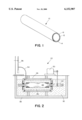
- FIG. 1 is a sectional perspective view of an embodiment of a composite gas-separation module of this invention.
- FIG. 2 is a view, partially schematic and partially in cross-section, of an apparatus for electroless plating a membrane on a support by the method of this invention.
- FIG. 1 illustrates one embodiment of a cylindrical hydrogen gas-extraction module 10 of the invention.
- Module 10 includes porous metal substrate 12, intermediate layer 14 and membrane 16 that is selectively permeable to hydrogen.
- the oxidized intermediate layer may be on the interior surface of the substrate, with the membrane forming the innermost of the three cylindrical layers.
- the module can take any of a variety of forms, such as a porous flat plate.
- substrate 12 has a thickness of 1.6 millimeters, or 1/16th of an inch, and a porosity in a range of 15 to 50% with pore sizes in a range of 0.2 to 0.5 micrometers. A smaller pore size is preferred, though the size of pores in substrate 12 in some embodiments is 1 or 2 micrometers or even as great as 5 micrometers or more.
- substrate 12 is formed of porous stainless steel. Cylinders of porous stainless steel that are suitable for use as substrates are available from Mott Metallurgical Corp. (Farmington, Conn.), for example.
- substrate 12 can be formed of any of a number of other porous materials, such as iron, nickel, titanium, chromium and aluminum, as well as alloys of any of these metals. Serving primarily as a support structure, substrate 12 enhances the durability and strength of the module.
- Oxidized intermediate layer 14 is a ceramic material formed when a metal of substrate 12 is oxidized in an oxidation-reduction reaction with, for example, oxygen, nitrogen or carbon.
- oxidize refers to the process of taking an electron away from a reducing agent in an oxidation-reduction reaction.
- concentration of the metal that is to be oxidized at the surface of the substrate must be substantial.
- the term, "substantial,” is used to designate a concentration that is sufficient to provide a diffusion-resistant coating across the surface of substrate 12 when oxidized.
- the metal that is oxidized is present in a substantial concentration throughout substrate 12, as is iron in steel, for example.
- the molar concentration of the metal that is to be oxidized is preferably more than half.
- other oxidizable metals are found in steel, most are present in very small or trace amounts, i.e., a few percent or less. These concentrations are generally considered insubstantial.
- the concentration of an easily-diffused element such as aluminum can be made "substantial” by heating substrate 12 to a temperature around 1000° C. to 1050° C. The temperature, however, should not be driven so high as to collapse the pores of the porous substrate. At this temperature, the aluminum diffuses to the surface of the steel substrate, creating a disproportionately high aluminum concentration at the surface despite the relatively low concentration of aluminum in the substrate as a whole. If, under these circumstances, the aluminum that has diffused to the surface can be oxidized to form a diffusion-resistant aluminum oxide coating, then the concentration of aluminum at the surface is "substantial.”
- a metal to be oxidized is deposited on the surface of a porous foundation to form substrate 12.
- the porous foundation is stainless steel.
- the metal is deposited by deep-coating a metal powder with binder on the porous foundation or by any conventional method.
- Metals suitable for deposition include tantalum, niobium, vanadium, aluminum, and other metals that can be easily oxidized in air.
- the deposited layer is then oxidized as in the other embodiments with the temperature controlled to provide an intermediate layer 14 of desired thickness. Note that tantalum, vanadium and niobium are extremely unstable in air and will rapidly oxidize in such an environment.
- the thickness of intermediate layer 14 can vary from a few micrometers to tens of micrometers.
- Intermediate layer 14 is coated by a membrane 16 that is selectively permeable to hydrogen.
- membrane 16 has a thickness of about 18 to 32 micrometers and is selectively permeable to at least one gas but not to others.
- a membrane 16 of palladium or certain of its alloys, for example, allows diffusion of hydrogen gas through the membrane while posing a nearly impermeable barrier to other gases. Therefore, membranes comprising palladium or its alloys are particularly desirable for selectively extracting hydrogen.
- membrane 16 is preferably formed of a palladium alloy, such as an alloy of 75 to 77% palladium and 23 to 25% silver.
- a palladium alloy is preferred at low temperatures because pure palladium undergoes a phase change in the presence of hydrogen around 250° C., and this phase change will lead to embrittlement of the membrane after repeated cycling.
- the palladium/silver alloy is formed by first depositing palladium onto substrate 12 by electroless deposition and then depositing silver, also by electroless deposition.
- An alloy membrane layer 16 is then formed by heating the silver and palladium layers to 300 to 1000° C. in an inert or hydrogen atmosphere.
- other metals suitable for selectively extracting hydrogen include nickel, platinum, vanadium, niobium, tantalum, metals in Groups III-V, etc.
- any contaminants are initially cleaned from substrate 12 by placing substrate 12 in an ultrasonic bath with alkaline solution.
- substrate 12 can be ultrasonically soaked for half an hour with the temperature of the bath at about 60° C. Cleaning can then be followed by rinsing, wherein substrate 12 is sequentially rinsed in tap water, deionized water and isopropanol.
- Substrate 12 is then oxidized at an elevated temperature in a furnace to form intermediate layer 14.
- intermediate layer 14 inhibits intermetallic diffusion between metallic substrate 12 and palladium membrane 16, thereby protecting the integrity of palladium membrane 16 and extending its effective life.
- substrate 12 can be oxidized in air or pure oxygen.
- the temperature at which substrate 12 is oxidized depends on the metal or the composition of the alloy of which substrate 12 is comprised.
- oxidation is confined primarily to the outer surface of substrate 12.
- confinement of oxidation is promoted by sealing the interior surface of substrate 12 or by passing an inert gas through the interior of substrate 12.
- oxidation is confined primarily to the inner surface of substrate 12.
- the rate and depth of oxidation depend on the composition of the alloy and temperature. Contamination of the atmosphere with water and carbon dioxide (CO 2 ) often increases oxidation (corrosion) of stainless steel at elevated temperatures.
- iron in stainless steel oxidizes at temperatures below 570° C. to form Fe 3 O 4 and Fe 2 O 3 . Above 570° C., the iron oxidizes to form FeO, Fe 3 O 4 and Fe 2 O 3 .
- the efficiency of oxidation decreases significantly.
- Steels with a high concentration of chromium exhibit negligible oxidation rates in air at temperatures up to 700° C.
- a stainless steel substrate is suitably oxidized by heating it to 900° C. in air or in an atmosphere of nitrogen or oxygen. Oxidation continues under these conditions for about 4 hours. Due to interaction between substrate 12 and the oxidizing gas, a substantially-uniform ceramic coating of, for example, iron oxide or iron nitride is formed, in situ, on the surface of substrate 12.
- a nitride intermediate layer is used.
- a suitable nitride intermediate layer can be formed on substrate 12 by oxidizing substrate 12 in an ammonia-bearing or nitrogen-based atmosphere.
- Substrate 12 is exposed to a gas mixture wherein ammonia (NH 3 ) is present in a concentration as low as just a few percent.
- the nitride layer forms at a temperature in the range of 500 to 1000° C.
- the required exposure time and the depth of the nitride layer depend on the composition of the substrate, temperature, ammonia concentration (if any), and composition of the nitride-forming gas.
- a carbide intermediate layer is formed on substrate 12 by oxidizing substrate 12 in an atmosphere including carbon monoxide (CO), methane (CH 4 ) or other hydrocarbon gases at elevated temperatures.
- the carbide-forming process is typically carried out at temperatures of 840 to 930° C.
- intermediate layer 14 can further include a coating of a second protective layer, such as a layer of alumina, silica, mullite, cordierite, zirconia, titania, tantalum oxide, tungsten or magnesium oxide, applied by a suitable method.
- a second protective layer such as a layer of alumina, silica, mullite, cordierite, zirconia, titania, tantalum oxide, tungsten or magnesium oxide, applied by a suitable method.
- intermediate layer 14 Following the formation of intermediate layer 14, the outer surface of intermediate layer 14 is activated.
- the purpose of surface activation is to seed intermediate layer 14 with nuclei of the metal that forms the membrane. In this embodiment, that metal is palladium.
- the membrane is subsequently applied to the intermediate layer 14 by electroless plating, the palladium nuclei on the surface of intermediate layer 14 initiate an autocatalytic process of reducing a metastable palladium salt complex on intermediate layer 14.
- Substrate 12 and intermediate layer 14 together form a tubular support 22 (shown in FIG. 2) for the membrane.
- support 22 is alternately immersed in SnCl 2 and PdCl 2 baths.
- Support 22 is first immersed for about five minutes in an acidic SnCl 2 bath to sensitize support 22. Then, support 22 is immersed for a period in a range of between about three and about five minutes in an acidic PdCl 2 bath to seed support 22 with palladium nuclei. The temperature of each bath is 20° C. After each immersion in the SnCl 2 bath, support 22 is gently rinsed with deionized water. After each immersion in the PdCl 2 bath, support 22 is rinsed first with 0.01 molar hydrochloric acid (HCl) and then with water. The 0.01 M HCl is used to prevent hydrolysis of Pd 2+ ions.
- HCl 0.01 molar hydrochloric acid
- Sn 2+ ions on the surface of support 22 are partially hydrolyzed to form a relatively-insoluble product (Sn(OH) 1 .5 Cl 0 .5 and other more complicated hydroxyl-chlorides).
- the products of hydrolysis are strongly attached to the surface as a layer having a thickness on the order of a few angstroms.
- the composition, structure, and thickness of this layer depend on factors such as the ratio of HCl to SnCl 2 , the structure, roughness and shape of the support surface, and the hydrodynamic regime of rinsing.
- the two-step immersion sequence in SnCl 2 and PdCl 2 solutions is repeated between about two and about ten times, preferably between about two and five times, depending on the intensity of the activation.
- the activated layer has a uniform dark-brown color and smooth surface.
- the activation layer has a structure comprising a number of thin layers, each formed after a sensitizing/activation cycle, of palladium nuclei. These preseeded palladium nuclei reduce the induction period of the autocatalytic process at the start of the electroless plating of palladium.
- the palladium membrane can be deposited without the surface activation procedure described above. Absent activation, however, the nucleation process is very slow and the induction period is extended. As a result, plating is slow. In either case, the growth rate of the palladium membrane accelerates due to autocatalytic deposition after the content of the deposited palladium reaches about 0.1 mg/cm 2 .
- Apparatus 20, illustrated in FIG. 2 is used for electroless plating of palladium.
- the composition of solution 28 used for electroless plating is preferably as follows:
- this bath is maintained at a temperature of about 60° C.
- the bath typically has a pH of approximately 10.4 and is provided in a quantity sufficient to provide approximately 3.5 cm 3 of solution per square centimeter of plating area.
- Activated tubular support 22 comprising the activated intermediate layer 14 coated on a porous metal substrate 12, is mounted on nonporous stainless steel tube 24 in plating cell 26.
- Plating cell 26 is filled with electroless plating solution 28.
- Controlled axial rotation of tube 24 by motor 30 promotes uniform deposition of palladium upon support 22.
- Temperature control of the bath is provided by immersing plating cell 26 in water jacket 32 within surrounding vessel 38.
- gaseous reaction products evolve.
- the main component of the gaseous products is nitrogen.
- the plating activity decreases with the depletion of palladium ions and hydrazine (H 2 NNH 2 ) and the decrease in the pH of plating solution 28.
- a new solution is provided, and the procedure is repeated.
- a stable high rate of deposition for each plating is achieved not only by changing plating solution 28, but also by carefully rinsing the membrane between platings. Typically, the membrane is rinsed a minimum of five times with deionized water at 50 to 60° C. for 2 to 5 minutes.
- palladium can be deposited on support 22 by other suitable techniques, such as electroplating, spray deposition, vacuum sputtering, etc.
- the thus-formed palladium membrane covers the intermediate layer and seals the pores at the surface of support 22.
- An increase in the flux of hydrogen through the module also can be achieved by decreasing the thickness of the palladium layer and increasing the porosity of support 22. To deposit a thinner layer of palladium, the pore size of support 22 is smaller or is decreased prior to palladium deposition.
- the palladium membrane When the completed module is surrounded with a hydrogen-containing atmosphere, the palladium membrane causes the hydrogen gas to dissociate and dissolve through the membrane as an element. As a result, hydrogen is selectively removed from the surrounding atmosphere into the volume within the cylinder.
- a pressure gradient wherein pressure within the cylinder is less than that surrounding the cylinder, can be maintained to increase the flux of hydrogen through the module.
- the reaction products include hydrogen gas.
- Reactants at least one of which includes molecularly-bound hydrogen, are placed between or within modules of this invention.
- hydrogen gas is removed by the module from the volume wherein the reactants react.
- the reaction is equilibrium controlled. Accordingly, the reaction is limited by the accumulation of hydrogen gas, wherein the reaction reaches equilibrium when a sufficient quantity of hydrogen has accumulated.
- hydrogen is separated from the reactants, however, the reaction is driven to completion.
- methane/steam reformation methane and steam are passed through or around a tubular module of this invention in the presence of a catalyst. The methane and steam react to produce carbon monoxide and hydrogen, and the hydrogen is dissociated into the membrane and thereby separated from the other gases.
- An asymmetric composite palladium/porous stainless steel module was prepared as follows.
- a porous 316L stainless steel cup was electrically welded to a non-porous stainless steel tube.
- the cup had an outside diameter of 12.7 mm or 1/2 inch, a wall thickness of 1.6 mm or 1/16 inch, and a length of 25 mm or 1 inch.
- Contaminants were removed by cleaning the cup in an ultrasonic bath with alkaline solution at 60° C. for a half hour. This cleaning procedure was followed by sequentially rinsing the cup in tap water, deionized water and isopropanol.
- the cup was then oxidized with oxygen at 900° C. for 4 hours.
- the rate of heating and cooling was 3° C./min.
- the oxidized cup was surface activated by immersing the cup in baths of SnCl 2 and PdCl 2 , as described previously in this specification. The immersion treatments were repeated 5 times, and the activated cup was then dried for 2 hours at 120° C.
- the plating solution had the following composition: 4 g/l Pd(NH 3 ) 4 Cl 2 .H 2 O, 198 ml/l NH 4 OH (28%), 40.1 g/l Na 2 EDTA, and 6 ml/l H 2 NNH 2 (1 M).
- the plating solution and cup were then placed in a water bath at 60° C. This plating procedure was repeated 14 times. The total time of plating was 25 hours, and the thickness of the palladium layer was 32.5 ⁇ m.
- Hydrogen permeation measurements of the prepared module were carried out in a chamber wherein a controlled flow of pure hydrogen gas served as a feed gas.
- the feed gas flowed through the chamber and across the surface of the oxidized cup.
- Hydrogen gas was selectively extracted from the surrounding gas through the cup and into the stainless steel tube welded to the cup.
- the permeant hydrogen gas was then measured as a volumetric flow rate as it flowed through the tube.
- Example 1 The procedure as in Example 1 was carried out with the following exceptions. Oxidation of the cup was performed at 600° C. for 4 hours. The palladium deposition procedure was repeated 12 times. The total time of plating was 18 hours. Finally, the thickness of the palladium layer was 25.4 ⁇ m.
- Example 1 The procedure as in Example 1 was carried out with the following exceptions. Oxidation of the cup was performed at 800° C. for 4 hours. The palladium deposition procedure was repeated 16 times. The total time of plating was 24 hours. Finally, the thickness of the palladium layer was 30.2 ⁇ m.
- Example 1 The procedure as in Example 1 was carried out with the following exceptions.
- the cup was oxidized with nitrogen rather than oxygen.
- the nitriding of the cup was performed at 980° C. for 20 hours in an equal mixture of nitrogen and hydrogen.
- the palladium deposition procedure was repeated 12 times.
- the total time of plating was 20 hours.
- the thickness of the palladium layer was 26.1 ⁇ m.
- Example 1 The procedure as in Example 1 was carried out with the following exceptions. No preliminary treatment of the cup was performed except gentle brushing of the porous stainless steel. The cup was not oxidized. The palladium deposition procedure was repeated 9 times. The total time of plating was 14 hours. Finally, the thickness of the palladium layer was 18.6 ⁇ m.
- the oxidized cups (1-4) demonstrated, over time, a permeability to hydrogen significantly greater than that of the nonoxidized cup (5). Furthermore, all cups having an intermediate layer, formed by in-situ oxidation demonstrated long-term stability at 350° C.
- the cup described in Example 1 showed little decline in its hydrogen flux rate after more than 4,000 hours.
- the oxidized cups showed an increase in hydrogen flux of about 20% during the first 100 hours. The basis for this increase is unclear. However, it is suspected that the increase is due to a rearrangement of the microstructure of the intermediate layer. In contrast, the membrane prepared without such a layer showed a 25% decrease in hydrogen flux during the first 100 hours.
Abstract
Description
2Pd(NH.sub.3).sub.4 Cl.sub.2 +H.sub.2 NNH.sub.2 +4NH.sub.4 OH→2Pd+N.sub.2 +8NH.sub.3 +4NH.sub.4 Cl+4H.sub.2 O
2Pd.sup.2+ +H.sub.2 NNH.sub.2 +4OH.sup.- →2Pd+N.sub.2 +4H.sub.2 O
______________________________________
Pd(NH.sub.3).sub.4 Cl.sub.2.H.sub.2 O, g/l
                  4.0
NH.sub.4 OH(28%), ml/l
                  198
Na.sub.2 EDTA, g/l
                  40.1
H.sub.2 NNH.sub.2 (1 M), ml/l
                  5.6-7.6
______________________________________
______________________________________
Duration of
the
exposure at
        Hydrogen permeability, m.sup.3 · μm/(m.sup.2
        · h · atm.sup.0.5)
350° C.
        Example 1
                 Example 2
                          Example 3
                                 Example 4
                                        Example 5
______________________________________
  1 h   160.2    194.2    120.2  151.7  73.4
 100 h  209.7    228.7    148.8  179.1  54.8
 500 h  208.1    --       --     --     38.0
1000 h  208.6    --       --     --     --
4000 h  172.5    --       --     --     --
______________________________________
Claims (30)
Priority Applications (8)
| Application Number | Priority Date | Filing Date | Title |
|---|---|---|---|
| US09/139,218 US6152987A (en) | 1997-12-15 | 1998-08-24 | Hydrogen gas-extraction module and method of fabrication |
| CA002315029A CA2315029C (en) | 1997-12-15 | 1998-12-11 | Hydrogen gas-extraction module |
| DE69812416T DE69812416T2 (en) | 1997-12-15 | 1998-12-11 | EXTRACTION MODULE FOR GASEOUS HYDROGEN |
| ES98962089T ES2195429T3 (en) | 1997-12-15 | 1998-12-11 | HYDROGEN GAS EXTRACTION MODULE. |
| EP98962089A EP1042049B1 (en) | 1997-12-15 | 1998-12-11 | Hydrogen gas-extraction module |
| AT98962089T ATE234661T1 (en) | 1997-12-15 | 1998-12-11 | EXTRACTION MODULE FOR GASFORM HYDROGEN |
| AU17251/99A AU1725199A (en) | 1997-12-15 | 1998-12-11 | Hydrogen gas-extraction module |
| PCT/US1998/026466 WO1999030806A1 (en) | 1997-12-15 | 1998-12-11 | Hydrogen gas-extraction module |
Applications Claiming Priority (2)
| Application Number | Priority Date | Filing Date | Title |
|---|---|---|---|
| US99101797A | 1997-12-15 | 1997-12-15 | |
| US09/139,218 US6152987A (en) | 1997-12-15 | 1998-08-24 | Hydrogen gas-extraction module and method of fabrication |
Related Parent Applications (1)
| Application Number | Title | Priority Date | Filing Date |
|---|---|---|---|
| US99101797A Continuation-In-Part | 1997-12-15 | 1997-12-15 |
Publications (1)
| Publication Number | Publication Date |
|---|---|
| US6152987A true US6152987A (en) | 2000-11-28 |
Family
ID=26836991
Family Applications (1)
| Application Number | Title | Priority Date | Filing Date |
|---|---|---|---|
| US09/139,218 Expired - Lifetime US6152987A (en) | 1997-12-15 | 1998-08-24 | Hydrogen gas-extraction module and method of fabrication |
Country Status (8)
| Country | Link |
|---|---|
| US (1) | US6152987A (en) |
| EP (1) | EP1042049B1 (en) |
| AT (1) | ATE234661T1 (en) |
| AU (1) | AU1725199A (en) |
| CA (1) | CA2315029C (en) |
| DE (1) | DE69812416T2 (en) |
| ES (1) | ES2195429T3 (en) |
| WO (1) | WO1999030806A1 (en) |
Cited By (107)
| Publication number | Priority date | Publication date | Assignee | Title |
|---|---|---|---|---|
| US6315820B1 (en) * | 1999-10-19 | 2001-11-13 | Ford Global Technologies, Inc. | Method of manufacturing thin metal alloy foils |
| US20020141920A1 (en) * | 2001-03-30 | 2002-10-03 | Alvin Mary Anne | Metal gas separation membrane module design |
| US6475268B2 (en) * | 2000-12-22 | 2002-11-05 | Ford Global Technologies, Inc. | Supported membrane for hydrogen separation |
| US6572683B2 (en) * | 2000-11-24 | 2003-06-03 | Sumitomo Electric Industries, Ltd. | Substance separation structure and method of preparing the same |
| US6581684B2 (en) | 2000-04-24 | 2003-06-24 | Shell Oil Company | In Situ thermal processing of a hydrocarbon containing formation to produce sulfur containing formation fluids |
| US6588504B2 (en) | 2000-04-24 | 2003-07-08 | Shell Oil Company | In situ thermal processing of a coal formation to produce nitrogen and/or sulfur containing formation fluids |
| US20030183080A1 (en) * | 2002-03-05 | 2003-10-02 | Mundschau Michael V. | Hydrogen transport membranes |
| US20030190486A1 (en) * | 2002-04-03 | 2003-10-09 | Fernando Roa | Process for Preparing Palladium Alloy Composite Membranes for Use in Hydrogen Separation, Palladium Alloy Composite Membranes and Products Incorporating or Made from the Membranes |
| US6649559B2 (en) * | 2000-08-12 | 2003-11-18 | Dmc2 Degussa Metals Catalysts Cerdec Ag | Supported metal membrane, a process for its preparation and use |
| WO2003101629A1 (en) | 2002-05-29 | 2003-12-11 | The Board Of Trustees Of The Leland Stanford Junior University | Sub-micron electrolyte thin film on nano-porous substrate by oxidation of metal film |
| US6698515B2 (en) | 2000-04-24 | 2004-03-02 | Shell Oil Company | In situ thermal processing of a coal formation using a relatively slow heating rate |
| US6715548B2 (en) | 2000-04-24 | 2004-04-06 | Shell Oil Company | In situ thermal processing of a hydrocarbon containing formation to produce nitrogen containing formation fluids |
| US6715546B2 (en) | 2000-04-24 | 2004-04-06 | Shell Oil Company | In situ production of synthesis gas from a hydrocarbon containing formation through a heat source wellbore |
| US20040129135A1 (en) * | 2002-03-05 | 2004-07-08 | Roark Shane E. | Dense, layered membranes for hydrogen separation |
| US20040197593A1 (en) * | 2003-04-04 | 2004-10-07 | Anand Chellappa | Surface modification of porous metal substrates using cold spray |
| US20040194626A1 (en) * | 2003-04-04 | 2004-10-07 | Anand Chellappa | Surface modification of porous metal substrates |
| WO2004085034A2 (en) * | 2003-03-21 | 2004-10-07 | Worcester Polytechnic Institute | Composite gas separations modules having intermediate metal layers |
| WO2004098751A1 (en) * | 2003-05-02 | 2004-11-18 | Worcester Polytechnic Institute | Composite gas separation modules having high tamman temperature intermediate layers |
| US20040237780A1 (en) * | 2003-03-21 | 2004-12-02 | Worcester Polytechnic Institute | Method for fabricating composite gas separation modules |
| US20040244583A1 (en) * | 2003-03-21 | 2004-12-09 | Worcester Polytechnic Institute | Method for curing defects in the fabrication of a composite gas separation module |
| US20040244589A1 (en) * | 2003-06-04 | 2004-12-09 | Bossard Peter R. | Composite structure for high efficiency hydrogen separation and its associated methods of manufacture and use |
| US20050011359A1 (en) * | 2001-07-25 | 2005-01-20 | Xiulian Pan | Metal solution-diffusion membrane and method for producing the same |
| US20050045034A1 (en) * | 2003-08-29 | 2005-03-03 | The Regents Of The University Of California | Tubular hydrogen permeable metal foil membrane and method of fabrication |
| WO2005026043A2 (en) * | 2003-07-29 | 2005-03-24 | Intelligent Energy, Inc. | Methods for providing thin hydrogen separation membranes and associated uses |
| US20050061145A1 (en) * | 2003-09-24 | 2005-03-24 | Siemens Westinghouse Power Corporation | Metal gas separation membrane |
| US20050072304A1 (en) * | 2001-02-19 | 2005-04-07 | Claude Etievant | Composite structures of membranes that are selectively permeable to hydrogen and combustible gas processors using same |
| US20050113316A1 (en) * | 2001-07-24 | 2005-05-26 | Panagin Pharmaceuticals Inc. | Process for producing dammarane sapogenins and ginsenosides |
| US20050109609A1 (en) * | 2003-11-25 | 2005-05-26 | Min-Hon Rei | Method for forming supported palladium membrane used for hydrogen purification |
| EP1547673A1 (en) * | 2003-12-19 | 2005-06-29 | Min-Hon Rei | Method for forming supported palladium membrane used for hydrogen purification |
| WO2005075060A1 (en) * | 2004-02-02 | 2005-08-18 | Bossard Peter R | Composite structure for high efficiency hydrogen separation and its associated methods of manufacture and use |
| US20050241477A1 (en) * | 2002-03-05 | 2005-11-03 | Mundschau Michael V | Hydrogen transport membranes |
| US20060016332A1 (en) * | 2004-07-21 | 2006-01-26 | Ma Yi H | Composite gas separation modules having a layer of particles with a uniform binder metal distribution |
| US20060248800A1 (en) * | 2002-09-05 | 2006-11-09 | Miglin Maria T | Apparatus and process for production of high purity hydrogen |
| US20060260466A1 (en) * | 2005-05-23 | 2006-11-23 | Kabushiki Kaisha Kobe Seiko Sho (Kobe Steel, Ltd.) | Hydrogen permeable member and method for production thereof |
| US7201782B2 (en) | 2002-09-16 | 2007-04-10 | Hewlett-Packard Development Company, L.P. | Gas generation system |
| WO2007024253A3 (en) * | 2005-12-23 | 2007-06-28 | United Technologies Corp | Composite palladium membrane having long-term stability for hydrogen separation |
| EP1849510A1 (en) | 2006-04-26 | 2007-10-31 | Acktar Ltd. | Composite inorganic membrane for separation in fluid systems |
| US20080000350A1 (en) * | 2006-02-06 | 2008-01-03 | Eltron Research Inc. | Hydrogen separation process |
| US20080019902A1 (en) * | 2004-01-21 | 2008-01-24 | Green Hydrotec Inc. | Process for producing hydrogen |
| US20080038567A1 (en) * | 2002-04-03 | 2008-02-14 | Way J D | Sulfur-Resistant composite Metal Membranes |
| US7341609B2 (en) | 2002-10-03 | 2008-03-11 | Genesis Fueltech, Inc. | Reforming and hydrogen purification system |
| WO2008041968A2 (en) * | 2006-09-28 | 2008-04-10 | Utc Power Corporation | Pd membrane having improved h2-permeance, and method of making |
| US20080230681A1 (en) * | 2007-03-23 | 2008-09-25 | Fujitsu Limited | Image capture device |
| EP1983076A2 (en) | 2007-04-13 | 2008-10-22 | Green Hydrotec Inc. | Palladium-containing plating solution and its uses |
| WO2008156524A1 (en) * | 2007-06-14 | 2008-12-24 | Exxonmobil Upstream Research Company | Process for purification of hydrocarbons |
| US7527661B2 (en) | 2005-04-18 | 2009-05-05 | Intelligent Energy, Inc. | Compact devices for generating pure hydrogen |
| US20090120287A1 (en) * | 2007-02-20 | 2009-05-14 | Alan Anthony Del Paggio | Gas separation membrane system and a method of preparing or reconditioning and the use thereof |
| US20090176012A1 (en) * | 2007-08-22 | 2009-07-09 | Way J Douglas | Unsupported Palladium Alloy Membranes and Methods of Making Same |
| US7611565B1 (en) * | 2005-10-20 | 2009-11-03 | Los Alamos National Security, Llc | Device for hydrogen separation and method |
| US20090277331A1 (en) * | 2008-05-09 | 2009-11-12 | Membrane Reactor Technologies Ltd. | Hydrogen separation composite membrane module and the method of production thereof |
| US20090286890A1 (en) * | 2008-05-15 | 2009-11-19 | Mahendra Ladharam Joshi | Method for recovering a natural gas contaminated with high levels of co2 |
| US7644765B2 (en) | 2006-10-20 | 2010-01-12 | Shell Oil Company | Heating tar sands formations while controlling pressure |
| US7673786B2 (en) | 2006-04-21 | 2010-03-09 | Shell Oil Company | Welding shield for coupling heaters |
| US20100132546A1 (en) * | 2007-04-05 | 2010-06-03 | Yi Hua Ma | Composite Structures with Porous Anodic Oxide Layers and Methods of Fabrication |
| US7735935B2 (en) | 2001-04-24 | 2010-06-15 | Shell Oil Company | In situ thermal processing of an oil shale formation containing carbonate minerals |
| US7749305B1 (en) | 2003-06-04 | 2010-07-06 | Bossard Peter R | Composite structure for high efficiency hydrogen separation containing preformed nano-particles in a bonded layer |
| US7789941B2 (en) * | 1996-10-30 | 2010-09-07 | Idatech, Llc | Hydrogen purification membranes, components and fuel processing systems containing the same |
| US7798220B2 (en) | 2007-04-20 | 2010-09-21 | Shell Oil Company | In situ heat treatment of a tar sands formation after drive process treatment |
| US7831134B2 (en) | 2005-04-22 | 2010-11-09 | Shell Oil Company | Grouped exposed metal heaters |
| US20100285399A1 (en) * | 2009-05-08 | 2010-11-11 | Taiwan Semiconductor Manufacturing Co., Ltd. | Wafer edge exposure unit |
| US7866386B2 (en) | 2007-10-19 | 2011-01-11 | Shell Oil Company | In situ oxidation of subsurface formations |
| US7867300B2 (en) | 2001-03-02 | 2011-01-11 | Intelligent Energy, Inc. | Ammonia-based hydrogen generation apparatus and method for using same |
| US7875089B2 (en) | 2001-03-02 | 2011-01-25 | Intelligent Energy, Inc. | Ammonia-based hydrogen generation apparatus and method for using same |
| CN101983757A (en) * | 2010-12-06 | 2011-03-09 | 西北有色金属研究院 | Palladium composite membrane taking multihole FeAlCr as substrate and preparation method thereof |
| US7922781B2 (en) | 2001-03-02 | 2011-04-12 | Chellappa Anand S | Hydrogen generation apparatus and method for using same |
| US20110104577A1 (en) * | 2009-06-16 | 2011-05-05 | Jingyu Cui | Systems and processes for operating fuel cell systems |
| US20110111315A1 (en) * | 2009-06-16 | 2011-05-12 | Jingyu Cui | Systems and processes of operating fuel cell systems |
| US20110111314A1 (en) * | 2009-06-16 | 2011-05-12 | Jingyu Cui | Systems and processes for operating fuel cell systems |
| US7942203B2 (en) | 2003-04-24 | 2011-05-17 | Shell Oil Company | Thermal processes for subsurface formations |
| US20110200493A1 (en) * | 2008-01-16 | 2011-08-18 | Jingyu Cui | system and process for making hydrogen from a hydrocarbon stream |
| US8002875B1 (en) | 2004-02-02 | 2011-08-23 | Bossard Peter R | System and method for separating hydrogen gas from a mixed gas source using composite structure tubes |
| US8151880B2 (en) | 2005-10-24 | 2012-04-10 | Shell Oil Company | Methods of making transportation fuel |
| US8151907B2 (en) | 2008-04-18 | 2012-04-10 | Shell Oil Company | Dual motor systems and non-rotating sensors for use in developing wellbores in subsurface formations |
| US8172913B2 (en) | 2002-04-23 | 2012-05-08 | Vencill Thomas R | Array of planar membrane modules for producing hydrogen |
| US8224163B2 (en) | 2002-10-24 | 2012-07-17 | Shell Oil Company | Variable frequency temperature limited heaters |
| US8220539B2 (en) | 2008-10-13 | 2012-07-17 | Shell Oil Company | Controlling hydrogen pressure in self-regulating nuclear reactors used to treat a subsurface formation |
| WO2012112046A1 (en) | 2011-02-18 | 2012-08-23 | Stichting Energieonderzoek Centrum Nederland | Membrane reactor and process for the production of a gaseous product with such reactor |
| US8327932B2 (en) | 2009-04-10 | 2012-12-11 | Shell Oil Company | Recovering energy from a subsurface formation |
| US8355623B2 (en) | 2004-04-23 | 2013-01-15 | Shell Oil Company | Temperature limited heaters with high power factors |
| US20130152784A1 (en) * | 2011-12-20 | 2013-06-20 | Shell Oil Company | Method of making a composite gas separation module |
| US20130152785A1 (en) * | 2011-12-20 | 2013-06-20 | Shell Oil Company | Method of preparing a palladium-silver alloy gas separation membrane system |
| US20130152786A1 (en) * | 2010-08-30 | 2013-06-20 | Stichting Energieonderzoek Centrum Nederland | Seeding method for deposit of thin selective membrane layers |
| US20130156949A1 (en) * | 2011-12-16 | 2013-06-20 | Industrial Technology Research Institute | Methods of fabricating porous media and inorganic selective membrane |
| US8518151B2 (en) | 2010-03-24 | 2013-08-27 | L'Air Liquide Societe Anonyme pour l'Etude el l'Exploitation des Procedes Georges Claude | Porous hollow fiber supported dense membrane for hydrogen production, separation, or purification |
| US8627887B2 (en) | 2001-10-24 | 2014-01-14 | Shell Oil Company | In situ recovery from a hydrocarbon containing formation |
| US8631866B2 (en) | 2010-04-09 | 2014-01-21 | Shell Oil Company | Leak detection in circulated fluid systems for heating subsurface formations |
| US8652239B2 (en) | 2010-05-03 | 2014-02-18 | Worcester Polytechnic Institute | High permeance sulfur tolerant Pd/Cu alloy membranes |
| US8701769B2 (en) | 2010-04-09 | 2014-04-22 | Shell Oil Company | Methods for treating hydrocarbon formations based on geology |
| JP2014097443A (en) * | 2012-11-13 | 2014-05-29 | Tomyeng Corp | Hydrogen separation membrane, hydrogen separator, and organic hydride system |
| US8778058B2 (en) | 2010-07-16 | 2014-07-15 | Colorado School Of Mines | Multilayer sulfur-resistant composite metal membranes and methods of making and repairing the same |
| US8820406B2 (en) | 2010-04-09 | 2014-09-02 | Shell Oil Company | Electrodes for electrical current flow heating of subsurface formations with conductive material in wellbore |
| US8900344B2 (en) | 2010-03-22 | 2014-12-02 | T3 Scientific Llc | Hydrogen selective protective coating, coated article and method |
| WO2015020503A1 (en) * | 2013-08-09 | 2015-02-12 | Samsung Electronics Co., Ltd. | Separation membrane, hydrogen separation membrane including separation membrane, and device including hydrogen separation membrane |
| US20150068451A1 (en) * | 2010-03-26 | 2015-03-12 | Shell Oil Company | Supported gas separation membrane and method |
| US9016370B2 (en) | 2011-04-08 | 2015-04-28 | Shell Oil Company | Partial solution mining of hydrocarbon containing layers prior to in situ heat treatment |
| US9033042B2 (en) | 2010-04-09 | 2015-05-19 | Shell Oil Company | Forming bitumen barriers in subsurface hydrocarbon formations |
| US20150328589A1 (en) * | 2012-12-14 | 2015-11-19 | Korea Institute Of Energy Research | Hydrogen separation membrane module for capturing carbon dioxide |
| US9309755B2 (en) | 2011-10-07 | 2016-04-12 | Shell Oil Company | Thermal expansion accommodation for circulated fluid systems used to heat subsurface formations |
| US20160288114A1 (en) * | 2015-03-31 | 2016-10-06 | James Douglas Way | Ammonia Synthesis at Moderate Conditions Using Hydrogen Permeable Membrane Reactors |
| US9605524B2 (en) | 2012-01-23 | 2017-03-28 | Genie Ip B.V. | Heater pattern for in situ thermal processing of a subsurface hydrocarbon containing formation |
| US9732422B2 (en) | 2015-01-23 | 2017-08-15 | United Technologies Corporation | Method of coating metallic powder particles |
| AT15581U1 (en) * | 2016-12-09 | 2018-03-15 | Plansee Se | membrane tube |
| JP2018510058A (en) * | 2015-03-18 | 2018-04-12 | シエル・インターナシヨナル・リサーチ・マートスハツペイ・ベー・ヴエー | Method for producing gas separation membrane with gold on palladium |
| WO2018078494A1 (en) | 2016-10-25 | 2018-05-03 | Nova Chemicals (International) S.A. | Use of semipermeable membranes in cracking coils |
| US10047594B2 (en) | 2012-01-23 | 2018-08-14 | Genie Ip B.V. | Heater pattern for in situ thermal processing of a subsurface hydrocarbon containing formation |
| JP2020525270A (en) * | 2017-06-30 | 2020-08-27 | コモンウェルス サイエンティフィック アンド インダストリアル リサーチ オーガナイゼーション | A method of joining and sealing a vanadium-based film to a metal joint |
| GB2602332A (en) * | 2020-12-23 | 2022-06-29 | Hydrogen Mem Tech As | Membrane attachment technique |
Families Citing this family (18)
| Publication number | Priority date | Publication date | Assignee | Title |
|---|---|---|---|---|
| US6547858B1 (en) | 1999-03-22 | 2003-04-15 | Idatech, Llc | Hydrogen-permeable metal membrane and hydrogen purification assemblies containing the same |
| US6319306B1 (en) | 2000-03-23 | 2001-11-20 | Idatech, Llc | Hydrogen-selective metal membrane modules and method of forming the same |
| US6221117B1 (en) | 1996-10-30 | 2001-04-24 | Idatech, Llc | Hydrogen producing fuel processing system |
| US6152995A (en) * | 1999-03-22 | 2000-11-28 | Idatech Llc | Hydrogen-permeable metal membrane and method for producing the same |
| US6602325B1 (en) | 1999-10-21 | 2003-08-05 | Ati Properties, Inc. | Fluid separation assembly |
| DE19983751B4 (en) * | 1998-11-10 | 2008-04-17 | ATI Properties, Inc., Gardena | Hydrogen Segregation membrane |
| DE19936548B4 (en) * | 1999-08-03 | 2004-03-04 | Alstom Power Energy Recovery Gmbh | Process and plant for the thermal cracking of hydrocarbons, in particular for the production of olefins |
| US7297183B2 (en) | 2004-09-20 | 2007-11-20 | Idatech, Llc | Hydrogen purification devices, components, and fuel processing systems containing the same |
| EP1789172A1 (en) * | 2004-09-21 | 2007-05-30 | Worcester Polytechnic Institute | Membrane enhanced reactor |
| WO2006034100A1 (en) * | 2004-09-21 | 2006-03-30 | Worcester Polytechnic Institute | Membrane steam reformer |
| EP1791631A1 (en) * | 2004-09-21 | 2007-06-06 | Worcester Polytechnic Institute | Reactor and process for steam reforming |
| RU2305587C2 (en) * | 2004-10-25 | 2007-09-10 | Общество с ограниченной ответственностью "Объединенный центр исследований и разработок" (ООО "ЮРД-Центр") | Composite oxygen-conducting diaphragm |
| CN101616865B (en) | 2006-11-30 | 2012-11-07 | 国际壳牌研究有限公司 | Systems and processes for producing hydrogen and carbon dioxide |
| EP2228120A1 (en) | 2009-03-09 | 2010-09-15 | Shell Internationale Research Maatschappij B.V. | Operation of more than one furnace |
| WO2011026943A1 (en) | 2009-09-04 | 2011-03-10 | Shell Internationale Research Maatschappij B.V. | Process to prepare a diluted hydrogen gas mixture |
| US10476093B2 (en) | 2016-04-15 | 2019-11-12 | Chung-Hsin Electric & Machinery Mfg. Corp. | Membrane modules for hydrogen separation and fuel processors and fuel cell systems including the same |
| NL2026450B1 (en) | 2019-09-11 | 2022-02-21 | Cramwinckel Michiel | Process to convert a waste polymer product to a gaseous product |
| US11712655B2 (en) | 2020-11-30 | 2023-08-01 | H2 Powertech, Llc | Membrane-based hydrogen purifiers |
Citations (20)
| Publication number | Priority date | Publication date | Assignee | Title |
|---|---|---|---|---|
| US2958391A (en) * | 1958-02-24 | 1960-11-01 | Universal Oil Prod Co | Purification of hydrogen utilizing hydrogen-permeable membranes |
| US3241298A (en) * | 1962-11-26 | 1966-03-22 | Union Carbide Corp | Method for making a fine porosity filter element |
| US3413777A (en) * | 1965-06-22 | 1968-12-03 | Engelhard Min & Chem | Hydrogen diffusion and method for producing same |
| US3428476A (en) * | 1965-06-22 | 1969-02-18 | Engelhard Min & Chem | Method for producing hydrogen diffusion cells |
| US4496373A (en) * | 1981-12-11 | 1985-01-29 | Kernforschungsanlage Julich Gesellschaft Mit Beschrankter Haftung | Diffusion membrane and process for separating hydrogen from gas mixture |
| US4589891A (en) * | 1983-09-08 | 1986-05-20 | Kernforschungsanlage Julich Gesellschaft Mit Beschrankter Haftung | Hydrogen permeatin membrane, process for its manufacture and use |
| US4655797A (en) * | 1983-09-08 | 1987-04-07 | Kernforschungsanlage Julich Gesellschaft Mit Beschrankter Haftung | Fine screen and fine screen stack, their use and process for the manufacture of fine screens |
| US4902307A (en) * | 1988-11-18 | 1990-02-20 | California Institute Of Technology | Synthesis of SiO2 membrane on porous support and method of use of same |
| US5049167A (en) * | 1989-12-13 | 1991-09-17 | Membrane Technology & Research, Inc. | Multilayer interfacial composite membrane |
| US5139541A (en) * | 1990-08-10 | 1992-08-18 | Bend Research, Inc. | Hydrogen-permeable composite metal membrane |
| JPH04326931A (en) * | 1991-04-25 | 1992-11-16 | Mitsubishi Kakoki Kaisha Ltd | Production of hydrogen separation membrane |
| US5205841A (en) * | 1992-04-03 | 1993-04-27 | Tpc Technologies, Inc. | Apparatus and method for extracting hydrogen |
| US5217506A (en) * | 1990-08-10 | 1993-06-08 | Bend Research, Inc. | Hydrogen-permeable composite metal membrane and uses thereof |
| US5258339A (en) * | 1992-03-12 | 1993-11-02 | Worcester Polytechnic Institute | Formation of zeolite membranes from sols |
| US5259870A (en) * | 1990-08-10 | 1993-11-09 | Bend Research, Inc. | Hydrogen-permeable composite metal membrane |
| US5393325A (en) * | 1990-08-10 | 1995-02-28 | Bend Research, Inc. | Composite hydrogen separation metal membrane |
| US5449848A (en) * | 1989-06-13 | 1995-09-12 | Agency Of Industrial Science And Technology | Dehydrogenation process |
| US5498278A (en) * | 1990-08-10 | 1996-03-12 | Bend Research, Inc. | Composite hydrogen separation element and module |
| US5614001A (en) * | 1994-05-23 | 1997-03-25 | Ngk Insulators, Ltd. | Hydrogen separator, hydrogen separating apparatus and method for manufacturing hydrogen separator |
| US5738708A (en) * | 1995-06-07 | 1998-04-14 | The Regents Of The University Of California Office Of Technology Transfer | Composite metal membrane |
Family Cites Families (3)
| Publication number | Priority date | Publication date | Assignee | Title |
|---|---|---|---|---|
| SU1058587A1 (en) * | 1982-07-12 | 1983-12-07 | Всесоюзный Ордена Трудового Красного Знамени Научно-Исследовательский Проектно-Конструкторский И Технологический Институт Источников Тока | Method of producing membrane elements |
| JPS61138516A (en) * | 1984-12-10 | 1986-06-26 | Matsushita Electric Ind Co Ltd | Permselective compound membrane for gas |
| JP2960998B2 (en) * | 1991-09-25 | 1999-10-12 | 三菱重工業株式会社 | Hydrogen gas separation membrane |
-
1998
- 1998-08-24 US US09/139,218 patent/US6152987A/en not_active Expired - Lifetime
- 1998-12-11 ES ES98962089T patent/ES2195429T3/en not_active Expired - Lifetime
- 1998-12-11 DE DE69812416T patent/DE69812416T2/en not_active Expired - Lifetime
- 1998-12-11 EP EP98962089A patent/EP1042049B1/en not_active Expired - Lifetime
- 1998-12-11 WO PCT/US1998/026466 patent/WO1999030806A1/en active IP Right Grant
- 1998-12-11 AU AU17251/99A patent/AU1725199A/en not_active Abandoned
- 1998-12-11 CA CA002315029A patent/CA2315029C/en not_active Expired - Fee Related
- 1998-12-11 AT AT98962089T patent/ATE234661T1/en not_active IP Right Cessation
Patent Citations (20)
| Publication number | Priority date | Publication date | Assignee | Title |
|---|---|---|---|---|
| US2958391A (en) * | 1958-02-24 | 1960-11-01 | Universal Oil Prod Co | Purification of hydrogen utilizing hydrogen-permeable membranes |
| US3241298A (en) * | 1962-11-26 | 1966-03-22 | Union Carbide Corp | Method for making a fine porosity filter element |
| US3413777A (en) * | 1965-06-22 | 1968-12-03 | Engelhard Min & Chem | Hydrogen diffusion and method for producing same |
| US3428476A (en) * | 1965-06-22 | 1969-02-18 | Engelhard Min & Chem | Method for producing hydrogen diffusion cells |
| US4496373A (en) * | 1981-12-11 | 1985-01-29 | Kernforschungsanlage Julich Gesellschaft Mit Beschrankter Haftung | Diffusion membrane and process for separating hydrogen from gas mixture |
| US4589891A (en) * | 1983-09-08 | 1986-05-20 | Kernforschungsanlage Julich Gesellschaft Mit Beschrankter Haftung | Hydrogen permeatin membrane, process for its manufacture and use |
| US4655797A (en) * | 1983-09-08 | 1987-04-07 | Kernforschungsanlage Julich Gesellschaft Mit Beschrankter Haftung | Fine screen and fine screen stack, their use and process for the manufacture of fine screens |
| US4902307A (en) * | 1988-11-18 | 1990-02-20 | California Institute Of Technology | Synthesis of SiO2 membrane on porous support and method of use of same |
| US5449848A (en) * | 1989-06-13 | 1995-09-12 | Agency Of Industrial Science And Technology | Dehydrogenation process |
| US5049167A (en) * | 1989-12-13 | 1991-09-17 | Membrane Technology & Research, Inc. | Multilayer interfacial composite membrane |
| US5393325A (en) * | 1990-08-10 | 1995-02-28 | Bend Research, Inc. | Composite hydrogen separation metal membrane |
| US5217506A (en) * | 1990-08-10 | 1993-06-08 | Bend Research, Inc. | Hydrogen-permeable composite metal membrane and uses thereof |
| US5259870A (en) * | 1990-08-10 | 1993-11-09 | Bend Research, Inc. | Hydrogen-permeable composite metal membrane |
| US5139541A (en) * | 1990-08-10 | 1992-08-18 | Bend Research, Inc. | Hydrogen-permeable composite metal membrane |
| US5498278A (en) * | 1990-08-10 | 1996-03-12 | Bend Research, Inc. | Composite hydrogen separation element and module |
| JPH04326931A (en) * | 1991-04-25 | 1992-11-16 | Mitsubishi Kakoki Kaisha Ltd | Production of hydrogen separation membrane |
| US5258339A (en) * | 1992-03-12 | 1993-11-02 | Worcester Polytechnic Institute | Formation of zeolite membranes from sols |
| US5205841A (en) * | 1992-04-03 | 1993-04-27 | Tpc Technologies, Inc. | Apparatus and method for extracting hydrogen |
| US5614001A (en) * | 1994-05-23 | 1997-03-25 | Ngk Insulators, Ltd. | Hydrogen separator, hydrogen separating apparatus and method for manufacturing hydrogen separator |
| US5738708A (en) * | 1995-06-07 | 1998-04-14 | The Regents Of The University Of California Office Of Technology Transfer | Composite metal membrane |
Non-Patent Citations (9)
| Title |
|---|
| DATABASE JAPIO, Japan Patent Information Organization, AN 92 326931 (JP 04 326931, Nov. 16, 1992). * |
| DATABASE JAPIO, Japan Patent Information Organization, AN 92-326931 (JP 04-326931, Nov. 16, 1992). |
| DATABASE WPI, Derwent Publications Ltd., AN 84188007, XP 002097090 (SU 1 058 587 A, Dec. 7, 1983). * |
| Edlund, D. J. and McCarthy, J., "The Relationship Between Intermetallic Diffusion and Flux Decline in Composite-Metal Membranes: Implications For Achieving Long Membranes Lifetime," Journal of Membrane Science, vol. 107, No. 1/02, pp. 147-153 (1995). |
| Edlund, D. J. and McCarthy, J., The Relationship Between Intermetallic Diffusion and Flux Decline in Composite Metal Membranes: Implications For Achieving Long Membranes Lifetime, Journal of Membrane Science, vol. 107, No. 1/02, pp. 147 153 (1995). * |
| PATENT ABSTRACT OF JAPAN, vol. 010, No. 335 (C 384), (JP 61 138516 A, Jun. 26, 1986) ( Nov. 13 1986). * |
| PATENT ABSTRACT OF JAPAN, vol. 010, No. 335 (C-384), (JP 61 138516 A, Jun. 26, 1986) ( Nov. 13 1986). |
| PATENT ABSTRACT OF JAPAN, vol. 017, No. 400 (C 1089), (JP 05 076738 A, Mar. 30, 1993) (Jul. 27 1993). * |
| PATENT ABSTRACT OF JAPAN, vol. 017, No. 400 (C-1089), (JP 05 076738 A, Mar. 30, 1993) (Jul. 27 1993). |
Cited By (308)
| Publication number | Priority date | Publication date | Assignee | Title |
|---|---|---|---|---|
| US7789941B2 (en) * | 1996-10-30 | 2010-09-07 | Idatech, Llc | Hydrogen purification membranes, components and fuel processing systems containing the same |
| US8636828B2 (en) | 1996-10-30 | 2014-01-28 | Dcns Sa | Hydrogen purification membranes, components and fuel processing systems containing the same |
| US8257466B2 (en) | 1996-10-30 | 2012-09-04 | Idatech, Llc | Hydrogen purification membranes, components and fuel processing systems containing the same |
| US8057575B2 (en) | 1996-10-30 | 2011-11-15 | Idatech, Llc | Hydrogen purification membranes, components and fuel processing systems containing the same |
| US6315820B1 (en) * | 1999-10-19 | 2001-11-13 | Ford Global Technologies, Inc. | Method of manufacturing thin metal alloy foils |
| US6769485B2 (en) | 2000-04-24 | 2004-08-03 | Shell Oil Company | In situ production of synthesis gas from a coal formation through a heat source wellbore |
| US6729396B2 (en) | 2000-04-24 | 2004-05-04 | Shell Oil Company | In situ thermal processing of a coal formation to produce hydrocarbons having a selected carbon number range |
| US6591906B2 (en) | 2000-04-24 | 2003-07-15 | Shell Oil Company | In situ thermal processing of a hydrocarbon containing formation with a selected oxygen content |
| US6607033B2 (en) | 2000-04-24 | 2003-08-19 | Shell Oil Company | In Situ thermal processing of a coal formation to produce a condensate |
| US6609570B2 (en) | 2000-04-24 | 2003-08-26 | Shell Oil Company | In situ thermal processing of a coal formation and ammonia production |
| US6581684B2 (en) | 2000-04-24 | 2003-06-24 | Shell Oil Company | In Situ thermal processing of a hydrocarbon containing formation to produce sulfur containing formation fluids |
| US6789625B2 (en) | 2000-04-24 | 2004-09-14 | Shell Oil Company | In situ thermal processing of a hydrocarbon containing formation using exposed metal heat sources |
| US6820688B2 (en) | 2000-04-24 | 2004-11-23 | Shell Oil Company | In situ thermal processing of coal formation with a selected hydrogen content and/or selected H/C ratio |
| US8789586B2 (en) | 2000-04-24 | 2014-07-29 | Shell Oil Company | In situ recovery from a hydrocarbon containing formation |
| US6588504B2 (en) | 2000-04-24 | 2003-07-08 | Shell Oil Company | In situ thermal processing of a coal formation to produce nitrogen and/or sulfur containing formation fluids |
| US6688387B1 (en) | 2000-04-24 | 2004-02-10 | Shell Oil Company | In situ thermal processing of a hydrocarbon containing formation to produce a hydrocarbon condensate |
| US6698515B2 (en) | 2000-04-24 | 2004-03-02 | Shell Oil Company | In situ thermal processing of a coal formation using a relatively slow heating rate |
| US6702016B2 (en) | 2000-04-24 | 2004-03-09 | Shell Oil Company | In situ thermal processing of a hydrocarbon containing formation with heat sources located at an edge of a formation layer |
| US6708758B2 (en) | 2000-04-24 | 2004-03-23 | Shell Oil Company | In situ thermal processing of a coal formation leaving one or more selected unprocessed areas |
| US6712137B2 (en) | 2000-04-24 | 2004-03-30 | Shell Oil Company | In situ thermal processing of a coal formation to pyrolyze a selected percentage of hydrocarbon material |
| US6712135B2 (en) | 2000-04-24 | 2004-03-30 | Shell Oil Company | In situ thermal processing of a coal formation in reducing environment |
| US6712136B2 (en) | 2000-04-24 | 2004-03-30 | Shell Oil Company | In situ thermal processing of a hydrocarbon containing formation using a selected production well spacing |
| US6715549B2 (en) | 2000-04-24 | 2004-04-06 | Shell Oil Company | In situ thermal processing of a hydrocarbon containing formation with a selected atomic oxygen to carbon ratio |
| US6715548B2 (en) | 2000-04-24 | 2004-04-06 | Shell Oil Company | In situ thermal processing of a hydrocarbon containing formation to produce nitrogen containing formation fluids |
| US6715547B2 (en) | 2000-04-24 | 2004-04-06 | Shell Oil Company | In situ thermal processing of a hydrocarbon containing formation to form a substantially uniform, high permeability formation |
| US8225866B2 (en) | 2000-04-24 | 2012-07-24 | Shell Oil Company | In situ recovery from a hydrocarbon containing formation |
| US6719047B2 (en) | 2000-04-24 | 2004-04-13 | Shell Oil Company | In situ thermal processing of a hydrocarbon containing formation in a hydrogen-rich environment |
| US6722431B2 (en) | 2000-04-24 | 2004-04-20 | Shell Oil Company | In situ thermal processing of hydrocarbons within a relatively permeable formation |
| US6722430B2 (en) | 2000-04-24 | 2004-04-20 | Shell Oil Company | In situ thermal processing of a coal formation with a selected oxygen content and/or selected O/C ratio |
| US6722429B2 (en) | 2000-04-24 | 2004-04-20 | Shell Oil Company | In situ thermal processing of a hydrocarbon containing formation leaving one or more selected unprocessed areas |
| US6725920B2 (en) | 2000-04-24 | 2004-04-27 | Shell Oil Company | In situ thermal processing of a hydrocarbon containing formation to convert a selected amount of total organic carbon into hydrocarbon products |
| US6725928B2 (en) | 2000-04-24 | 2004-04-27 | Shell Oil Company | In situ thermal processing of a coal formation using a distributed combustor |
| US6725921B2 (en) | 2000-04-24 | 2004-04-27 | Shell Oil Company | In situ thermal processing of a coal formation by controlling a pressure of the formation |
| US6729395B2 (en) | 2000-04-24 | 2004-05-04 | Shell Oil Company | In situ thermal processing of a hydrocarbon containing formation with a selected ratio of heat sources to production wells |
| US6729401B2 (en) | 2000-04-24 | 2004-05-04 | Shell Oil Company | In situ thermal processing of a hydrocarbon containing formation and ammonia production |
| US6729397B2 (en) | 2000-04-24 | 2004-05-04 | Shell Oil Company | In situ thermal processing of a hydrocarbon containing formation with a selected vitrinite reflectance |
| US7798221B2 (en) | 2000-04-24 | 2010-09-21 | Shell Oil Company | In situ recovery from a hydrocarbon containing formation |
| US6732796B2 (en) | 2000-04-24 | 2004-05-11 | Shell Oil Company | In situ production of synthesis gas from a hydrocarbon containing formation, the synthesis gas having a selected H2 to CO ratio |
| US6732795B2 (en) | 2000-04-24 | 2004-05-11 | Shell Oil Company | In situ thermal processing of a hydrocarbon containing formation to pyrolyze a selected percentage of hydrocarbon material |
| US6732794B2 (en) | 2000-04-24 | 2004-05-11 | Shell Oil Company | In situ thermal processing of a hydrocarbon containing formation to produce a mixture with a selected hydrogen content |
| US6736215B2 (en) | 2000-04-24 | 2004-05-18 | Shell Oil Company | In situ thermal processing of a hydrocarbon containing formation, in situ production of synthesis gas, and carbon dioxide sequestration |
| US6739393B2 (en) | 2000-04-24 | 2004-05-25 | Shell Oil Company | In situ thermal processing of a coal formation and tuning production |
| US6739394B2 (en) | 2000-04-24 | 2004-05-25 | Shell Oil Company | Production of synthesis gas from a hydrocarbon containing formation |
| US6742589B2 (en) | 2000-04-24 | 2004-06-01 | Shell Oil Company | In situ thermal processing of a coal formation using repeating triangular patterns of heat sources |
| US6742587B2 (en) | 2000-04-24 | 2004-06-01 | Shell Oil Company | In situ thermal processing of a coal formation to form a substantially uniform, relatively high permeable formation |
| US6742588B2 (en) | 2000-04-24 | 2004-06-01 | Shell Oil Company | In situ thermal processing of a hydrocarbon containing formation to produce formation fluids having a relatively low olefin content |
| US6742593B2 (en) | 2000-04-24 | 2004-06-01 | Shell Oil Company | In situ thermal processing of a hydrocarbon containing formation using heat transfer from a heat transfer fluid to heat the formation |
| US6745831B2 (en) | 2000-04-24 | 2004-06-08 | Shell Oil Company | In situ thermal processing of a hydrocarbon containing formation by controlling a pressure of the formation |
| US6745832B2 (en) | 2000-04-24 | 2004-06-08 | Shell Oil Company | Situ thermal processing of a hydrocarbon containing formation to control product composition |
| US6745837B2 (en) | 2000-04-24 | 2004-06-08 | Shell Oil Company | In situ thermal processing of a hydrocarbon containing formation using a controlled heating rate |
| US6749021B2 (en) | 2000-04-24 | 2004-06-15 | Shell Oil Company | In situ thermal processing of a coal formation using a controlled heating rate |
| US6752210B2 (en) | 2000-04-24 | 2004-06-22 | Shell Oil Company | In situ thermal processing of a coal formation using heat sources positioned within open wellbores |
| US6758268B2 (en) | 2000-04-24 | 2004-07-06 | Shell Oil Company | In situ thermal processing of a hydrocarbon containing formation using a relatively slow heating rate |
| US6769483B2 (en) | 2000-04-24 | 2004-08-03 | Shell Oil Company | In situ thermal processing of a hydrocarbon containing formation using conductor in conduit heat sources |
| US6761216B2 (en) | 2000-04-24 | 2004-07-13 | Shell Oil Company | In situ thermal processing of a coal formation to produce hydrocarbon fluids and synthesis gas |
| US6763886B2 (en) | 2000-04-24 | 2004-07-20 | Shell Oil Company | In situ thermal processing of a coal formation with carbon dioxide sequestration |
| US8485252B2 (en) | 2000-04-24 | 2013-07-16 | Shell Oil Company | In situ recovery from a hydrocarbon containing formation |
| US6805195B2 (en) | 2000-04-24 | 2004-10-19 | Shell Oil Company | In situ thermal processing of a hydrocarbon containing formation to produce hydrocarbon fluids and synthesis gas |
| US6591907B2 (en) | 2000-04-24 | 2003-07-15 | Shell Oil Company | In situ thermal processing of a coal formation with a selected vitrinite reflectance |
| US6715546B2 (en) | 2000-04-24 | 2004-04-06 | Shell Oil Company | In situ production of synthesis gas from a hydrocarbon containing formation through a heat source wellbore |
| US6649559B2 (en) * | 2000-08-12 | 2003-11-18 | Dmc2 Degussa Metals Catalysts Cerdec Ag | Supported metal membrane, a process for its preparation and use |
| US6572683B2 (en) * | 2000-11-24 | 2003-06-03 | Sumitomo Electric Industries, Ltd. | Substance separation structure and method of preparing the same |
| US6475268B2 (en) * | 2000-12-22 | 2002-11-05 | Ford Global Technologies, Inc. | Supported membrane for hydrogen separation |
| US20050072304A1 (en) * | 2001-02-19 | 2005-04-07 | Claude Etievant | Composite structures of membranes that are selectively permeable to hydrogen and combustible gas processors using same |
| US7449052B2 (en) * | 2001-02-19 | 2008-11-11 | Compagnie Europeenne Des Technologies De L'hydrogene | Composite structures of membranes that are selectively permeable to hydrogen and combustible gas processors using same |
| US7922781B2 (en) | 2001-03-02 | 2011-04-12 | Chellappa Anand S | Hydrogen generation apparatus and method for using same |
| US7875089B2 (en) | 2001-03-02 | 2011-01-25 | Intelligent Energy, Inc. | Ammonia-based hydrogen generation apparatus and method for using same |
| US7867300B2 (en) | 2001-03-02 | 2011-01-11 | Intelligent Energy, Inc. | Ammonia-based hydrogen generation apparatus and method for using same |
| US20020141920A1 (en) * | 2001-03-30 | 2002-10-03 | Alvin Mary Anne | Metal gas separation membrane module design |
| US6913736B2 (en) | 2001-03-30 | 2005-07-05 | Siemens Westinghouse Power Corporation | Metal gas separation membrane module design |
| US8608249B2 (en) | 2001-04-24 | 2013-12-17 | Shell Oil Company | In situ thermal processing of an oil shale formation |
| US7735935B2 (en) | 2001-04-24 | 2010-06-15 | Shell Oil Company | In situ thermal processing of an oil shale formation containing carbonate minerals |
| US20050113316A1 (en) * | 2001-07-24 | 2005-05-26 | Panagin Pharmaceuticals Inc. | Process for producing dammarane sapogenins and ginsenosides |
| US20050011359A1 (en) * | 2001-07-25 | 2005-01-20 | Xiulian Pan | Metal solution-diffusion membrane and method for producing the same |
| US6964697B2 (en) * | 2001-07-25 | 2005-11-15 | Fraunhofer-Gesellschaft zur Förderung der angewandten Forschung e.V. | Metal solution-diffusion membrane and method for producing the same |
| US8627887B2 (en) | 2001-10-24 | 2014-01-14 | Shell Oil Company | In situ recovery from a hydrocarbon containing formation |
| US7001446B2 (en) | 2002-03-05 | 2006-02-21 | Eltron Research, Inc. | Dense, layered membranes for hydrogen separation |
| US20030183080A1 (en) * | 2002-03-05 | 2003-10-02 | Mundschau Michael V. | Hydrogen transport membranes |
| US20050241477A1 (en) * | 2002-03-05 | 2005-11-03 | Mundschau Michael V | Hydrogen transport membranes |
| US20040129135A1 (en) * | 2002-03-05 | 2004-07-08 | Roark Shane E. | Dense, layered membranes for hydrogen separation |
| US6899744B2 (en) * | 2002-03-05 | 2005-05-31 | Eltron Research, Inc. | Hydrogen transport membranes |
| US8101243B2 (en) | 2002-04-03 | 2012-01-24 | Colorado School Of Mines | Method of making sulfur-resistant composite metal membranes |
| US20060188737A1 (en) * | 2002-04-03 | 2006-08-24 | Colorado School Of Mines | Process for Preparing Palladium Alloy Composite Membranes for Use in Hydrogen Separation, Palladium Alloy Composite Membranes and Products Incorporating or Made from the Membranes |
| US20030190486A1 (en) * | 2002-04-03 | 2003-10-09 | Fernando Roa | Process for Preparing Palladium Alloy Composite Membranes for Use in Hydrogen Separation, Palladium Alloy Composite Membranes and Products Incorporating or Made from the Membranes |
| US8119205B2 (en) * | 2002-04-03 | 2012-02-21 | Colorado School Of Mines | Process for preparing palladium alloy composite membranes for use in hydrogen separation, palladium alloy composite membranes and products incorporating or made from the membranes |
| US20080038567A1 (en) * | 2002-04-03 | 2008-02-14 | Way J D | Sulfur-Resistant composite Metal Membranes |
| US8172913B2 (en) | 2002-04-23 | 2012-05-08 | Vencill Thomas R | Array of planar membrane modules for producing hydrogen |
| EP1513623A4 (en) * | 2002-05-29 | 2007-08-08 | Univ Leland Stanford Junior | Sub-micron electrolyte thin film on nano-porous substrate by oxidation of metal film |
| EP1513623A1 (en) * | 2002-05-29 | 2005-03-16 | The Board of Trustees of The Leland Stanford Junior University | Sub-micron electrolyte thin film on nano-porous substrate by oxidation of metal film |
| US7179500B2 (en) | 2002-05-29 | 2007-02-20 | The Board Of Trustees Of The Leland Stanford Junior University | Sub-micron electrolyte thin film on nano-porous substrate by oxidation of metal film |
| WO2003101629A1 (en) | 2002-05-29 | 2003-12-11 | The Board Of Trustees Of The Leland Stanford Junior University | Sub-micron electrolyte thin film on nano-porous substrate by oxidation of metal film |
| US20040013924A1 (en) * | 2002-05-29 | 2004-01-22 | Yong-Il Park | Sub-micron electrolyte thin film on nano-porous substrate by oxidation of metal film |
| US20060248800A1 (en) * | 2002-09-05 | 2006-11-09 | Miglin Maria T | Apparatus and process for production of high purity hydrogen |
| US7201782B2 (en) | 2002-09-16 | 2007-04-10 | Hewlett-Packard Development Company, L.P. | Gas generation system |
| US20080134577A1 (en) * | 2002-10-03 | 2008-06-12 | Genesis Fueltech, Inc. | Reforming and Hydrogen Purification System |
| US7341609B2 (en) | 2002-10-03 | 2008-03-11 | Genesis Fueltech, Inc. | Reforming and hydrogen purification system |
| US8238730B2 (en) | 2002-10-24 | 2012-08-07 | Shell Oil Company | High voltage temperature limited heaters |
| US8224164B2 (en) | 2002-10-24 | 2012-07-17 | Shell Oil Company | Insulated conductor temperature limited heaters |
| US8224163B2 (en) | 2002-10-24 | 2012-07-17 | Shell Oil Company | Variable frequency temperature limited heaters |
| US7390536B2 (en) | 2003-03-21 | 2008-06-24 | Worcester Polytechnic Institute | Method for fabricating composite gas separation modules |
| US20040237779A1 (en) * | 2003-03-21 | 2004-12-02 | Worcester Polytechnic Institute | Composite gas separation modules having intermediate porous metal layers |
| US20040244583A1 (en) * | 2003-03-21 | 2004-12-09 | Worcester Polytechnic Institute | Method for curing defects in the fabrication of a composite gas separation module |
| US7172644B2 (en) | 2003-03-21 | 2007-02-06 | Worcester Polytechnic Institute | Method for curing defects in the fabrication of a composite gas separation module |
| US20040237780A1 (en) * | 2003-03-21 | 2004-12-02 | Worcester Polytechnic Institute | Method for fabricating composite gas separation modules |
| WO2004085034A2 (en) * | 2003-03-21 | 2004-10-07 | Worcester Polytechnic Institute | Composite gas separations modules having intermediate metal layers |
| WO2004085034A3 (en) * | 2003-03-21 | 2004-11-11 | Worcester Polytech Inst | Composite gas separations modules having intermediate metal layers |
| US7175694B2 (en) | 2003-03-21 | 2007-02-13 | Worcester Polytechnic Institute | Composite gas separation modules having intermediate porous metal layers |
| US7077889B2 (en) * | 2003-04-04 | 2006-07-18 | Intelligent Engery, Inc. | Surface modification of porous metal substrates |
| US20040194626A1 (en) * | 2003-04-04 | 2004-10-07 | Anand Chellappa | Surface modification of porous metal substrates |
| US7560170B2 (en) * | 2003-04-04 | 2009-07-14 | Intelligent Energy, Inc. | Surface modification of porous metal substrates using cold spray |
| US20040197593A1 (en) * | 2003-04-04 | 2004-10-07 | Anand Chellappa | Surface modification of porous metal substrates using cold spray |
| US8579031B2 (en) | 2003-04-24 | 2013-11-12 | Shell Oil Company | Thermal processes for subsurface formations |
| US7942203B2 (en) | 2003-04-24 | 2011-05-17 | Shell Oil Company | Thermal processes for subsurface formations |
| US20040244590A1 (en) * | 2003-05-02 | 2004-12-09 | Worcester Polytechnic Institute | Composite gas separation modules having high Tamman temperature intermediate layers |
| JP2006525119A (en) * | 2003-05-02 | 2006-11-09 | ウスター ポリテクニック インスティチュート | Composite gas separation module with high Tamman temperature interlayer |
| US7255726B2 (en) | 2003-05-02 | 2007-08-14 | Worcester Polytechnic Institute | Composite gas separation modules having high Tamman temperature intermediate layers |
| AU2004237778B2 (en) * | 2003-05-02 | 2008-08-14 | Worcester Polytechnic Institute | Composite gas separation modules having high tamman temperature intermediate layers |
| WO2004098751A1 (en) * | 2003-05-02 | 2004-11-18 | Worcester Polytechnic Institute | Composite gas separation modules having high tamman temperature intermediate layers |
| US7749305B1 (en) | 2003-06-04 | 2010-07-06 | Bossard Peter R | Composite structure for high efficiency hydrogen separation containing preformed nano-particles in a bonded layer |
| US7125440B2 (en) * | 2003-06-04 | 2006-10-24 | Bossard Peter R | Composite structure for high efficiency hydrogen separation and its associated methods of manufacture and use |
| US20040244589A1 (en) * | 2003-06-04 | 2004-12-09 | Bossard Peter R. | Composite structure for high efficiency hydrogen separation and its associated methods of manufacture and use |
| US20070180991A1 (en) * | 2003-07-29 | 2007-08-09 | Anand Chellappa | Methods for providing thin hydrogen seperation membranes and associated uses |
| EP2527046A1 (en) | 2003-07-29 | 2012-11-28 | Intelligent Energy, Inc. | Thin hydrogen separation membrane |
| WO2005026043A3 (en) * | 2003-07-29 | 2005-07-07 | Intelligent Energy Inc | Methods for providing thin hydrogen separation membranes and associated uses |
| WO2005026043A2 (en) * | 2003-07-29 | 2005-03-24 | Intelligent Energy, Inc. | Methods for providing thin hydrogen separation membranes and associated uses |
| US8075958B2 (en) | 2003-07-29 | 2011-12-13 | Intelligent Energy, Inc. | Methods for providing thin hydrogen separation membranes and associated uses |
| US20050045034A1 (en) * | 2003-08-29 | 2005-03-03 | The Regents Of The University Of California | Tubular hydrogen permeable metal foil membrane and method of fabrication |
| US7022165B2 (en) * | 2003-08-29 | 2006-04-04 | The Regents Of The University Of California | Tubular hydrogen permeable metal foil membrane and method of fabrication |
| WO2005025723A1 (en) * | 2003-09-10 | 2005-03-24 | Eltron Research, Inc. | Dense, layered membranes for hydrogen separation |
| US20050061145A1 (en) * | 2003-09-24 | 2005-03-24 | Siemens Westinghouse Power Corporation | Metal gas separation membrane |
| US7018446B2 (en) | 2003-09-24 | 2006-03-28 | Siemens Westinghouse Power Corporation | Metal gas separation membrane |
| US20050109609A1 (en) * | 2003-11-25 | 2005-05-26 | Min-Hon Rei | Method for forming supported palladium membrane used for hydrogen purification |
| EP1547673A1 (en) * | 2003-12-19 | 2005-06-29 | Min-Hon Rei | Method for forming supported palladium membrane used for hydrogen purification |
| US20080019902A1 (en) * | 2004-01-21 | 2008-01-24 | Green Hydrotec Inc. | Process for producing hydrogen |
| US8002875B1 (en) | 2004-02-02 | 2011-08-23 | Bossard Peter R | System and method for separating hydrogen gas from a mixed gas source using composite structure tubes |
| WO2005075060A1 (en) * | 2004-02-02 | 2005-08-18 | Bossard Peter R | Composite structure for high efficiency hydrogen separation and its associated methods of manufacture and use |
| US8355623B2 (en) | 2004-04-23 | 2013-01-15 | Shell Oil Company | Temperature limited heaters with high power factors |
| WO2006019805A2 (en) * | 2004-07-21 | 2006-02-23 | Worcester Polytechnic Institute | Composite gas separation modules having a layer of particles with a uniform binder metal distribution |
| WO2006019805A3 (en) * | 2004-07-21 | 2006-04-27 | Worcester Polytech Inst | Composite gas separation modules having a layer of particles with a uniform binder metal distribution |
| AU2005275250B2 (en) * | 2004-07-21 | 2009-04-09 | Worcester Polytechnic Institute | Composite gas separation modules having a layer of particles with a uniform binder metal distribution |
| US20060016332A1 (en) * | 2004-07-21 | 2006-01-26 | Ma Yi H | Composite gas separation modules having a layer of particles with a uniform binder metal distribution |
| US7727596B2 (en) * | 2004-07-21 | 2010-06-01 | Worcester Polytechnic Institute | Method for fabricating a composite gas separation module |
| US7527661B2 (en) | 2005-04-18 | 2009-05-05 | Intelligent Energy, Inc. | Compact devices for generating pure hydrogen |
| US7831134B2 (en) | 2005-04-22 | 2010-11-09 | Shell Oil Company | Grouped exposed metal heaters |
| US8070840B2 (en) | 2005-04-22 | 2011-12-06 | Shell Oil Company | Treatment of gas from an in situ conversion process |
| US8224165B2 (en) | 2005-04-22 | 2012-07-17 | Shell Oil Company | Temperature limited heater utilizing non-ferromagnetic conductor |
| US7860377B2 (en) | 2005-04-22 | 2010-12-28 | Shell Oil Company | Subsurface connection methods for subsurface heaters |
| US7942197B2 (en) | 2005-04-22 | 2011-05-17 | Shell Oil Company | Methods and systems for producing fluid from an in situ conversion process |
| US8233782B2 (en) | 2005-04-22 | 2012-07-31 | Shell Oil Company | Grouped exposed metal heaters |
| US7986869B2 (en) | 2005-04-22 | 2011-07-26 | Shell Oil Company | Varying properties along lengths of temperature limited heaters |
| US8230927B2 (en) | 2005-04-22 | 2012-07-31 | Shell Oil Company | Methods and systems for producing fluid from an in situ conversion process |
| US8027571B2 (en) | 2005-04-22 | 2011-09-27 | Shell Oil Company | In situ conversion process systems utilizing wellbores in at least two regions of a formation |
| US20060260466A1 (en) * | 2005-05-23 | 2006-11-23 | Kabushiki Kaisha Kobe Seiko Sho (Kobe Steel, Ltd.) | Hydrogen permeable member and method for production thereof |
| US7611565B1 (en) * | 2005-10-20 | 2009-11-03 | Los Alamos National Security, Llc | Device for hydrogen separation and method |
| US8606091B2 (en) | 2005-10-24 | 2013-12-10 | Shell Oil Company | Subsurface heaters with low sulfidation rates |
| US8151880B2 (en) | 2005-10-24 | 2012-04-10 | Shell Oil Company | Methods of making transportation fuel |
| US20090000480A1 (en) * | 2005-12-23 | 2009-01-01 | Zissis Dardas | Composite Palladium Membrane Having Long-Term Stability for Hydrogen Separation |
| WO2007024253A3 (en) * | 2005-12-23 | 2007-06-28 | United Technologies Corp | Composite palladium membrane having long-term stability for hydrogen separation |
| US7947116B2 (en) * | 2006-02-06 | 2011-05-24 | Eltron Research & Development, Inc. | Hydrogen separation process |
| US20080000350A1 (en) * | 2006-02-06 | 2008-01-03 | Eltron Research Inc. | Hydrogen separation process |
| US7793722B2 (en) | 2006-04-21 | 2010-09-14 | Shell Oil Company | Non-ferromagnetic overburden casing |
| US7785427B2 (en) | 2006-04-21 | 2010-08-31 | Shell Oil Company | High strength alloys |
| US8857506B2 (en) | 2006-04-21 | 2014-10-14 | Shell Oil Company | Alternate energy source usage methods for in situ heat treatment processes |
| US8083813B2 (en) | 2006-04-21 | 2011-12-27 | Shell Oil Company | Methods of producing transportation fuel |
| US8192682B2 (en) | 2006-04-21 | 2012-06-05 | Shell Oil Company | High strength alloys |
| US7866385B2 (en) | 2006-04-21 | 2011-01-11 | Shell Oil Company | Power systems utilizing the heat of produced formation fluid |
| US7683296B2 (en) | 2006-04-21 | 2010-03-23 | Shell Oil Company | Adjusting alloy compositions for selected properties in temperature limited heaters |
| US7912358B2 (en) | 2006-04-21 | 2011-03-22 | Shell Oil Company | Alternate energy source usage for in situ heat treatment processes |
| US7673786B2 (en) | 2006-04-21 | 2010-03-09 | Shell Oil Company | Welding shield for coupling heaters |
| US20070251389A1 (en) * | 2006-04-26 | 2007-11-01 | Dina Katsir | Composite inorganic membrane for separation in fluid systems |
| EP1849510A1 (en) | 2006-04-26 | 2007-10-31 | Acktar Ltd. | Composite inorganic membrane for separation in fluid systems |
| US8070860B2 (en) * | 2006-09-28 | 2011-12-06 | United Technologies Corporation | Pd menbrane having improved H2-permeance, and method of making |
| US20100005969A1 (en) * | 2006-09-28 | 2010-01-14 | Utc Power Corporation | Pd Menbrane Having Improved H2-Permeance, and Method of Making |
| WO2008041968A2 (en) * | 2006-09-28 | 2008-04-10 | Utc Power Corporation | Pd membrane having improved h2-permeance, and method of making |
| WO2008041968A3 (en) * | 2006-09-28 | 2009-04-23 | Utc Power Corp | Pd membrane having improved h2-permeance, and method of making |
| US7677314B2 (en) | 2006-10-20 | 2010-03-16 | Shell Oil Company | Method of condensing vaporized water in situ to treat tar sands formations |
| US7845411B2 (en) | 2006-10-20 | 2010-12-07 | Shell Oil Company | In situ heat treatment process utilizing a closed loop heating system |
| US8555971B2 (en) | 2006-10-20 | 2013-10-15 | Shell Oil Company | Treating tar sands formations with dolomite |
| US7730947B2 (en) | 2006-10-20 | 2010-06-08 | Shell Oil Company | Creating fluid injectivity in tar sands formations |
| US8191630B2 (en) | 2006-10-20 | 2012-06-05 | Shell Oil Company | Creating fluid injectivity in tar sands formations |
| US7703513B2 (en) | 2006-10-20 | 2010-04-27 | Shell Oil Company | Wax barrier for use with in situ processes for treating formations |
| US7673681B2 (en) | 2006-10-20 | 2010-03-09 | Shell Oil Company | Treating tar sands formations with karsted zones |
| US7730945B2 (en) | 2006-10-20 | 2010-06-08 | Shell Oil Company | Using geothermal energy to heat a portion of a formation for an in situ heat treatment process |
| US7677310B2 (en) | 2006-10-20 | 2010-03-16 | Shell Oil Company | Creating and maintaining a gas cap in tar sands formations |
| US7841401B2 (en) | 2006-10-20 | 2010-11-30 | Shell Oil Company | Gas injection to inhibit migration during an in situ heat treatment process |
| US7717171B2 (en) | 2006-10-20 | 2010-05-18 | Shell Oil Company | Moving hydrocarbons through portions of tar sands formations with a fluid |
| US7681647B2 (en) | 2006-10-20 | 2010-03-23 | Shell Oil Company | Method of producing drive fluid in situ in tar sands formations |
| US7730946B2 (en) | 2006-10-20 | 2010-06-08 | Shell Oil Company | Treating tar sands formations with dolomite |
| US7644765B2 (en) | 2006-10-20 | 2010-01-12 | Shell Oil Company | Heating tar sands formations while controlling pressure |
| US8167976B2 (en) | 2007-02-20 | 2012-05-01 | Shell Oil Company | Gas separation membrane system and a method of preparing or reconditioning and the use thereof |
| US20090120287A1 (en) * | 2007-02-20 | 2009-05-14 | Alan Anthony Del Paggio | Gas separation membrane system and a method of preparing or reconditioning and the use thereof |
| US20080230681A1 (en) * | 2007-03-23 | 2008-09-25 | Fujitsu Limited | Image capture device |
| US20100132546A1 (en) * | 2007-04-05 | 2010-06-03 | Yi Hua Ma | Composite Structures with Porous Anodic Oxide Layers and Methods of Fabrication |
| US8366805B2 (en) * | 2007-04-05 | 2013-02-05 | Worcester Polytechnic Institute | Composite structures with porous anodic oxide layers and methods of fabrication |
| EP1983076A2 (en) | 2007-04-13 | 2008-10-22 | Green Hydrotec Inc. | Palladium-containing plating solution and its uses |
| US8042610B2 (en) | 2007-04-20 | 2011-10-25 | Shell Oil Company | Parallel heater system for subsurface formations |
| US7849922B2 (en) | 2007-04-20 | 2010-12-14 | Shell Oil Company | In situ recovery from residually heated sections in a hydrocarbon containing formation |
| US8381815B2 (en) | 2007-04-20 | 2013-02-26 | Shell Oil Company | Production from multiple zones of a tar sands formation |
| US8662175B2 (en) | 2007-04-20 | 2014-03-04 | Shell Oil Company | Varying properties of in situ heat treatment of a tar sands formation based on assessed viscosities |
| US7798220B2 (en) | 2007-04-20 | 2010-09-21 | Shell Oil Company | In situ heat treatment of a tar sands formation after drive process treatment |
| US9181780B2 (en) | 2007-04-20 | 2015-11-10 | Shell Oil Company | Controlling and assessing pressure conditions during treatment of tar sands formations |
| US8327681B2 (en) | 2007-04-20 | 2012-12-11 | Shell Oil Company | Wellbore manufacturing processes for in situ heat treatment processes |
| US8459359B2 (en) | 2007-04-20 | 2013-06-11 | Shell Oil Company | Treating nahcolite containing formations and saline zones |
| US7832484B2 (en) | 2007-04-20 | 2010-11-16 | Shell Oil Company | Molten salt as a heat transfer fluid for heating a subsurface formation |
| US7841425B2 (en) | 2007-04-20 | 2010-11-30 | Shell Oil Company | Drilling subsurface wellbores with cutting structures |
| US7841408B2 (en) | 2007-04-20 | 2010-11-30 | Shell Oil Company | In situ heat treatment from multiple layers of a tar sands formation |
| US7931086B2 (en) | 2007-04-20 | 2011-04-26 | Shell Oil Company | Heating systems for heating subsurface formations |
| US7950453B2 (en) | 2007-04-20 | 2011-05-31 | Shell Oil Company | Downhole burner systems and methods for heating subsurface formations |
| US8791396B2 (en) | 2007-04-20 | 2014-07-29 | Shell Oil Company | Floating insulated conductors for heating subsurface formations |
| US20100121126A1 (en) * | 2007-06-14 | 2010-05-13 | Northrop Paul S | Process For Purification of Hydrocarbons |
| WO2008156524A1 (en) * | 2007-06-14 | 2008-12-24 | Exxonmobil Upstream Research Company | Process for purification of hydrocarbons |
| US8133302B2 (en) | 2007-06-14 | 2012-03-13 | Exxonmobil Upstream Research Company | Process for purification of hydrocarbons |
| US9044715B2 (en) | 2007-08-22 | 2015-06-02 | Colorado School Of Mines | Unsupported palladium alloy membranes and methods of making same |
| US20090176012A1 (en) * | 2007-08-22 | 2009-07-09 | Way J Douglas | Unsupported Palladium Alloy Membranes and Methods of Making Same |
| US8276661B2 (en) | 2007-10-19 | 2012-10-02 | Shell Oil Company | Heating subsurface formations by oxidizing fuel on a fuel carrier |
| US7866388B2 (en) | 2007-10-19 | 2011-01-11 | Shell Oil Company | High temperature methods for forming oxidizer fuel |
| US8240774B2 (en) | 2007-10-19 | 2012-08-14 | Shell Oil Company | Solution mining and in situ treatment of nahcolite beds |
| US8162059B2 (en) | 2007-10-19 | 2012-04-24 | Shell Oil Company | Induction heaters used to heat subsurface formations |
| US8536497B2 (en) | 2007-10-19 | 2013-09-17 | Shell Oil Company | Methods for forming long subsurface heaters |
| US8196658B2 (en) | 2007-10-19 | 2012-06-12 | Shell Oil Company | Irregular spacing of heat sources for treating hydrocarbon containing formations |
| US8011451B2 (en) | 2007-10-19 | 2011-09-06 | Shell Oil Company | Ranging methods for developing wellbores in subsurface formations |
| US7866386B2 (en) | 2007-10-19 | 2011-01-11 | Shell Oil Company | In situ oxidation of subsurface formations |
| US8113272B2 (en) | 2007-10-19 | 2012-02-14 | Shell Oil Company | Three-phase heaters with common overburden sections for heating subsurface formations |
| US8272455B2 (en) | 2007-10-19 | 2012-09-25 | Shell Oil Company | Methods for forming wellbores in heated formations |
| US8146661B2 (en) | 2007-10-19 | 2012-04-03 | Shell Oil Company | Cryogenic treatment of gas |
| US8146669B2 (en) | 2007-10-19 | 2012-04-03 | Shell Oil Company | Multi-step heater deployment in a subsurface formation |
| US9017434B2 (en) | 2008-01-16 | 2015-04-28 | Shell Oil Company | System and process for making hydrogen from a hydrocarbon stream |
| US20110200493A1 (en) * | 2008-01-16 | 2011-08-18 | Jingyu Cui | system and process for making hydrogen from a hydrocarbon stream |
| US8562078B2 (en) | 2008-04-18 | 2013-10-22 | Shell Oil Company | Hydrocarbon production from mines and tunnels used in treating subsurface hydrocarbon containing formations |
| US8636323B2 (en) | 2008-04-18 | 2014-01-28 | Shell Oil Company | Mines and tunnels for use in treating subsurface hydrocarbon containing formations |
| US8177305B2 (en) | 2008-04-18 | 2012-05-15 | Shell Oil Company | Heater connections in mines and tunnels for use in treating subsurface hydrocarbon containing formations |
| US8172335B2 (en) | 2008-04-18 | 2012-05-08 | Shell Oil Company | Electrical current flow between tunnels for use in heating subsurface hydrocarbon containing formations |
| US8162405B2 (en) | 2008-04-18 | 2012-04-24 | Shell Oil Company | Using tunnels for treating subsurface hydrocarbon containing formations |
| US8151907B2 (en) | 2008-04-18 | 2012-04-10 | Shell Oil Company | Dual motor systems and non-rotating sensors for use in developing wellbores in subsurface formations |
| US8752904B2 (en) | 2008-04-18 | 2014-06-17 | Shell Oil Company | Heated fluid flow in mines and tunnels used in heating subsurface hydrocarbon containing formations |
| US9528322B2 (en) | 2008-04-18 | 2016-12-27 | Shell Oil Company | Dual motor systems and non-rotating sensors for use in developing wellbores in subsurface formations |
| US20090277331A1 (en) * | 2008-05-09 | 2009-11-12 | Membrane Reactor Technologies Ltd. | Hydrogen separation composite membrane module and the method of production thereof |
| US20090286890A1 (en) * | 2008-05-15 | 2009-11-19 | Mahendra Ladharam Joshi | Method for recovering a natural gas contaminated with high levels of co2 |
| US8178587B2 (en) | 2008-05-15 | 2012-05-15 | Shell Oil Company | Method for recovering a natural gas contaminated with high levels of CO2 |
| US8281861B2 (en) | 2008-10-13 | 2012-10-09 | Shell Oil Company | Circulated heated transfer fluid heating of subsurface hydrocarbon formations |
| US8881806B2 (en) | 2008-10-13 | 2014-11-11 | Shell Oil Company | Systems and methods for treating a subsurface formation with electrical conductors |
| US8267170B2 (en) | 2008-10-13 | 2012-09-18 | Shell Oil Company | Offset barrier wells in subsurface formations |
| US8220539B2 (en) | 2008-10-13 | 2012-07-17 | Shell Oil Company | Controlling hydrogen pressure in self-regulating nuclear reactors used to treat a subsurface formation |
| US9022118B2 (en) | 2008-10-13 | 2015-05-05 | Shell Oil Company | Double insulated heaters for treating subsurface formations |
| US9129728B2 (en) | 2008-10-13 | 2015-09-08 | Shell Oil Company | Systems and methods of forming subsurface wellbores |
| US8256512B2 (en) | 2008-10-13 | 2012-09-04 | Shell Oil Company | Movable heaters for treating subsurface hydrocarbon containing formations |
| US8267185B2 (en) | 2008-10-13 | 2012-09-18 | Shell Oil Company | Circulated heated transfer fluid systems used to treat a subsurface formation |
| US8261832B2 (en) | 2008-10-13 | 2012-09-11 | Shell Oil Company | Heating subsurface formations with fluids |
| US8353347B2 (en) | 2008-10-13 | 2013-01-15 | Shell Oil Company | Deployment of insulated conductors for treating subsurface formations |
| US9051829B2 (en) | 2008-10-13 | 2015-06-09 | Shell Oil Company | Perforated electrical conductors for treating subsurface formations |
| US8851170B2 (en) | 2009-04-10 | 2014-10-07 | Shell Oil Company | Heater assisted fluid treatment of a subsurface formation |
| US8327932B2 (en) | 2009-04-10 | 2012-12-11 | Shell Oil Company | Recovering energy from a subsurface formation |
| US8434555B2 (en) | 2009-04-10 | 2013-05-07 | Shell Oil Company | Irregular pattern treatment of a subsurface formation |
| US8448707B2 (en) | 2009-04-10 | 2013-05-28 | Shell Oil Company | Non-conducting heater casings |
| US20100285399A1 (en) * | 2009-05-08 | 2010-11-11 | Taiwan Semiconductor Manufacturing Co., Ltd. | Wafer edge exposure unit |
| US8632922B2 (en) | 2009-06-16 | 2014-01-21 | Shell Oil Company | Systems and processes for operating fuel cell systems |
| US8795912B2 (en) | 2009-06-16 | 2014-08-05 | Shell Oil Company | Systems and processes for operating fuel cell systems |
| US20110111315A1 (en) * | 2009-06-16 | 2011-05-12 | Jingyu Cui | Systems and processes of operating fuel cell systems |
| US20110104577A1 (en) * | 2009-06-16 | 2011-05-05 | Jingyu Cui | Systems and processes for operating fuel cell systems |
| US8563186B2 (en) | 2009-06-16 | 2013-10-22 | Shell Oil Company | Systems and processes of operating fuel cell systems |
| US20110111314A1 (en) * | 2009-06-16 | 2011-05-12 | Jingyu Cui | Systems and processes for operating fuel cell systems |
| US8900344B2 (en) | 2010-03-22 | 2014-12-02 | T3 Scientific Llc | Hydrogen selective protective coating, coated article and method |
| US8518151B2 (en) | 2010-03-24 | 2013-08-27 | L'Air Liquide Societe Anonyme pour l'Etude el l'Exploitation des Procedes Georges Claude | Porous hollow fiber supported dense membrane for hydrogen production, separation, or purification |
| US20150068451A1 (en) * | 2010-03-26 | 2015-03-12 | Shell Oil Company | Supported gas separation membrane and method |
| US9394611B2 (en) * | 2010-03-26 | 2016-07-19 | Shell Oil Company | Supported gas separation membrane and method |
| US8701769B2 (en) | 2010-04-09 | 2014-04-22 | Shell Oil Company | Methods for treating hydrocarbon formations based on geology |
| US9127523B2 (en) | 2010-04-09 | 2015-09-08 | Shell Oil Company | Barrier methods for use in subsurface hydrocarbon formations |
| US8833453B2 (en) | 2010-04-09 | 2014-09-16 | Shell Oil Company | Electrodes for electrical current flow heating of subsurface formations with tapered copper thickness |
| US9399905B2 (en) | 2010-04-09 | 2016-07-26 | Shell Oil Company | Leak detection in circulated fluid systems for heating subsurface formations |
| US8820406B2 (en) | 2010-04-09 | 2014-09-02 | Shell Oil Company | Electrodes for electrical current flow heating of subsurface formations with conductive material in wellbore |
| US9127538B2 (en) | 2010-04-09 | 2015-09-08 | Shell Oil Company | Methodologies for treatment of hydrocarbon formations using staged pyrolyzation |
| US8631866B2 (en) | 2010-04-09 | 2014-01-21 | Shell Oil Company | Leak detection in circulated fluid systems for heating subsurface formations |
| US9033042B2 (en) | 2010-04-09 | 2015-05-19 | Shell Oil Company | Forming bitumen barriers in subsurface hydrocarbon formations |
| US8739874B2 (en) | 2010-04-09 | 2014-06-03 | Shell Oil Company | Methods for heating with slots in hydrocarbon formations |
| US9022109B2 (en) | 2010-04-09 | 2015-05-05 | Shell Oil Company | Leak detection in circulated fluid systems for heating subsurface formations |
| US8701768B2 (en) | 2010-04-09 | 2014-04-22 | Shell Oil Company | Methods for treating hydrocarbon formations |
| US8652239B2 (en) | 2010-05-03 | 2014-02-18 | Worcester Polytechnic Institute | High permeance sulfur tolerant Pd/Cu alloy membranes |
| US8778058B2 (en) | 2010-07-16 | 2014-07-15 | Colorado School Of Mines | Multilayer sulfur-resistant composite metal membranes and methods of making and repairing the same |
| US20130152786A1 (en) * | 2010-08-30 | 2013-06-20 | Stichting Energieonderzoek Centrum Nederland | Seeding method for deposit of thin selective membrane layers |
| US9156007B2 (en) * | 2010-08-30 | 2015-10-13 | Stichting Energieonderzoek Centrum Nederland | Seeding method for deposit of thin selective membrane layers |
| CN101983757B (en) * | 2010-12-06 | 2012-12-19 | 西北有色金属研究院 | Palladium composite membrane taking multihole FeAlCr as substrate and preparation method thereof |
| CN101983757A (en) * | 2010-12-06 | 2011-03-09 | 西北有色金属研究院 | Palladium composite membrane taking multihole FeAlCr as substrate and preparation method thereof |
| WO2012112046A1 (en) | 2011-02-18 | 2012-08-23 | Stichting Energieonderzoek Centrum Nederland | Membrane reactor and process for the production of a gaseous product with such reactor |
| US8865117B2 (en) | 2011-02-18 | 2014-10-21 | Stichting Energieonderzoek Centrum Nederland | Membrane reactor and process for the production of a gaseous product with such reactor |
| US9016370B2 (en) | 2011-04-08 | 2015-04-28 | Shell Oil Company | Partial solution mining of hydrocarbon containing layers prior to in situ heat treatment |
| US9309755B2 (en) | 2011-10-07 | 2016-04-12 | Shell Oil Company | Thermal expansion accommodation for circulated fluid systems used to heat subsurface formations |
| US20130156949A1 (en) * | 2011-12-16 | 2013-06-20 | Industrial Technology Research Institute | Methods of fabricating porous media and inorganic selective membrane |
| US20130152784A1 (en) * | 2011-12-20 | 2013-06-20 | Shell Oil Company | Method of making a composite gas separation module |
| US8876948B2 (en) * | 2011-12-20 | 2014-11-04 | Shell Oil Company | Method of making a composite gas separation module |
| US8876949B2 (en) * | 2011-12-20 | 2014-11-04 | Shell Oil Company | Method of preparing a palladium-silver alloy gas separation membrane system |
| US20130152785A1 (en) * | 2011-12-20 | 2013-06-20 | Shell Oil Company | Method of preparing a palladium-silver alloy gas separation membrane system |
| US10047594B2 (en) | 2012-01-23 | 2018-08-14 | Genie Ip B.V. | Heater pattern for in situ thermal processing of a subsurface hydrocarbon containing formation |
| US9605524B2 (en) | 2012-01-23 | 2017-03-28 | Genie Ip B.V. | Heater pattern for in situ thermal processing of a subsurface hydrocarbon containing formation |
| JP2014097443A (en) * | 2012-11-13 | 2014-05-29 | Tomyeng Corp | Hydrogen separation membrane, hydrogen separator, and organic hydride system |
| US20150328589A1 (en) * | 2012-12-14 | 2015-11-19 | Korea Institute Of Energy Research | Hydrogen separation membrane module for capturing carbon dioxide |
| WO2015020503A1 (en) * | 2013-08-09 | 2015-02-12 | Samsung Electronics Co., Ltd. | Separation membrane, hydrogen separation membrane including separation membrane, and device including hydrogen separation membrane |
| US9732422B2 (en) | 2015-01-23 | 2017-08-15 | United Technologies Corporation | Method of coating metallic powder particles |
| US11028476B2 (en) | 2015-01-23 | 2021-06-08 | Raytheon Technologies Corporation | Method of coating metallic powder particles |
| EP3271048A4 (en) * | 2015-03-18 | 2018-12-05 | Shell International Research Maatschappij B.V. | Method of making a gold on palladium gas separation membrane |
| JP2018510058A (en) * | 2015-03-18 | 2018-04-12 | シエル・インターナシヨナル・リサーチ・マートスハツペイ・ベー・ヴエー | Method for producing gas separation membrane with gold on palladium |
| US20160288114A1 (en) * | 2015-03-31 | 2016-10-06 | James Douglas Way | Ammonia Synthesis at Moderate Conditions Using Hydrogen Permeable Membrane Reactors |
| US10159969B2 (en) * | 2015-03-31 | 2018-12-25 | Colorado School Of Mines | Ammonia synthesis at moderate conditions using hydrogen permeable membrane reactors |
| WO2018078494A1 (en) | 2016-10-25 | 2018-05-03 | Nova Chemicals (International) S.A. | Use of semipermeable membranes in cracking coils |
| US10941350B2 (en) | 2016-10-25 | 2021-03-09 | NOVA Chemicals (International) S A. | Use of semipermeable membranes in cracking coils |
| AT15581U1 (en) * | 2016-12-09 | 2018-03-15 | Plansee Se | membrane tube |
| JP2020525270A (en) * | 2017-06-30 | 2020-08-27 | コモンウェルス サイエンティフィック アンド インダストリアル リサーチ オーガナイゼーション | A method of joining and sealing a vanadium-based film to a metal joint |
| GB2602332A (en) * | 2020-12-23 | 2022-06-29 | Hydrogen Mem Tech As | Membrane attachment technique |
| GB2602332B (en) * | 2020-12-23 | 2023-08-30 | Hydrogen Mem Tech As | Membrane attachment technique |
Also Published As
| Publication number | Publication date |
|---|---|
| ATE234661T1 (en) | 2003-04-15 |
| ES2195429T3 (en) | 2003-12-01 |
| EP1042049A1 (en) | 2000-10-11 |
| AU1725199A (en) | 1999-07-05 |
| DE69812416T2 (en) | 2004-01-08 |
| WO1999030806A1 (en) | 1999-06-24 |
| CA2315029C (en) | 2008-12-09 |
| EP1042049B1 (en) | 2003-03-19 |
| DE69812416D1 (en) | 2003-04-24 |
| CA2315029A1 (en) | 1999-06-24 |
Similar Documents
| Publication | Publication Date | Title |
|---|---|---|
| US6152987A (en) | Hydrogen gas-extraction module and method of fabrication | |
| AU2004224370C1 (en) | Composite gas separations modules having intermediate metal layers | |
| EP1622698B1 (en) | Composite gas separation modules having high tamman temperature intermediate layers | |
| US5980989A (en) | Gas separator and method for preparing it | |
| US7727596B2 (en) | Method for fabricating a composite gas separation module | |
| US8366805B2 (en) | Composite structures with porous anodic oxide layers and methods of fabrication | |
| EP1608459A1 (en) | Method for fabricating composite gas separation modules | |
| EP1603660B1 (en) | Method for curing defects in the fabrication of a composite membrane gas separation module | |
| WO2011122250A1 (en) | Defectless hydrogen separation membrane, production method for defectless hydrogen separation membrane and hydrogen separation method | |
| JPH03146122A (en) | Manufacture of hydrogen separation membrane | |
| JPH04346824A (en) | Hydrogen separating membrane | |
| US8070860B2 (en) | Pd menbrane having improved H2-permeance, and method of making | |
| EP0715880A1 (en) | Gas separator and method for producing the same | |
| JP2016175016A (en) | Hydrogen separation membrane, manufacturing method of the same, and hydrogen separation method | |
| JPH06114230A (en) | Production of gas separation body |
Legal Events
| Date | Code | Title | Description |
|---|---|---|---|
| AS | Assignment |
Owner name: WORCESTER POLYTECHNIC INSTITUTE, MASSACHUSETTS Free format text: ASSIGNMENT OF ASSIGNORS INTEREST;ASSIGNORS:MA, YI HUA;MARDILOVICH, PETER P.;SHE, YING;REEL/FRAME:009431/0794;SIGNING DATES FROM 19980820 TO 19980821 |
|
| STCF | Information on status: patent grant |
Free format text: PATENTED CASE |
|
| FEPP | Fee payment procedure |
Free format text: PAYOR NUMBER ASSIGNED (ORIGINAL EVENT CODE: ASPN); ENTITY STATUS OF PATENT OWNER: SMALL ENTITY |
|
| FPAY | Fee payment |
Year of fee payment: 4 |
|
| FPAY | Fee payment |
Year of fee payment: 8 |
|
| FEPP | Fee payment procedure |
Free format text: PAT HOLDER CLAIMS SMALL ENTITY STATUS, ENTITY STATUS SET TO SMALL (ORIGINAL EVENT CODE: LTOS); ENTITY STATUS OF PATENT OWNER: SMALL ENTITY |
|
| FPAY | Fee payment |
Year of fee payment: 12 |