US6158973A - Multi-stage manual hydraulic pump - Google Patents
Multi-stage manual hydraulic pump Download PDFInfo
- Publication number
- US6158973A US6158973A US09/536,227 US53622700A US6158973A US 6158973 A US6158973 A US 6158973A US 53622700 A US53622700 A US 53622700A US 6158973 A US6158973 A US 6158973A
- Authority
- US
- United States
- Prior art keywords
- cylinder
- fluid
- pump
- pressure
- volume
- Prior art date
- Legal status (The legal status is an assumption and is not a legal conclusion. Google has not performed a legal analysis and makes no representation as to the accuracy of the status listed.)
- Expired - Lifetime
Links
Images
Classifications
-
- F—MECHANICAL ENGINEERING; LIGHTING; HEATING; WEAPONS; BLASTING
- F04—POSITIVE - DISPLACEMENT MACHINES FOR LIQUIDS; PUMPS FOR LIQUIDS OR ELASTIC FLUIDS
- F04B—POSITIVE-DISPLACEMENT MACHINES FOR LIQUIDS; PUMPS
- F04B3/00—Machines or pumps with pistons coacting within one cylinder, e.g. multi-stage
-
- F—MECHANICAL ENGINEERING; LIGHTING; HEATING; WEAPONS; BLASTING
- F04—POSITIVE - DISPLACEMENT MACHINES FOR LIQUIDS; PUMPS FOR LIQUIDS OR ELASTIC FLUIDS
- F04B—POSITIVE-DISPLACEMENT MACHINES FOR LIQUIDS; PUMPS
- F04B9/00—Piston machines or pumps characterised by the driving or driven means to or from their working members
- F04B9/14—Pumps characterised by muscle-power operation
Definitions
- shoring which is the support structure which holds the sides of trenches during construction.
- the support structure consists of vertical support rails connected together by horizontal cylinders into which fluid, usually water mixed with a soluble oil or other lubricating fluid, is pumped until a desired pressure is reached, to press the vertical rails against the sides of the trench.
- a series of these support rail structures may be placed along the length of the trench.
- Each rail support structure must be individually filled with fluid and brought to a pressure to properly press against the sides of the trench to hold it in place and prevent its collapse.
- This invention comprises an improvement to the multi-stage manual hydraulic pump described in my parent application referenced above. It comprises a plurality of cylinders, pistons, and blocks in tandem. A block holds each cylinder assembly. One or more cylinders comprise the high volume stage, one or more cylinders comprise the medium volume stage and one or more cylinders comprise the low volume, high pressure stage.
- the pump may comprise as few as two stages or as many as is required to reach the desired pressure.
- the pump utilizes check valves built into flow tubes that control the direction of fluid.
- a pressure adjustable hydraulic device operated by air, fluid or a mixture thereof, in each higher volume block, automatically turns off the vacuum and flow of fluid to each higher volume cylinder at a designated pressure of pounds per square inch (psi).
- the hydraulic device is contolled by air, fluid or a mixture thereof, with an air and/or fluid intake valve, which allows adjustment of the resistance of the device, to change the psi at which each higher volume cylinder is disabled.
- the pressure can be adjusted, with each job if necessary, to minimize the work performed by the operator and the time it takes to reach optimum pressure.
- the highest volume cylinder assembly reaches its designated low pressure and automatically turns off first, the succeeding lower volume cylinders continue to pump fluid.
- next highest volume cylinders automatically turn off when the desired next higher pressure is reached.
- the point of highest pressure only the highest pressure, smallest volume cylinder or cylinders are pumping fluid. Because the diameter of the high pressure cylinders is relatively small, the effort expended is reduced significantly. As the pressure increases, the pump becomes increasingly easier to operate. Thus, the operation of the pump of this invention at high pressure is the opposite of what is found in existing manual pumps.
- Another object of the invention is to provide a simple and small manual hydraulic pump in which a single operator can pump fluid into shoring to a preselected high pressure.
- Yet another object of the invention is to provide a simple, small and inexpensive manual hydraulic pump which fits into a container of liquid used to hold shoring in place in construction trenches.
- Yet another object of the invention is to provide a simple, small and inexpensive multi-stage manual hydraulic pump which is adjustable as to the psi at which each higher volume cylinder is disabled.
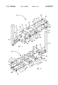
- FIG. 1 is a perspective view of the pump of this invention
- FIG. 2 is a perspective view of the pump of this invention, taken from the opposite side;
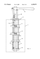
- FIG. 3 is a side view
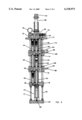
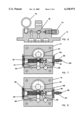
- FIG. 4 is a cross-section taken on lines 4--4 of FIG. 3;
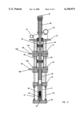
- FIG. 5 is a cross-section taken on lines 5--5 of FIG. 3;
- FIG. 6 is a cross-section taken on lines 6--6 of FIG. 4;
- FIG. 7 is a cross-section taken on lines 7--7 of FIG. 3;
- FIG. 8 is a cross-section taken on lines 8--8 of FIG. 3;
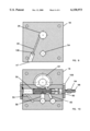
- FIG. 9 is a cross-section taken on lines 9--9 of FIG. 3.
- FIG. 10 is a cross-section taken on lines 10--10 of FIG. 3, after piston displacement.
- the pump 10 of this invention placed in a vented hydraulic fluid container 11.
- the standard fluid container in use today in the shoring industry holds about 5 to 7 gallons of fluid.
- the pump as shown in this embodiment, comprises four blocks, upper block 12, second stage block 14, first stage block 16, third stage block 18, plus base 20.
- the pump as shown has three stages but could have from two to as many stages as are required to reach the desired volume and pressure.
- Blocks 12, 14, 16, 18, and base 20 are held together by a plurality of long bolts 30, 31, 32 and 33 which run the entire length of the pump. Spacers may be used between each block to maintain separation distances.
- the pump also comprises three cyliders, the first stage or high volume cylinder 22, the second stage or medium volume cylinder 24, and the high pressure, low volume cylinder 26.
- the pump for best operation, is bolted, by a plurality of bolts, see bolt holes 28, to the top of container 11 and container 11 is filled with a fluid such as water containing hydraulic oil, or other fluid, submerging the pump partially in the fluid.
- a fluid such as water containing hydraulic oil, or other fluid, submerging the pump partially in the fluid.
- a hydraulic hose is attached, at one end to output port 35 of the pump and at the opposite end to the working shore.
- piston rod 36 When handle 34 is lifted (up-stroke) piston rod 36 is pulled upward, creating a vacuum in the system, exerting a compression force on spring 38 of check valve 40 in intake port 42 located in high pressure intake tube 41, opening check valve 40, allowing fluid to fill high pressure cylinder 26.
- piston rod 36 which has piston head 78 in cylinder 24 and piston head 80 in cylinder 22
- fluid similarly also enters via intake port 68, through check valve 39, which may optionally have a spring, to tubes 54, 52, and 50 and through ports 58 and 64 into cylinders 22 and 24.
- check valve 39 which may optionally have a spring
- Check valves 59, 61, 63, and 65 prevent fluid from passing back down the tubes and cylinders.
- Check valves 39 and 40 similarly prevent fluid from passing back through ports 42 and 68.
- the improvement in the pump in this disclosure is that, when the fluid pressure reaches a preset level, such as 300 psi, as shown in FIG. 10, the first stage pressure control piston 56 located inside of block 16 displaces against adjustable gas and/or fluid controlled piston 90 to close input port 58 preventing all fluid from entering into high volume cylinder 22 and opens exhaust pressure release port 60 to exhaust the fluid into exhaust tubes 51 and 49, and out exhaust port 110, thus disabling high volume cylinder 22. Exhaust port 60 will remain open until the pressure falls below the predetermined fluid pressure. After all fluid has been exhausted through exhaust tube 51, only air will be pumped into and out of cylinder 22 on succeeding strokes. Exhaust port 110 may be located anywhere along the line of tubes 49 and 51.
- cylinders 24 and 26 continue to pump fluid.
- cylinders 24 and 26 continue to increase the system pressure until the fluid pressure reaches another level, such as 1,200 psi.
- second stage pressure release piston 62 in block 14 is displaced against gas or fluid controlled piston 92 to close input port 64 preventing all fluid from entering into medium volume cylinder 24 and opens exhaust pressure release port 66 to exhaust the fluid into exhaust tube 51 and 49 and out exhaust port 110, thus disabling medium volume cylinder 24. This completes the second stage.
- pistons 90 and 92 can be replaced by a sealing device, such as an O-ring on pistons 56 and 62, sealing the gas and/or fluid on the gas and/or fluid side of pistons 56 and 62, preventing the gas and/or fluid from exiting exhaust ports 60 and 66.
- a sealing device such as an O-ring on pistons 56 and 62, sealing the gas and/or fluid on the gas and/or fluid side of pistons 56 and 62, preventing the gas and/or fluid from exiting exhaust ports 60 and 66.
- the third and final stage comprises low volume, high pressure cylinder 26 continuing to pump fluid as the operator continues to pump handle 34, increasing the pressure of the system from 1,200 psi up to the required final pressure desired, which can be as high as 6000 psi, or even higher.
- the high volume cylinder 22 is from about 5 cubic inches to about 7 cubic inches
- the medium volume cylinder 24 from about 1 cubic inch to about 2 cubic inches
- the high pressure cylinder 26 from about 0.5 cubic inches to about 1 cubic inch.
- the volume stated is measured by the total volume of the cylinder less the volume taken up by piston 36 located in cylinders 22 and 24 only.
- FIG. 9 there is shown block 18 with high pressure cylinder 26, port 108 connected to tube 48 and communication line 45 to pass fluid from high pressure cylinder 26 through communication line 45 up tubes 48, 46, and 44 and out output port 35.
- Passageway 47 is needed only to machine communication line 45 and passageway 47 is plugged, once communicaion line 45 has been machined.
- Input ports 42 and 68 are shown in the vertical position rather than the horizontal position shown in my parent application, however they could be in the horizontal position. All input ports may contain filters to filter out unwanted impurities that might negatively affect the operation of the pump. In the alternative, a filter could be placed around the entire outside perimeter of the pump, from block 18 down to base 20.
- Gas and/or fluid input control valves 94 and 96 fitted through caps 104 and 106 are filled through lines 98 and 100, with air and/or fluid, to the pressure desired.
- control valves 94 and 96 may be placed on the top of the higher volume blocks, rather than on the side as shown, which would reduce the width of the pump, providing greater clearance.
- the pump can be removed, so that it can be used elsewhere, by releasing the fitting on the shore, which has a check valve to hold the fluid pressure in the shore.
- the shore equipment must be inserted in the trench and brought to a specific preselected pressure. Too little pressure or too much pressure both will have a negative effect on maintaining the sides of the trench in a safe condition.
Abstract
Description
Claims (10)
Priority Applications (1)
| Application Number | Priority Date | Filing Date | Title |
|---|---|---|---|
| US09/536,227 US6158973A (en) | 1998-03-26 | 2000-03-27 | Multi-stage manual hydraulic pump |
Applications Claiming Priority (2)
| Application Number | Priority Date | Filing Date | Title |
|---|---|---|---|
| US09/048,964 US6079956A (en) | 1998-03-26 | 1998-03-26 | Multi-stage hydraulic pump |
| US09/536,227 US6158973A (en) | 1998-03-26 | 2000-03-27 | Multi-stage manual hydraulic pump |
Related Parent Applications (1)
| Application Number | Title | Priority Date | Filing Date |
|---|---|---|---|
| US09/048,964 Continuation-In-Part US6079956A (en) | 1998-03-26 | 1998-03-26 | Multi-stage hydraulic pump |
Publications (1)
| Publication Number | Publication Date |
|---|---|
| US6158973A true US6158973A (en) | 2000-12-12 |
Family
ID=46255690
Family Applications (1)
| Application Number | Title | Priority Date | Filing Date |
|---|---|---|---|
| US09/536,227 Expired - Lifetime US6158973A (en) | 1998-03-26 | 2000-03-27 | Multi-stage manual hydraulic pump |
Country Status (1)
| Country | Link |
|---|---|
| US (1) | US6158973A (en) |
Cited By (3)
| Publication number | Priority date | Publication date | Assignee | Title |
|---|---|---|---|---|
| WO2002055173A1 (en) * | 2001-01-09 | 2002-07-18 | Teknowsmartz Innovations Techn | Regenerative, multi-stage, fixed recovery pump for filtration systems |
| US20100034678A1 (en) * | 2007-02-19 | 2010-02-11 | Fredericus Johannes Weber | Variable Ratio Hand Pump |
| CN105238682A (en) * | 2015-09-24 | 2016-01-13 | 上海化工研究院 | Straight-through multistage piston type ultrahigh-pressure micro-sample treatment device and application thereof |
Citations (10)
| Publication number | Priority date | Publication date | Assignee | Title |
|---|---|---|---|---|
| US3628567A (en) * | 1969-06-14 | 1971-12-21 | Itt | Power control valve |
| US3747473A (en) * | 1971-03-18 | 1973-07-24 | Bendix Corp | Closed center booster with two-stage hydraulic reaction |
| US3787147A (en) * | 1972-12-26 | 1974-01-22 | Owatonna Tool Co | Two-stage air-hydraulic booster |
| US3896620A (en) * | 1974-01-14 | 1975-07-29 | Gen Motors Corp | Two-stage accumulator valve |
| US3908701A (en) * | 1973-06-22 | 1975-09-30 | Westinghouse Electric Corp | Three stage, double tapered dashpot |
| US4278574A (en) * | 1977-12-27 | 1981-07-14 | Vianova Kunstharz, A.G. | Polysiloxane-modified paint binders and process for producing the binders |
| US4287813A (en) * | 1979-12-20 | 1981-09-08 | International Harvester Company | Two-stage concentric hydraulic brake booster |
| US4850828A (en) * | 1986-11-21 | 1989-07-25 | Kabushiki Kaisha Kosmek | Plunger pump of quick pressure-rise type |
| US5207726A (en) * | 1991-08-06 | 1993-05-04 | Christopher Rathweg | Hydraulic pump |
| US5575627A (en) * | 1995-01-12 | 1996-11-19 | Hyvair Corporation | High and low pressure two stage pump and pumping method |
-
2000
- 2000-03-27 US US09/536,227 patent/US6158973A/en not_active Expired - Lifetime
Patent Citations (10)
| Publication number | Priority date | Publication date | Assignee | Title |
|---|---|---|---|---|
| US3628567A (en) * | 1969-06-14 | 1971-12-21 | Itt | Power control valve |
| US3747473A (en) * | 1971-03-18 | 1973-07-24 | Bendix Corp | Closed center booster with two-stage hydraulic reaction |
| US3787147A (en) * | 1972-12-26 | 1974-01-22 | Owatonna Tool Co | Two-stage air-hydraulic booster |
| US3908701A (en) * | 1973-06-22 | 1975-09-30 | Westinghouse Electric Corp | Three stage, double tapered dashpot |
| US3896620A (en) * | 1974-01-14 | 1975-07-29 | Gen Motors Corp | Two-stage accumulator valve |
| US4278574A (en) * | 1977-12-27 | 1981-07-14 | Vianova Kunstharz, A.G. | Polysiloxane-modified paint binders and process for producing the binders |
| US4287813A (en) * | 1979-12-20 | 1981-09-08 | International Harvester Company | Two-stage concentric hydraulic brake booster |
| US4850828A (en) * | 1986-11-21 | 1989-07-25 | Kabushiki Kaisha Kosmek | Plunger pump of quick pressure-rise type |
| US5207726A (en) * | 1991-08-06 | 1993-05-04 | Christopher Rathweg | Hydraulic pump |
| US5575627A (en) * | 1995-01-12 | 1996-11-19 | Hyvair Corporation | High and low pressure two stage pump and pumping method |
Cited By (5)
| Publication number | Priority date | Publication date | Assignee | Title |
|---|---|---|---|---|
| WO2002055173A1 (en) * | 2001-01-09 | 2002-07-18 | Teknowsmartz Innovations Techn | Regenerative, multi-stage, fixed recovery pump for filtration systems |
| US20100034678A1 (en) * | 2007-02-19 | 2010-02-11 | Fredericus Johannes Weber | Variable Ratio Hand Pump |
| US8287251B2 (en) | 2007-02-19 | 2012-10-16 | Actuant Corporation | Variable ratio hand pump |
| CN105238682A (en) * | 2015-09-24 | 2016-01-13 | 上海化工研究院 | Straight-through multistage piston type ultrahigh-pressure micro-sample treatment device and application thereof |
| CN105238682B (en) * | 2015-09-24 | 2017-08-11 | 上海化工研究院有限公司 | A kind of device of straight-through Multi-stage piston type ultra high pressure treatment micro-example and application |
Similar Documents
| Publication | Publication Date | Title |
|---|---|---|
| US6089837A (en) | Pump inlet stabilizer with a control unit for creating a positive pressure and a partial vacuum | |
| US5584664A (en) | Hydraulic gas compressor and method for use | |
| EP1344946A3 (en) | Double-acting pressure intensifying cylinder and method for intensifying pressure in the cylinder | |
| US6017170A (en) | Adjustable self locking shoring strut | |
| US5139390A (en) | Pump and method for drawing vapor from a storage tank without forcibly drawing the vapor from the tank | |
| US6158973A (en) | Multi-stage manual hydraulic pump | |
| JP3094032B2 (en) | Means for receiving hydraulic oil into the hydraulic system and then discharging it from the hydraulic system | |
| US6079956A (en) | Multi-stage hydraulic pump | |
| US3653302A (en) | Hydraulic lift mechanism | |
| EP0075595A1 (en) | Unloading system for cryogenic pumps | |
| CN205715070U (en) | A kind of pneumatic oil draining system of hydraulic jack | |
| US2862448A (en) | Fluid operated well pumps | |
| US5575627A (en) | High and low pressure two stage pump and pumping method | |
| NO865149L (en) | PRESSURE FEED EQUIPMENT. | |
| US4089165A (en) | Water pressure-powered pile driving hammer | |
| KR20030053699A (en) | Cylinder Tester | |
| US2933043A (en) | Well pump | |
| SU1707231A1 (en) | Piston compressor with hydraulic drive | |
| RU2016235C1 (en) | Apparatus of oil well rod type pump | |
| US1666255A (en) | Hydraulic pumping power | |
| US4779843A (en) | Jack with drain valve | |
| CA2035539C (en) | Vapour transfer pump | |
| GB2141180A (en) | Pumping apparatus | |
| RU2639454C2 (en) | Device for dynamic pressure increase with function for smoothing pulsations of hydraulic liquid | |
| SU477658A1 (en) | Device for hydraulic testing of products |
Legal Events
| Date | Code | Title | Description |
|---|---|---|---|
| AS | Assignment |
Owner name: TRENCH PLATE RENTAL CO., INC., CALIFORNIA Free format text: ASSIGNMENT OF ASSIGNORS INTEREST;ASSIGNOR:MALISZEWSKI, JOHN L.;REEL/FRAME:010658/0399 Effective date: 20000321 |
|
| STCF | Information on status: patent grant |
Free format text: PATENTED CASE |
|
| FPAY | Fee payment |
Year of fee payment: 4 |
|
| FPAY | Fee payment |
Year of fee payment: 8 |
|
| FPAY | Fee payment |
Year of fee payment: 12 |
|
| AS | Assignment |
Owner name: FIFTH THIRD BANK, AS ADMINISTRATIVE AGENT, OHIO Free format text: SECURITY INTEREST;ASSIGNOR:TRENCH PLATE RENTAL CO.;REEL/FRAME:040021/0296 Effective date: 20161014 |
|
| AS | Assignment |
Owner name: MUFG UNION BANK, N.A., AS AGENT, CALIFORNIA Free format text: SECURITY INTEREST;ASSIGNOR:TRENCH PLATE RENTAL CO.;REEL/FRAME:049620/0409 Effective date: 20190627 |
|
| AS | Assignment |
Owner name: TRENCH PLATE RENTAL CO., CALIFORNIA Free format text: RELEASE BY SECURED PARTY;ASSIGNOR:FIFTH THIRD BANK, AS AGENT;REEL/FRAME:049645/0904 Effective date: 20190627 |
|
| AS | Assignment |
Owner name: TRENCH PLATE RENTAL CO., CALIFORNIA Free format text: NOTICE OF RELEASE OF SECURITY INTEREST IN PATENTS;ASSIGNOR:MUFG UNION BANK, N.A. AS AGENT;REEL/FRAME:054585/0424 Effective date: 20201203 |
|
| AS | Assignment |
Owner name: MIDCAP FINANCIAL TRUST, AS COLLATERAL AGENT, MARYLAND Free format text: INTELLECTUAL PROPERTY SECURITY AGREEMENT (PATENTS));ASSIGNOR:TRENCH PLATE RENTAL CO.;REEL/FRAME:054593/0367 Effective date: 20201203 |
|
| AS | Assignment |
Owner name: TRENCH PLATE RENTAL CO., TEXAS Free format text: RELEASE BY SECURED PARTY;ASSIGNOR:MIDCAP FINANCIAL TRUST, AS COLLATERAL AGENT;REEL/FRAME:059712/0537 Effective date: 20220429 Owner name: MIDCAP FINANCIAL TRUST, AS COLLATERAL AGENT, MARYLAND Free format text: SECURITY INTEREST;ASSIGNOR:TRENCH PLATE RENTAL CO.;REEL/FRAME:059711/0861 Effective date: 20220429 |