US6161209A - Joint detector for multiple coded digital signals - Google Patents
Joint detector for multiple coded digital signals Download PDFInfo
- Publication number
- US6161209A US6161209A US08/827,533 US82753397A US6161209A US 6161209 A US6161209 A US 6161209A US 82753397 A US82753397 A US 82753397A US 6161209 A US6161209 A US 6161209A
- Authority
- US
- United States
- Prior art keywords
- estimates
- detector
- digital signals
- performance
- users
- Prior art date
- Legal status (The legal status is an assumption and is not a legal conclusion. Google has not performed a legal analysis and makes no representation as to the accuracy of the status listed.)
- Expired - Lifetime
Links
Images


Classifications
-
- H—ELECTRICITY
- H03—ELECTRONIC CIRCUITRY
- H03M—CODING; DECODING; CODE CONVERSION IN GENERAL
- H03M13/00—Coding, decoding or code conversion, for error detection or error correction; Coding theory basic assumptions; Coding bounds; Error probability evaluation methods; Channel models; Simulation or testing of codes
- H03M13/63—Joint error correction and other techniques
- H03M13/6306—Error control coding in combination with Automatic Repeat reQuest [ARQ] and diversity transmission, e.g. coding schemes for the multiple transmission of the same information or the transmission of incremental redundancy
-
- H—ELECTRICITY
- H03—ELECTRONIC CIRCUITRY
- H03M—CODING; DECODING; CODE CONVERSION IN GENERAL
- H03M13/00—Coding, decoding or code conversion, for error detection or error correction; Coding theory basic assumptions; Coding bounds; Error probability evaluation methods; Channel models; Simulation or testing of codes
- H03M13/29—Coding, decoding or code conversion, for error detection or error correction; Coding theory basic assumptions; Coding bounds; Error probability evaluation methods; Channel models; Simulation or testing of codes combining two or more codes or code structures, e.g. product codes, generalised product codes, concatenated codes, inner and outer codes
- H03M13/2957—Turbo codes and decoding
- H03M13/296—Particular turbo code structure
- H03M13/2963—Turbo-block codes, i.e. turbo codes based on block codes, e.g. turbo decoding of product codes
-
- H—ELECTRICITY
- H03—ELECTRONIC CIRCUITRY
- H03M—CODING; DECODING; CODE CONVERSION IN GENERAL
- H03M13/00—Coding, decoding or code conversion, for error detection or error correction; Coding theory basic assumptions; Coding bounds; Error probability evaluation methods; Channel models; Simulation or testing of codes
- H03M13/03—Error detection or forward error correction by redundancy in data representation, i.e. code words containing more digits than the source words
- H03M13/05—Error detection or forward error correction by redundancy in data representation, i.e. code words containing more digits than the source words using block codes, i.e. a predetermined number of check bits joined to a predetermined number of information bits
- H03M13/09—Error detection only, e.g. using cyclic redundancy check [CRC] codes or single parity bit
- H03M13/098—Error detection only, e.g. using cyclic redundancy check [CRC] codes or single parity bit using single parity bit
-
- H—ELECTRICITY
- H03—ELECTRONIC CIRCUITRY
- H03M—CODING; DECODING; CODE CONVERSION IN GENERAL
- H03M13/00—Coding, decoding or code conversion, for error detection or error correction; Coding theory basic assumptions; Coding bounds; Error probability evaluation methods; Channel models; Simulation or testing of codes
- H03M13/03—Error detection or forward error correction by redundancy in data representation, i.e. code words containing more digits than the source words
- H03M13/05—Error detection or forward error correction by redundancy in data representation, i.e. code words containing more digits than the source words using block codes, i.e. a predetermined number of check bits joined to a predetermined number of information bits
- H03M13/13—Linear codes
- H03M13/19—Single error correction without using particular properties of the cyclic codes, e.g. Hamming codes, extended or generalised Hamming codes
Definitions
- This invention relates to the joint detection of multiple digital signals that are forward error correction coded and share the same transmission medium in a manner that causes mutual interference. More specifically, the present invention relates to a novel method for detection that allows the permissible interference to be increased and bandwidth to be conserved.
- the frequency spectrum is re-used in a variety of ways.
- the traditional approach is to physically isolate communications signals of the same frequency in order to reduce their mutual interference to acceptable levels.
- Less traditional approaches use spread spectrum techniques to average the effects of interference over a bandwidth significantly greater than the information bandwidth. In both of these cases, interference will exist to some extent and, in some cases, can significantly reduce the system capacity, i.e., the information/unit time/unit bandwidth.
- Viterbi in a paper entitled “Very low rate convolutional codes for maximum theoretical performance of spread-spectrum multiple-access channels", IEEE J. Sel. Areas Comm., vol. 8, no.4, pp.641-649, May 1990, but it has the drawback that it treats the digital signals asymmetrically and requires some co-ordination between transmitters.
- An alternative approach to joint detection of multiple coded digital signals that is known to be optimum in a maximum likelihood sense for certain types of forward error correction codes, is described by T. R. Giallorenzi and S. G. Wilson, in a paper entitled “Multiuser ML sequence estimator for convolutional coded asynchronous DS-CDMA systems," IEEE Trans. Comm., vol. 44, No. 8, pp.997-1008, August 1996.
- It is an object of this invention is to reduce the effects of the interference between a multiplicity of coded digital signals sharing the same transmission medium so as to permit greater interference and conserve bandwidth.
- the present invention provides an iterative method for reliably estimating multiple coded digital signals that share the same medium causing mutual interference.
- the digital signals in general, come from different sources but they need not.
- the method is comprised of two steps that are applied to preliminary estimates of each digital signal, one or more times. There are various known methods of obtaining these preliminary estimates. In many cases, the best approach is to detect each digital signal as if it were the only digital signal present in the transmission medium. The performance of the present invention will depend upon the quality of these preliminary estimates. With regard to the approach taken to obtain these preliminary estimates, the present invention relies only on a statistical model of the interference between these preliminary estimates.
- the first step of the method is to provide reliability estimates for each data element of each digital signal using the preliminary estimates, a statistical model for the interference, and any a priori information regarding the data elements.
- This interference model corresponds to the statistical distribution of the preliminary estimates assuming the transmitted data is known.
- the reliability estimate is defined as the conditional probability of the data elements given the interference model, the preliminary estimates, and the a priori information. On the first iteration there is often no a priori information and the reliability estimates are based on the preliminary estimate and the interference model. For binary data elements, the resulting reliability estimate is often expressed as the probability that the data element is a "0" or a "1". Properties of the forward error correction coding are not used in this step.
- the second step of the method is to revise these reliability estimates for each digital signal based on the forward error correction code used for that digital signal.
- decoders that revise the symbol reliabilities are often called soft-output decoders.
- the revised probability estimates are the conditional probabilities of the data elements given the reliabilities of all the data elements for that digital signal, and the relationships between them, as defined by the forward error correction code.
- the digital signals are independently decoded. This results in a significant computational saving over joint decoding.
- the subsequent iterations use the revised reliability estimates for each data element of each digital signal obtained from the second step as a priori information for the first step. This improves the performance of the latter, which in turn can be used to improve the performance of the second step.
- the decoders of the second step are configured to produce reliability estimates or hard decisions corresponding to the information elements of those digital signals of interest.
- the information elements may or may not be explicitly contained in the data elements of each digital signal, but they may be always be estimated through the knowledge of the forward error correction code.
- a method is provided of detecting a plurality of digital signals that are forward error correction encoded and mutually interfere. The method comprises the steps of:
- step (b) repeating the previous two steps, one or more times, using the revised reliability estimates provided by step (c) as a priori information for step (b).
- a system of detecting a plurality of digital signals that are forward error correction encoded and mutually interfere, given preliminary estimates of those signals, comprising: means for calculating a reliability estimate for each data element of each digital signal in dependence upon the preliminary estimates of those data elements, a statistical model of the interference, and a priori information, if any, concerning those data elements; and, for calculating a revised reliability estimate for each data element based on the reliability estimates calculated and the properties of the forward error correction code for the corresponding digital signal.
- the present invention can be applied to digital signals in any shared transmission medium, or in distinct transmission media where there is crosstalk between the media.
- FIG. 1 is schematic block diagram of a communication system to which the present invention can be applied;
- FIG. 2 is a schematic block diagram of an iterative joint detector for multiple decoded signals
- FIG. 3 is flow chart of the steps required for obtaining reliability estimates
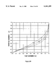
- FIG. 4 is a graph illustrating performance of present invention in a synchronous Gaussian channel for the case of five digital signals with a pairwise correlation of 0.75;
- FIG. 5 is a block diagram illustrating a serial implementation of this invention.
- FIG. 6 is a block diagram illustrating an alternative serial implementation to that shown in FIG. 5;
- FIG. 7 is a block diagram illustrating the use of multiple preliminary estimates, in accordance with this invention.
- FIG. 8 is a block diagram illustrating a feedback arrangement for implementing each iteration of the method
- FIG. 10 is a diagram of a trellis structure for four-states
- FIG. 11 represents a comparison between bit error rate performance of two algorithms, BCJR and MLSE, in additive white Gaussian noise for two convolutional codes
- FIG. 12 is a diagram comparing the BER performance of SPC component codes and uncoded performance in additive white Gaussian noise
- FIG. 13 is an informative to plot the same results as a function of the energy per channel bit to noise density ratio, E s /N 0 , that is uncompensated for the code rate;
- FIG. 14 is an illustration of parallel concatenated coding
- FIG. 15 shows a typical two-dimensional product code
- FIG. 16 is a block diagram of an approach applied to a two-dimensional product code shown in FIG. 15 where each row and each column of this code is a codeword in the (n,k) component block code;
- FIG. 17 is a diagram of performance of an iterative decoding strategy
- FIG. 18 is a diagram illustrating performance using various decoding strategies
- FIG. 19 illustrates that Turbo coding is a parallel coding scheme
- FIG. 20 is an illustration of the original Turbo component code
- FIG. 21 is a block diagram of a Turbo Code decoder structure
- FIG. 22 is a diagram illustrating performance of Turbo Codes
- FIG. 23 is an illustration of iterative search between different constraint sets
- FIG. 24 is an illustration of Turbo detection algorithm showing difference operations and the interleaver (I) and de-interleaver (D) operations;
- FIG. 25 is an illustration of extrinsic form of the Turbo detection algorithm
- FIG. 26 is an illustration of a geometric interpretation of the modified MCE algorithm:
- FIG. 27 is an illustration of structure of multiuser communication system
- FIG. 28 is an illustration of a finite-state machine representation of multi-user channel with Viterbi detection
- FIG. 30 is a graph of asymptotic efficiency for two equal-power users as a function of user cross-correlation ( ⁇ ) for various synchronous detectors;
- FIG. 33 is a block diagram of limiting asynchronous decorrelating receiver
- FIG. 36 is an illustration of Varanasi-Aazhang multistage interference cancellation algorithm
- FIG. 37 is an illustration of multi-user array processing algorithm
- FIG. 38 is a diagram of theoretical bound on single user capacity for a Gaussian multiple access channel with K users having the same rate and SNR;
- FIG. 39 is a diagram of asymptotic efficiencies of conventional, decorrelating, and optimum detectors as a function of the number of users (K) and the cross-correlation parameter ( ⁇ );
- FIG. 42 is an illustration of conventional and decorrelating detector structures for multiuser signals with forward error correction coding
- FIG. 44 is a plot of the BER performance of decorrelating detector with rate 1/2 convolutional code for different numbers of users (K) and cross-correlation parameters ( ⁇ ). (Code generators: [10011 11101]);
- FIG. 45 is an illustration of iterative multiuser detection algorithm
- Interleaver contains 500 information bits:
- Interleaver contains 500 information bits;
- FIG. 56 is an illustration of co-channel interference with multi-beam satellites
- FIG. 57 is a simplified diagram of a process structure for multiuser detection with spatial diversity
- FIG. 58 is a diagram of asymptotic efficiency of different detectors over K-symmetric diversity channel for 2, 5, and 10 users;
- FIG. 59 is an illustration of relationship between crosstalk parameter ( ⁇ ) and the user correlation parameter ( ⁇ );
- FIG. 65 is a simplified diagram of theoretical capacity of K-symmetric channel with diversity for different correlation values and five users, in bits per channel use per user.
- the present invention is a method of processing the received signal samples obtained when multiple coded signals share the same transmission medium.
- An example of a communications system to which this invention can be applied is illustrated in FIG. 1.
- These signaling waveforms may include filtering, frequency translations, spreading codes, etc.
- the signaling waveforms need not he unique.
- These signals then enter the transmission medium and may suffer corresponding delays and attenuation, and be degraded by noise.
- the communications receiver has K parallel subreceivers, one for each digital signal.
- these subreceivers provide preliminary estimates of the data elements of each digital signal. These preliminary estimates are often called soft decisions in the technical literature.
- the best subreceiver is one that is matched to the signaling waveform for the corresponding digital signal, ignoring the presence of the other digital signals. This matching refers not only to the transmitted signaling waveform but also any delay, frequency translation, or phase rotation that may have been incidentally applied to the signal after transmission.
- the present invention also applies to non-optimum subreceivers. The output of these matched detectors is then sampled, once per data element period, to produce a soft decision for each data element in the corresponding digital signal.
- the present invention is a method of processing the preliminary estimates provided by these K subreceivers to reduce the effects of interference.
- An exemplary arrangement for the processing performed in the present invention is shown in FIG. 2.
- the digital signals have the same signaling rate and are synchronous.
- Let b(i) be the vector of K symbols, one from each digital signal, with a common symbol time i, and let y(i) be the corresponding vector of K preliminary estimates from the K subreceivers.
- the statistical model for the interference in this case, is the conditional distribution of y(i) given the transmitted data b(i). If the noise is Gaussian then, in this case, the conditional distribution of y(i) given b(i) is multivariate Gaussian for the symbol time i and independent from one symbol time to the next.
- the first step of the invention requires a means for estimating reliability of the data elements of each of the digital signals.
- the conventional approach is to use Bayes' rule for conditional probability, one then computes the reliability estimate (conditional probability) of each data element of each digital signal that is based only on the vector of preliminary estimates y(i), the statistical model for the interference, and the a priori information regarding those data elements.
- joint reliability estimates for the K digital signals is given by ##EQU1##
- the reliability estimates for the individual digital signals are given by the corresponding marginal distributions. This constitutes the first step. Exemplary steps for determining these reliability estimators are shown in FIG. 3.
- each digital signal is considered independent of the others. As shown in FIG. 2, this can be implemented as K parallel decoders.
- the reliability estimates provided by the first step are revised based on the known relationships between data elements. These known relationships are due to the forward error correction encoding.
- a preferred means for soft-output decoding is described by L. R. Bahl, J. Cocke, F. Jelinek, and J. Raviv, in a paper entitled "Optimal decoding of linear codes for minimizing symbol error rate," IEEE Trans. Inf. Th., vol. 20, pp.284-287, March 1974.
- the revised reliability estimates provided by the second step are used as a priori probabilities in the first step.
- the revised reliability estimates are treated as independent of one another; and in the preferred embodiment, not all of the revised reliability estimates provided by the second step first stage are used in each first step calculation.
- the first step reliability estimates for a particular digital signal only use the a priori information for those digital signals other than the one of interest.
- the present invention does not require that the digital signals are synchronous. However, it is recommended that the interference model for the preliminary estimates include the effects of any asynchronism.
- the complexity of the present invention depends in part on the complexity of this interference model. There is the possibility of reducing the complexity by appropriate design of the K subreceivers. If the digital signals are not only asynchronous but also have different signaling rates then to optimize performance may require oversampling of the received signal, and constructing a corresponding interference model. Oversampling is defined as sampling at a rate higher than the transmission rate of the data elements.
- the present invention does not require that all data sequences use the same forward error correction code.
- the use of different error correction codes will only affect the second step of the method.
- the digital signals are asynchronous or the data sequences have different lengths then the direct implementation of the soft decoding method of L. R. Bahl et al, may not be appropriate.
- the soft decoding techniques can be applied to a series of overlapping blocks where the block size is less than the sequence length.
- the digital signals are not required to have the same modulation format. There are no particular issues associated with different modulation formats except to note that in the exemplary communications shown in FIG. 1, the sampling will correspond to sampling both the in phase and quadrature components of a digital signal with some modulation formats. With a binary modulation format, only the reliability of the data element "1" or a "0", but not both, needs to be stored; while with a M-ary modulation formats, at least M-1 or M reliability values should be stored corresponding to the M possible values for each data element.
- the invention also applies when the digital signals have the same, different, or even time-varying power levels.
- the latter may be due to different propagation losses, fading and multi-path.
- the available knowledge concerning the power levels and time-variations, whether it be deterministic or statistical, should be included in the interference model.
- Complexity may often be an issue in either the first or the second step of the method.
- simplifications are made to the interference model to reduce this complexity. These simplifications often result from a consideration of a subset of the available data in the model. For example, for each digital signal, the interference model may only consider the interference from the two strongest interferers and ignore the effects of the other signals.
- simplifications can often be made to the decoding technique to reduce the complexity. These simplifications often result from considering only a subset of the available data. For example, some simplified decoding techniques only consider the most probable sequences (paths) at each step and ignore the less probable ones. In practice, there is usually a tradeoff between complexity and performance.
- the parallel implementation shown in FIG. 2 is one implementation of this invention; however, the invention can also be implemented serially.
- FIG. 8 the invention does not need to be implemented with distinct hardware or software for each iteration of the method as may be suggested by FIG. 2.
- FIG. 5 a serial implementation is shown that decodes only one signal at the second step, selecting a different one of the K digital signals for each second step.
- any number from one to all of the K digital signals is decoded on execution of the second step.
- the signals need not be decoded in any particular order, nor do all signals have to be decoded an equal number of times.
- An alternative serial implementation is shown in FIG. 6. In this case, two decodings are performed with each second step but the decoded digital signals are not distinct on subsequent decodings.
- the phrase "Means for soft-output decoding k" indicates a means for soft-output decoding of digital signal k.
- any existing interference cancellation method for uncoded signals can be applied, prior to this invention, to provide the preliminary estimates.
- the only requirement is that the interference model applies to the preliminary estimates after the initial interference cancellation, if any, is done.
- the invention is also applicable when there are multiple preliminary estimates of the signal such as may occur when one has a number of distinct receivers. This is known in the literature as diversity reception. There are a number of ways to use the multiple preliminary estimates according to the invention. The simplest approach is using a means of combining the multiple estimates into a single estimate prior to this invention. This is illustrated in FIG. 6.
- a trellis structure is a requirement of both the BCJR and the Viterbi algorithm still providing a rich collection of codes upon which to draw.
- the transmitted bits will be grouped together into T symbols, v.sub.[1,T]. This grouping arises naturally from the code structure. For example, with a rate 1/2 code, T is N/2.
- the detection algorithm provides an estimate x of the data based on the sequence y (or w) and knowledge of the FEC code. Initially, the channel is assumed to be the additive white Gaussian noise channel.
- the channel encoder is assumed to have a trellis structure such as that illustrated in FIG. 10 for four-states. It is assumed that the trellis starts and ends in the zero state, and that the appropriate null bits are added to the information stream to insure proper termination of the trellis. In general, it is assumed that the block lengths are long enough to make the effect of truncation on the code properties negligible.
- the number of trellis transitions, T, corresponding to the N codebits is a function of the encoding strategy. Its relationship to the index of the channel bits or the information bits will depend upon the code rate and how the trellis is truncated.
- Each channel symbol, v(t) corresponds to a state transition from s(t-1) to s(t). For example with a rate 2/3 binary convolutional code, each channel symbol will have three bits and each pair of information bits will correspond to a state transition until one reaches the termination stage. In the termination stage, "0" information bits are appended to the input and the corresponding channel symbols are generated until the trellis returns to the all-zero state.
- the objective is to determine that x which maximizes the conditional probability Pr[x
- this conditional probability is a product of independent Gaussian distributions, and this maximization algorithm can be solved by the Viterbi algorithm [Pro89].
- the Viterbi algorithm is a maximum-likelihood decoder which minimizes the probability of codeword or sequence error. It does not, necessarily, minimize the probability of symbol or bit error.
- the BCJR algorithm is an optimal decoder which minimizes the symbol error probability for linear codes transmitted over a discrete memoryless channel (DMC).
- the BCJR algorithm can provide the probabilities: Pr[x(j)
- the algorithm includes a backward and forward recursion unlike the Viterbi algorithm, which only contains a forward recursion. Below, a modified but equivalent version of this algorithm is presented. The modifications are two-fold; the first changes the quantities to which the recursion are applied to make them more amenable to analysis and also make them symmetric in the backward and forward direction; the second extends the results to cover the memoryless Gaussian channel.
- the code can be represented as a trellis, such as illustrated in FIG. 10, where the next state depends only on the current state and the new input bit.
- the state of the trellis at time t is denoted by s(t), and the output symbol due to the transition from s(t-1) to s(t) is denoted by v(t).
- a state sequence from time t to t' is denoted by s t ,t', and the corresponding output sequence is v.sub.[t,t'].
- Theorem 1.2 (Recursion Theorem).
- the forward and backward estimates can be determined recursively as follows. ##EQU5## and ##EQU6##
- the decoder computes ⁇ (t), and then ⁇ (t) using (11). The obtained values of ⁇ (t) are stored for all t and m.
- the decoder recursively computes ⁇ (t) using (12). When the ⁇ (t) have been computed they can be multiplied by the appropriate ⁇ (t) to obtain ⁇ (t) using (8).
- the BCJR algorithm is a double recursion, one recursion in the forward direction and one in the reverse. Consequently, it has at least twice the complexity of the Viterbi algorithm in its most general form. It also has larger storage requirements as the results of the forward recursion must be stored to be used with the reverse recursion. Hard decisions are derived from the algorithm on the basis of whether the probability a bit is a "1" is greater than 0.5 but the algorithm's main feature is its soft-output capability.
- Parallel concatenated coding implies that same information is encoded by two different encoding schemes as illustrated in FIG. 14. In a sense all systematic parity check codes fit this definition, because they could be written as a set a parallel single parity check equations, although generally more powerful component codes are considered.
- FIG. 15 A typical two-dimensional product code is illustrated in FIG. 15.
- the bits are arranged in a k ⁇ k square and encoded horizontally using an (n,k) code. The same bits are then encoded vertically using the same (n,k) code.
- the vertical encoding also encodes the parity bits of the horizontal encoding although this is not necessarily the case.
- Prior art implementations involve each dimension being decoded in tu. the check digits are used to correct single errors and then discarded.
- FIG. 16 A block diagram of this approach is shown in FIG. 16 for the two-dimensional product code shown in FIG. 15 where each row and each column of this code is a codeword in the (n,k) component block code. This is an (n 2 ,k 2 ) product code. If the component code has a minimum distance d, then the two-dimensional product code has a minimum distance d 2 .
- the algorithm applies the BCJR algorithm to the soft decisions received for each row to produce the a posteriori probabilities for each channel bit. These output probabilities are used as an input to the column decoding, again using the BCJR algorithm. This process is then repeated with further row and column decodings. It is the transmitted symbol probabilities that are the important quantities for subsequent decodings. At the last stage the BCJR algorithm is modified to produce the a posteriori probabilities of the information bits. In the case where the code is systematic, no modification is necessary.
- this simple rate 3/4 code provides 2 dB or more performance gain for BERs less than 10 -3 with a single iteration. A second iteration results in a further gain of about 0.25 dB. The improvement with subsequent iterations is marginal.
- For single parity check codes there is a simple two-state trellis for each component code and thus the decoding algorithm has very low complexity.
- one iteration of the MAP algorithm provides greater than 2 dB improvement over uncoded performance at a BER of 10 -3 .
- the gain increases with increasing E b /N 0 .
- a second iteration results in a further 2.5 dB improvement in performance.
- the improvement with subsequent iterations was marginal. This was found to be a general rule, i.e for two-dimensional product codes, two iterations achieved most of the gain.
- FIG. 18 Also shown in FIG. 18 is the performance with hard decision decoding of the product code. It is interesting to note that one iteration of the hard decision approach is almost exactly 2 dB worse than one iteration of the soft decision approach over the full range shown. With the hard decision approach, further iterations result in only a marginal improvement as shown.
- Turbo coding is a parallel coding scheme as illustrated in FIG. 19. Similar to FIG. 14, the information is systematically encoded by two encoders. However, unlike the ordered interleaving used with the product codes, the information bits are re-ordered using a pseudo-random interleaver with Turbo codes. Typically the same code is used for both encoders, although this is not necessarily the case.
- the information bits and the parity bits generated by each of the encoders are then transmitted over the channel. In the original Turbo encoding scheme, the parity bits are punctured in a repeating pattern to increase the code rate. Again, this is not necessary.
- the component codes that are recommended for Turbo encoding are the short constraint length, systematic, recursive convolutional codes.
- the original Turbo component code is illustrated in FIG. 20. This is a simple 16-state code.
- the feedback nature of these component codes means that a single bit error corresponds to an infinite sequence of channel errors.
- Turbo codes are inherently block codes with the block size being determined by the size of the interleaver.
- the block nature also raises a practical problem of how to correctly terminate the trellises of both encoders. This problem is avoided for evaluation purposes by using an all-zeros sequence.
- the decoding strategy applied to Turbo codes is also innovative. It is from the structure of the decoding algorithm that the scheme draws its name from an analogy to the turbo engine principle.
- a block diagram of the decoder structure is shown in FIG. 21. It is illustrated as a single iterated stage but also could be implemented as a number of serial stages.
- the inputs to the first decoding stage are the channel samples (u, ⁇ 1 ) corresponding respectively to the systematic bits x, and the channel samples corresponding the parity bits of the first encoder z 1 , and the extrinsic information about the systematic bits that was determined from previous decoder stages ⁇ 2 (x).
- the extrinsic information is zero. If puncturing is applied at the transmitter then the parity bits must be stuffed with zeros in the appropriate positions.
- the first decoding stage uses the BCJR algorithm to produce a refined (soft) estimate of the systematic bits, Pr[x(j)
- this soft estimate is more convenient to express this soft estimate as the equivalent log-likelihood ratio ##EQU7##
- this refined estimate is re-ordered to compensate for the pseudo-random interleaving at the transmitter and combined with the second set of parity samples from the channel as the input to the second decoding stage.
- the second decoding stage uses the BCJR algorithm to produce a further refined estimate of the systematic bits Pr[x(j)
- This second estimate is expressed as the log-likelihood, ⁇ 2 (x(j)).
- This estimate can be hard-detected to provide bit estimates at this point.
- the output of the second stage can be used to provide extrinsic information to the first stage. In either case, the samples must be re-ordered to compensate for the random interleaving.
- Intrinsic information refers to the information inherent in a sample prior to a decoding.
- Extrinsic information refers to the incremental information obtained through decoding. To maintain as much independence as possible from one iteration to the next only extrinsic information is fed from one stage to the next.
- Equation (14) shows that they can be separated easily.
- the first factor in the product on the second line of (14) represents the intrinsic information of the soft channel values at the input to the decoder, and the second term is the extrinsic information which is generated by the decoding. It is more convenient to express this relationship in terms of log-likelihood ratios because then the product becomes a sum and the denominator term cancels.
- the extrinsic information at the output of the second stage is
- the processing performed in the BCJR algorithm is unchanged from the basic algorithm. The differences occur only in the processing which is performed the inputs to and outputs from the BCJR algorithm. A hard decision can be obtained at any time with the operation
- WEF bivariate weight enumerating function
- conditional weight enumerating function Aw C1(Z) of each of the component codes is defined as the distribution of the Hamming weights of the paty check bits for any input word of Hamming weight w, then a relationship between the conditional WEF and the bivariate WEF function is ##EQU10##
- a uniform interleaver of length J is a probabilistic device that maps a given input word of weight w into all distinct ##EQU11## permutations of it with equal probability ##EQU12##
- conditional WEF A w C1 (Z) corresponds to a specific error event where the systematic bits have weight w.
- the second encoder will produce a parity stream of a specified weight. From the definition of the uniform interleaver, this second parity stream is not fixed for a given weight it, error event but rather has a distribution described by ##EQU13## and this is independent of the parity stream of the first encoder. Consequently, the combined parity stream has a conditional WEF given by ##EQU14##
- ⁇ min does not necessarily equal the free distance of the code.
- the number of possible information error events of weight w min in an interleaver of length J is ##EQU18## So over a block of length J, there are ⁇ min J events of distance ⁇ min .
- the fraction of w min events which are the minimum distance ⁇ min is ##EQU19##
- Equation (24) shows that the interleaver gain on the error coefficient is proportional to J 1-w .sbsp.min.
- w min 1. Consequently only for recursive convolutional codes, is there an interleaver gain on the error coefficient.
- other events with w ⁇ w min may have distances ⁇ min but will have a significantly greater attenuation, J 1-w , of the error coefficient.
- the critical design parameters for Turbo codes are not the minimum distance but rather ⁇ min and w min .
- cross-entropy is a measure of the difference between two probability distributions. Traditionally, it has had greater importance in statistical applications than in communications.
- p and q of an alphabet X the cross-entropy is defined as ##EQU21##
- the cross-entropy of two distributions is zero only if the two distributions are identical. Otherwise the cross-entropy is positive.
- the cross-entropy of two distributions is not symmetric, that is,
- the Principle of Maximum Entropy selects that distribution which has the maximum entropy subject to the known constraints on the random variable x.
- the constraints referred to are typically constraints on the range and the moments of x. For example, when a random variable has a range (- ⁇ , + ⁇ ), a mean of zero, and a variance of one, the maximum entropy distribution is the normal distribution.
- Implicit in the principle of maximum entropy is the assumption that there is no a priori information about the random variable other than the constraints.
- the Principle of Minimum Cross-entropy is a generalization of the maximum entropy principle, which permits the inclusion of a priori information.
- the Principle of Minimum Cross-entropy selects that distribution p[x] which has the minimum cross-entropy H[p,q] subject to the known constraints on the random variable x.
- E p is the expectation over the distribution p
- f i are functions in x that represent the equality constraints on the moments of x.
- cross-entropy minimization is a very general statistical inference method. To apply cross-entropy to a decoding problem, determination of a priori distribution and constraints for a problem is necessary.
- a binary block code of length N and rate J/N is a subset of .
- Such a code will have 2 J codewords, and for many applications the number of codewords is too many to list or otherwise explicitly identify.
- y ⁇ z,4 N be the corresponding noisy received bits.
- the corresponding at priori N-tuple probability is given by ##EQU26## That is, the apriori distribution q[b] is determined from the soft-decision output of the channel.
- I i (b) is the indicator function for all vectors b which satisfy constraint f i .
- the parameter ⁇ 0 is a normalization constant.
- the indicator function for a codeword is
- the a priori distribution q[b] is, in general, non-zero for all b ⁇ . However, the a posteriori distribution is only non-zero when b is a codeword.
- equation (40) represents the a posteriori probability distribution of the codewords. It is the a priori probability of each codeword, scaled by the sum of the probabilities of all permissible codewords. Maximum a posteriori decoding is simply choosing that codeword for which p[b] is largest where p[b] is given by (40).
- Theorem 2.2 (Lossless Decoding). Minimum cross-entropy decoding is lossless. That is,
- H(b) is the entropy associated with b and the conditional entropy of b given y is
- the vector y represents the N soft values obtained from the channel.
- Minimum cross-entropy decoding produces 2 J soft values representing the codeword probabilities p[X i
- the conditional entropy after decoding is ##EQU29##
- Theorem 2.3 (Lossless Partial Decoding). Minimum cross-entropy decoding with only a subset of the constraints is lossless. That is,
- the above theorem has particular application to decoding in stages as it minimizes losses between stages.
- a cross-entropy minimization process provides the probabilities for each codeword, from which is selected one with the greatest probability. Direct application of cross-entropy techniques to the decoding problem is not practical due to the complexity in calculating the probabilities for all 2 J codewords.
- the BCJR algorithm provides an interesting approximation to minimum cross-entropy decoding.
- the BCJR algorithm determines the a posteriori symbol (or bit) probabilities not the a posteriori codeword probabilities. This is equivalent to calculating the marginal distributions for each bit given the codeword probabilities. This marginal distribution can be expressed as ##EQU31##
- This a posteriori symbol probability is the soft output value of the BCJR algorithm for each bit. If one restricts the problem to systematic codes, this provides a direct estimate of the transmitted bits and their associated reliability.
- a hard decision based on (48) is the maximum a posteriori symbol estimate, and provides the lowest probability of symbol error among all decoders.
- a drawback of the MCE decoding algorithm is its complexity. In particular, its complexity grows exponentially with the block size. This complexity issue is addressed in two ways: i) by using an iterative algorithm that only applies a subset of the constraints at a time, and ii) using the BCJR algorithm as an approximation to MCE decoding.
- the "global" MCE distribution is that distribution which satisfies all the constraints and is "closest” to the a priori distribution, whereas a "local” MCE distribution only satisfies a particular constraint subset.
- This iterative algorithm is illustrated graphically in FIG. 23 for the case of two constraint subsets.
- the estimate distribution oscillates between two convex hulls representing those distributions, which satisfy the two respective constraint subsets. It eventually converges to a distribution that lies in the interscction of the two.
- the estimated distribution, p k [b] at any given step will, in general, only satisfy one constraint set.
- the convergence properties of this algorithm are covered by the following theorem.
- an a priori distribution q(X) determined from the channel samples, as described by (35) is used.
- Estimates of the a posteriori symbol probabilities for each horizontal codeword, constraint subset, are made.
- the resulting probabilities are used as an a priori distribution for processing each of the vertical codewords.
- the algorithm is repeated, making a number of horizontal and vertical passes, until convergence occurs. Convergence generally occurs quite quickly.
- This iterative approach is analogous to the repeated application of constraint subsets in the iterative solution to the MCE problem.
- the key to this approach is the BCJR algorithm, which estimates the a posteriori symbol probabilities. That is, for each codeword it determines the marginal distributions of the MCE solution for the given constraint set, analogous to (48), rather than the complete distribution, analogous to (40). This is equivalent to finding the MCE solution for the given a priori distribution and the constraint subset for a particular codeword, but with the additional constraint that the resulting symbol probabilities are independent.
- the constraint corresponding to the independence assumption is time-varying, that is, at stage k, the constraint depends on p k-1 .
- the independence assumption has two important consequences. Firstly, it simplifies significantly the calculation of the MCE distribution. Secondly, it is an approximation and as such it results in some degradation in performance.
- Turbo codes involve a use of recursive systematic codes, random interleavers, and a modified version of the iterative detection algorithm. Initially, it was thought that the function of the random interleavers was to provide approximate independence between the different stages of the decoding process. It was later found that this was only one function of the random interleavers. In addition, they also reduce the coefficient of the dominant error event. This explains why random interleavers work significantly better than block interleavers in the present application.
- the difference operations performed on the log-likelihoods directly are shown.
- the interleaver and de-interleaver are juxtaposed with the second stage BCJR algorithm. This emphasizes the parallel nature of the code, and how the interleaver/de-interleaver pair provides a different second code or constraint set in MCE termninology.
- FIG. 25 Another form of the Turbo detection algorithm is shown in FIG. 25. This is referred to herein as exirinsic form of the Turbo detection algorithm. This is equivalent to the block diagram of FIG. 24. However, it shows the symmetry between the two stages, and also shows that only the extrinsic information, ⁇ , is passed between the two stages. The channel samples are fixed inputs to the two decoding stages. This extrinsicform emphasizes the fact that the objective of the iterative decoding is only to increase the extrinsic information associated with the data.
- ⁇ k is a normalization constant
- This modified algorithm can also be interpreted geometrically.
- TIhe space of probability distributions on with cross-entropy as the measure is not a metric space. However, it does have some geometric similarities to Euclidean space.
- the triangle equality for minimum cross-entropy distributions is analogous to the Pythagorean theorem in Euclidean space.
- the triangle equality for cross-entropy implies that
- Equation (66) has obvious similarities to the Pythagorean theorem.
- the line joining q 0 [b] and p 1 [b] is "orthogonal" to the constraint set C 1 . That is, orthogonal in a cross-entropy sense not a Euclidean sense.
- the first two steps of the modified algorithm are identical to the original algorithm and result in p 2 [b].
- the line joining p 1 [b] and p 2 [b] is "orthogonal" to the constraint set C 2 .
- the a priori distribution for the third step is p 2 [b] "minus" the information obtain in the first step, that is, p 1 [b]-q 0 [b].
- the "minus" operation in the vector sense is illustrated as if it were a Euclidean space.
- the resulting distribution q 3 [b] is "collinear"with p 2 [b] and p 3 [b], since the corollary showed that both p 2 [b] and q 3 [b]have the same "orthogonal" projection (MCE distribution) on C 1 .
- the modified algorithm is trying to independently estimate the contributions of the two constraint sets to the global solution.
- Cross-entropy can also be useful as a stop criterion in the decoding process. For example to achieve the best performance with Turbo codes may require up to eighteen or more iterations, but the vast majority of the received codewords require only a handful of iterations while a very few require the full complement. Cross-entropy has been shown empirically to be a useful criteria for distinguishing between these cases, and can result in a significant computational saving.
- the idea behind the stop criteria is to estimate the cross-entropy between the distributions corresponding to consecutive iterations of the decoding process. This can be expressed as ##EQU46## assuming statistical independence of the symbol probabilities. Ihis empirical estimate of the cross-entropy of successive pairs of distributions is compared to a threshold. Whenever the cross-entropy drops below the threshold, indicating little change in the distribution from one iteration to the next, the process is stopped. Simulations have indicated that cross-entropy drops quite dramatically at convergence, indicating that no more errors can be corrected, and this test provides an excellent stop criteria.
- Multiuser detection is described below.
- CDMA Code division multiple access
- Multiuser detection techniques are particularly attractive on the return link of any point-to-multipoint applications, e.g., at the base station of a cellular system, where all user waveforms are known; there is co-channel or adjacent channel interference; and it is required to detect all users.
- the modulating waveforms, s k (t), are assumed to be normalized to unit energy, and relative received amplitude levels of the different users are characterized by the positive parameters ⁇ w k ⁇ .
- the vector of bits at symbol interval i is represented by b(i) ⁇ -1,+1 ⁇ K
- the collection of all bits over M symbol periods is represented by the matrix b ⁇ -1,+1 ⁇ K ⁇ N.
- n(t) is a zero-mean white Gaussian process with spectral density N 0 .
- This model is applied to a variety of multiple access systems including frequency division multiple access (FDMA) and CDMA.
- FDMA frequency division multiple access
- CDMA CDMA
- the modulating waveforms are essentially the carrier frequencies. Any pulse shaping that is performed will also be part of the modulating waveform.
- CDMA the modulating waveforms correspond to the spreading code assigned to each user. The latter application is where multiuser detection is most often considered because the modulating waveforms are less orthogonal.
- b) is proportional to the likelihood function, L(b), defined as ##EQU48## where T 0 is the observation interval.
- the maximum likelihood estimate of the data is that b which minimizes L(b). In particular, b is selected to minimize the log-likelihood ##EQU49##
- the integral of first term of this expansion is a constant that is independent of the estimate b, and thus does not affect the minimization.
- the integral of the second term in the expansion of (80) reduces to ##EQU51##
- n(i) is a set of zero-mean correlated noise samples with ##EQU56##
- the conventional detector simply takes the sign of the bits at the output of the matched filter, that is,
- the modified log-likelihood function is given by ##EQU59## where it is assumed the end terms, b(0) and b(M+1), are either zero or known. Relative to the synchronous case, the asynchronous case has two extra terms corresponding to the overlap between adjacent bits.
- the asynchronous multiuser detection problem is a generalization of the intersymbol interference problem. It is known to derive a (matrix) whitening filter for y(i) in the general asynchronous case, such that the resulting noise vector is white. This is a precursor to equalizer desion for the present problem.
- a multi-user channel is modellable as a linear finite-state machine, as shown on the left-hand side of FIG. 28, similar to a convolutional encoder. This is a 2 2K state machine driven by the symbol vectors and with the outputs weighted by the cross-correlation matrices as indicated by (92).
- ⁇ (x(m-1),x(m),m) is the branch metric for the transition from state x(m-1) to x(m) with input y(m) and is given by (assuming the transition is permitted) ##EQU61##
- the Viterbi algorithm would have 2 2K states, and thus would only be appropriate for relatively small systems.
- the computation of (96) is not as onerous as it first appears because the last three terms are constants, which depend only on the state and not the received signal. Thus they are often precomputed and stored.
- the contribution to the overall metric (86) depends only on K bits, and there are only two branches per transition. This corresponds to a finite state machine with 2 K-1 states.
- the previous algorithms were based on a time-invariant trellis with one transition per symbol period.
- An alternative prior art approach corresponds to a periodic time-varying trellis with K transitions per symbol period. This latter approach reduces the number of states in the Viterbi algorithm to 2 K-1 and the time complexity per bit to O(2 K ). However, even this further reduction in complexity is not sufficient to make it practical for large scale systems.
- the efficiency of a detector is defined as the ratio between the required SNR in the multiuser system to the required SNR in an equivalent single user system having the same bit error rate.
- the limit of the efficiency as the background Gaussian noise level goes to zero is the asymptotic efficiency. It characterizes the underlying performance loss when the dominant impairment is the existence of other users rather than additive channel noise.
- Asymptotic efficiency is analogous to asymptotic coding gain. Asymptotic coding gain represents the power gain relative to an uncoded system as the SNR becomes large. Asymptotic efficiency is the gain (loss) relative a single user system as the SNR becomes large. Both are directly related to the minimum distance of the signaling waveforms.
- the design objective is to choose the waveforms such that d k ,min is as large as possible.
- the maximum achievable asymptotic efficiency of the kth user is given by
- an asymptotic efficiency of 1 implies the same BER performance as in a single user channel.
- An asymptotic efficiency of zero does not necessarily imply an error floor but it does imply that the asymptotic slope of the performance curve is less than that of the single user case.
- Near-far resistance is defined as the asymptotic efficiency minimized over the energies of all interfering users. If this minimum is non-zero and, as a consequence, the performance level is guaranteed no matter how powerful the multiuser interference and the detector is near-far resistant.
- the kth user near-far resistance in a synchronous channel is the square of the distance of the kth user signal to the space spanned by the signals of the interfering users. There is similar interpretation in the asynchronous case except that time-shifted versions of the modulating waveforms, s k (t- ⁇ k ), for 0 ⁇ k ⁇ T are also considered.
- Matched filters'output can be represented as
- the conventional single user receiver with binary signaling simply takes the sign of the output of the matched filter
- linear receivers refers to receivers which estimate the data based on a linear transformation of the output of the matched filters, that is,
- H(0) 1 is a member of the set of generalized inverses of the cross-correlation matrix H(0).
- This set of detectors has the following properties:
- the near-far resistance of the decorrelating detector equals that of the optimum multiuser detector.
- the decorrelating receiver is actually optimum.
- the asymptotic efficiency of the first user improves, the asymptotic efficiency of the second user degrades.
- the asymptotic efficiency of the decorrelating detector is independent of the signal energies of the different users. This not only implies symmetric asymptotic efficiencies for both users but illustrates the near-far resistance of the decorrelating receiver.
- the asymptotic efficiency of the optimum linear detector is a combination of the performance of the optimum detector for low interference powers and the performance of the decorrelating detector for high interference powers. It is given by ##EQU69##
- the asymptotic efficiency of the various detectors for the case of two equal power users is shown as a function of the user cross-correlation ⁇ .
- the curves show the relative ranking of the three different detectors in terms of performance at high SNR.
- the performance of the optimum approach appears to be the asymptotes of the performance obtained with the decorrelating detector.
- the optimum detector has no asymptotic loss.
- the decorrelating detector there is a 1.25 dB asymptotic loss at a cross-correlation of 0.5.
- discontinuity in the derivative of the asymptotic efficiency curve for the optimum detector may appear peculiar. However, it is due to the fact that at a ⁇ of 0.5, there is a change in the error event which has the minimum distance. This is what causes the corner in the optimum asymptotic efficiency curve.
- the asymptotic efficiency results provide insight to the high-SNR performance.
- SNR simulation is used.
- FIG. 31 the simulated bit error rate performance of the various detectors over a Gaussian channel is shown for a case of two users with a cross-correlation of 0.33. This correlation is high for a CDMA system and implies a high degree of spectral efficiency.
- FIG. 32 the corresponding results for the case of seven users with a uniform cross-correlation of 1/7 is shown.
- the results with the optimal and decorrelating detectors are quite similar to the two-user case.
- the loss with the conventional detector is significantly larger in this case.
- a decorrelating detector for the ith bit of the kth user is an ((i-1)K+k)th row of -1 , analogous to the synchronous case.
- the decorrelating detector is non-stationary, that is, for the kth user there is a different decorrelating filter for each bit i.
- This detector has many of the properties of the corresponding synchronous detector.
- the decorrelating detector is independent of the received energies
- the decorrelating detector eliminates the multiuser interference present in the matched filter output, and though not necessarily optimal for specific user energies, it is optimal with respect to the worst possible distribution of energies;
- the kth user bit error rate is independent of the energies of the interfering users
- the decorrelating detector achieves the near-far resistance of the optimum multiuser detector.
- This decorrelating filter can be viewed as the cascade of a matrix of finite impulse response filter with transfer function adjoint S(z), which decorrelates the users but introduces intersymbol interference among the previously non-interfering, symbols of the same user, and a second filter, consisting of a band of K identical filters with transfer function [det(S(z))] -1 , which removes this intersymbol interference.
- This decorrelating filter is stable but non-causal assuming a condition analogous to being invertible in the finite case. However, with sufficient delay approximation to a desired degree of accuracy by truncation of the impulse response is possible.
- the decorrelating receiver is not claimed to be an optimum linear receiver in the asynchronous case, the synchronous results suggest that it may be such over a range of signal energies.
- a major advantage of the decorrelating receiver besides being near-far resistance is that it requires no knowledge of the signal energies.
- the asymptotic efficiency depends upon the two correlation parameters ⁇ 12 and ⁇ 21 , which are not totally independent.
- ⁇ 12 and ⁇ 21 are not totally independent.
- the asymptotic efficiencies for the three different detectors are shown in FIG. 35.
- the optimal detector has no asymptotic loss. This range corresponds to the condition of both ⁇ 12 and ⁇ 21 being less than 0.5. Thus it is consistent with the behaviour in the synchronous case. Outside of this range the losses increase linearly.
- the decorrelator performance appears to smoothed version of the optimal performance. The decorrelator suffers its greatest loss relative to the optimal detector (just less than 2 dB) over the range where the optimal detector suffers no losses.
- the performance of the decorrelator is quite uniform over the whole range with less than 2 dB total variation in the loss with respect to single user performance.
- the performance of the conventional detector depends on the sum of the two correlations, ⁇ 12 and ⁇ 21 , and is thus constant for this example.
- nonlinear suboptimum detectors are being investigated in an attempt to narrow the gap between the performance of practical suboptimum detectors and the optimum detector in the asynchronous case.
- M. K. Varanasi and B. Aazhang discuss a suboptimal multi-user detector that is based on successive multiple-access interference cancellation stages in an article "Multistage detection in asynchronous code-division multiple access communications," IEEE Trans.
- I is the K ⁇ K identity matrix. This algorithm is illustrated in FIG. 36.
- Bounds on the performance of this algorithm are presented for the two-user case; bounds for larger numbers of users are provided in the paper but not evaluated.
- the users have equal power, there is a marginal degradation in performance relative to single user performance over the range of BERs from 10 -2 to 10 -6 .
- the relative degradation of the weaker user is less, while that of the stronger is greater.
- the relative degradation of the stronger user does not increase rapidly with its relative strength.
- the theoretical Gaussian multiple access channel is defined as K users, each transmitting a synchronous data stream ⁇ b k (i) ⁇ such that the channel output at time i is given by ##EQU76## where ⁇ n(i) ⁇ is an additive white Gaussian noise sequence.
- R k be the transmission rates of the K different users with a common signal to noise ratio ⁇ . Then the capacity of this channel is subject to the following constraint ##EQU78## where
- the total capacity of the channel does not increase linearly with the number of users but in a logarithmic fashion as determined by . Consequently, the single user capacity decreases as more users are added. This dependence of the single user capacity on the number of users is shown in FIG. 38. Clearly, as the number of users increases there is a significant decrease in the individual user's capacity even though the total capacity is increasing.
- Viterbi shows that for K users of the same bandwidth, bit rate and code rate but with monotonically increasing power levels; one can approach within a factor ⁇ the theoretical capacity of the Gaussian multiple access channel. This is achieved by iteratively estimating the signals and subtracting their effect from the composite received signal, starting with the strongest first.
- the factor ⁇ approaches one as the constraint length of the code becomes asymptotically large.
- y(i).di-elect cons. K is the vector of matched filter outputs at time i
- b(i).di-elect cons. ⁇ -1,+1 ⁇ K represents the corresponding data inputs
- H.di-elect cons. K ⁇ K represents the cross-correlation matrix of the user waveforms
- W.di-elect cons. K ⁇ K is a diagonal matrix representing the channel amplitudes for each of the K users.
- the noise vector n(i).di-elect cons. K has a covariance matrix given by
- the bandwidth expansion factor is only (K-1) for K users.
- K-1 for K users.
- Using the same modulating waveform for each user, then this corresponds to a ⁇ 1, and the bandwidth expansion factor is 1.
- the matrix H is a cross-correlation matrix and therefore must be positive semi-definite. This constrains the cross-correlation parameter to -1/K-1 ⁇ 1.
- Asymptotic efficiency of various detectors over a Gaussian channel can be expressed quite simply.
- Asymptotic efficiency of a detector is the loss relative to single user performance over the same channel as the SNR becomes large. This is usually determined by assuming that asymptotic performance is dominated by the minimum distance error event.
- the conventional detector is characterized by the operation
- the decorrelating detector inverts the channel, the same distance properties as with the single user channel result. However, after the channel inversion, the noise covariance matrix is modified to become H -1 . For a particular user in the K-symmetric channel, the individual noise variance is given by
- the efficiency of the decorrelator has zeros at the limits of the allowable range for ⁇ . From (135), it is evident that, optionally bounds are placed on efficiency (when ⁇ >0) of the decorrelating detector
- Optimum detector The asymptotic efficiency of the optimum detector is given by ##EQU84## where ⁇ is an error sequence, ⁇ .di-elect cons. ⁇ -1,0,+1 ⁇ K . For the optimum detector, the following results.
- the asymptotic efficiencies for the three different detectors for two, five, and ten users, as a function of the cross-correlation parameter ⁇ is shown for comparison.
- the optimal detector has no asymptotic loss relative to single user performance as predicted by the theory.
- the decorrelating detector shows a loss of approximately 2/3 of a dB which is also predicted by the theory.
- the theory predicts that the asymptotic efficiency is zero. This is clearly true but it does little to characterize the performance at low Eb/N0. As the figure indicates, performance is closely approximated by making a Gaussian assumption about the multiple access interference in this case.
- the minimum distance error event of the corresponding code is analysed. Assuming linear codes for the single user channel, the minimum distance of the FEC code is defined as d free . This is the minimum Hamming distance between any two codewords belonging to the code, i.e. any two codewords must differ in at least d free channel bits.
- the detector structure includes soft decisions from K matched filters and K independent channel decoders as shown in FIG. 42. In between is the identity transformation, in the case of the conventional detector, and the channel inversion matrix H -1 , in the case of the decorrelator.
- the optimum detector of asynchronous users with coding is known.
- the optimum detector of synchronous users with coding is a special case of this result that does not appear to have been dealt with in the literature except for the limiting, ideal multiple access channel.
- there will be some simplification of the optimum detector the synchronous case but the trellis will have a complexity proportional to 2.sup. ⁇ K, where ⁇ is the constraint length of the code and K is the number of users.
- the minimum is over all non-zero error sequences.
- analysis concentrates on the error events corresponding to the minimum distance event of the code.
- a non-zero error sequence implies that at least d free of the ⁇ j (n) must be non-zero for some user j. Then, as in the uncoded case, the case where k users have a minimum distance error event is considered. For k even,
- the asymptotic efficiencies of the conventional, decorrelating and optimum detectors with FEC coding are simply scaled versions of the uncoded efficiencies for the K-symmetric channel that decrease as the correlation between users increases.
- Optimum detector--random interleaving When users are pseudo-randomly interleaved with respect to one another, a large but straightforward trellis structure of the non-interleaved case falls apart. In principle, a trellis could be defined that includes the effects of this interleaving but its complexity is significant, even for two users. Consequently, the optimum detector under these conditions is far from practical. However, it is still useful to attempt to characterize the performance of such an optimum detector, in order to gauge the performance of suboptimum detectors.
- Theorem 3.4 (Optimal asymptotic efficiency with coding and random interleaving.)
- the expected value, over all pseudo-random interleavers of length N, of the asymptotic efficiency of the optimum multiuser detector for K users with forward error correction coding over a synchronous Gaussian channel is
- the random interleaving has the effect of causing the minimum distance error event to have essentially zero probability. This is similar to what was observed with Turbo codes. It has a similarly beneficial effect with multiuser detection when there is a high correlation between users. Although in this case, it is not dependent on the use of systematic, recursive convolutional codes.
- FIG. 45 An intuitive approach to multiuser detection with coding is illustrated in FIG. 45.
- the outputs of the K matched filters are combined to produce an initial estimate of the code bits of each user. These individual data streams are then decoded in parallel. The updated estimates of the code bits provided by the parallel decodings are then combined to provide a new set of estimates and the process is repeated. This is iterated until there is convergence.
- MCE minimum cross entropy
- the iterative structure shown in FIG. 45 operates in parallel rather than serially.
- the decoders could be arranged in a serial fashion. Alternatively, when one has unequal power users it may be advisable to decode the users in order of signal strength, starting with the strongest user first.
- Modifications to the iterative MCE algorithm are made to accommodate the parallel structure.
- the modified algorithm converges.
- y(i) of the bank of K matched filters b(i) represents the corresponding transmitted code vector
- MCE distribution is the product of the intrinsic (a priori) distribution and the extrinsic (code constraints) distribution. This lemma shows how to combine the output of the parallel scheme to produce the same output as the serial scheme. Equivalence of the parallel and serial implementations of the MCE algorithm only apply to the coding application, due to the structure of the constraints.
- Lemma 1.2 A priori distribution with parallel implementation. With the definitions of Lemma 1.1 and the modified MCE algorithm, the appropriate a priori distribution to use with the kth branch of the parallel implementation is
- Lemmas 1.1 and 1.2 define the theoretically optimum method for combining the various probability distributions obtained at each stage of the detection process.
- a MCE decoder exactly as shown in FIG. 45 is constructable.
- the a priori distribution q 0 [b] is derived from the matched filter outputs y.
- This a priori distribution is the input of each of the K parallel de-interleaver/decoder/interleaver combinations.
- the resulting distributions are then combined as described in Lemma 1.2, and the process is iterated.
- the difficulty is, as with previous MCE algorithms, that all operations apply to the multi-dimensional distribution of b. This corresponds to 2 KN function values which can be huge, even for small K and N. Consequently, in practice, the exact implementation of the iterative MCE algorithm is too complex and several approximations must be made.
- k is the set of all 2 K-1 bit patterns for all users except the kth.
- the optimal MCE algorithm calculates a pdfs for the complete data set b at the output of each decoder and Lemma 1.2 shows how to combine them.
- step iii only marginal distributions p j [b k ] at the output of each decoder are present and Lemma 1.2 does not apply directly.
- One approach is to assume the K marginal distributions are independent, and then combine them in a fashion indicated by Lemma 1.2. It is reasonable to assume that these distributions are independent from one symbol period to another due to the random interleaving. However, the K user symbols at one particular time are potentially highly correlated through the matched filter samples. Thus, this second independence assumption does not appear reasonable.
- An alternative approach is to use the Bayesian rule based on (160) for updating the prior distributions.
- the combining algorithm described by (165) indicates a linear combination of the Gaussian pdfs associated with each code vector b, using a weight associated with that code vector determined by the previous decoding stage, and normalize the result.
- information regarding b k obtained from a previous decoding stage is not used and instead a uniform distribution is assumed.
- the proposed suboptimum algorithm consists of steps i), ii), followed by repeated execution of steps iii) and iv'). It should be emphasized that it is assumed that the bits in different time intervals are independent. In particular, ##EQU101##
- Results are presented for two, five, and ten users over a K-symmetric channel with a variety of ⁇ values. All simulations use a block size of 500 information bits for each user. Each user uses the same rate 1/2 constraint length 5 convolutional code with generators [10011] and [11101]. Each user uses a different pseudo-random interleaver and the same set of interleavers is used for all simulation runs. Each simulation point is tested for the minimum of 1600 errors or 4 million bits.
- FIG. 46 Two user results.
- the performance of the iterative detector with 1, 2, 3 and 4 iteration stages for two users with a ⁇ 0.75 is shown. This corresponds to a significant amount of multiple access interference.
- the single user results, corresponding to a ⁇ of 0, are included. Performance converges with a small number of iterations to the equivalent performance obtained in a single user channel and does so at quite low E b /N 0 .
- E b /N 0 of 0 dB the loss is less than 1 dB. This is very good performance considering the high correlation between the users.
- performance is significantly worse after the first iteration in FIG. 47 but with enough iterations performance still converges to single user performance.
- At the low end performance degrades as correlation increases. Further iteration does not improve matters in this case.
- FIG. 48 the performance of the iterative detector with five users and a ⁇ of 0.60 is shown. The results are quite similar to the two-user case, there are no significant additional losses as the number of users increases.
- FIG. 49 the performance with five users and a ⁇ of 0.75 is shown. Performance is starting to change and to degrade significantly at the lower E b /N 0 ratios. A threshold effect is becoming apparent. Above the threshold, performance still converges to single user performance with enough iterations. Below the threshold, the channel is unusable.
- FIG. 50 the performance with five users and a ⁇ of 0.90 is shown. In this case, the threshold effect is even more apparent, and performance has moved significantly away from the single user performance curve. The degradation is 3 dB at a bit error rate of 10 -5 and no amount of iteration will improve upon this.
- FIG. 52 the simulated performance with ten users and a ⁇ of 0.60 is shown.
- performance on the first iteration is significantly degraded and a threshold is becoming apparent. That is, there is a E b /N 0 above which iteration improves performance and below which, it degrades performance.
- performance still converges to the single user performance for E b /N 0 ratios of 4 dB and higher. This is somewhat surprising.
- Interleaver size As the earlier analysis indicated, the larger the interleaver size, the more the results are expected to approximate those of random coding. The expected value of the efficiency is still expected to be d free of the code, but the variation about this mean should intuitively decrease as the block size increases.
- the simulation results are not conclusive, it also appears that the interleaver size has little effect on the asymptotic performance of the detector.
- the interleaver size does affect the slope of the performance curve above threshold before it asymptotes to single user performance. Larger interleaver sizes improve performance in the range between threshold and single user performance.
- the results shown in FIG. 53 correspond to eight iterations in each case.
- simulation results indicate that increasing the interleaver size has little effect on the rate of convergence. That is, the different interleaver sizes require a similar number of iterations for performance to converge.
- the iterative detector performs well under a wide variety of channel conditions, asymptotically achieving single user performance in most cases. Below the threshold SNR, increasing the number of iterations generally degrades performance. While, above threshold, increasing the number of iterations generally improves performance. Further, as K and ⁇ become large, numerical difficulties with the algorithm result, particularly at the higher signal to noise ratios.
- a system On the return link, a system usually has access to received signals from each spotbeam at a same earth station. This allows a possibility of performing joint processing. Since each signal is received in each spotbeam, albeit with varying degrees of attenuation, this amounts to a multiuser detection problem with diversity.
- a k .di-elect cons.R p represents the gain of the p different receivers (sensors) for user k.
- a k typically has the form ##EQU103##
- the channel gain w k in equation (167) represents individual user gain effects such as propagation losses, power control, and fading.
- the received signal is
- n(t) is a p-vector of independent white Gaussian noise samples
- the optimum approach with spatial diversity is to first process the received signal vector with a transformation matched to the beamforming network and then match filter the outputs, as illustrated in FIG. 57.
- the matched filter outputs represent sufficient statistics for obtaining the optimum solution.
- the receiver in FIG. 57 maximizes the signal to noise ratio on the samples y(i), as shown above. After the matched filtering the sampled output noise process is not white. In particular,
- the diversity case is characterised by defining a simple but representative channel for K users.
- This model is based on the multibeam satellite scenario. It assumes that all users have the same modulating waveform, and thus the cross-correlation factor between user waveforms is one.
- the isolation between users is provided totally by the spotbeams with the assumption that for the kth receiver ##EQU105## that is, there is a common attenuation of other user signals which is characterized by the antenna (sensor) crosstalk parameter ⁇ .
- the K-symmetric diversity cross-correlation matrix is given by ##EQU106## which is equivalent to ##EQU107## where ##EQU108## and
- the asymptotic efficiency results for the single channel can be extended readily to the diversity case.
- the only additional consideration is the dependence of both the cross-correlation parameter ⁇ and the diversity gain D g on the number of users K.
- Lemma 2.1 Uncoded efficiencies with diversity.
- the asymptotic efficiency of the three uncoded detectors: conventional, decorrelating, and optimum, with a K-symmetric diversity channel are increased by a factor D g .
- lemma is for a forward error correcting code of distance d free .
- Lemma 2.2 Coded efficiencies with diversity.
- the asymptotic efficiency of the three uncoded detectors: conventional, decorrelating, and optimum, with a K-symmetric diversity channel are increased by a factor D g .
- results are presented for two and five users over a K-symmetric channel with a variety of crosstalk parameter values, ⁇ , values. All simulations use a block size of 500 information bits for each user. Each user uses the same rate 1/2 constraint length 5 convolutional code with generators [10011] and [11101]. Each user uses a different pseudo-random interleaver, and the same set of interleavers was used for all simulation runs. Each simulation point was tested for the minimum of 1600 errors or 4 million bits. The difference with the diversity simulations occurs in the implementation of the channel and the combining algorithm. In the channel model, both the signal voltage and noise variance are increased by the factor D g .
- FIG. 60 Two user results.
- the single user results, corresponding to a ⁇ of 0, are included.
- the horizontal axis represents the single user, no diversity, E b /N 0 ratio.
- FIG. 61 a simulation of a case of two users with a ⁇ of 1.0 is shown. This corresponds to the multiple access channel with diversity. Performance with 1, 2, 4, 8 and 16 iterations is shown. Between eight and sixteen iterations there is little improvement. For this scenario the ideal diversity gain is 3 dB. However, as the results indicate, only a gain of 1.75 dB relative to single user performance at a BER of 10 -5 is achieved. From the simulation results it is not clear whether the full 3 dB improvement relative to single user performance is achieved asymptotically.
- the simulated BER performance with five users and a ⁇ of 0.90 is shown.
- the threshold is at approximately 2.5 dB and above this level performance improves very rapidly. Over the simulated BER range it is not possible to accurately estimate the asymptotic diversity gain relative to single user performance for this case.
- the theoretical diversity gain is 3.4 dB.
- FIG. 64 the simulated performance with five users and a ⁇ of 1.0 is shown. This is the theoretical multiple access channel with diversity for five users.
- the threshold has increased to 10 dB in this case, but above this level performance improves very rapidly.
- the detection algorithm assumes H is non-singular and thus modifications are required there. In practice, to avoid these modifications, the detector assumes that the correlation parameter is never greater than 0.99, even though the true correlation parameter could be as large as 1.0.
- Theorem 4.1 Capacity of the K-symmetric channel with diversity.
- the theoretical capacity of the K-symmetric channel is given by ##EQU109## As ⁇ 0, then ##EQU110## that is, K times the capacity of the single user channel. As ⁇ 1, the theoretical capacity approaches ##EQU111##
- the factor K 2 is due to combination of the K users' power plus a diversity gain of K.
- FIG. 65 Shown in FIG. 65 is the theoretical capacity of the K-symmetric channel with diversity for five users. As one observes, the capacity decreases as the correlation parameter ( ⁇ ) increases at least for E b /N 0 ratios above 0 dB. The capacity is clearly much greater than in the non-diversity case.
- the diversity performance curves appear as shifted versions of the corresponding non-diversity results. The same is true of the theoretical capacity of the K-symmetric diversity channel relative to the non-diversity channel. However, when there is even a marginal improvement from the first iteration to the second, the algorithm can bootstrap itself and achieve single user performance.
Abstract
Description
______________________________________
(.).sup.H
       Hermitian transpose
(.).sup.T
       transpose
.left brkt-top.α.right brkt-top.
       smallest integer equal to or larger than a
.left brkt-bot.α.right brkt-bot.
       largest integer less than or equal to a
(.sub.m .sup.n)
       number of combinations of n objects taken m at a time
|.|
       absolute value of a scalar, determinant of a matrix,
       or cardinality of a set
∥a∥
       L.sup.1 norm of a positive vector: ∥α∥ =
       Σα(m)
αm(t)
       forward state probability for state m at time t
βm(t)
       backward state probability for state m at time t
γ
       signal to noise ratio
γm,m'(t)
       probability of transition from state m to m' at time t
Γ(t)
       the matrix of γ.sub.m,m' (t)
m(t)   the state probability for state m at time t
Λ(x)
       sum of intrinsic and extrinsic information for x
Λ(x)
       extrinsic information for x
ρ  cross-correlation between user modulating waveforms
ψ  crosstalk between users
σ.sup.2
       noise variance
ζ noisy parity bits
A.sub.C (X,Z)
       weight enumerating function for the code .right brkt-top.C.right
       brkt-bot.
       with systematic bits X
       and parity bits Z
b      the codeword bits bε.right brkt-top.B.right brkt-bot.;
       K-dimensional codeword
       bits bε.right brkt-top.B.right brkt-bot..sup.K
.right brkt-top.B.right brkt-bot.
       space of binary N-tuples : {-1,+1}.sup.N
.right brkt-top.S.right brkt-bot.(.)
       theoretical channel capacity
d.sub.free
       minimum distance of a forward error correction code
D.sub.g
       diversity gain
E[X]   expected value of random variable x
E.sub.b /N.sub.O
       energy per information bit to noise density ratio
E.sub.s /N.sub.O
       energy per channel bit to noise density ratio
H      cross-correlation matrix for multiple users
H(x)   entropy of the random variable x
H[p,q] cross-entropy of the two probability distributions p and q
.right brkt-top.I.right brkt-bot.(X;Y)
       the mutual information between random variables X and Y
I.sub.C (X)
       indicator function for the variable x in the set C
J      the number of information bits in a codeword
L(x)   log-likelihood ratio for the binary random variable x
K      number of simultaneous users of a multiple access channel
M      number of states in a trellis; number of constraint subsets
N      the number of channel bits in a codeword
P.sub.e
       probability of bit error
Pr[X]  probability distribution function for the random variable x
p[X]   probability density function for the random variable x
Q(X)   Gaussian error function: Q(x) = 1/2 erfc(√x)
.right brkt-top.R.right brkt-bot.
       the real numbers
s(t)   state of a trellis at time
S(b,t) multiuser waveform at time t for K-user channel sequence b
T      the number of symbols in a codeword; the symbol period
u      noisy systematic bits in received codeword
v      the transmitted codeword - symbol representation
.right brkt-top.V.right brkt-bot.
       the symbol alphabet
w      the noisy received codeword - symbol representation
W      diagonal matrix of multiuser channel gains
x      the systematic bits of a codeword
x.sub.[1,N]
       the sequence {x(1), x(2),...,x(N)}
y      the noisy received codeword - bit representation
z      the parity bits of a systematic codeword
.right brkt-top.Z.left brkt-top.
       the integers
AWGN   additive white Gaussian noise
BCJR   Bahl, Cocke, Jelinek, and Raviv
BER    bit error rate
BSC    binary symmetric channel
CDMA   code division multiple access
FDMA   frequency division multiple access
FEC    forward error correction
HD     hard decision
LSB    least significant bit
MAP    maximum a posteriori
MCE    minimum cross-entropy
MLSE   maximum likelihood sequence estimation
MUD    multiuser detection
SNR    signal to noise ratio
SPC    single parity check
WEF    weight enumerating function
______________________________________
λ(t)=Pr[s(t)|w]λ(t).di-elect cons..sup.M(2)
λ.sub.m (t)=Pr[s(t)=m|w]. (3)
α(t)=Pr[s(t)|w.sub.[1,t] ]α(t).di-elect cons..sup.M(5)
β(t)=Pr[s(t)|w.sub.[1,T] ]β(t).di-elect cons..sup.M(6)
γ.sub.m',m (t)=Pr[s(t)=m,w(t)|s(t-1)=m'] (9)
Γ(t)=[γ.sub.m',m (t)]Γ(t).sup.M×M (10)
Λ.sub.2 (x)=Λ.sub.2 (x)-Λ.sub.1 (x) (15)
Λ.sub.1 (x)=Λ.sub.1 (x)-Λ.sub.2 (x) (16)
x(j)=sign(Λ.sub.2 (x(j))). (17)
H[p,q]≠H[q,p]. (27)
H[p,q]≦H[p,r]+H[r,q] (28)
E.sub.p [f.sub.i (x)]=0 i=1, . . . , F (31)
b={(b(1),b(2), . . . ,b(N)):b(n)ε{-1,+1}}, (34)
f.sub.i (b)=b(2)b(3)b(5)+1=0. (36)
p[b]=q[b] exp (-μ.sub.0)I.sub.i (b)I.sub.2 (b) . . . I.sub.F (b)(37)
I.sub.C (b)=I.sub.1 (b)I.sub.2 (b) . . . I.sub.F (b) (39)
(b;y)>(b;(y)) (41)
(x;y)=(b;(y)). (42)
(b;y)=H(b)-H(b|y) (43)
H(b|y)=E[-log p(b|y)] (44)
(b;y)=(b;.sub.1 (y)). (46)
(b(n);y)=(b(n);(y)). (49)
(b(n);y)=(b(n);.sub.1 (y)). (50)
(b;y)>(b;(y)) (51)
H[p.sub.*,p.sub.k ]=H[p.sub.*,p.sub.k+1 ]+H[p.sub.k+1,p.sub.k ].(56)
H[p.sub.*,p.sub.k ]≧H[p.sub.*,p.sub.k+1 ], (57)
p.sub.k [b]=q.sub.k [b]g.sub.k (b), (60)
q.sub.k [b]=q.sub.0 [b]g.sub.k-1 (b)/η.sub.k (63)
q.sub.k [b]=q.sub.0 [b]g.sub.k-1 (b)/η.sub.k (65)
q.sub.k [b]=p.sub.k-1 [b]. (65)
H[r,q.sub.0 ]=H[r,p.sub.1 ]+H[p.sub.1,q.sub.0 ] (66)
p.sub.* [b]=q.sub.0 [b]g.sub.odd (b)g.sub.even (b) (67)
q.sub.2k [b]=q.sub.0 [b]g.sub.2k-1 (b)→q.sub.0 [b]g.sub.odd (b)(68)
q.sub.2k+1 [b]=q.sub.0 [b]g.sub.2k (b)→q.sub.0 [b]g.sub.even (b)(69)
q.sub.0 [b]=q.sub.0 [x]q.sub.0 [z.sub.1 ]q.sub.0 [z.sub.2 ].(70)
r(t)=S(b,t)+n(t). (78)
y(i)=H(0)Wb(i)+n(i)y(i),b(i),n(i).di-elect cons..sup.K (87)
b(i)=sign {y(i)} (91)
y(i)=H(-1)Wb(i-1)+H(0)Wb(i)+H(1)Wb(i+1)+n(i) (92)
E[n(i)n(j).sup.T ]=σ.sup.2 H(i-j) (93)
P.sub.k ≈Q(d.sub.k,min /σ) (99)
η.sub.k =d.sup.2.sub.k,min (101)
y(i)=H(0)Wb(i)+n(i) (103)
b(i)=sign(y(i)) (104)
b(i)=sign(Ty(i)) (105)
b(i)=sign(H(0).sup.1 y(i)) (107)
η.sub.1 =1-ρ.sup.2. (110)
Y=B+ (114)
H(z)=[H(-1)z+H(0)+H(1)z.sup.-1 ].sup.-1 ≡[S(z)].sup.-1(115)
b.sup.0 (i)=sgn(y(i)) (120)
b.sup.m+1 (i)=sgn {y(i)-H(-1)b.sup.m (i+1)-(H(0)-I)b .sup.m (i)-H(1)b.sup.m (i-1)} (121)
y(i)=HWb(i)+n(i) (127)
E[n(i)n(i).sup.T ]=σ.sup.2 H (128)
b(i)=sign(y(i)). (131)
η=max.sup.2 {0,1-(K-1)|ρ|}. (132)
b(i)=sign(H.sup.-1 y(i)) (133)
σ.sup.2 =(H.sup.-1).sub.11 σ.sub.0.sup.2 (134)
1-ρ<η<1-ρ.sup.2 (136)
η=min {1,2(1-|ρ|)} (138)
η=d.sub.free max.sup.2 {0,1-(K-1)ρ} (139)
η=d.sub.free min {1,2(1-ρ)}. (142)
d.sup.2 >4d.sub.free {(1-ρ)k+ρ·0} (144)
d.sup.2 >4d.sub.free {(1-ρ)k+ρ·1}. (145)
η=d.sub.free min {1,2(1-ρ)}. (146)
η.sub.e =d.sub.free, (147)
η=d.sub.free (149)
p[b]=q.sub.0 [b]g.sub.1 (b)g.sub.2 (b)g.sub.3 (b) . . . g.sub.K (b)(155)
p'[b]=p[b]. (158)
q.sup.k [b]=q.sub.0 [b]g.sub.1 (b) . . . g.sub.k-1 (b)g.sub.k+1 (b) . . . g.sub.k (b)/ν.sub.k (159)
p.sub.j [b.sub.k ]=q.sub.j-1 [b.sub.k ]g.sub.k (b.sub.k) (163)
r(t)=S(b,t)+n(t)r.di-elect cons..sup.p (-∞,∞) (169)
E[n(t)n(s).sup.H ]=σ.sup.2 Iδ(t-s) I.di-elect cons..sup.p×p (170).
y(i)=HW.sup.1/2 b(i)+n(i)y(i).di-elect cons..sup.K×1, i=1 . . . M(172)
E[n(i)n(j).sup.T ]=σ.sup.2 Hδ(i-j) (173)
D.sub.g =1+(K-1)ψ.sup.2 (178)
Claims (19)
Priority Applications (1)
| Application Number | Priority Date | Filing Date | Title |
|---|---|---|---|
| US08/827,533 US6161209A (en) | 1997-03-28 | 1997-03-28 | Joint detector for multiple coded digital signals |
Applications Claiming Priority (1)
| Application Number | Priority Date | Filing Date | Title |
|---|---|---|---|
| US08/827,533 US6161209A (en) | 1997-03-28 | 1997-03-28 | Joint detector for multiple coded digital signals |
Publications (1)
| Publication Number | Publication Date |
|---|---|
| US6161209A true US6161209A (en) | 2000-12-12 |
Family
ID=25249469
Family Applications (1)
| Application Number | Title | Priority Date | Filing Date |
|---|---|---|---|
| US08/827,533 Expired - Lifetime US6161209A (en) | 1997-03-28 | 1997-03-28 | Joint detector for multiple coded digital signals |
Country Status (1)
| Country | Link |
|---|---|
| US (1) | US6161209A (en) |
Cited By (140)
| Publication number | Priority date | Publication date | Assignee | Title |
|---|---|---|---|---|
| US20010010089A1 (en) * | 2000-01-21 | 2001-07-26 | Mitsubishi Denki Kabushiki Kaisha | Digital transmission method of the error-correcting coding type |
| US20010028690A1 (en) * | 2000-01-31 | 2001-10-11 | Ebel William J. | Turbo decoder stopping based on mean and variance of extrinsics |
| WO2001093428A2 (en) * | 2000-06-02 | 2001-12-06 | Vitesse Semiconductor Corporation | Product code based forward error correction system |
| US20020002695A1 (en) * | 2000-06-02 | 2002-01-03 | Frank Kschischang | Method and system for decoding |
| US20020010894A1 (en) * | 2000-01-31 | 2002-01-24 | Wolf Tod D. | Turbo decoder stopping criterion improvement |
| US6363130B1 (en) * | 1997-10-10 | 2002-03-26 | Nortel Networks Limited | Detection of access bursts in TDMA communications systems |
| US20020062471A1 (en) * | 2000-05-12 | 2002-05-23 | Nec Corporation | High-speed turbo decoder |
| US20020073365A1 (en) * | 2000-12-12 | 2002-06-13 | Pace Micro Technology Plc. | Data decoding |
| WO2002052729A2 (en) * | 2000-12-27 | 2002-07-04 | Cute Ltd. | Decoder, system and method for decoding turbo block codes |
| US20020094016A1 (en) * | 1999-09-10 | 2002-07-18 | Interdigital Technology Corporation | Base station for use in a CDMA communication system using an antenna array |
| US20020110206A1 (en) * | 1998-11-12 | 2002-08-15 | Neal Becker | Combined interference cancellation with FEC decoding for high spectral efficiency satellite communications |
| US20020122392A1 (en) * | 2000-09-21 | 2002-09-05 | Ayman Elezabi | Single-user decoder metrics for subtractive interference cancellation detectors in code-division multiple-access (CDMA) communication systems |
| US6460162B1 (en) * | 1998-05-04 | 2002-10-01 | Alcatel | Product code iterative decoding |
| US6466894B2 (en) * | 1998-06-18 | 2002-10-15 | Nec Corporation | Device, method, and medium for predicting a probability of an occurrence of a data |
| WO2002082657A2 (en) * | 2001-04-09 | 2002-10-17 | Motorola, Inc. | Iteration terminating using quality index criteria of turbo codes |
| US20020184590A1 (en) * | 2001-05-29 | 2002-12-05 | Kumar Ramaswamy | Hierarchical block coding for a packet-based communications system |
| US20020184341A1 (en) * | 2001-06-04 | 2002-12-05 | Bhatti Kristen L. | Method and system for providing technical support documents via the internet |
| US6499128B1 (en) | 1999-02-18 | 2002-12-24 | Cisco Technology, Inc. | Iterated soft-decision decoding of block codes |
| US20030002569A1 (en) * | 2001-03-14 | 2003-01-02 | Oates John H. | Wireless communication systems and methods for long-code communications for regenerative multiple user detection involving implicit waveform subtraction |
| WO2003005591A1 (en) * | 2001-07-03 | 2003-01-16 | Comtech Telecommunications Corp. | Method and apparatus for using trellis coded modulation schemes for encoding and decoding turbo product codes |
| US20030012311A1 (en) * | 2000-01-18 | 2003-01-16 | Burkhard Becker | Method for decoding a data signal |
| US6526103B1 (en) * | 1998-12-23 | 2003-02-25 | Nortel Networks Limited | Multi-stage receiver |
| US6543021B1 (en) * | 1998-07-16 | 2003-04-01 | Canon Kabushiki Kaisha | Method and device for coding and transmission using a sub-code of a product code |
| US20030070136A1 (en) * | 2000-03-16 | 2003-04-10 | Burkhard Becker | Turbo decoder and turbo decoding method |
| US6563890B2 (en) * | 1999-03-01 | 2003-05-13 | Fujitsu Limited | Maximum a posteriori probability decoding method and apparatus |
| US20030106011A1 (en) * | 2000-08-31 | 2003-06-05 | Toshiyuki Miyauchi | Decoding device |
| US6578170B1 (en) * | 1998-12-30 | 2003-06-10 | Canon Kabushiki Kaisha | Coding device and method, decoding device and method and systems using them |
| US6580769B1 (en) * | 2000-02-14 | 2003-06-17 | Motorola, Inc. | Method and apparatus for backward recursion next state generation in recursive convolutional decoding |
| US6606718B1 (en) * | 2000-05-11 | 2003-08-12 | Agere Systems Inc. | Product code with interleaving to enhance error detection and correction |
| US6606724B1 (en) * | 2000-01-28 | 2003-08-12 | Conexant Systems, Inc. | Method and apparatus for decoding of a serially concatenated block and convolutional code |
| US20030188248A1 (en) * | 2002-04-01 | 2003-10-02 | Michael Kauschke | Apparatus for iterative hard-decision forward error correction decoding |
| US20030188253A1 (en) * | 2002-04-01 | 2003-10-02 | Michael Kauschke | Method for iterative hard-decision forward error correction decoding |
| US6631494B2 (en) * | 2000-12-07 | 2003-10-07 | Maxtor Corporation | Ameliorating the adverse impact of burst errors on the operation of ISI detectors |
| US6654927B1 (en) * | 2000-01-10 | 2003-11-25 | Lg Electronics Inc. | Iterative error-correction for turbo code decoding |
| US20030231702A1 (en) * | 2001-03-14 | 2003-12-18 | Oates John H. | Wireless communications systems and methods for cache enabled multiple processor based multiple user detection |
| US6668023B1 (en) * | 1997-12-30 | 2003-12-23 | Paradyne Corporation | Linear block interleaver system and method |
| US6671338B1 (en) * | 1998-11-12 | 2003-12-30 | Hughes Electronics Corporation | Combined interference cancellation with FEC decoding for high spectral efficiency satellite communications |
| US20040057404A1 (en) * | 2001-04-26 | 2004-03-25 | Thomas Maucksch | Method for testing the error ratio of a device |
| US6725025B1 (en) * | 1999-10-15 | 2004-04-20 | Texas Instruments Incorporated | Interference cancellation among wireless units using Gibbs sampling |
| US6724743B1 (en) * | 1999-05-04 | 2004-04-20 | France Telecom | Method of conjoint detection of a set of CDMA codes |
| US20040109507A1 (en) * | 2002-12-06 | 2004-06-10 | Ido Kanter | Sequential decoding of parity check codes |
| US20040120415A1 (en) * | 2002-12-24 | 2004-06-24 | Seog-Ill Song | Wireless communication system and method using grouping maximum likelihood detection |
| WO2004001976A3 (en) * | 2002-06-21 | 2004-07-08 | Thomson Licensing Sa | Method of forward error correction |
| US20040170235A1 (en) * | 2000-01-05 | 2004-09-02 | William Turin | Iterative decoding |
| US20040193966A1 (en) * | 2003-03-13 | 2004-09-30 | Osamu Hirabayashi | Semiconductor device |
| US6801588B1 (en) * | 1999-11-08 | 2004-10-05 | Texas Instruments Incorporated | Combined channel and entropy decoding |
| US20040264561A1 (en) * | 2002-05-02 | 2004-12-30 | Cohda Wireless Pty Ltd | Filter structure for iterative signal processing |
| US6848069B1 (en) * | 1999-08-10 | 2005-01-25 | Intel Corporation | Iterative decoding process |
| US20050025224A1 (en) * | 1999-09-10 | 2005-02-03 | Interdigital Technology Corporation | Interference cancellation in a spread spectrum communication system |
| US20050036569A1 (en) * | 2003-08-11 | 2005-02-17 | Lu Chun Chian | Perturbation and equalization method and system for multi-user detection |
| US20050053285A1 (en) * | 2003-09-10 | 2005-03-10 | Niklas Linkewitsch | Forward error correction mapping and de-mapping techniques |
| US6870901B1 (en) * | 1999-11-11 | 2005-03-22 | Tokyo Electron Limited | Design and architecture of an impairment diagnosis system for use in communications systems |
| US20050071728A1 (en) * | 2001-08-27 | 2005-03-31 | Yan-Xiu Zheng | Encoding and decoding apparatus and method |
| US20050097421A1 (en) * | 2003-10-17 | 2005-05-05 | Itschak Weissman | Method for correcting noise errors in a digital signal |
| US20050111561A1 (en) * | 2003-11-24 | 2005-05-26 | Hossein Sedarat | Reliable multicarrier communication in the presence of periodic impulsive interference |
| EP1537650A1 (en) * | 2002-07-19 | 2005-06-08 | Interdigital Technology Corporation | Groupwise successive interference cancellation for block transmission with reception diversity |
| US6907125B1 (en) * | 1997-12-09 | 2005-06-14 | Canon Kabushiki Kaisha | Apparatus and method for processing information and correcting an error in a decrypted error correction code |
| US6922446B1 (en) * | 1997-11-18 | 2005-07-26 | Koninklijke Philips Electronics N.V. | Digital transmission system, decoder and decoding method |
| US20050163267A1 (en) * | 2004-01-26 | 2005-07-28 | Itschak Weissman | Enhanced denoising system |
| US20050162336A1 (en) * | 2004-01-27 | 2005-07-28 | Dell Products L.P. | System and apparatus for providing dual independent displays |
| US20050190825A1 (en) * | 2004-02-26 | 2005-09-01 | Hossein Sedarat | Bit-loading in multicarrier communication systems in the presence of an asymmetric, correlated Gaussian noise sources |
| US20050246607A1 (en) * | 1998-07-10 | 2005-11-03 | Moulsley Timothy J | Coding device and communication system using the same |
| US6965652B1 (en) | 2000-06-28 | 2005-11-15 | Marvell International Ltd. | Address generator for LDPC encoder and decoder and method thereof |
| US6970415B1 (en) | 1999-11-11 | 2005-11-29 | Tokyo Electron Limited | Method and apparatus for characterization of disturbers in communication systems |
| US6970560B1 (en) | 1999-11-11 | 2005-11-29 | Tokyo Electron Limited | Method and apparatus for impairment diagnosis in communication systems |
| US6978015B1 (en) | 1999-11-11 | 2005-12-20 | Tokyo Electron Limited | Method and apparatus for cooperative diagnosis of impairments and mitigation of disturbers in communication systems |
| US20050289537A1 (en) * | 2004-06-29 | 2005-12-29 | Lee Sam J | System and method for installing software on a computing device |
| US20060002460A1 (en) * | 2002-05-08 | 2006-01-05 | Thomas Maucksch | Method for testing the error ratio of a device using a preliminary probability |
| US7000177B1 (en) | 2000-06-28 | 2006-02-14 | Marvell International Ltd. | Parity check matrix and method of forming thereof |
| US20060070256A1 (en) * | 2004-09-14 | 2006-04-06 | Itschak Weissman | Context-based denoiser that simultaneously updates probabilities for multiple contexts |
| US7072417B1 (en) | 2000-06-28 | 2006-07-04 | Marvell International Ltd. | LDPC encoder and method thereof |
| US20060150065A1 (en) * | 2005-01-04 | 2006-07-06 | Agere Systems Inc. | Data detection and decoding system and a method of detecting and decoding data |
| US20060174184A1 (en) * | 2005-02-01 | 2006-08-03 | Agere Systems Inc. | Method and apparatus for encoding and decoding data using a pseudo-random interleaver |
| US7100101B1 (en) * | 2002-11-08 | 2006-08-29 | Xilinx, Inc. | Method and apparatus for concatenated and interleaved turbo product code encoding and decoding |
| US20060197700A1 (en) * | 2004-03-08 | 2006-09-07 | Martin Stevens | Secondary radar message decoding |
| US7106813B1 (en) * | 2000-03-16 | 2006-09-12 | Qualcomm, Incorporated | Method and apparatus for combined soft-decision based interference cancellation and decoding |
| US20060218458A1 (en) * | 2005-03-25 | 2006-09-28 | Teranetics, Inc. | Efficient decoding |
| US20070044006A1 (en) * | 2005-08-05 | 2007-02-22 | Hitachi Global Technologies Netherlands, B.V. | Decoding techniques for correcting errors using soft information |
| US7184486B1 (en) | 2000-04-27 | 2007-02-27 | Marvell International Ltd. | LDPC encoder and decoder and method thereof |
| US20070067703A1 (en) * | 2005-03-04 | 2007-03-22 | Infineon Technologies Ag | Method and apparatus for termination of iterative turbo decoding |
| US20070110132A1 (en) * | 2005-11-15 | 2007-05-17 | Tommy Guess | Iterative interference cancellation using mixed feedback weights and stabilizing step sizes |
| US20070149234A1 (en) * | 2005-12-22 | 2007-06-28 | Niv Bomash | System, apparatus and method of estimating quality of signal |
| US20070198899A1 (en) * | 2001-06-12 | 2007-08-23 | Intel Corporation | Low complexity channel decoders |
| US20070229329A1 (en) * | 2004-05-26 | 2007-10-04 | Nec Corporation | Spatial-multiplexed signal detection method and spatial and temporal iterative decoder that uses this method |
| US20070260772A1 (en) * | 2006-03-21 | 2007-11-08 | Samsung Electronics Co., Ltd. | Apparatus and method for transmitting/receiving data in a communication system |
| US7319726B1 (en) | 2000-10-12 | 2008-01-15 | Marvell International Ltd. | Soft-output decoding method and apparatus for controlled intersymbol interference channels |
| US7340003B1 (en) | 2000-04-27 | 2008-03-04 | Marvell International Ltd. | Multi-mode iterative detector |
| US20080065952A1 (en) * | 1998-01-23 | 2008-03-13 | Mustafa Eroz | Forward error correction scheme for data channels using universal turbo codes |
| US20080069185A1 (en) * | 2006-09-14 | 2008-03-20 | The American University In Cairo | Methods and systems for demodulating a multiuser signal using channel decoders for a multiple-access communication system |
| US7349459B2 (en) * | 2000-12-20 | 2008-03-25 | Mitsubishi Denki Kabushiki Kaisha | Multiuser detection method and device in DS-CDMA mode |
| US20080115031A1 (en) * | 2006-11-14 | 2008-05-15 | Via Telecom Co., Ltd. | Communication signal decoding |
| US7400692B2 (en) | 2004-01-14 | 2008-07-15 | Interdigital Technology Corporation | Telescoping window based equalization |
| US20080244359A1 (en) * | 2007-03-30 | 2008-10-02 | Hitachi Global Technologies Netherlands, B.V. | Techniques For Correcting Errors Using Iterative Decoding |
| US7437135B2 (en) | 2003-10-30 | 2008-10-14 | Interdigital Technology Corporation | Joint channel equalizer interference canceller advanced receiver |
| US7462680B2 (en) | 2003-07-30 | 2008-12-09 | Bayer Materialscience Ag | Binder combinations for highly resistant plastic paints |
| US20080304576A1 (en) * | 2005-03-25 | 2008-12-11 | Teranetics, Inc. | Efficient decoding |
| US7480493B1 (en) * | 2004-10-29 | 2009-01-20 | Itt Manufacturing Enterprises, Inc. | Bit detection using code spectrum transform techniques for interference cancellation |
| US20090089643A1 (en) * | 2007-09-28 | 2009-04-02 | Via Technologies, Inc. | Turbo decoder and iteration stopping method thereof |
| US20090132872A1 (en) * | 2006-05-12 | 2009-05-21 | Huawei Technologies Co., Ltd. | Method and Application for Generating Interleaver or De-Interleaver |
| US20090183049A1 (en) * | 2005-10-17 | 2009-07-16 | Ramot At Tel Aviv University Ltd. | Probabilistic error correction in multi-bit-per-cell flash memory |
| US7568147B2 (en) | 2000-01-28 | 2009-07-28 | Nxp B.V. | Iterative decoder employing multiple external code error checks to lower the error floor |
| US20090213904A1 (en) * | 1997-07-15 | 2009-08-27 | The Directv Group, Inc. | Method and apparatus for orthogonally overlaying variable chip rate spread spectrum signals |
| US20090245646A1 (en) * | 2008-03-28 | 2009-10-01 | Microsoft Corporation | Online Handwriting Expression Recognition |
| US20100020902A1 (en) * | 2008-07-25 | 2010-01-28 | Nokia Siemens Networks Oy | Termination techniques for multi-index continuous phase encoders for wireless networks |
| US7711075B2 (en) | 2005-11-15 | 2010-05-04 | Tensorcomm Incorporated | Iterative interference cancellation using mixed feedback weights and stabilizing step sizes |
| US20100111234A1 (en) * | 2002-02-05 | 2010-05-06 | Qualcomm Incorporated | System for soft symbol decoding mimo log-map detection |
| US7715508B2 (en) | 2005-11-15 | 2010-05-11 | Tensorcomm, Incorporated | Iterative interference cancellation using mixed feedback weights and stabilizing step sizes |
| US20100166314A1 (en) * | 2008-12-30 | 2010-07-01 | Microsoft Corporation | Segment Sequence-Based Handwritten Expression Recognition |
| US20100256719A1 (en) * | 2002-09-24 | 2010-10-07 | Medtronic, Inc. | Deployable medical lead fixation system and method |
| US7813439B2 (en) | 2006-02-06 | 2010-10-12 | Broadcom Corporation | Various methods and apparatuses for impulse noise detection |
| US7853855B1 (en) | 2005-08-25 | 2010-12-14 | Marvell International Ltd. | High speed iterative decoder |
| US7852950B2 (en) | 2005-02-25 | 2010-12-14 | Broadcom Corporation | Methods and apparatuses for canceling correlated noise in a multi-carrier communication system |
| US7861131B1 (en) | 2005-09-01 | 2010-12-28 | Marvell International Ltd. | Tensor product codes containing an iterative code |
| US7864692B1 (en) | 1999-11-11 | 2011-01-04 | Tokyo Electron Limited | Method and apparatus for the prediction and optimization in impaired communication systems |
| US20110022933A1 (en) * | 1999-05-05 | 2011-01-27 | Qualcomm Incorporated | Apparatus and method of early decoding in communication systems |
| US7953163B2 (en) | 2004-11-30 | 2011-05-31 | Broadcom Corporation | Block linear equalization in a multicarrier communication system |
| US7991088B2 (en) | 2005-11-15 | 2011-08-02 | Tommy Guess | Iterative interference cancellation using mixed feedback weights and stabilizing step sizes |
| US8005128B1 (en) | 2003-09-23 | 2011-08-23 | Rambus Inc. | Methods for estimation and interference cancellation for signal processing |
| US20110208897A1 (en) * | 2010-02-25 | 2011-08-25 | Samsung Electronics Co., Ltd. | Method and memory system using a priori probability information to read stored data |
| US8094707B1 (en) | 2007-03-21 | 2012-01-10 | Arrowhead Center, Inc. | List-based detection in fading channels with long intersymbol interference |
| US20120040633A1 (en) * | 2010-08-11 | 2012-02-16 | Sairamesh Nammi | Multi-user interference cancellation in a single-carrier radio receiver |
| US8121176B2 (en) | 2005-11-15 | 2012-02-21 | Rambus Inc. | Iterative interference canceler for wireless multiple-access systems with multiple receive antennas |
| US20120051468A1 (en) * | 2010-09-01 | 2012-03-01 | Petra Weitkemper | Receiver and method for decoding a receive signal in a wireless communication system |
| US8194722B2 (en) | 2004-10-11 | 2012-06-05 | Broadcom Corporation | Various methods and apparatuses for impulse noise mitigation |
| US8209582B1 (en) * | 2006-11-07 | 2012-06-26 | Marvell International Ltd. | Systems and methods for optimizing a product code structure |
| US8218697B2 (en) | 2005-11-15 | 2012-07-10 | Rambus Inc. | Iterative interference cancellation for MIMO-OFDM receivers |
| US8321769B1 (en) | 2008-11-06 | 2012-11-27 | Marvell International Ltd. | Multi-parity tensor-product code for data channel |
| US20120314823A1 (en) * | 2011-06-08 | 2012-12-13 | Xg Technology, Inc. | Cognitive receiver architecture |
| US20130022156A1 (en) * | 2011-07-20 | 2013-01-24 | Jin Xie | Viterbi device and method using a posteriori information |
| US8472533B2 (en) | 2008-10-10 | 2013-06-25 | Broadcom Corporation | Reduced-complexity common-mode noise cancellation system for DSL |
| US8572010B1 (en) * | 2011-08-30 | 2013-10-29 | L-3 Services, Inc. | Deciding whether a received signal is a signal of interest |
| US20130297994A1 (en) * | 1998-02-17 | 2013-11-07 | Dtvg Licensing, Inc. | Sets of rate-compatible universal turbo codes nearly optimized over various rates and interleaver sizes |
| US20140053042A1 (en) * | 2009-03-17 | 2014-02-20 | Broadcom Corporation | Communication device employing binary product coding with selective additional Cyclic Redundancy Check (CRC) therein |
| US20150149873A1 (en) * | 2013-11-26 | 2015-05-28 | Agency For Science, Technology And Research | Error correction method and module for non-volatile memory |
| US9374257B2 (en) | 2005-03-18 | 2016-06-21 | Broadcom Corporation | Methods and apparatuses of measuring impulse noise parameters in multi-carrier communication systems |
| US9596055B2 (en) | 2014-07-15 | 2017-03-14 | The American University In Cairo | Methods, systems, and computer readable media for simplified computation of squares and sums of squares of code cross-correlation metrics for signal processing |
| US10193566B2 (en) * | 2012-09-21 | 2019-01-29 | Nippon Telegraph And Telephone Corporation | Encoding/decoding system for parallel data |
| US10855311B2 (en) * | 2015-10-02 | 2020-12-01 | Mitsubishi Electric Corporation | Method and device for determining features of error correcting code system |
| CN113655715A (en) * | 2021-07-27 | 2021-11-16 | 中国地质大学(武汉) | Performance optimization method of multi-channel discrete network control system |
| US11349572B2 (en) * | 2018-05-22 | 2022-05-31 | Nippon Telegraph And Telephone Corporation | Optical transmission system, optical transmitting apparatus, and optical receiving apparatus |
Citations (8)
| Publication number | Priority date | Publication date | Assignee | Title |
|---|---|---|---|---|
| US5323418A (en) * | 1993-01-13 | 1994-06-21 | Motorola, Inc. | Code division multiple access (CDMA) inbound messaging system utilizing interference cancellation to recover inbound messages |
| US5446747A (en) * | 1991-04-23 | 1995-08-29 | France Telecom | Error-correction coding method with at least two systematic convolutional codings in parallel, corresponding iterative decoding method, decoding module and decoder |
| US5506861A (en) * | 1993-11-22 | 1996-04-09 | Ericsson Ge Mobile Comminications Inc. | System and method for joint demodulation of CDMA signals |
| US5553062A (en) * | 1993-04-22 | 1996-09-03 | Interdigital Communication Corporation | Spread spectrum CDMA interference canceler system and method |
| US5659573A (en) * | 1994-10-04 | 1997-08-19 | Motorola, Inc. | Method and apparatus for coherent reception in a spread-spectrum receiver |
| US5757767A (en) * | 1995-04-18 | 1998-05-26 | Qualcomm Incorporated | Method and apparatus for joint transmission of multiple data signals in spread spectrum communication systems |
| US5757821A (en) * | 1996-07-22 | 1998-05-26 | Telefonaktiebolaget Lm Ericsson | Method and apparatus for detecting communication signals having unequal error protection |
| US5761237A (en) * | 1994-02-10 | 1998-06-02 | International Business Machines Corporation | Method and apparatus for multiuser-interference reduction |
-
1997
- 1997-03-28 US US08/827,533 patent/US6161209A/en not_active Expired - Lifetime
Patent Citations (8)
| Publication number | Priority date | Publication date | Assignee | Title |
|---|---|---|---|---|
| US5446747A (en) * | 1991-04-23 | 1995-08-29 | France Telecom | Error-correction coding method with at least two systematic convolutional codings in parallel, corresponding iterative decoding method, decoding module and decoder |
| US5323418A (en) * | 1993-01-13 | 1994-06-21 | Motorola, Inc. | Code division multiple access (CDMA) inbound messaging system utilizing interference cancellation to recover inbound messages |
| US5553062A (en) * | 1993-04-22 | 1996-09-03 | Interdigital Communication Corporation | Spread spectrum CDMA interference canceler system and method |
| US5506861A (en) * | 1993-11-22 | 1996-04-09 | Ericsson Ge Mobile Comminications Inc. | System and method for joint demodulation of CDMA signals |
| US5761237A (en) * | 1994-02-10 | 1998-06-02 | International Business Machines Corporation | Method and apparatus for multiuser-interference reduction |
| US5659573A (en) * | 1994-10-04 | 1997-08-19 | Motorola, Inc. | Method and apparatus for coherent reception in a spread-spectrum receiver |
| US5757767A (en) * | 1995-04-18 | 1998-05-26 | Qualcomm Incorporated | Method and apparatus for joint transmission of multiple data signals in spread spectrum communication systems |
| US5757821A (en) * | 1996-07-22 | 1998-05-26 | Telefonaktiebolaget Lm Ericsson | Method and apparatus for detecting communication signals having unequal error protection |
Non-Patent Citations (17)
| Title |
|---|
| A Comparison of Optimal and Sub Optimal MAP Decoding Algorithms Operating in the Log Domain Robertson and Hoeber, IEEE 1995. * |
| A Comparison of Optimal and Sub-Optimal MAP Decoding Algorithms Operating in the Log Domain Robertson and Hoeber, IEEE 1995. |
| A Viterbi Algorithm with Soft Decision Outputs and its application Hagenauer and Hocher, IEEE 1989 pp. 1680 1686. * |
| A Viterbi Algorithm with Soft Decision Outputs and its application Hagenauer and Hocher, IEEE 1989 pp. 1680-1686. |
| Linear Multiuser Detectors for Synchronous Code Division Multiple Access Channels Lupus and Verdu, IEEE Transactions on Information Theory, vol. 35 No. 1, Jan. 1989. * |
| Linear Multiuser Detectors for Synchronous Code-Division Multiple-Access Channels Lupus and Verdu, IEEE Transactions on Information Theory, vol. 35 No. 1, Jan. 1989. |
| Minimum Probability of Error for Asynchronous Gaussian Multiple Access Channels Verdu, IEEE Transactions Theory, vol. IT 32, No. 1, Jan. 1986. * |
| Minimum Probability of Error for Asynchronous Gaussian Multiple-Access Channels Verdu, IEEE Transactions Theory, vol. IT-32, No. 1, Jan. 1986. |
| Multistage Detection in Asynchronous Code Division Multiple Access Communications Varanasi and Aazhang, IEEE Transactions of Communications, Nol. 38, No. 4, Apr. 1990. * |
| Multistage Detection in Asynchronous Code-Division Multiple-Access Communications Varanasi and Aazhang, IEEE Transactions of Communications, Nol. 38, No. 4, Apr. 1990. |
| Multiuser ML Sequence Estimator for Convolutionally Coded Asynchronous DS CDMA Systems Giallorenzi and Wilson, IEEE Transactions on Communications, vol. 44, No. 8, Aug. 1996. * |
| Multiuser ML Sequence Estimator for Convolutionally Coded Asynchronous DS-CDMA Systems Giallorenzi and Wilson, IEEE Transactions on Communications, vol. 44, No. 8, Aug. 1996. |
| Near Far Resistance of Multiuser Detectors in Asynchronous Channels Lupus and Verdu, IEEE vol. 38. No. 4, Apr. 1990. * |
| Near-Far Resistance of Multiuser Detectors in Asynchronous Channels Lupus and Verdu, IEEE vol. 38. No. 4, Apr. 1990. |
| Optimal Decoding of Linear Codes for Minimizing Symbol Error Rate Bahl, Cocke, Jelinek and Raviv, IEEE Transactions of Information Theory, Mar. 1974. * |
| Very Low Rate Convulutional Codes for Maximum Theoretical Performance of Spread Spectrum Multiple Access Channels Viterbi, IEEE Journal on Selected Areas in Communications, vol. 8, No. 4, May 1990. * |
| Very Low Rate Convulutional Codes for Maximum Theoretical Performance of Spread-Spectrum Multiple-Access Channels Viterbi, IEEE Journal on Selected Areas in Communications, vol. 8, No. 4, May 1990. |
Cited By (301)
| Publication number | Priority date | Publication date | Assignee | Title |
|---|---|---|---|---|
| US20090213904A1 (en) * | 1997-07-15 | 2009-08-27 | The Directv Group, Inc. | Method and apparatus for orthogonally overlaying variable chip rate spread spectrum signals |
| US9467200B2 (en) | 1997-07-15 | 2016-10-11 | The Directv Group, Inc. | Method and apparatus for orthogonally overlaying variable chip rate spread spectrum signals |
| US6363130B1 (en) * | 1997-10-10 | 2002-03-26 | Nortel Networks Limited | Detection of access bursts in TDMA communications systems |
| US6922446B1 (en) * | 1997-11-18 | 2005-07-26 | Koninklijke Philips Electronics N.V. | Digital transmission system, decoder and decoding method |
| US6907125B1 (en) * | 1997-12-09 | 2005-06-14 | Canon Kabushiki Kaisha | Apparatus and method for processing information and correcting an error in a decrypted error correction code |
| US6668023B1 (en) * | 1997-12-30 | 2003-12-23 | Paradyne Corporation | Linear block interleaver system and method |
| US7840869B2 (en) * | 1998-01-23 | 2010-11-23 | The Directv Group, Inc. | Forward error correction scheme for data channels using universal turbo codes |
| US20080065952A1 (en) * | 1998-01-23 | 2008-03-13 | Mustafa Eroz | Forward error correction scheme for data channels using universal turbo codes |
| US20090183050A1 (en) * | 1998-01-23 | 2009-07-16 | The Directv Group, Inc. | Forward error correction scheme for data channels using universal turbo codes |
| US7840871B2 (en) * | 1998-01-23 | 2010-11-23 | The Directv Group, Inc. | Forward error correction scheme for data channels using universal turbo codes |
| US9037954B2 (en) * | 1998-02-17 | 2015-05-19 | Dtvg Licensing, Inc. | Sets of rate-compatible universal turbo codes nearly optimized over various rates and interleaver sizes |
| US20130297994A1 (en) * | 1998-02-17 | 2013-11-07 | Dtvg Licensing, Inc. | Sets of rate-compatible universal turbo codes nearly optimized over various rates and interleaver sizes |
| US6460162B1 (en) * | 1998-05-04 | 2002-10-01 | Alcatel | Product code iterative decoding |
| US6892164B2 (en) | 1998-06-18 | 2005-05-10 | Nec Corporation | Device, method, and medium for predicting a probability of an occurrence of a data |
| US20030065478A1 (en) * | 1998-06-18 | 2003-04-03 | Nec Corporation, Yale University | Device, method, and medium for predicting a probability of an occurrence of a data |
| US6766280B2 (en) | 1998-06-18 | 2004-07-20 | Nec Corporation | Device, method, and medium for predicting a probability of an occurrence of a data |
| US6466894B2 (en) * | 1998-06-18 | 2002-10-15 | Nec Corporation | Device, method, and medium for predicting a probability of an occurrence of a data |
| US20050246607A1 (en) * | 1998-07-10 | 2005-11-03 | Moulsley Timothy J | Coding device and communication system using the same |
| US6543021B1 (en) * | 1998-07-16 | 2003-04-01 | Canon Kabushiki Kaisha | Method and device for coding and transmission using a sub-code of a product code |
| US6671338B1 (en) * | 1998-11-12 | 2003-12-30 | Hughes Electronics Corporation | Combined interference cancellation with FEC decoding for high spectral efficiency satellite communications |
| US20020110206A1 (en) * | 1998-11-12 | 2002-08-15 | Neal Becker | Combined interference cancellation with FEC decoding for high spectral efficiency satellite communications |
| US6526103B1 (en) * | 1998-12-23 | 2003-02-25 | Nortel Networks Limited | Multi-stage receiver |
| US6578170B1 (en) * | 1998-12-30 | 2003-06-10 | Canon Kabushiki Kaisha | Coding device and method, decoding device and method and systems using them |
| US6499128B1 (en) | 1999-02-18 | 2002-12-24 | Cisco Technology, Inc. | Iterated soft-decision decoding of block codes |
| US6725411B1 (en) | 1999-02-18 | 2004-04-20 | Cisco Technology, Inc. | Iterated soft-decision decoding of block codes |
| US6563890B2 (en) * | 1999-03-01 | 2003-05-13 | Fujitsu Limited | Maximum a posteriori probability decoding method and apparatus |
| US6724743B1 (en) * | 1999-05-04 | 2004-04-20 | France Telecom | Method of conjoint detection of a set of CDMA codes |
| US8214728B2 (en) * | 1999-05-05 | 2012-07-03 | Qualcomm Incorporated | Apparatus and method of early decoding in communication systems |
| US20110022933A1 (en) * | 1999-05-05 | 2011-01-27 | Qualcomm Incorporated | Apparatus and method of early decoding in communication systems |
| US7260766B2 (en) | 1999-08-10 | 2007-08-21 | Intel Corporation | Iterative decoding process |
| US6848069B1 (en) * | 1999-08-10 | 2005-01-25 | Intel Corporation | Iterative decoding process |
| US20050091568A1 (en) * | 1999-08-10 | 2005-04-28 | Sharon Levy | Iterative decoding process |
| US9219522B2 (en) | 1999-09-10 | 2015-12-22 | Interdigital Technology Corporation | Code division multiple access transmission antenna weighting |
| US7684469B2 (en) | 1999-09-10 | 2010-03-23 | Interdigital Technology Corporation | Code division multiple access transmission antenna weighting |
| US20060098720A1 (en) * | 1999-09-10 | 2006-05-11 | Interdigital Technology Corporation | Antenna array communication using spreading codes |
| US6985515B2 (en) | 1999-09-10 | 2006-01-10 | Interdigital Technology Corporation | Interference cancellation in a spread spectrum communication system |
| US6983008B2 (en) | 1999-09-10 | 2006-01-03 | Interdigital Technology Corporation | Base station for use in a CDMA communication system using an antenna array |
| US20110228710A1 (en) * | 1999-09-10 | 2011-09-22 | Interdigital Technology Corporation | Interference cancellation in a spread spectrum communication system |
| US9036680B2 (en) | 1999-09-10 | 2015-05-19 | Interdigital Technology Corporation | Interference cancellation in a spread spectrum communication system |
| US20070091985A1 (en) * | 1999-09-10 | 2007-04-26 | Interdigital Technology Corporation | Code division multiple access transmission antenna weighting |
| US9270327B2 (en) | 1999-09-10 | 2016-02-23 | Interdigital Technology Corporation | Interference cancellation in a spread spectrum communication system |
| US20060093020A1 (en) * | 1999-09-10 | 2006-05-04 | Interdigital Technology Corporation | Interference cancellation in a spread spectrum communication system |
| US7953139B2 (en) | 1999-09-10 | 2011-05-31 | Interdigital Technology Corporation | Interference cancellation in a spread spectrum communication system |
| US20020094016A1 (en) * | 1999-09-10 | 2002-07-18 | Interdigital Technology Corporation | Base station for use in a CDMA communication system using an antenna array |
| US20050025224A1 (en) * | 1999-09-10 | 2005-02-03 | Interdigital Technology Corporation | Interference cancellation in a spread spectrum communication system |
| US7813413B2 (en) | 1999-09-10 | 2010-10-12 | Interdigital Technology Corporation | Antenna array communication using spreading codes |
| US7545846B2 (en) | 1999-09-10 | 2009-06-09 | Interdigital Technology Corporation | Interference cancellation in a spread spectrum communication system |
| US20090257472A1 (en) * | 1999-09-10 | 2009-10-15 | Interdigital Technology Corporation | Interference cancellation in a spread spectrum communication system |
| US20110026496A1 (en) * | 1999-09-10 | 2011-02-03 | Interdigital Technology Corporation | Code division multiple access transmission antenna weighting |
| US6725025B1 (en) * | 1999-10-15 | 2004-04-20 | Texas Instruments Incorporated | Interference cancellation among wireless units using Gibbs sampling |
| US6801588B1 (en) * | 1999-11-08 | 2004-10-05 | Texas Instruments Incorporated | Combined channel and entropy decoding |
| US6970560B1 (en) | 1999-11-11 | 2005-11-29 | Tokyo Electron Limited | Method and apparatus for impairment diagnosis in communication systems |
| US7864692B1 (en) | 1999-11-11 | 2011-01-04 | Tokyo Electron Limited | Method and apparatus for the prediction and optimization in impaired communication systems |
| US6978015B1 (en) | 1999-11-11 | 2005-12-20 | Tokyo Electron Limited | Method and apparatus for cooperative diagnosis of impairments and mitigation of disturbers in communication systems |
| US6970415B1 (en) | 1999-11-11 | 2005-11-29 | Tokyo Electron Limited | Method and apparatus for characterization of disturbers in communication systems |
| US6870901B1 (en) * | 1999-11-11 | 2005-03-22 | Tokyo Electron Limited | Design and architecture of an impairment diagnosis system for use in communications systems |
| US7447280B2 (en) * | 2000-01-05 | 2008-11-04 | At&T Corp. | Iterative decoding |
| US20040170235A1 (en) * | 2000-01-05 | 2004-09-02 | William Turin | Iterative decoding |
| US20090074116A1 (en) * | 2000-01-05 | 2009-03-19 | William Turin | Iterative decoding |
| US20100091914A1 (en) * | 2000-01-05 | 2010-04-15 | William Turin | Iterative Decoding |
| US7903766B2 (en) | 2000-01-05 | 2011-03-08 | At&T Intellectual Property Ii, L.P. | Iterative decoding |
| US7656974B2 (en) | 2000-01-05 | 2010-02-02 | William Turin | Iterative decoding |
| US6654927B1 (en) * | 2000-01-10 | 2003-11-25 | Lg Electronics Inc. | Iterative error-correction for turbo code decoding |
| US20030012311A1 (en) * | 2000-01-18 | 2003-01-16 | Burkhard Becker | Method for decoding a data signal |
| US6980607B2 (en) * | 2000-01-18 | 2005-12-27 | Infineon Technologies Ag | Method for decoding a data signal |
| US20010010089A1 (en) * | 2000-01-21 | 2001-07-26 | Mitsubishi Denki Kabushiki Kaisha | Digital transmission method of the error-correcting coding type |
| US6606724B1 (en) * | 2000-01-28 | 2003-08-12 | Conexant Systems, Inc. | Method and apparatus for decoding of a serially concatenated block and convolutional code |
| US7568147B2 (en) | 2000-01-28 | 2009-07-28 | Nxp B.V. | Iterative decoder employing multiple external code error checks to lower the error floor |
| US20020010894A1 (en) * | 2000-01-31 | 2002-01-24 | Wolf Tod D. | Turbo decoder stopping criterion improvement |
| US6879648B2 (en) * | 2000-01-31 | 2005-04-12 | Texas Instruments Incorporated | Turbo decoder stopping based on mean and variance of extrinsics |
| US20010028690A1 (en) * | 2000-01-31 | 2001-10-11 | Ebel William J. | Turbo decoder stopping based on mean and variance of extrinsics |
| US6898254B2 (en) * | 2000-01-31 | 2005-05-24 | Texas Instruments Incorporated | Turbo decoder stopping criterion improvement |
| US6580769B1 (en) * | 2000-02-14 | 2003-06-17 | Motorola, Inc. | Method and apparatus for backward recursion next state generation in recursive convolutional decoding |
| US6957376B2 (en) * | 2000-03-16 | 2005-10-18 | Infineon Technologies Ag | Turbo decoder and turbo decoding method |
| US20030070136A1 (en) * | 2000-03-16 | 2003-04-10 | Burkhard Becker | Turbo decoder and turbo decoding method |
| US7106813B1 (en) * | 2000-03-16 | 2006-09-12 | Qualcomm, Incorporated | Method and apparatus for combined soft-decision based interference cancellation and decoding |
| US7453960B1 (en) | 2000-04-27 | 2008-11-18 | Marvell International Ltd. | LDPC encoder and encoder and method thereof |
| US7184486B1 (en) | 2000-04-27 | 2007-02-27 | Marvell International Ltd. | LDPC encoder and decoder and method thereof |
| US7340003B1 (en) | 2000-04-27 | 2008-03-04 | Marvell International Ltd. | Multi-mode iterative detector |
| US7751505B1 (en) | 2000-04-27 | 2010-07-06 | Marvell International Ltd. | LDPC encoder and encoder and method thereof |
| US8136005B1 (en) | 2000-04-27 | 2012-03-13 | Marvell International Ltd. | Multi-mode iterative detector |
| US6606718B1 (en) * | 2000-05-11 | 2003-08-12 | Agere Systems Inc. | Product code with interleaving to enhance error detection and correction |
| US20020062471A1 (en) * | 2000-05-12 | 2002-05-23 | Nec Corporation | High-speed turbo decoder |
| US7133472B2 (en) * | 2000-05-12 | 2006-11-07 | Nec Corporation | High-speed turbo decoder |
| WO2001093428A2 (en) * | 2000-06-02 | 2001-12-06 | Vitesse Semiconductor Corporation | Product code based forward error correction system |
| US20020002695A1 (en) * | 2000-06-02 | 2002-01-03 | Frank Kschischang | Method and system for decoding |
| WO2001093428A3 (en) * | 2000-06-02 | 2002-08-29 | Vitesse Semiconductor Corp | Product code based forward error correction system |
| US6810499B2 (en) | 2000-06-02 | 2004-10-26 | Vitesse Semiconductor Corporation | Product code based forward error correction system |
| US7583751B1 (en) | 2000-06-28 | 2009-09-01 | Marvell International Ltd. | LDPC encoder method thereof |
| US7072417B1 (en) | 2000-06-28 | 2006-07-04 | Marvell International Ltd. | LDPC encoder and method thereof |
| US7580485B1 (en) | 2000-06-28 | 2009-08-25 | Marvell International Ltd. | Address generator for LDPC encoder and decoder and method thereof |
| US7760822B1 (en) | 2000-06-28 | 2010-07-20 | Marvell International Ltd. | Address generator for LDPC encoder and decoder and method thereof |
| US7000177B1 (en) | 2000-06-28 | 2006-02-14 | Marvell International Ltd. | Parity check matrix and method of forming thereof |
| US7801254B1 (en) | 2000-06-28 | 2010-09-21 | Marvell International Ltd. | Address generator for LDPC encoder and decoder and method thereof |
| US7168033B1 (en) | 2000-06-28 | 2007-01-23 | Marvell International Ltd. | Parity check matrix and method of forming thereof |
| US6965652B1 (en) | 2000-06-28 | 2005-11-15 | Marvell International Ltd. | Address generator for LDPC encoder and decoder and method thereof |
| US20030106011A1 (en) * | 2000-08-31 | 2003-06-05 | Toshiyuki Miyauchi | Decoding device |
| US20020122392A1 (en) * | 2000-09-21 | 2002-09-05 | Ayman Elezabi | Single-user decoder metrics for subtractive interference cancellation detectors in code-division multiple-access (CDMA) communication systems |
| US7035317B2 (en) * | 2000-09-21 | 2006-04-25 | North Carolina State University | Single-user decoder metrics for subtractive interference cancellation detectors in code-division multiple-access (CDMA) communication systems with time dependence variance residual multiple-access interference (RMAI) |
| US7319726B1 (en) | 2000-10-12 | 2008-01-15 | Marvell International Ltd. | Soft-output decoding method and apparatus for controlled intersymbol interference channels |
| US6631494B2 (en) * | 2000-12-07 | 2003-10-07 | Maxtor Corporation | Ameliorating the adverse impact of burst errors on the operation of ISI detectors |
| US20020073365A1 (en) * | 2000-12-12 | 2002-06-13 | Pace Micro Technology Plc. | Data decoding |
| US7349459B2 (en) * | 2000-12-20 | 2008-03-25 | Mitsubishi Denki Kabushiki Kaisha | Multiuser detection method and device in DS-CDMA mode |
| WO2002052729A3 (en) * | 2000-12-27 | 2012-01-05 | Cute Ltd. | Decoder, system and method for decoding turbo block codes |
| WO2002052729A2 (en) * | 2000-12-27 | 2002-07-04 | Cute Ltd. | Decoder, system and method for decoding turbo block codes |
| US20030198197A1 (en) * | 2001-03-14 | 2003-10-23 | Oates John H. | Wireless communication systems and methods for contiguously addressable memory enabled multiple processor based multiple user detection |
| US7248623B2 (en) | 2001-03-14 | 2007-07-24 | Mercury Computer Systems, Inc. | Wireless communications systems and methods for short-code multiple user detection |
| US7110440B2 (en) | 2001-03-14 | 2006-09-19 | Mercury Computer Systems, Inc. | Wireless communications systems and methods for multiple processor based multiple user detection |
| US20030231702A1 (en) * | 2001-03-14 | 2003-12-18 | Oates John H. | Wireless communications systems and methods for cache enabled multiple processor based multiple user detection |
| US7110437B2 (en) | 2001-03-14 | 2006-09-19 | Mercury Computer Systems, Inc. | Wireless communications systems and methods for direct memory access and buffering of digital signals for multiple user detection |
| US7139306B2 (en) | 2001-03-14 | 2006-11-21 | Mercury Computer Systems, Inc. | Wireless communication systems and methods for long-code communications for regenerative multiple user detection involving pre-maximal combination matched filter outputs |
| US7164706B2 (en) * | 2001-03-14 | 2007-01-16 | Mercury Computer Systems, Inc. | Computational methods for use in a short-code spread-spectrum communications system |
| US7376175B2 (en) * | 2001-03-14 | 2008-05-20 | Mercury Computer Systems, Inc. | Wireless communications systems and methods for cache enabled multiple processor based multiple user detection |
| US7177344B2 (en) | 2001-03-14 | 2007-02-13 | Mercury Computer Systems, Inc. | Wireless communication systems and methods for long-code communications for regenerative multiple user detection involving implicit waveform subtraction |
| US20030202559A1 (en) * | 2001-03-14 | 2003-10-30 | Oates John H. | Wireless communications systems and methods for nonvolatile storage of operating parameters for multiple processor based multiple user detection |
| US7099374B2 (en) | 2001-03-14 | 2006-08-29 | Mercury Computer Systems, Inc. | Wireless communication systems and methods for long-code communications for regenerative multiple user detection involving matched-filter outputs |
| US20030002569A1 (en) * | 2001-03-14 | 2003-01-02 | Oates John H. | Wireless communication systems and methods for long-code communications for regenerative multiple user detection involving implicit waveform subtraction |
| US7203221B2 (en) | 2001-03-14 | 2007-04-10 | Mercury Computer Systems, Inc. | Load balancing computational methods in a short-code spread-spectrum communications system |
| US7210062B2 (en) | 2001-03-14 | 2007-04-24 | Mercury Computer Systems, Inc. | Wireless communications systems and methods for nonvolatile storage of operating parameters for multiple processor based multiple user detection |
| US7453922B2 (en) * | 2001-03-14 | 2008-11-18 | Mercury Computer Systems, Inc. | Wireless communication systems and methods for contiguously addressable memory enabled multiple processor based multiple user detection |
| US7218668B2 (en) | 2001-03-14 | 2007-05-15 | Mercury Computer Systems, Inc. | Wireless communications systems and methods for virtual user based multiple user detection utilizing vector processor generated mapped cross-correlation matrices |
| US20030076875A1 (en) * | 2001-03-14 | 2003-04-24 | Oates John H. | Hardware and software for performing computations in a short-code spread-spectrum communications system |
| US7110431B2 (en) | 2001-03-14 | 2006-09-19 | Mercury Computer Systems, Inc. | Hardware and software for performing computations in a short-code spread-spectrum communications system |
| US20030191887A1 (en) * | 2001-03-14 | 2003-10-09 | Oates John H. | Wireless communications systems and methods for direct memory access and buffering of digital signals for multiple user detection |
| US20030091102A1 (en) * | 2001-03-14 | 2003-05-15 | Oates John H. | Computational methods for use in a short-code spread-spectrum communications system |
| US20030091058A1 (en) * | 2001-03-14 | 2003-05-15 | Oates John H. | Wireless communications systems and methods for virtual user based multiple user detection utilizing vector processor generated mapped cross-correlation matrices |
| US7327780B2 (en) | 2001-03-14 | 2008-02-05 | Mercury Computer Systems, Inc. | Wireless communications systems and methods for multiple operating system multiple user detection |
| US20030103558A1 (en) * | 2001-03-14 | 2003-06-05 | Oates John H. | Wireless communication systems and methods for long-code communications for regenerative multiple user detection involving matched-filter outputs |
| US20030128739A1 (en) * | 2001-03-14 | 2003-07-10 | Oates John H. | Wireless communications systems and methods for multiple operating system multiple user detection |
| WO2002082657A3 (en) * | 2001-04-09 | 2003-07-31 | Motorola Inc | Iteration terminating using quality index criteria of turbo codes |
| WO2002082657A2 (en) * | 2001-04-09 | 2002-10-17 | Motorola, Inc. | Iteration terminating using quality index criteria of turbo codes |
| US20040057404A1 (en) * | 2001-04-26 | 2004-03-25 | Thomas Maucksch | Method for testing the error ratio of a device |
| US7426664B2 (en) * | 2001-04-26 | 2008-09-16 | Rohde & Schwarz Gmbh & Co. Kg | Method for testing the error ratio of a device |
| US7389463B2 (en) | 2001-05-29 | 2008-06-17 | Thomson Licensing | Hierarchical block coding for a packet-based communications system |
| US20020184590A1 (en) * | 2001-05-29 | 2002-12-05 | Kumar Ramaswamy | Hierarchical block coding for a packet-based communications system |
| US20020184341A1 (en) * | 2001-06-04 | 2002-12-05 | Bhatti Kristen L. | Method and system for providing technical support documents via the internet |
| US7707264B2 (en) * | 2001-06-04 | 2010-04-27 | Hewlett-Packard Development Company, L.P. | Method and system for providing technical support documents via the internet |
| US20070198899A1 (en) * | 2001-06-12 | 2007-08-23 | Intel Corporation | Low complexity channel decoders |
| WO2003005591A1 (en) * | 2001-07-03 | 2003-01-16 | Comtech Telecommunications Corp. | Method and apparatus for using trellis coded modulation schemes for encoding and decoding turbo product codes |
| US20050071728A1 (en) * | 2001-08-27 | 2005-03-31 | Yan-Xiu Zheng | Encoding and decoding apparatus and method |
| US8020064B2 (en) | 2001-08-27 | 2011-09-13 | Industrial Technology Research Institute | Decoding apparatus and method |
| US20080141096A1 (en) * | 2001-08-27 | 2008-06-12 | Industrial Technology Research Institute | Decoding apparatus and method |
| US20050076286A1 (en) * | 2001-08-27 | 2005-04-07 | Yan-Xiu Zheng | Encoding and decoding apparatus and method |
| US7434115B2 (en) * | 2001-08-27 | 2008-10-07 | Industrial Technology Research Institute | Encoding and decoding apparatus and method |
| US8483328B2 (en) * | 2002-02-05 | 2013-07-09 | Qualcomm Incorporated | System for soft symbol decoding MIMO log-map detection |
| US20100111234A1 (en) * | 2002-02-05 | 2010-05-06 | Qualcomm Incorporated | System for soft symbol decoding mimo log-map detection |
| US7231575B2 (en) * | 2002-04-01 | 2007-06-12 | Intel Corporation | Apparatus for iterative hard-decision forward error correction decoding |
| US20030188253A1 (en) * | 2002-04-01 | 2003-10-02 | Michael Kauschke | Method for iterative hard-decision forward error correction decoding |
| US7246294B2 (en) | 2002-04-01 | 2007-07-17 | Intel Corporation | Method for iterative hard-decision forward error correction decoding |
| US20030188248A1 (en) * | 2002-04-01 | 2003-10-02 | Michael Kauschke | Apparatus for iterative hard-decision forward error correction decoding |
| US8411767B2 (en) | 2002-05-02 | 2013-04-02 | University Of South Australia | Filter structure for iterative signal processing |
| US20040264561A1 (en) * | 2002-05-02 | 2004-12-30 | Cohda Wireless Pty Ltd | Filter structure for iterative signal processing |
| US8964865B2 (en) | 2002-05-02 | 2015-02-24 | Cohda Wireless Pty Ltd | Filter structure for iterative signal processing |
| US7516373B2 (en) * | 2002-05-08 | 2009-04-07 | Rohde & Schwarz Gmbh & Co. Kg | Method for testing the error ratio of a device using a preliminary probability |
| US20060002460A1 (en) * | 2002-05-08 | 2006-01-05 | Thomas Maucksch | Method for testing the error ratio of a device using a preliminary probability |
| US20050193319A1 (en) * | 2002-06-21 | 2005-09-01 | Carl Christensen | Method of forward error correction |
| US7243296B2 (en) | 2002-06-21 | 2007-07-10 | Thomson Licensing | Method of forward error correction |
| WO2004001976A3 (en) * | 2002-06-21 | 2004-07-08 | Thomson Licensing Sa | Method of forward error correction |
| US8553820B2 (en) | 2002-07-19 | 2013-10-08 | Interdigital Technology Corporation | Groupwise successive interference cancellation for block transmission with reception diversity |
| US8284854B2 (en) | 2002-07-19 | 2012-10-09 | Interdigital Technology Corporation | Groupwise successive interference cancellation for block transmission with reception diversity |
| EP1537650A4 (en) * | 2002-07-19 | 2010-06-09 | Interdigital Tech Corp | Groupwise successive interference cancellation for block transmission with reception diversity |
| EP1537650A1 (en) * | 2002-07-19 | 2005-06-08 | Interdigital Technology Corporation | Groupwise successive interference cancellation for block transmission with reception diversity |
| US20090080495A1 (en) * | 2002-07-19 | 2009-03-26 | Interdigital Technology Corporation | Groupwise successive interference cancellation for block transmission with reception diversity |
| US8457263B2 (en) | 2002-09-23 | 2013-06-04 | Rambus Inc. | Methods for estimation and interference suppression for signal processing |
| US9602158B2 (en) | 2002-09-23 | 2017-03-21 | Iii Holdings 1, Llc | Methods for estimation and interference suppression for signal processing |
| US8090006B2 (en) | 2002-09-23 | 2012-01-03 | Rambus Inc. | Systems and methods for serial cancellation |
| US8121177B2 (en) | 2002-09-23 | 2012-02-21 | Rambus Inc. | Method and apparatus for interference suppression with efficient matrix inversion in a DS-CDMA system |
| US9954575B2 (en) | 2002-09-23 | 2018-04-24 | Iii Holdings 1, L.L.C. | Method and apparatus for selectively applying interference cancellation in spread spectrum systems |
| US8391338B2 (en) | 2002-09-23 | 2013-03-05 | Rambus Inc. | Methods for estimation and interference cancellation for signal processing |
| US9319152B2 (en) | 2002-09-23 | 2016-04-19 | Iii Holdings 1, Llc | Method and apparatus for selectively applying interference cancellation in spread spectrum systems |
| US20100256719A1 (en) * | 2002-09-24 | 2010-10-07 | Medtronic, Inc. | Deployable medical lead fixation system and method |
| US7100101B1 (en) * | 2002-11-08 | 2006-08-29 | Xilinx, Inc. | Method and apparatus for concatenated and interleaved turbo product code encoding and decoding |
| US20040109507A1 (en) * | 2002-12-06 | 2004-06-10 | Ido Kanter | Sequential decoding of parity check codes |
| USRE43059E1 (en) | 2002-12-24 | 2012-01-03 | Pantech Co., Ltd. | Wireless communication system and method using grouping maximum likelihood detection |
| US20040120415A1 (en) * | 2002-12-24 | 2004-06-24 | Seog-Ill Song | Wireless communication system and method using grouping maximum likelihood detection |
| US7366222B2 (en) | 2002-12-24 | 2008-04-29 | Electronics And Telecommunications Research Institute | Wireless communication system and method using grouping maximum likelihood detection |
| US7823046B2 (en) * | 2003-03-13 | 2010-10-26 | Kabushiki Kaisha Toshiba | Semiconductor device |
| US20040193966A1 (en) * | 2003-03-13 | 2004-09-30 | Osamu Hirabayashi | Semiconductor device |
| USRE48314E1 (en) | 2003-07-24 | 2020-11-17 | Cohda Wireless Pty. Ltd | Filter structure for iterative signal processing |
| US7462680B2 (en) | 2003-07-30 | 2008-12-09 | Bayer Materialscience Ag | Binder combinations for highly resistant plastic paints |
| US20050036569A1 (en) * | 2003-08-11 | 2005-02-17 | Lu Chun Chian | Perturbation and equalization method and system for multi-user detection |
| US20080301535A1 (en) * | 2003-09-10 | 2008-12-04 | Niklas Linkewitsch | Forward error correction mapping and de-mapping techniques |
| US8132087B2 (en) | 2003-09-10 | 2012-03-06 | Intel Corporation | Forward error correction mapping and de-mapping techniques |
| US20050053285A1 (en) * | 2003-09-10 | 2005-03-10 | Niklas Linkewitsch | Forward error correction mapping and de-mapping techniques |
| US8707142B2 (en) | 2003-09-10 | 2014-04-22 | Intel Corporation | Forward error correction de-mapping techniques |
| US7415658B2 (en) | 2003-09-10 | 2008-08-19 | Intel Corporation | Forward error correction mapping and de-mapping techniques |
| US8005128B1 (en) | 2003-09-23 | 2011-08-23 | Rambus Inc. | Methods for estimation and interference cancellation for signal processing |
| US7047472B2 (en) * | 2003-10-17 | 2006-05-16 | Hewlett-Packard Development Company, L.P. | Method for correcting noise errors in a digital signal |
| US20050097421A1 (en) * | 2003-10-17 | 2005-05-05 | Itschak Weissman | Method for correcting noise errors in a digital signal |
| US7437135B2 (en) | 2003-10-30 | 2008-10-14 | Interdigital Technology Corporation | Joint channel equalizer interference canceller advanced receiver |
| US7443916B2 (en) | 2003-11-24 | 2008-10-28 | 2Wire, Inc. | Method and apparatus for communication in the presence of impulse noise |
| US20050111561A1 (en) * | 2003-11-24 | 2005-05-26 | Hossein Sedarat | Reliable multicarrier communication in the presence of periodic impulsive interference |
| US7400692B2 (en) | 2004-01-14 | 2008-07-15 | Interdigital Technology Corporation | Telescoping window based equalization |
| US7912159B2 (en) | 2004-01-26 | 2011-03-22 | Hewlett-Packard Development Company, L.P. | Enhanced denoising system |
| US20050163267A1 (en) * | 2004-01-26 | 2005-07-28 | Itschak Weissman | Enhanced denoising system |
| US20050162336A1 (en) * | 2004-01-27 | 2005-07-28 | Dell Products L.P. | System and apparatus for providing dual independent displays |
| US20050190825A1 (en) * | 2004-02-26 | 2005-09-01 | Hossein Sedarat | Bit-loading in multicarrier communication systems in the presence of an asymmetric, correlated Gaussian noise sources |
| US7421015B2 (en) * | 2004-02-26 | 2008-09-02 | 2Wire, Inc. | Bit-loading in multicarrier communication systems in the presence of an asymmetric, correlated gaussian noise sources |
| US20060197700A1 (en) * | 2004-03-08 | 2006-09-07 | Martin Stevens | Secondary radar message decoding |
| US7719459B2 (en) * | 2004-03-08 | 2010-05-18 | Raytheon Systems Limited | Secondary radar message decoding |
| US7734990B2 (en) * | 2004-05-26 | 2010-06-08 | Nec Corporation | Spatial-multiplexed signal detection method and spatial and temporal iterative decoder that uses this method |
| US20070229329A1 (en) * | 2004-05-26 | 2007-10-04 | Nec Corporation | Spatial-multiplexed signal detection method and spatial and temporal iterative decoder that uses this method |
| US20050289537A1 (en) * | 2004-06-29 | 2005-12-29 | Lee Sam J | System and method for installing software on a computing device |
| US7271749B2 (en) * | 2004-09-14 | 2007-09-18 | Hewlett-Packard Development Company, L.P. | Context-based denoiser that simultaneously updates probabilities for multiple contexts |
| US20060070256A1 (en) * | 2004-09-14 | 2006-04-06 | Itschak Weissman | Context-based denoiser that simultaneously updates probabilities for multiple contexts |
| US8194722B2 (en) | 2004-10-11 | 2012-06-05 | Broadcom Corporation | Various methods and apparatuses for impulse noise mitigation |
| US7480493B1 (en) * | 2004-10-29 | 2009-01-20 | Itt Manufacturing Enterprises, Inc. | Bit detection using code spectrum transform techniques for interference cancellation |
| US7953163B2 (en) | 2004-11-30 | 2011-05-31 | Broadcom Corporation | Block linear equalization in a multicarrier communication system |
| US7421643B2 (en) * | 2005-01-04 | 2008-09-02 | Agere Systems Inc. | Data detection and decoding system and a method of detecting and decoding data |
| US20060150065A1 (en) * | 2005-01-04 | 2006-07-06 | Agere Systems Inc. | Data detection and decoding system and a method of detecting and decoding data |
| US7526707B2 (en) * | 2005-02-01 | 2009-04-28 | Agere Systems Inc. | Method and apparatus for encoding and decoding data using a pseudo-random interleaver |
| US20060174184A1 (en) * | 2005-02-01 | 2006-08-03 | Agere Systems Inc. | Method and apparatus for encoding and decoding data using a pseudo-random interleaver |
| US7852950B2 (en) | 2005-02-25 | 2010-12-14 | Broadcom Corporation | Methods and apparatuses for canceling correlated noise in a multi-carrier communication system |
| US20070067703A1 (en) * | 2005-03-04 | 2007-03-22 | Infineon Technologies Ag | Method and apparatus for termination of iterative turbo decoding |
| US7657819B2 (en) * | 2005-03-04 | 2010-02-02 | Infineon Technologies Ag | Method and apparatus for termination of iterative turbo decoding |
| US9374257B2 (en) | 2005-03-18 | 2016-06-21 | Broadcom Corporation | Methods and apparatuses of measuring impulse noise parameters in multi-carrier communication systems |
| US20060218458A1 (en) * | 2005-03-25 | 2006-09-28 | Teranetics, Inc. | Efficient decoding |
| US20100058143A1 (en) * | 2005-03-25 | 2010-03-04 | Teranetics, Inc. | Efficient Decoding |
| US7634710B2 (en) | 2005-03-25 | 2009-12-15 | Teranetics, Inc. | Efficient decoding |
| US8234550B2 (en) | 2005-03-25 | 2012-07-31 | Plx Technology, Inc. | Efficient decoding |
| US7461328B2 (en) * | 2005-03-25 | 2008-12-02 | Teranetics, Inc. | Efficient decoding |
| US20080304576A1 (en) * | 2005-03-25 | 2008-12-11 | Teranetics, Inc. | Efficient decoding |
| US9270325B2 (en) | 2005-04-07 | 2016-02-23 | Iii Holdings 1, Llc | Iterative interference suppression using mixed feedback weights and stabilizing step sizes |
| US9425855B2 (en) | 2005-04-07 | 2016-08-23 | Iii Holdings 1, Llc | Iterative interference suppressor for wireless multiple-access systems with multiple receive antennas |
| US9172456B2 (en) | 2005-04-07 | 2015-10-27 | Iii Holdings 1, Llc | Iterative interference suppressor for wireless multiple-access systems with multiple receive antennas |
| US10153805B2 (en) | 2005-04-07 | 2018-12-11 | Iii Holdings 1, Llc | Iterative interference suppressor for wireless multiple-access systems with multiple receive antennas |
| US20070044006A1 (en) * | 2005-08-05 | 2007-02-22 | Hitachi Global Technologies Netherlands, B.V. | Decoding techniques for correcting errors using soft information |
| US7725800B2 (en) * | 2005-08-05 | 2010-05-25 | Hitachi Global Stroage Technologies Netherlands, B.V. | Decoding techniques for correcting errors using soft information |
| US20100235718A1 (en) * | 2005-08-05 | 2010-09-16 | Hitachi Global Storage Technologies Netherlands, B.V. | Decoding Techniques for Correcting Errors Using Soft Information |
| US8423873B2 (en) * | 2005-08-05 | 2013-04-16 | HGST Netherlands B.V. | Decoding techniques for correcting errors using soft information |
| US7853855B1 (en) | 2005-08-25 | 2010-12-14 | Marvell International Ltd. | High speed iterative decoder |
| US7861131B1 (en) | 2005-09-01 | 2010-12-28 | Marvell International Ltd. | Tensor product codes containing an iterative code |
| US8086945B1 (en) | 2005-09-01 | 2011-12-27 | Marvell International Ltd. | Tensor product codes containing an iterative code |
| US8990658B2 (en) * | 2005-10-17 | 2015-03-24 | Ramot At Tel Aviv University Ltd. | Probabilistic error correction in multi-bit-per-cell flash memory |
| US20100005370A1 (en) * | 2005-10-17 | 2010-01-07 | Ramot At Tel Aviv University Ltd. | Probabilistic error correction in multi-bit-per-cell flash memory |
| US20100005367A1 (en) * | 2005-10-17 | 2010-01-07 | Ramot At Tel Aviv University Ltd. | Probabilistic error correction in multi-bit-per-cell flash memory |
| US9094047B2 (en) * | 2005-10-17 | 2015-07-28 | Ramot At Tel Aviv University Ltd. | Probabilistic error correction in multi-bit-per-cell flash memory |
| US20090183049A1 (en) * | 2005-10-17 | 2009-07-16 | Ramot At Tel Aviv University Ltd. | Probabilistic error correction in multi-bit-per-cell flash memory |
| US8788909B2 (en) * | 2005-10-17 | 2014-07-22 | Ramot At Tel Aviv University Ltd. | Probabilistic error correction in multi-bit-per-cell flash memory |
| US20090217131A1 (en) * | 2005-10-17 | 2009-08-27 | Ramot At Tel Aviv University Ltd. | Probabilistic error correction in multi-bit-per-cell flash memory |
| US8966342B2 (en) | 2005-10-17 | 2015-02-24 | Ramot At Tel Aviv University Ltd. | Probabilistic error correction in multi-bit-per-cell flash memory |
| US20090327841A1 (en) * | 2005-10-17 | 2009-12-31 | Ramot At Tel Aviv University Ltd. | Probabilistic error correction in multi-bit-per-cell flash memory |
| US8650462B2 (en) * | 2005-10-17 | 2014-02-11 | Ramot At Tel Aviv University Ltd. | Probabilistic error correction in multi-bit-per-cell flash memory |
| US8300745B2 (en) | 2005-11-15 | 2012-10-30 | Rambus Inc. | Iterative interference cancellation using mixed feedback weights and stabilizing step sizes |
| US7711075B2 (en) | 2005-11-15 | 2010-05-04 | Tensorcomm Incorporated | Iterative interference cancellation using mixed feedback weights and stabilizing step sizes |
| US8218697B2 (en) | 2005-11-15 | 2012-07-10 | Rambus Inc. | Iterative interference cancellation for MIMO-OFDM receivers |
| US7991088B2 (en) | 2005-11-15 | 2011-08-02 | Tommy Guess | Iterative interference cancellation using mixed feedback weights and stabilizing step sizes |
| US7702048B2 (en) | 2005-11-15 | 2010-04-20 | Tensorcomm, Incorporated | Iterative interference cancellation using mixed feedback weights and stabilizing step sizes |
| US8462901B2 (en) | 2005-11-15 | 2013-06-11 | Rambus Inc. | Iterative interference suppression using mixed feedback weights and stabilizing step sizes |
| US8121176B2 (en) | 2005-11-15 | 2012-02-21 | Rambus Inc. | Iterative interference canceler for wireless multiple-access systems with multiple receive antennas |
| US8457262B2 (en) | 2005-11-15 | 2013-06-04 | Rambus Inc. | Iterative interference suppression using mixed feedback weights and stabilizing step sizes |
| US20070110132A1 (en) * | 2005-11-15 | 2007-05-17 | Tommy Guess | Iterative interference cancellation using mixed feedback weights and stabilizing step sizes |
| US8446975B2 (en) | 2005-11-15 | 2013-05-21 | Rambus Inc. | Iterative interference suppressor for wireless multiple-access systems with multiple receive antennas |
| US7715508B2 (en) | 2005-11-15 | 2010-05-11 | Tensorcomm, Incorporated | Iterative interference cancellation using mixed feedback weights and stabilizing step sizes |
| US7640034B2 (en) * | 2005-12-22 | 2009-12-29 | Intel Corporation | System, apparatus and method of estimating quality of signal |
| US20070149234A1 (en) * | 2005-12-22 | 2007-06-28 | Niv Bomash | System, apparatus and method of estimating quality of signal |
| US7813439B2 (en) | 2006-02-06 | 2010-10-12 | Broadcom Corporation | Various methods and apparatuses for impulse noise detection |
| US20070260772A1 (en) * | 2006-03-21 | 2007-11-08 | Samsung Electronics Co., Ltd. | Apparatus and method for transmitting/receiving data in a communication system |
| US20090132872A1 (en) * | 2006-05-12 | 2009-05-21 | Huawei Technologies Co., Ltd. | Method and Application for Generating Interleaver or De-Interleaver |
| US8254243B2 (en) * | 2006-05-12 | 2012-08-28 | Huawei Technologies Co., Ltd. | Method and application for generating interleaver or de-interleaver |
| US8094699B2 (en) | 2006-09-14 | 2012-01-10 | American University In Cairo | Methods and systems for demodulating a multiuser signal using channel decoders for a multiple-access communication system |
| US20080069185A1 (en) * | 2006-09-14 | 2008-03-20 | The American University In Cairo | Methods and systems for demodulating a multiuser signal using channel decoders for a multiple-access communication system |
| US8209582B1 (en) * | 2006-11-07 | 2012-06-26 | Marvell International Ltd. | Systems and methods for optimizing a product code structure |
| US8595587B1 (en) | 2006-11-07 | 2013-11-26 | Marvell International Ltd. | Systems and methods for optimizing a product code structure |
| US8392790B1 (en) | 2006-11-07 | 2013-03-05 | Marvell International Ltd. | Systems and methods for optimizing a product code structure |
| US20080115031A1 (en) * | 2006-11-14 | 2008-05-15 | Via Telecom Co., Ltd. | Communication signal decoding |
| US8024644B2 (en) * | 2006-11-14 | 2011-09-20 | Via Telecom Co., Ltd. | Communication signal decoding |
| US8094707B1 (en) | 2007-03-21 | 2012-01-10 | Arrowhead Center, Inc. | List-based detection in fading channels with long intersymbol interference |
| US20080244359A1 (en) * | 2007-03-30 | 2008-10-02 | Hitachi Global Technologies Netherlands, B.V. | Techniques For Correcting Errors Using Iterative Decoding |
| US8341506B2 (en) * | 2007-03-30 | 2012-12-25 | HGST Netherlands B.V. | Techniques for correcting errors using iterative decoding |
| US20090089643A1 (en) * | 2007-09-28 | 2009-04-02 | Via Technologies, Inc. | Turbo decoder and iteration stopping method thereof |
| US7917830B2 (en) * | 2007-09-28 | 2011-03-29 | Via Technologies, Inc. | Turbo decoder and iteration stopping method thereof |
| US20090245646A1 (en) * | 2008-03-28 | 2009-10-01 | Microsoft Corporation | Online Handwriting Expression Recognition |
| US8630364B2 (en) * | 2008-07-25 | 2014-01-14 | Nokia Siemens Networks Oy | Termination techniques for multi-index continuous phase encoders for wireless networks |
| US20100020902A1 (en) * | 2008-07-25 | 2010-01-28 | Nokia Siemens Networks Oy | Termination techniques for multi-index continuous phase encoders for wireless networks |
| US8472533B2 (en) | 2008-10-10 | 2013-06-25 | Broadcom Corporation | Reduced-complexity common-mode noise cancellation system for DSL |
| US8605837B2 (en) | 2008-10-10 | 2013-12-10 | Broadcom Corporation | Adaptive frequency-domain reference noise canceller for multicarrier communications systems |
| US9160381B2 (en) | 2008-10-10 | 2015-10-13 | Broadcom Corporation | Adaptive frequency-domain reference noise canceller for multicarrier communications systems |
| US8635515B1 (en) | 2008-11-06 | 2014-01-21 | Marvell International Ltd. | Multi-parity tensor-product code for data channel |
| US8321769B1 (en) | 2008-11-06 | 2012-11-27 | Marvell International Ltd. | Multi-parity tensor-product code for data channel |
| US20100166314A1 (en) * | 2008-12-30 | 2010-07-01 | Microsoft Corporation | Segment Sequence-Based Handwritten Expression Recognition |
| US20140053042A1 (en) * | 2009-03-17 | 2014-02-20 | Broadcom Corporation | Communication device employing binary product coding with selective additional Cyclic Redundancy Check (CRC) therein |
| US20110208897A1 (en) * | 2010-02-25 | 2011-08-25 | Samsung Electronics Co., Ltd. | Method and memory system using a priori probability information to read stored data |
| US8631306B2 (en) * | 2010-02-25 | 2014-01-14 | Samsung Electronics Co., Ltd. | Method and memory system using a priori probability information to read stored data |
| US20120040633A1 (en) * | 2010-08-11 | 2012-02-16 | Sairamesh Nammi | Multi-user interference cancellation in a single-carrier radio receiver |
| US8634794B2 (en) * | 2010-08-11 | 2014-01-21 | Telefonaktiebolaget L M Ericsson (Publ) | Multi-user interference cancellation in a single-carrier radio receiver |
| US8462893B2 (en) * | 2010-09-01 | 2013-06-11 | Ntt Docomo, Inc. | Receiver and method for decoding a receive signal in a wireless communication system |
| US20120051468A1 (en) * | 2010-09-01 | 2012-03-01 | Petra Weitkemper | Receiver and method for decoding a receive signal in a wireless communication system |
| US20120314823A1 (en) * | 2011-06-08 | 2012-12-13 | Xg Technology, Inc. | Cognitive receiver architecture |
| US8537926B2 (en) * | 2011-06-08 | 2013-09-17 | Xg Technology, Inc. | Cognitive receiver architecture |
| US8812941B2 (en) * | 2011-07-20 | 2014-08-19 | Marvell World Trade Ltd. | Viterbi device and method using a posteriori information |
| US20130022156A1 (en) * | 2011-07-20 | 2013-01-24 | Jin Xie | Viterbi device and method using a posteriori information |
| US8572010B1 (en) * | 2011-08-30 | 2013-10-29 | L-3 Services, Inc. | Deciding whether a received signal is a signal of interest |
| US10193566B2 (en) * | 2012-09-21 | 2019-01-29 | Nippon Telegraph And Telephone Corporation | Encoding/decoding system for parallel data |
| US9454428B2 (en) * | 2013-11-26 | 2016-09-27 | Agency For Science, Technology And Research | Error correction method and module for non-volatile memory |
| US20150149873A1 (en) * | 2013-11-26 | 2015-05-28 | Agency For Science, Technology And Research | Error correction method and module for non-volatile memory |
| US9596055B2 (en) | 2014-07-15 | 2017-03-14 | The American University In Cairo | Methods, systems, and computer readable media for simplified computation of squares and sums of squares of code cross-correlation metrics for signal processing |
| US10855311B2 (en) * | 2015-10-02 | 2020-12-01 | Mitsubishi Electric Corporation | Method and device for determining features of error correcting code system |
| US11349572B2 (en) * | 2018-05-22 | 2022-05-31 | Nippon Telegraph And Telephone Corporation | Optical transmission system, optical transmitting apparatus, and optical receiving apparatus |
| CN113655715A (en) * | 2021-07-27 | 2021-11-16 | 中国地质大学(武汉) | Performance optimization method of multi-channel discrete network control system |
| CN113655715B (en) * | 2021-07-27 | 2023-02-28 | 中国地质大学(武汉) | Performance optimization method of multi-channel discrete network control system |
Similar Documents
| Publication | Publication Date | Title |
|---|---|---|
| US6161209A (en) | Joint detector for multiple coded digital signals | |
| JP4923263B2 (en) | Low complexity software TurboMUD with voting system and ordered by power and reliability | |
| US20070201632A1 (en) | Apparatus, method and computer program product providing a mimo receiver | |
| US6967598B2 (en) | Reduced complexity multi-turbo multi-user detector | |
| EP1264456B1 (en) | Method and apparatus for combined soft-decision based interference cancellation and decoding | |
| US6898248B1 (en) | System employing threaded space-time architecture for transporting symbols and receivers for multi-user detection and decoding of symbols | |
| US6831574B1 (en) | Multi-turbo multi-user detector | |
| Zhu et al. | On performance of sphere decoding and Markov chain Monte Carlo detection methods | |
| KR20050076676A (en) | Decoding apparatus and method of mimo system | |
| Moher | Multiuser decoding for multibeam systems | |
| Tan et al. | Asymptotically optimal nonlinear MMSE multiuser detection based on multivariate Gaussian approximation | |
| US20040022336A1 (en) | Turbo decoder with partial interference cancellation | |
| Yue et al. | NOMA joint decoding based on soft-output ordered-statistics decoder for short block codes | |
| Wu et al. | A quasi-random approach to space–time codes | |
| Tomasoni et al. | Turbo-LORD: A MAP-approaching soft-input soft-output detector for iterative MIMO receivers | |
| Xiao et al. | Soft demodulation algorithms for orthogonally modulated and convolutionally coded DS-CDMA systems | |
| de Jong et al. | Iterative trellis search detection for asynchronous MIMO systems | |
| Tan et al. | Iterative multiuser decoding based on probabilistic data association | |
| Bittner et al. | List sequential MIMO detection: Noise bias term and partial path augmentation | |
| El Chall et al. | Low complexity K-Best based iterative receiver for MIMO systems | |
| JP2008154223A (en) | Mimo receiving apparatus | |
| EP1499996B1 (en) | Filter structure for iterative signal processing | |
| Qin et al. | Turbo multiuser detection based on local search algorithms | |
| Vikalo et al. | Towards closing the capacity gap on multiple antenna channels | |
| Boronka et al. | Improving MIMO detection by L-value analysis and adaptive threshold-based cancellation |
Legal Events
| Date | Code | Title | Description |
|---|---|---|---|
| AS | Assignment |
Owner name: COMMUNICATIONS RESEARCH CENTER, CANADA Free format text: ASSIGNMENT OF ASSIGNORS INTEREST;ASSIGNOR:MOHER, MICHAEL L.;REEL/FRAME:008598/0312 Effective date: 19970326 |
|
| AS | Assignment |
Owner name: HER MAJESTY THE QUEEN IN RIGHT OF CANADA, AS REPRE Free format text: CHANGE OF NAME;ASSIGNOR:MOHER, MICHAEL L.;REEL/FRAME:008717/0660 Effective date: 19970326 |
|
| STCF | Information on status: patent grant |
Free format text: PATENTED CASE |
|
| AS | Assignment |
Owner name: HER MAJESTY THE QUEEN IN RIGHT OF CANADA, AS REPRE Free format text: CORRECTIVE ASSIGNMENT TO CORRECT THE NAME OF THE ASSIGNEE, PREVIOUSLY RECORDED ON REEL 8598 FRAME 0312;ASSIGNOR:MOHER, MICHAEL L.;REEL/FRAME:011575/0496 Effective date: 19970327 |
|
| FPAY | Fee payment |
Year of fee payment: 4 |
|
| FPAY | Fee payment |
Year of fee payment: 8 |
|
| FPAY | Fee payment |
Year of fee payment: 12 |