US6183465B1 - Adapter for a feeding system - Google Patents
Adapter for a feeding system Download PDFInfo
- Publication number
- US6183465B1 US6183465B1 US09/387,647 US38764799A US6183465B1 US 6183465 B1 US6183465 B1 US 6183465B1 US 38764799 A US38764799 A US 38764799A US 6183465 B1 US6183465 B1 US 6183465B1
- Authority
- US
- United States
- Prior art keywords
- spike
- adapter
- recited
- body member
- diaphragm
- Prior art date
- Legal status (The legal status is an assumption and is not a legal conclusion. Google has not performed a legal analysis and makes no representation as to the accuracy of the status listed.)
- Expired - Lifetime
Links
Images


Classifications
-
- A—HUMAN NECESSITIES
- A61—MEDICAL OR VETERINARY SCIENCE; HYGIENE
- A61M—DEVICES FOR INTRODUCING MEDIA INTO, OR ONTO, THE BODY; DEVICES FOR TRANSDUCING BODY MEDIA OR FOR TAKING MEDIA FROM THE BODY; DEVICES FOR PRODUCING OR ENDING SLEEP OR STUPOR
- A61M5/00—Devices for bringing media into the body in a subcutaneous, intra-vascular or intramuscular way; Accessories therefor, e.g. filling or cleaning devices, arm-rests
- A61M5/14—Infusion devices, e.g. infusing by gravity; Blood infusion; Accessories therefor
- A61M5/162—Needle sets, i.e. connections by puncture between reservoir and tube ; Connections between reservoir and tube
-
- A—HUMAN NECESSITIES
- A61—MEDICAL OR VETERINARY SCIENCE; HYGIENE
- A61M—DEVICES FOR INTRODUCING MEDIA INTO, OR ONTO, THE BODY; DEVICES FOR TRANSDUCING BODY MEDIA OR FOR TAKING MEDIA FROM THE BODY; DEVICES FOR PRODUCING OR ENDING SLEEP OR STUPOR
- A61M39/00—Tubes, tube connectors, tube couplings, valves, access sites or the like, specially adapted for medical use
- A61M39/10—Tube connectors; Tube couplings
-
- Y—GENERAL TAGGING OF NEW TECHNOLOGICAL DEVELOPMENTS; GENERAL TAGGING OF CROSS-SECTIONAL TECHNOLOGIES SPANNING OVER SEVERAL SECTIONS OF THE IPC; TECHNICAL SUBJECTS COVERED BY FORMER USPC CROSS-REFERENCE ART COLLECTIONS [XRACs] AND DIGESTS
- Y10—TECHNICAL SUBJECTS COVERED BY FORMER USPC
- Y10S—TECHNICAL SUBJECTS COVERED BY FORMER USPC CROSS-REFERENCE ART COLLECTIONS [XRACs] AND DIGESTS
- Y10S604/00—Surgery
- Y10S604/905—Aseptic connectors or couplings, e.g. frangible, piercable
Definitions
- the present invention generally relates to an adapter for interconnecting a fluid container with an administrative tubing set, and more particularly to an adapter having a retractable spike for use with a feed assembly. More specifically, the present invention relates to an adapter having a retractable spike and a rolling seal diaphragm arrangement for establishing fluid flow communication between a fluid container and an administration tubing set while maintaining a fluid-tight seal therebetween.
- Feeding systems are frequently used to provide nutrition through either enteral or parenteral access to a patient unable to take nutrition orally.
- the term nutrition shall be interpreted to include nutrition, medication and hydration.
- These feeding systems typically comprise an administration tubing set attached to a source of nutrition at one end and some kind of tube arrangement at the other end for providing nutrition immediately to a patient.
- enteral feeding the nutrition is typically administered to the patient by accessing a digestive organ through use of a nasogastric or gastrostomy tube which terminates in the stomach or a nasojejunal or jujunostomy tube which terminates in the jejunum.
- parenteral feeding typically includes feeding nutrition by injection into a vein.
- Feeding systems also include fluid containers, which hold nutritional fluid in liquid form and typically include an opening sealed with a flexible membrane to seal and isolate the contents from environmental contaminates.
- Hjertman discloses an adapter for providing a sealed liquid connection with the orifice of a fluid container formed from a flexible sheet material.
- the adapter includes a hollow chamber with an outside surface adapted to be adhered to the container wall and a sharp point that is encased therein which is operative to penetrate the wall of the container.
- a pressure sensitive adhesive is provided on the outer peripheral surface of the Hjertman adapter that is intended to attach the adapter to the container wall such that the hollow chamber is sealed from outside contaminates.
- connection components suitable for use with a feeding set which includes a fluid container having a cap with an orifice and external threading disposed about the cap.
- a foil, or other similar frangible material seals off the orifice of the container from fluid flow and outside contaminants.
- the connection component includes internal threading which mates with the external threading of the cap and a projecting spike which is adapted to penetrate the foil seal and establish fluid flow as the connection component is attached to the fluid container and actuated.
- connection components could still be further improved upon.
- the device to D'Alo et al. relies solely on frictional engagement between the threaded portion of the housing body and the threaded portion of the cap to create and maintain a fluid-tight seal.
- the device to D'Alo et al. also operates to simultaneously pierce the container when the user connects the connection component, and thus the operator must interconnect the device at the precise moment when it is desired to establish fluid flow. In other words, the operator can not attach the D'Alo et al. device to the pre-filled container without instantaneously piercing the foil seal and establishing fluid flow which may be undesirable. The operator must delay attaching the device to the container until needed, or the operator must attach the device to the fluid container and immediately establish fluid flow when the foil seal is pierced by the device connection.
- connection device that may be properly secured to the container, while allowing the operator to delay piercing the fluid container and establish fluid flow when needed. It would also be desirable to have a connection device which provides a leak-free seal at all times between the fluid container, the connection device, and the administration tubing set.
- the present invention overcomes and substantially alleviates the deficiencies in the prior art by providing an adapter that provides a rolling seal diaphragm which provides a leak-free connection site.
- the adapter operates as a connector between a fluid container and an administration tubing set with the fluid container having a cap that has an orifice and an external threading disposed about the cap.
- a foil, or other frangible membrane seals off the orifice of the container from fluid flow prior to use.
- the administration tubing set includes hollow tubing which interconnects a tube arrangement attached to a patient to the fluid container via the adapter of the present invention.
- the adapter comprises a body member connected between a spike member and a locking collar.
- the body member includes a body portion having a generally cylindrical shape and an annular ring formed thereon with a plurality of protrusions which are longitudinally formed along the body member.
- a pair of leg portions axially extends from the body portion with retention tabs formed at the free end thereof for engaging the body member to the spike member.
- the adapter further comprises a hollow rolling seal diaphragm positioned within the body member for providing a leak-free seal within the adapter during operation.
- the spike member is coupled to the body member and includes a spike body which is generally frusto-conical in shape with an opposed pair of slots formed longitudinally along the spike body which are sized and shaped to slidably receive a corresponding protrusion formed along the body portion.
- An axial spike to penetrate the seal of the fluid container outwardly extends from the spike body and includes a longitudinal slot formed therealong which terminates at an angularly skewed end.
- Two generally opposed openings are formed through the spike body and are sized and shaped to receive and securely retain a respective leg portion of the body member thereto.
- the spike member also includes a tube adapter at its proximal end which axially extends therefrom and is adapted to attach the adapter of the present invention to the administration tubing set.
- the locking collar is coupled to the body member and has a hollow cylindrical shape forming a chamber with opposed openings.
- An annular groove is adjacent one of the openings and is sized and shaped to be engaged by the annular ring formed around the body member such that the locking collar is engaged to the body member but rotates freely thereabout.
- the locking collar also includes an internal threaded portion disposed within the chamber proximate the other opposed opening for mating engagement with the external threaded portion of the fluid container when the adapter is attached thereto.
- the hollow rolling seal diaphragm member defines a diaphragm body having opposed openings and with a rolling seal portion and flange formed proximate one of the openings. More particularly, the rolling seal portion includes an outer portion with an inner portion integrally joined thereto, and substantially coaxially aligned with, the outer portion. Proximate the other opening, the diaphragm body includes an outer stepped portion. Once properly aligned within the body member, the outer stepped portion is sealingly engaged between the body member and the locking collar, while the flange crowns the other opening of the body member. In addition, the inwardly stepped portion of the diaphragm is adapted to abut the shoulder portion of the spike.
- the operator of the present invention may easily and securely connect the adapter between the nutrition container and the administration tube set by first threading the threaded portion of the locking collar onto the threaded portion of the cap while the spike is isolated within the locking collar from inadvertent contact which may result in contamination of the spike. It will be appreciated that, although the adapter is secured to the container, the spike does not simultaneously pierce and breach the foil that seals off the orifice of the fluid container. Once the locking collar is properly secured, the administration tubing set is connected to the patient's tube arrangement while the spike member is maintained in the disengaged position.
- the operator will then grasp the spike body between the thumb and forefinger and move the spike member axially forward relative to the body member so that the spike extends forward from the locking collar and is driven through the foil of the fluid container, thereby establishing fluid flow.
- the operator will then release the spike member which will then be biased back within the locking collar in the disengaged position by the diaphragm.
- the rolling seal diaphragm maintains a fluid tight seal about the axial spike as the spike is moved longitudinally.
- the primary object of the present invention is to provide an adapter which is capable of establishing fluid flow communication between a fluid container and an administration tube set while maintaining a fluid-tight seal.
- a further object of the present invention is to provide a rolling seal diaphragm that maintains a fluid-tight seal around the axial spike during operation of the adapter.
- Another object of the present invention is to provide a connection device that allows the container to be sealingly connected to the administration tube set without simultaneously piercing the flexible membrane.
- Another further object of the present invention is to provide a retractable touch free spike.
- FIG. 1 is a cross-sectional view of a preferred embodiment of the adapter connected between a fluid container and an administration tubing set according to the present invention
- FIG. 2 is a perspective view of a preferred embodiment of the adapter according to the present invention.
- FIG. 3 is an exploded perspective view of the preferred embodiment of the adapter according to the present invention.
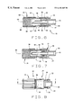
- FIG. 4 a is a side elevational view of the preferred embodiment of the adapter in an unactuated position according to the present invention
- FIG. 4 b is a side elevational view of an alternative embodiment of the adapter in an unactuated position according to the present invention.
- FIG. 5 is a top plan view of the preferred embodiment of the adapter in an unactuated position according to the present invention.
- FIG. 6 is a cross-section of the preferred embodiment of the adapter along line A—A of FIG. 4 a according to the present invention
- FIG. 7 is a cross-section of the preferred embodiment of the adapter along line B—B of FIG. 5 according to the present invention.
- FIG. 8 is a top plan view of the preferred embodiment of the adapter in an actuated position according to the present invention.
- FIG. 9 is a side elevational view of the preferred embodiment of the adapter in an actuated position according to the present invention.
- FIG. 10 is a cross-sectional view of the preferred embodiment of the adapter along line C—C of FIG. 8 according to the present invention.
- FIG. 11 is a cross-sectional view of the preferred embodiment of the adapter along line D—D of FIG. 9 according to the present invention.
- adapter 10 operates as a connector between a fluid container 88 and an administration tubing set 90 with the fluid container 88 including a cap 92 that has an orifice 96 and threading 98 disposed about the cap 92 .
- a foil 100 or other frangible membrane, seals off the orifice 96 of container 88 from fluid flow.
- the administration tubing set 90 includes tubing 94 which interconnects a tube arrangement (not shown) which is connected to a patient to the fluid container 88 via the adapter 10 of the present invention. As shown in FIG.
- the adapter 10 comprises a body member 12 slidably connected to a spike member 14 and rotatably connected to a locking collar 16 .
- adapter 10 further includes a rolling seal diaphragm 18 disposed within the body member 12 .
- the body member 12 comprises a hollow body portion 20 having opposed openings 25 , 27 which form a channel 31 therebetween with a pair of laterally opposed leg portions 26 which extend axially proximate the opening 27 .
- the preferred embodiment has a pair of leg portions 26 .
- Each leg portion 26 includes a tab 22 formed at the free end of each leg portion 26 .
- tabs 22 are bifurcated along the free end thereof.
- the body member 12 further includes an interior annular ridge 23 formed adjacent opening 27 and two pairs of opposed protrusions 28 longitudinally aligned and extending along the body portion 20 . Formed between each pair of protrusions 28 is a beveled portion 30 defining a ledge 32 . Further, body member 12 includes an exterior annular flange 34 formed proximate opening 25 . Alternatively, it should be appreciated that any suitable number of protrusions 28 may be utilized without departing from the teachings of the present invention.
- spike member 14 of adapter 10 comprises a spike body 42 defining two opposed pairs of longitudinal slots 44 which correspond to the two opposed pairs of protrusions 28 formed on body member 12 .
- Each slot 44 is sized and shaped to slidably receive a corresponding protrusion 28 when the spike member 14 is in the actuated position, as shall be discussed in greater detail below.
- spike member 14 further includes two axial openings 43 , as particularly shown in FIG. 3, which are sized and shaped to receive and retain a corresponding tab 22 of each leg portion 26 .
- any number of slots 44 and openings 43 may be utilized to interconnect the body member 12 to spike member 14 without departing from the teachings of the present invention.
- each pair of slots 44 define a retention section 46 which includes a retention edge 48 formed at a distal or free end of each section 46 .
- Each section 46 is positioned between a respective corresponding pair of protrusions 28 and is adapted to slide between each pair of protrusions 28 while traveling along the corresponding beveled surface 30 formed on the body member 12 .
- the section 46 is prevented from separating from body member 12 due to the engagement between retention edge 48 of spike member 14 and the ledge 32 formed on body member 12 as well as the relative action of tab 22 with spike body 42 , as shall be described with greater detail later.
- spike member 14 further includes an axial spike 52 outwardly extending from the spike body 42 defining opposed ends 36 , 38 which form a channel 40 therebetween.
- spike 52 includes a distal longitudinal slot 56 formed along a portion of spike 52 and that terminates at an angularly skewed end 54 .
- a shoulder portion 58 circumferentially disposed about the spike 52 which assists in forming a seal between the spike member 14 and diaphragm 18 as will be discussed in greater detail below.
- Spike body 42 further includes a proximal tube adapter 60 formed opposite spike 52 having an opening 61 aligned with spike 52 proximate end 36 and sized and shaped to be connected to administration tubing set 90 , as illustrated in FIG. 1 .
- spike 52 is disposed entirely within the adapter 10 as illustrated in FIG. 4 a .
- spike 52 extends beyond the collar 16 when adapter 10 is fully assembled.
- adapter 10 of the present invention also includes locking collar 16 comprising a body portion 62 with opposed openings 65 , 66 forming a channel 64 therebetween.
- Channel 64 includes an annular groove 67 formed proximate opening 65 and a threaded portion 68 formed proximate opening 66 .
- longitudinal grooves 70 are formed along the body portion 62 of the locking collar 16 to enhance the ability of the operator to grasp the locking collar 16 .
- one skilled in the art can best appreciate that a variety of other connective arrangements may be utilized without departing from the teachings of the present invention.
- one unique aspect of adapter 10 is that it includes rolling seal diaphragm 18 which forms and maintains a fluid-tight seal during operation of adapter 10 .
- diaphragm 18 comprises a body portion 72 which includes a pair of opposed openings 73 , 75 with a channel 77 formed therebetween.
- Diaphragm 18 further comprises an annular flange 74 disposed proximate opening 73 and circumferentially disposed about the body portion 72 , while an outer stepped portion 76 is formed proximate opening 75 .
- the diaphragm 18 also is provided with a rolling seal portion 80 which is attachable to, or integral with, opening 73 and located adjacent flange 74 of body member 72 .
- the rolling seal portion 80 includes an outer portion 82 and an inner portion 84 attached to, or integral with the outer portion 82 which is coaxially aligned and disposed within the outer portion 82 .
- Both the inner portion 84 and outer portion 82 are generally cylindrical in shape.
- Attached to, or integral with, the inner portion 84 is an inwardly stepped portion 86 which abuts the shoulder portion 58 of the spike 52 and forms a rolling seal between the spike 52 and the inwardly stepped portion 86 of diaphragm 18 as the spike 52 is forced axially forward to the engaged position during operation of adapter 10 .
- the inward portion 84 of rolling seal portion 80 rolls along the spike 52 which is sealingly engaged therealong due to the engagement between the shoulder portion 58 of spike 52 and the inwardly stepped portion 86 of diaphragm 18 .
- the outer portion 82 of rolling seal portion 80 rolls inwardly allowing the inwardly stepped portion 86 to maintain a sealing engagement between moving spike 52 and diaphragm 18 .
- adapter 10 is assembled during manufacturing by first inserting diaphragm 18 within body member 12 by inserting diaphragm 18 through opening 25 . Diaphragm 18 is then aligned within channel 31 such that the flange 74 crowns the ridge 23 , while the outer stepped portion 76 abuts the opening 25 of body member 12 so that rolling seal portion 80 extends outwardly from body portion 20 . Next, spike member 14 is connected to body member 12 and aligned such that each corresponding protrusion 28 is slidably received within each corresponding slot 44 of spike body 42 .
- Spike member 14 is then axially depressed onto body member 12 until tabs 22 are passed through the corresponding openings 43 and retention edge 48 are disposed adjacent the beveled portion 30 .
- the collar 16 is then engaged about the body member 12 so that annular flange 34 of body member 12 is engagingly received within the annular groove 66 of locking collar 16 .
- spike member 14 may be biased between two positions: an actuated position, wherein spike member 14 abuts locking collar 16 , as illustrated in FIGS. 10 and 11, and an unactuated position, wherein spike member 14 abuts tabs 22 of the body member 12 , as seen in FIGS. 4 a and 5 .
- the adapter 10 of the present invention is uniquely configured to interconnect the fluid container 88 to the administration tubing set 90 .
- the adapter 10 is connected to the fluid container 88 by screwing the threaded portion 68 of the locking collar 16 onto the threaded portion 98 of the cap 92 while the spike 52 is isolated within the collar 16 to prevent undesirable contact and contamination of the axial spike 52 .
- the operator then connects tube 94 which has been bonded to tube adapter 60 to the patient's tube arrangement.
- the user will grasp spike member 14 preferably between the user's thumb and forefinger (not shown) and urge the spike member 14 forwardly as illustrated in FIGS. 8 and 9, through collar 16 .
- the forward axial motion of spike 52 is restrained at one point by the abutment of retention edge 48 of spike member 14 with collar 16 .
- the inward portion 84 of the rolling seal portion 80 rolls along the spike 52 which is sealingly engaged therealong due to the engagement between the shoulder portion 58 of spike 52 and the inwardly stepped portion 86 of diaphragm 18 .
- outer portion 82 of the rolling seal portion 80 rolls inwardly allowing the inwardly stepped portion 86 to maintain a sealing engagement between spike 52 and diaphragm 18 .
- body member 12 , the spike member 14 , and the locking collar 16 are constructed from a substantially rigid medical-grade material, while diaphragm 18 is constructed from a substantially flexible elastic material.
- body member 12 , the spike member 14 , and the locking collar 16 are constructed from a thermoplastic, such as ABS and the like, while diaphragm 18 is constructed from a thermoplastic, thermosetting rubber or other similar elastomeric material.
Abstract
Description
Claims (9)
Priority Applications (9)
| Application Number | Priority Date | Filing Date | Title |
|---|---|---|---|
| US09/387,647 US6183465B1 (en) | 1999-09-01 | 1999-09-01 | Adapter for a feeding system |
| CA002383525A CA2383525C (en) | 1999-09-01 | 2000-08-30 | Adapter for a feeding system |
| JP2001520178A JP4338344B2 (en) | 1999-09-01 | 2000-08-30 | Nutrition system adapter |
| MXPA02002205A MXPA02002205A (en) | 1999-09-01 | 2000-08-30 | Adapter for a feeding system. |
| BR0015045-2A BR0015045A (en) | 1999-09-01 | 2000-08-30 | Adapter for a feeding system and method for establishing connection between a nutrition container and a set of administration piping |
| PCT/US2000/024031 WO2001015769A1 (en) | 1999-09-01 | 2000-08-30 | Adapter for a feeding system |
| AU71000/00A AU774554B2 (en) | 1999-09-01 | 2000-08-30 | Adapter for a feeding system |
| EP00959732A EP1207935A1 (en) | 1999-09-01 | 2000-08-30 | Adapter for a feeding system |
| JP2009009943A JP4759063B2 (en) | 1999-09-01 | 2009-01-20 | adapter |
Applications Claiming Priority (1)
| Application Number | Priority Date | Filing Date | Title |
|---|---|---|---|
| US09/387,647 US6183465B1 (en) | 1999-09-01 | 1999-09-01 | Adapter for a feeding system |
Publications (1)
| Publication Number | Publication Date |
|---|---|
| US6183465B1 true US6183465B1 (en) | 2001-02-06 |
Family
ID=23530793
Family Applications (1)
| Application Number | Title | Priority Date | Filing Date |
|---|---|---|---|
| US09/387,647 Expired - Lifetime US6183465B1 (en) | 1999-09-01 | 1999-09-01 | Adapter for a feeding system |
Country Status (8)
| Country | Link |
|---|---|
| US (1) | US6183465B1 (en) |
| EP (1) | EP1207935A1 (en) |
| JP (2) | JP4338344B2 (en) |
| AU (1) | AU774554B2 (en) |
| BR (1) | BR0015045A (en) |
| CA (1) | CA2383525C (en) |
| MX (1) | MXPA02002205A (en) |
| WO (1) | WO2001015769A1 (en) |
Cited By (31)
| Publication number | Priority date | Publication date | Assignee | Title |
|---|---|---|---|---|
| US20030153865A1 (en) * | 2002-02-11 | 2003-08-14 | Brian Connell | Dialysis connector and cap having an integral disinfectant |
| US20030225393A1 (en) * | 2002-05-31 | 2003-12-04 | Kimberly-Clark Worldwide, Inc. | Low profile transpyloric jejunostomy system and method to enable |
| US20030225369A1 (en) * | 2002-05-31 | 2003-12-04 | Kimberly-Clark Worldwide, Inc. | Low profile transpyloric jejunostomy system |
| US20040097842A1 (en) * | 2002-11-15 | 2004-05-20 | Advanced Respiratory, Inc. | Oscillatory chest wall compression device with improved air pulse generator with improved user interface |
| US20040181999A1 (en) * | 2001-07-16 | 2004-09-23 | Maurice Amsellem | Individual plant watering device |
| US20040211484A1 (en) * | 2002-08-22 | 2004-10-28 | Sherwood Services, Ag. | Sliding seal adapter for a feeding system |
| US20050197646A1 (en) * | 2002-02-11 | 2005-09-08 | Brian Connell | Dialysis connector with retention and feedback features |
| US20050253390A1 (en) * | 2004-05-12 | 2005-11-17 | Blazek Larry M | Medical tubing quick disconnect apparatus |
| US20060032119A1 (en) * | 2001-07-16 | 2006-02-16 | Maurice Amsellem | Individual plant watering device |
| US20060229590A1 (en) * | 2003-03-03 | 2006-10-12 | Pierre Roy | Uniform feed connector for devices for the delivery of active principles |
| US20070112323A1 (en) * | 2005-10-20 | 2007-05-17 | Sherwood Services Ag | Enteral Feeding Set |
| US7232419B2 (en) | 2002-02-11 | 2007-06-19 | Baxter International Inc. | Enclosure with cam action snap release |
| US20070289668A1 (en) * | 2006-06-06 | 2007-12-20 | Cardinal Health 414, Inc. | Method and apparatus for the handling of a hazardous fluid |
| US7611502B2 (en) | 2005-10-20 | 2009-11-03 | Covidien Ag | Connector for enteral fluid delivery set |
| US20090275881A1 (en) * | 2008-05-02 | 2009-11-05 | Baxter International Inc. | Optimizing therapy outcomes for peritoneal dialysis |
| US20100130919A1 (en) * | 2008-11-21 | 2010-05-27 | Baxter International Inc. | Systems and methods for removing air from the patient's peritoneal cavity |
| US20100130918A1 (en) * | 2008-11-21 | 2010-05-27 | Baxter International Inc. | Systems and methods for removing air from supply containers and associated fill tubing |
| US20100198138A1 (en) * | 2009-01-30 | 2010-08-05 | Baxter International Inc. | Transfer sets for therapy optimization |
| US20100286664A1 (en) * | 2009-05-08 | 2010-11-11 | Abbott Cardiovascular Systems, Inc. | Catheter push device |
| US20100308056A1 (en) * | 2007-05-24 | 2010-12-09 | Torsten Brandenburger | Closure cap for a container for receiving liquids and in particular an enteral nutrient solution, and container having such a closure cap |
| US20100331787A1 (en) * | 2009-06-30 | 2010-12-30 | Tyco Healthcare Group Lp | Female adaptor for feeding line |
| US20110118676A1 (en) * | 2009-05-11 | 2011-05-19 | Kropczynski Jr John J | Enteral Connectors and Systems |
| US20120041426A1 (en) * | 2010-08-10 | 2012-02-16 | Medical Components, Inc. | Collet Lock |
| US8882700B2 (en) | 2008-05-02 | 2014-11-11 | Baxter International Inc. | Smart patient transfer set for peritoneal dialysis |
| CN104998318A (en) * | 2014-04-18 | 2015-10-28 | 美国昊朗国际公司 | Vein treatment device |
| US20160051135A1 (en) * | 2012-09-13 | 2016-02-25 | Emmy Medical, Llc. | 4-way cystoscopy catheter |
| US20170368325A1 (en) * | 2015-03-11 | 2017-12-28 | Terumo Kabushiki Kaisha | Connector and medical device set |
| US20190076319A1 (en) * | 2016-03-02 | 2019-03-14 | Jms Co., Ltd. | Puncture needle connector and connecting tube |
| USD908865S1 (en) | 2018-08-17 | 2021-01-26 | Emmy Medical, Llc | Catheter |
| US11147958B2 (en) * | 2013-11-06 | 2021-10-19 | Becton Dickinson and Company Limited | System for closed transfer of fluids having connector |
| US11376409B2 (en) | 2014-09-08 | 2022-07-05 | Avent, Inc. | Hub component for vented connector |
Families Citing this family (6)
| Publication number | Priority date | Publication date | Assignee | Title |
|---|---|---|---|---|
| US8439859B2 (en) | 2007-10-08 | 2013-05-14 | Ais Gmbh Aachen Innovative Solutions | Catheter device |
| US8489190B2 (en) | 2007-10-08 | 2013-07-16 | Ais Gmbh Aachen Innovative Solutions | Catheter device |
| US9925026B2 (en) * | 2014-07-21 | 2018-03-27 | Kerr Corporation | Adapters, tips, and dental assemblies |
| JP2017209149A (en) * | 2016-05-23 | 2017-11-30 | ニプロ株式会社 | Medical connector |
| EP3818007A4 (en) | 2018-07-06 | 2022-04-20 | Liqui-Box Corporation | Dispensing probe for dispensing flowable material |
| JP7242221B2 (en) * | 2018-09-06 | 2023-03-20 | 矢崎エナジーシステム株式会社 | Outlet nozzle and drinking water supply |
Citations (14)
| Publication number | Priority date | Publication date | Assignee | Title |
|---|---|---|---|---|
| US4567999A (en) | 1981-05-07 | 1986-02-04 | International Nutritional Research Institute Ab | Self-adhesive connecting device |
| US4888008A (en) | 1987-03-03 | 1989-12-19 | Sherwood Medical Company | Vented spike connection component |
| US5041105A (en) | 1987-03-03 | 1991-08-20 | Sherwood Medical Company | Vented spike connection component |
| US5053015A (en) * | 1989-08-30 | 1991-10-01 | The Kendall Company | Locking catheter adapter |
| US5209740A (en) * | 1991-11-22 | 1993-05-11 | Abbott Laboratories | Catheter adapter having retention notches |
| US5215538A (en) * | 1992-02-05 | 1993-06-01 | Abbott Laboratories | Connector-activated in-line valve |
| US5226898A (en) * | 1989-08-30 | 1993-07-13 | The Kendall Company | Catheter adapter with strain relief |
| US5303751A (en) | 1991-10-04 | 1994-04-19 | Fresenius Ag | Spiked bag packaging system |
| US5456676A (en) * | 1994-02-18 | 1995-10-10 | Merit Medical Systems, Inc. | Rotatable bubble-free connector |
| US5607392A (en) * | 1995-01-13 | 1997-03-04 | Ryder International Corporation | Fixed needle connector for IV assembly and method of assembling |
| US5624414A (en) | 1992-02-18 | 1997-04-29 | St. Francis Research Institute | Needleless straight infusion port |
| US5782808A (en) | 1994-02-14 | 1998-07-21 | Fresenius Usa, Inc. | Antibacterial medical tubing connector |
| US5830195A (en) * | 1994-02-17 | 1998-11-03 | Clinical Product Development Limited | Couplings for medical cannulae |
| US5976115A (en) * | 1997-10-09 | 1999-11-02 | B. Braun Medical, Inc. | Blunt cannula spike adapter assembly |
Family Cites Families (7)
| Publication number | Priority date | Publication date | Assignee | Title |
|---|---|---|---|---|
| US4187846A (en) * | 1978-06-22 | 1980-02-12 | Union Carbide Corporation | Sterile connectors |
| US4508367A (en) * | 1979-01-09 | 1985-04-02 | Oreopoulos Dimitrios G | Connector |
| US4607868A (en) * | 1983-11-30 | 1986-08-26 | Baxter Travenol Laboratories, Inc. | Universal connector |
| US5113571A (en) * | 1990-01-29 | 1992-05-19 | Manska Wayne E | Method of manufacturing a connector for medical devices |
| US5088984A (en) * | 1990-10-03 | 1992-02-18 | Tri-State Hospital Supply Corporation | Medical connector |
| CA2211629A1 (en) * | 1996-09-17 | 1998-03-17 | Bernard Sams | Vial connector assembly for a medicament container |
| US5954104A (en) * | 1997-02-28 | 1999-09-21 | Abbott Laboratories | Container cap assembly having an enclosed penetrator |
-
1999
- 1999-09-01 US US09/387,647 patent/US6183465B1/en not_active Expired - Lifetime
-
2000
- 2000-08-30 AU AU71000/00A patent/AU774554B2/en not_active Expired
- 2000-08-30 JP JP2001520178A patent/JP4338344B2/en not_active Expired - Fee Related
- 2000-08-30 BR BR0015045-2A patent/BR0015045A/en not_active Application Discontinuation
- 2000-08-30 CA CA002383525A patent/CA2383525C/en not_active Expired - Lifetime
- 2000-08-30 EP EP00959732A patent/EP1207935A1/en not_active Withdrawn
- 2000-08-30 MX MXPA02002205A patent/MXPA02002205A/en active IP Right Grant
- 2000-08-30 WO PCT/US2000/024031 patent/WO2001015769A1/en active Search and Examination
-
2009
- 2009-01-20 JP JP2009009943A patent/JP4759063B2/en not_active Expired - Fee Related
Patent Citations (14)
| Publication number | Priority date | Publication date | Assignee | Title |
|---|---|---|---|---|
| US4567999A (en) | 1981-05-07 | 1986-02-04 | International Nutritional Research Institute Ab | Self-adhesive connecting device |
| US4888008A (en) | 1987-03-03 | 1989-12-19 | Sherwood Medical Company | Vented spike connection component |
| US5041105A (en) | 1987-03-03 | 1991-08-20 | Sherwood Medical Company | Vented spike connection component |
| US5226898A (en) * | 1989-08-30 | 1993-07-13 | The Kendall Company | Catheter adapter with strain relief |
| US5053015A (en) * | 1989-08-30 | 1991-10-01 | The Kendall Company | Locking catheter adapter |
| US5303751A (en) | 1991-10-04 | 1994-04-19 | Fresenius Ag | Spiked bag packaging system |
| US5209740A (en) * | 1991-11-22 | 1993-05-11 | Abbott Laboratories | Catheter adapter having retention notches |
| US5215538A (en) * | 1992-02-05 | 1993-06-01 | Abbott Laboratories | Connector-activated in-line valve |
| US5624414A (en) | 1992-02-18 | 1997-04-29 | St. Francis Research Institute | Needleless straight infusion port |
| US5782808A (en) | 1994-02-14 | 1998-07-21 | Fresenius Usa, Inc. | Antibacterial medical tubing connector |
| US5830195A (en) * | 1994-02-17 | 1998-11-03 | Clinical Product Development Limited | Couplings for medical cannulae |
| US5456676A (en) * | 1994-02-18 | 1995-10-10 | Merit Medical Systems, Inc. | Rotatable bubble-free connector |
| US5607392A (en) * | 1995-01-13 | 1997-03-04 | Ryder International Corporation | Fixed needle connector for IV assembly and method of assembling |
| US5976115A (en) * | 1997-10-09 | 1999-11-02 | B. Braun Medical, Inc. | Blunt cannula spike adapter assembly |
Cited By (63)
| Publication number | Priority date | Publication date | Assignee | Title |
|---|---|---|---|---|
| US20060032119A1 (en) * | 2001-07-16 | 2006-02-16 | Maurice Amsellem | Individual plant watering device |
| US7845110B2 (en) | 2001-07-16 | 2010-12-07 | Aquasolo Systems | Individual plant watering device |
| US20100180496A1 (en) * | 2001-07-16 | 2010-07-22 | Aquasolo Systems | Individual plant watering device |
| US7685766B2 (en) | 2001-07-16 | 2010-03-30 | Aquasolo Systems | Individual plant watering device |
| US20040181999A1 (en) * | 2001-07-16 | 2004-09-23 | Maurice Amsellem | Individual plant watering device |
| US7708714B2 (en) | 2002-02-11 | 2010-05-04 | Baxter International Inc. | Dialysis connector with retention and feedback features |
| US7198611B2 (en) | 2002-02-11 | 2007-04-03 | Baxter International Inc. | Dialysis connector and cap having an integral disinfectant |
| US20050197646A1 (en) * | 2002-02-11 | 2005-09-08 | Brian Connell | Dialysis connector with retention and feedback features |
| US7232419B2 (en) | 2002-02-11 | 2007-06-19 | Baxter International Inc. | Enclosure with cam action snap release |
| US20030153865A1 (en) * | 2002-02-11 | 2003-08-14 | Brian Connell | Dialysis connector and cap having an integral disinfectant |
| US20070106205A1 (en) * | 2002-02-11 | 2007-05-10 | Baxter International Inc. | Dialysis connector and cap having an integral disinfectant |
| US20030225369A1 (en) * | 2002-05-31 | 2003-12-04 | Kimberly-Clark Worldwide, Inc. | Low profile transpyloric jejunostomy system |
| US20030225393A1 (en) * | 2002-05-31 | 2003-12-04 | Kimberly-Clark Worldwide, Inc. | Low profile transpyloric jejunostomy system and method to enable |
| US7080672B2 (en) | 2002-08-22 | 2006-07-25 | Sherwood Services Ag | Sliding seal adapter for a feeding system |
| US20040211484A1 (en) * | 2002-08-22 | 2004-10-28 | Sherwood Services, Ag. | Sliding seal adapter for a feeding system |
| US7582065B2 (en) | 2002-11-15 | 2009-09-01 | Hill-Rom Services, Inc. | Air pulse generator with multiple operating modes |
| US20060009718A1 (en) * | 2002-11-15 | 2006-01-12 | Van Brunt Nicholas P | Air pulse generator with multiple operating modes |
| US20040097842A1 (en) * | 2002-11-15 | 2004-05-20 | Advanced Respiratory, Inc. | Oscillatory chest wall compression device with improved air pulse generator with improved user interface |
| US20060229590A1 (en) * | 2003-03-03 | 2006-10-12 | Pierre Roy | Uniform feed connector for devices for the delivery of active principles |
| US7771403B2 (en) * | 2003-03-03 | 2010-08-10 | Eyegate Pharma S.A. | Uniform feed connector for devices for the delivery of active principles |
| US7390028B2 (en) | 2004-05-12 | 2008-06-24 | Blazek Larry M | Medical tubing quick disconnect apparatus |
| US20050253390A1 (en) * | 2004-05-12 | 2005-11-17 | Blazek Larry M | Medical tubing quick disconnect apparatus |
| WO2006083333A1 (en) * | 2005-01-28 | 2006-08-10 | Baxter International Inc. | Dialysis connector with retention and feedback features |
| US7611502B2 (en) | 2005-10-20 | 2009-11-03 | Covidien Ag | Connector for enteral fluid delivery set |
| US7896859B2 (en) | 2005-10-20 | 2011-03-01 | Tyco Healthcare Group Lp | Enteral feeding set |
| US8357136B2 (en) | 2005-10-20 | 2013-01-22 | Covidien Lp | Enteral feeding set |
| US20070112323A1 (en) * | 2005-10-20 | 2007-05-17 | Sherwood Services Ag | Enteral Feeding Set |
| US7703486B2 (en) * | 2006-06-06 | 2010-04-27 | Cardinal Health 414, Inc. | Method and apparatus for the handling of a radiopharmaceutical fluid |
| US8667997B2 (en) | 2006-06-06 | 2014-03-11 | Cardinal Health 414, Llc | Method and apparatus for the handling of a hazardous fluid |
| US20100174182A1 (en) * | 2006-06-06 | 2010-07-08 | Cardinal Health 414, Inc. | Method and apparatus for the handling of a hazardous fluid |
| US20070289668A1 (en) * | 2006-06-06 | 2007-12-20 | Cardinal Health 414, Inc. | Method and apparatus for the handling of a hazardous fluid |
| US8156971B2 (en) * | 2006-06-06 | 2012-04-17 | Cardinal Health 414, Llc. | Method and apparatus for the handling of a hazardous fluid |
| US9150336B2 (en) * | 2007-05-24 | 2015-10-06 | Fresenius Kabi Deutschland Gmbh | Closure cap for a container for receiving liquids and in particular an enteral nutrient solution, and container having such a closure cap |
| US20100308056A1 (en) * | 2007-05-24 | 2010-12-09 | Torsten Brandenburger | Closure cap for a container for receiving liquids and in particular an enteral nutrient solution, and container having such a closure cap |
| US8882700B2 (en) | 2008-05-02 | 2014-11-11 | Baxter International Inc. | Smart patient transfer set for peritoneal dialysis |
| US9348975B2 (en) | 2008-05-02 | 2016-05-24 | Baxter International Inc. | Optimizing therapy outcomes for peritoneal dialysis |
| US20090275881A1 (en) * | 2008-05-02 | 2009-11-05 | Baxter International Inc. | Optimizing therapy outcomes for peritoneal dialysis |
| US9555180B2 (en) | 2008-11-21 | 2017-01-31 | Baxter International Inc. | Systems and methods for removing air from the patient's peritoneal cavity |
| US20100130919A1 (en) * | 2008-11-21 | 2010-05-27 | Baxter International Inc. | Systems and methods for removing air from the patient's peritoneal cavity |
| US20100130918A1 (en) * | 2008-11-21 | 2010-05-27 | Baxter International Inc. | Systems and methods for removing air from supply containers and associated fill tubing |
| US8377012B2 (en) | 2009-01-30 | 2013-02-19 | Baxter International Inc. | Transfer sets for therapy optimization |
| US20100198138A1 (en) * | 2009-01-30 | 2010-08-05 | Baxter International Inc. | Transfer sets for therapy optimization |
| US8636706B2 (en) | 2009-01-30 | 2014-01-28 | Baxter International Inc. | Transfer sets for therapy optimization |
| US20100286664A1 (en) * | 2009-05-08 | 2010-11-11 | Abbott Cardiovascular Systems, Inc. | Catheter push device |
| US8628509B2 (en) | 2009-05-11 | 2014-01-14 | Abbott Laboratories | Enteral connectors and systems |
| US20110118676A1 (en) * | 2009-05-11 | 2011-05-19 | Kropczynski Jr John J | Enteral Connectors and Systems |
| US7955317B2 (en) * | 2009-06-30 | 2011-06-07 | Tyco Healthcare Group Lp | Female adaptor for feeding line |
| US20100331787A1 (en) * | 2009-06-30 | 2010-12-30 | Tyco Healthcare Group Lp | Female adaptor for feeding line |
| US20120041426A1 (en) * | 2010-08-10 | 2012-02-16 | Medical Components, Inc. | Collet Lock |
| US9149621B2 (en) * | 2010-08-10 | 2015-10-06 | Medical Components, Inc. | Collet lock |
| US20160051135A1 (en) * | 2012-09-13 | 2016-02-25 | Emmy Medical, Llc. | 4-way cystoscopy catheter |
| US10376137B2 (en) * | 2012-09-13 | 2019-08-13 | Emmy Medical, Llc | Indwelling bladder catheter |
| US11147958B2 (en) * | 2013-11-06 | 2021-10-19 | Becton Dickinson and Company Limited | System for closed transfer of fluids having connector |
| CN104998318A (en) * | 2014-04-18 | 2015-10-28 | 美国昊朗国际公司 | Vein treatment device |
| CN104998318B (en) * | 2014-04-18 | 2018-08-03 | 广东海恺普新型医药包装材料有限公司 | Vein treatment device |
| CN108853638A (en) * | 2014-04-18 | 2018-11-23 | 广东海恺普新型医药包装材料有限公司 | Vein treatment device |
| US11376409B2 (en) | 2014-09-08 | 2022-07-05 | Avent, Inc. | Hub component for vented connector |
| US20170368325A1 (en) * | 2015-03-11 | 2017-12-28 | Terumo Kabushiki Kaisha | Connector and medical device set |
| US10716929B2 (en) * | 2015-03-11 | 2020-07-21 | Terumo Kabushiki Kaisha | Connector and medical device set |
| US20190076319A1 (en) * | 2016-03-02 | 2019-03-14 | Jms Co., Ltd. | Puncture needle connector and connecting tube |
| US11744773B2 (en) * | 2016-03-02 | 2023-09-05 | Jms Co., Ltd. | Puncture needle connector and connecting tube |
| USD908865S1 (en) | 2018-08-17 | 2021-01-26 | Emmy Medical, Llc | Catheter |
| USD935013S1 (en) | 2018-08-17 | 2021-11-02 | Emmy Medical, Llc | Catheter |
Also Published As
| Publication number | Publication date |
|---|---|
| CA2383525C (en) | 2009-04-07 |
| EP1207935A1 (en) | 2002-05-29 |
| MXPA02002205A (en) | 2003-04-10 |
| JP4338344B2 (en) | 2009-10-07 |
| CA2383525A1 (en) | 2001-03-08 |
| BR0015045A (en) | 2002-07-02 |
| JP2009136693A (en) | 2009-06-25 |
| WO2001015769A1 (en) | 2001-03-08 |
| AU7100000A (en) | 2001-03-26 |
| JP2003528651A (en) | 2003-09-30 |
| JP4759063B2 (en) | 2011-08-31 |
| AU774554B2 (en) | 2004-07-01 |
Similar Documents
| Publication | Publication Date | Title |
|---|---|---|
| US6183465B1 (en) | Adapter for a feeding system | |
| US7080672B2 (en) | Sliding seal adapter for a feeding system | |
| US6585229B2 (en) | Medical nozzle securing apparatus | |
| US5868433A (en) | Connector assembly | |
| US6341802B1 (en) | Fluid delivery systems and methods and assemblies for making connections | |
| US4998927A (en) | Connector | |
| EP0781151B1 (en) | Valved intravenous fluid line infusion device | |
| US9814652B2 (en) | Universal needlefree bag access device | |
| WO2004103256B1 (en) | Improved transfer set | |
| US5685842A (en) | Drug delivery system and method | |
| WO2010052517A1 (en) | Improved drug container | |
| EP0820777B1 (en) | System for the administration of substances by infusion | |
| AU731082B2 (en) | Connector assembly |
Legal Events
| Date | Code | Title | Description |
|---|---|---|---|
| AS | Assignment |
Owner name: SHERWOOD SERVICES, A.G., SWITZERLAND Free format text: ASSIGNMENT OF ASSIGNORS INTEREST;ASSIGNORS:MEIER, KEVIN C.;FOURNIE, GLENN;RANFORD, ALAN;AND OTHERS;REEL/FRAME:010399/0800;SIGNING DATES FROM 19991011 TO 19991115 |
|
| STCF | Information on status: patent grant |
Free format text: PATENTED CASE |
|
| AS | Assignment |
Owner name: SHERWOOD SERVICES, AG, SWITZERLAND Free format text: CORRECTIVE ASSIGNMENT TO CORRECT THE STATE OF INCORPORATION FOR THE RECEIVING PARTY. DOCUMENT PREVIOUSLY RECORDED AT REEL 010399 FRAME 0800;ASSIGNORS:MEIER, KEVIN C.;FOURNIE, GLENN G.;RANFORD, ALAN;AND OTHERS;REEL/FRAME:013656/0784;SIGNING DATES FROM 19991011 TO 19991115 |
|
| FEPP | Fee payment procedure |
Free format text: PAYOR NUMBER ASSIGNED (ORIGINAL EVENT CODE: ASPN); ENTITY STATUS OF PATENT OWNER: LARGE ENTITY |
|
| FPAY | Fee payment |
Year of fee payment: 4 |
|
| SULP | Surcharge for late payment | ||
| FPAY | Fee payment |
Year of fee payment: 8 |
|
| AS | Assignment |
Owner name: COVIDIEN AG, SWITZERLAND Free format text: CHANGE OF NAME;ASSIGNOR:SHERWOOD SERVICES AG;REEL/FRAME:021371/0142 Effective date: 20070309 |
|
| FPAY | Fee payment |
Year of fee payment: 12 |
|
| AS | Assignment |
Owner name: CARDINAL HEALTH IRELAND UNLIMITED COMPANY, IRELAND Free format text: ASSIGNMENT OF ASSIGNORS INTEREST;ASSIGNORS:COVIDIEN AG;COVIDIEN FINANCE INTERNATIONAL GMBH;REEL/FRAME:044763/0234 Effective date: 20170729 |