US6193912B1 - Near infrared-absorbing electrochromic compounds and devices comprising same - Google Patents
Near infrared-absorbing electrochromic compounds and devices comprising same Download PDFInfo
- Publication number
- US6193912B1 US6193912B1 US09/034,531 US3453198A US6193912B1 US 6193912 B1 US6193912 B1 US 6193912B1 US 3453198 A US3453198 A US 3453198A US 6193912 B1 US6193912 B1 US 6193912B1
- Authority
- US
- United States
- Prior art keywords
- medium
- electrochromic
- carbon atoms
- alkyl
- compound
- Prior art date
- Legal status (The legal status is an assumption and is not a legal conclusion. Google has not performed a legal analysis and makes no representation as to the accuracy of the status listed.)
- Expired - Lifetime
Links
- NIHPWCXNSGILGS-UHFFFAOYSA-N CC1=CC=C2C(=C1)CC1=C(C=CC(C)=C1)N2C Chemical compound CC1=CC=C2C(=C1)CC1=C(C=CC(C)=C1)N2C NIHPWCXNSGILGS-UHFFFAOYSA-N 0.000 description 4
- 0 *.*=[V].*I.C1=C2CCCN3CCCC(=C23)C=C1C1=C/C2=C3\C(=C/1)CCCN3CCC2.CCCCN1C2=CC3=C(C=C2N(CCCC)C2=C1C=CC(C(F)(F)F)=C2)N(CCCC)C1=CC=C(C(F)(F)F)C=C1N3CCCC.CCCCOC1=C2SC3=C(C=CC=C3)N(C)C2=C(OCCCC)C2=C1N(C)C1=CC=CC=C1S2.CCCN1C2=CC=CC=C2OC2=CC3=C(C=C21)OC1=CC=CC=C1N3CCC.CCN(CC)C1=CC2=C(C=C1)N(C)C1=CC=C(N(C)C)C=C1N2C.CCN1C2=CC=C(N(C)C)C=C2C2=C1C=CC(N(C)C)=C2.CN(C)C1=CC2=C(C=C1)N(C)C1=CC3=C(C=CC=C3)C=C1O2.COC1=CC=C(N(C2=CC=C(OC)C=C2)C2=CC=C(OC)C=C2)C=C1.I[V](I)I Chemical compound *.*=[V].*I.C1=C2CCCN3CCCC(=C23)C=C1C1=C/C2=C3\C(=C/1)CCCN3CCC2.CCCCN1C2=CC3=C(C=C2N(CCCC)C2=C1C=CC(C(F)(F)F)=C2)N(CCCC)C1=CC=C(C(F)(F)F)C=C1N3CCCC.CCCCOC1=C2SC3=C(C=CC=C3)N(C)C2=C(OCCCC)C2=C1N(C)C1=CC=CC=C1S2.CCCN1C2=CC=CC=C2OC2=CC3=C(C=C21)OC1=CC=CC=C1N3CCC.CCN(CC)C1=CC2=C(C=C1)N(C)C1=CC=C(N(C)C)C=C1N2C.CCN1C2=CC=C(N(C)C)C=C2C2=C1C=CC(N(C)C)=C2.CN(C)C1=CC2=C(C=C1)N(C)C1=CC3=C(C=CC=C3)C=C1O2.COC1=CC=C(N(C2=CC=C(OC)C=C2)C2=CC=C(OC)C=C2)C=C1.I[V](I)I 0.000 description 3
- DPMXDADJTJRXKN-UHFFFAOYSA-N CC1=CC=C2C(=C1)N(C)C1=C(C=C3C(=C1)CC1=C(C=CC=C1)N3C)N2C Chemical compound CC1=CC=C2C(=C1)N(C)C1=C(C=C3C(=C1)CC1=C(C=CC=C1)N3C)N2C DPMXDADJTJRXKN-UHFFFAOYSA-N 0.000 description 2
- BREAIYHMZMBERM-UHFFFAOYSA-N CN(C)C1=CC=C(N(C2=CC=C(N(C)C)C=C2)C2=CC=C(N(C)C)C=C2)C=C1 Chemical compound CN(C)C1=CC=C(N(C2=CC=C(N(C)C)C=C2)C2=CC=C(N(C)C)C=C2)C=C1 BREAIYHMZMBERM-UHFFFAOYSA-N 0.000 description 2
- ORLARJRBXRSOKV-YFFQWUJJSA-H *.C1=C2CCCN3CCCC(=C23)C=C1C1=C/C2=C3\C(=C/1)CCCN3CCC2.CCCCOC1=C2SC3=CC=CC=C3N(C)C2=C(OCCCC)C2=C1N(C)C1=CC=CC=C1S2.CCCN1C2=CC3=C(C=C2OC2=C1C=CC=C2)N(CCC)C1=CC=CC=C1O3.CCN1C2=CC=C(N(C)C)C=C2C2=C1C=CC(N(C)C)=C2.CCOC1=CC2=C(C=C1)N(CC)/C(=N\N=C1/SC3=CC(C)=CC=C3N1CC)S2.CN(C)C1=CC2=C(C=C1)N(C)C1=C3C=CC=CC3=CC=C1O2.COC1=CC=C(N(C2=CC=C(OC)C=C2)C2=CC=C(N(C3=CC=C(N(C)C)C=C3)C3=CC=C(N(C)C)C=C3)C=C2)C=C1.COC1=CC=C2C(=C1)SC1=C(C=CC(N(C)C)=C1)N2C.I[V](I)I.I[V]I.[V].[V]I Chemical compound *.C1=C2CCCN3CCCC(=C23)C=C1C1=C/C2=C3\C(=C/1)CCCN3CCC2.CCCCOC1=C2SC3=CC=CC=C3N(C)C2=C(OCCCC)C2=C1N(C)C1=CC=CC=C1S2.CCCN1C2=CC3=C(C=C2OC2=C1C=CC=C2)N(CCC)C1=CC=CC=C1O3.CCN1C2=CC=C(N(C)C)C=C2C2=C1C=CC(N(C)C)=C2.CCOC1=CC2=C(C=C1)N(CC)/C(=N\N=C1/SC3=CC(C)=CC=C3N1CC)S2.CN(C)C1=CC2=C(C=C1)N(C)C1=C3C=CC=CC3=CC=C1O2.COC1=CC=C(N(C2=CC=C(OC)C=C2)C2=CC=C(N(C3=CC=C(N(C)C)C=C3)C3=CC=C(N(C)C)C=C3)C=C2)C=C1.COC1=CC=C2C(=C1)SC1=C(C=CC(N(C)C)=C1)N2C.I[V](I)I.I[V]I.[V].[V]I ORLARJRBXRSOKV-YFFQWUJJSA-H 0.000 description 1
- NIPMCMVWJCEULL-UHFFFAOYSA-H *.CCCCN1C2=CC3=C(C=C2N(CCCC)C2=C1C=CC(C(F)(F)F)=C2)N(CCCC)C1=CC=C(C(F)(F)F)C=C1N3CCCC.CCCCOC1=C2SC3=C(C=CC=C3)N(C)C2=C(OCCCC)C2=C1N(C)C1=CC=CC=C1S2.CCCN1C2=CC=CC=C2OC2=CC3=C(C=C21)OC1=CC=CC=C1N3CCC.CCN(CC)C1=CC2=C(C=C1)N(C)C1=CC=C(N(C)C)C=C1N2C.CCN1C2=CC=C(N(C)C)C=C2C2=C1C=CC(N(C)C)=C2.CN(C)C1=CC2=C(C=C1)N(C)C1=C3C=CC=CC3=CC=C1O2.COC1=CC=C(N(C2=CC=C(OC)C=C2)C2=CC=C(N(C3=CC=C(OC)C=C3)C3=CC=C(OC)C=C3)C=C2)C=C1.COC1=CC=C2C(=C1)SC1=C(C=CC(N(C)C)=C1)N2C.I[V](I)I.I[V]I.[V].[V]I Chemical compound *.CCCCN1C2=CC3=C(C=C2N(CCCC)C2=C1C=CC(C(F)(F)F)=C2)N(CCCC)C1=CC=C(C(F)(F)F)C=C1N3CCCC.CCCCOC1=C2SC3=C(C=CC=C3)N(C)C2=C(OCCCC)C2=C1N(C)C1=CC=CC=C1S2.CCCN1C2=CC=CC=C2OC2=CC3=C(C=C21)OC1=CC=CC=C1N3CCC.CCN(CC)C1=CC2=C(C=C1)N(C)C1=CC=C(N(C)C)C=C1N2C.CCN1C2=CC=C(N(C)C)C=C2C2=C1C=CC(N(C)C)=C2.CN(C)C1=CC2=C(C=C1)N(C)C1=C3C=CC=CC3=CC=C1O2.COC1=CC=C(N(C2=CC=C(OC)C=C2)C2=CC=C(N(C3=CC=C(OC)C=C3)C3=CC=C(OC)C=C3)C=C2)C=C1.COC1=CC=C2C(=C1)SC1=C(C=CC(N(C)C)=C1)N2C.I[V](I)I.I[V]I.[V].[V]I NIPMCMVWJCEULL-UHFFFAOYSA-H 0.000 description 1
- MDUREBNAACGSTQ-UHFFFAOYSA-N BC#[C]C(C)=C(C)C Chemical compound BC#[C]C(C)=C(C)C MDUREBNAACGSTQ-UHFFFAOYSA-N 0.000 description 1
- NZNLGRDGYHOOAU-LDFPTKLQSA-N C.CCOC1=CC=C2C(=C1)S/C(=N\N=C1\SC3=C(C=CC(OCC)=C3)N1CC)N2CC.CN(C)C1=CC2=C(C=C1)N(C)C1=C3C=CC=CC3=CC=C1S2.CN(C)C1=CC2=C(C=C1)N(C)C1=CC=C3C=CC=CC3=C1O2.CN(C)C1=CC2=C(C=C1)N(C)C1=CC=CC=C1O2.CN(C)C1=CC2=C(C=C1)OC1=CC=C3C=CC=CC3=C1N2C.CN(C)C1=CC2=C(C=C1)OC1=CC=CC=C1N2C.CN1C2=C(OC3=C2N(C)c2ccccc23)c2ccccc21.CN1C2=CC=CC=C2S/C1=N\N=C1\SC2=C(C=CC=C2)N1C.COC1=CC2=C(C=C1)N(C)C1=C3C=CC=CC3=CC=C1O2 Chemical compound C.CCOC1=CC=C2C(=C1)S/C(=N\N=C1\SC3=C(C=CC(OCC)=C3)N1CC)N2CC.CN(C)C1=CC2=C(C=C1)N(C)C1=C3C=CC=CC3=CC=C1S2.CN(C)C1=CC2=C(C=C1)N(C)C1=CC=C3C=CC=CC3=C1O2.CN(C)C1=CC2=C(C=C1)N(C)C1=CC=CC=C1O2.CN(C)C1=CC2=C(C=C1)OC1=CC=C3C=CC=CC3=C1N2C.CN(C)C1=CC2=C(C=C1)OC1=CC=CC=C1N2C.CN1C2=C(OC3=C2N(C)c2ccccc23)c2ccccc21.CN1C2=CC=CC=C2S/C1=N\N=C1\SC2=C(C=CC=C2)N1C.COC1=CC2=C(C=C1)N(C)C1=C3C=CC=CC3=CC=C1O2 NZNLGRDGYHOOAU-LDFPTKLQSA-N 0.000 description 1
- RZESUPUHJKSOOL-YNDFISQYSA-N C=[V].CCOC1=CC=C2C(=C1)S/C(=N\N=C1\SC3=C(C=CC(OCC)=C3)N1CC)N2CC.CN1C2=C(C3=C(O2)N(C)c2ccccc23)c2ccccc21.CN1C2=C(C3=C(S2)N(C)c2ccccc23)c2ccccc21.CN1C2=C(C3=C1N(C)c1ccccc13)c1ccccc1N2C.CN1C2=C(OC3=C2N(C)c2ccccc23)c2ccccc21.CN1C2=C(SC3=C2N(C)c2ccccc23)c2ccccc21 Chemical compound C=[V].CCOC1=CC=C2C(=C1)S/C(=N\N=C1\SC3=C(C=CC(OCC)=C3)N1CC)N2CC.CN1C2=C(C3=C(O2)N(C)c2ccccc23)c2ccccc21.CN1C2=C(C3=C(S2)N(C)c2ccccc23)c2ccccc21.CN1C2=C(C3=C1N(C)c1ccccc13)c1ccccc1N2C.CN1C2=C(OC3=C2N(C)c2ccccc23)c2ccccc21.CN1C2=C(SC3=C2N(C)c2ccccc23)c2ccccc21 RZESUPUHJKSOOL-YNDFISQYSA-N 0.000 description 1
- WSAQAYNODMIZPO-UHFFFAOYSA-N C=[V].CN1C2=C(C3=C(O2)N(C)c2ccccc23)c2ccccc21.CN1C2=C(C3=C(S2)N(C)c2ccccc23)c2ccccc21.CN1C2=C(C3=C1N(C)c1ccccc13)c1ccccc1N2C.CN1C2=C(SC3=C2N(C)c2ccccc23)c2ccccc21 Chemical compound C=[V].CN1C2=C(C3=C(O2)N(C)c2ccccc23)c2ccccc21.CN1C2=C(C3=C(S2)N(C)c2ccccc23)c2ccccc21.CN1C2=C(C3=C1N(C)c1ccccc13)c1ccccc1N2C.CN1C2=C(SC3=C2N(C)c2ccccc23)c2ccccc21 WSAQAYNODMIZPO-UHFFFAOYSA-N 0.000 description 1
- FDASFCAGWCYJMS-UHFFFAOYSA-N CC1=CC2=C(C=C1C)N(C)C1=C(C)C(C)=C(C)C(C)=C1C2 Chemical compound CC1=CC2=C(C=C1C)N(C)C1=C(C)C(C)=C(C)C(C)=C1C2 FDASFCAGWCYJMS-UHFFFAOYSA-N 0.000 description 1
- JJSQXOCPYXNCPM-UHFFFAOYSA-N CC1=CC2=C(C=C1C)N(C)C1=C(C)C3=C(C(C)=C1C2)N(C)C1=CC(C)=C(C)C=C1C3 Chemical compound CC1=CC2=C(C=C1C)N(C)C1=C(C)C3=C(C(C)=C1C2)N(C)C1=CC(C)=C(C)C=C1C3 JJSQXOCPYXNCPM-UHFFFAOYSA-N 0.000 description 1
- GKTRKWKZEYYLJG-UHFFFAOYSA-J CN(C)C1=CC2=C(C=C1)N(C)C1=C3C=CC=CC3=CC=C1O2.CN(C)C1=CC=C(N(C)C)C=C1.CN(C)C1=CC=C(N(C2=CC=C(N(C)C)C=C2)C2=CC=C(N(C)C)C=C2)C=C1.CN(C)C1=CC=C2C(=C1)SC1=C(C=CC(N(C)C)=C1)N2C.CN1C2=CC=CC=C2N(C)C2=C1C=CC=C2.COC1=CC=C(N(C2=CC=C(OC)C=C2)C2=CC=C(N(C3=CC=C(OC)C=C3)C3=CC=C(OC)C=C3)C=C2)C=C1.COC1=CC=C2C(=C1)SC1=C(C=CC(N(C)C)=C1)N2C.II.I[V]I.[V].[V]I.[V]I.[Y] Chemical compound CN(C)C1=CC2=C(C=C1)N(C)C1=C3C=CC=CC3=CC=C1O2.CN(C)C1=CC=C(N(C)C)C=C1.CN(C)C1=CC=C(N(C2=CC=C(N(C)C)C=C2)C2=CC=C(N(C)C)C=C2)C=C1.CN(C)C1=CC=C2C(=C1)SC1=C(C=CC(N(C)C)=C1)N2C.CN1C2=CC=CC=C2N(C)C2=C1C=CC=C2.COC1=CC=C(N(C2=CC=C(OC)C=C2)C2=CC=C(N(C3=CC=C(OC)C=C3)C3=CC=C(OC)C=C3)C=C2)C=C1.COC1=CC=C2C(=C1)SC1=C(C=CC(N(C)C)=C1)N2C.II.I[V]I.[V].[V]I.[V]I.[Y] GKTRKWKZEYYLJG-UHFFFAOYSA-J 0.000 description 1
- PYWDGDRXXKJFAU-UHFFFAOYSA-N CN1C2=CC=CC=C2C2=C1CC1=C(C2)C2=C(C=CC=C2)N1C Chemical compound CN1C2=CC=CC=C2C2=C1CC1=C(C2)C2=C(C=CC=C2)N1C PYWDGDRXXKJFAU-UHFFFAOYSA-N 0.000 description 1
Images


Classifications
-
- C—CHEMISTRY; METALLURGY
- C09—DYES; PAINTS; POLISHES; NATURAL RESINS; ADHESIVES; COMPOSITIONS NOT OTHERWISE PROVIDED FOR; APPLICATIONS OF MATERIALS NOT OTHERWISE PROVIDED FOR
- C09K—MATERIALS FOR MISCELLANEOUS APPLICATIONS, NOT PROVIDED FOR ELSEWHERE
- C09K9/00—Tenebrescent materials, i.e. materials for which the range of wavelengths for energy absorption is changed as a result of excitation by some form of energy
- C09K9/02—Organic tenebrescent materials
-
- G—PHYSICS
- G02—OPTICS
- G02F—OPTICAL DEVICES OR ARRANGEMENTS FOR THE CONTROL OF LIGHT BY MODIFICATION OF THE OPTICAL PROPERTIES OF THE MEDIA OF THE ELEMENTS INVOLVED THEREIN; NON-LINEAR OPTICS; FREQUENCY-CHANGING OF LIGHT; OPTICAL LOGIC ELEMENTS; OPTICAL ANALOGUE/DIGITAL CONVERTERS
- G02F1/00—Devices or arrangements for the control of the intensity, colour, phase, polarisation or direction of light arriving from an independent light source, e.g. switching, gating or modulating; Non-linear optics
- G02F1/01—Devices or arrangements for the control of the intensity, colour, phase, polarisation or direction of light arriving from an independent light source, e.g. switching, gating or modulating; Non-linear optics for the control of the intensity, phase, polarisation or colour
- G02F1/15—Devices or arrangements for the control of the intensity, colour, phase, polarisation or direction of light arriving from an independent light source, e.g. switching, gating or modulating; Non-linear optics for the control of the intensity, phase, polarisation or colour based on an electrochromic effect
- G02F1/1503—Devices or arrangements for the control of the intensity, colour, phase, polarisation or direction of light arriving from an independent light source, e.g. switching, gating or modulating; Non-linear optics for the control of the intensity, phase, polarisation or colour based on an electrochromic effect caused by oxidation-reduction reactions in organic liquid solutions, e.g. viologen solutions
Definitions
- the invention relates to electrochromic compounds capable of attenuating the transmittance of the near infrared portion of the electromagnetic spectrum and, more particularly to electrochromic devices comprising an electrochromic medium that has at least one electrochromic compound capable of reversibly attenuating the transmittance of the near infrared portion of sunlight.
- Electrochromic windows have been proposed for many years to attenuate the amount of sunlight that is transmitted into a building. It would be advantageous during the summer months to decrease the total amount of solar energy entering a building, and increase the total amount of solar energy entering a building during the winter months. This would provide a substantial energy savings for interior space heating and air-conditioning.
- C. G. Granqvist states in the “Handbook of Inorganic Electrochromic Materials”, Elsevier N.Y. (1995), that WO 3 in its crystalline and highly doped form exhibits a change in reflectance in the near-infrared portion of the electromagnetic spectrum. Several organic polymers show changes in absorbance in the near-infrared range.
- near infrared or “NIR” is defined as electromagnetic radiation in the range of about 750-2400 nm.
- Most commercial electrochromic systems have been designed to attenuate only the visible portion of the solar spectrum. Since solar energy is, on the average, 7.9% ultraviolet (UV), 45.5% visible radiation, and 46.7% near-infrared (NIR) radiation, over one-half of the total solar energy is not in the visible portion of the spectrum.
- UV ultraviolet
- NIR near-infrared
- R 76 is oxygen or sulfur
- R 80 is hydrogen or dialkylamino
- the alkyl groups are the same or different and are each of 1 to 6 carbon atoms
- R 77 and R 78 are the same or different and are each selected from hydrogen, alkyl of 1 to 6 carbon atoms, phenyl optionally substituted at any one position with an alkyl group of 1 to 6 carbon atoms, and benzyl, optionally substituted at any one position of the phenyl group with an alkyl group of 1 to 6 carbon atoms.
- Components of this formula generally have redox potentials below about 90 mV (using E 1/2 (1) of 5,10-dimethyl-5,10-dihydrophenazine in propylene carbonate equal to 0.300V as an arbitrary reference), E SOMO ⁇ E HDOMO values below 3.6 eV, and dipole moment configurations that are long axis polarized.
- E 1/2 (1) of 5,10-dimethyl-5,10-dihydrophenazine in propylene carbonate equal to 0.300V as an arbitrary reference
- E SOMO ⁇ E HDOMO values below 3.6 eV
- dipole moment configurations that are long axis polarized.
- U.S. Pat. No. 4,802,108 teaches nothing of NIR absorption, nor does it teach that the electrochromic compounds disclosed therein, including those shown in compound LII, absorb in the NIR portion of the electromagnetic spectrum. Additionally, this patent teaches nothing of using the E SOMO ⁇ E HDOMO or the dipole moment configuration as criteria for identifying
- the compound if it is to be used in a solution employed as a medium of variable transmittance to visible and NIR light in an electrochromic device, it must not interact with the other electrochromic compounds or other components of the medium in a way such that they cease to function effectively in the medium.
- NIR electrochromic compounds In addition to providing suitable NIR electrochromic compounds, it would also be advantageous to set forth physiochemical characteristics that one may use to identify new materials with near infrared absorbencies. Consequently, it is desirable to provide a set of criteria to identify electrochromic compounds that would be stable in an electrochromic medium as a part of an electrochromic device capable of reversibly changing its absorbance at wavelengths between 750 nm and 2400 nm. In addition, it is desirable to provide electrochromic devices using these NIR absorbing compounds.
- a primary object of the present invention is to provide electrochromic compounds that absorb in the NIR portion of the electromagnetic spectrum when activated or colored.
- Another object of the present invention is to provide an improved electrochromic device that reversibly attenuates the NIR and visible portions of the electromagnetic spectrum and thus can be used as a variable solar energy barrier.
- Yet another object of the present invention is to provide a straightforward set of characteristics that identify compounds useful as an electrochromic compound capable of absorbing in the NIR portion of the electromagnetic spectrum.
- electrochromic compounds suitable for the reversible attenuation of radiant energy in the near IR portion of the spectrum are aromatic organic compounds having molecular orbitals such that the difference between the singly occupied molecular orbital (“SOMO”) energy level and the highest doubly occupied molecular orbital (“HDOMO”) energy level (E SOMO -E HDOMO ) is less than 3.6 eV, and the transition moment of the configuration made up of the HDOMO and SOMO is additionally long axis polarized.
- SOMO singly occupied molecular orbital
- HDOMO highest doubly occupied molecular orbital
- FIG. 1 is an enlarged cross-sectional view of an electrochromic device having an electrochromic medium of the present invention that comprises at least one electrochromic compound capable of attenuating the transmittance of the near infrared portion of the electromagnetic spectrum;
- FIG. 2 shows a graph of the absorbance versus wavelength for the cation radical of 3,7 bis(dimethylamino)-10-methylphenathiazine in propylene carbonate;
- FIG. 3 shows a graph of the absorbance versus wavelength for the cation radical of 3-dimethylamino-7-methoxy-10-methylphenothiazine in propylene carbonate
- FIG. 4 shows a graph of the absorbance versus wavelength for the cation radical of [a]benzo-7-dimethylaminophenoxazine in propylene carbonate
- FIG. 5 shows a graph of the mW per square meter per nanometer versus wavelength for an electrochromic device containing tris(dimethylaminophenyl)amine combined with 1,1′-bis(3-phenyl(n-propyl))-4,4′-dipyridinium bis(tetrafluoroborate) and propylene carbonate;
- FIG. 6 shows a graph of the mW per square meter per nanometer versus wavelength for an electrochromic device containing 5,10-dimethyl-5,10-dihydrophenazine combined with 1,1′-bis(3-phenyl(n-propyl))-4,4′-dipyridinium bis(tetrafluoroborate) and propylene carbonate; and
- FIG. 7 is an enlarged cross-sectional view of an electrochromic device of the present invention combined with an insulated glass unit.
- FIG. 1 shows a cross-sectional view of an electrochromic device 110 , which may be a mirror, a window, a display device, and the like.
- Device 110 has a front transparent element 112 having a front surface 112 a and a rear surface 112 b, and a rear element 114 having a front surface 114 a and a rear surface 114 b. Since some of the layers of the mirror are very thin, the scale has been distorted for pictorial clarity. Also, for clarity of description of such a structure, the following designations will be used hereinafter.
- the front surface 112 a of the front glass element will be referred to as the first surface and the back surface 112 b of the front glass element as the second surface.
- the front surface 114 a of the rear glass element will be referred to as the third surface, and the back surface 114 b of the rear glass element as the fourth surface.
- Front transparent element 112 may be any material which is transparent and has sufficient strength to be able to operate in the conditions, e.g., varying temperatures and pressures, commonly found in the environment of the intended use.
- Front element 112 may comprise any type of borosilicate glass, soda lime glass, float glass or any other material, such as, for example, a polymer or plastic, that is transparent in the visible region of the electromagnetic spectrum.
- Front element 112 is preferably a sheet of glass with a thickness ranging from 0.5 millimeters (mm) to about 12.7 mm.
- Rear element 114 must meet the operational conditions outlined above, except that if the electrochromic device is a mirror, rear element 114 does not need to be transparent, and therefore may comprise polymers, metals, glass, ceramics, and preferably is a sheet of glass with a thickness ranging from 0.5 mm to about 12.7 mm.
- Transparent conductive material 116 is desirably a material that: is substantially transparent to visible light; bonds well to front element 112 and maintains this bond when the sealing member 118 bonds thereto; is resistant to corrosion by any materials within the electrochromic device; is resistant to corrosion by the atmosphere; and has minimal diffuse or specular reflectance and good electrical conductance.
- Transparent conductive material 116 may be fluorine doped tin oxide (FTO), tin doped indium oxide (ITO), ITO/metal/ITO (IMI) as disclosed in “Transparent Conductive Multilayer-Systems for FPD Applications”, by J. Stollenwerk, B.
- the layer 120 deposited onto the third surface 114 a is a transparent conductive material used in electrochromic windows and in mirrors having a fourth surface reflector ( 120 ′), or a combined reflector/electrode used in electrochromic mirrors having a third surface reflector, in such case no fourth surface coating is necessary.
- the glass can be tempered prior to or subsequent to being coating with the layers of electrically conductive material ( 116 and 120 ). This is of particular advantage in the current invention where substantial amounts of the total solar spectrum are absorbed, thus resulting in significant temperature rise in the device and thereby requiring the high strength such as is provided by tempering.
- the coating 120 of the third surface 114 a is sealably bonded to the coating 116 on the second surface 112 b near the outer perimeter by a sealing member 118 , thereby defining a chamber 122 .
- Sealing member 118 may be any material which is capable of adhesively bonding the coatings on the second surface 112 b to the coatings on the third surface 114 a to seal the perimeter such that electrochromic medium 124 does not leak from chamber 122 .
- the layer of transparent conductive coating 116 and the layer on the third surface 114 a may be removed over a portion where sealing member 118 is disposed, but generally not the entire portion, otherwise the drive potential would be difficult to apply to the two coatings. When the conductive coatings are removed, sealing member 118 must bond well to glass.
- the performance requirements for a perimeter seal member 118 used in an electrochromic device are similar to those for a perimeter seal used in a liquid crystal device (LCD) which are well known in the art.
- the seal must have good adhesion to glass, metals and metal oxides, must have low permeabilities for oxygen, moisture vapor and other detrimental vapors and gases, and must not interact with or poison the electrochromic or liquid crystal material it is meant to contain and protect.
- the perimeter seal can be applied by means commonly used in the LCD industry such as by silk-screening or dispensing.
- epoxy resin seals may be UV curing, such as described in U.S. Pat. No. 4,297,401, or thermal curing, for example mixtures of liquid epoxy resin with liquid polyamide resin or dicyandiamide, or may be homopolymerized.
- the epoxy resin may contain fillers or thickeners to reduce flow and shrinkage such as fumed silica, silica, mica, clay, calcium carbonate, alumina, etc., and/or pigments to add color. Fillers pretreated with hydrophobic or silane surface treatments are preferred. Cured resin crosslink density can be controlled by use of mixtures of mono-functional, di-functional and multi-functional epoxy resins and curing agents.
- Additives such as silanes or titanates can be used to improve the seal's hydrolytic stability and spacers such as glass beads or rods can be used to control final seal thickness and substrate spacing.
- Suitable epoxy resins and spacers for use in a perimeter seal member 118 are disclosed in U.S. patent application Ser. No. 08/834,783 now U.S. Pat. No. 5,940,201, entitled “An Electrochromic Mirror With Two Thin Glass Elements And A Gelled Electrochromic Medium”, which is hereby incorporated herein by reference.
- the electrochromic medium 124 comprises one or both of an anodic electrochromic compound and a cathodic electrochromic compound and may comprise other components as well, as understood in the electrochromic device art.
- an anodic electrochromic compound is one, which, upon electrochemical oxidation, increases its absorbance at least one wavelength in the visible spectrum
- a cathodic electrochromic compound is one which, upon electrochemical reduction, increases its absorbance at least one wavelength in the visible range.
- the preferred compositions of the invention are those which are media of reversibly variable transmittance in single-compartment, solution-phase, self-erasing electrochromic devices, as described in U.S. Pat. No. 4,902,108.
- the compounds that make up the electrochromic medium 124 may be chosen to form a pre-selected color when activated.
- Co-pending U.S. patent application Ser. No. 08/832,596 now U.S. Pat. No. 6,020,987, entitled “An Improved Electrochromic Medium Capable of Producing A Pre-selected Color” describes an improved electrochromic medium comprising at least three electroactive materials having absorption spectra when activated that add together such that the color of the electrochromic medium can be pre-selected by individually choosing the concentrations of the at least three electroactive materials.
- the electrochromic medium may be solution phase or may have a solution-phase system interspersed in a polymer matrix to form a freestanding gel.
- criteria are provided with which to identify electrochromic compounds capable of absorbing in at least the NIR portion of the electromagnetic spectrum.
- criteria are provided with which to identify electrochromic compounds capable of absorbing in at least the NIR portion of the electromagnetic spectrum.
- semi-empirical molecular orbital methods and the use of these methods to understand and predict the physical properties of molecules. For example, see S. A. Pople and D. L. Beverage, Approximate Molecular Orbital Theory, (McGraw-Hill, N.Y.) (1970).
- Linear combination of atomic orbital (LCAO) methods generate molecular orbitals based on a combination of atomic orbitals, the molecular orbitals being mathematical solutions to the system Hamiltonian.
- LCAO Linear combination of atomic orbital
- the compound will be an efficient NIR absorber in an electrochromic device. As will be discussed in detail below, if the energy difference is less than 3.6 eV, and the transition moment of the configuration made up of the HDOMO and SOMO is “long axis polarized,” then the compound will have improved or more intense NIR activity when activated or colored.
- the following compounds I, III, V-XXI and XXIII are anodic electrochromic compounds that exhibit these criteria, and compound II, IV and XXII are anodic electrochromic compounds that do not exhibit these criteria.
- the structures are oriented according to the following coordinate system.
- Table 1 contains the associated SOMO energy (E SOMO ) and HDOMO energy (E HDOMO ) levels (determined using AMPAC calculations), and the ⁇ max and associated extinction coefficient ( ⁇ ) values for the lowest energy absorption band of the corresponding cation radical for the above-referenced anodic electrochromic compounds. All spectroscopic data reported here are from the one electron oxidized form of the compounds. The spectra was collected using a window having two fluorine-doped tin oxide electrodes spaced apart approximately 137 microns by a perimeter seal and spacer.
- the volume inside was then filled with a solution of the anodic material with an equal or excess concentration of a viologen (1,1′-bis(3-phenyl(n-propyl))-4,4′-dipyridinium bis(tetrafluoroborate)) in propylene carbonate.
- the window was then attached to a DC power supply and a suitable voltage was applied to generate the cation radical (oxidized form) of the anodic material and the cation radical (reduced form) of the viologen which has a known spectrum.
- the viologen component was then subtracted out of the difference of the inactivated and activated spectra of the device, giving an accurate measure of the wavelength and extinction coefficients for the oxidized, cation radical form of the anodic material.
- Table 1 also includes the redox potentials for compounds I-XIV, XXII and XXIII (using E 1/2 (1) of 5,10-dimethyl-5,10-dihydrophenazine in propylene carbonate equal to 0.300V as an arbitrary reference).
- the first redox potential of the anodic compound be greater than about 90-100 mV, on the scale used in this disclosure, since more easily oxidized materials are easily oxidized by atmospheric oxygen making processing difficult.
- the equilibrium for the electron transfer process, between an anodic compound and cathodic compound in a solution is governed by the Nernst equation and an oxidation of at least 90-100 mV, combined with a typical aralkyl, bipyridinium compound, which has a reduction potential of approximately 300 mV and will result in a minimal zero potential concentration of oxidized or reduced material.
- the NIR portion of the electromagnetic spectrum should be understood to range from about 750 nm to about 2400 nm.
- the ⁇ values reported in Table 1 should be viewed as approximations to the oscillator strength. As those skilled in the art will appreciate, oscillator strength is a more appropriate value in determining whether a material will be a good IR absorber. We have, however, used the more commonly measured and reported ⁇ values here. Compounds having values for ⁇ of over 10,000 (between 750 and 2400 nm) will be considered strong NIR absorbers, while those having an ⁇ of less than 5,000 (between 750 and 2400 nm) will be considered weak NIR absorbers.
- FIG. 2 is a graph of the absorption versus wavelength for the cation radical of Compound III and shows the ⁇ max for this cation radical to be at 950 nm (in the NIR portion of the electromagnetic spectrum).
- FIG. 3 shows a graph of the absorbance versus wavelength for the cation radical of 3-dimethylamino-7-methoxy-10-methylphenothiazine (compound V) in propylene carbonate and shows the ⁇ max for this cation radical to be at 924 nm (in the NIR portion of the electromagnetic spectrum).
- this compound has an ⁇ of about 15,000 which makes this compound a good candidate for a NIR absorbing electrochromic compound.
- FIG. 4 shows a graph of the absorbance versus wavelength for the cation radical of [a]benzo-7-dimethylaminophenoxazine (compound VI) in propylene carbonate and shows the ⁇ max for this cation radical to be at 912 nm (in the NIR portion of the electromagnetic spectrum).
- this compound has an ⁇ of approximately 19,000 which makes this compound a good candidate for a NIR absorbing electrochromic compound.
- the predictor of NIR activity is whether the transition moment of the configuration made up of the HDOMO and SOMO is “long axis polarized.”
- the intensity of an absorption band can be calculated using the “transition density.”
- the transition density of a configuration is the outer product of the molecular orbitals involved in the configuration, i.e., the outer product of the SOMO and HDOMO wavefunctions.
- transition dipole moments can be determined. It is also possible to calculate the transition probabilities from state to state, i.e., the probability of the molecule going from the ground state to an excited state can be calculated.
- the transition dipole moment is calculated in a way that is similar to calculating the ground state dipole moment, by multiplying the transition density at an atomic center by the coordinate of the center.
- the intensity of an absorption band is related to the square of the transition dipole moment.
- the transition dipole moment that has a “long axis” primary component are compounds with strong absorbances.
- the compounds of the present invention fall into 2 broad categories.
- the first is the “5,10-dihydroanthracene type” which includes phenazine, phenoxazine, and phenothiazine as well as triphenodioxazine and triphenodithiazine compounds. These compounds have a short axis that runs from heteroatom to heteroatom in the ring system. For example, the nitrogen and oxygen would be heteroatoms in the substituted phenoxazine compound.
- the carbazole can be thought of in a similar way to the phenazine and phenoxazines.
- the azines have their long axis perpendicular to the Y-axis.
- the second type is 1,4 disubstituted benzenes, which have their long axis running through the 1 and 4 positions of the benzene ring and the short axis from the midpoint of the 2-3 and to the midpoint of the 5-6 bond.
- the above-described NIR active electrochromic compounds can be included as part of the electrochromic medium 124 into the electrochromic device 110 (see FIG. 1 ).
- FIG. 5 shows a graph of the mW per square meter per nanometer versus wavelength for the electrochromic device of Example 1 containing an electrochromic medium comprising tris(dimethylaminophenyl)-amine (compound I) combined with 1,1′-bis(3-phenyl(n-propyl))-4,4′-dipyridinium bis(tetrafluoroborate) and propylene carbonate.
- the tris(dimethylaminophenyl)-amine has a E SOMO ⁇ E HDOMO of 3.05, an ⁇ of 46,000 and the transition moment of the configuration made up of the HDOMO and SOMO is “long axis polarized.”
- Curve A represents the absolute solar intensity (in mW per square meter per nanometer) at each wavelength
- Curve B represents the amount of solar radiation that is transmitted through the electrochromic device in its clear (or zero applied potential) state.
- Curve C represents the amount of solar radiation that is transmitted through an electrochromic device in its activated colored or darkened state.
- Table 3 shows the percent transmission for the total solar region, the UV spectral region, the visible region and the NIR region for the same electrochromic device in its clear and darkened state.
- this electrochromic device transmitted 55.6 percent of the total solar radiation, 5.8 percent of the UV radiation, 73.8 percent of the visible radiation and 46.2 percent of the NIR region in its clear state.
- the device transmitted 10.2 percent of the total solar radiation, 0.0 percent of the UV radiation, 8.4 percent of the visible radiation and 13.6 percent of the NIR radiation.
- this device attenuated the NIR portion of the electromagnetic spectrum by 70.6 percent and the total solar radiation by 81.7 percent.
- FIG. 6 shows a graph of the mW per square meter per nanometer versus wavelength for the electrochromic device of Example 2 containing compound IV (5,10-dimethyl-5,10-dihydrophenazine) combined with 1,1′-bis(3-phenyl(n-propyl))-4,4′-dipyridinium bis(tetrafluoroborate) and propylene carbonate.
- Compound IV has a E SOMO ⁇ E HDOMO of 4.08, and an ⁇ of 1,500 for the lowest energy absorption band, and the transition moment of the configuration made up of the HDOMO and SOMO is “short axis polarized.”
- Curve A represents the absolute solar intensity (in mW per square meter per nanometer) at each wavelength
- Curve B represents the amount of solar radiation that is transmitted through an electrochromic device in its clear (or zero applied potential) state.
- Curve C represents the amount of solar radiation that is transmitted through an electrochromic device in its dark state.
- Table 4 shows the percent transmission for the total solar region, the UV spectral region, the visible region and the NIR region for the same electrochromic device in its clear and darkened state. As can be seen from Table 4, this electrochromic device, in its clear state, transmitted 60.3 percent of the total solar radiation, 7.6 percent of the UV radiation, 74.5 percent of the visible radiation and 55.4 percent of the NIR region.
- the device In its darkened state the device transmitted 27.4 percent of the total solar radiation, 0.0 percent of the UV radiation, 8.9 percent of the visible radiation and 50.0 percent of the NIR radiation. Thus, this device attenuated the NIR portion of the electromagnetic spectrum by only 10 percent and the total solar radiation by 54.6 percent.
- a compound with a E SOMO ⁇ E HDOMO of less than 3.6 and where the transition moment of the configuration made up of the HDOMO and SOMO is “long axis polarized” has significantly more NIR activity than a compound that does not have these characteristics.
- a compound that has a larger ⁇ is also advantageous.
- Table 5 shows the absorption data for the electrochromic device of Example 2 containing compound I (tris(dimethylaminophenyl) amine combined with 1,1′-bis(3-phenyl(n-propyl))-4,4′-dipyridinium bis(tetrafluoroborate) and propylene carbonate.
- the electrochromic medium contained about 8.5% of a crosslinked polymer matrix containing 1:10 isocyanatoethylmethacrylate to methylmethacrylate crosslinked with Bisphenol A.
- Compound I has an E SOMO ⁇ E HDOMO of 3.05, and an E of 46,000 for the lowest energy absorption band, and the transition moment of the configuration made up of the HDOMO and SOMO is “long axis polarized”.
- this electrochromic device in its clear state, transmitted 57 percent of the total solar radiation, 11.4 percent of the UV radiation, 76 percent of the visible radiation and 46.3 percent of the NIR region. In its darkened state, the device transmitted 14.9 of the total solar radiation, 0.1 percent of the UV radiation, 17.1 percent of the visible radiation and 15.2 percent of the NIR radiation.
- the present invention entails compounds of the general formula:
- R 1 -R 2 , R 2 -R 3 or R 3 -R 4 is benzo
- X 1 is NR 6 , O, S or Se,
- Y 1 is H, NR 7 R 8 , or OR 9
- Y 2 is H, NR 7 R 8 or OR 9 ,
- Y where at least one of Y, or Y 2 is NR 7 R 8 , and where R 5-9 may be independently chosen from the group consisting of alkyl, aryl or aralkyl having from 1 to 20 carbon atoms.
- XXIX compounds fitting the above general structure XXIX include compounds VI, XV, XVI, XVIII, XIX and XXI, although those skilled in the art will appreciate that using the teachings of the present invention, many more compounds having NIR activity may be prepared. All such compounds are intended to be a part of the present invention.
- the present invention entails compounds of the general formula:
- X 1 is NR 2 , O, S or Se
- Y 1 is NR 7 R 8 or OR 9 ;
- Y 3 is NR 7 R 8
- R 2 , and R 7 -R 10 may be independently chosen from the group consisting of alkyl, aryl or aralkyl having from 1 to 20 carbons.
- the present invention entails compounds of the general formula:
- X 2 and X 3 are independently selected from the group consisting of O, S and NR 19
- R 11 -R 14 are independently selected from the group consisting of CF 3 ,
- R 15 and R 16 are independently selected from the group consisting of H or OR 17 ;
- R 17 -R 19 are alkyl having from 1 to 10 carbon atoms.
- the present invention entails compounds of the general formula:
- X 4 is O, S, NR 22 , or a single bond
- X 5 is O, S, or a single bond
- R 20 -R 22 may be independently chosen from the group consisting of alkyl, aryl or aralkyl having from 1 to 20 carbons.
- compositions of the invention which are media of reversibly variable transmittance in electrochromic devices, may also comprise an inert, current carrying electrolyte, particularly if there is no electrochromic compound which is ionic in its equilibrium state in an electrochromic device with no potential difference between the cathode and anode.
- inert, current-carrying electrolytes are well known in the art. Examples are provided in U.S. Pat. No. 4,902,108.
- compositions of the invention which are media of reversibly variable transmittance in electrochromic devices, may also include a polymeric thickener.
- a polymeric thickener In this regard, reference is also made to U.S. Pat. No. 4,902,108, and U.S. patent application Ser. No. 08/834,783 now U.S. Pat. No. 5,940,201, entitled “An Electrochromic Mirror with Two Thin Glass Elements and a Gelled Electrochromic Medium.” While many such thickeners are known, polyethylene oxide and “PMMA” (polymethylmethacrylate), and certain PMMA copolymers disclosed in U.S. patent application Ser. No. 08/834,783 now U.S. Pat. No. 5,940,201 are preferred.
- Electrochromic devices which comprise as the medium of reversibly variable transmittance a composition according to the invention, are also encompassed by the present invention. Preferred among these are solution-phase, single-compartment, self-erasing devices, although those skilled in the art will appreciate that hybrid electrochromic devices may be used. These hybrid electrochromic devices comprise a solution-phase electrochromic compound in combination with either a surface confined electrochromic layer or an electrodeposition-type electrochromic material.
- the invention entails, in a single-compartment, self-erasing, solution-phase electrochromic device which comprises, as the medium of reversibly variable transmittance to light, an aprotic polar solvent, and at least one electrochromic compound of the present invention that absorbs in the NIR portion of the electromagnetic spectrum.
- the electrochromic device comprises, as the medium of reversibly variable transmittance to light at least one anodic electrochromic compound and at least one cathodic electrochromic compound, where at least one of the electrochromic materials absorbs in the NIR portion of the electromagnetic spectrum.
- variable transmittance components of variable transmission light filters such as windows, or variable reflectance mirrors, including anti-glare, outside and inside, rearview mirrors for motor vehicles. Construction of single-compartment, self-erasing, solution-phase electrochromic devices according to the invention are described in U.S. Pat. No. 4,902,108.
- the electrochromic medium optionally comprises the electrochromic materials, and other materials like solvents, light absorbers, light stabilizers, UV stabilizers, thermal stabilizers, antioxidants, tint-providing compounds, and a freestanding gel.
- the NIR absorbing compounds of the present invention will be advantageously used in windows (typically large area windows) where heat transfer from the outside of the building to the inside of the building is important.
- Large area devices that have a solution as some part of the electrochromic medium suffer from hydrostatic pressure.
- a freestanding gel (which includes a polymer matrix) may be incorporated as part of the electrochromic medium.
- the polymer matrix that may optionally be used is disclosed in either U.S. Pat. No. 5,679,283 or in commonly assigned co-pending U.S. patent application Ser. No. 08/616,967 now U.S. Pat. No. 5,928572, entitled “IMPROVED ELECTROCHROMIC LAYER AND DEVICES COMPRISING SAME” to W. L. Tonar et al.
- the polymer matrix cooperatively interacts with glass elements 112 and 114 such that the hydrostatic pressure that typically occurs from gravity acting on the electrochromic medium (when the electrochromic medium includes a solution) is reduced or eliminated.
- the polymer matrix may comprise at least one polymer based on the vinyl polymerization of a molecule having the general formula:
- R 1 is optional and may be selected from the group consisting of: alkyl, cycloalkyl, poly-cycloalkyl, heterocycloalkyl, carboxyl and alkyl and alkenyl derivatives thereof; alkenyl, cycloalkenyl, cycloalkadienyl, poly-cycloalkadienyl, aryl and alkyl and alkenyl derivatives thereof, hydroxyalkyl; hydroxyalkenyl; alkoxyalkyl; and alkoxyalkenyl where each of the compounds has from 1 to 20 carbon atoms.
- R 2 is optional and may be selected from the group consisting of alkyl, cycloalkyl, alkoxyalkyl, carboxyl, phenyl and keto where each of the compounds has from 1-8 carbon atoms, and oxygen.
- R 3 , R 4 , and R 5 may be the same or different and may be selected from the group consisting of: hydrogen, alkyl, cycloalkyl, poly-cycloalkyl, heterocycloalkyl, and alkyl and alkenyl derivatives thereof; alkenyl, cycloalkenyl, cycloalkadienyl, poly-cycloalkadienyl, aryl and alkyl and alkenyl derivatives thereof; hydroxyalkyl; hydroxyalkenyl; alkoxyalkyl; alkoxyalkenyl; keto; acetoacetyl; vinyl ether and combinations thereof, where each of the compounds has from 1 to 8 carbon atoms.
- B may be selected from the group consisting of hydroxyl; cyanato; isocyanato; isothiocyanato; epoxide; silanes; ketenes; acetoacetyl, keto, carboxylate, imino, amine, aldehyde and vinyl ether.
- R 1 , R 2 , R 3 , R 4 , and R 5 not have a hydroxyl functionality.
- Preferred among the monomers is methyl methacrylate; methyl acrylate; isocyanatoethyl methacrylate; 2-isocyanatoethyl acrylate; 2-hydroxyethyl methacrylate; 2-hydroxyethyl acrylate; 3-hydroxypropyl methacrylate; glycidyl methacrylate; 4-vinylphenol; acetoacetoxy methacrylate and acetoacetoxy acrylate.
- the monomers should also preferably be capable of pre-polymerization.
- pre-polymerization we mean that the monomers and/or precursors react with one another to produce relatively long and relatively linear polymers.
- This pre-polymerization is substantially free of any crosslinking reactions, and is generally accomplished as follows.
- a certain amount of the monomer(s) is dissolved in a suitable solvent; the solution may be optionally purged with an inert gas such as nitrogen, argon or helium, and at least one electrochromic species may optionally be added.
- the polymerization reaction is initiated by known techniques, e.g., heat, photo and/or chemical initiator such as azo or peroxide initiators, and long and primarily linear chains of the polymer are built through a simple addition reaction.
- Equation [1] shows the general formula for the monomers, and any of the combinations of the monomers shown may be combined into one or more polymers (i.e., a polymer, a copolymer, terpolymer, etc.) in the pre-polymerization process.
- one monomer may be polymerized to give a homogeneous polymer material such as poly(2-hydroxyethyl methacrylate), poly(2-isocyanatoethyl methacrylate), and the like.
- a species with a crosslinking reactive component e.g., hydroxyl, acetoacetyl, isocyanate, thiol etc.
- a species with a crosslinking reactive component e.g., hydroxyl, acetoacetyl, isocyanate, thiol etc.
- another species either having the same crosslinking reactive component or no crosslinking reactive component e.g., methyl methacrylate, methyl acrylate, etc.
- the ratio of the monomers without and with the crosslinking components may range from about 200:1 to about 1:200.
- IEMA 2-isocyanatoethyl methacrylate
- MMA may be combined with 2-isocyanatoethyl methacrylate (IEMA) in the ratio of about 1:3 to about 1:50 with the preferred ratio of about 1:20.
- Crosslinking of a group containing an isocyanate can occur with any compound containing a reactive hydrogen, such as hydroxyl, thiol, acetoacetyl, urea, melamine, urethanes, with hydroxyl being presently preferred.
- a reactive hydrogen such as hydroxyl, thiol, acetoacetyl, urea, melamine, urethanes, with hydroxyl being presently preferred.
- two copolymers may be combined such that they crosslink with one another.
- 2-hydroxyethyl methacrylate (HEMA)/MMA may be combined with IEMA/MMA and the hydroxyl groups of HEMA will self-react with the isocyanate groups of IEMA to form an open polymeric structure.
- HEMA 2-hydroxyethyl methacrylate
- IEMA/MMA 2-hydroxyethyl methacrylate
- IEMA/MMA 2-hydroxyethyl methacrylate
- IEMA isocyanate
- the rates of crosslinking for any of the polymers described herein could be controlled by proper selection of the reactive crosslinking species employed.
- using an aromatic isocyanate or an aromatic alcohol or both can increase reaction rates. Reaction rates can be decreased, for example, by using sterically hindered isocyanates or sterically hindered alcohols or both.
- windows and rearview mirrors wherein such solutions are employed to provide variable transmittance or reflectance, have useful lifetimes significantly limited in environments, such as on the exterior and certain places on the interior of buildings, or on the exterior and certain places on the interior of automobiles, where they are exposed for extended periods of time to ultraviolet light, as from the sun.
- UV absorbers or stabilizer agents that are compounds that provide such stabilization, when combined with materials susceptible to UV-degradation, are known in the art.
- Ultraviolet absorbers or stabilizer agents absorb ultraviolet radiation competitively with other compounds in a stabilized composition or are capable, without decomposition of the stabilizer itself, of dissipating the energy acquired upon absorption of a UV-photon by the materials being stabilized.
- Such agents must also satisfy a number of other requirements, depending on properties of the compositions to be stabilized.
- the agents must be sufficiently soluble in such a composition and must not interact with other components in the composition in a way that interferes with using the composition for its intended purpose.
- an ultraviolet stabilizer agent for use in a solution employed as a medium of variable transmittance to visible light in an electrochromic device must not interact with the electrochromic compounds or other components of the medium in a way such that they cease to function effectively in the medium and it must not compete with the electrochromic compounds for oxidation or reduction at the electrodes of an electrochromic device.
- ultraviolet stabilizer agents known to stabilize plastics, are the compound ethyl-2-cyano-3,3-diphenyl acrylate, sold by BASF (Parsippany, NJ) under the trademark Uvinul N-35 and by Aceto Corporation (Flushing, N.Y., USA) under the trademark Viosorb 910; the compound (2-ethylhexyl)-2-cyano-3,3-diphenyl acrylate, sold by BASF under the trademark Uvinul N-539; the compound 2-(2′-hydroxy-4′-methylphenyl)benzotriazole, sold by Ciba-Geigy Corp.
- Tinuvin P the compound 2-hydroxy-4-methoxybenzophenone, sold by American Cyanamid under the trademark Cyasorb UV 9; and the compound 2-ethyl-2′-ethoxyoxalanilide, sold by Sandoz Color & Chemicals under the trademark Sanduvor VSU.
- electrochemical reduction takes place by electron transfer to the electrochromic medium from one of the electrodes (designated as the cathode) and electrochemical oxidation takes place by electron transfer from the electrochromic medium to the other electrode (designated as the anode).
- the electrochemical reduction and/or the electrochemical oxidation give rise to a change in the light absorption properties of the material or materials reduced and/or oxidized.
- This change in light absorption can be a combination of both the anodic and cathodic electrochromic compounds and changes the absorption characteristics of the UV, visible and NIR portions of the electromagnetic spectrum attenuated in proportion to the degree to which the electrochromic medium 124 is light absorbing.
- operation, or activation, of the device generally results in an increase in light absorption at the wavelengths of interest (e.g., visible and NIR) although it is possible for operation of an already colored device to result in a decrease in light absorption at the wavelengths of interest.
- FIG. 7 Another embodiment of the present invention is shown in FIG. 7 .
- This embodiment takes advantage of the fact that a substantial amount of the solar energy is absorbed by devices of the invention and that, by combining these devices with one or more coatings that have high infrared reflection and low infrared emission, a device is provided having exceptional solar energy barrier properties when activated.
- the advantages of the combination of the one or more coatings, which each have high infrared reflection and low infrared emission and are normally referred to as Low-E coatings, with the strong solar absorption of the electrochromic media of the present invention, are preferably achieved as shown in FIG. 7 .
- An insulated glass unit 701 may be combined with an electrochromic device 110 .
- Coatings 702 and 703 are Low-E coatings, such as fluorine-doped tin oxide, indium-doped tin oxide, a multi-layer coating of zinc oxide, silver and zinc oxide or the like.
- either coating 702 or coating 703 or both may be included.
- a layer of a Low-E coating 702 by itself can serve to minimize energy transfer across the gap 704 , (where 704 is a space filled with dry air or an inert gas with a spacing set to minimize energy transfer by convection), to element 706 and thus to the interior 710 of the building or other structure.
- coating 703 by itself will reflect radiation from the electrochromic device 110 back to device 110 so the energy can be radiated to the surroundings on the outdoor side 708 of device 110 .
- radiant energy from 110 is blocked from entering the indoors by both the low infrared emission from 702 and the high infrared reflection of 703 thus inhibiting the black body radiation of electrochromic device 110 , (warmed by solar energy absorption), from being absorbed by 706 and then being re-radiated to the interior 710 of the building or other structure.
- the Low-E coating(s) used should be good at reflecting and poor at radiating the longer wavelength infrared radiation radiated from a warm electrochromic device and should still pass the shorter wavelength radiation contained in sunlight. This allows the window or device structure in FIG. 7 to pass visible and NIR solar energy on cold days or in the winter when the device is not activated and be a high efficiency energy barrier when the device is activated.
- Two stock solutions one containing 28 mM tris(4-dimethylaminophenylamine) in propylene carbonate and the other containing 34 mM bis(3-phenylpropyl)-4,4′-dipyridinium) bis(tetrafluoroborate) in propylene carbonate were prepared in separate small vials. Both stock solutions were deoxygenated with dry nitrogen. Equal volumes of each stock solution were introduced into a clean vial. This mixture was then used to fill electrochromic devices.
- Electrochromic window devices were fabricated as is known in the art with TEC-15 glass from Libbey-Owens-Ford with a 137-micrometer cell spacing. The devices were about 1′ ⁇ 2′′ in area and were filled by introducing the solution described above into the device through one of two holes drilled in the top plate. Both holes were then plugged using a hot melt adhesive.
- the transmission spectrum was measured in the range of 300-2400 nm and the % T at 0.0 V and 1.2 V were multiplied by the solar contribution at each wavelength resulting in the % total solar transmission of 56.0% at 0.0 V and 16.2% at 1.2 V.
- Example 2 Window similar to Example 1, except the solution contained 10 mM bis(3-phenyl(n-propyl))-4,4′-dipyridinium) bis(tetrafluoroborate) saturated with N,N,N′,N′-tetraanisyl-1,4-phenylenediamine in propylene carbonate. This spectrum was then normalized to 30 mM in both the anodic and cathodic material in a device, giving a total solar % transmission of about 52% at 0.0 V and about 4% at 1.2 V.
- Example 2 Window similar to Example 1, except the solution contained 10 mM bis(3-phenyl(n-propyl))-4,4′-dipyridinium) bis(tetrafluoroborate) saturated at room temperature with 3-dimethylamino-7-methoxy-10-methylphenathiazine. This spectrum was then normalized to 30 mM in both the anodic and cathodic material in a device, giving a total solar % transmission of about 56% at 0.0 V and about 12% at 1.2 V.
- Example 2 Window similar to Example 1, except the solution contained 10 mM bis(3-phenyl(n-propyl))-4,4′-dipyridinium) bis(tetrafluoroborate) and 10 mM [a]-benzo-7-dimethylaminophenoxazine in propylene carbonate. This spectrum was then normalized to 30 mM in both the anodic and cathodic material in a device, giving a total solar % transmission of about 56% at 0.0 V and about 17% at 1.2 V.
- Example 2 Window similar to Example 1, except the solution contained 10 mM bis(3-phenyl(n-propyl))-4,4′-dipyridinium) bis(tetrafluoroborate) saturated with N, N-dipropyltriphenodioxazine. This spectrum was then normalized to 30 mM in both the anodic and cathodic material in a device, giving a total solar % transmission of about 52% at 0.0 V and about 14% at 1.2 V.
- the reduced dye was dissolved in 100 ml of dry tetrahydrofuran and to it was added 3 equivalents of phenyl lithium.
- 2 equivalents of iodomethane were added and the reaction allowed to stir at room temperature for four hours.
- the THF reaction solution was passed over a silica gel column to isolate the methylated product. It was recrystallized from ethanol to yield 0.4 grams of a light yellow granular solid.
- the compound was characterized by mass spectral analysis.
- methylene violet was reduced to its leuco form by dissolving it in methanol then adding 10% Pd/C as catalyst and finally hydrazine as a reducing agent. After one hour of stirring at room temperature, the “leuco” or reduced form of methylene violet precipitated out of solution and was filtered off. This intermediate product was then dried under vacuum.
- this dried leuco intermediate was added to a deoxygenated solution of DMSO containing an excess of dissolved potassium hydroxide. This mixture was stirred for 1 ⁇ 2 hour to allow for formation of the potassium salt, after which was added two equivalents of iodomethane. The reaction mixture was stirred for 6 hours at room temperature, after which water and ethyl acetate were added to it. The resulting mixture was stirred and after settling the lower layer was discarded. The water wash was repeated two more times, then the ethyl acetate layer was concentrated and re-dissolved in toluene. Product was isolated from this solution using silica gel column chromatography to purify. Fractions containing product were concentrated during which the white crystalline product precipitated. The compound was characterized by mass spectral analysis.
- the starting material methylene blue
- methylene blue was reduced to its “leuco” form by dissolving in water and adding to it 2 equivalents of sodium dithionite (Na 2 S 2 O 4 ) in an aqueous solution.
- Na 2 S 2 O 4 sodium dithionite
- the leuco form of methylene blue precipitated out of the aqueous solution as a tan solid and was isolated with vacuum filtration.
- Triphenodioxazine (24.4 mM) was added to a stirred suspension of potassium (100 mg) in dry 1,2-dimethoxyethane (150 ml) under an argon atmosphere at room temperature. The resulting red/brown-colored mixture was warmed to approximately 60 degrees Celsius and was kept stirred at this temperature for 41 hours. After this period, the mixture was cooled to room temperature and the triphenodioxazine dianion was quenched with 1-iodopropane (0.08 mol). After brief stirring, the unreacted metal was destroyed with a few milliliters of absolute ethanol and the reaction mixture was evaporated to dryness to leave behind a dark colored crude material.
Abstract
Electrochromic compounds capable of reversibly attenuating the transmittance of the near infrared portion of the electromagnetic spectrum are provided. These compounds exhibit an energy difference between the singly occupied molecular orbital (SOMO) energy and the highest doubly occupied molecular orbital (HDOMO) energy (ESOMO-EHDOMO) of less than about 3.6 eV. In addition, these compounds have a transition moment of the configuration made up of the HDOMO and SOMO that is "long axis polarized".
Description
The invention relates to electrochromic compounds capable of attenuating the transmittance of the near infrared portion of the electromagnetic spectrum and, more particularly to electrochromic devices comprising an electrochromic medium that has at least one electrochromic compound capable of reversibly attenuating the transmittance of the near infrared portion of sunlight.
Electrochromic windows have been proposed for many years to attenuate the amount of sunlight that is transmitted into a building. It would be advantageous during the summer months to decrease the total amount of solar energy entering a building, and increase the total amount of solar energy entering a building during the winter months. This would provide a substantial energy savings for interior space heating and air-conditioning. C. G. Granqvist states, in the “Handbook of Inorganic Electrochromic Materials”, Elsevier N.Y. (1995), that WO3 in its crystalline and highly doped form exhibits a change in reflectance in the near-infrared portion of the electromagnetic spectrum. Several organic polymers show changes in absorbance in the near-infrared range. In the discussions herein, near infrared, or “NIR” is defined as electromagnetic radiation in the range of about 750-2400 nm. Most commercial electrochromic systems have been designed to attenuate only the visible portion of the solar spectrum. Since solar energy is, on the average, 7.9% ultraviolet (UV), 45.5% visible radiation, and 46.7% near-infrared (NIR) radiation, over one-half of the total solar energy is not in the visible portion of the spectrum.
In U.S. Pat. No. 4,902,108, entitled “Single-Compartment, Self-Erasing, Solution-Phase Electrochromic Devices Solutions for Use Therein, and Uses Thereof', issued Feb. 20, 1990 to H. J. Byker, which is incorporated herein in its entirety by reference, solutions of electrochromic compounds are described. These solutions are useful as the media of variable transmittance in electrochromic devices. The devices, in turn, are useful as the variable transmittance components in variable transmission light filters, such as windows, and variable reflectance mirrors, such as anti-glare rearview mirrors in automobiles.
Described in the aforementioned patent are components of the formula: 
wherein R76 is oxygen or sulfur R80 is hydrogen or dialkylamino, wherein the alkyl groups are the same or different and are each of 1 to 6 carbon atoms, and R77 and R78 are the same or different and are each selected from hydrogen, alkyl of 1 to 6 carbon atoms, phenyl optionally substituted at any one position with an alkyl group of 1 to 6 carbon atoms, and benzyl, optionally substituted at any one position of the phenyl group with an alkyl group of 1 to 6 carbon atoms. Components of this formula generally have redox potentials below about 90 mV (using E1/2(1) of 5,10-dimethyl-5,10-dihydrophenazine in propylene carbonate equal to 0.300V as an arbitrary reference), ESOMO−EHDOMO values below 3.6 eV, and dipole moment configurations that are long axis polarized. U.S. Pat. No. 4,802,108 teaches nothing of NIR absorption, nor does it teach that the electrochromic compounds disclosed therein, including those shown in compound LII, absorb in the NIR portion of the electromagnetic spectrum. Additionally, this patent teaches nothing of using the ESOMO−EHDOMO or the dipole moment configuration as criteria for identifying NIR absorbing compounds.
There has existed a need, then, to provide an electrochromic system that will provide reversibly variable transmittance in both the visible and near infrared portions of the solar spectrum. One device in which an electrochromic device acts as an adjustable solar energy barrier is disclosed in U.S. Pat. No. 5,239,406, entitled “Near-Infrared Reflecting, Ultraviolet Protected, Safety Protected, Electrochromic Vehicular Glazing, ” N. R. Lynam discusses the use of the Cardinal Heat Mirror, which comprises a thin metal film, as a near IR reflector. In this example, three glass elements are used—two to make up the electrochromic cell and a third glass element that has the thin metal film and is attached to one side of the electrochromic cell. Such a design is complicated and expensive to manufacture. Moreover, the IR reflectance is permanent, and only the visible transmittance is “adjustable”. Rather than having a permanent IR reflector, it would be desirable to enable modulation of near infrared radiation in order to take advantage of heat gain in winter. In an article titled “Electrochromic Devices: A Comparison Of Several Systems” Solar Energy Materials and Solar Cells, 39 (1995) 213-222, C. Arbizzani et al. discuss the use of poly(alkylthiophenes), poly(pyrroledodecylsulfate) and tungsten oxide in various combinations in variable light transmission electrochromic devices and suggest that these systems may be useful to regulate the solar energy flux to provide energy savings in buildings.
Devices based on these materials have not, to date, surpassed the use of devices based on solution-phase organic materials in the market, generally because of their lack of stability and high cost. It would be advantageous to have a solution-phase electrochromic compound that in its inactivated state would be colorless or nearly colorless and, when activated or colored, would absorb in the NIR (and preferably also in the visible) portion of the solar spectrum, and additionally have appropriate stability, cost and appearance to be aesthetically pleasing to a building occupant. However, an acceptable compound must also satisfy a number of other requirements. For example, the compound must be sufficiently soluble in electrochromic compositions, and must not interact with other components in the composition in a way that interferes with using the composition for its intended purpose. Thus, if the compound is to be used in a solution employed as a medium of variable transmittance to visible and NIR light in an electrochromic device, it must not interact with the other electrochromic compounds or other components of the medium in a way such that they cease to function effectively in the medium.
In addition to providing suitable NIR electrochromic compounds, it would also be advantageous to set forth physiochemical characteristics that one may use to identify new materials with near infrared absorbencies. Consequently, it is desirable to provide a set of criteria to identify electrochromic compounds that would be stable in an electrochromic medium as a part of an electrochromic device capable of reversibly changing its absorbance at wavelengths between 750 nm and 2400 nm. In addition, it is desirable to provide electrochromic devices using these NIR absorbing compounds.
Accordingly, a primary object of the present invention is to provide electrochromic compounds that absorb in the NIR portion of the electromagnetic spectrum when activated or colored.
Another object of the present invention is to provide an improved electrochromic device that reversibly attenuates the NIR and visible portions of the electromagnetic spectrum and thus can be used as a variable solar energy barrier.
Yet another object of the present invention is to provide a straightforward set of characteristics that identify compounds useful as an electrochromic compound capable of absorbing in the NIR portion of the electromagnetic spectrum.
It has now been surprisingly discovered that electrochromic compounds suitable for the reversible attenuation of radiant energy in the near IR portion of the spectrum are aromatic organic compounds having molecular orbitals such that the difference between the singly occupied molecular orbital (“SOMO”) energy level and the highest doubly occupied molecular orbital (“HDOMO”) energy level (ESOMO-EHDOMO) is less than 3.6 eV, and the transition moment of the configuration made up of the HDOMO and SOMO is additionally long axis polarized.
The subject matter, which is regarded as the invention, is particularly pointed out and distinctly claimed in the concluding portion of the specification. The invention, together with further objects and advantages thereof, may best be understood by reference to the following description taken in connection with the accompanying drawings, where like numerals represent like components, in which:
FIG. 1 is an enlarged cross-sectional view of an electrochromic device having an electrochromic medium of the present invention that comprises at least one electrochromic compound capable of attenuating the transmittance of the near infrared portion of the electromagnetic spectrum;
FIG. 2 shows a graph of the absorbance versus wavelength for the cation radical of 3,7 bis(dimethylamino)-10-methylphenathiazine in propylene carbonate;
FIG. 3 shows a graph of the absorbance versus wavelength for the cation radical of 3-dimethylamino-7-methoxy-10-methylphenothiazine in propylene carbonate;
FIG. 4 shows a graph of the absorbance versus wavelength for the cation radical of [a]benzo-7-dimethylaminophenoxazine in propylene carbonate;
FIG. 5 shows a graph of the mW per square meter per nanometer versus wavelength for an electrochromic device containing tris(dimethylaminophenyl)amine combined with 1,1′-bis(3-phenyl(n-propyl))-4,4′-dipyridinium bis(tetrafluoroborate) and propylene carbonate;
FIG. 6 shows a graph of the mW per square meter per nanometer versus wavelength for an electrochromic device containing 5,10-dimethyl-5,10-dihydrophenazine combined with 1,1′-bis(3-phenyl(n-propyl))-4,4′-dipyridinium bis(tetrafluoroborate) and propylene carbonate; and
FIG. 7 is an enlarged cross-sectional view of an electrochromic device of the present invention combined with an insulated glass unit.
FIG. 1 shows a cross-sectional view of an electrochromic device 110, which may be a mirror, a window, a display device, and the like. Device 110 has a front transparent element 112 having a front surface 112 a and a rear surface 112 b, and a rear element 114 having a front surface 114 a and a rear surface 114 b. Since some of the layers of the mirror are very thin, the scale has been distorted for pictorial clarity. Also, for clarity of description of such a structure, the following designations will be used hereinafter. The front surface 112 a of the front glass element will be referred to as the first surface and the back surface 112 b of the front glass element as the second surface. The front surface 114 a of the rear glass element will be referred to as the third surface, and the back surface 114 b of the rear glass element as the fourth surface.
Front transparent element 112 may be any material which is transparent and has sufficient strength to be able to operate in the conditions, e.g., varying temperatures and pressures, commonly found in the environment of the intended use. Front element 112 may comprise any type of borosilicate glass, soda lime glass, float glass or any other material, such as, for example, a polymer or plastic, that is transparent in the visible region of the electromagnetic spectrum. Front element 112 is preferably a sheet of glass with a thickness ranging from 0.5 millimeters (mm) to about 12.7 mm. Rear element 114 must meet the operational conditions outlined above, except that if the electrochromic device is a mirror, rear element 114 does not need to be transparent, and therefore may comprise polymers, metals, glass, ceramics, and preferably is a sheet of glass with a thickness ranging from 0.5 mm to about 12.7 mm.
One or more layers of a transparent electrically conductive material 116 are deposited on the second surface 112 b to act as an electrode. Transparent conductive material 116 is desirably a material that: is substantially transparent to visible light; bonds well to front element 112 and maintains this bond when the sealing member 118 bonds thereto; is resistant to corrosion by any materials within the electrochromic device; is resistant to corrosion by the atmosphere; and has minimal diffuse or specular reflectance and good electrical conductance. Transparent conductive material 116 may be fluorine doped tin oxide (FTO), tin doped indium oxide (ITO), ITO/metal/ITO (IMI) as disclosed in “Transparent Conductive Multilayer-Systems for FPD Applications”, by J. Stollenwerk, B. Ocker, K. H. Kretschmer of LEYBOLD A G, Alzenau, Germany, and the materials described in above-referenced U.S. Pat. No. 5,202,787, such as TEC 20 or TEC 15, available from Libbey Owens-Ford Co. (LOF) of Toledo, Ohio Co-pending U.S. Patent Application entitled “An Improved Electro-Optic Device Including A Low Sheet Resistance, High Transmission Transparent Electrode” describes a two layer, low sheet resistance, high transmission, scratch resistant transparent electrode that forms strong bonds with adhesives, is not oxygen sensitive, and can be bent to form convex or aspheric electro-optic mirror elements or tempered in air without adverse side effects. The disclosure of this commonly assigned Application is hereby incorporated herein by reference. Similar requirements are needed for the layer 120 deposited onto the third surface 114 a, whether it is a transparent conductive material used in electrochromic windows and in mirrors having a fourth surface reflector (120′), or a combined reflector/electrode used in electrochromic mirrors having a third surface reflector, in such case no fourth surface coating is necessary.
If the front and/or rear elements 112 and 114 comprise sheets of glass, the glass can be tempered prior to or subsequent to being coating with the layers of electrically conductive material (116 and 120). This is of particular advantage in the current invention where substantial amounts of the total solar spectrum are absorbed, thus resulting in significant temperature rise in the device and thereby requiring the high strength such as is provided by tempering.
The coating 120 of the third surface 114 a is sealably bonded to the coating 116 on the second surface 112 b near the outer perimeter by a sealing member 118, thereby defining a chamber 122. Sealing member 118 may be any material which is capable of adhesively bonding the coatings on the second surface 112 b to the coatings on the third surface 114 a to seal the perimeter such that electrochromic medium 124 does not leak from chamber 122. Optionally, the layer of transparent conductive coating 116 and the layer on the third surface 114 a may be removed over a portion where sealing member 118 is disposed, but generally not the entire portion, otherwise the drive potential would be difficult to apply to the two coatings. When the conductive coatings are removed, sealing member 118 must bond well to glass.
The performance requirements for a perimeter seal member 118 used in an electrochromic device are similar to those for a perimeter seal used in a liquid crystal device (LCD) which are well known in the art. The seal must have good adhesion to glass, metals and metal oxides, must have low permeabilities for oxygen, moisture vapor and other detrimental vapors and gases, and must not interact with or poison the electrochromic or liquid crystal material it is meant to contain and protect. The perimeter seal can be applied by means commonly used in the LCD industry such as by silk-screening or dispensing. Totally hermetic seals such as those made with glass frit or solder glass can be used, but the high temperatures involved in processing (usually near 450-degrees Centigrade) this type of seal can cause numerous problems such as glass substrate warpage, changes in the properties of transparent conductive electrode and oxidation or degradation of the reflector. Because of their lower processing temperatures, thermoplastic, thermosetting, or UV curing organic sealing resins are preferred. Such organic resin sealing systems for LCD's are described in U.S. Pat. Nos. 4,297,401, 4,418,102, 4,695,490, 5,596,023 and 5,596,024. Because of their excellent adhesion to glass, low oxygen permeability and good solvent resistance, epoxy based organic sealing resins are preferred. These epoxy resin seals may be UV curing, such as described in U.S. Pat. No. 4,297,401, or thermal curing, for example mixtures of liquid epoxy resin with liquid polyamide resin or dicyandiamide, or may be homopolymerized. The epoxy resin may contain fillers or thickeners to reduce flow and shrinkage such as fumed silica, silica, mica, clay, calcium carbonate, alumina, etc., and/or pigments to add color. Fillers pretreated with hydrophobic or silane surface treatments are preferred. Cured resin crosslink density can be controlled by use of mixtures of mono-functional, di-functional and multi-functional epoxy resins and curing agents. Additives such as silanes or titanates can be used to improve the seal's hydrolytic stability and spacers such as glass beads or rods can be used to control final seal thickness and substrate spacing. Suitable epoxy resins and spacers for use in a perimeter seal member 118 are disclosed in U.S. patent application Ser. No. 08/834,783 now U.S. Pat. No. 5,940,201, entitled “An Electrochromic Mirror With Two Thin Glass Elements And A Gelled Electrochromic Medium”, which is hereby incorporated herein by reference.
The electrochromic medium 124 comprises one or both of an anodic electrochromic compound and a cathodic electrochromic compound and may comprise other components as well, as understood in the electrochromic device art. Generally speaking, an anodic electrochromic compound is one, which, upon electrochemical oxidation, increases its absorbance at least one wavelength in the visible spectrum, and a cathodic electrochromic compound is one which, upon electrochemical reduction, increases its absorbance at least one wavelength in the visible range. The preferred compositions of the invention are those which are media of reversibly variable transmittance in single-compartment, solution-phase, self-erasing electrochromic devices, as described in U.S. Pat. No. 4,902,108. In addition, the compounds that make up the electrochromic medium 124 may be chosen to form a pre-selected color when activated. Co-pending U.S. patent application Ser. No. 08/832,596 now U.S. Pat. No. 6,020,987, entitled “An Improved Electrochromic Medium Capable of Producing A Pre-selected Color”, describes an improved electrochromic medium comprising at least three electroactive materials having absorption spectra when activated that add together such that the color of the electrochromic medium can be pre-selected by individually choosing the concentrations of the at least three electroactive materials. Also, the electrochromic medium may be solution phase or may have a solution-phase system interspersed in a polymer matrix to form a freestanding gel. U.S. patent application Ser. No. 08/616,967 now U.S. Pat. No. 5,928,572 teaches and claims an improved electrochromic layer which comprises a solvent, a cross-linked polymeric matrix and at least one electrochromic compound in solution in the solvent and interspersed in the polymer matrix. The disclosures of these patents and patent applications, including the references contained therein, are hereby incorporated herein in their entirety by reference.
In accordance with one aspect of present invention, criteria are provided with which to identify electrochromic compounds capable of absorbing in at least the NIR portion of the electromagnetic spectrum. To understand these criteria in more detail, reference is made to semi-empirical molecular orbital methods and the use of these methods to understand and predict the physical properties of molecules. For example, see S. A. Pople and D. L. Beverage, Approximate Molecular Orbital Theory, (McGraw-Hill, N.Y.) (1970).
Linear combination of atomic orbital (LCAO) methods generate molecular orbitals based on a combination of atomic orbitals, the molecular orbitals being mathematical solutions to the system Hamiltonian. Using the molecular orbitals as a basis, one can, through a process known as configuration interaction, develop solutions for the excited states of molecules. Starting with the ground configuration, formed by simply filling the lowest energy orbitals with the number of electrons in the system, the electrons are promoted to higher energy unfilled orbitals by absorption of energy to give excited configurations. The energy between the ground and an excited configuration is:
These configurations are then used to construct the energy states of the molecule. The ground and excited states are written as linear combinations of configurations, along with their energies. By using suitable computer programs, e.g., AMPAC (M. J. S. Dewar, J. Am. Chem. Soc. 90, 1953 [1968]) (QCPE Program 506), one is able to identify potential NIR active compounds by calculating the difference between the singly occupied molecular orbital (SOMO) energy and the highest doubly occupied molecular orbital (HDOMO) energy (ESOMO−EHDOMO). It has now been suprisingly discovered that if the energy difference between the SOMO and HDOMO is less than about 3.6 eV, for the AMPAC minimized geometry, the compound will be an efficient NIR absorber in an electrochromic device. As will be discussed in detail below, if the energy difference is less than 3.6 eV, and the transition moment of the configuration made up of the HDOMO and SOMO is “long axis polarized,” then the compound will have improved or more intense NIR activity when activated or colored.
The following compounds I, III, V-XXI and XXIII are anodic electrochromic compounds that exhibit these criteria, and compound II, IV and XXII are anodic electrochromic compounds that do not exhibit these criteria. The structures are oriented according to the following coordinate system. 
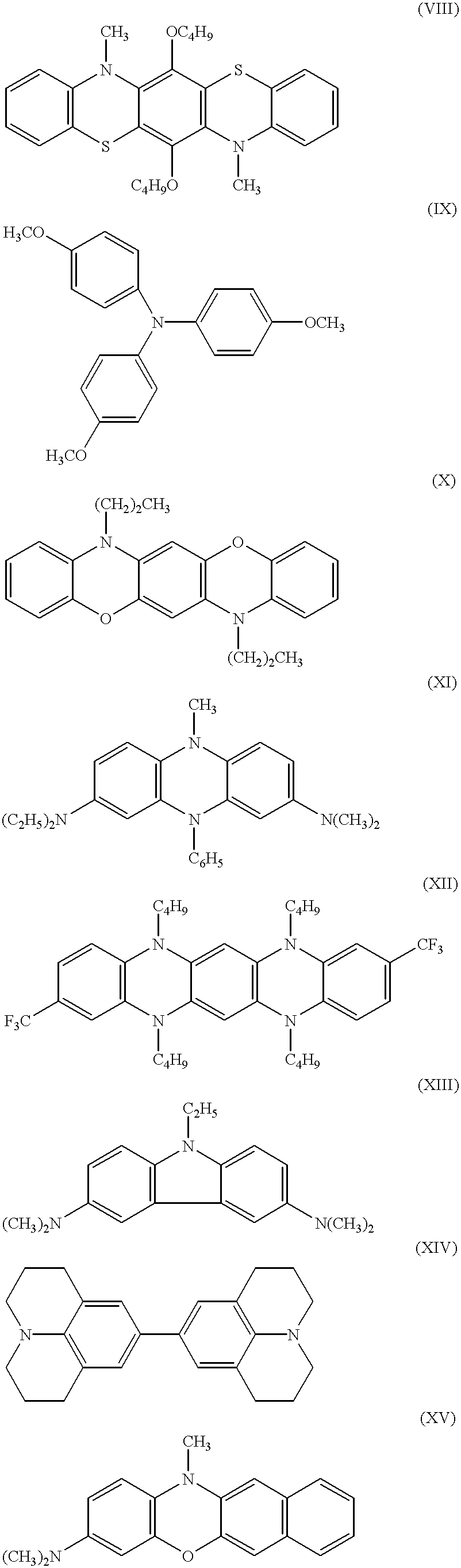


Table 1 contains the associated SOMO energy (ESOMO) and HDOMO energy (EHDOMO) levels (determined using AMPAC calculations), and the λmax and associated extinction coefficient (ε) values for the lowest energy absorption band of the corresponding cation radical for the above-referenced anodic electrochromic compounds. All spectroscopic data reported here are from the one electron oxidized form of the compounds. The spectra was collected using a window having two fluorine-doped tin oxide electrodes spaced apart approximately 137 microns by a perimeter seal and spacer. The volume inside was then filled with a solution of the anodic material with an equal or excess concentration of a viologen (1,1′-bis(3-phenyl(n-propyl))-4,4′-dipyridinium bis(tetrafluoroborate)) in propylene carbonate. The window was then attached to a DC power supply and a suitable voltage was applied to generate the cation radical (oxidized form) of the anodic material and the cation radical (reduced form) of the viologen which has a known spectrum. The viologen component was then subtracted out of the difference of the inactivated and activated spectra of the device, giving an accurate measure of the wavelength and extinction coefficients for the oxidized, cation radical form of the anodic material.
It is surprising that in this wide variety of compounds, the simple energy difference ESOMO−EHDOMO is a strong predictor of the lowest energy absorption band and that if AE is less than about 3.6 eV the compounds will have NIR activity. All the compounds in Table 1 are anodic, that is, in their fully reduced form they are colorless or nearly colorless, and when an electron is removed, they become colored. The compounds of the present invention, as illustrated by those listed in Table 1, are monomeric structures so there are no repeating units.
Table 1 also includes the redox potentials for compounds I-XIV, XXII and XXIII (using E1/2(1) of 5,10-dimethyl-5,10-dihydrophenazine in propylene carbonate equal to 0.300V as an arbitrary reference). As a general rule, it is preferred that the first redox potential of the anodic compound be greater than about 90-100 mV, on the scale used in this disclosure, since more easily oxidized materials are easily oxidized by atmospheric oxygen making processing difficult. Furthermore, the equilibrium for the electron transfer process, between an anodic compound and cathodic compound in a solution, is governed by the Nernst equation and an oxidation of at least 90-100 mV, combined with a typical aralkyl, bipyridinium compound, which has a reduction potential of approximately 300 mV and will result in a minimal zero potential concentration of oxidized or reduced material.
| TABLE 1 | ||||||
| Cation Radial | ||||||
| Of Compound | ESOMO | EHDOMO | ESOMO-EHDOMO | λmax(nm) | ε | E{fraction (1.2)} 1/E½ 2(eV) |
| I | −8.11 | −11.16 | 3.05 | 968 | 46,000 | 188/500 |
| II | −8.87 | −13.42 | 4.55 | 615 | 11,000 | 256/796 |
| III | −8.18 | −11.17 | 2.99 | 950 | 28,500 | 272/576 |
| IV | −8.87 | −12.95 | 4.08 | 727 | 1,500 | 300/980 |
| V | −8.41 | −11.74 | 3.33 | 924 | 15,000 | 412/812 |
| VI | −8.80 | −11.97 | 3.17 | 912 | 19,000 | 412/856 |
| VII | −8.08 | −10.95 | 2.87 | 966 | 20,000 | 488/872 |
| VIII | −8.27 | −10.74 | 2.47 | 1,198 | 38,500 | 648/932 |
| IX | −8.85 | −12.10 | 3.25 | 722 | 21,000 at | 700/1044 |
| 750 nm | ||||||
| X | −8.64 | −11.61 | 2.97 | 954 | 47,000 | 308/812 |
| XI | −7.82 | −11.01 | 3.19 | 804 | 14,000 | −166/308 |
| XII | −8.23 | −11.21 | 2.98 | 884 | 12,000 | −92/356 |
| XIII | −8.42 | −10.96 | 2.54 | 1694 | 15,000 | 404/476 |
| XIV | −8.20 | −11.08 | 2.88 | 316/492 | ||
| XV | −8.66 | −11.60 | 2.94 | |||
| XVI | −8.57 | −11.57 | 3.00 | |||
| XVII | −8.74 | −12.20 | 2.56 | |||
| XVIII | −8.44 | −11.45 | 3.01 | |||
| XIX | −8.80 | −11.53 | 2.73 | |||
| XX | −8.99 | −11.97 | 2.98 | |||
| XXI | −9.03 | −12.32 | 3.29 | |||
| XXII | −8.13 | −12.06 | 3.93 | 737 | 10,000 | 652/1105 |
| XXIII | −8.02 | −11.56 | 3.54 | 845 | 16,000 | 524/1002 |
| XXIV | −9.16 | −11.91 | 2.74 | |||
| XXV | −9.04 | −11.72 | 2.68 | |||
| XXVI | −8.73 | −12.23 | 3.42 | |||
| XXVII | −8.75 | −11.85 | 3.09 | |||
| XXVIII | −8.41 | −11.80 | 3.39 | |||
Included in Table 1, along with the absorption wavelengths are the molar extinction coefficients (ε). Assuming scattering effects are minimal, for a material to be useful in attenuating the solar energy entering a building it is desirable that it have a reasonably strong absorbance in the NIR portion of the electromagnetic spectrum. In the present invention, the NIR portion of the electromagnetic spectrum should be understood to range from about 750 nm to about 2400 nm. The ε values reported in Table 1 should be viewed as approximations to the oscillator strength. As those skilled in the art will appreciate, oscillator strength is a more appropriate value in determining whether a material will be a good IR absorber. We have, however, used the more commonly measured and reported ε values here. Compounds having values for ε of over 10,000 (between 750 and 2400 nm) will be considered strong NIR absorbers, while those having an ε of less than 5,000 (between 750 and 2400 nm) will be considered weak NIR absorbers.
As can be seen from Table 1,3,7-bis(dimethylamino)-10-methylphenothiazine (Compound III) has a HDOMO energy of −11.17 eV, a SOMO energy of −8.18 and a ΔE of 2.99 eV. FIG. 2 is a graph of the absorption versus wavelength for the cation radical of Compound III and shows the λmax for this cation radical to be at 950 nm (in the NIR portion of the electromagnetic spectrum). In addition, at 950 nm this compound has an ε of 28,500 which makes this compound, which has only modest visible light absorbance (λmax=474, ε=4000) a good candidate for a NIR absorbing electrochromic compound.
FIG. 3 shows a graph of the absorbance versus wavelength for the cation radical of 3-dimethylamino-7-methoxy-10-methylphenothiazine (compound V) in propylene carbonate and shows the λmax for this cation radical to be at 924 nm (in the NIR portion of the electromagnetic spectrum). In addition, at 924 nm this compound has an ε of about 15,000 which makes this compound a good candidate for a NIR absorbing electrochromic compound.
FIG. 4 shows a graph of the absorbance versus wavelength for the cation radical of [a]benzo-7-dimethylaminophenoxazine (compound VI) in propylene carbonate and shows the λmax for this cation radical to be at 912 nm (in the NIR portion of the electromagnetic spectrum). In addition, at 912 nm this compound has an ε of approximately 19,000 which makes this compound a good candidate for a NIR absorbing electrochromic compound.
As stated above, in conjunction with the ESOMO−EHDOMO value, the predictor of NIR activity is whether the transition moment of the configuration made up of the HDOMO and SOMO is “long axis polarized.” The intensity of an absorption band can be calculated using the “transition density.” The transition density of a configuration is the outer product of the molecular orbitals involved in the configuration, i.e., the outer product of the SOMO and HDOMO wavefunctions. Thus the outer product or matrix product of two vectors 
would be the matrix 
From the transition density, transition dipole moments can be determined. It is also possible to calculate the transition probabilities from state to state, i.e., the probability of the molecule going from the ground state to an excited state can be calculated. The transition dipole moment is calculated in a way that is similar to calculating the ground state dipole moment, by multiplying the transition density at an atomic center by the coordinate of the center. The intensity of an absorption band is related to the square of the transition dipole moment.
As stated above, we have found that the transition dipole moment that has a “long axis” primary component are compounds with strong absorbances. The compounds of the present invention fall into 2 broad categories. The first is the “5,10-dihydroanthracene type” which includes phenazine, phenoxazine, and phenothiazine as well as triphenodioxazine and triphenodithiazine compounds. These compounds have a short axis that runs from heteroatom to heteroatom in the ring system. For example, the nitrogen and oxygen would be heteroatoms in the substituted phenoxazine compound. The carbazole can be thought of in a similar way to the phenazine and phenoxazines. Also, the azines have their long axis perpendicular to the Y-axis. The second type is 1,4 disubstituted benzenes, which have their long axis running through the 1 and 4 positions of the benzene ring and the short axis from the midpoint of the 2-3 and to the midpoint of the 5-6 bond.
The structures of the compounds shown above are oriented so that their long axis is horizontal, i.e., parallel with the X-axis of the illustrated coordinate system. Table 2 lists the transition dipoles for the compounds and repeats the extinction coefficients from Table 1. It is seen that strong absorption bands are associated with larger x-components of the transition dipole. These long axis polarized transition dipoles are indicators of compounds that can be used as effective electrochromic materials. As can be seen from Table 2, compounds I, III, V-XXI and XXIII all have large x-components of their transition dipole, and they all have strong NIR absorbance. Compound IV, on the other hand, has a larger y-component of its transition dipole and does not have NIR activity. Compounds II and XXII, with their larger energy gap (greater than 3.6 eV) do not have NIR activity.
The use of orbital energy differences and transition density orientations to predict NIR active compounds is somewhat surprising since the possibility of repulsion due to largely localized orbitals is not taken into account. However, in view of the inventors discoveries, and armed with the knowledge of molecular orbital energies and transition dipole vectors, one can identify new materials with NIR activity, as well as revisit materials that may not have strong visible light (400-750 nm) absorption but could have NIR activity. The materials outlined in Tables 1 and 2 that exhibit NIR activity are not exhaustive and all compounds that meet the criteria outlined above should be understood to be a part of the present invention.
| TABLE 2 | ||
| Cation Radical | Transition Dipole (Absolute Value) | |
| of Compound | X | Y | Z | ε (from Table 1) |
| I | 3.87 | 0.49 | 0.27 | 46,000 |
| II | 3.17 | 0.006 | 0.0078 | 11,000 |
| III | 3.89 | 0.11 | 0.19 | 28,500 |
| IV | 0.0097 | 1.34 | 0.032 | 1,500 |
| V | 2.88 | 0.29 | 0.05 | 15,000 |
| VI | 3.77 | 0.56 | 0.27 | 19,000 |
| VII | 3.51 | 0.15 | 0.32 | 20,000 |
| VIII | 4.63 | 0.47 | 0.27 | 38,500 |
| IX | 3.11 | 0.67 | 0.44 | 21,000 at |
| 750 nm | ||||
| X | 3.72 | 0.53 | 0.55 | 47,000 |
| XI | 3.80 | 0.06 | 0.22 | 14,000 |
| XII | 4.34 | 0.13 | 0.19 | 12,000 |
| XIII | 3.76 | 0.15 | 0.007 | 15,000 |
| XIV | 5.05 | 0.14 | 0.04 | |
| XV | 0.96 | 0.41 | 0.076 | |
| XVI | 3.34 | 0.47 | 0.16 | |
| XVII | 3.28 | 0.40 | 0.066 | |
| XVIII | 2.89 | 0.027 | 0.20 | |
| XIX | 3.55 | 0.38 | 0.22 | |
| XX | 3.09 | 0.049 | 0.010 | |
| XXI | 3.41 | 0.29 | 0.39 | |
| XXII | 3.15 | 1.49 | 3.93 | 10,000 |
| XXIII | 3.59 | 0.25 | 0.016 | 16,000 |
| XXIV | 1.76 | 0.006 | 0.0004 | |
| XXV | 1.26 | 0.07 | 0.0002 | |
| XXVI | 2.41 | 0.004 | 0.035 | |
| XXVII | 0.39 | 0.007 | 0.0007 | |
| XXVIII | 1.14 | 0.0067 | 0.0016 | |
In accordance with another aspect of the present invention, the above-described NIR active electrochromic compounds can be included as part of the electrochromic medium 124 into the electrochromic device 110 (see FIG. 1). FIG. 5 shows a graph of the mW per square meter per nanometer versus wavelength for the electrochromic device of Example 1 containing an electrochromic medium comprising tris(dimethylaminophenyl)-amine (compound I) combined with 1,1′-bis(3-phenyl(n-propyl))-4,4′-dipyridinium bis(tetrafluoroborate) and propylene carbonate. The tris(dimethylaminophenyl)-amine has a ESOMO−EHDOMO of 3.05, an ε of 46,000 and the transition moment of the configuration made up of the HDOMO and SOMO is “long axis polarized.” In FIG. 5, Curve A represents the absolute solar intensity (in mW per square meter per nanometer) at each wavelength, Curve B represents the amount of solar radiation that is transmitted through the electrochromic device in its clear (or zero applied potential) state. Curve C represents the amount of solar radiation that is transmitted through an electrochromic device in its activated colored or darkened state. Table 3 shows the percent transmission for the total solar region, the UV spectral region, the visible region and the NIR region for the same electrochromic device in its clear and darkened state. As can be seen from Table 3, this electrochromic device transmitted 55.6 percent of the total solar radiation, 5.8 percent of the UV radiation, 73.8 percent of the visible radiation and 46.2 percent of the NIR region in its clear state. In its darkened state the device transmitted 10.2 percent of the total solar radiation, 0.0 percent of the UV radiation, 8.4 percent of the visible radiation and 13.6 percent of the NIR radiation. Thus, this device attenuated the NIR portion of the electromagnetic spectrum by 70.6 percent and the total solar radiation by 81.7 percent.
| TABLE 3 | |||
| Wavelength | % Transmission | % Transmission | |
| Range | Spectral Region | In Clear State | In Dark State |
| 300 to 400 | UV | 5.8 | 0.0 |
| 400 to 750 | Visible | 73.8 | 8.4 |
| 750 to 2400 | NIR | 46.2 | 13.6 |
| 300 to 2400 | Total Solar | 55.6 | 10.2 |
As a comparison, FIG. 6 shows a graph of the mW per square meter per nanometer versus wavelength for the electrochromic device of Example 2 containing compound IV (5,10-dimethyl-5,10-dihydrophenazine) combined with 1,1′-bis(3-phenyl(n-propyl))-4,4′-dipyridinium bis(tetrafluoroborate) and propylene carbonate. Compound IV has a ESOMO−EHDOMO of 4.08, and an ε of 1,500 for the lowest energy absorption band, and the transition moment of the configuration made up of the HDOMO and SOMO is “short axis polarized.” In FIG. 6, Curve A represents the absolute solar intensity (in mW per square meter per nanometer) at each wavelength, Curve B represents the amount of solar radiation that is transmitted through an electrochromic device in its clear (or zero applied potential) state. Curve C represents the amount of solar radiation that is transmitted through an electrochromic device in its dark state. Table 4 shows the percent transmission for the total solar region, the UV spectral region, the visible region and the NIR region for the same electrochromic device in its clear and darkened state. As can be seen from Table 4, this electrochromic device, in its clear state, transmitted 60.3 percent of the total solar radiation, 7.6 percent of the UV radiation, 74.5 percent of the visible radiation and 55.4 percent of the NIR region. In its darkened state the device transmitted 27.4 percent of the total solar radiation, 0.0 percent of the UV radiation, 8.9 percent of the visible radiation and 50.0 percent of the NIR radiation. Thus, this device attenuated the NIR portion of the electromagnetic spectrum by only 10 percent and the total solar radiation by 54.6 percent.
| TABLE 4 | |||
| Wavelength | % Transmission | % Transmission | |
| Range | Spectral Region | In Clear State | In Dark State |
| 300 to 400 | UV | 7.6 | 0.0 |
| 400 to 750 | Visible | 74.5 | 8.9 |
| 750 to 2400 | NIR | 55.4 | 50.0 |
| 300 to 2400 | Total Solar | 60.3 | 27.4 |
Clearly, as the above comparison illustrates, a compound with a ESOMO−EHDOMO of less than 3.6 and where the transition moment of the configuration made up of the HDOMO and SOMO is “long axis polarized” has significantly more NIR activity than a compound that does not have these characteristics. In addition, a compound that has a larger ε is also advantageous.
Table 5 shows the absorption data for the electrochromic device of Example 2 containing compound I (tris(dimethylaminophenyl) amine combined with 1,1′-bis(3-phenyl(n-propyl))-4,4′-dipyridinium bis(tetrafluoroborate) and propylene carbonate. In addition, the electrochromic medium contained about 8.5% of a crosslinked polymer matrix containing 1:10 isocyanatoethylmethacrylate to methylmethacrylate crosslinked with Bisphenol A. Compound I has an ESOMO−EHDOMO of 3.05, and an E of 46,000 for the lowest energy absorption band, and the transition moment of the configuration made up of the HDOMO and SOMO is “long axis polarized”.
| TABLE 5 | |||
| Wavelength | % Transmission | % Transmission | |
| Range | Spectral Region | In Clear State | In Dark State |
| 300 to 400 | UV | 11.4 | 0.1 |
| 400 to 750 | Visible | 76.0 | 17.1 |
| 750 to 2400 | NIR | 46.3 | 15.2 |
| 300 to 2400 | Total Solar | 57.0 | 14.9 |
As can be seen from Table 5, this electrochromic device, in its clear state, transmitted 57 percent of the total solar radiation, 11.4 percent of the UV radiation, 76 percent of the visible radiation and 46.3 percent of the NIR region. In its darkened state, the device transmitted 14.9 of the total solar radiation, 0.1 percent of the UV radiation, 17.1 percent of the visible radiation and 15.2 percent of the NIR radiation.
In another of its embodiments, the present invention entails compounds of the general formula: 
where
R1-R2, R2-R3 or R3-R4 is benzo,
X1 is NR6, O, S or Se,
Y1 is H, NR7R8, or OR9
Y2 is H, NR7R8 or OR9,
where at least one of Y, or Y2 is NR7R8, and where R5-9 may be independently chosen from the group consisting of alkyl, aryl or aralkyl having from 1 to 20 carbon atoms.
Compounds fitting the above general structure XXIX include compounds VI, XV, XVI, XVIII, XIX and XXI, although those skilled in the art will appreciate that using the teachings of the present invention, many more compounds having NIR activity may be prepared. All such compounds are intended to be a part of the present invention.
In yet another of its embodiments, the present invention entails compounds of the general formula: 
where
X1 is NR2, O, S or Se;
Y1 is NR7R8 or OR9;
Y3 is NR7R8
and where R2, and R7-R10 may be independently chosen from the group consisting of alkyl, aryl or aralkyl having from 1 to 20 carbons.
Compounds fitting the above general structure XXX include compounds III, V, and XI, although those skilled in the art will appreciate that using the teachings of the present invention, many more compounds having NIR activity may be prepared. All such compounds are intended to be a part of the present invention.
In yet another of its embodiments, the present invention entails compounds of the general formula: 
where
X2 and X3 are independently selected from the group consisting of O, S and NR19
R11-R14 are independently selected from the group consisting of CF3,
H, or alkyl having from 1 to 10 carbon atoms;
R15 and R16 are independently selected from the group consisting of H or OR17; and
R17-R19 are alkyl having from 1 to 10 carbon atoms.
Compounds fitting the above general structure include compounds VIII, X and XII, although those skilled in the art will appreciate that using the teachings of the present invention, many more compounds having NIR activity may be prepared. All such compounds are intended to be a part of the present invention.
In still another of its embodiments, the present invention entails compounds of the general formula: 
where
X4 is O, S, NR22, or a single bond,
X5 is O, S, or a single bond,
where at least one of X4 or X5 is a single bond, and
R20-R22 may be independently chosen from the group consisting of alkyl, aryl or aralkyl having from 1 to 20 carbons.
Compounds fitting the above general structure include compounds XXIV through XXVIII, although those skilled in the art will appreciate that using the teachings of the present invention, other compounds having NIR activity may be prepared, and that all such compounds are intended to be a part of the present invention.
Compositions of the invention, which are media of reversibly variable transmittance in electrochromic devices, may also comprise an inert, current carrying electrolyte, particularly if there is no electrochromic compound which is ionic in its equilibrium state in an electrochromic device with no potential difference between the cathode and anode. Such inert, current-carrying electrolytes are well known in the art. Examples are provided in U.S. Pat. No. 4,902,108.
Compositions of the invention, which are media of reversibly variable transmittance in electrochromic devices, may also include a polymeric thickener. In this regard, reference is also made to U.S. Pat. No. 4,902,108, and U.S. patent application Ser. No. 08/834,783 now U.S. Pat. No. 5,940,201, entitled “An Electrochromic Mirror with Two Thin Glass Elements and a Gelled Electrochromic Medium.” While many such thickeners are known, polyethylene oxide and “PMMA” (polymethylmethacrylate), and certain PMMA copolymers disclosed in U.S. patent application Ser. No. 08/834,783 now U.S. Pat. No. 5,940,201 are preferred.
Electrochromic devices, which comprise as the medium of reversibly variable transmittance a composition according to the invention, are also encompassed by the present invention. Preferred among these are solution-phase, single-compartment, self-erasing devices, although those skilled in the art will appreciate that hybrid electrochromic devices may be used. These hybrid electrochromic devices comprise a solution-phase electrochromic compound in combination with either a surface confined electrochromic layer or an electrodeposition-type electrochromic material.
Thus, in another of its embodiments, the invention entails, in a single-compartment, self-erasing, solution-phase electrochromic device which comprises, as the medium of reversibly variable transmittance to light, an aprotic polar solvent, and at least one electrochromic compound of the present invention that absorbs in the NIR portion of the electromagnetic spectrum. Preferably, the electrochromic device comprises, as the medium of reversibly variable transmittance to light at least one anodic electrochromic compound and at least one cathodic electrochromic compound, where at least one of the electrochromic materials absorbs in the NIR portion of the electromagnetic spectrum. The devices of the invention can be employed as the variable transmittance components of variable transmission light filters, such as windows, or variable reflectance mirrors, including anti-glare, outside and inside, rearview mirrors for motor vehicles. Construction of single-compartment, self-erasing, solution-phase electrochromic devices according to the invention are described in U.S. Pat. No. 4,902,108.
The electrochromic medium optionally comprises the electrochromic materials, and other materials like solvents, light absorbers, light stabilizers, UV stabilizers, thermal stabilizers, antioxidants, tint-providing compounds, and a freestanding gel.
The NIR absorbing compounds of the present invention will be advantageously used in windows (typically large area windows) where heat transfer from the outside of the building to the inside of the building is important. Large area devices that have a solution as some part of the electrochromic medium suffer from hydrostatic pressure. To help alleviate this problem a freestanding gel (which includes a polymer matrix) may be incorporated as part of the electrochromic medium.
The polymer matrix that may optionally be used is disclosed in either U.S. Pat. No. 5,679,283 or in commonly assigned co-pending U.S. patent application Ser. No. 08/616,967 now U.S. Pat. No. 5,928572, entitled “IMPROVED ELECTROCHROMIC LAYER AND DEVICES COMPRISING SAME” to W. L. Tonar et al. For electrochromic windows (especially larger windows), the polymer matrix cooperatively interacts with glass elements 112 and 114 such that the hydrostatic pressure that typically occurs from gravity acting on the electrochromic medium (when the electrochromic medium includes a solution) is reduced or eliminated.
The polymer matrix may comprise at least one polymer based on the vinyl polymerization of a molecule having the general formula: 
where R1 is optional and may be selected from the group consisting of: alkyl, cycloalkyl, poly-cycloalkyl, heterocycloalkyl, carboxyl and alkyl and alkenyl derivatives thereof; alkenyl, cycloalkenyl, cycloalkadienyl, poly-cycloalkadienyl, aryl and alkyl and alkenyl derivatives thereof, hydroxyalkyl; hydroxyalkenyl; alkoxyalkyl; and alkoxyalkenyl where each of the compounds has from 1 to 20 carbon atoms. R2 is optional and may be selected from the group consisting of alkyl, cycloalkyl, alkoxyalkyl, carboxyl, phenyl and keto where each of the compounds has from 1-8 carbon atoms, and oxygen. R3, R4, and R5 may be the same or different and may be selected from the group consisting of: hydrogen, alkyl, cycloalkyl, poly-cycloalkyl, heterocycloalkyl, and alkyl and alkenyl derivatives thereof; alkenyl, cycloalkenyl, cycloalkadienyl, poly-cycloalkadienyl, aryl and alkyl and alkenyl derivatives thereof; hydroxyalkyl; hydroxyalkenyl; alkoxyalkyl; alkoxyalkenyl; keto; acetoacetyl; vinyl ether and combinations thereof, where each of the compounds has from 1 to 8 carbon atoms. Finally, B may be selected from the group consisting of hydroxyl; cyanato; isocyanato; isothiocyanato; epoxide; silanes; ketenes; acetoacetyl, keto, carboxylate, imino, amine, aldehyde and vinyl ether. However, as will be understood by those skilled in the art, if B is an cyanato, isocyanato, isothiocyanato, or aldehyde it is generally preferred that R1, R2, R3, R4, and R5 not have a hydroxyl functionality.
Preferred among the monomers is methyl methacrylate; methyl acrylate; isocyanatoethyl methacrylate; 2-isocyanatoethyl acrylate; 2-hydroxyethyl methacrylate; 2-hydroxyethyl acrylate; 3-hydroxypropyl methacrylate; glycidyl methacrylate; 4-vinylphenol; acetoacetoxy methacrylate and acetoacetoxy acrylate.
The monomers should also preferably be capable of pre-polymerization. By pre-polymerization we mean that the monomers and/or precursors react with one another to produce relatively long and relatively linear polymers. This pre-polymerization is substantially free of any crosslinking reactions, and is generally accomplished as follows. A certain amount of the monomer(s) is dissolved in a suitable solvent; the solution may be optionally purged with an inert gas such as nitrogen, argon or helium, and at least one electrochromic species may optionally be added. The polymerization reaction is initiated by known techniques, e.g., heat, photo and/or chemical initiator such as azo or peroxide initiators, and long and primarily linear chains of the polymer are built through a simple addition reaction.
It should be understood that more than one monomer might be pre-polymerized together. Equation [1] shows the general formula for the monomers, and any of the combinations of the monomers shown may be combined into one or more polymers (i.e., a polymer, a copolymer, terpolymer, etc.) in the pre-polymerization process. For example, one monomer may be polymerized to give a homogeneous polymer material such as poly(2-hydroxyethyl methacrylate), poly(2-isocyanatoethyl methacrylate), and the like. However, it is generally preferred that a species with a crosslinking reactive component (e.g., hydroxyl, acetoacetyl, isocyanate, thiol etc.) be combined with another species either having the same crosslinking reactive component or no crosslinking reactive component (e.g., methyl methacrylate, methyl acrylate, etc.). If a copolymer is produced, the ratio of the monomers without and with the crosslinking components may range from about 200:1 to about 1:200. Although the following description relates to copolymers, it will be understood by those skilled in the art that more complex structures (terpolymers, etc.) may be made using the same teachings.
For example, 2-isocyanatoethyl methacrylate (IEMA) may be combined with MMA in the ratio of about 1:3 to about 1:50 with the preferred ratio of about 1:20. Crosslinking of a group containing an isocyanate can occur with any compound containing a reactive hydrogen, such as hydroxyl, thiol, acetoacetyl, urea, melamine, urethanes, with hydroxyl being presently preferred. These should have a functionality greater than one and may be the same as those described hereinabove, aliphatic or aromatic compounds or, preferably, may be 1,3-hydroxy benzene.
Further, two copolymers may be combined such that they crosslink with one another. For example 2-hydroxyethyl methacrylate (HEMA)/MMA may be combined with IEMA/MMA and the hydroxyl groups of HEMA will self-react with the isocyanate groups of IEMA to form an open polymeric structure. It should be understood that the rates of crosslinking for any of the polymers described herein could be controlled by proper selection of the reactive crosslinking species employed. For example, using an aromatic isocyanate or an aromatic alcohol or both can increase reaction rates. Reaction rates can be decreased, for example, by using sterically hindered isocyanates or sterically hindered alcohols or both.
An improved UV stabilizer is described and claimed in co-pending U.S. patent application Ser. No. 08/906,750 now U.S. Pat. No. 5,770,114, entitled “UV-STABILIZED COMPOSITIONS WITH IMPROVED SOLUBILITY”, filed on or about Aug. 6, 1997. The compounds described in this Application have increased solubility in aprotic polar solvents used in electrochromic devices and are much more effective in stabilizing compositions, which comprise at least one electrochromic compound and are useful as media of variable transmittance in electrochromic devices, against degradation due to exposure to UV-radiation than prior UV stabilizers.
Components of the solutions of electrochromic compounds described herein, absorb UV photons and, as a consequence, may undergo degradative reactions upon exposure to UV light. Thus, windows and rearview mirrors, wherein such solutions are employed to provide variable transmittance or reflectance, have useful lifetimes significantly limited in environments, such as on the exterior and certain places on the interior of buildings, or on the exterior and certain places on the interior of automobiles, where they are exposed for extended periods of time to ultraviolet light, as from the sun.
There has existed a need, then, to stabilize materials, which comprise UV-radiation-absorbing compounds, against degradation caused by exposure to UV-light. Many ultraviolet absorbers or stabilizer agents, that are compounds that provide such stabilization, when combined with materials susceptible to UV-degradation, are known in the art. Ultraviolet absorbers or stabilizer agents absorb ultraviolet radiation competitively with other compounds in a stabilized composition or are capable, without decomposition of the stabilizer itself, of dissipating the energy acquired upon absorption of a UV-photon by the materials being stabilized. Such agents must also satisfy a number of other requirements, depending on properties of the compositions to be stabilized. For example, the agents must be sufficiently soluble in such a composition and must not interact with other components in the composition in a way that interferes with using the composition for its intended purpose. Thus, an ultraviolet stabilizer agent for use in a solution employed as a medium of variable transmittance to visible light in an electrochromic device must not interact with the electrochromic compounds or other components of the medium in a way such that they cease to function effectively in the medium and it must not compete with the electrochromic compounds for oxidation or reduction at the electrodes of an electrochromic device.
Among ultraviolet stabilizer agents, known to stabilize plastics, are the compound ethyl-2-cyano-3,3-diphenyl acrylate, sold by BASF (Parsippany, NJ) under the trademark Uvinul N-35 and by Aceto Corporation (Flushing, N.Y., USA) under the trademark Viosorb 910; the compound (2-ethylhexyl)-2-cyano-3,3-diphenyl acrylate, sold by BASF under the trademark Uvinul N-539; the compound 2-(2′-hydroxy-4′-methylphenyl)benzotriazole, sold by Ciba-Geigy Corp. under the trademark Tinuvin P; the compound 2-hydroxy-4-methoxybenzophenone, sold by American Cyanamid under the trademark Cyasorb UV 9; and the compound 2-ethyl-2′-ethoxyoxalanilide, sold by Sandoz Color & Chemicals under the trademark Sanduvor VSU.
Referring again to FIG. 1, during operation of an electrochromic window or device in the clear state, light rays enter through the front glass 112 and pass through the transparent conductive layer 116 the electrochromic medium in chamber 122, and finally the back glass 114 of the window 110. When a sufficiently high voltage is applied to an electrochromic device, electrochemical reduction takes place by electron transfer to the electrochromic medium from one of the electrodes (designated as the cathode) and electrochemical oxidation takes place by electron transfer from the electrochromic medium to the other electrode (designated as the anode). The electrochemical reduction and/or the electrochemical oxidation give rise to a change in the light absorption properties of the material or materials reduced and/or oxidized. This change in light absorption can be a combination of both the anodic and cathodic electrochromic compounds and changes the absorption characteristics of the UV, visible and NIR portions of the electromagnetic spectrum attenuated in proportion to the degree to which the electrochromic medium 124 is light absorbing. Thus, operation, or activation, of the device generally results in an increase in light absorption at the wavelengths of interest (e.g., visible and NIR) although it is possible for operation of an already colored device to result in a decrease in light absorption at the wavelengths of interest.
Another embodiment of the present invention is shown in FIG. 7. This embodiment takes advantage of the fact that a substantial amount of the solar energy is absorbed by devices of the invention and that, by combining these devices with one or more coatings that have high infrared reflection and low infrared emission, a device is provided having exceptional solar energy barrier properties when activated. The advantages of the combination of the one or more coatings, which each have high infrared reflection and low infrared emission and are normally referred to as Low-E coatings, with the strong solar absorption of the electrochromic media of the present invention, are preferably achieved as shown in FIG. 7. An insulated glass unit 701 may be combined with an electrochromic device 110. Coatings 702 and 703 are Low-E coatings, such as fluorine-doped tin oxide, indium-doped tin oxide, a multi-layer coating of zinc oxide, silver and zinc oxide or the like.
Depending on the desired result, either coating 702 or coating 703 or both may be included. When the electrochromic device 110 is activated and thus absorbing solar energy, a layer of a Low-E coating 702 by itself can serve to minimize energy transfer across the gap 704, (where 704 is a space filled with dry air or an inert gas with a spacing set to minimize energy transfer by convection), to element 706 and thus to the interior 710 of the building or other structure. Alternatively coating 703 by itself will reflect radiation from the electrochromic device 110 back to device 110 so the energy can be radiated to the surroundings on the outdoor side 708 of device 110. If both 702 and 703 are included, radiant energy from 110 is blocked from entering the indoors by both the low infrared emission from 702 and the high infrared reflection of 703 thus inhibiting the black body radiation of electrochromic device 110, (warmed by solar energy absorption), from being absorbed by 706 and then being re-radiated to the interior 710 of the building or other structure.
The Low-E coating(s) used should be good at reflecting and poor at radiating the longer wavelength infrared radiation radiated from a warm electrochromic device and should still pass the shorter wavelength radiation contained in sunlight. This allows the window or device structure in FIG. 7 to pass visible and NIR solar energy on cold days or in the winter when the device is not activated and be a high efficiency energy barrier when the device is activated.
The following illustrative examples are not intended to limit the scope of this invention but to illustrate its application and use:
Two stock solutions, one containing 28 mM tris(4-dimethylaminophenylamine) in propylene carbonate and the other containing 34 mM bis(3-phenylpropyl)-4,4′-dipyridinium) bis(tetrafluoroborate) in propylene carbonate were prepared in separate small vials. Both stock solutions were deoxygenated with dry nitrogen. Equal volumes of each stock solution were introduced into a clean vial. This mixture was then used to fill electrochromic devices.
Electrochromic window devices were fabricated as is known in the art with TEC-15 glass from Libbey-Owens-Ford with a 137-micrometer cell spacing. The devices were about 1′×2″ in area and were filled by introducing the solution described above into the device through one of two holes drilled in the top plate. Both holes were then plugged using a hot melt adhesive.
The transmission spectrum was measured in the range of 300-2400 nm and the % T at 0.0 V and 1.2 V were multiplied by the solar contribution at each wavelength resulting in the % total solar transmission of 56.0% at 0.0 V and 16.2% at 1.2 V.
A window similar to Example 1, except the solution contained 28 mM 5,10-dihydro-5,10-dimethylphenazine and 34 mM bis(3-phenyl(n-propyl))-4,4′-dipyridinium) bis(tetrafluoroborate) in propylene carbonate. The total solar transmission for this window was 59.7% at 0.0 V and 26-28% at 1.2 V.
Window similar to Example 1, except the solution contained 10 mM bis(3-phenyl(n-propyl))-4,4′-dipyridinium) bis(tetrafluoroborate) saturated with N,N,N′,N′-tetraanisyl-1,4-phenylenediamine in propylene carbonate. This spectrum was then normalized to 30 mM in both the anodic and cathodic material in a device, giving a total solar % transmission of about 52% at 0.0 V and about 4% at 1.2 V.
Window similar to Example 1, except the solution contained 10 mM bis(3-phenyl(n-propyl))-4,4′-dipyridinium) bis(tetrafluoroborate) saturated at room temperature with 3-dimethylamino-7-methoxy-10-methylphenathiazine. This spectrum was then normalized to 30 mM in both the anodic and cathodic material in a device, giving a total solar % transmission of about 56% at 0.0 V and about 12% at 1.2 V.
Window similar to Example 1, except the solution contained 10 mM bis(3-phenyl(n-propyl))-4,4′-dipyridinium) bis(tetrafluoroborate) and 10 mM [a]-benzo-7-dimethylaminophenoxazine in propylene carbonate. This spectrum was then normalized to 30 mM in both the anodic and cathodic material in a device, giving a total solar % transmission of about 56% at 0.0 V and about 17% at 1.2 V.
Window similar to Example 1, except the solution contained 10 mM bis(3-phenyl(n-propyl))-4,4′-dipyridinium) bis(tetrafluoroborate) saturated with N, N-dipropyltriphenodioxazine. This spectrum was then normalized to 30 mM in both the anodic and cathodic material in a device, giving a total solar % transmission of about 52% at 0.0 V and about 14% at 1.2 V.
[a]benzo-7,N,N-dimethylamino-10-methylphenoxazine (compound VI) was formed in a 2-step process.
In the first step, 6.2 g of Meldola's Blue dye was reduced to its “leuco” form by dissolving it in 50 ml of water and adding to it an aqueous solution containing 17.4 g of sodium dithionite (Na2S2O4). From the blue solution precipitated a tan-colored solid, which is the leuco form of the dye. This solid was filtered off and dried under vacuum.
In the second step, the reduced dye was dissolved in 100 ml of dry tetrahydrofuran and to it was added 3 equivalents of phenyl lithium. The lithio derivative that formed precipitated out of the tetrahydrofuran solution. After ½ hour, 2 equivalents of iodomethane were added and the reaction allowed to stir at room temperature for four hours. The THF reaction solution was passed over a silica gel column to isolate the methylated product. It was recrystallized from ethanol to yield 0.4 grams of a light yellow granular solid. The compound was characterized by mass spectral analysis.
3-methoxy-7-N,N-dimethylamino-10-methylphenothiazine (Compound V) was produced from a 2-step process.
In the first step, methylene violet was reduced to its leuco form by dissolving it in methanol then adding 10% Pd/C as catalyst and finally hydrazine as a reducing agent. After one hour of stirring at room temperature, the “leuco” or reduced form of methylene violet precipitated out of solution and was filtered off. This intermediate product was then dried under vacuum.
In the second step, this dried leuco intermediate was added to a deoxygenated solution of DMSO containing an excess of dissolved potassium hydroxide. This mixture was stirred for ½ hour to allow for formation of the potassium salt, after which was added two equivalents of iodomethane. The reaction mixture was stirred for 6 hours at room temperature, after which water and ethyl acetate were added to it. The resulting mixture was stirred and after settling the lower layer was discarded. The water wash was repeated two more times, then the ethyl acetate layer was concentrated and re-dissolved in toluene. Product was isolated from this solution using silica gel column chromatography to purify. Fractions containing product were concentrated during which the white crystalline product precipitated. The compound was characterized by mass spectral analysis.
Bis-3,7-N,N-dimethylamino-10-methylphenothiazine (Compound III) was prepared in a 2-step synthesis.
In the first step, the starting material, methylene blue, was reduced to its “leuco” form by dissolving in water and adding to it 2 equivalents of sodium dithionite (Na2S2O4) in an aqueous solution. The leuco form of methylene blue precipitated out of the aqueous solution as a tan solid and was isolated with vacuum filtration.
In the next step, 1 equivalent of potassium hydroxide was added to deoxygenated dimethylsulfoxide and was stirred for 15 minutes. The filter cake, from above, was added to the DMSO reaction slurry and was stirred for ½ hour to allow for the potassium salt formation of the phenothiazine. To this solution was added 1.5 equivalents of iodomethane and the reaction mixture was stirred for four hours at room temperature. Water and ethyl acetate were added to the DMSO reaction solution and the mixture was stirred to extract product into the ethyl acetate layer. The water layer was discarded. The ethyl acetate layer, containing methylated product, was concentrated then dissolved in acetone. The acetone solution was loaded to a silica gel column, from which the white crystalline product was isolated. The compound was characterized by mass spectral analysis.
7,14-dipropyltriphenodioxazine (Compound X) was prepared as follows:
Triphenodioxazine (24.4 mM) was added to a stirred suspension of potassium (100 mg) in dry 1,2-dimethoxyethane (150 ml) under an argon atmosphere at room temperature. The resulting red/brown-colored mixture was warmed to approximately 60 degrees Celsius and was kept stirred at this temperature for 41 hours. After this period, the mixture was cooled to room temperature and the triphenodioxazine dianion was quenched with 1-iodopropane (0.08 mol). After brief stirring, the unreacted metal was destroyed with a few milliliters of absolute ethanol and the reaction mixture was evaporated to dryness to leave behind a dark colored crude material. Silica gel chromatography of the crude material with a hexane, ethyl acetate, and methanol mixture as the eluting solvent yielded the desired product in low yield. Recrystallization of the product from absolute methanol yielded a straw-yellow solid (m.p. 159-160 degrees Celsius). The compound was characterized by mass spectral analysis.
While the invention has been described in detail herein in accordance with certain preferred embodiments thereof, many modifications and changes therein may be effected by those skilled in the art without departing from the spirit of the invention. Accordingly, it is our intent to be limited only by the scope of the appending claims and not by way of the details and instrumentalities describing the embodiments shown herein.
Claims (39)
1. An electrochromic medium comprising at least one solution-phase anodic compound, where an oxidized form of said anodic compound has a ESOMO−EHDOMO of less than 3.6 eV, a redox potential greater than about 90 mV, and an absorption band having a λmax greater than approximately 750 nm, excluding therefrom the compounds of the formula: 
wherein R51 and R54 are the same or different and are each selected from hydrogen and dialkylamino, wherein the alkyl groups are the same or different and are each of 1 to 6 carbon atoms, R52 is oxygen, sulfur or NR55, wherein R55 is the same as or different from R53 and both R55 and R53 are selected from hydrogen, alkyl of 1 to 10 carbon atoms, phenyl optionally substituted at any one position with chloride, bromide, iodide, cyano, or alkyl of 1 to 4 carbon atoms, or benzyl, optionally substituted at any one position of the phenyl group with chloride, bromide, iodide, cyano, or alkyl of 1 to 4 carbon atoms.
2. The medium of claim 1, wherein said oxidized form of said anodic compound is capable of absorbing in the NIR portion of the electromagnetic spectrum.
3. The medium of claim 1, wherein said medium is self-erasing.
4. The medium of claim 1, wherein said medium is solution-phase.
5. The medium of claim 1, wherein the outer product of the SOMO and HDOMO of said anodic compound results in a long axis transition dipole moment.
6. The medium of claim 5, wherein said oxidized form of said anodic compound is capable of absorbing in the NIR portion of the electromagnetic spectrum and where said electrochromic medium further comprises a solvent and a cathodic electrochromic material.
7. The medium of claim 6, wherein said medium is self-erasing.
8. The medium of claim 6, wherein said medium is solution-phase.
9. The medium of claim 6, wherein said anodic electrochromic compound is selected from the group consisting of: 

10. An electrochromic device, which comprises, as the medium of reversibly variable transmittance to light, the electrochromic medium of claim 1.
11. An electrochromic device, which comprises, as the medium of reversibly variable transmittance to light, the electrochromic medium of claim 5.
12. The device of claim 11, wherein said electrochromic medium is held in a space defined by two planar, parallel, spaced-apart walls, and a periphery defined by a seal, where the side of each of said walls that is in contact with said medium is coated with a layer of electrically conductive material.
13. An electrochromic medium comprising at least one solution-phase anodic compound, where an oxidized form of said anodic compound has an ESOMO−EHDOMO of less than 3.6 eV, and an absorption band having a λmax greater than approximately 750 nm, excluding therefrom the compounds of the formula: 
wherein R76 is oxygen or sulfur, R80 is hydrogen or dialkylamino, wherein the alkyl groups are the same or different and are each of 1 to 6 carbon atoms, and R77 and R78 are the same or different and are each selected from hydrogen, alkyl of 1 to 6 carbon atoms, phenyl optionally substituted at any one position with an alkyl group of 1 to 6 carbon atoms, and benzyl, optionally substituted at any one position of the phenyl group with an alkyl group of 1 to 6 carbon atoms, and excluding therefrom the compounds of the formula: 
wherein R51 and R54 are the same or different and are each selected from hydrogen and dialkylamino, wherein the alkyl groups are the same or different and are each of 1 to 6 carbon atoms; R52 is oxygen, sulfur or NR55, wherein R55 is the same as or different from R53 and both R55 and R53 are selected from hydrogen, alkyl of 1 to 10 carbon atoms, phenyl optionally substituted at any one position with chloride, bromide, iodide, cyano, or alkyl of 1 to 4 carbon atoms, or benzyl, optionally substituted at any one position of the phenyl group with chloride, bromide, iodide, cyano, or alkyl of 1 to 4 carbon atoms.
14. The medium of claim 13, wherein said oxidized form of said anodic compound is capable of absorbing in the NIR portion of the electromagnetic spectrum.
15. The medium of claim 14, wherein said medium is self-erasing.
16. The medium of claim 15, wherein said medium is solution-phase.
17. The medium of claim 13, wherein the outer product of the SOMO and HDOMO of said anodic compound results in a long axis transition dipole moment.
18. The medium of claim 17, wherein, said oxidized form of said anodic compound is capable of absorbing in the NIR portion of the electromagnetic spectrum and where said electrochromic medium further comprises a solvent and a cathodic electrochromic material.
19. The medium of claim 18, wherein said medium is self-erasing.
20. The medium of claim 18, wherein said medium is solution-phase.
21. The medium of claim 18, wherein said anodic electrochromic compound is selected from the group consisting of: 
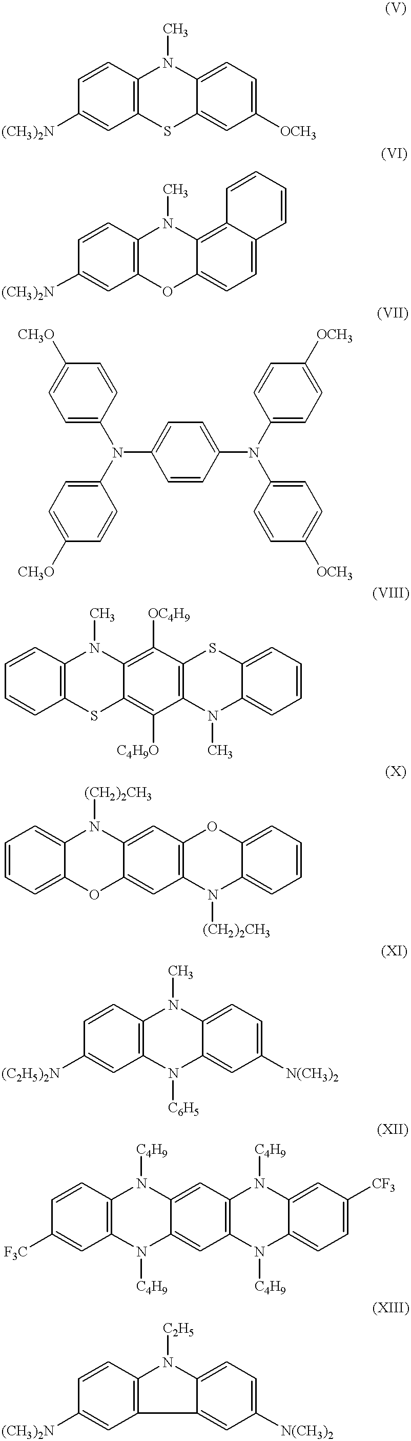


22. An electrochromic device, which comprises, as the medium of reversibly variable transmittance to light, the electrochromic medium of claim 15.
23. An electrochromic device, which comprises, as the medium of reversibly variable transmittance to light, the electrochromic medium of claim 18.
24. The device of claim 23, wherein said electrochromic medium is held in a space defined by two planar, parallel, spaced-apart walls, and a periphery defined by a seal, where the side of each of said walls that is in contact with said medium is coated with a layer of electrically conductive material.
25. An electrochromic medium comprising a crosslinked polymer matrix and at least one anodic compound, where an oxidized form of said anodic compound has a redox potential greater than about 90 mV, and an absorption band having a λmax greater than approximately 750 nm, excluding therefrom the compounds of the formula: 
wherein R51 and R54 are the same or different and are each selected from hydrogen and dialkylamino, wherein the alkyl groups are the same or different and are each of 1 to 6 carbon atoms; R52 is oxygen, sulfur or NR55, wherein R55 is the same as or different from R53 and both R55 and R53 are selected from hydrogen, alkyl of 1 to 10 carbon atoms, phenyl optionally substituted at any one position with chloride, bromide, iodide, cyano, or alkyl of 1 to 4 carbon atoms, or benzyl, optionally substituted at any one position of the phenyl group with chloride, bromide, iodide, cyano, or alkyl of 1 to 4 carbon atoms.
26. The medium of claim 25, wherein said oxidized form of said anodic compound is capable of absorbing in the NIR portion of the electromagnetic spectrum.
27. The medium of claim 25, wherein said medium further comprises a solvent and where said anodic compound is in solution in said solvent and interspersed in said polymer matrix.
28. The medium of claim 27, wherein said medium is self-erasing.
29. The medium of claim 25, wherein the outer product of the SOMO and HDOMO of said anodic compound results in a long axis transition dipole moment.
30. The medium of claim 29, wherein, said oxidized form of said anodic compound is capable of absorbing in the NIR portion of the electromagnetic spectrum and where said electrochromic medium further comprises a solvent and a cathodic electrochromic material.
31. The medium of claim 30, wherein said anodic compound is in solution in said solvent and interspersed in said polymer matrix.
32. The medium of claim 30, wherein said medium is solution-phase.
33. An electrochromic device, which comprises, as the medium of reversibly variable transmittance to light, the electrochromic medium of claim 30.
34. An electrochromic device, which comprises, as the medium of reversibly variable transmittance to light, the electrochromic medium of claim 31.
35. The device of claim 34, wherein said electrochromic medium is held in a space defined by two planar, parallel, spaced-apart walls, and a periphery defined by a seal, where the side of each of said walls that is in contact with said medium is coated with an electrode layer of electrically conductive material, and where said polymer matrix comprises less than about fifty percent by weight of said electrochromic medium.
36. An electrochromic window comprising an electrochromic medium, said electrochromic medium comprising a crosslinked polymer matrix and an anodic compound, wherein said window is capable of absorbing in the NIR portion of the electromagnetic spectrum, and said anodic compound has a redox potential greater than about 90 mV, and an absorption band having a λmax greater than approximately 750 nm, excluding therefrom the compounds of the formula: 
wherein R51 and R54 are the same or different and are each selected from hydrogen and dialkylamino, wherein the alkyl groups are the same or different and are each of 1 to 6 carbon atoms; R52 is oxygen, sulfur or NR55, wherein R55 is the same as or different from R53 and both R55 and R53 are selected from hydrogen, alkyl of 1 to 10 carbon atoms, phenyl optionally substituted at any one position with chloride, bromide, iodide, cyano, or alkyl of 1 to 4 carbon atoms, or benzyl, optionally substituted at any one position of the phenyl group with chloride, bromide, iodide, cyano, or alkyl of 1 to 4 carbon atoms.
37. The window of claim 36, wherein said electrochromic medium further comprises at least one solution-phase anodic compound where an oxidized form of said anodic compound has an ESOMO−EHDOMO of less than 3.6 eV.
38. The window of claim 37, wherein the outer product of the SOMO and HDOMO of said anodic compound results in a long axis transition dipole moment.
39. The window of claim 37, wherein said electrochromic medium is held in a space defined by two planar, parallel, spaced-apart walls, and a periphery defined by a seal, where the side of each said walls that is in contact with said medium is coated with an electrode layer of electrically conductive material.
Priority Applications (6)
| Application Number | Priority Date | Filing Date | Title |
|---|---|---|---|
| US09/034,531 US6193912B1 (en) | 1998-03-03 | 1998-03-03 | Near infrared-absorbing electrochromic compounds and devices comprising same |
| CA002322649A CA2322649C (en) | 1998-03-03 | 1999-03-02 | Near infrared-absorbing electrochromic compounds and devices comprising same |
| DE69925464T DE69925464T2 (en) | 1998-03-03 | 1999-03-02 | IN THE NEAR INFRARED ABSORBENT ELECTROCHROME CONNECTIONS AND DEVICES WITH THE SAME |
| EP99909765A EP1060224B1 (en) | 1998-03-03 | 1999-03-02 | Near infrared-absorbing electrochromic compounds and devices comprising same |
| PCT/US1999/004617 WO1999045081A1 (en) | 1998-03-03 | 1999-03-02 | Near infrared-absorbing electrochromic compounds and devices comprising same |
| AU28897/99A AU754393B2 (en) | 1998-03-03 | 1999-03-02 | Near infrared-absorbing electrochromic compounds and devices comprising same |
Applications Claiming Priority (1)
| Application Number | Priority Date | Filing Date | Title |
|---|---|---|---|
| US09/034,531 US6193912B1 (en) | 1998-03-03 | 1998-03-03 | Near infrared-absorbing electrochromic compounds and devices comprising same |
Publications (1)
| Publication Number | Publication Date |
|---|---|
| US6193912B1 true US6193912B1 (en) | 2001-02-27 |
Family
ID=21876996
Family Applications (1)
| Application Number | Title | Priority Date | Filing Date |
|---|---|---|---|
| US09/034,531 Expired - Lifetime US6193912B1 (en) | 1998-03-03 | 1998-03-03 | Near infrared-absorbing electrochromic compounds and devices comprising same |
Country Status (6)
| Country | Link |
|---|---|
| US (1) | US6193912B1 (en) |
| EP (1) | EP1060224B1 (en) |
| AU (1) | AU754393B2 (en) |
| CA (1) | CA2322649C (en) |
| DE (1) | DE69925464T2 (en) |
| WO (1) | WO1999045081A1 (en) |
Cited By (132)
| Publication number | Priority date | Publication date | Assignee | Title |
|---|---|---|---|---|
| US6327070B1 (en) * | 1998-05-29 | 2001-12-04 | Bayer Aktiengesellschaft | Electrochromic assembly based on poly(3,4-ethylenedioxythiophene) derivatives in combination with a lithium niobate counterelectrode |
| US6392783B1 (en) * | 2000-02-24 | 2002-05-21 | Gentex Corporation | Substituted metallocenes for use as anodic electrochromic materials, and electrochromic media and devices comprising the same |
| US6445486B1 (en) | 1999-12-03 | 2002-09-03 | Gentex Corporation | Electroactive materials and beneficial agents having a solubilizing moiety |
| US6452711B1 (en) * | 1998-05-29 | 2002-09-17 | Bayer Aktiengesellschaft | Electro chromic assembly based on poly (3,4-ethylenedioxythiophene derivatives in the electrochromic layer and the ion-storage layer |
| US20030129368A1 (en) * | 2001-10-26 | 2003-07-10 | Horst Berneth | Electrochromic device and novel electrochromic compounds |
| US6597489B1 (en) * | 1999-06-30 | 2003-07-22 | Gentex Corporation | Electrode design for electrochromic devices |
| WO2003069397A2 (en) | 2001-11-13 | 2003-08-21 | Gentex Corporation | Controlled diffusion coefficient electrochromic materials for use in electrochromic mediums and associated electrochromic devices |
| US6614578B2 (en) | 1999-12-03 | 2003-09-02 | Gentex Corporation | Ultraviolet stabilizing materials having a solublizing moiety |
| US6700693B2 (en) | 1999-12-03 | 2004-03-02 | Gentex Corporation | Electrochromic devices having an electron shuttle |
| WO2004034183A2 (en) | 2002-08-21 | 2004-04-22 | Gentex Corporation | Image acquisition and processing methods for automatic vehicular exterior lighting control |
| US6876479B1 (en) | 2004-05-21 | 2005-04-05 | Gentex Corporation | Tristate electrochromic device |
| US20050078347A1 (en) * | 2003-10-08 | 2005-04-14 | Rongguang Lin | Reversible electrodeposition devices and associated electrochemical media |
| FR2864782A1 (en) * | 2004-01-07 | 2005-07-08 | Oreal | Hair dye composition comprises specific fluorindine compounds used as direct colorants |
| US20050259310A1 (en) * | 2004-05-21 | 2005-11-24 | Gentex Corporation | Tristate electrochromic device |
| US20060103911A1 (en) * | 2004-11-15 | 2006-05-18 | Gentex Corporation | Electrochromic compounds and associated media and devices |
| US7193764B2 (en) | 2003-10-08 | 2007-03-20 | Gentex Corporation | Reversible electrodeposition devices and associated electrochemical media |
| US20070258127A1 (en) * | 2006-05-03 | 2007-11-08 | Gentex Corporation | Controllably dissolving spacing member and associated electrochromic device and method for manufacturing the same |
| US20080316574A1 (en) * | 2004-11-15 | 2008-12-25 | Gentex Corporation | Electrochromic compounds and associated media and devices |
| JP2010034449A (en) * | 2008-07-31 | 2010-02-12 | Mitsui Chemicals Inc | Organic transistor |
| US20100073754A1 (en) * | 2008-09-24 | 2010-03-25 | Gentex Corporation | Ultraviolet light stabilizing compounds and associated media and devices |
| EP2267523A2 (en) | 2004-07-12 | 2010-12-29 | Basf Se | Stabilized electrochromic media |
| US7918570B2 (en) | 2002-06-06 | 2011-04-05 | Donnelly Corporation | Vehicular interior rearview information mirror system |
| EP2322984A1 (en) | 2003-05-06 | 2011-05-18 | Gentex Corporation | Vehicular rearview mirror elements comprising a peripheral light blocking strip |
| US20110176195A1 (en) * | 2007-06-27 | 2011-07-21 | Veenman Steven J | Electrochromic device having an improved fill port plug |
| US7994471B2 (en) | 1998-01-07 | 2011-08-09 | Donnelly Corporation | Interior rearview mirror system with forwardly-viewing camera |
| US8000894B2 (en) | 2000-03-02 | 2011-08-16 | Donnelly Corporation | Vehicular wireless communication system |
| US8019505B2 (en) | 2003-10-14 | 2011-09-13 | Donnelly Corporation | Vehicle information display |
| US20110220097A1 (en) * | 2008-08-11 | 2011-09-15 | Agc Glass Europe | Mirror |
| EP2378350A1 (en) | 2006-03-09 | 2011-10-19 | Gentex Corporation | Vehicle rearview assembly including a high intensity display |
| US8049640B2 (en) | 2003-05-19 | 2011-11-01 | Donnelly Corporation | Mirror assembly for vehicle |
| US8063753B2 (en) | 1997-08-25 | 2011-11-22 | Donnelly Corporation | Interior rearview mirror system |
| US8083386B2 (en) | 2001-01-23 | 2011-12-27 | Donnelly Corporation | Interior rearview mirror assembly with display device |
| US8094002B2 (en) | 1998-01-07 | 2012-01-10 | Donnelly Corporation | Interior rearview mirror system |
| US8100568B2 (en) | 1997-08-25 | 2012-01-24 | Donnelly Corporation | Interior rearview mirror system for a vehicle |
| US8106347B2 (en) | 2002-05-03 | 2012-01-31 | Donnelly Corporation | Vehicle rearview mirror system |
| US8164817B2 (en) | 1994-05-05 | 2012-04-24 | Donnelly Corporation | Method of forming a mirrored bent cut glass shape for vehicular exterior rearview mirror assembly |
| US8162493B2 (en) | 1999-11-24 | 2012-04-24 | Donnelly Corporation | Interior rearview mirror assembly for vehicle |
| US8179586B2 (en) | 2003-10-02 | 2012-05-15 | Donnelly Corporation | Rearview mirror assembly for vehicle |
| US8228588B2 (en) | 2002-09-20 | 2012-07-24 | Donnelly Corporation | Interior rearview mirror information display system for a vehicle |
| US8277059B2 (en) | 2002-09-20 | 2012-10-02 | Donnelly Corporation | Vehicular electrochromic interior rearview mirror assembly |
| US8282226B2 (en) | 2002-06-06 | 2012-10-09 | Donnelly Corporation | Interior rearview mirror system |
| US8288711B2 (en) | 1998-01-07 | 2012-10-16 | Donnelly Corporation | Interior rearview mirror system with forwardly-viewing camera and a control |
| US8335032B2 (en) | 2002-09-20 | 2012-12-18 | Donnelly Corporation | Reflective mirror assembly |
| US8427288B2 (en) | 2000-03-02 | 2013-04-23 | Donnelly Corporation | Rear vision system for a vehicle |
| US20130126792A1 (en) * | 2010-08-05 | 2013-05-23 | Merck Patent Gmbh | Materials for electronic devices |
| US20130128332A1 (en) * | 2009-10-05 | 2013-05-23 | Acreo Ab | Electrochemical device |
| US8503062B2 (en) | 2005-05-16 | 2013-08-06 | Donnelly Corporation | Rearview mirror element assembly for vehicle |
| US8508383B2 (en) | 2008-03-31 | 2013-08-13 | Magna Mirrors of America, Inc | Interior rearview mirror system |
| US8511841B2 (en) | 1994-05-05 | 2013-08-20 | Donnelly Corporation | Vehicular blind spot indicator mirror |
| US8525703B2 (en) | 1998-04-08 | 2013-09-03 | Donnelly Corporation | Interior rearview mirror system |
| US20130284905A1 (en) * | 2012-04-30 | 2013-10-31 | Avery Dennison Corporation | Radio Frequency Identification Sensor Assembly |
| US8610992B2 (en) | 1997-08-25 | 2013-12-17 | Donnelly Corporation | Variable transmission window |
| US8653959B2 (en) | 2001-01-23 | 2014-02-18 | Donnelly Corporation | Video mirror system for a vehicle |
| JP5498795B2 (en) * | 2007-11-12 | 2014-05-21 | 山本化成株式会社 | Organic transistor |
| US8736943B2 (en) | 2012-01-17 | 2014-05-27 | Gentex Corporation | Variable transmission electrochromic window and associated aircraft window system |
| US8867116B1 (en) | 2013-03-15 | 2014-10-21 | Gentex Corporation | Distate electrochromic device |
| US8864322B2 (en) | 2012-08-24 | 2014-10-21 | Gentex Corporation | Shaped rearview mirror assembly |
| US8908039B2 (en) | 2000-03-02 | 2014-12-09 | Donnelly Corporation | Vehicular video mirror system |
| US8928966B1 (en) | 2012-08-08 | 2015-01-06 | Gentex Corporation | Electrochromic polyelectrolyte gel medium having improved creep resistance and associated electrochromic device |
| US9019091B2 (en) | 1999-11-24 | 2015-04-28 | Donnelly Corporation | Interior rearview mirror system |
| US9056584B2 (en) | 2010-07-08 | 2015-06-16 | Gentex Corporation | Rearview assembly for a vehicle |
| US9057925B2 (en) | 2013-03-15 | 2015-06-16 | Gentex Corporation | Fill port plugs for electrochromic devices |
| US9274396B2 (en) | 2010-12-06 | 2016-03-01 | Saint-Gobain Glass France | Electrochemical device having electrically controllable optical and/or energy transmission properties |
| US9316347B2 (en) | 2012-01-24 | 2016-04-19 | Gentex Corporation | Rearview assembly with interchangeable rearward viewing device |
| US9327648B2 (en) | 2013-01-04 | 2016-05-03 | Gentex Corporation | Rearview assembly with exposed carrier plate |
| US9354470B2 (en) | 2013-09-24 | 2016-05-31 | Gentex Corporation | Electro-optic device |
| DE202014010751U1 (en) | 2013-09-24 | 2016-07-18 | Gentex Corporation | Display mirror assembly |
| WO2016145056A1 (en) | 2015-03-09 | 2016-09-15 | Gentex Corporation | Window system with indicia |
| US9488892B2 (en) | 2013-01-09 | 2016-11-08 | Gentex Corporation | Printed appliqué and method thereof |
| US9494839B2 (en) | 2011-04-05 | 2016-11-15 | Acreo Swedish Ict Ab | Electrochemical device manufacturing |
| US9505349B2 (en) | 2012-04-24 | 2016-11-29 | Gentex Corporation | Display mirror assembly |
| USD783480S1 (en) | 2014-12-05 | 2017-04-11 | Gentex Corporation | Rearview device |
| WO2017079144A1 (en) | 2015-11-02 | 2017-05-11 | Gentex Corporation | Display mirror assembly incorporating heatsink |
| WO2017087019A1 (en) | 2015-11-20 | 2017-05-26 | Gentex Corporation | Protic-soluble organic electrochromic compounds |
| WO2017087476A1 (en) | 2015-11-18 | 2017-05-26 | Gentex Corporation | Electro-optic gas barrier |
| US9694752B2 (en) | 2014-11-07 | 2017-07-04 | Gentex Corporation | Full display mirror actuator |
| US9694751B2 (en) | 2014-09-19 | 2017-07-04 | Gentex Corporation | Rearview assembly |
| US9709867B2 (en) | 2010-10-05 | 2017-07-18 | Rise Acreo Ab | Display device |
| US9738140B2 (en) | 2014-08-04 | 2017-08-22 | Gentex Corporation | Electrochromic devices |
| US9766528B2 (en) | 2015-03-09 | 2017-09-19 | Gentex Corporation | Electrochemical devices with plastic substrates |
| US9809171B2 (en) | 2000-03-02 | 2017-11-07 | Magna Electronics Inc. | Vision system for vehicle |
| WO2017192551A1 (en) | 2016-05-03 | 2017-11-09 | Gentex Corporation | Polarized electro-optic element |
| WO2018013941A1 (en) | 2016-07-15 | 2018-01-18 | Gentex Corporation | Second surface transflector for electro-optic device |
| USD809984S1 (en) | 2016-12-07 | 2018-02-13 | Gentex Corporation | Rearview assembly |
| WO2018071180A1 (en) | 2016-10-10 | 2018-04-19 | Gentex Corporation | Polarized window assembly |
| USD817238S1 (en) | 2016-04-29 | 2018-05-08 | Gentex Corporation | Rearview device |
| US9964828B2 (en) | 2014-05-27 | 2018-05-08 | Gentex Corporation | Electrochemical energy storage devices |
| US9978317B2 (en) | 2015-10-09 | 2018-05-22 | Gentex Corporation | Electro-optic mirror having user-adustable dimming with visual feedback |
| US9994156B2 (en) | 2015-10-30 | 2018-06-12 | Gentex Corporation | Rearview device |
| US9995854B2 (en) | 2015-04-20 | 2018-06-12 | Gentex Corporation | Rearview assembly with applique |
| US10025138B2 (en) | 2016-06-06 | 2018-07-17 | Gentex Corporation | Illuminating display with light gathering structure |
| US10029615B2 (en) | 2015-12-14 | 2018-07-24 | Gentex Corporation | Bimodal mechanism with optical switch |
| US10071689B2 (en) | 2014-11-13 | 2018-09-11 | Gentex Corporation | Rearview mirror system with a display |
| US10112540B2 (en) | 2015-05-18 | 2018-10-30 | Gentex Corporation | Full display rearview device |
| WO2018204141A1 (en) | 2017-05-01 | 2018-11-08 | Gentex Corporation | Imaging device with switchable day and night modes |
| US10131279B2 (en) | 2014-12-03 | 2018-11-20 | Gentex Corporation | Display mirror assembly with an RF shield bezel |
| DE212017000117U1 (en) | 2016-04-27 | 2018-12-03 | Gentex Corporation | Vehicle display with focal length correction feature |
| USD845851S1 (en) | 2016-03-31 | 2019-04-16 | Gentex Corporation | Rearview device |
| US10273182B2 (en) | 2012-08-01 | 2019-04-30 | Gentex Corporation | Apparatus, method, and process with laser induced channel edge |
| USD854473S1 (en) | 2016-12-16 | 2019-07-23 | Gentex Corporation | Rearview assembly |
| US10414340B2 (en) | 2013-03-15 | 2019-09-17 | Gentex Corporation | Display system and method thereof |
| EP3540505A2 (en) | 2015-06-25 | 2019-09-18 | Gentex Corporation | Electrochromic thermoplastics, devices, and composites |
| WO2019202556A1 (en) | 2018-04-19 | 2019-10-24 | Gentex Corporation | Plastic coatings for improved solvent resistance |
| US10459307B2 (en) | 2016-04-22 | 2019-10-29 | Gentex Corporation | Flame retardancy of electrochromic devices |
| US10466524B2 (en) | 2004-07-12 | 2019-11-05 | Gentex Corporation | Variable reflectance mirror system |
| WO2019215677A1 (en) | 2018-05-09 | 2019-11-14 | Gentex Corporation | Switchable imager lens cover |
| US10505301B2 (en) | 2015-12-03 | 2019-12-10 | Gentex Corporation | Conductive connection device for vehicle display |
| WO2020056046A1 (en) * | 2018-09-11 | 2020-03-19 | Oregon Health & Science University | Near-infrared nerve-sparing benzo[c]phenoxazine fluorophores |
| WO2020115718A1 (en) | 2018-12-07 | 2020-06-11 | Gentex Corporation | Electro-optic apparatus and seal system |
| WO2020115682A1 (en) | 2018-12-05 | 2020-06-11 | Gentex Corporation | Imaging system for iris authentication and driver monitoring |
| US10685623B2 (en) | 2015-10-30 | 2020-06-16 | Gentex Corporation | Toggle paddle |
| WO2020121174A1 (en) | 2018-12-10 | 2020-06-18 | Gentex Corporation | Scanning apparatus for reducing field of view search space |
| US10733437B2 (en) | 2017-03-22 | 2020-08-04 | Gentex Corporation | Display assembly incorporating an image sensor |
| US10739661B2 (en) | 2017-09-25 | 2020-08-11 | Gentex Corporation | IR transmitting coating for electro-optic element |
| US10769434B2 (en) | 2015-12-22 | 2020-09-08 | Gentex Corporation | Mirror assembly incorporating a scanning apparatus |
| US10766422B2 (en) | 2015-12-11 | 2020-09-08 | Gentex Corporation | IR transmitting coating for electro-optic element |
| US10781364B2 (en) | 2016-10-20 | 2020-09-22 | Gentex Corporation | Electrochromic media and devices with multiple color states |
| US10800335B2 (en) | 2015-09-18 | 2020-10-13 | Gentex Corporation | Toggle mechanism for rearview assembly |
| US10824860B2 (en) | 2018-07-12 | 2020-11-03 | Gentex Corporation | Mirror assembly incorporating a scanning apparatus |
| US10929698B2 (en) | 2018-12-17 | 2021-02-23 | Gentex Corporation | Advanced features for vehicle authentication system |
| EP3800502A1 (en) | 2019-10-01 | 2021-04-07 | Acondicionamiento Tarrasense | Thermo-responsive dual band electrochromic device |
| US11029519B2 (en) | 2016-10-21 | 2021-06-08 | Gentex Corporation | Antireflection coatings |
| US11066046B2 (en) | 2018-09-25 | 2021-07-20 | Getex Corporation | Authentication concealment and alignment systems |
| US11092867B2 (en) | 2017-12-29 | 2021-08-17 | Gentex Corporation | Polarized electrochromic device |
| WO2021163235A1 (en) | 2020-02-11 | 2021-08-19 | Gentex Corporation | Rearview device |
| US11305621B2 (en) | 2018-11-26 | 2022-04-19 | Gentex Corporation | Vehicle display system with reflection control |
| US20220308417A1 (en) * | 2017-05-17 | 2022-09-29 | University Of South Florida | Single active layer electrochromic devices |
| US11468710B2 (en) | 2018-12-13 | 2022-10-11 | Gentex Corporation | Alignment apparatus for vehicle authentication system |
| US11479185B2 (en) | 2019-02-01 | 2022-10-25 | Gentex Corporation | Active infrared illumination for enhancing rear vision from a vehicle |
| DE212021000467U1 (en) | 2020-09-18 | 2023-06-14 | Gentex Corporation | Masking plate with asymmetric reflectance |
| WO2023205262A1 (en) * | 2022-04-20 | 2023-10-26 | Gentex Corporation | Electrochromic devices having a buffer system |
| US11906866B2 (en) | 2019-06-27 | 2024-02-20 | Gentex Corporation | Electrochromic films and methods of forming and using |
Families Citing this family (8)
| Publication number | Priority date | Publication date | Assignee | Title |
|---|---|---|---|---|
| US6891563B2 (en) | 1996-05-22 | 2005-05-10 | Donnelly Corporation | Vehicular vision system |
| US6266177B1 (en) | 1999-11-18 | 2001-07-24 | Donnelly Corporation | Electrochromic devices |
| US7450292B1 (en) | 2003-06-20 | 2008-11-11 | Los Alamos National Security, Llc | Durable electrooptic devices comprising ionic liquids |
| US7300166B2 (en) | 2003-03-05 | 2007-11-27 | Electrochromix, Inc. | Electrochromic mirrors and other electrooptic devices |
| KR20110116618A (en) * | 2010-04-20 | 2011-10-26 | 다우어드밴스드디스플레이머티리얼 유한회사 | Novel organic electroluminescent compounds and organic electroluminescent device using the same |
| CN105348301A (en) * | 2015-11-25 | 2016-02-24 | 武汉工程大学 | Phenothiazines intermediate and preparation method therefor |
| US10954201B2 (en) * | 2016-08-23 | 2021-03-23 | University Of Kentucky Research Foundation | Two-electron donating phenothiazines and use thereof |
| JP6824425B2 (en) * | 2016-10-17 | 2021-02-03 | ジェンテックス コーポレイション | Near-infrared absorbing compounds and devices incorporating them |
Citations (13)
| Publication number | Priority date | Publication date | Assignee | Title |
|---|---|---|---|---|
| US3341464A (en) | 1962-08-09 | 1967-09-12 | American Cyanamid Co | Heat resistant aminium salt infrared absorbers |
| SU830456A1 (en) | 1979-04-09 | 1981-05-15 | Всесоюзный Научно-Исследователь-Ский Конструкторско-Техноло-Гический Институт По Машинам Длякомплексной Механизации Иавтоматизации Животноводческихферм | Device for emergency signalling of electric motor switching off |
| US4402573A (en) | 1981-06-18 | 1983-09-06 | International Business Machines Corporation | Materials for electrochromic display devices |
| JPS6350883A (en) | 1986-08-21 | 1988-03-03 | 富士通株式会社 | Partition integer excess calculator |
| US4902108A (en) | 1986-03-31 | 1990-02-20 | Gentex Corporation | Single-compartment, self-erasing, solution-phase electrochromic devices, solutions for use therein, and uses thereof |
| US5140455A (en) | 1989-11-29 | 1992-08-18 | Donnelly Corporation | High performance electrochemichromic solutions and devices thereof |
| US5145609A (en) * | 1990-11-07 | 1992-09-08 | Donnelly Corporation | Linear polyether-containing electrochemichromic solutions and related devices |
| US5239406A (en) | 1988-02-12 | 1993-08-24 | Donnelly Corporation | Near-infrared reflecting, ultraviolet protected, safety protected, electrochromic vehicular glazing |
| EP0612826A1 (en) | 1993-02-26 | 1994-08-31 | Donnelly Corporation | Electrochromic polymeric solid films, manufacturing electrochromic devices using such solid films, and processing for making such solid films and devices |
| WO1994023333A1 (en) | 1993-04-05 | 1994-10-13 | Igen, Inc. | Complementary surface confined polymer electrochromic materials, systems, and methods of fabrication therefor |
| WO1996003475A1 (en) | 1994-07-22 | 1996-02-08 | Gentex Corporation | Electrochromic layer and devices comprising same |
| WO1997030134A1 (en) | 1996-02-15 | 1997-08-21 | Bayer Aktiengesellschaft | Electrochromic system |
| US5928572A (en) * | 1996-03-15 | 1999-07-27 | Gentex Corporation | Electrochromic layer and devices comprising same |
-
1998
- 1998-03-03 US US09/034,531 patent/US6193912B1/en not_active Expired - Lifetime
-
1999
- 1999-03-02 DE DE69925464T patent/DE69925464T2/en not_active Expired - Lifetime
- 1999-03-02 AU AU28897/99A patent/AU754393B2/en not_active Expired
- 1999-03-02 WO PCT/US1999/004617 patent/WO1999045081A1/en active IP Right Grant
- 1999-03-02 EP EP99909765A patent/EP1060224B1/en not_active Expired - Lifetime
- 1999-03-02 CA CA002322649A patent/CA2322649C/en not_active Expired - Lifetime
Patent Citations (14)
| Publication number | Priority date | Publication date | Assignee | Title |
|---|---|---|---|---|
| US3341464A (en) | 1962-08-09 | 1967-09-12 | American Cyanamid Co | Heat resistant aminium salt infrared absorbers |
| SU830456A1 (en) | 1979-04-09 | 1981-05-15 | Всесоюзный Научно-Исследователь-Ский Конструкторско-Техноло-Гический Институт По Машинам Длякомплексной Механизации Иавтоматизации Животноводческихферм | Device for emergency signalling of electric motor switching off |
| US4402573A (en) | 1981-06-18 | 1983-09-06 | International Business Machines Corporation | Materials for electrochromic display devices |
| US4902108A (en) | 1986-03-31 | 1990-02-20 | Gentex Corporation | Single-compartment, self-erasing, solution-phase electrochromic devices, solutions for use therein, and uses thereof |
| JPS6350883A (en) | 1986-08-21 | 1988-03-03 | 富士通株式会社 | Partition integer excess calculator |
| US5239406A (en) | 1988-02-12 | 1993-08-24 | Donnelly Corporation | Near-infrared reflecting, ultraviolet protected, safety protected, electrochromic vehicular glazing |
| US5140455A (en) | 1989-11-29 | 1992-08-18 | Donnelly Corporation | High performance electrochemichromic solutions and devices thereof |
| US5145609A (en) * | 1990-11-07 | 1992-09-08 | Donnelly Corporation | Linear polyether-containing electrochemichromic solutions and related devices |
| EP0612826A1 (en) | 1993-02-26 | 1994-08-31 | Donnelly Corporation | Electrochromic polymeric solid films, manufacturing electrochromic devices using such solid films, and processing for making such solid films and devices |
| WO1994023333A1 (en) | 1993-04-05 | 1994-10-13 | Igen, Inc. | Complementary surface confined polymer electrochromic materials, systems, and methods of fabrication therefor |
| WO1996003475A1 (en) | 1994-07-22 | 1996-02-08 | Gentex Corporation | Electrochromic layer and devices comprising same |
| US5679283A (en) * | 1994-07-22 | 1997-10-21 | Gentex Corporation | Electrochromic layer and devices comprising same |
| WO1997030134A1 (en) | 1996-02-15 | 1997-08-21 | Bayer Aktiengesellschaft | Electrochromic system |
| US5928572A (en) * | 1996-03-15 | 1999-07-27 | Gentex Corporation | Electrochromic layer and devices comprising same |
Non-Patent Citations (19)
| Title |
|---|
| A. Yasuda et al., An Electrochromic Display Using Viologen-Cyclodextrin Inclusion Complex, (Session 4-ECDs and Other Technology, Japan Display '86), 1986). |
| G. A. Sotzing et al., Multiply Colored Electrochromic Carbaxole-Based Polymers, Chem. Mater. 1997,9,1578-1587. |
| H. Yamamoto et al., A Multicolor Electrochromic Display Using Phthalocyanine Films with Solid Electrolyte, (Session 4-ECDs and Other Technology, Japan Display '86), (1986). |
| Habib, MA., Electrochemistry in Transition, 1992, pp. 51-62. |
| J. Guay et al., Electrooxidation of Soluble alpha-alpha -Coupled Thiophene Oligomers, Chem. Mater. 1992, 4, 254-255. |
| J. Guay et al., Electrooxidation of Soluble α-α -Coupled Thiophene Oligomers, Chem. Mater. 1992, 4, 254-255. |
| J. Stepp et al., Electrochromism and Electrocatalysis in Viologen Polyelectrolyte Multilayers, J. Electrochem. Soc., vol. 144, No. 6, 1997, pp. L155-L157. |
| K. Lahlil et al., Intervalence Transitions In Mixed Valence Bis(tetrathiofulvalene) Compounds, J. Am. Chem. Soc. 1995, 117, 9995-10002. |
| M. K. Carpenter et al., A Single-Film Electrochromic Devices, J. Electrochem. Soc., vol. 137, No. 8, 1990, pp. 2464-2467. |
| Masaoski, F. et al., Photoreduction of Bisviologen Compounds, Viologen-(CH2)n-Viologen, by 2-propanol, Bull. Chem. Soc. Jpn. vol. 55, No. 2, 513-516, (1982). |
| N. Baba, et al., An Electrochemical Method of Preparing IrOx Thin Films and SnO2Electrodes, (Session 4-ECDs and Other Technology, Japan Display '86, (1986). |
| N. Leventis, Polymers in Electrochromics, Polymer News, 1995, vol.20, pp. 5-18. |
| O. Takai., A New Electrochromic System Using Tin Nitride Thin Films, (Session 4-ECDs and Other Technology, Japan Display '86), (1986). |
| S. A. Sapp et al., Rapid Switching In Electrochromic Devices Based On Complementary Conducting Polymer Films, ACS New Orleans, Spring 1996, Polymer Preprint. |
| S. Hunig et al., Conjugated Radicals IX, Experimental Study of the LCI SCF Open Shell Calculations on the Electronic Spectra and the Redox Equilibria of the Nitrogen-Containing Violenes, The Journal of Physical Chemistry, vol. 75, No. 3, 1971, pp. 335-339. |
| S. Kuwabata, et al., Redox Behavior and Electrochromic Properties of Polypyrrole Films in Aquious Solutions, Bull. Chem. Soc. Jpn., vol. 57, No.8, 1984, pp. 2247-2253. |
| V. M. Domingo et al., Inert Carbon Free Radicals. 14. Synthesis, Isolation and Properties of Two Strongly Π—Π Interacting Mixed-Valence Compounds: The Perchloro-4,4′-ethynylenebis(triphenylmethyl) Anion Radical Potassium (18-Crown-6) Salt and the Perchloro-α-α-α′-α′-tetraphenyl-p-xylene Anion Radical Tetrabutylammonium Salt, Chem. Mater. 1997, 9, 1620-1629. |
| V. M. Domingo et al., Inert Carbon Free Radicals. 14. Synthesis, Isolation and Properties of Two Strongly Π-Π Interacting Mixed-Valence Compounds: The Perchloro-4,4'-ethynylenebis(triphenylmethyl) Anion Radical Potassium (18-Crown-6) Salt and the Perchloro-alpha-alpha-alpha'-alpha'-tetraphenyl-p-xylene Anion Radical Tetrabutylammonium Salt, Chem. Mater. 1997, 9, 1620-1629. |
| Yuan Yu et al., Spectra and Reactivly of MeThoxyoligothiophene Cation Radicals, J. Am. Chem. Soc. 1996, vol. 118, No. 5, 1013-1018. |
Cited By (274)
| Publication number | Priority date | Publication date | Assignee | Title |
|---|---|---|---|---|
| US8511841B2 (en) | 1994-05-05 | 2013-08-20 | Donnelly Corporation | Vehicular blind spot indicator mirror |
| US8164817B2 (en) | 1994-05-05 | 2012-04-24 | Donnelly Corporation | Method of forming a mirrored bent cut glass shape for vehicular exterior rearview mirror assembly |
| US8559093B2 (en) | 1995-04-27 | 2013-10-15 | Donnelly Corporation | Electrochromic mirror reflective element for vehicular rearview mirror assembly |
| US8100568B2 (en) | 1997-08-25 | 2012-01-24 | Donnelly Corporation | Interior rearview mirror system for a vehicle |
| US8063753B2 (en) | 1997-08-25 | 2011-11-22 | Donnelly Corporation | Interior rearview mirror system |
| US8610992B2 (en) | 1997-08-25 | 2013-12-17 | Donnelly Corporation | Variable transmission window |
| US8779910B2 (en) | 1997-08-25 | 2014-07-15 | Donnelly Corporation | Interior rearview mirror system |
| US8267559B2 (en) | 1997-08-25 | 2012-09-18 | Donnelly Corporation | Interior rearview mirror assembly for a vehicle |
| US8094002B2 (en) | 1998-01-07 | 2012-01-10 | Donnelly Corporation | Interior rearview mirror system |
| US8288711B2 (en) | 1998-01-07 | 2012-10-16 | Donnelly Corporation | Interior rearview mirror system with forwardly-viewing camera and a control |
| US8134117B2 (en) | 1998-01-07 | 2012-03-13 | Donnelly Corporation | Vehicular having a camera, a rain sensor and a single-ball interior electrochromic mirror assembly attached at an attachment element |
| US7994471B2 (en) | 1998-01-07 | 2011-08-09 | Donnelly Corporation | Interior rearview mirror system with forwardly-viewing camera |
| US8325028B2 (en) | 1998-01-07 | 2012-12-04 | Donnelly Corporation | Interior rearview mirror system |
| US9221399B2 (en) | 1998-04-08 | 2015-12-29 | Magna Mirrors Of America, Inc. | Automotive communication system |
| US9481306B2 (en) | 1998-04-08 | 2016-11-01 | Donnelly Corporation | Automotive communication system |
| US8884788B2 (en) | 1998-04-08 | 2014-11-11 | Donnelly Corporation | Automotive communication system |
| US8525703B2 (en) | 1998-04-08 | 2013-09-03 | Donnelly Corporation | Interior rearview mirror system |
| US6327070B1 (en) * | 1998-05-29 | 2001-12-04 | Bayer Aktiengesellschaft | Electrochromic assembly based on poly(3,4-ethylenedioxythiophene) derivatives in combination with a lithium niobate counterelectrode |
| US6452711B1 (en) * | 1998-05-29 | 2002-09-17 | Bayer Aktiengesellschaft | Electro chromic assembly based on poly (3,4-ethylenedioxythiophene derivatives in the electrochromic layer and the ion-storage layer |
| US6606184B2 (en) | 1999-06-30 | 2003-08-12 | Gentex Corporation | Electrode design for electrochromic devices |
| US6597489B1 (en) * | 1999-06-30 | 2003-07-22 | Gentex Corporation | Electrode design for electrochromic devices |
| US10144355B2 (en) | 1999-11-24 | 2018-12-04 | Donnelly Corporation | Interior rearview mirror system for vehicle |
| US8162493B2 (en) | 1999-11-24 | 2012-04-24 | Donnelly Corporation | Interior rearview mirror assembly for vehicle |
| US9376061B2 (en) | 1999-11-24 | 2016-06-28 | Donnelly Corporation | Accessory system of a vehicle |
| US9278654B2 (en) | 1999-11-24 | 2016-03-08 | Donnelly Corporation | Interior rearview mirror system for vehicle |
| US9019091B2 (en) | 1999-11-24 | 2015-04-28 | Donnelly Corporation | Interior rearview mirror system |
| US6710906B2 (en) | 1999-12-03 | 2004-03-23 | Gentex Corporation | Controlled diffusion coefficient electrochromic materials for use in electrochromic mediums and associated electrochromic devices |
| US6700693B2 (en) | 1999-12-03 | 2004-03-02 | Gentex Corporation | Electrochromic devices having an electron shuttle |
| US20040233500A1 (en) * | 1999-12-03 | 2004-11-25 | Roberts Kathy E. | Electrochromic devices having an electron shuttle |
| US6614578B2 (en) | 1999-12-03 | 2003-09-02 | Gentex Corporation | Ultraviolet stabilizing materials having a solublizing moiety |
| US7031043B2 (en) | 1999-12-03 | 2006-04-18 | Gentex Corporation | Electrochromic devices having an electron shuttle |
| US6496294B2 (en) | 1999-12-03 | 2002-12-17 | Gentex Corporation | Anodic electroactive materials having a solublizing moiety |
| US6445486B1 (en) | 1999-12-03 | 2002-09-03 | Gentex Corporation | Electroactive materials and beneficial agents having a solubilizing moiety |
| US6594066B2 (en) | 2000-02-24 | 2003-07-15 | Gentex Corporation | Substituted metallocenes and electrochromic media and devices comprising the same |
| US6392783B1 (en) * | 2000-02-24 | 2002-05-21 | Gentex Corporation | Substituted metallocenes for use as anodic electrochromic materials, and electrochromic media and devices comprising the same |
| US8543330B2 (en) | 2000-03-02 | 2013-09-24 | Donnelly Corporation | Driver assist system for vehicle |
| US9783114B2 (en) | 2000-03-02 | 2017-10-10 | Donnelly Corporation | Vehicular video mirror system |
| US9315151B2 (en) | 2000-03-02 | 2016-04-19 | Magna Electronics Inc. | Driver assist system for vehicle |
| US8427288B2 (en) | 2000-03-02 | 2013-04-23 | Donnelly Corporation | Rear vision system for a vehicle |
| US8271187B2 (en) | 2000-03-02 | 2012-09-18 | Donnelly Corporation | Vehicular video mirror system |
| US10131280B2 (en) | 2000-03-02 | 2018-11-20 | Donnelly Corporation | Vehicular video mirror system |
| US10053013B2 (en) | 2000-03-02 | 2018-08-21 | Magna Electronics Inc. | Vision system for vehicle |
| US8121787B2 (en) | 2000-03-02 | 2012-02-21 | Donnelly Corporation | Vehicular video mirror system |
| US8676491B2 (en) | 2000-03-02 | 2014-03-18 | Magna Electronics Inc. | Driver assist system for vehicle |
| US9014966B2 (en) | 2000-03-02 | 2015-04-21 | Magna Electronics Inc. | Driver assist system for vehicle |
| US9809171B2 (en) | 2000-03-02 | 2017-11-07 | Magna Electronics Inc. | Vision system for vehicle |
| US8908039B2 (en) | 2000-03-02 | 2014-12-09 | Donnelly Corporation | Vehicular video mirror system |
| US8000894B2 (en) | 2000-03-02 | 2011-08-16 | Donnelly Corporation | Vehicular wireless communication system |
| US9809168B2 (en) | 2000-03-02 | 2017-11-07 | Magna Electronics Inc. | Driver assist system for vehicle |
| US10239457B2 (en) | 2000-03-02 | 2019-03-26 | Magna Electronics Inc. | Vehicular vision system |
| US10179545B2 (en) | 2000-03-02 | 2019-01-15 | Magna Electronics Inc. | Park-aid system for vehicle |
| US9694749B2 (en) | 2001-01-23 | 2017-07-04 | Magna Electronics Inc. | Trailer hitching aid system for vehicle |
| US8653959B2 (en) | 2001-01-23 | 2014-02-18 | Donnelly Corporation | Video mirror system for a vehicle |
| US9352623B2 (en) | 2001-01-23 | 2016-05-31 | Magna Electronics Inc. | Trailer hitching aid system for vehicle |
| US8083386B2 (en) | 2001-01-23 | 2011-12-27 | Donnelly Corporation | Interior rearview mirror assembly with display device |
| US8654433B2 (en) | 2001-01-23 | 2014-02-18 | Magna Mirrors Of America, Inc. | Rearview mirror assembly for vehicle |
| US10272839B2 (en) | 2001-01-23 | 2019-04-30 | Magna Electronics Inc. | Rear seat occupant monitoring system for vehicle |
| US20030129368A1 (en) * | 2001-10-26 | 2003-07-10 | Horst Berneth | Electrochromic device and novel electrochromic compounds |
| US6806989B2 (en) * | 2001-10-26 | 2004-10-19 | Bayer Aktiengesellschaft | Electrochromic device and novel electrochromic compounds |
| WO2003069397A2 (en) | 2001-11-13 | 2003-08-21 | Gentex Corporation | Controlled diffusion coefficient electrochromic materials for use in electrochromic mediums and associated electrochromic devices |
| US8106347B2 (en) | 2002-05-03 | 2012-01-31 | Donnelly Corporation | Vehicle rearview mirror system |
| US8304711B2 (en) | 2002-05-03 | 2012-11-06 | Donnelly Corporation | Vehicle rearview mirror system |
| US8465162B2 (en) | 2002-06-06 | 2013-06-18 | Donnelly Corporation | Vehicular interior rearview mirror system |
| US8465163B2 (en) | 2002-06-06 | 2013-06-18 | Donnelly Corporation | Interior rearview mirror system |
| US8177376B2 (en) | 2002-06-06 | 2012-05-15 | Donnelly Corporation | Vehicular interior rearview mirror system |
| US7918570B2 (en) | 2002-06-06 | 2011-04-05 | Donnelly Corporation | Vehicular interior rearview information mirror system |
| US8608327B2 (en) | 2002-06-06 | 2013-12-17 | Donnelly Corporation | Automatic compass system for vehicle |
| US8047667B2 (en) | 2002-06-06 | 2011-11-01 | Donnelly Corporation | Vehicular interior rearview mirror system |
| US8282226B2 (en) | 2002-06-06 | 2012-10-09 | Donnelly Corporation | Interior rearview mirror system |
| WO2004013688A1 (en) | 2002-08-02 | 2004-02-12 | Gentex Corporation | Holographic surface mask etching and optical strucdtures |
| WO2004034183A2 (en) | 2002-08-21 | 2004-04-22 | Gentex Corporation | Image acquisition and processing methods for automatic vehicular exterior lighting control |
| US8400704B2 (en) | 2002-09-20 | 2013-03-19 | Donnelly Corporation | Interior rearview mirror system for a vehicle |
| US9545883B2 (en) | 2002-09-20 | 2017-01-17 | Donnelly Corporation | Exterior rearview mirror assembly |
| US10363875B2 (en) | 2002-09-20 | 2019-07-30 | Donnelly Corportion | Vehicular exterior electrically variable reflectance mirror reflective element assembly |
| US9341914B2 (en) | 2002-09-20 | 2016-05-17 | Donnelly Corporation | Variable reflectance mirror reflective element for exterior mirror assembly |
| US9090211B2 (en) | 2002-09-20 | 2015-07-28 | Donnelly Corporation | Variable reflectance mirror reflective element for exterior mirror assembly |
| US8335032B2 (en) | 2002-09-20 | 2012-12-18 | Donnelly Corporation | Reflective mirror assembly |
| US9073491B2 (en) | 2002-09-20 | 2015-07-07 | Donnelly Corporation | Exterior rearview mirror assembly |
| US10538202B2 (en) | 2002-09-20 | 2020-01-21 | Donnelly Corporation | Method of manufacturing variable reflectance mirror reflective element for exterior mirror assembly |
| US10029616B2 (en) | 2002-09-20 | 2018-07-24 | Donnelly Corporation | Rearview mirror assembly for vehicle |
| US8506096B2 (en) | 2002-09-20 | 2013-08-13 | Donnelly Corporation | Variable reflectance mirror reflective element for exterior mirror assembly |
| US8277059B2 (en) | 2002-09-20 | 2012-10-02 | Donnelly Corporation | Vehicular electrochromic interior rearview mirror assembly |
| US10661716B2 (en) | 2002-09-20 | 2020-05-26 | Donnelly Corporation | Vehicular exterior electrically variable reflectance mirror reflective element assembly |
| US8797627B2 (en) | 2002-09-20 | 2014-08-05 | Donnelly Corporation | Exterior rearview mirror assembly |
| US8228588B2 (en) | 2002-09-20 | 2012-07-24 | Donnelly Corporation | Interior rearview mirror information display system for a vehicle |
| US9878670B2 (en) | 2002-09-20 | 2018-01-30 | Donnelly Corporation | Variable reflectance mirror reflective element for exterior mirror assembly |
| US8727547B2 (en) | 2002-09-20 | 2014-05-20 | Donnelly Corporation | Variable reflectance mirror reflective element for exterior mirror assembly |
| EP2322984A1 (en) | 2003-05-06 | 2011-05-18 | Gentex Corporation | Vehicular rearview mirror elements comprising a peripheral light blocking strip |
| US9557584B2 (en) | 2003-05-19 | 2017-01-31 | Donnelly Corporation | Rearview mirror assembly for vehicle |
| US11433816B2 (en) | 2003-05-19 | 2022-09-06 | Magna Mirrors Of America, Inc. | Vehicular interior rearview mirror assembly with cap portion |
| US10449903B2 (en) | 2003-05-19 | 2019-10-22 | Donnelly Corporation | Rearview mirror assembly for vehicle |
| US8325055B2 (en) | 2003-05-19 | 2012-12-04 | Donnelly Corporation | Mirror assembly for vehicle |
| US10166927B2 (en) | 2003-05-19 | 2019-01-01 | Donnelly Corporation | Rearview mirror assembly for vehicle |
| US8049640B2 (en) | 2003-05-19 | 2011-11-01 | Donnelly Corporation | Mirror assembly for vehicle |
| US8508384B2 (en) | 2003-05-19 | 2013-08-13 | Donnelly Corporation | Rearview mirror assembly for vehicle |
| US9783115B2 (en) | 2003-05-19 | 2017-10-10 | Donnelly Corporation | Rearview mirror assembly for vehicle |
| US10829052B2 (en) | 2003-05-19 | 2020-11-10 | Donnelly Corporation | Rearview mirror assembly for vehicle |
| US8379289B2 (en) | 2003-10-02 | 2013-02-19 | Donnelly Corporation | Rearview mirror assembly for vehicle |
| US8705161B2 (en) | 2003-10-02 | 2014-04-22 | Donnelly Corporation | Method of manufacturing a reflective element for a vehicular rearview mirror assembly |
| US8179586B2 (en) | 2003-10-02 | 2012-05-15 | Donnelly Corporation | Rearview mirror assembly for vehicle |
| US20070195398A1 (en) * | 2003-10-08 | 2007-08-23 | Rongguang Lin | Reversible electrodeposition devices and associated electrochemical media |
| US20050078347A1 (en) * | 2003-10-08 | 2005-04-14 | Rongguang Lin | Reversible electrodeposition devices and associated electrochemical media |
| US7508568B2 (en) | 2003-10-08 | 2009-03-24 | Gentex Corporation | Reversible electrodeposition devices and associated electrochemical media |
| US7046418B2 (en) | 2003-10-08 | 2006-05-16 | Gentex Corporation | Reversible electrodeposition devices and associated electrochemical media |
| US7193764B2 (en) | 2003-10-08 | 2007-03-20 | Gentex Corporation | Reversible electrodeposition devices and associated electrochemical media |
| US8095260B1 (en) | 2003-10-14 | 2012-01-10 | Donnelly Corporation | Vehicle information display |
| US8019505B2 (en) | 2003-10-14 | 2011-09-13 | Donnelly Corporation | Vehicle information display |
| US8170748B1 (en) | 2003-10-14 | 2012-05-01 | Donnelly Corporation | Vehicle information display system |
| US8577549B2 (en) | 2003-10-14 | 2013-11-05 | Donnelly Corporation | Information display system for a vehicle |
| US8355839B2 (en) | 2003-10-14 | 2013-01-15 | Donnelly Corporation | Vehicle vision system with night vision function |
| FR2864782A1 (en) * | 2004-01-07 | 2005-07-08 | Oreal | Hair dye composition comprises specific fluorindine compounds used as direct colorants |
| EP1552813A1 (en) * | 2004-01-07 | 2005-07-13 | L'oreal | Hair dyeing composition comprising a fluorindinium compound. |
| US6876479B1 (en) | 2004-05-21 | 2005-04-05 | Gentex Corporation | Tristate electrochromic device |
| US20050259310A1 (en) * | 2004-05-21 | 2005-11-24 | Gentex Corporation | Tristate electrochromic device |
| EP1747495A1 (en) * | 2004-05-21 | 2007-01-31 | Gentex Corporation | Tristate electrochromic device |
| EP1747495B1 (en) * | 2004-05-21 | 2016-11-30 | Gentex Corporation | Tristate electrochromic device |
| US20060023290A1 (en) * | 2004-05-21 | 2006-02-02 | Gentex Corporation | Tristate electrochromic device |
| US7835059B2 (en) | 2004-05-21 | 2010-11-16 | Gentex Corporation | Tristate electrochromic device |
| EP2267523A2 (en) | 2004-07-12 | 2010-12-29 | Basf Se | Stabilized electrochromic media |
| US10466524B2 (en) | 2004-07-12 | 2019-11-05 | Gentex Corporation | Variable reflectance mirror system |
| US7855821B2 (en) | 2004-11-15 | 2010-12-21 | Gentex Corporation | Electrochromic compounds and associated media and devices |
| US7428091B2 (en) | 2004-11-15 | 2008-09-23 | Gentex Corporation | Electrochromic compounds and associated media and devices |
| US20060103911A1 (en) * | 2004-11-15 | 2006-05-18 | Gentex Corporation | Electrochromic compounds and associated media and devices |
| US20080316574A1 (en) * | 2004-11-15 | 2008-12-25 | Gentex Corporation | Electrochromic compounds and associated media and devices |
| US8282253B2 (en) | 2004-11-22 | 2012-10-09 | Donnelly Corporation | Mirror reflective element sub-assembly for exterior rearview mirror of a vehicle |
| US8503062B2 (en) | 2005-05-16 | 2013-08-06 | Donnelly Corporation | Rearview mirror element assembly for vehicle |
| US10308186B2 (en) | 2005-09-14 | 2019-06-04 | Magna Mirrors Of America, Inc. | Vehicular exterior rearview mirror assembly with blind spot indicator |
| US10150417B2 (en) | 2005-09-14 | 2018-12-11 | Magna Mirrors Of America, Inc. | Mirror reflective element sub-assembly for exterior rearview mirror of a vehicle |
| US9758102B1 (en) | 2005-09-14 | 2017-09-12 | Magna Mirrors Of America, Inc. | Mirror reflective element sub-assembly for exterior rearview mirror of a vehicle |
| US8833987B2 (en) | 2005-09-14 | 2014-09-16 | Donnelly Corporation | Mirror reflective element sub-assembly for exterior rearview mirror of a vehicle |
| US9045091B2 (en) | 2005-09-14 | 2015-06-02 | Donnelly Corporation | Mirror reflective element sub-assembly for exterior rearview mirror of a vehicle |
| US9694753B2 (en) | 2005-09-14 | 2017-07-04 | Magna Mirrors Of America, Inc. | Mirror reflective element sub-assembly for exterior rearview mirror of a vehicle |
| US11072288B2 (en) | 2005-09-14 | 2021-07-27 | Magna Mirrors Of America, Inc. | Vehicular exterior rearview mirror assembly with blind spot indicator element |
| US10829053B2 (en) | 2005-09-14 | 2020-11-10 | Magna Mirrors Of America, Inc. | Vehicular exterior rearview mirror assembly with blind spot indicator |
| US11285879B2 (en) | 2005-09-14 | 2022-03-29 | Magna Mirrors Of America, Inc. | Vehicular exterior rearview mirror assembly with blind spot indicator element |
| US11124121B2 (en) | 2005-11-01 | 2021-09-21 | Magna Electronics Inc. | Vehicular vision system |
| EP2378350A1 (en) | 2006-03-09 | 2011-10-19 | Gentex Corporation | Vehicle rearview assembly including a high intensity display |
| US20070258127A1 (en) * | 2006-05-03 | 2007-11-08 | Gentex Corporation | Controllably dissolving spacing member and associated electrochromic device and method for manufacturing the same |
| US7684103B2 (en) | 2006-05-03 | 2010-03-23 | Gentex Corporation | Controllably dissolving spacing member and associated electrochromic device and method for manufacturing the same |
| US20090027756A1 (en) * | 2006-05-03 | 2009-01-29 | Ash Kevin L | Controllably dissolving spacing member and associated electrochromic device and method for manufacturing the same |
| US7414770B2 (en) | 2006-05-03 | 2008-08-19 | Gentex Corporation | Contollably dissolving spacing member and associated electrochromic device and method for manufacturing the same |
| US20110176195A1 (en) * | 2007-06-27 | 2011-07-21 | Veenman Steven J | Electrochromic device having an improved fill port plug |
| US9128345B2 (en) | 2007-06-27 | 2015-09-08 | Gentex Corporation | Electrochromic device having an improved fill port plug |
| US8345345B2 (en) | 2007-06-27 | 2013-01-01 | Gentex Corporation | Electrochromic device having an improved fill port plug |
| US8891154B2 (en) | 2007-06-27 | 2014-11-18 | Gentex Corporation | Electrochromic device having an improved fill port plug |
| JP5498795B2 (en) * | 2007-11-12 | 2014-05-21 | 山本化成株式会社 | Organic transistor |
| US8508383B2 (en) | 2008-03-31 | 2013-08-13 | Magna Mirrors of America, Inc | Interior rearview mirror system |
| US10175477B2 (en) | 2008-03-31 | 2019-01-08 | Magna Mirrors Of America, Inc. | Display system for vehicle |
| JP2010034449A (en) * | 2008-07-31 | 2010-02-12 | Mitsui Chemicals Inc | Organic transistor |
| US20110220097A1 (en) * | 2008-08-11 | 2011-09-15 | Agc Glass Europe | Mirror |
| WO2010024840A1 (en) | 2008-08-25 | 2010-03-04 | Gentex Corporation | Electrochromic compounds and associated media and devices |
| WO2010036295A1 (en) * | 2008-09-24 | 2010-04-01 | Gentex Corporation | Ultraviolet light stabilizing compounds and associated media and devices |
| US20100073754A1 (en) * | 2008-09-24 | 2010-03-25 | Gentex Corporation | Ultraviolet light stabilizing compounds and associated media and devices |
| US8810888B2 (en) * | 2009-10-05 | 2014-08-19 | Acreo Swedish Ict Ab | Electrochemical device |
| US20130128332A1 (en) * | 2009-10-05 | 2013-05-23 | Acreo Ab | Electrochemical device |
| US9701248B2 (en) | 2010-07-08 | 2017-07-11 | Gentex Corporation | Rearview assembly for a vehicle |
| US10345672B2 (en) | 2010-07-08 | 2019-07-09 | Gentex Corporation | Electro-optic element |
| US9056584B2 (en) | 2010-07-08 | 2015-06-16 | Gentex Corporation | Rearview assembly for a vehicle |
| US10191348B2 (en) | 2010-07-08 | 2019-01-29 | Gentex Corporation | Electro-optic element |
| US10749117B2 (en) | 2010-08-05 | 2020-08-18 | Merck Patent Gmbh | Materials for electronic devices |
| US9893297B2 (en) * | 2010-08-05 | 2018-02-13 | Merck Patent Gmbh | Materials for electronic devices |
| US20130126792A1 (en) * | 2010-08-05 | 2013-05-23 | Merck Patent Gmbh | Materials for electronic devices |
| US9709867B2 (en) | 2010-10-05 | 2017-07-18 | Rise Acreo Ab | Display device |
| US9274396B2 (en) | 2010-12-06 | 2016-03-01 | Saint-Gobain Glass France | Electrochemical device having electrically controllable optical and/or energy transmission properties |
| US9494839B2 (en) | 2011-04-05 | 2016-11-15 | Acreo Swedish Ict Ab | Electrochemical device manufacturing |
| US8885242B2 (en) | 2012-01-17 | 2014-11-11 | Gentex Corporation | Variable transmission electrochromic window and associated aircraft window system |
| US8736943B2 (en) | 2012-01-17 | 2014-05-27 | Gentex Corporation | Variable transmission electrochromic window and associated aircraft window system |
| US9316347B2 (en) | 2012-01-24 | 2016-04-19 | Gentex Corporation | Rearview assembly with interchangeable rearward viewing device |
| US9505349B2 (en) | 2012-04-24 | 2016-11-29 | Gentex Corporation | Display mirror assembly |
| US10416073B2 (en) * | 2012-04-30 | 2019-09-17 | Avery Dennison Retail Information Services, Llc | Radio frequency identification sensor assembly |
| US20130284905A1 (en) * | 2012-04-30 | 2013-10-31 | Avery Dennison Corporation | Radio Frequency Identification Sensor Assembly |
| US10273182B2 (en) | 2012-08-01 | 2019-04-30 | Gentex Corporation | Apparatus, method, and process with laser induced channel edge |
| US9500927B2 (en) | 2012-08-08 | 2016-11-22 | Gentex Corporation | Electrochromic polyelectrolyte gel medium having improved creep resistance and associated electrochromic device |
| US8928966B1 (en) | 2012-08-08 | 2015-01-06 | Gentex Corporation | Electrochromic polyelectrolyte gel medium having improved creep resistance and associated electrochromic device |
| US9405047B2 (en) | 2012-08-08 | 2016-08-02 | Gentex Corporation | Electrochromic polyelectrolyte gel medium having improved creep resistance and associated electrochromic device |
| US8864322B2 (en) | 2012-08-24 | 2014-10-21 | Gentex Corporation | Shaped rearview mirror assembly |
| US9434312B2 (en) | 2012-08-24 | 2016-09-06 | Gentex Corporation | Shaped rearview mirror assembly |
| US9327648B2 (en) | 2013-01-04 | 2016-05-03 | Gentex Corporation | Rearview assembly with exposed carrier plate |
| US9488892B2 (en) | 2013-01-09 | 2016-11-08 | Gentex Corporation | Printed appliqué and method thereof |
| US10126624B2 (en) | 2013-01-09 | 2018-11-13 | Gentex Corporation | Printed appliqué and method thereof |
| US8867116B1 (en) | 2013-03-15 | 2014-10-21 | Gentex Corporation | Distate electrochromic device |
| US10414340B2 (en) | 2013-03-15 | 2019-09-17 | Gentex Corporation | Display system and method thereof |
| US9057925B2 (en) | 2013-03-15 | 2015-06-16 | Gentex Corporation | Fill port plugs for electrochromic devices |
| US9766496B2 (en) | 2013-09-24 | 2017-09-19 | Gentex Corporation | Electro-optic structures having a glass strip as a seal |
| US9575360B2 (en) | 2013-09-24 | 2017-02-21 | Gentex Corporation | Emissive display system |
| US9354470B2 (en) | 2013-09-24 | 2016-05-31 | Gentex Corporation | Electro-optic device |
| US10739591B2 (en) | 2013-09-24 | 2020-08-11 | Gentex Corporation | Display mirror assembly |
| US9575315B2 (en) | 2013-09-24 | 2017-02-21 | Gentex Corporation | Display mirror assembly |
| DE202014010751U1 (en) | 2013-09-24 | 2016-07-18 | Gentex Corporation | Display mirror assembly |
| US10018843B2 (en) | 2013-09-24 | 2018-07-10 | Gentex Corporation | Display mirror assembly |
| US9470927B2 (en) | 2013-09-24 | 2016-10-18 | Gentex Corporation | Pre-formed polymer matrix disc to maintain uniform cell spacing |
| US9575359B2 (en) | 2013-09-24 | 2017-02-21 | Gentex Corporation | Emissive display system |
| US10971718B2 (en) | 2014-05-27 | 2021-04-06 | Gentex Corporation | Electrochemical energy storage devices |
| US10481456B2 (en) | 2014-05-27 | 2019-11-19 | Gentex Corporation | Electrochemical energy storage devices |
| US9964828B2 (en) | 2014-05-27 | 2018-05-08 | Gentex Corporation | Electrochemical energy storage devices |
| EP3594207A1 (en) | 2014-05-27 | 2020-01-15 | Gentex Corporation | Electrochemical energy storage devices |
| US9738140B2 (en) | 2014-08-04 | 2017-08-22 | Gentex Corporation | Electrochromic devices |
| US10343608B2 (en) | 2014-09-19 | 2019-07-09 | Gentex Corporation | Rearview assembly |
| US9694751B2 (en) | 2014-09-19 | 2017-07-04 | Gentex Corporation | Rearview assembly |
| US9694752B2 (en) | 2014-11-07 | 2017-07-04 | Gentex Corporation | Full display mirror actuator |
| US10071689B2 (en) | 2014-11-13 | 2018-09-11 | Gentex Corporation | Rearview mirror system with a display |
| US10131279B2 (en) | 2014-12-03 | 2018-11-20 | Gentex Corporation | Display mirror assembly with an RF shield bezel |
| USD783480S1 (en) | 2014-12-05 | 2017-04-11 | Gentex Corporation | Rearview device |
| US10539853B2 (en) | 2015-03-09 | 2020-01-21 | Gentex Corporation | Electrochemical devices with plastic substrates |
| US9606412B2 (en) | 2015-03-09 | 2017-03-28 | Gentex Corporation | Window system with indicia |
| US9766528B2 (en) | 2015-03-09 | 2017-09-19 | Gentex Corporation | Electrochemical devices with plastic substrates |
| WO2016145056A1 (en) | 2015-03-09 | 2016-09-15 | Gentex Corporation | Window system with indicia |
| US10823882B2 (en) | 2015-04-20 | 2020-11-03 | Gentex Corporation | Rearview assembly with applique |
| US9995854B2 (en) | 2015-04-20 | 2018-06-12 | Gentex Corporation | Rearview assembly with applique |
| US10807535B2 (en) | 2015-05-18 | 2020-10-20 | Gentex Corporation | Full display rearview device |
| US10112540B2 (en) | 2015-05-18 | 2018-10-30 | Gentex Corporation | Full display rearview device |
| EP3540505A2 (en) | 2015-06-25 | 2019-09-18 | Gentex Corporation | Electrochromic thermoplastics, devices, and composites |
| US10774198B2 (en) | 2015-06-25 | 2020-09-15 | Gentex Corporation | Electrochromic thermoplastics, devices, and composites |
| US10800335B2 (en) | 2015-09-18 | 2020-10-13 | Gentex Corporation | Toggle mechanism for rearview assembly |
| US9978317B2 (en) | 2015-10-09 | 2018-05-22 | Gentex Corporation | Electro-optic mirror having user-adustable dimming with visual feedback |
| US9994156B2 (en) | 2015-10-30 | 2018-06-12 | Gentex Corporation | Rearview device |
| US10685623B2 (en) | 2015-10-30 | 2020-06-16 | Gentex Corporation | Toggle paddle |
| US10189408B2 (en) | 2015-11-02 | 2019-01-29 | Gentex Corporation | Display mirror assembly incorporating heatsink |
| WO2017079144A1 (en) | 2015-11-02 | 2017-05-11 | Gentex Corporation | Display mirror assembly incorporating heatsink |
| WO2017087476A1 (en) | 2015-11-18 | 2017-05-26 | Gentex Corporation | Electro-optic gas barrier |
| WO2017087019A1 (en) | 2015-11-20 | 2017-05-26 | Gentex Corporation | Protic-soluble organic electrochromic compounds |
| US10466562B2 (en) | 2015-11-20 | 2019-11-05 | Gentex Corporation | Protic-soluble organic electrochromic compounds |
| US9939701B2 (en) | 2015-11-20 | 2018-04-10 | Gentex Corporation | Protic-soluble organic electrochromic compounds |
| US10505301B2 (en) | 2015-12-03 | 2019-12-10 | Gentex Corporation | Conductive connection device for vehicle display |
| US10766422B2 (en) | 2015-12-11 | 2020-09-08 | Gentex Corporation | IR transmitting coating for electro-optic element |
| US10029615B2 (en) | 2015-12-14 | 2018-07-24 | Gentex Corporation | Bimodal mechanism with optical switch |
| US10769434B2 (en) | 2015-12-22 | 2020-09-08 | Gentex Corporation | Mirror assembly incorporating a scanning apparatus |
| USD845851S1 (en) | 2016-03-31 | 2019-04-16 | Gentex Corporation | Rearview device |
| US10459307B2 (en) | 2016-04-22 | 2019-10-29 | Gentex Corporation | Flame retardancy of electrochromic devices |
| US10684471B2 (en) | 2016-04-27 | 2020-06-16 | Gentex Corporation | Vehicle display comprising focal distance correction feature |
| DE212017000117U1 (en) | 2016-04-27 | 2018-12-03 | Gentex Corporation | Vehicle display with focal length correction feature |
| USD817238S1 (en) | 2016-04-29 | 2018-05-08 | Gentex Corporation | Rearview device |
| WO2017192551A1 (en) | 2016-05-03 | 2017-11-09 | Gentex Corporation | Polarized electro-optic element |
| US10025138B2 (en) | 2016-06-06 | 2018-07-17 | Gentex Corporation | Illuminating display with light gathering structure |
| WO2018013941A1 (en) | 2016-07-15 | 2018-01-18 | Gentex Corporation | Second surface transflector for electro-optic device |
| US11630363B2 (en) | 2016-10-10 | 2023-04-18 | Gentex Corporation | Polarized window assembly |
| WO2018071180A1 (en) | 2016-10-10 | 2018-04-19 | Gentex Corporation | Polarized window assembly |
| US10781364B2 (en) | 2016-10-20 | 2020-09-22 | Gentex Corporation | Electrochromic media and devices with multiple color states |
| US11029518B2 (en) | 2016-10-21 | 2021-06-08 | Gentex Corporation | Antireflection coatings |
| US11029519B2 (en) | 2016-10-21 | 2021-06-08 | Gentex Corporation | Antireflection coatings |
| USD809984S1 (en) | 2016-12-07 | 2018-02-13 | Gentex Corporation | Rearview assembly |
| USD924761S1 (en) | 2016-12-16 | 2021-07-13 | Gentex Corporation | Rearview assembly |
| USD854473S1 (en) | 2016-12-16 | 2019-07-23 | Gentex Corporation | Rearview assembly |
| US10733437B2 (en) | 2017-03-22 | 2020-08-04 | Gentex Corporation | Display assembly incorporating an image sensor |
| WO2018204141A1 (en) | 2017-05-01 | 2018-11-08 | Gentex Corporation | Imaging device with switchable day and night modes |
| US10547783B2 (en) | 2017-05-01 | 2020-01-28 | Gentex Corporation | Imaging device with switchable day and night modes |
| US20220308417A1 (en) * | 2017-05-17 | 2022-09-29 | University Of South Florida | Single active layer electrochromic devices |
| US11815779B2 (en) * | 2017-05-17 | 2023-11-14 | University Of South Florida | Single active layer electrochromic devices |
| US10739661B2 (en) | 2017-09-25 | 2020-08-11 | Gentex Corporation | IR transmitting coating for electro-optic element |
| US11092867B2 (en) | 2017-12-29 | 2021-08-17 | Gentex Corporation | Polarized electrochromic device |
| WO2019202556A1 (en) | 2018-04-19 | 2019-10-24 | Gentex Corporation | Plastic coatings for improved solvent resistance |
| WO2019215677A1 (en) | 2018-05-09 | 2019-11-14 | Gentex Corporation | Switchable imager lens cover |
| US10824860B2 (en) | 2018-07-12 | 2020-11-03 | Gentex Corporation | Mirror assembly incorporating a scanning apparatus |
| WO2020056046A1 (en) * | 2018-09-11 | 2020-03-19 | Oregon Health & Science University | Near-infrared nerve-sparing benzo[c]phenoxazine fluorophores |
| CN112804982A (en) * | 2018-09-11 | 2021-05-14 | 俄勒冈健康与科学大学 | Benzo [ c ] phenoxazine fluorophores for near-infrared nerve retention |
| US11066046B2 (en) | 2018-09-25 | 2021-07-20 | Getex Corporation | Authentication concealment and alignment systems |
| US11590932B2 (en) | 2018-09-25 | 2023-02-28 | Gentex Corporation | Authentication concealment and alignment systems |
| US11305621B2 (en) | 2018-11-26 | 2022-04-19 | Gentex Corporation | Vehicle display system with reflection control |
| US11283985B2 (en) | 2018-12-05 | 2022-03-22 | Gentex Corporation | Imaging system for iris authentication and driver monitoring |
| WO2020115682A1 (en) | 2018-12-05 | 2020-06-11 | Gentex Corporation | Imaging system for iris authentication and driver monitoring |
| US11467462B2 (en) | 2018-12-07 | 2022-10-11 | Gentex Corporation | Electro-optic apparatus and seal system |
| WO2020115718A1 (en) | 2018-12-07 | 2020-06-11 | Gentex Corporation | Electro-optic apparatus and seal system |
| US11776313B2 (en) | 2018-12-10 | 2023-10-03 | Gentex Corporation | Scanning apparatus for reducing field of view search space |
| WO2020121174A1 (en) | 2018-12-10 | 2020-06-18 | Gentex Corporation | Scanning apparatus for reducing field of view search space |
| US11468710B2 (en) | 2018-12-13 | 2022-10-11 | Gentex Corporation | Alignment apparatus for vehicle authentication system |
| US11295553B2 (en) | 2018-12-17 | 2022-04-05 | Gentex Corporation | Advanced features for vehicle monitoring system |
| US10929698B2 (en) | 2018-12-17 | 2021-02-23 | Gentex Corporation | Advanced features for vehicle authentication system |
| US11479185B2 (en) | 2019-02-01 | 2022-10-25 | Gentex Corporation | Active infrared illumination for enhancing rear vision from a vehicle |
| US11906866B2 (en) | 2019-06-27 | 2024-02-20 | Gentex Corporation | Electrochromic films and methods of forming and using |
| WO2021063832A1 (en) | 2019-10-01 | 2021-04-08 | Acondicionamiento Tarrasense | Thermo-responsive dual band electrochromic device |
| EP3800502A1 (en) | 2019-10-01 | 2021-04-07 | Acondicionamiento Tarrasense | Thermo-responsive dual band electrochromic device |
| WO2021163235A1 (en) | 2020-02-11 | 2021-08-19 | Gentex Corporation | Rearview device |
| DE212021000467U1 (en) | 2020-09-18 | 2023-06-14 | Gentex Corporation | Masking plate with asymmetric reflectance |
| WO2023205262A1 (en) * | 2022-04-20 | 2023-10-26 | Gentex Corporation | Electrochromic devices having a buffer system |
Also Published As
| Publication number | Publication date |
|---|---|
| AU754393B2 (en) | 2002-11-14 |
| CA2322649C (en) | 2005-08-16 |
| EP1060224B1 (en) | 2005-05-25 |
| AU2889799A (en) | 1999-09-20 |
| CA2322649A1 (en) | 1999-09-10 |
| EP1060224A1 (en) | 2000-12-20 |
| WO1999045081A1 (en) | 1999-09-10 |
| DE69925464D1 (en) | 2005-06-30 |
| DE69925464T2 (en) | 2006-03-23 |
Similar Documents
| Publication | Publication Date | Title |
|---|---|---|
| US6193912B1 (en) | Near infrared-absorbing electrochromic compounds and devices comprising same | |
| EP1812822B1 (en) | Electrochromic media and devices | |
| US6362914B2 (en) | Electrochromic materials with enhanced ultraviolet stability and devices comprising same | |
| EP1457813B1 (en) | An improved electrochromic medium capable of producing a pre-selected color | |
| US6560004B2 (en) | Coupled electrochromic compounds with photostable dication oxidation states | |
| US5998617A (en) | Electrochromic compounds | |
| US7855821B2 (en) | Electrochromic compounds and associated media and devices | |
| US6137620A (en) | Electrochromic media with concentration-enhanced stability, process for the preparation thereof and use in electrochromic devices | |
| EP1747495B1 (en) | Tristate electrochromic device | |
| US6496294B2 (en) | Anodic electroactive materials having a solublizing moiety | |
| IE904005A1 (en) | High performance electrochemichromic solutions and devices¹thereof | |
| JPH03223724A (en) | Method and apparatus for intensifying uv stability by reducing current leakage in electrochemical coloring solution | |
| US5770114A (en) | UV stabilized compositions with improved solubility | |
| US6876479B1 (en) | Tristate electrochromic device | |
| JPH07216349A (en) | Electrochemichromic solution, its preparation, method of using it, and device produced by using it |
Legal Events
| Date | Code | Title | Description |
|---|---|---|---|
| AS | Assignment |
Owner name: GENTEX CORPORATION, MICHIGAN Free format text: ASSIGNMENT OF ASSIGNORS INTEREST;ASSIGNORS:THIESTE, DAVE;BYKER, HARLAN J.;BAUMANN, KELLY;AND OTHERS;REEL/FRAME:009070/0382;SIGNING DATES FROM 19980220 TO 19980303 |
|
| STCF | Information on status: patent grant |
Free format text: PATENTED CASE |
|
| FEPP | Fee payment procedure |
Free format text: PAYOR NUMBER ASSIGNED (ORIGINAL EVENT CODE: ASPN); ENTITY STATUS OF PATENT OWNER: LARGE ENTITY |
|
| FPAY | Fee payment |
Year of fee payment: 4 |
|
| FPAY | Fee payment |
Year of fee payment: 8 |
|
| REMI | Maintenance fee reminder mailed | ||
| FPAY | Fee payment |
Year of fee payment: 12 |