US6195389B1 - Motion estimation system and methods - Google Patents

Motion estimation system and methods Download PDF

Info

Publication number
US6195389B1
US6195389B1 US09/061,625 US6162598A US6195389B1 US 6195389 B1 US6195389 B1 US 6195389B1 US 6162598 A US6162598 A US 6162598A US 6195389 B1 US6195389 B1 US 6195389B1
Authority
US
United States
Prior art keywords
region
picture
current
candidate
regions
Prior art date
Legal status (The legal status is an assumption and is not a legal conclusion. Google has not performed a legal analysis and makes no representation as to the accuracy of the status listed.)
Expired - Lifetime
Application number
US09/061,625
Inventor
Arturo A. Rodriguez
Timothy W. Simerly
Neilesh R. Patel
Current Assignee (The listed assignees may be inaccurate. Google has not performed a legal analysis and makes no representation or warranty as to the accuracy of the list.)
Cisco Technology Inc
Original Assignee
Scientific Atlanta LLC
Priority date (The priority date is an assumption and is not a legal conclusion. Google has not performed a legal analysis and makes no representation as to the accuracy of the date listed.)
Filing date
Publication date
Application filed by Scientific Atlanta LLC filed Critical Scientific Atlanta LLC
Assigned to SCIENTIFIC-ATLANTA, INC. reassignment SCIENTIFIC-ATLANTA, INC. ASSIGNMENT OF ASSIGNORS INTEREST (SEE DOCUMENT FOR DETAILS). Assignors: PATEL, NEILESH R., RODRIGUEZ, ARTURO A., SIMERLY, TIMOTHY W.
Priority to US09/061,625 priority Critical patent/US6195389B1/en
Priority to JP2000543926A priority patent/JP4358990B2/en
Priority to EP99918599A priority patent/EP1072017B1/en
Priority to BR9909574-2A priority patent/BR9909574A/en
Priority to DE1072017T priority patent/DE1072017T1/en
Priority to PCT/US1999/008341 priority patent/WO1999053438A2/en
Priority to DE69920429T priority patent/DE69920429T2/en
Publication of US6195389B1 publication Critical patent/US6195389B1/en
Application granted granted Critical
Priority to JP2006067681A priority patent/JP4410206B2/en
Assigned to CISCO TECHNOLOGY, INC. reassignment CISCO TECHNOLOGY, INC. ASSIGNMENT OF ASSIGNORS INTEREST (SEE DOCUMENT FOR DETAILS). Assignors: SCIENTIFIC-ATLANTA, LLC
Assigned to SCIENTIFIC-ATLANTA, LLC reassignment SCIENTIFIC-ATLANTA, LLC CHANGE OF NAME (SEE DOCUMENT FOR DETAILS). Assignors: SCIENTIFIC-ATLANTA, INC.
Anticipated expiration legal-status Critical
Expired - Lifetime legal-status Critical Current

Links

Images

Classifications

    • HELECTRICITY
    • H04ELECTRIC COMMUNICATION TECHNIQUE
    • H04NPICTORIAL COMMUNICATION, e.g. TELEVISION
    • H04N19/00Methods or arrangements for coding, decoding, compressing or decompressing digital video signals
    • H04N19/42Methods or arrangements for coding, decoding, compressing or decompressing digital video signals characterised by implementation details or hardware specially adapted for video compression or decompression, e.g. dedicated software implementation
    • H04N19/43Hardware specially adapted for motion estimation or compensation
    • H04N19/433Hardware specially adapted for motion estimation or compensation characterised by techniques for memory access
    • HELECTRICITY
    • H04ELECTRIC COMMUNICATION TECHNIQUE
    • H04NPICTORIAL COMMUNICATION, e.g. TELEVISION
    • H04N19/00Methods or arrangements for coding, decoding, compressing or decompressing digital video signals
    • H04N19/50Methods or arrangements for coding, decoding, compressing or decompressing digital video signals using predictive coding
    • H04N19/503Methods or arrangements for coding, decoding, compressing or decompressing digital video signals using predictive coding involving temporal prediction
    • H04N19/51Motion estimation or motion compensation

Definitions

  • the invention concerns encoding sequences of digital pictures generally and more specifically concerns the motion estimation operations performed while encoding a sequence of digital pictures.
  • Digital pictures are originally represented in the memory of a computer system as arrays of picture elements or pixels. Each pixel represents a single point in the picture. The pixel itself is an item of data and the contents of the item of data determine how the point represented by the pixel will appear in the digital picture.
  • the quality of a digital picture of course depends on the number of pixels in the picture and the number of bits in the pixels. The more pixels there are in the picture, the finer the resolution, and the more bits in each pixel, the more information it can store about the point in the image represented by the pixel. For instance, the more bits in the pixel, the more shades of color it can represent.
  • the arrays of pixels used to originally represent high-quality digital pictures are very large and require large amounts of memory.
  • the size of the arrays is particularly troublesome when the digital pictures in question are part of a sequence of pictures that when seen in the proper order and with the proper timing make a moving picture.
  • the apparatus that is displaying the sequence of pictures must be able not only to store them but also to read and display them quickly enough so that the timing requirements for the moving pictures are met.
  • timing and storage are particularly severe where the sequence of digital pictures is distributed by means of a medium with limited bandwidth to a receiver with limited storage. Examples where this is the case are digital television, videoconferencing, or videotelephony.
  • the sequence of pictures must be transmitted by means of a broadcast or cable television channel, a telephone line, or a computer network to a relatively low-cost consumer device such as a television set, video telephone, or personal computer with limited amounts of memory to store the pictures.
  • These applications are consequently economically practical only if some way is found to compress the digital pictures and thereby to reduce the bandwidth required to transmit the pictures and/or the storage required to store them at their destinations.
  • the other type of redundancy in a sequence of pictures is temporal; very often, a given picture in the sequence is very similar in appearance to an earlier or later picture in the sequence; it is consequently possible to compress the given picture by making a representation of the given picture that represents the differences between regions in the given picture and regions in an earlier or later picture, termed herein the reference picture, and using this representation in place of the representation as an array of pixels.
  • Digital reference picture 101 is represented in memory as an array of pixels 105 .
  • the picture is further divided into blocks 103 , each of which is typically 16 pixels square.
  • An object 107 in reference picture 101 is contained in four adjacent blocks 103 : blocks 103 (m,n), (m+1,n), (m,n+1), and (m+1,n+1), where m and n denote the x and y coordinates of the upper left-hand corner of the block.
  • object 107 In given picture 109 , object 107 is in a different position, namely blocks 103 (b,s), (b+1,s), (b,s+1), and (b+1,s+1), but object 107 otherwise has substantially the same appearance as in reference picture 101 . Since that is the case, object 107 can be described in the compressed representation of given picture 109 in terms of its differences from object 107 in reference image 101 . There are two kinds of differences:
  • the first kind of difference can be described in terms of an offset of object 107 in picture 109 from its position in reference picture 101 .
  • the second kind can be described in terms of the difference between the appearance of object 107 in picture 109 and the appearance of object 107 in reference picture 101 .
  • the changed appearance can be caused by factors such as varied illumination incident on object 107 or warping or shearing of the object due to rotation about the x axis, the y axis, or the z axis perpendicular to the plane of the picture.
  • compression techniques such as the ones just described permit the creation of compressed representations of sequences of digital pictures which are small enough to satisfy the bandwidth and memory constraints typical of commercial digital television, digital teleconferencing, and digital videotelephony.
  • the production of a compressed representation of a digital picture from a pixel representation of the digital picture is termed herein encoding the picture.
  • temporal redundancies are typically removed by predicting block data in the picture that is undergoing encoding (i.e., the current picture) from the data in one or more reference pictures.
  • an encoder engine that is, encoding software or microcode executing on a processor
  • the encoder engine is compressing such reference pictures, it reconstructs and retains them in memory so that it can later retrieve them and use them as reference pictures.
  • the encoder engine simulates a decoder engine that is able to decode pictures encoded by the encoder engine. This is because a decoder engine would be part of a receiver for the digital pictures and would not have access to the original pictures but only to their reconstructed versions that inherently exhibit signal loss (i.e., degradation) as a result of compression.
  • a video signal can exhibit high motion, exploitation of the temporal redundancy is best achieved by using motion estimation/compensation techniques to allow blocks of the same size at different spatial offsets in the reference picture(s) to predict the block's data in the current picture.
  • block-based motion estimation/compensation techniques assume only translational motion, that is, that the blocks have moved but have not rotated. Consequently, a block-based motion estimation/compensation method is part of most hybrid video coding methods and a key component of all existing video coding standards such as MPEG-1[1], MPEG-2[2], H.261[3], and H.263[4].
  • Motion estimation is the process of finding the block in the reference picture that best matches the current block currently being encoded in the current picture.
  • the block in the reference picture that best matches the current picture is called the predictor, because it predicts the motion and pixel values of the current block with reference to the predictor block.
  • the job of motion estimation is to find the contiguous 16 ⁇ 16 block in the search space that is the best predictor for the current block. Consequently, there are 1617 (i.e., 49 ⁇ 33) candidate blocks, that is, 16 ⁇ 16 blocks in the search space that are candidates to be the predictor for the current block.
  • the predictor is chosen from among the candidates by matching the current block with each of the candidates. The candidate that best matches the current block is the predictor.
  • Block matching is done using a matching criterion.
  • Typical matching criteria are the Sum of Pixel Absolute Errors (SAE) and the Sum of the Squared Pixel Errors (SSE). It is noted that the words Error and Differences are used with equivalent meaning within the same context by those skilled in the art. Hence, SAD and SAE refer to the same block matching computation. Likewise, SSD and SSE are equivalent.
  • P curr is the block being predicted using motion estimation in the current picture and P ref is a candidate block in the search space in the reference picture displaced from P curr by the vector (u, v).
  • candidate blocks would range in offsets from ⁇ 24 to +24 in the horizontal and ⁇ 16 to +16 in the vertical.
  • the candidate block that globally minimizes the matching criterion is selected as the best matched block and its corresponding displacement from the coordinates of the current block becomes the motion vector for the current block.
  • the motion vector is encoded in a way that it is fully recoverable from the compressed video stream produced by the encoder engine so that a compliant decoder engine can perform motion compensation during the reconstruction of the current picture.
  • the output of motion estimation is a motion vector for the current block that indicates the displacement of the coordinates of the top left comer of the current block from the coordinates of the corresponding comer of the predictor.
  • Each picture in a digitized video sequence consists of three planes of information, one of luminance and two of chrominance. Motion estimation is typically performed in the luminance domain whereas motion compensation must be performed for all three planes to reconstruct the pictures.
  • Each plane of information consists of 8-bit values (i.e., bytes). Typically, the dimensions of the luminance plane are equivalent to the picture resolution and each pixel has its own 8-bit luminance representation.
  • SSE would require 256 subtractions, 256 squaring operations (i.e., multiplies), and 255 additions for each candidate.
  • SAE replaces the multiply operation with an absolute value.
  • Matching criteria of lesser computational complexity are rarely employed in practice due to their inferior prediction performance.
  • motion estimation is a computationally intensive operation with either the SAE or SSE matching criterion.
  • the matching criterion must be computed for each considered candidate block in the reference picture.
  • Pictures of size equal to CCIR 601 resolution (720 ⁇ 480) have 1350 non-overlapping 16 ⁇ 16 blocks that individually undergo motion estimation.
  • an encoder engine with a motion estimation system that considers every candidate block must compute the block matching criterion approximately 2,182,950 (1350 ⁇ 1617) times per picture, with pictures being encoded at the rate of 30 pictures per second. Consequently, motion estimation is typically the most compute-intensive component of hybrid video coding methods.
  • the full search motion estimation method described above guarantees locating a predictor block in the search space that produces the global minimum score for the matching criterion but requires an enormous amount of compute power.
  • the method works well where costly encoder engines can be tolerated. Difficulties arise, however, when the encoder engine is part of a consumer system such as a video telephone. Cost constraints here require that the encoder engine be implemented using a relatively low-cost processor such as a low-cost digital signal processor (DSP) or RISC processor, and the demands of the full search motion estimation method will exceed the capabilities of the low-cost processor. In such situations, so-called fast motion estimation methods must be utilized.
  • DSP digital signal processor
  • the aim of fast motion estimation methods is to reduce the number of candidate blocks that are compared with the current block.
  • the drawback of these methods is that there is no guarantee that the candidate that in fact best matches the current block will be chosen as the predictor.
  • the end effect of the methods is that a reduction in computation cycles is traded for either lower picture quality or less compression, or both.
  • the proposed methods can be categorized as follows.
  • Hierarchical search methods that simultaneously reduce the number of pixels in the computation of the block matching criterion and the number of considered candidate blocks. These methods generate successive lower resolution of the current and reference pictures by decimating or low-pass filtering by a factor of two in both the horizontal and vertical. Block matching is performed at the smallest available resolution and the results are mapped to the next higher resolution where a limited number of block candidates are considered at displacements localized around the mapped best match.
  • the three-step motion estimation method reduces the number of candidate blocks by sub-sampling the search space. For a motion vector range of ⁇ 7, the three-step method proceeds in a set of three stages, each successively fine tuning the location of the search space per the best matching criterion score found in the set of candidate predictors in the prior stage, and by successively reducing the size of the window of remaining candidate blocks under consideration.
  • the first stage begins by first examining nine candidates with offsets ranging from ⁇ 4 from the spatially corresponding origin of the current block in the reference picture, including the candidate at the origin.
  • the coordinates of the nine predictors considered are: (0,0), (4,0), ( ⁇ 4,0), (0,4), (0, ⁇ 4), (4,4), (4, ⁇ 4), ( ⁇ 4,4).
  • the offset with the minimum matching criterion value is then used as the origin for examining eight more candidates at offsets of ⁇ 2 around this new origin.
  • the best match found in the second stage is used as the new origin for eight more candidates at offsets of ⁇ 1.
  • the displacement found at the end of stage three serves as the predictor for the current block.
  • this method typically requires computing the matching criterion on candidates at 25 different offsets (nine offsets for stage one, eight for stage two, and eight for stage three). It is noted that this method is dependent on the search space size. When the search space is expanded to support a motion vector range of ⁇ 15, the number of considered offsets increases to 65 because the first stage consists of the 49 offsets resulting from sub-sampling the search space by 4 in the horizontal and vertical.
  • the insight which forms the starting point for techniques involving blocks that are proximate to the current block is that there is a very high probability that areas which are closely related to the current block will move in the same fashion as the current block. Consequently, if a motion vector for a block in a closely-related area is known, there is a high probability that the current block will have that motion vector. It therefore makes sense to use the motion vector from one of these related blocks to locate a candidate block in the reference picture for the current block.
  • the candidate block is simply that block in the reference picture whose location in the reference picture is such that when the motion vector from the related block is applied to it, the result is the current block.
  • a further insight is that in a digital picture, a block that is related to another block is liable to be located in close proximity to the other block.
  • the proximity may be either with regard to blocks in previously-encoded pictures or with regard to blocks in the current picture.
  • One will thus often be able to substantially reduce the number of blocks that must be compared to find the predictor for the current block by simply beginning the search for the predictor with candidate blocks that are located using blocks that are in close proximity to the current block.
  • Such blocks will be termed in the following proximate blocks.
  • the techniques of the Chalidabhongse, et al. reference use proximate blocks in the current picture and in the picture that precedes the current picture to find a best candidate, and that candidate is used as a starting point for further refinement which works by searching the eight points around the best candidate, using the best candidate found in that search in a further eight points, and so on until a matching result that is below a threshold is reached.
  • Other variations on this technique are presented, and the reference also discloses how the technique may be used in a hierarchical search.
  • the fast motion estimation techniques described above all offer an unattractive trade off between the number of candidate blocks and the probability that the best predictor will be found. Additionally, none of the fast motion techniques takes into account the fact that digital systems built for consumer use have strict memory constraints, and consequently strict constraints on the size of the search space.
  • digital system built for consumer use employ digital signal processors (DSPs) that operate most efficiently on data contained in a RAM internal to the DSP, and consequently, searches are done most efficiently if the entire search space can be transferred to the DSP's internal RAM. Since the size of the search space is constrained in this fashion, the search techniques must ensure that there is a very great possibility that the search space contains the predictor.
  • DSPs digital signal processors
  • the object is attained by taking motion vectors from blocks that are proximate to the current block, applying the motion vectors to the current block to locate candidate blocks in a reference picture, and then using the candidate blocks to define a portion of the search space.
  • the search space that is so defined is generally small enough to be loaded in its entirety into the internal RAM of the processor used to do the block comparison, but is not limited to a simple projection of the internal RAM of the processor onto external memory.
  • aspects of the invention include improved techniques for limiting the search for the predictor, using a non-rectangular search space centered on a current best candidate to further refine the search for the predictor block, dynamically varying the number and locations of the proximate blocks whose motion vectors are used to locate the candidate blocks as dictated by the availability of motion vectors for the proximate blocks, by the availability of processor cycles, and by the values of previously-determined motion vectors.
  • FIG. 1 is a drawing which provides an overview of digital picture encoding
  • FIG. 2 is a drawing which shows proximate blocks and candidate blocks used in a preferred embodiment.
  • FIG. 3 is a drawing showing proximate blocks in the current picture
  • FIG. 4 is a drawing showing additional proximate blocks in the current picture
  • FIG. 5 is a drawing showing candidate blocks in the second phase of the HME method
  • FIG. 6 is a flowchart of a preferred embodiment of the HME method
  • FIG. 7 is a diagram showing a required portion of a search space
  • FIG. 8 is a first diagram showing computation of the required portion
  • FIG. 9 is a second diagram showing computation of the required portion
  • FIG. 10 is a third diagram showing computation of the required portion
  • FIG. 11 is a fourth diagram showing computation of the required portion.
  • FIG. 12 is a block diagram of the relevant portions of an encoding system in which the preferred embodiment is implemented.
  • the reference numbers in the drawings have at least three digits.
  • the two rightmost digits are reference numbers within a figure; the digits to the left of those digits are the number of the figure in which the item identified by the reference number first appears. For example, an item with reference number 203 first appears in FIG. 2 .
  • the techniques just described are employed in a two-phase search for the predictor for the current block.
  • the first phase localizes the area in which the predictor will be searched for and the second phase refines the search within a predefined 2-dimensional search space whose shape is predefined or determined by the results of the first phase.
  • the search terminates in either phase as soon as a suitable predictor has been found.
  • the first phase uses the location of four or more proximate blocks and the current block to locate corresponding candidate blocks in a reference picture.
  • the proximate blocks have two properties:
  • proximate block has a motion vector, it has already been computed.
  • the search ends in the first phase; if such a candidate block is not found, the search continues using candidate blocks in the reference picture in a sequence that forms a gradually expanding spiral around the best candidate found in the first phase. The search ends either when a match is found that is close enough or when all of the candidate blocks in the search space of the second phase have been compared with the current block.
  • the candidate blocks form a diamond shape with the best candidate from the first phase at the center of the diamond.
  • proximate blocks to locate the candidate blocks are known prior to the beginning of the first phase; consequently, they can be used to determine the search space for the first phase and the search space can be preloaded into the DSP's internal DRAM prior to the beginning of the first phase.
  • the search space for the first phase can be expanded to a larger rectangular search space that encompasses a diamond shape centered on any of the blocks in the search space and the expanded search space can be preloaded into the DSP's internal DRAM prior to the first phase.
  • FIG. 2 shows the proximate blocks 202 that are first considered for the first phase of the search. As will be described in detail below, more proximate blocks may be employed or others may be substituted for the proximate blocks of FIG. 2 .
  • Current block 203 and proximate blocks 202 are used to find a predictor for current block 203 of current picture 201 in search space 219 of reference picture 101 .
  • encoding of current picture 201 is done in raster-scan order, that is, the blocks of the current picture are encoded in rows, with the blocks in each row being encoded from left to right and the rows being processed from top to bottom of the picture.
  • blocks in rows above the row containing the current block have already been encoded, as have blocks to the left of the current block in the current block's row. Since these blocks have already been encoded, any motion vectors they may have are already available.
  • five candidate blocks are found using a minimum of four proximate blocks and the current block.
  • the four proximate blocks first considered for use in the first phase are one block of last picture to be encoded 220 and three blocks of current picture 201 .
  • the one block of last picture to be encoded 220 has the same x and y coordinates in picture 220 that the current block has in current picture 201 .
  • a block in a different picture that has the same coordinates as the current block is termed herein a spatially corresponding block.
  • the three proximate blocks in current picture 201 are the three blocks that are adjacent to current block 203 and may already have motion vectors. Adjacent here means having at least a comer that touches an edge or comer of the current block.
  • the blocks used to locate the five candidate blocks are thus the following:
  • CB Current Block
  • RPSCB Reference Picture Spatially Corresponding Block
  • North Adjacent Block (NAB) 207 and
  • current picture 201 and last picture encoded 220 each have an associated look up table that has an entry for each block in the picture. If a motion vector has been calculated for the block, the entry for the block contains the block's motion vector. If no motion vector has been calculated, the entry contains null values.
  • current picture 201 has a look up table 210
  • in table 210 are entries for the motion vectors for proximate blocks 202 .
  • Entry 213 has the motion vector for proximate block 207 . This is the North Adjacent Motion Vector (NAMV).
  • Entry 215 has the motion vector for proximate block 209 . This is the Northeast Adjacent Motion Vector (NEAMV).
  • Entry 217 has the motion vector for proximate block 205 . This is the West Adjacent Motion Vector (WAMV). Similarly, in look up table 218 for last encoded picture 220 , there is a motion vector entry 229 for proximate block 221 . This is the LPSCB Motion Vector (LPSCBMV).
  • WAMV West Adjacent Motion Vector
  • LPSCBMV LPSCB Motion Vector
  • the motion vectors for the above five proximate blocks are used to locate five candidate blocks in reference picture 101 .
  • One of the candidate blocks is RPSCB block 227 in reference picture 101 ; the other four are located by applying the motion vector for one of the proximate blocks in current picture 201 or last picture encoded 220 to the x and y coordinates (i,j) of block 227 in reference picture 101 .
  • candidate block 225 is located using motion vector (a,b) 217 from proximate block 205 by applying motion vector (a,b) to coordinates (i,j) to obtain coordinates (i+a,j+b) for candidate block 225 .
  • the block in current picture 201 with motion vector (0,0) relative to block 227 is of course current block 203 .
  • the five candidate blocks can thus be described as follows:
  • the motion vector of current block 203 with regard to RPSCB 227 is of course (0,0), and current block 203 will match RPSCB 227 if there has been in fact very little or no motion of current block 203 with regard to RPSCB 227 .
  • FIG. 6 is a flow chart 601 for both phases of a preferred embodiment of the hybrid motion estimation technique.
  • the technique involves three threshold values whose derivation will be explained below.
  • Phase 1 603 we will be concerned only with Phase 1 603 .
  • reference numbers in parentheses indicate blocks in flow chart 601 .
  • the first step is to test for motion of current block 203 relative to RPSCB 227 by comparing current block 203 with RPSCB 227 ( 605 ).
  • RPSCB 227 is the predictor for current block 203 and there is no need to examine other candidates.
  • the method immediately goes to step 619 and then exits at 621 .
  • the motion vectors for the four remaining proximate blocks 205 , 207 , 209 , and 221 are used to locate candidate blocks 225 in search space 219 ( 609 ).
  • Each candidate block 225 is then compared with current block 203 as described above, and the best-matching block, that is, the one with the lowest matching criterion score, is selected as the predictor ( 611 ). If this predictor has a matching criterion score which is less than a second threshold ( 613 ), it is selected as the predictor for current block 203 and as shown by arrow 615 , the method exits via block 619 to 621 , as described above. Otherwise, the method continues with Phase 2 623 (arrow 617 ), which will be described in more detail below.
  • Last encoded picture 220 does not necessarily have to be the reference picture.
  • the last encoded picture may be a B picture and therefore not a reference picture.
  • the last encoded picture does not necessarily have to be a picture that will be displayed prior to the current picture.
  • a predicted picture P type is transmitted prior to a B picture but displayed after the B picture. In this case the P picture is a reference.
  • the MPEG video coding standard is explained in detail in ISO/IEC International Standard IS 11172-2, “Information technology—Coding of moving pictures and associated audio for digital storage media at up to about 1.5 Mbits/s—Part 2: Video,” 1993 and ITU-T Recommendation H.262 (1995): “Generic coding of moving pictures and associated audio: video,” (ISO/IEC 13818-2).
  • the candidate obtained from proximate block 221 in last picture 220 can be obtained directly from the motion vector of block 221 or computed by proportionally scaling in the temporal domain the X and Y coordinates of that motion vector.
  • a digital video sequence originates at a camera where a scene is captured as consecutive pictures of fields (interlaced pictures) or frames (progressive pictures). Pictures are captured by the camera at a specified picture rate. For instance, an NTSC camera captures fields at approximately 60 Hertz. If the pictures from a camera are in analog format, they are digitized and spatially scaled to the required spatial resolution by the encoder engine. Once in digital format, a temporal reference is associated with each picture to keep track of the time that it was captured in relation to other pictures and therefore facilitate the maintenance of their display order.
  • a typical sequence of pictures generated by a camera is represented by: P 1 , P 2 , P 3 , P 4 , P 5 , . . . P k , where the subscript signifies the display order of the pictures.
  • the encoder engine may encode pictures at a slower rate than the rate at which the camera outputs pictures. Furthermore, the rate control component of the encoder engine may dynamically abstain from encoding pictures according to its computational load or the fullness of its output buffer. Consequently, the actual set of pictures from a picture sequence that undergo compression and transmission may have gaps corresponding to the pictures that the encoder engine had to discard. For example, a compressed picture sequence could potentially be: P 1 , P 5 , P 8 , P 11 P 14 , . . . P k because:
  • the encoder engine is designed (or intended) to operate at 10 pictures per second
  • the encoder engine is designed to compress every third picture but because P 1 results in a large number of bits in compressed form, the encoder engine has to disregard P 2 through P 4 . Then by the time that P 5 arrives, the encoder engine's output buffer is sufficiently drained to allow compression of P 5 .
  • not every encoded picture is a reference picture.
  • Such schemes enable temporal picture scalability (i.e., picture dropping) by a compliant decoder engines of less computational power and/or allow random access in compressed digital video streams.
  • the order in which pictures are encoded may differ from their display order.
  • An example here is MPEG, which attains more efficient compression of high motion video sequences by permitting a picture to refer to a future reference picture.
  • the order in which the encoder engine encodes pictures is the picture transmission order.
  • the computation is applicable only to the third compressed picture (i.e., the third picture in the transmission order) since two temporal relationships of previously transmitted pictures are required.
  • this case allows a compliant decoder engine to drop either P m or P v for downward temporal scalability.
  • this case is useful for compressing high motion video that exhibits scene changes.
  • last encoded picture is also reference picture, except that Pk is a “past” reference picture to P v and P v is a “future” reference picture to P m
  • this case allows a compliant decoder engine to drop either P m or both P m and P v for downward temporal scalability.
  • last encoded picture is also reference picture, except that P v is a “future” reference picture to P k , and P k is a “past” reference picture to P m
  • FIGS. 3 and 4 Using other Proximate Blocks in Phase 1: FIGS. 3 and 4
  • northwest adjacent block 301 can be used in Phase 1 to locate a candidate block 225 in the same fashion as the other proximate blocks 202 .
  • Block 301 can be used either to locate a sixth candidate block or in place of one of proximate blocks 205 , 207 , or 209 .
  • the encoder engine keeps a record of which adjacent block provided the motion vector for the predictor for each block in current picture 201 whose motion vector has been determined and uses this information to determine which three of the four adjacent blocks (northwest, north, northeast, west) should be used to contribute their motion vectors as predictors for the current block.
  • the northwest block also serves as a replacement when one of the other blocks 205 , 207 , or 209 does not exist in the picture (that is, towards the right-most part of the picture) or when a motion vector does not exist for one (or more) of the other three adjacent blocks because of unsatisfactory motion estimation performance (i.e., the best matching error found was not acceptable).
  • the set of proximate blocks 202 used during Phase 1 of the hybrid motion estimation (HME) method is further not limited to blocks 227 , 221 , 205 , 207 , 209 , and 301 .
  • additional candidates 225 can be obtained by using motion vectors from proximate blocks in the current picture where motion estimation has already been performed. Some of these additional proximate blocks appear as the six blocks in shaded area 401 of FIG. 4 .
  • the bound on the number of proximate blocks that can be used in Phase 1 of the HME method is imposed by the computational power of the DSP-based encoding engine and by the need to reserve processor cycles for the block matching computations of Phase 2 of the HME.
  • proximate blocks are those adjacent to the west, northwest, north and northeast blocks. These additional blocks are shown as shaded area 401 .
  • the shaded blocks can be used as proximate blocks in Phase 1 of the HME method when the encoder engine has surplus processor cycles or when any of the proximate blocks already being used in Phase 1 cannot supply a candidate block.
  • Phase 1 a search for a more satisfactory predictor is conducted in a region centered around the predictor located by Phase 1, termed herein Predphase 1.
  • the HME method proceeds to Phase 2 under the assumption that a better predictor to the current block lies in close proximity to the location of Predphase1.
  • the HME method conducts a search for a better candidate block on a diamond-shaped region or area 505 (rather than a rectangular one).
  • FIG. 5 shows this region 505 , comprised of the blocks numbered “1” through “21” and its relationship to Predphase1 501 in search space 201 .
  • the center of the search area shown as the block with the number “1,” represents 16 ⁇ 16 Predphase 1 block 501 .
  • the remaining blocks are also shown as the same size as the 16 ⁇ 16 center block when in actuality they are one-pixel displacements away from the center. As shown by the dimensions in FIG. 5, all blocks except the center block represent a one-pixel displacement rather than a 16 ⁇ 16 block.
  • the HME method saves additional computation by omitting candidate blocks with displacements outside the diamond-shaped region.
  • the saved computation is then used to enlarge the diamond-shaped region and that in turn enables consideration of additional candidate blocks that can potentially result in a better matching criterion score.
  • the diamond-shaped region is designed to consider more horizontal candidate displacements than vertical positions, as shown in FIG. 5, because typical consumer video-phone pictures in the home tend to exhibit a horizontal-like motion due to camera panning (i.e., panning to capture members of the family in the living room).
  • the spiral search within the diamond-shaped region is preferably conducted in a specific order as indicated by the increasing number label of the block to further minimize computation.
  • candidate blocks are considered in a counterclockwise (or alternatively clockwise) spiral outward order (away from Predphase1 501 ).
  • the method used to locate a predictor better than Predphase1 501 is shown in Phase 2 623 in FIG. 6 .
  • diamond-shaped region 505 is set up; then a loop consisting of blocks 627 , 629 , 631 , and 637 is executed until either a candidate has been found whose matching criterion score for the match with current block 629 is sufficiently low, that is, in the preferred embodiment, less than threshold 3, or until all of the candidates in diamond 505 have been examined.
  • the candidate block is the predictor and the method terminates via 619 and 621 ; in the later (block 637 and arrow 641 , the Phase 2 candidate block with the minimum score on the matching criterion is the predictor and the method terminates via blocks 643 , 645 , and 621 .
  • diamond 505 Since diamond 505 is centered on Predphase1 501 , it may be implemented by a lookup table of the displacements of blocks 2-21 from Predphase1 501 , and the addresses of the candidates examined during Phase 2 may be computed using this lookup table. Although the shaded area of rectangle 503 outside the diamond-shaped region in FIG. 2 is not used during Phase 2, for practical reasons, the effective area that must be in DSP Data RAM for execution of Phase 2 is the complete 22 ⁇ 22 rectangular region 503 (484 bytes). The effective area required beyond the 16 ⁇ 16 block is an extension of three pixels in each direction. This Delta is incorporated in the calculation of the required search space area for Phase 1 that is described below. Alternatively, this data transfer can be dispatched immediately after Predphase1 501 is determined during Phase 1.
  • an additional novelty of the HME method employs a non-rectangular-shaped search area that is mapped on the target (Predphase1) and a spiral ordered search within this reduced search area.
  • the search area for Phase 2 of the HME method is not limited to the specified region size or shape shown in FIG. 2 but can be increased with additional displacements in the case of more powerful processors and/or surplus DSP Data RAM.
  • the size of the Phase 2 search space region is dynamically altered based on the surplus processor cycles.
  • the shape of the region is dynamically selected from a set of pre-defined shapes or customized based on:
  • a vertically-biased diamond-shaped region is used.
  • an additional feature of this invention is that the skew and orientation of the diamond-shaped region can be dynamically adjusted.
  • preferable to dynamically calculating the shape of the Phase 2 search space region is a mode of operation that selects a shape and its associated lookup table for the Phase 2 search order from a small set of pre-defined shapes.
  • One particularly usefull set of pre-defined shapes consists of four diamond-shaped entries: one horizontally-biased, another vertically-biased, and two diagonally-biased (one oriented at 45 degrees and the other at 135 degrees).
  • Threshold1 Threshold2 Threshold3 One reason for this is that in general, the more cycles a processor expends to find the predictor, the better the match between the predictor and the current block should be. Another is that motion vectors are encoded as differences in magnitude between the magnitude of the motion vector for the current block and the magnitude of the motion vector of a previously encoded block in the current picture as specified by the syntax and the semantic rules required for a compressed video stream. Consequently, the greater the difference in the magnitude, the more bits required to represent the magnitude in the compressed representation of the block.
  • Each threshold is computed by adding a dynamically-determined ⁇ value to a fixed component.
  • a dynamically-determined ⁇ value is computed by adding a dynamically-determined ⁇ value to a fixed component.
  • Threshold1 512+ ⁇ 1
  • Threshold2 512 + ⁇ 2
  • Threshold3 512 + ⁇ 3
  • ⁇ 1 the value is controlled by the encoder's rate control mechanism; for QCIF resolution pictures (that is, 176 ⁇ 144) at 15 frames per second, it can have a maximum value of 1280.
  • ⁇ 3 f(picture resolution, picture rate, data rate, and DSP cycles), where the value of ⁇ 3 may range over the interval [0,512].
  • Threshold1 may vary over the interval [512,1024].
  • one or more proximate blocks may not have a usable motion vector. Such cases arise when either the proximate block is outside the boundaries of the current picture or when a motion vector does not exist because of unsatisfactory motion estimation performance (i.e., the best matching error found was not acceptable and the designated block was compressed without motion estimation). A similar situation arises when any part of a candidate block identified by a proximate block falls outside the boundaries of the permitted search space. In all three of these situations, replacement proximate blocks are employed as discussed above and explained in FIGS. 3 and 4.
  • the current block is in the first “row of blocks” (i.e., the first slice in MPEG or the first GOB in H.263) of the current picture and the current picture is the first picture where motion estimation is to be done.
  • the current block is in the first “row of blocks” in a section of the picture dispatched to a processor in a parallel processing environment. That is, the picture is partitioned into sections, each a contiguous set of “rows of blocks,” and the encoder engine has multiple processors (e.g., a Texas Instrument DSP TMS320C80) that execute the HME method independently in parallel on each section.
  • processors e.g., a Texas Instrument DSP TMS320C80
  • the respective undefined motion vector is set to (0,0) or the hybrid motion estimation method performs motion estimation on these blocks using a traditional fast motion estimation method.
  • the only part of reference picture 101 which need be in the internal RAM of the DSP for Phase 1 of the method 601 is that portion which contains the candidate blocks being used in Phase 1.
  • the locations of the candidate blocks can be computed from the motion vectors of the proximate blocks, and these are known prior to Phase 1.
  • the portion of search space 219 that contains the candidate blocks termed herein the required portion, can be determined prior to Phase 1 and can also be loaded into the internal RAM of the DSP prior to Phase 1.
  • the part of the search space required for Phase 2 can also be computed from the locations of the candidate blocks, and consequently, the required portion for both phases may be loaded into the internal RAM
  • FIG. 12 is a block diagram of a video picture encoding system 1201 that shows the relationship between DSP 1223 and the remainder of system 1201 .
  • System 1201 receives analog images from a video camera 1203 ; these are converted to a digital representation in A/D converter 1205 and input to External RAM 1207 by routing digitized picture data via FIFO memory 1217 and controlled by Control Logic 1218 , which also coordinates operation of external RAM 1207 and DSP 1223 .
  • External RAM 1207 contains two ping-pong picture buffers, 1208 and 1210 , one of which always contains current picture 201 currently being encoded and the other of which is receiving the next picture to be encoded 1209 from camera 1203 .
  • External RAM 1207 further contains, in buffer 1212 , reconstructed representations of the digital reference pictures needed to encode current picture 201 .
  • buffer 1212 As the current picture is compressed, its decoded representation is reconstructed in 1212 .
  • the current picture is destined to be used as a reference picture for the compression of subsequent pictures.
  • the reconstructions in 1212 are made by decoding the encoded digital pictures as they are being encoded. Shown is the reconstructed reference picture 101 with search space 219 .
  • the output buffer 1211 receives current picture 201 in its compressed representation as it is encoded and outputs the encoded picture to the remainder of the system.
  • Output buffer can contain portions of the last encoded picture in compressed format that remain to be output.
  • a further portion of external RAM 1207 contains data used by DSP 1223 in encoding current picture 201 ; included in this data are the thresholds 1213 used in HME method 601 and the look up tables of motion vectors 210 and 218 for current picture 201 and last picture encoded 220 .
  • External RAM 1207 finally contains the program code 1215 which DSP 1223 executes when it performs encoding operations.
  • DSP 1223 has three main components: DSP hardware 1227 , which contains the circuits that actually performs the processing operations, instruction RAM 1229 , which contains the portion of DSP program code 1215 that DSP 1223 currently needs for the operations it is performing, and data RAM 1231 , which contains the data currently being used or produced by DSP 1223 in the operations it is performing.
  • DSP 1223 is connected via Bus Interface (BI) 1225 to address bus 1219 and data bus 1221 , which are in turn connected to external RAM 1207 .
  • BI Bus Interface
  • DSP 1223 can thus read data from RAM 1207 and write data to RAM 1207 , but reading from and writing to RAM 1207 are far slower than reading from and writing to data RAM 1231 .
  • DSP 1223 the most efficient way to use DSP 1223 is to load all of the data required for a specific sequence of operations performed by DSP 1223 into data RAM 1231 prior to beginning the sequence of operations. More particularly, efficient use of DSP 1223 to perform HME method 601 requires that current block 203 , the required portion of search space 1219 , look up tables 210 and 218 , and thresholds 1213 be loaded into DSP 1223 prior to beginning HME method 601 .
  • FIG. 7 shows required portion 701 and its relationship to search space 219 and five candidate blocks 225 (1 . . . 5).
  • Candidate block 225 (1) is block 227 of the reference picture that spatially corresponds to current block 203 ; the motion vectors used to locate the remaining candidate blocks are written in parentheses in the blocks.
  • the first step in establishing portion 701 is to determine the bounds that are necessary if all of the candidate blocks are to be included in portion 701 .
  • the portion 701 which contains all of the candidate blocks is a single area in search space 219 of reference picture 101 that is sufficiently small to fit into DSP Data RAM. In such a case, which is shown in FIG.
  • a required portion 701 which is small enough to fit may be made up of two or more non-contiguous and possibly overlapping rectangular sections of search space 219 . In this case, each rectangular section must be separately transferred from external memory to internal DSP Data RAM.
  • a method will be explained which locates two minimal-sized rectangles in search space 219 which contain all of the candidates. In almost all cases, the two minimal-sized rectangles are small enough to fit simultaneously into the DSP's internal RAM.
  • FIGS. 8-11 Potential examples of the results of Part 2 of the search space area calculation method are shown in FIGS. 8-11.
  • an unused vertical rectangular section of the search space extends from the top to the bottom of the search space. Such section is denoted as Section V.
  • the location of the right side of required rectangular Region A 801 with respect to the left side of required rectangular Region B 803 can vary.
  • the rectangular regions could intersect, be disjoint (i.e., there may be another unused vertical rectangular section between the regions) or have coincident sides as shown. Hence, there could be up to three unused vertical rectangular sections (one to the left of Region A, another in between the regions, and another to the right of Region B).
  • Sections NW, NE, NE, and SE vary in size. Any of Sections NW, NE, NE, and SE may not be present.
  • Candidate block RPSCB 227 will always be encapsulated by one of the two required regions 801 and 803 .
  • FIG. 9 shows Sections H 1 and H 2 extending from the left side to the right side of the search space.
  • FIG. 9 also depicts one of the many ways in which required regions 801 and 803 may be related to each other, namely in that they have an intersection 905 . Two other ways in which regions 801 and 803 may relate to each other are shown in FIGS. 10 and 11.
  • Required portion 701 is calculated during Phase 1 of the HME method using a technique which first calculates a required portion 701 made up of a single rectangle, and if the single rectangle is too large to fit into the DSP's internal RAM, then calculates a required portion 701 made up of two minimal rectangular required regions 801 and 803 .
  • Each Phase 1 candidate block 225 is found and mapped into search space 219 . Recall that the coordinates of a candidate block 225 correspond to its top-left corner (i.e., a motion vector points to the pixel in the top-left corner of a block).
  • FIG. 7 shows how the terms of the equations relate to required portion 701 .
  • Part 2 is similar to a statistical clustering method.
  • the traditional way of agglomerating a sample to a cluster is based on its distance to the centroids of the clusters; the samples are points and the clusters are represented by their centroid—the average of the cluster's constituents (i.e., the samples). Since our samples are blocks (2-D areas) that must be clustered to a rectangular region, this averaging effect is undesirable because it does not necessarily produce two rectangular areas that sum to the minimal aggregate area of required portion 701 .
  • Each candidate block 225 is characterized by the coordinates of its top-left comer.
  • Each of the rectangular regions 801 and 803 is characterized by its area and its four comers composed from the extrema of the X-component and the Y-component of the candidates that have been agglomerated into that region. That is, the top-left comer of a rectangular region is at (Xmin, Ymin); the bottom-right corner is at (Xmax, Ymax); the bottom-left comer is at (Xmin, Ymax); and the top-right comer is at (Xmax, Ymin).
  • the candidate exhibiting the smallest distance to a rectangular region is agglomerated to that region. However, if multiple candidates exhibit the same minimum distance to a given rectangular region, each is agglomerated to the respective rectangular region.
  • the coordinates of the four corners of the modified rectangular region(s) are computed by comparing the X and Y-component of the absorbed candidate(s) to the previous extrema of the rectangular region.
  • the area of the modified rectangular region(s) is computed.
  • Either one or both of R1 or R2 may be modified depending on step 7 .
  • step 10 If any of the candidates remains unmapped to one of the two rectangular regions, continue to step 10 . Else, exit.
  • the candidate block whose agglomeration would adds the smallest incremental area to a rectangular region is agglomerated to that region. However, if multiple candidate blocks exhibit the same minimum incremental area, each is agglomerated to the respective rectangular region.
  • the four comers of the modified rectangular region(s) are computed by comparing the X and Y-component of the absorbed candidate(s) to the previous extrema of the rectangular region.
  • the new area of the modified rectangular region(s) is saved. Either one or both of R1 or R2 may be modified depending on step 11 .
  • step 10 If any of the candidates remains unmapped to one of the two rectangular regions, go to step 10 .
  • step 3 the rectangular regions of search space area demarcated by R1 and R2 are respectively extended in each direction.
  • Part 2 guarantees the calculation of two rectangular regions of required search space area that result in the smallest aggregate area (i.e., the least amount of data required to be transferred into DSP Data RAM).
  • the distance between a candidate to the closest comer of a rectangular area is used as the clustering criterion rather than the incremental area of rectangular region.
  • steps 7 to 13 are replaced with the single step: Each remaining candidate is mapped to the closest of B1 and B2.
  • HME method i.e., extremely large search spaces
  • the transfers need to be dispatched in sequence to bring multiple rectangular sections of the search space.
  • the search space required for the remaining candidates can be transferred into internal Data RAM while the matching criterion is being computed on candidates in a subset of the search space. It should be noted here that the method of computing required portion 701 just described puts no limitations whatever on the magnitudes of the motion vectors of the proximate blocks used to locate the candidate blocks.
  • the techniques described above for calculating the area of required portion 701 of search space 219 are not limited to use with the internal DRAM of DSPs, but can be used in any situation where it is advantageous to move portions of the search space into memory that is more accessible to the processor which is doing the comparisons.
  • the temporal prediction of a block does not necessarily have to come from a block of the same size in the reference picture(s).
  • portions of a block e.g., quadrants
  • the predictor for the current block does not necessarily have to come from a single reference picture but can be generated by choosing the best predictor from predictors obtained from several reference pictures.
  • the predictor can be generated by combining the predictors from the reference pictures, for example, by using a weighted average.
  • the encoder engine can employ reference pictures that are either original pictures or pictures that have been reconstructed from their encodings.
  • the encoder engine must employ the reconstructed version of the reference pictures to generate the equivalent digital error signals that compliant decoder engines generate during decompression and reconstruction of pictures.
  • the regions that are compared to find the predictor need not be rectangular in shape and the information employed to dynamically select proximate blocks and to shape the area used in the second phase of the search may vary from implementation to implementation.

Abstract

Techniques for doing motion estimation in video encoding. A predictor block which is a best match for a current block is located by comparing the current block of the picture currently being encoded with candidate blocks that are located using the motion vectors of blocks that are either spatially or temporally proximate to the current block. If a given proximate block does not have a usable motion vector, another proximate block is used. The temporally proximate blocks are blocks in the last picture to be encoded prior to the current picture. The candidate blocks are further used to define a minimized portion of the search space which will fit inside the local RAM of the processor used to compare the current block with the candidates. The minimized search space is used in a two-phase method which begins with the candidates located using the proximate blocks and continues with a diamond-shaped search space centered on the best candidate located using the proximate blocks. The duration of the search method is controlled by three thresholds. Each succeeding one of the thresholds requires a closer match for the predictor than the previous threshold. The size and shape of the diamond-shaped search space may vary according to the motion vectors of previous predictors and according to the number of processor cycles that are available to perform the search. Similarly, the number and locations of the proximate blocks may vary according to the motion vectors of previous predictors and the number of processor cycles available.

Description

CROSS REFERENCE TO RELATED PATENT APPLICATIONS Background of the Invention
1. Field of the Invention
The invention concerns encoding sequences of digital pictures generally and more specifically concerns the motion estimation operations performed while encoding a sequence of digital pictures.
2. Description of the Prior Art
The following Description of the Prior Art first discusses compression of digital pictures generally, then motion estimation as currently practiced, and finally, the problems of the current techniques.
Compression of Digital Pictures
Digital pictures are originally represented in the memory of a computer system as arrays of picture elements or pixels. Each pixel represents a single point in the picture. The pixel itself is an item of data and the contents of the item of data determine how the point represented by the pixel will appear in the digital picture. The quality of a digital picture of course depends on the number of pixels in the picture and the number of bits in the pixels. The more pixels there are in the picture, the finer the resolution, and the more bits in each pixel, the more information it can store about the point in the image represented by the pixel. For instance, the more bits in the pixel, the more shades of color it can represent.
Because this is the case, the arrays of pixels used to originally represent high-quality digital pictures are very large and require large amounts of memory. The size of the arrays is particularly troublesome when the digital pictures in question are part of a sequence of pictures that when seen in the proper order and with the proper timing make a moving picture. The apparatus that is displaying the sequence of pictures must be able not only to store them but also to read and display them quickly enough so that the timing requirements for the moving pictures are met.
The problems of timing and storage are particularly severe where the sequence of digital pictures is distributed by means of a medium with limited bandwidth to a receiver with limited storage. Examples where this is the case are digital television, videoconferencing, or videotelephony. In these applications, the sequence of pictures must be transmitted by means of a broadcast or cable television channel, a telephone line, or a computer network to a relatively low-cost consumer device such as a television set, video telephone, or personal computer with limited amounts of memory to store the pictures. These applications are consequently economically practical only if some way is found to compress the digital pictures and thereby to reduce the bandwidth required to transmit the pictures and/or the storage required to store them at their destinations.
The art has developed many different techniques for compressing sequences of digital pictures. One example of these techniques is the MPEG-2 standard for compressing digital video, described in Background Information on MPEG-1 and MPEG-2 Television Compression, which could be found in November 1996 at the URL http://www. cdrevolution. com/text/mpeginfo. htm. All of these techniques take advantage of the fact that a sequence of digital pictures contains a great deal of redundant information. One type of redundancy is spatial: in any picture, pixels that are spatially close to each other tend to have similar characteristics. Since that is the case, it is often possible to describe a picture as a set of regions of spatially-adjacent pixels. Regions may of course overlap. Where the regions are rectangular, they are referred to as blocks. Where a given area of the picture strongly resembles another area of the picture but is not identical to the other area, it is possible to replace the pixels in the given area with a representation that describes the given area in terms of the difference between it and the given area.
The other type of redundancy in a sequence of pictures is temporal; very often, a given picture in the sequence is very similar in appearance to an earlier or later picture in the sequence; it is consequently possible to compress the given picture by making a representation of the given picture that represents the differences between regions in the given picture and regions in an earlier or later picture, termed herein the reference picture, and using this representation in place of the representation as an array of pixels.
One way of expressing the difference between the given picture and the reference picture is shown in FIG. 1. Digital reference picture 101 is represented in memory as an array of pixels 105. The picture is further divided into blocks 103, each of which is typically 16 pixels square. An object 107 in reference picture 101 is contained in four adjacent blocks 103: blocks 103(m,n), (m+1,n), (m,n+1), and (m+1,n+1), where m and n denote the x and y coordinates of the upper left-hand corner of the block. In given picture 109, object 107 is in a different position, namely blocks 103(b,s), (b+1,s), (b,s+1), and (b+1,s+1), but object 107 otherwise has substantially the same appearance as in reference picture 101. Since that is the case, object 107 can be described in the compressed representation of given picture 109 in terms of its differences from object 107 in reference image 101. There are two kinds of differences:
the change of location of object 107 in given picture 109; and
any change of appearance of object 107 in given picture 109.
The first kind of difference can be described in terms of an offset of object 107 in picture 109 from its position in reference picture 101. The second kind can be described in terms of the difference between the appearance of object 107 in picture 109 and the appearance of object 107 in reference picture 101. The changed appearance can be caused by factors such as varied illumination incident on object 107 or warping or shearing of the object due to rotation about the x axis, the y axis, or the z axis perpendicular to the plane of the picture.
The use of compression techniques such as the ones just described permit the creation of compressed representations of sequences of digital pictures which are small enough to satisfy the bandwidth and memory constraints typical of commercial digital television, digital teleconferencing, and digital videotelephony. The production of a compressed representation of a digital picture from a pixel representation of the digital picture is termed herein encoding the picture.
In hybrid video coding methods, temporal redundancies are typically removed by predicting block data in the picture that is undergoing encoding (i.e., the current picture) from the data in one or more reference pictures. At the point in time that an encoder engine (that is, encoding software or microcode executing on a processor) is compressing the current picture, such reference pictures have already been compressed and possibly transmitted. However, since those pictures are destined to be used as reference pictures for the compression of subsequent pictures, while the encoder engine is compressing such reference pictures, it reconstructs and retains them in memory so that it can later retrieve them and use them as reference pictures. By reconstructing the compressed reference pictures in memory, the encoder engine simulates a decoder engine that is able to decode pictures encoded by the encoder engine. This is because a decoder engine would be part of a receiver for the digital pictures and would not have access to the original pictures but only to their reconstructed versions that inherently exhibit signal loss (i.e., degradation) as a result of compression.
Motion Estimation and Block Matching Criteria
Since a video signal can exhibit high motion, exploitation of the temporal redundancy is best achieved by using motion estimation/compensation techniques to allow blocks of the same size at different spatial offsets in the reference picture(s) to predict the block's data in the current picture. Although not optimal, for practical reasons in cost-effective multimedia systems, block-based motion estimation/compensation techniques assume only translational motion, that is, that the blocks have moved but have not rotated. Consequently, a block-based motion estimation/compensation method is part of most hybrid video coding methods and a key component of all existing video coding standards such as MPEG-1[1], MPEG-2[2], H.261[3], and H.263[4]. Motion estimation is the process of finding the block in the reference picture that best matches the current block currently being encoded in the current picture. The block in the reference picture that best matches the current picture is called the predictor, because it predicts the motion and pixel values of the current block with reference to the predictor block.
As an example, if the block size is 16×16 pixels as is the case in many existing video coding standards, and the corresponding search space (i.e., the portion of the reference picture in which the encoding engine looks for a predictor) in the reference picture is of size equal to 64×48, the job of motion estimation is to find the contiguous 16×16 block in the search space that is the best predictor for the current block. Consequently, there are 1617 (i.e., 49×33) candidate blocks, that is, 16×16 blocks in the search space that are candidates to be the predictor for the current block. The predictor is chosen from among the candidates by matching the current block with each of the candidates. The candidate that best matches the current block is the predictor.
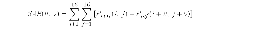
This part of motion estimation is called block matching. Block matching is done using a matching criterion. Typical matching criteria are the Sum of Pixel Absolute Errors (SAE) and the Sum of the Squared Pixel Errors (SSE). It is noted that the words Error and Differences are used with equivalent meaning within the same context by those skilled in the art. Hence, SAD and SAE refer to the same block matching computation. Likewise, SSD and SSE are equivalent.
For our example, SSE is defined for each (u, v) offset in the search space as: SSE ( u , v ) = i + 1 16 f = 1 16 [ P curr ( i , j ) - P ref ( i + u , j + v ) ] 2
Figure US06195389-20010227-M00001
where Pcurr is the block being predicted using motion estimation in the current picture and Pref is a candidate block in the search space in the reference picture displaced from Pcurr by the vector (u, v). Although not a requirement for the invention disclosed herein, if the 64×48 search space in our example is assumed to be concentric with the current block, candidate blocks would range in offsets from −24 to +24 in the horizontal and −16 to +16 in the vertical.
For our example, SAE is defined for each (u, v) offset in the search space as: SAE ( u , v ) = i + 1 16 f = 1 16 [ P curr ( i , j ) - P ref ( i + u , j + v ) ]
Figure US06195389-20010227-M00002
The candidate block that globally minimizes the matching criterion is selected as the best matched block and its corresponding displacement from the coordinates of the current block becomes the motion vector for the current block. The motion vector is encoded in a way that it is fully recoverable from the compressed video stream produced by the encoder engine so that a compliant decoder engine can perform motion compensation during the reconstruction of the current picture. Hence, the output of motion estimation is a motion vector for the current block that indicates the displacement of the coordinates of the top left comer of the current block from the coordinates of the corresponding comer of the predictor.
Each picture in a digitized video sequence consists of three planes of information, one of luminance and two of chrominance. Motion estimation is typically performed in the luminance domain whereas motion compensation must be performed for all three planes to reconstruct the pictures. Each plane of information consists of 8-bit values (i.e., bytes). Typically, the dimensions of the luminance plane are equivalent to the picture resolution and each pixel has its own 8-bit luminance representation.
For our example, SSE would require 256 subtractions, 256 squaring operations (i.e., multiplies), and 255 additions for each candidate. SAE replaces the multiply operation with an absolute value. Matching criteria of lesser computational complexity are rarely employed in practice due to their inferior prediction performance. Hence, motion estimation is a computationally intensive operation with either the SAE or SSE matching criterion. Furthermore, for each block in the current picture, the matching criterion must be computed for each considered candidate block in the reference picture. Pictures of size equal to CCIR 601 resolution (720×480) have 1350 non-overlapping 16×16 blocks that individually undergo motion estimation. For a search space of size of 64×48 (i.e., 1617 candidate blocks), an encoder engine with a motion estimation system that considers every candidate block must compute the block matching criterion approximately 2,182,950 (1350×1617) times per picture, with pictures being encoded at the rate of 30 pictures per second. Consequently, motion estimation is typically the most compute-intensive component of hybrid video coding methods.
The full search motion estimation method described above guarantees locating a predictor block in the search space that produces the global minimum score for the matching criterion but requires an enormous amount of compute power. The method works well where costly encoder engines can be tolerated. Difficulties arise, however, when the encoder engine is part of a consumer system such as a video telephone. Cost constraints here require that the encoder engine be implemented using a relatively low-cost processor such as a low-cost digital signal processor (DSP) or RISC processor, and the demands of the full search motion estimation method will exceed the capabilities of the low-cost processor. In such situations, so-called fast motion estimation methods must be utilized.
Fast motion estimation methods
The aim of fast motion estimation methods is to reduce the number of candidate blocks that are compared with the current block. The drawback of these methods is that there is no guarantee that the candidate that in fact best matches the current block will be chosen as the predictor. The end effect of the methods is that a reduction in computation cycles is traded for either lower picture quality or less compression, or both. The proposed methods can be categorized as follows.
1. Methods that reduce the number of candidate blocks in the search space that are considered as predictors by using heuristics. Examples of such methods are the logarithmic search and the three-step search methods.
2. Hierarchical search methods that simultaneously reduce the number of pixels in the computation of the block matching criterion and the number of considered candidate blocks. These methods generate successive lower resolution of the current and reference pictures by decimating or low-pass filtering by a factor of two in both the horizontal and vertical. Block matching is performed at the smallest available resolution and the results are mapped to the next higher resolution where a limited number of block candidates are considered at displacements localized around the mapped best match.
3. Methods that use motion vectors of blocks that are proximate to the current block to locate candidate blocks.
For further details on the first two classes of methods, see V. Bhaskaran and K. Konstantinides, “Image and Video Compression Standards,” Kluwer Academic Press, 1995, and K. R. Rao and J. J. Hwang, “Techniques & Standards for Image, Video, and Audio Coding,” Prentice Hall Press, 1996. For an example of the third class, see Junavit Chalidabhongse, Sungook Kim, and C.-C. Jay Kuo, “Fast Motion Vector Estimation for Video Coding Based on Multiresolution-Spatio-Temporal Correlations,” Proceedings, Visual Communications and Image Processing '96, International Society for Optical Engineering, vol. 2727, pp. 645-656.
The three-step motion estimation method, for instance, reduces the number of candidate blocks by sub-sampling the search space. For a motion vector range of ±7, the three-step method proceeds in a set of three stages, each successively fine tuning the location of the search space per the best matching criterion score found in the set of candidate predictors in the prior stage, and by successively reducing the size of the window of remaining candidate blocks under consideration. The first stage begins by first examining nine candidates with offsets ranging from ±4 from the spatially corresponding origin of the current block in the reference picture, including the candidate at the origin. That is, the coordinates of the nine predictors considered are: (0,0), (4,0), (−4,0), (0,4), (0,−4), (4,4), (4,−4), (−4,4). The offset with the minimum matching criterion value is then used as the origin for examining eight more candidates at offsets of ±2 around this new origin. Finally, the best match found in the second stage is used as the new origin for eight more candidates at offsets of ±1. The displacement found at the end of stage three serves as the predictor for the current block. In all, this method typically requires computing the matching criterion on candidates at 25 different offsets (nine offsets for stage one, eight for stage two, and eight for stage three). It is noted that this method is dependent on the search space size. When the search space is expanded to support a motion vector range of ±15, the number of considered offsets increases to 65 because the first stage consists of the 49 offsets resulting from sub-sampling the search space by 4 in the horizontal and vertical.
Other fast motion estimation methods operate on the same principle as the three-step method. The logarithmic search performs a coarse to fine sub-sampling of the search space with the same offsets as the three-step search for a ±7 motion vector range. However, for a ±15 motion vector range, it requires four stages where the sub-sampling of the search space is performed at offsets of ±8, ±4, ±2, ±1. Although there are less than 33 candidate positions examined using this method for a ±15 motion vector range, its performance is poor since there is a greater chance that method will find a predictor that reflects a local minimum of the search space.
The insight which forms the starting point for techniques involving blocks that are proximate to the current block is that there is a very high probability that areas which are closely related to the current block will move in the same fashion as the current block. Consequently, if a motion vector for a block in a closely-related area is known, there is a high probability that the current block will have that motion vector. It therefore makes sense to use the motion vector from one of these related blocks to locate a candidate block in the reference picture for the current block. The candidate block is simply that block in the reference picture whose location in the reference picture is such that when the motion vector from the related block is applied to it, the result is the current block. A further insight is that in a digital picture, a block that is related to another block is liable to be located in close proximity to the other block. The proximity may be either with regard to blocks in previously-encoded pictures or with regard to blocks in the current picture. One will thus often be able to substantially reduce the number of blocks that must be compared to find the predictor for the current block by simply beginning the search for the predictor with candidate blocks that are located using blocks that are in close proximity to the current block. Such blocks will be termed in the following proximate blocks.
The techniques of the Chalidabhongse, et al. reference use proximate blocks in the current picture and in the picture that precedes the current picture to find a best candidate, and that candidate is used as a starting point for further refinement which works by searching the eight points around the best candidate, using the best candidate found in that search in a further eight points, and so on until a matching result that is below a threshold is reached. Other variations on this technique are presented, and the reference also discloses how the technique may be used in a hierarchical search.
Problems with known motion estimation techniques
The fast motion estimation techniques described above all offer an unattractive trade off between the number of candidate blocks and the probability that the best predictor will be found. Additionally, none of the fast motion techniques takes into account the fact that digital systems built for consumer use have strict memory constraints, and consequently strict constraints on the size of the search space. In particular, digital system built for consumer use employ digital signal processors (DSPs) that operate most efficiently on data contained in a RAM internal to the DSP, and consequently, searches are done most efficiently if the entire search space can be transferred to the DSP's internal RAM. Since the size of the search space is constrained in this fashion, the search techniques must ensure that there is a very great possibility that the search space contains the predictor. The methods described above consider only a subset of the blocks in their search spaces as candidates, and consequently cannot efficiently use their search space or the memory in which the search space is contained. Moreover, the only way that the methods described above can efficiently increase the range over which they examine candidates is by increasing the amount of internal RAM in the DSP. Hence, these methods necessarily give inferior motion estimation when employed in systems built for consumer use.
It is noted that it is not practical to transfer one candidate block at a time from memory that is external to the DSP into internal DSP Data RAM because adjacent candidate blocks can have as much as 15 of 16 columns (or rows) in common and because it would impose severe delay on a real-time system. Hence, it is more efficient to transfer as much area from the search space as possible into internal DSP Data RAM in a given operation. The above problems are particularly acute with hierarchical search methods. These methods require additional memory for the multi-resolution versions of the current and reference pictures. They also require multiple accesses to external memory to store and retrieve the different resolutions of the reference picture.
It is an object of the techniques disclosed herein to overcome the foregoing problems of motion estimation by providing ways of locating a predictor block for a current block which are particularly well-adapted to use in encoding systems that require efficient use of memory.
SUMMARY OF THE INVENTION
The object is attained by taking motion vectors from blocks that are proximate to the current block, applying the motion vectors to the current block to locate candidate blocks in a reference picture, and then using the candidate blocks to define a portion of the search space. The search space that is so defined is generally small enough to be loaded in its entirety into the internal RAM of the processor used to do the block comparison, but is not limited to a simple projection of the internal RAM of the processor onto external memory.
Other aspects of the invention include improved techniques for limiting the search for the predictor, using a non-rectangular search space centered on a current best candidate to further refine the search for the predictor block, dynamically varying the number and locations of the proximate blocks whose motion vectors are used to locate the candidate blocks as dictated by the availability of motion vectors for the proximate blocks, by the availability of processor cycles, and by the values of previously-determined motion vectors.
Still other objects and advantages of the invention will be apparent to those skilled in the arts to which the invention pertains upon perusing the following Detailed Description and Drawing, wherein:
BRIEF DESCRIPTION OF THE DRAWINGS
FIG. 1 is a drawing which provides an overview of digital picture encoding;
FIG. 2 is a drawing which shows proximate blocks and candidate blocks used in a preferred embodiment.
FIG. 3 is a drawing showing proximate blocks in the current picture;
FIG. 4 is a drawing showing additional proximate blocks in the current picture;
FIG. 5 is a drawing showing candidate blocks in the second phase of the HME method;
FIG. 6 is a flowchart of a preferred embodiment of the HME method;
FIG. 7 is a diagram showing a required portion of a search space;
FIG. 8 is a first diagram showing computation of the required portion;
FIG. 9 is a second diagram showing computation of the required portion;
FIG. 10 is a third diagram showing computation of the required portion;
FIG. 11 is a fourth diagram showing computation of the required portion; and
FIG. 12 is a block diagram of the relevant portions of an encoding system in which the preferred embodiment is implemented.
The reference numbers in the drawings have at least three digits. The two rightmost digits are reference numbers within a figure; the digits to the left of those digits are the number of the figure in which the item identified by the reference number first appears. For example, an item with reference number 203 first appears in FIG. 2.
DETAILED DESCRIPTION
The following Detailed Description first describes how candidate blocks are selected in a preferred embodiment and then shows how candidate blocks selected according to the techniques may be used to predict the search space required for the new techniques.
A Preferred Embodiment of the Techniques: FIG. 2
In a preferred embodiment, the techniques just described are employed in a two-phase search for the predictor for the current block. The first phase localizes the area in which the predictor will be searched for and the second phase refines the search within a predefined 2-dimensional search space whose shape is predefined or determined by the results of the first phase. The search terminates in either phase as soon as a suitable predictor has been found. The first phase uses the location of four or more proximate blocks and the current block to locate corresponding candidate blocks in a reference picture. The proximate blocks have two properties:
they are in particularly close proximity to the current block; and
if the proximate block has a motion vector, it has already been computed.
If a candidate block is found which matches the current block closely enough to be considered the predictor for the current block, the search ends in the first phase; if such a candidate block is not found, the search continues using candidate blocks in the reference picture in a sequence that forms a gradually expanding spiral around the best candidate found in the first phase. The search ends either when a match is found that is close enough or when all of the candidate blocks in the search space of the second phase have been compared with the current block. When looked at simultaneously, in a preferred embodiment, the candidate blocks form a diamond shape with the best candidate from the first phase at the center of the diamond. An advantage of the use of proximate blocks to locate the candidate blocks is that the motion vectors for the proximate blocks used in the first phase are known prior to the beginning of the first phase; consequently, they can be used to determine the search space for the first phase and the search space can be preloaded into the DSP's internal DRAM prior to the beginning of the first phase. Moreover, because the best candidate block to be provided by the first phase is both in the search space for the first phase and is used as the center of a diamond shape of predetermined size for the second phase, the search space for the first phase can be expanded to a larger rectangular search space that encompasses a diamond shape centered on any of the blocks in the search space and the expanded search space can be preloaded into the DSP's internal DRAM prior to the first phase.
Phase 1: FIGS. 2 and 6
FIG. 2 shows the proximate blocks 202 that are first considered for the first phase of the search. As will be described in detail below, more proximate blocks may be employed or others may be substituted for the proximate blocks of FIG. 2. Current block 203 and proximate blocks 202 are used to find a predictor for current block 203 of current picture 201 in search space 219 of reference picture 101. In the preferred embodiment, encoding of current picture 201 is done in raster-scan order, that is, the blocks of the current picture are encoded in rows, with the blocks in each row being encoded from left to right and the rows being processed from top to bottom of the picture. Thus, blocks in rows above the row containing the current block have already been encoded, as have blocks to the left of the current block in the current block's row. Since these blocks have already been encoded, any motion vectors they may have are already available. In the preferred embodiment, five candidate blocks are found using a minimum of four proximate blocks and the current block. The four proximate blocks first considered for use in the first phase are one block of last picture to be encoded 220 and three blocks of current picture 201. The one block of last picture to be encoded 220 has the same x and y coordinates in picture 220 that the current block has in current picture 201. A block in a different picture that has the same coordinates as the current block is termed herein a spatially corresponding block. The three proximate blocks in current picture 201 are the three blocks that are adjacent to current block 203 and may already have motion vectors. Adjacent here means having at least a comer that touches an edge or comer of the current block. The blocks used to locate the five candidate blocks are thus the following:
1. Current Block (CB) 203, used to locate Reference Picture Spatially Corresponding Block (RPSCB) 227, the block in reference picture 101 that has the same x and y coordinates as current block 203, or put another way, the block in reference picture 101 for which current block 203 has the motion vector (0,0);
2. Last Picture Spatially Corresponding Block (LPSCB) 221 in last encoded picture 220 that has the same x and y coordinates as current block 203;
3. West Adjacent Block (WAB) 205 in the current picture;
4. North Adjacent Block (NAB) 207; and
5. Northeast Adjacent Block (NEAB) 209.
In the preferred embodiment, current picture 201 and last picture encoded 220 each have an associated look up table that has an entry for each block in the picture. If a motion vector has been calculated for the block, the entry for the block contains the block's motion vector. If no motion vector has been calculated, the entry contains null values. For instance, in FIG. 2, current picture 201 has a look up table 210, and in table 210 are entries for the motion vectors for proximate blocks 202. Entry 213 has the motion vector for proximate block 207. This is the North Adjacent Motion Vector (NAMV). Entry 215 has the motion vector for proximate block 209. This is the Northeast Adjacent Motion Vector (NEAMV). Entry 217 has the motion vector for proximate block 205. This is the West Adjacent Motion Vector (WAMV). Similarly, in look up table 218 for last encoded picture 220, there is a motion vector entry 229 for proximate block 221. This is the LPSCB Motion Vector (LPSCBMV).
The motion vectors for the above five proximate blocks are used to locate five candidate blocks in reference picture 101. One of the candidate blocks is RPSCB block 227 in reference picture 101; the other four are located by applying the motion vector for one of the proximate blocks in current picture 201 or last picture encoded 220 to the x and y coordinates (i,j) of block 227 in reference picture 101. Thus, candidate block 225 is located using motion vector (a,b) 217 from proximate block 205 by applying motion vector (a,b) to coordinates (i,j) to obtain coordinates (i+a,j+b) for candidate block 225. The block in current picture 201 with motion vector (0,0) relative to block 227 is of course current block 203. The five candidate blocks can thus be described as follows:
1. RPSCB block 227 of reference picture 101;
2. the candidate block at the offset found by applying motion vector 217 to the coordinates (i,j) of RPSCB 227;
3. the candidate block at the offset found by applying motion vector 213 to the coordinates (i,j);
4. the candidate block at the offset found by applying motion vector 215 to the coordinates (i,j); and
5. the candidate block at the offset found by applying motion vector 229 to the coordinates (i,j).
The motion vector of current block 203 with regard to RPSCB 227 is of course (0,0), and current block 203 will match RPSCB 227 if there has been in fact very little or no motion of current block 203 with regard to RPSCB 227.
Details for the foregoing may be found in FIG. 6, which is a flow chart 601 for both phases of a preferred embodiment of the hybrid motion estimation technique. The technique involves three threshold values whose derivation will be explained below. In the immediately following discussion, we will be concerned only with Phase 1 603. In the discussion, reference numbers in parentheses indicate blocks in flow chart 601. Beginning with START HME 604, the first step is to test for motion of current block 203 relative to RPSCB 227 by comparing current block 203 with RPSCB 227(605). If the comparison shows a match between current block 203 and RPSCB 227 such that the matching criterion is below a first threshold, there is a very high probability that there has been very little or no motion with regard to current block 203 between the current picture and reference picture 101 (607). In this case, RPSCB 227 is the predictor for current block 203 and there is no need to examine other candidates. Thus, as shown by arrow 608, the method immediately goes to step 619 and then exits at 621.
If the matching criterion is not below the first threshold, the motion vectors for the four remaining proximate blocks 205, 207, 209, and 221 are used to locate candidate blocks 225 in search space 219 (609). Each candidate block 225 is then compared with current block 203 as described above, and the best-matching block, that is, the one with the lowest matching criterion score, is selected as the predictor (611). If this predictor has a matching criterion score which is less than a second threshold (613), it is selected as the predictor for current block 203 and as shown by arrow 615, the method exits via block 619 to 621, as described above. Otherwise, the method continues with Phase 2 623 (arrow 617), which will be described in more detail below.
Locating a Candidate Block from LPSCB 221
Last encoded picture 220 does not necessarily have to be the reference picture. For example, when consecutive bi-directional (B type) pictures are transmitted in the MPEG video coding standard, the last encoded picture may be a B picture and therefore not a reference picture. Also, the last encoded picture does not necessarily have to be a picture that will be displayed prior to the current picture. For example, in the MPEG video coding standard, a predicted picture (P type) is transmitted prior to a B picture but displayed after the B picture. In this case the P picture is a reference. The MPEG video coding standard is explained in detail in ISO/IEC International Standard IS 11172-2, “Information technology—Coding of moving pictures and associated audio for digital storage media at up to about 1.5 Mbits/s—Part 2: Video,” 1993 and ITU-T Recommendation H.262 (1995): “Generic coding of moving pictures and associated audio: video,” (ISO/IEC 13818-2). As explained in detail below, the candidate obtained from proximate block 221 in last picture 220 can be obtained directly from the motion vector of block 221 or computed by proportionally scaling in the temporal domain the X and Y coordinates of that motion vector.
Computation of Candidate Block offset from Motion Vector in last Encoded Picture
The following discussion will first describe the temporal relationships between pictures that are possible in sequences of encoded video images and will then describe how these temporal relationships affect the computation of the motion vector used to determine the candidate block 225 for which LPSCB 221 is the proximate block.
A digital video sequence originates at a camera where a scene is captured as consecutive pictures of fields (interlaced pictures) or frames (progressive pictures). Pictures are captured by the camera at a specified picture rate. For instance, an NTSC camera captures fields at approximately 60 Hertz. If the pictures from a camera are in analog format, they are digitized and spatially scaled to the required spatial resolution by the encoder engine. Once in digital format, a temporal reference is associated with each picture to keep track of the time that it was captured in relation to other pictures and therefore facilitate the maintenance of their display order. Hence, a typical sequence of pictures generated by a camera is represented by: P1, P2, P3, P4, P5, . . . Pk, where the subscript signifies the display order of the pictures.
Since real-time cost-effective encoder engines in multimedia systems such as those for video-phone applications, have limited processing power, the encoder engine may encode pictures at a slower rate than the rate at which the camera outputs pictures. Furthermore, the rate control component of the encoder engine may dynamically abstain from encoding pictures according to its computational load or the fullness of its output buffer. Consequently, the actual set of pictures from a picture sequence that undergo compression and transmission may have gaps corresponding to the pictures that the encoder engine had to discard. For example, a compressed picture sequence could potentially be: P1, P5, P8, P11 P14, . . . Pk because:
1. the encoder engine is designed (or intended) to operate at 10 pictures per second, and
2. the first picture of a sequence overflows the output buffer since it does not benefit from the superior data reduction capabilities offered by motion estimation.
That is, in this example, the encoder engine is designed to compress every third picture but because P1 results in a large number of bits in compressed form, the encoder engine has to disregard P2 through P4. Then by the time that P5 arrives, the encoder engine's output buffer is sufficiently drained to allow compression of P5.
Further, in many encoding schemes, not every encoded picture is a reference picture. In these schemes, such encoded non-reference pictures are inserted between the reference pictures. Such schemes enable temporal picture scalability (i.e., picture dropping) by a compliant decoder engines of less computational power and/or allow random access in compressed digital video streams. Finally, the order in which pictures are encoded may differ from their display order. An example here is MPEG, which attains more efficient compression of high motion video sequences by permitting a picture to refer to a future reference picture. The order in which the encoder engine encodes pictures is the picture transmission order.
The following cases will exemplify the computation of the displacement of the candidate block from the motion vector of the spatially corresponding block in the last encoded picture. This computation is based on:
1. the coordinates of the contributed motion vector, (x, y), and
2. the temporal relationship between:
the reference picture,
the last encoded picture, and
the current picture.
All pictures are assumed to be part of a sequence presented to the encoder engine with display order: Pa, Pb, Pc, Pd, Pe, . . . Pi Pj, Pk, . . . , in which the temporal relationship implies that a<b <c<d<e<. . . I<j<k . . . and so on. For generalizing the following description, we employ the subscripts: k, m, and v, with the display order condition: k<m<v, but without any constraints in the temporal disparity (i.e., how much temporal separation exists) between the pictures.
In all of the following cases, if the computed displacement, (newX, newY), results in a candidate block with any part of its area protruding beyond the boundaries of the permitted search space (i.e., outside the allowed motion vector range), the candidate block is disregarded or substituted by another eligible candidate block as explained below under Boundary Conditions.
In each respective case below, the computation is applicable only to the third compressed picture (i.e., the third picture in the transmission order) since two temporal relationships of previously transmitted pictures are required.
Case 1—display order=transmission order;
last encoded picture is also “past” reference picture
Pictures in display order: Pk, Pm, Pv,
Transmission order of picture - current picture: Pk, Pm, Pv, (same as
display
order)
Last encoded picture prior to current picture: _, Pk, Pm,
Reference Picture for current picture: _, Pk, Pm,
Then for picture Pv: newX = floor ( X ( v - m m - k ) + 0.5 ) newY = floor ( Y ( v - m m - k ) + 0.5 )
Figure US06195389-20010227-M00003
Where 0.5 is added to round-off to the nearest integer prior to truncation as implied by the floor function . This case is typical in H.261 and H.263 video coding. For details, see ITU-T Recommendation H.261 (1993): “Video codec for audiovisual services at p×64 kbits/s” and Draft ITU-TRecommendation H.263 (199?): “Video codec for low bitrate communications.”
Case 2—display order=transmission order;
last encoded picture and current picture use same “past” reference picture
Pictures in display order: Pk, Pm, Pv,
Transmission order of picture - current picture: Pk, Pm, Pv, (same as
display
order)
Last encoded picture prior to current picture: _, Pk, Pm,
Reference Picture for current picture: _, Pk, Pk,
Then for picture Pv: newX = floor ( X ( v - k m - k ) + 0.5 ) newY = floor ( Y ( v - k m - k ) + 0.5 )
Figure US06195389-20010227-M00004
Where permissible by the specification and syntax of a video encoder engine, this case allows a compliant decoder engine to drop either Pm or Pv for downward temporal scalability.
Case 3—display and transmission order differ;
last encoded picture and current picture use same “future” reference picture
Pictures in display order: Pk, Pm, Pv,
Transmission order of picture - current picture: Pv, Pk, Pm,
Last encoded picture prior to current picture: _, Pv, Pk,
Reference Picture for current picture: _, Pv, Pv,
Then for picture Pm: newX = floor ( X ( v - m v - k ) + 0.5 ) newY = floor ( Y ( v - m v - k ) + 0.5 )
Figure US06195389-20010227-M00005
Where permissible by the specification and syntax of a video encoder engine, this case is useful for compressing high motion video that exhibits scene changes.
Case 4—display and transmission order differ;
last encoded picture is also reference picture, except that Pk is a “past” reference picture to Pv and Pv is a “future” reference picture to Pm
Pictures in display order: Pk, Pm, Pv,
Transmission order of picture - current picture: Pk, Pv, Pm,
Last encoded picture prior to current picture: _, Pk, Pv,
Reference Picture for current picture: _, Pk, Pv,
Then for picture Pm: newX = floor ( X ( m - v v - k ) + 0.5 ) newY = floor ( Y ( m - v v - k ) + 0.5 )
Figure US06195389-20010227-M00006
Where permissible by the specification and syntax of a video encoder engine, this case allows a compliant decoder engine to drop either Pm or both Pm and Pv for downward temporal scalability.
Case 5—display and transmission order differ;
last encoded picture is also reference picture, except that Pv is a “future” reference picture to Pk, and Pk is a “past” reference picture to Pm
Pictures in display order: Pk, Pm, Pv,
Transmission order of picture - current picture: Pv, Pk, Pm,
Last encoded picture prior to current picture: _, Pv, Pk,
Reference Picture for current picture: _, Pv, Pk,
Then for picture Pm: newX = floor ( X ( k - m v - k ) + 0.5 ) newY = floor ( Y ( k - m v - k ) + 0.5 )
Figure US06195389-20010227-M00007
Using other Proximate Blocks in Phase 1: FIGS. 3 and 4
As shown in FIG. 3, northwest adjacent block 301 can be used in Phase 1 to locate a candidate block 225 in the same fashion as the other proximate blocks 202. Block 301 can be used either to locate a sixth candidate block or in place of one of proximate blocks 205, 207, or 209. In the latter case, the encoder engine keeps a record of which adjacent block provided the motion vector for the predictor for each block in current picture 201 whose motion vector has been determined and uses this information to determine which three of the four adjacent blocks (northwest, north, northeast, west) should be used to contribute their motion vectors as predictors for the current block. The northwest block also serves as a replacement when one of the other blocks 205, 207, or 209 does not exist in the picture (that is, towards the right-most part of the picture) or when a motion vector does not exist for one (or more) of the other three adjacent blocks because of unsatisfactory motion estimation performance (i.e., the best matching error found was not acceptable).
The set of proximate blocks 202 used during Phase 1 of the hybrid motion estimation (HME) method is further not limited to blocks 227, 221, 205, 207, 209, and 301. As shown in FIG. 4, additional candidates 225 can be obtained by using motion vectors from proximate blocks in the current picture where motion estimation has already been performed. Some of these additional proximate blocks appear as the six blocks in shaded area 401 of FIG. 4. The bound on the number of proximate blocks that can be used in Phase 1 of the HME method is imposed by the computational power of the DSP-based encoding engine and by the need to reserve processor cycles for the block matching computations of Phase 2 of the HME. The closer a proximate block is to the current block, the more likely that it will exhibit similar translational motion. Hence, the preferred additional proximate blocks are those adjacent to the west, northwest, north and northeast blocks. These additional blocks are shown as shaded area 401. The shaded blocks can be used as proximate blocks in Phase 1 of the HME method when the encoder engine has surplus processor cycles or when any of the proximate blocks already being used in Phase 1 cannot supply a candidate block.
Phase 2 of Hybrid Motion Estimation: FIGS. 5 and 6
In the event that the best matching criterion score found in Phase 1 exceeds Threshold2, it is assumed that there may be a better match to the current block elsewhere in the search space. Therefore, the hybrid motion estimation method continues to Phase 2 where a search for a more satisfactory predictor is conducted in a region centered around the predictor located by Phase 1, termed herein Predphase 1.
The HME method proceeds to Phase 2 under the assumption that a better predictor to the current block lies in close proximity to the location of Predphase1. For low bandwidth applications such as video-phone systems, the HME method conducts a search for a better candidate block on a diamond-shaped region or area 505 (rather than a rectangular one). FIG. 5 shows this region 505, comprised of the blocks numbered “1” through “21” and its relationship to Predphase1 501 in search space 201. In FIG. 5, the center of the search area, shown as the block with the number “1,” represents 16×16 Predphase 1 block 501. However, for the purpose of simplifying the depiction of the spiral-ordered search, the remaining blocks are also shown as the same size as the 16×16 center block when in actuality they are one-pixel displacements away from the center. As shown by the dimensions in FIG. 5, all blocks except the center block represent a one-pixel displacement rather than a 16×16 block.
Even when a rectangular region 503 is centered at Predphase1 during Phase 2, the candidate block that produces the best matching criterion score tends to be found within the diamond-shaped area 505 bounded by the rectangular region 503. Consequently, the HME method saves additional computation by omitting candidate blocks with displacements outside the diamond-shaped region. The saved computation is then used to enlarge the diamond-shaped region and that in turn enables consideration of additional candidate blocks that can potentially result in a better matching criterion score. Furthermore, the diamond-shaped region is designed to consider more horizontal candidate displacements than vertical positions, as shown in FIG. 5, because typical consumer video-phone pictures in the home tend to exhibit a horizontal-like motion due to camera panning (i.e., panning to capture members of the family in the living room).
In Phase 2 of the HME Method, the spiral search within the diamond-shaped region is preferably conducted in a specific order as indicated by the increasing number label of the block to further minimize computation. The closer a candidate block is to Predphase1 501, the more likely it is to have a matching criterion score that is better than the score at Predphase1 501. Hence, candidate blocks are considered in a counterclockwise (or alternatively clockwise) spiral outward order (away from Predphase1 501 ).
The method used to locate a predictor better than Predphase1 501 is shown in Phase 2 623 in FIG. 6. At 625, diamond-shaped region 505 is set up; then a loop consisting of blocks 627, 629, 631, and 637 is executed until either a candidate has been found whose matching criterion score for the match with current block 629 is sufficiently low, that is, in the preferred embodiment, less than threshold 3, or until all of the candidates in diamond 505 have been examined. In the former case (block 631 and arrow 633), the candidate block is the predictor and the method terminates via 619 and 621; in the later (block 637 and arrow 641, the Phase 2 candidate block with the minimum score on the matching criterion is the predictor and the method terminates via blocks 643, 645, and 621.
Since diamond 505 is centered on Predphase1 501, it may be implemented by a lookup table of the displacements of blocks 2-21 from Predphase1 501, and the addresses of the candidates examined during Phase 2 may be computed using this lookup table. Although the shaded area of rectangle 503 outside the diamond-shaped region in FIG. 2 is not used during Phase 2, for practical reasons, the effective area that must be in DSP Data RAM for execution of Phase 2 is the complete 22×22 rectangular region 503 (484 bytes). The effective area required beyond the 16×16 block is an extension of three pixels in each direction. This Delta is incorporated in the calculation of the required search space area for Phase 1 that is described below. Alternatively, this data transfer can be dispatched immediately after Predphase1 501 is determined during Phase 1. In differentiation to fast motion estimation methods (discussed above) that use a sequence of steps to home in on the final result, an additional novelty of the HME method employs a non-rectangular-shaped search area that is mapped on the target (Predphase1) and a spiral ordered search within this reduced search area.
Alternative Modes of Operation for Phase 2
The search area for Phase 2 of the HME method is not limited to the specified region size or shape shown in FIG. 2 but can be increased with additional displacements in the case of more powerful processors and/or surplus DSP Data RAM.
Since the number of processor cycles expended with the HME method varies depending on how quickly a satisfactory predictor is found, in an alternative mode of operation of this invention the size of the Phase 2 search space region is dynamically altered based on the surplus processor cycles.
In another alternative mode of operation, the shape of the region is dynamically selected from a set of pre-defined shapes or customized based on:
1. the location of Predphase1 501 relative to the current block along with the relative location of the block contributing the motion vector for Predphase1 501; or
2. the general orientation of the set of candidate blocks in Phase 1 relative to the current block.
Therefore, if the general orientation of the set of candidate blocks has a much larger Y-component than a X-component, a vertically-biased diamond-shaped region is used. Hence, an additional feature of this invention is that the skew and orientation of the diamond-shaped region can be dynamically adjusted. However, preferable to dynamically calculating the shape of the Phase 2 search space region is a mode of operation that selects a shape and its associated lookup table for the Phase 2 search order from a small set of pre-defined shapes. One particularly usefull set of pre-defined shapes consists of four diamond-shaped entries: one horizontally-biased, another vertically-biased, and two diagonally-biased (one oriented at 45 degrees and the other at 135 degrees).
Determining Threshold1, Threshold2, and Threshold3
In general, Threshold1 Threshold2 Threshold3. One reason for this is that in general, the more cycles a processor expends to find the predictor, the better the match between the predictor and the current block should be. Another is that motion vectors are encoded as differences in magnitude between the magnitude of the motion vector for the current block and the magnitude of the motion vector of a previously encoded block in the current picture as specified by the syntax and the semantic rules required for a compressed video stream. Consequently, the greater the difference in the magnitude, the more bits required to represent the magnitude in the compressed representation of the block.
Each threshold is computed by adding a dynamically-determined Δ value to a fixed component. In the preferred embodiment, which employs 16×16 blocks and the SAE matching criterion and has a data rate of 112 Kbs,
Threshold1=512+Δ1
Threshold2=512 +Δ2
 Threshold3=512 +Δ3
where Δ123. The values of Δ are determined as follows:
Δ1: the value is controlled by the encoder's rate control mechanism; for QCIF resolution pictures (that is, 176×144) at 15 frames per second, it can have a maximum value of 1280.
Δ2: 0.25(Δ13)
Δ3: f(picture resolution, picture rate, data rate, and DSP cycles), where the value of Δ3 may range over the interval [0,512].
At the 112 Kbs data rate, Threshold1 may vary over the interval [512,1024].
Boundary Conditions
For some blocks undergoing compression, one or more proximate blocks may not have a usable motion vector. Such cases arise when either the proximate block is outside the boundaries of the current picture or when a motion vector does not exist because of unsatisfactory motion estimation performance (i.e., the best matching error found was not acceptable and the designated block was compressed without motion estimation). A similar situation arises when any part of a candidate block identified by a proximate block falls outside the boundaries of the permitted search space. In all three of these situations, replacement proximate blocks are employed as discussed above and explained in FIGS. 3 and 4.
The following consist of other conditions where candidate blocks are undefined:
The current block is in the first “row of blocks” (i.e., the first slice in MPEG or the first GOB in H.263) of the current picture and the current picture is the first picture where motion estimation is to be done.
The current block is in the first “row of blocks” in a section of the picture dispatched to a processor in a parallel processing environment. That is, the picture is partitioned into sections, each a contiguous set of “rows of blocks,” and the encoder engine has multiple processors (e.g., a Texas Instrument DSP TMS320C80) that execute the HME method independently in parallel on each section.
In such cases, the respective undefined motion vector is set to (0,0) or the hybrid motion estimation method performs motion estimation on these blocks using a traditional fast motion estimation method.
Dynamic Calculation of a Required Portion of Search Space 219 for the HME method: FIGS. 7-12
Obviously, the only part of reference picture 101 which need be in the internal RAM of the DSP for Phase 1 of the method 601 is that portion which contains the candidate blocks being used in Phase 1. The locations of the candidate blocks can be computed from the motion vectors of the proximate blocks, and these are known prior to Phase 1. Consequently, the portion of search space 219 that contains the candidate blocks, termed herein the required portion, can be determined prior to Phase 1 and can also be loaded into the internal RAM of the DSP prior to Phase 1. Moreover, the part of the search space required for Phase 2 can also be computed from the locations of the candidate blocks, and consequently, the required portion for both phases may be loaded into the internal RAM
FIG. 12 is a block diagram of a video picture encoding system 1201 that shows the relationship between DSP 1223 and the remainder of system 1201. System 1201 receives analog images from a video camera 1203; these are converted to a digital representation in A/D converter 1205 and input to External RAM 1207 by routing digitized picture data via FIFO memory 1217 and controlled by Control Logic 1218, which also coordinates operation of external RAM 1207 and DSP 1223. External RAM 1207 contains two ping-pong picture buffers, 1208 and 1210, one of which always contains current picture 201 currently being encoded and the other of which is receiving the next picture to be encoded 1209 from camera 1203. External RAM 1207 further contains, in buffer 1212, reconstructed representations of the digital reference pictures needed to encode current picture 201. As the current picture is compressed, its decoded representation is reconstructed in 1212. The current picture is destined to be used as a reference picture for the compression of subsequent pictures. The reconstructions in 1212 are made by decoding the encoded digital pictures as they are being encoded. Shown is the reconstructed reference picture 101 with search space 219. The output buffer 1211 receives current picture 201 in its compressed representation as it is encoded and outputs the encoded picture to the remainder of the system. Output buffer can contain portions of the last encoded picture in compressed format that remain to be output.
A further portion of external RAM 1207 contains data used by DSP 1223 in encoding current picture 201; included in this data are the thresholds 1213 used in HME method 601 and the look up tables of motion vectors 210 and 218 for current picture 201 and last picture encoded 220. External RAM 1207 finally contains the program code 1215 which DSP 1223 executes when it performs encoding operations.
DSP 1223 has three main components: DSP hardware 1227, which contains the circuits that actually performs the processing operations, instruction RAM 1229, which contains the portion of DSP program code 1215 that DSP 1223 currently needs for the operations it is performing, and data RAM 1231, which contains the data currently being used or produced by DSP 1223 in the operations it is performing. DSP 1223 is connected via Bus Interface (BI) 1225 to address bus 1219 and data bus 1221, which are in turn connected to external RAM 1207. DSP 1223 can thus read data from RAM 1207 and write data to RAM 1207, but reading from and writing to RAM 1207 are far slower than reading from and writing to data RAM 1231. Consequently, the most efficient way to use DSP 1223 is to load all of the data required for a specific sequence of operations performed by DSP 1223 into data RAM 1231 prior to beginning the sequence of operations. More particularly, efficient use of DSP 1223 to perform HME method 601 requires that current block 203, the required portion of search space 1219, look up tables 210 and 218, and thresholds 1213 be loaded into DSP 1223 prior to beginning HME method 601.
FIG. 7 shows required portion 701 and its relationship to search space 219 and five candidate blocks 225(1 . . . 5). Candidate block 225(1) is block 227 of the reference picture that spatially corresponds to current block 203; the motion vectors used to locate the remaining candidate blocks are written in parentheses in the blocks. The first step in establishing portion 701 is to determine the bounds that are necessary if all of the candidate blocks are to be included in portion 701. Typically, because motion vectors of adjacent blocks are highly correlated, the portion 701 which contains all of the candidate blocks is a single area in search space 219 of reference picture 101 that is sufficiently small to fit into DSP Data RAM. In such a case, which is shown in FIG. 7, only one transfer is required to move required portion 701 from external RAM 1207 to internal data RAM 1231. However, in the event that a calculated search space area is large because of large disparity among the candidate blocks, there may not be a portion 701 that is both a single rectangle and small enough to fit into internal DSP data RAM. In this case, a required portion 701 which is small enough to fit may be made up of two or more non-contiguous and possibly overlapping rectangular sections of search space 219. In this case, each rectangular section must be separately transferred from external memory to internal DSP Data RAM. In the following, a method will be explained which locates two minimal-sized rectangles in search space 219 which contain all of the candidates. In almost all cases, the two minimal-sized rectangles are small enough to fit simultaneously into the DSP's internal RAM.
Potential examples of the results of Part 2 of the search space area calculation method are shown in FIGS. 8-11. In FIG. 8, an unused vertical rectangular section of the search space extends from the top to the bottom of the search space. Such section is denoted as Section V. The location of the right side of required rectangular Region A 801 with respect to the left side of required rectangular Region B 803 can vary. The rectangular regions could intersect, be disjoint (i.e., there may be another unused vertical rectangular section between the regions) or have coincident sides as shown. Hence, there could be up to three unused vertical rectangular sections (one to the left of Region A, another in between the regions, and another to the right of Region B). Sections NW, NE, NE, and SE vary in size. Any of Sections NW, NE, NE, and SE may not be present. Candidate block RPSCB 227 will always be encapsulated by one of the two required regions 801 and 803.
Similarly, the calculated search space area may result in one or more unused horizontal rectangular sections. FIG. 9 shows Sections H1 and H2 extending from the left side to the right side of the search space. FIG. 9 also depicts one of the many ways in which required regions 801 and 803 may be related to each other, namely in that they have an intersection 905. Two other ways in which regions 801 and 803 may relate to each other are shown in FIGS. 10 and 11.
Method for Calculating Required Portion 701 of Search Space 219
Required portion 701 is calculated during Phase 1 of the HME method using a technique which first calculates a required portion 701 made up of a single rectangle, and if the single rectangle is too large to fit into the DSP's internal RAM, then calculates a required portion 701 made up of two minimal rectangular required regions 801 and 803.
Part 1—Single Rectangular Area Calculation Method
1. Each Phase 1 candidate block 225 is found and mapped into search space 219. Recall that the coordinates of a candidate block 225 correspond to its top-left corner (i.e., a motion vector points to the pixel in the top-left corner of a block).
2. The extrema of the X-component and the Y-component of the candidates 225 are found.
3. The extent of the rectangular region that bounds the candidates 225 is found using the following set of equations:
new_X_max=min_X−Delta
new_X_max=max_X+X_block_dimension+Delta
new_Y_min=min_Y−Delta
new_Y max=max_Y+Y_block_dimension+Delta
FIG. 7 shows how the terms of the equations relate to required portion 701. Delta is an extra amount that is added to required portion 701 to accommodate area 503 used in Phase 2 of the HME method. Delta is appropriately clipped (reduced in value) when necessary so that required portion 701 does not extend outside the boundary of search space 219 or the periphery of reference picture 101. In the preferred embodiment, Delta=3.
4. If the resulting required portion 701 is sufficiently small to fit in internal DSP Data RAM, a request is dispatched to transfer the rectangular region into DSP Data RAM and the method of computing required portion 701 terminates at this point. Otherwise, it continues as indicated below.
Part 2—Candidate Block Clustering Method for Two Rectangular Areas
Part 2 is similar to a statistical clustering method. However, the traditional way of agglomerating a sample to a cluster is based on its distance to the centroids of the clusters; the samples are points and the clusters are represented by their centroid—the average of the cluster's constituents (i.e., the samples). Since our samples are blocks (2-D areas) that must be clustered to a rectangular region, this averaging effect is undesirable because it does not necessarily produce two rectangular areas that sum to the minimal aggregate area of required portion 701.
5. Find the two candidate blocks 225, B1 and B2, that are farthest apart and designate them as the initial guides to cluster the remaining Phase 1 candidate blocks 225. At this point in time, B1 and B2 serve as two separate rectangular regions 801 and 803 of the search space, R1 and R2, that will be grown to incorporate the remaining Phase 1 candidate blocks 225. Since in the preferred embodiment there are five Phase 1 candidate blocks 225, three candidates must be mapped to one of the two rectangular regions. Each candidate block 225 is characterized by the coordinates of its top-left comer. Each of the rectangular regions 801 and 803 is characterized by its area and its four comers composed from the extrema of the X-component and the Y-component of the candidates that have been agglomerated into that region. That is, the top-left comer of a rectangular region is at (Xmin, Ymin); the bottom-right corner is at (Xmax, Ymax); the bottom-left comer is at (Xmin, Ymax); and the top-right comer is at (Xmax, Ymin).
6. The distance from each remaining (i.e., unmapped) candidate block 225 to B1 and B2 is found. This is because R1 and R2 are initially a point respectively equivalent to B1 and B2.
7. The candidate exhibiting the smallest distance to a rectangular region is agglomerated to that region. However, if multiple candidates exhibit the same minimum distance to a given rectangular region, each is agglomerated to the respective rectangular region.
8. The coordinates of the four corners of the modified rectangular region(s) are computed by comparing the X and Y-component of the absorbed candidate(s) to the previous extrema of the rectangular region. The area of the modified rectangular region(s) is computed.
Either one or both of R1 or R2 may be modified depending on step 7.
9. If any of the candidates remains unmapped to one of the two rectangular regions, continue to step 10. Else, exit.
10. For each remaining candidate Bi:
Compute the resulting area that would result if Bi is added to R1.
Compute the resulting area that would result if Bi is added to R2.
11. The candidate block whose agglomeration would adds the smallest incremental area to a rectangular region is agglomerated to that region. However, if multiple candidate blocks exhibit the same minimum incremental area, each is agglomerated to the respective rectangular region.
12. The four comers of the modified rectangular region(s) are computed by comparing the X and Y-component of the absorbed candidate(s) to the previous extrema of the rectangular region. The new area of the modified rectangular region(s) is saved. Either one or both of R1 or R2 may be modified depending on step 11.
13. If any of the candidates remains unmapped to one of the two rectangular regions, go to step 10.
14. By applying the equations in step 3, the rectangular regions of search space area demarcated by R1 and R2 are respectively extended in each direction.
Part 2 guarantees the calculation of two rectangular regions of required search space area that result in the smallest aggregate area (i.e., the least amount of data required to be transferred into DSP Data RAM). In an alternative mode of this invention that does not provide this guarantee, the distance between a candidate to the closest comer of a rectangular area is used as the clustering criterion rather than the incremental area of rectangular region. In a third alternative mode of this invention that is simpler but has a smaller probability of producing the smallest aggregate area, steps 7 to 13 are replaced with the single step: Each remaining candidate is mapped to the closest of B1 and B2. When multiple rectangular regions of the search space need to be transferred in sequence, the region containing the (0,0) offset is always transferred first.
Although very uncommon, some implementations of the HME method (i.e., extremely large search spaces) may require more than two transfers from external memory to internal DSP Data RAM. In such cases, the transfers need to be dispatched in sequence to bring multiple rectangular sections of the search space. In the worst case, when the aggregate of the rectangular regions do not fit in internal DSP Data RAM, the search space required for the remaining candidates can be transferred into internal Data RAM while the matching criterion is being computed on candidates in a subset of the search space. It should be noted here that the method of computing required portion 701 just described puts no limitations whatever on the magnitudes of the motion vectors of the proximate blocks used to locate the candidate blocks.
As will be apparent from the foregoing, the techniques described above for calculating the area of required portion 701 of search space 219 are not limited to use with the internal DRAM of DSPs, but can be used in any situation where it is advantageous to move portions of the search space into memory that is more accessible to the processor which is doing the comparisons.
Conclusion
The foregoing Detailed Description has disclosed to those skilled in the arts to which the techniques for motion detection disclosed in the Detailed Description pertain the best mode presently known to the inventors of implementing their techniques. As will be immediately apparent to those skilled in the arts to which the techniques pertain, many other implementations of the techniques are possible. The exact implementation will of course depend on the encoding scheme employed and on the hardware used to do the encoding. The manner in which the threshold values for the method are determined in a given implementation will depend on the encoding scheme, the hardware, and the kind of application the encoding is being done for.
Other variations include the following: the temporal prediction of a block does not necessarily have to come from a block of the same size in the reference picture(s). Hence, portions of a block (e.g., quadrants) can be temporarily predicted from sub-blocks of equivalent dimensions in the reference picture(s). Moreover, the predictor for the current block does not necessarily have to come from a single reference picture but can be generated by choosing the best predictor from predictors obtained from several reference pictures. Alternatively, the predictor can be generated by combining the predictors from the reference pictures, for example, by using a weighted average. Further, the encoder engine can employ reference pictures that are either original pictures or pictures that have been reconstructed from their encodings. However, the encoder engine must employ the reconstructed version of the reference pictures to generate the equivalent digital error signals that compliant decoder engines generate during decompression and reconstruction of pictures. Additionally, the regions that are compared to find the predictor need not be rectangular in shape and the information employed to dynamically select proximate blocks and to shape the area used in the second phase of the search may vary from implementation to implementation.
Since the Detailed Description describes only one implementation of the motion estimation techniques and many other implementations that incorporate the principles of the motion estimation techniques are possible, it is apparent that the Detailed Description must be regarded as being in every respect illustrative and not restrictive and that the scope of the invention disclosed herein is not to be determined from the Detailed Description, but rather from the claims as interpreted with the full breadth permitted by the patent laws.

Claims (34)

What is claimed is:
1. A method for determining whether a candidate region is to be considered as a predictor region, wherein the predictor region is used in estimating motion of a current region in a current picture of a sequence of digitally-represented pictures relative to a predictor region in a reference picture of the sequence, the method including the steps of:
determining motion vectors for a plurality of proximate regions that are proximate to the current region, the plurality of proximate regions including regions that are in the current picture and in a last encoded picture;
locating the candidate regions by applying the motion vectors from the proximate regions to the region in the reference picture that has the same spatial position in the reference picture that the current region has in the current picture;
comparing pixel information for the candidate region with pixel information in the current region; and
determining whether a match between the pixel information in the candidate region and the pixel information in the current region satisfies a first threshold and if so the candidate region is to be considered as the predictor region, otherwise comparing pixel information for regions in an area centered on the candidate region with pixel information in the current region to determine the predictor region, wherein the area centered on the candidate region is non-rectangular and dynamically sized according to a number of processor cycles available in a processor cycle budget to perform the computation.
2. The method set forth in claim 1 wherein:
the proximate region in the last encoded picture is in the same spatial position in the last encoded picture that the current region is in the current picture.
3. The method set forth in claim 1 wherein:
the motion vector for the proximate region in the last encoded picture is determined from a motion vector for the proximate region in the last encoded picture and the temporal relationship between the reference picture, the current picture, and the last encoded picture.
4. The method set forth in claim 1, wherein the method of claim 1 is performed to determine at least some of a plurality of candidate regions and further comprising the step of:
determining an area in a search space from the plurality of candidate regions which contains all of the candidate regions.
5. The method set forth in claim 4 further comprising the step of:
copying the area into memory which is internal to a processor that performs the comparisons prior to performing the comparisons.
6. The method set forth in claim 4 wherein:
the step of determining the area determines a plurality of areas.
7. The method set forth in claim 6 wherein:
the step of determining the plurality of areas determines the areas such that the aggregate size of the areas tends toward a minimum.
8. The method set forth in claim 1, wherein in the step of determining whether a match satisfies a first threshold and otherwise comparing regions in the area centered on the candidate region, the regions are compared with the current region in an order of increasing distance from the candidate region.
9. The method set forth in claim 8, wherein the regions are compared until a match is found with the current region that satisfies a second pre-determined threshold.
10. The method set forth in claim 9, wherein the match required to satisfy the second threshold is closer than the match required to satisfy the first threshold.
11. The method set forth in claim 1, further comprising the step of:
dynamically shaping the area in accordance with a location of the at least one other candidate region relative to the current region.
12. The method set forth in claim 9, further comprising the steps of:
selecting the region in the reference picture that has the same spatial position in the reference picture that the current region has in the current picture as a first candidate region of a plurality of regions in the reference picture; and
determining whether a match between the pixel information in the first candidate region and the current region satisfies a third threshold and if so the first candidate region is to be considered as the predictor region, otherwise comparing pixel information for other regions of the plurality of regions to determine the predictor region.
13. The method set forth in claim 12 wherein:
the third threshold is greater than the first threshold, which is greater than the second threshold.
14. The method set forth in claim 1 wherein:
the region is a block.
15. A method of refining an estimation of motion of a current region in a current picture of a sequence of digitally-represented pictures relative to a predictor region in a reference picture of the sequence, the method comprising the steps of:
defining a non-rectangular area in the search space of the reference picture that includes a candidate region in the reference picture that is the current best candidate to be the predictor region;
comparing regions in the non-rectangular area with the current region until the predictor region is found; and
dynamically sizing the non-rectangular area according to a number of processor cycles available in a processor cycle budget to perform the comparison.
16. The method set forth in claim 15 wherein:
the regions in the non-rectangular area are defined by means of a look-up table.
17. The method set forth in claim 15 wherein:
the non-rectangular area has a diamond shape.
18. The method set forth in claim 15 wherein:
in the step of comparing regions in the non-rectangular area, the regions are compared with the current region in an order of increasing distance from the current best candidate.
19. The method set forth in claim 18 wherein:
in the step of comparing regions in the non-rectangular area, the order of increasing distance is a spiral outward from the current best candidate.
20. The method set forth in claim 15 further comprising the step of:
dynamically shaping the non-rectangular area in accordance with a location of the at least one other candidate region relative to the current region.
21. A method of defining an area in the search space in a reference picture of a sequence of digitally-represented pictures within which a search will be made for a predictor region for a current region of a current picture of the sequence, the method comprising the steps of:
for each region in a set of regions in the current picture that are proximate to the current region and for which a motion vector has already been computed, using the motion vector for the region to locate a candidate region in the reference picture;
dynamically sizing the area according to a number of processor cycles available in a processor cycle budget to perform the comparison; and
using the candidate regions to define the area.
22. The method set forth in claim 21 wherein:
the motion vector may have any magnitude.
23. The method set forth in claim 21 further comprising the step of:
determining the area from the plurality of candidate regions such that the area contains all of the candidate regions.
24. The method set forth in claim 23 wherein:
in the step of using a motion vector for the region to locate a candidate region, the candidate region is located by applying the motion vector for the proximate region to a region in the reference picture which has the same spatial location in the reference picture that the current region has in the current picture.
25. The method set forth in claim 21 further comprising the step of:
copying the area into memory which is internal to a processor which performs the comparisons prior to performing the comparisons.
26. The method set forth in claim 25 wherein:
the step of determining the area determines a plurality of areas.
27. The method set forth in claim 26 wherein:
the step of determining the plurality of areas determines the areas such that the aggregate size of the areas tends toward a minimum.
28. The method set forth in claim 26 wherein:
one of the areas includes a region in the reference picture that has the same spatial position in the reference picture that the current region has in the current picture; and
the areas are loaded separately into the memory which is internal to the processor, beginning with the one area that includes the region in the reference picture that has the same spatial position in the reference picture that the current region has in the current picture.
29. An improved method of using motion vectors of regions proximate to a current region in a current picture of a sequence of digital pictures to locate a predictor region for the current region in a reference picture of the sequence, the method including the steps performed for a given proximate region of locating a candidate region in the reference picture by applying the given proximate region's motion vector to a region in the reference picture which has the same spatial position in the reference picture that the current region has in the current picture and comparing the candidate region with the current region and the improvement comprising the steps of:
determining a number of CPU cycles currently available in a CPU cycle budget to perform the steps of the method; and
determining a number of proximate regions for which the steps of the method are performed based on the number of CPU cycles currently available.
30. The method set forth in claim 29 wherein:
the proximate regions whose number is based on the number of CPU cycles currently available all have previously-computed motion vectors.
31. The method set forth in claim 30 wherein:
the step of determining a number of proximate regions adds additional proximate regions in order of increasing distance from the current region.
32. The method set forth in claim 30 wherein:
the step of determining a number of proximate regions selects additional proximate regions according to the motion vectors for blocks in the current picture whose motion vectors have already been determined.
33. A method of sizing an area in search space of a reference picture of a sequence of digitally-represented pictures for searching for a predictor region for a current region of a current picture of the sequence, the method comprising the steps of:
determining a number of CPU cycles currently available to search for the predictor region; and
sizing the area according to the number of CPU cycles currently available.
34. The method set forth in claim 33 further comprising the steps of:
locating at least one other candidate region in the reference picture for the predictor region; and
dynamically shaping the area in accordance with a location of the at least one other candidate region relative to the current region.
US09/061,625 1998-04-16 1998-04-16 Motion estimation system and methods Expired - Lifetime US6195389B1 (en)

Priority Applications (8)

Application Number Priority Date Filing Date Title
US09/061,625 US6195389B1 (en) 1998-04-16 1998-04-16 Motion estimation system and methods
DE69920429T DE69920429T2 (en) 1998-04-16 1999-04-16 MOTION ESTIMATION SYSTEM AND METHOD
EP99918599A EP1072017B1 (en) 1998-04-16 1999-04-16 Motion estimation system and method
BR9909574-2A BR9909574A (en) 1998-04-16 1999-04-16 Method and system for estimating movement
DE1072017T DE1072017T1 (en) 1998-04-16 1999-04-16 MOTION ESTIMATION SYSTEM AND METHOD
PCT/US1999/008341 WO1999053438A2 (en) 1998-04-16 1999-04-16 Motion estimation system and method
JP2000543926A JP4358990B2 (en) 1998-04-16 1999-04-16 Motion estimation system and method
JP2006067681A JP4410206B2 (en) 1998-04-16 2006-03-13 Motion estimation system and method

Applications Claiming Priority (1)

Application Number Priority Date Filing Date Title
US09/061,625 US6195389B1 (en) 1998-04-16 1998-04-16 Motion estimation system and methods

Publications (1)

Publication Number Publication Date
US6195389B1 true US6195389B1 (en) 2001-02-27

Family

ID=22037021

Family Applications (1)

Application Number Title Priority Date Filing Date
US09/061,625 Expired - Lifetime US6195389B1 (en) 1998-04-16 1998-04-16 Motion estimation system and methods

Country Status (6)

Country Link
US (1) US6195389B1 (en)
EP (1) EP1072017B1 (en)
JP (2) JP4358990B2 (en)
BR (1) BR9909574A (en)
DE (2) DE69920429T2 (en)
WO (1) WO1999053438A2 (en)

Cited By (66)

* Cited by examiner, † Cited by third party
Publication number Priority date Publication date Assignee Title
US20020025001A1 (en) * 2000-05-11 2002-02-28 Ismaeil Ismaeil R. Method and apparatus for video coding
US6411652B1 (en) * 1998-10-23 2002-06-25 International Business Machines Corp. Motion estimation
US6414995B2 (en) * 1999-07-29 2002-07-02 Mitsubishi Denki Kabushiki Kaisha Motion vector detection system
US6418166B1 (en) * 1998-11-30 2002-07-09 Microsoft Corporation Motion estimation and block matching pattern
US20020136302A1 (en) * 2001-03-21 2002-09-26 Naiqian Lu Cascade window searching method and apparatus
US20020150161A1 (en) * 1998-08-18 2002-10-17 Gero Baese Method and configuration for coding a digitized picture, and method and configuration for decoding a digitized picture
US6473460B1 (en) * 2000-03-31 2002-10-29 Matsushita Electric Industrial Co., Ltd. Method and apparatus for calculating motion vectors
US20020158989A1 (en) * 2001-04-25 2002-10-31 Nec Corporation Image encoding device, image encoding method to be used therein and storage medium storing program
US20030053543A1 (en) * 2001-07-24 2003-03-20 Sasken Communication Technologies Limited Motion estimation technique for digital video encoding applications
US20030072374A1 (en) * 2001-09-10 2003-04-17 Sohm Oliver P. Method for motion vector estimation
US20030163281A1 (en) * 2002-02-23 2003-08-28 Samsung Electronics Co., Ltd. Adaptive motion estimation apparatus and method
US20030169264A1 (en) * 2002-01-04 2003-09-11 Emerson Theodore F. Operating system independent method and apparatus for graphical remote access having improved latency
US20030198295A1 (en) * 2002-04-12 2003-10-23 Liang-Gee Chen Global elimination algorithm for motion estimation and the hardware architecture thereof
US20030202591A1 (en) * 2002-03-26 2003-10-30 General Instrument Corporation Methods and apparatus for efficient global motion compensation encoding and associated decoding
US20030206246A1 (en) * 2000-05-18 2003-11-06 Gerard De Haan Motion estimator for reduced halos in MC up-conversion
US20030227971A1 (en) * 2002-06-07 2003-12-11 Siemens Aktiengesellschaft Method and apparatus for video coding
US20030231712A1 (en) * 2002-06-18 2003-12-18 Naren Malayath Motion estimation techniques for video encoding
US20040001544A1 (en) * 2002-06-28 2004-01-01 Microsoft Corporation Motion estimation/compensation for screen capture video
US20040001545A1 (en) * 2002-06-28 2004-01-01 Chienchung Chang Computationally constrained video encoding
US20040057520A1 (en) * 2002-03-08 2004-03-25 Shijun Sun System and method for predictive motion estimation using a global motion predictor
US20040146112A1 (en) * 2003-01-14 2004-07-29 Samsung Electronics Co., Inc. Data storage unit for image compression device
US6813315B1 (en) 2001-04-24 2004-11-02 Vweb Corporation Motion estimation using multiple search windows
US20040247029A1 (en) * 2003-06-09 2004-12-09 Lefan Zhong MPEG motion estimation based on dual start points
US20040247034A1 (en) * 2003-04-10 2004-12-09 Lefan Zhong MPEG artifacts post-processed filtering architecture
US20050013364A1 (en) * 2003-07-14 2005-01-20 Chun-Ming Hsu Method of motion vector determination in digital video compression
US20050053138A1 (en) * 2003-09-09 2005-03-10 Lg Electronics Inc. Method for setting motion vector of digital video
US20050053139A1 (en) * 2003-09-04 2005-03-10 Samsung Electronics Co., Ltd. Method and apparatus for determining reference data unit for predictive video data coding
DE10356090B3 (en) * 2003-12-01 2005-04-21 Siemens Ag Computerized selection and transmission system for parts of pictures has digitization system and has first picture region in reference image compared with several regions in search image
US6891890B1 (en) * 2001-04-24 2005-05-10 Vweb Corporation Multi-phase motion estimation system and method
US20050114093A1 (en) * 2003-11-12 2005-05-26 Samsung Electronics Co., Ltd. Method and apparatus for motion estimation using variable block size of hierarchy structure
US20050129125A1 (en) * 2003-11-17 2005-06-16 Samsung Electronics Co., Ltd. Method and apparatus for pitcure compression using variable block of arbitrary size
US20050152452A1 (en) * 2002-07-15 2005-07-14 Yoshinori Suzuki Moving picture encoding method and decoding method
US6934332B1 (en) 2001-04-24 2005-08-23 Vweb Corporation Motion estimation using predetermined pixel patterns and subpatterns
US20050281341A1 (en) * 2004-06-18 2005-12-22 Stephen Gordon Reducing motion compensation memory bandwidth through memory utilization
US20060039466A1 (en) * 2004-08-23 2006-02-23 Emerson Theodore F Method and apparatus for managing changes in a virtual screen buffer
US20060082591A1 (en) * 2002-01-04 2006-04-20 Emerson Theodore F Method and apparatus for implementing color graphics on a remote computer
US20060233258A1 (en) * 2005-04-15 2006-10-19 Microsoft Corporation Scalable motion estimation
US20070064808A1 (en) * 2005-09-22 2007-03-22 Sanyo Electric Co., Ltd. Coding device and coding method enable high-speed moving image coding
US20070086525A1 (en) * 2004-10-18 2007-04-19 Wataru Asano Motion vector detection method and device of the same
US20070230573A1 (en) * 2006-04-03 2007-10-04 Matsushita Electric Industrial Co., Ltd. Motion estimation device, motion estimation method, motion estimation integrated circuit, and picture coding device
US20070237232A1 (en) * 2006-04-07 2007-10-11 Microsoft Corporation Dynamic selection of motion estimation search ranges and extended motion vector ranges
US20070237226A1 (en) * 2006-04-07 2007-10-11 Microsoft Corporation Switching distortion metrics during motion estimation
US20070271408A1 (en) * 2006-05-18 2007-11-22 Konica Minolta Business Technologies, Inc. Memory administrating method
US20070268964A1 (en) * 2006-05-22 2007-11-22 Microsoft Corporation Unit co-location-based motion estimation
US20080050036A1 (en) * 2006-08-25 2008-02-28 Portalplayer, Inc. Method and system for performing two-dimensional transform on data value array with reduced power consumption
US20080112488A1 (en) * 2003-07-15 2008-05-15 Pearson Eric C Supporting motion vectors outside picture boundaries in motion estimation process
US7408987B1 (en) * 1998-09-07 2008-08-05 Thomson Licensing Method of motion estimation for transmission cost reduction of motion vectors
US20080291209A1 (en) * 2007-05-25 2008-11-27 Nvidia Corporation Encoding Multi-media Signals
US20080294962A1 (en) * 2007-05-25 2008-11-27 Nvidia Corporation Efficient Encoding/Decoding of a Sequence of Data Frames
US20080310509A1 (en) * 2007-06-13 2008-12-18 Nvidia Corporation Sub-pixel Interpolation and its Application in Motion Compensated Encoding of a Video Signal
US20090022219A1 (en) * 2007-07-18 2009-01-22 Nvidia Corporation Enhanced Compression In Representing Non-Frame-Edge Blocks Of Image Frames
US20090225847A1 (en) * 2008-03-04 2009-09-10 Samsung Electronics Co., Ltd. Method and apparatus for encoding and decoding an image by using consecutive motion estimation
US20090296816A1 (en) * 2008-06-02 2009-12-03 David Drezner Method and System for Using Motion Vector Confidence to Determine a Fine Motion Estimation Patch Priority List for a Scalable Coder
US20100013991A1 (en) * 2007-02-20 2010-01-21 Sony Corporation Image Display Apparatus, Video Signal Processor, and Video Signal Processing Method
US20100074336A1 (en) * 2008-09-25 2010-03-25 Mina Goor Fractional motion estimation engine
US20100142761A1 (en) * 2008-12-10 2010-06-10 Nvidia Corporation Adaptive multiple engine image motion detection system and method
WO2012023763A3 (en) * 2010-08-17 2012-05-10 Oh Soo Mi Inter prediction encoding method
US8654855B2 (en) 2011-08-29 2014-02-18 Ibex Pt Holdings Co., Ltd. Apparatus for decoding motion information in merge mode
US8724702B1 (en) 2006-03-29 2014-05-13 Nvidia Corporation Methods and systems for motion estimation used in video coding
US8731071B1 (en) 2005-12-15 2014-05-20 Nvidia Corporation System for performing finite input response (FIR) filtering in motion estimation
US9330060B1 (en) 2003-04-15 2016-05-03 Nvidia Corporation Method and device for encoding and decoding video image data
US9621921B2 (en) 2012-04-16 2017-04-11 Qualcomm Incorporated Coefficient groups and coefficient coding for coefficient scans
US20180182117A1 (en) * 2016-12-27 2018-06-28 Inuitive Ltd. Method for Generating Three Dimensional Images
US10217200B2 (en) * 2012-04-06 2019-02-26 Microsoft Technology Licensing, Llc Joint video stabilization and rolling shutter correction on a generic platform
CN110719482A (en) * 2018-07-13 2020-01-21 腾讯美国有限责任公司 Video coding and decoding method, device, equipment and storage medium
US11528503B2 (en) 2017-12-31 2022-12-13 Huawei Technologies Co., Ltd. Picture prediction method and apparatus, and codec

Families Citing this family (6)

* Cited by examiner, † Cited by third party
Publication number Priority date Publication date Assignee Title
JP4515886B2 (en) * 2003-10-28 2010-08-04 パナソニック株式会社 In-plane predictive coding method
KR100903498B1 (en) 2004-09-29 2009-06-18 텐센트 테크놀로지(센젠) 컴퍼니 리미티드 Motion estimation method
CN101536530B (en) * 2006-11-07 2011-06-08 三星电子株式会社 Method of and apparatus for video encoding and decoding based on motion estimation
EP2104356A1 (en) * 2008-03-18 2009-09-23 Deutsche Thomson OHG Method and device for generating an image data stream, method and device for reconstructing a current image from an image data stream, image data stream and storage medium carrying an image data stream
US9774881B2 (en) * 2014-01-08 2017-09-26 Microsoft Technology Licensing, Llc Representing motion vectors in an encoded bitstream
US9749642B2 (en) 2014-01-08 2017-08-29 Microsoft Technology Licensing, Llc Selection of motion vector precision

Citations (18)

* Cited by examiner, † Cited by third party
Publication number Priority date Publication date Assignee Title
GB2188509A (en) 1986-03-19 1987-09-30 British Broadcasting Corp Video signal processing for bandwidth reduction
EP0446001A2 (en) 1990-03-06 1991-09-11 Victor Company Of Japan, Ltd. Motion vector detection circuit used in hierarchical processing of moving picture signal
EP0565253A2 (en) 1992-04-08 1993-10-13 NCR International, Inc. Apparatus and method for processing payment for a merchandise item
EP0579319A2 (en) 1992-07-16 1994-01-19 Philips Electronics Uk Limited Tracking moving objects
EP0605834A2 (en) 1992-12-31 1994-07-13 NOKIA TECHNOLOGY GmbH Method for estimating motion from a video signal, and motion estimator
EP0609022A2 (en) 1993-01-25 1994-08-03 Matsushita Electric Industrial Co., Ltd. Image encoding apparatus
US5428403A (en) * 1991-09-30 1995-06-27 U.S. Philips Corporation Motion vector estimation, motion picture encoding and storage
GB2292039A (en) 1992-03-24 1996-02-07 Sony Uk Ltd Motion analysis of moving images
EP0707258A2 (en) 1994-10-11 1996-04-17 Fernando D. Falcon Mouse driver arrangement for providing advanced scrolling capabilities to a conventional mouse
US5537155A (en) 1994-04-29 1996-07-16 Motorola, Inc. Method for estimating motion in a video sequence
WO1997018508A1 (en) 1995-11-13 1997-05-22 Synaptics, Inc. Pressure sensitive scrollbar feature
US5673339A (en) 1995-03-20 1997-09-30 Daewoo Electronics Co., Ltd. Method for encoding a video signal using feature point based motion estimation
US5699129A (en) 1995-10-17 1997-12-16 Zapex Technologies, Inc. Method and apparatus for motion vector determination range expansion
EP0813138A1 (en) 1996-06-11 1997-12-17 Xerox Corporation One Button searching of long lists
US5719631A (en) 1995-11-07 1998-02-17 Siemens Aktiengesellschaft Method and apparatus for coding a video data stream of a video sequence formed of image blocks
EP0831642A2 (en) 1996-09-20 1998-03-25 Nec Corporation Apparatus and method for motion vector estimation with high speed
GB2317525A (en) 1996-09-20 1998-03-25 Nokia Mobile Phones Ltd Motion estimation system for a video coder
US5781249A (en) * 1995-11-08 1998-07-14 Daewoo Electronics Co., Ltd. Full or partial search block matching dependent on candidate vector prediction distortion

Patent Citations (18)

* Cited by examiner, † Cited by third party
Publication number Priority date Publication date Assignee Title
GB2188509A (en) 1986-03-19 1987-09-30 British Broadcasting Corp Video signal processing for bandwidth reduction
EP0446001A2 (en) 1990-03-06 1991-09-11 Victor Company Of Japan, Ltd. Motion vector detection circuit used in hierarchical processing of moving picture signal
US5428403A (en) * 1991-09-30 1995-06-27 U.S. Philips Corporation Motion vector estimation, motion picture encoding and storage
GB2292039A (en) 1992-03-24 1996-02-07 Sony Uk Ltd Motion analysis of moving images
EP0565253A2 (en) 1992-04-08 1993-10-13 NCR International, Inc. Apparatus and method for processing payment for a merchandise item
EP0579319A2 (en) 1992-07-16 1994-01-19 Philips Electronics Uk Limited Tracking moving objects
EP0605834A2 (en) 1992-12-31 1994-07-13 NOKIA TECHNOLOGY GmbH Method for estimating motion from a video signal, and motion estimator
EP0609022A2 (en) 1993-01-25 1994-08-03 Matsushita Electric Industrial Co., Ltd. Image encoding apparatus
US5537155A (en) 1994-04-29 1996-07-16 Motorola, Inc. Method for estimating motion in a video sequence
EP0707258A2 (en) 1994-10-11 1996-04-17 Fernando D. Falcon Mouse driver arrangement for providing advanced scrolling capabilities to a conventional mouse
US5673339A (en) 1995-03-20 1997-09-30 Daewoo Electronics Co., Ltd. Method for encoding a video signal using feature point based motion estimation
US5699129A (en) 1995-10-17 1997-12-16 Zapex Technologies, Inc. Method and apparatus for motion vector determination range expansion
US5719631A (en) 1995-11-07 1998-02-17 Siemens Aktiengesellschaft Method and apparatus for coding a video data stream of a video sequence formed of image blocks
US5781249A (en) * 1995-11-08 1998-07-14 Daewoo Electronics Co., Ltd. Full or partial search block matching dependent on candidate vector prediction distortion
WO1997018508A1 (en) 1995-11-13 1997-05-22 Synaptics, Inc. Pressure sensitive scrollbar feature
EP0813138A1 (en) 1996-06-11 1997-12-17 Xerox Corporation One Button searching of long lists
EP0831642A2 (en) 1996-09-20 1998-03-25 Nec Corporation Apparatus and method for motion vector estimation with high speed
GB2317525A (en) 1996-09-20 1998-03-25 Nokia Mobile Phones Ltd Motion estimation system for a video coder

Non-Patent Citations (1)

* Cited by examiner, † Cited by third party
Title
Publication etitled "Fast Motion Vector Estimation for Video Coding Based on Multiresolution-Spatio-Temporal Correclations" by Junavit Chalidabhongse, Sumngook Kim and C.-C. Jay Kuo as published on pages 645-656 of the proceedings of "Visual Communications and Image Processing '96" held on Mar. 17-20, 1996 in Orlando, Florida.

Cited By (155)

* Cited by examiner, † Cited by third party
Publication number Priority date Publication date Assignee Title
US7068721B2 (en) * 1998-08-18 2006-06-27 Siemens Aktiengesellschaft Method and configuration for coding a digitized picture, and method and configuration for decoding a digitized picture
US20020150161A1 (en) * 1998-08-18 2002-10-17 Gero Baese Method and configuration for coding a digitized picture, and method and configuration for decoding a digitized picture
US7408987B1 (en) * 1998-09-07 2008-08-05 Thomson Licensing Method of motion estimation for transmission cost reduction of motion vectors
US6411652B1 (en) * 1998-10-23 2002-06-25 International Business Machines Corp. Motion estimation
US6418166B1 (en) * 1998-11-30 2002-07-09 Microsoft Corporation Motion estimation and block matching pattern
US6414995B2 (en) * 1999-07-29 2002-07-02 Mitsubishi Denki Kabushiki Kaisha Motion vector detection system
US6473460B1 (en) * 2000-03-31 2002-10-29 Matsushita Electric Industrial Co., Ltd. Method and apparatus for calculating motion vectors
US20020025001A1 (en) * 2000-05-11 2002-02-28 Ismaeil Ismaeil R. Method and apparatus for video coding
US6876703B2 (en) * 2000-05-11 2005-04-05 Ub Video Inc. Method and apparatus for video coding
US20030206246A1 (en) * 2000-05-18 2003-11-06 Gerard De Haan Motion estimator for reduced halos in MC up-conversion
US7010039B2 (en) * 2000-05-18 2006-03-07 Koninklijke Philips Electronics N.V. Motion estimator for reduced halos in MC up-conversion
US20020136302A1 (en) * 2001-03-21 2002-09-26 Naiqian Lu Cascade window searching method and apparatus
US6891890B1 (en) * 2001-04-24 2005-05-10 Vweb Corporation Multi-phase motion estimation system and method
US6934332B1 (en) 2001-04-24 2005-08-23 Vweb Corporation Motion estimation using predetermined pixel patterns and subpatterns
US6813315B1 (en) 2001-04-24 2004-11-02 Vweb Corporation Motion estimation using multiple search windows
US20020158989A1 (en) * 2001-04-25 2002-10-31 Nec Corporation Image encoding device, image encoding method to be used therein and storage medium storing program
US8391366B2 (en) 2001-07-24 2013-03-05 Sasken Communication Technologies Limited Motion estimation technique for digital video encoding applications
US8279933B2 (en) 2001-07-24 2012-10-02 Sasken Communication Technologies Limited Motion estimation technique for digital video encoding applications
US20100177826A1 (en) * 2001-07-24 2010-07-15 Sasken Communication Technologies Limited Motion estimation technique for digital video encoding applications
US20030053543A1 (en) * 2001-07-24 2003-03-20 Sasken Communication Technologies Limited Motion estimation technique for digital video encoding applications
US20100177825A1 (en) * 2001-07-24 2010-07-15 Sasken Communication Technologies Limited Motion estimation technique for digital video encoding applications
US8422558B2 (en) 2001-07-24 2013-04-16 Sasken Communication Technologies Limited Motion estimation technique for digital video encoding applications
US20100172417A1 (en) * 2001-07-24 2010-07-08 Sasken Communication Technologies Limited Motion estimation technique for digital video encoding applications
US7801215B2 (en) 2001-07-24 2010-09-21 Sasken Communication Technologies Limited Motion estimation technique for digital video encoding applications
US9350994B2 (en) 2001-07-24 2016-05-24 Sasken Communication Technologies Limited Motion estimation technique for digital video encoding applications
US20030072374A1 (en) * 2001-09-10 2003-04-17 Sohm Oliver P. Method for motion vector estimation
US7260148B2 (en) * 2001-09-10 2007-08-21 Texas Instruments Incorporated Method for motion vector estimation
US7145576B2 (en) 2002-01-04 2006-12-05 Hewlett-Packard Development Company, L.P. Method and apparatus for implementing color graphics on a remote computer
US6774904B2 (en) * 2002-01-04 2004-08-10 Hewlett-Packard Development Company, L.P. Operating system independent method and apparatus for graphical remote access having improved latency
US20060082591A1 (en) * 2002-01-04 2006-04-20 Emerson Theodore F Method and apparatus for implementing color graphics on a remote computer
US20030169264A1 (en) * 2002-01-04 2003-09-11 Emerson Theodore F. Operating system independent method and apparatus for graphical remote access having improved latency
US6895361B2 (en) * 2002-02-23 2005-05-17 Samsung Electronics, Co., Ltd. Adaptive motion estimation apparatus and method
US20030163281A1 (en) * 2002-02-23 2003-08-28 Samsung Electronics Co., Ltd. Adaptive motion estimation apparatus and method
US7321626B2 (en) 2002-03-08 2008-01-22 Sharp Laboratories Of America, Inc. System and method for predictive motion estimation using a global motion predictor
US20040057520A1 (en) * 2002-03-08 2004-03-25 Shijun Sun System and method for predictive motion estimation using a global motion predictor
US20030202591A1 (en) * 2002-03-26 2003-10-30 General Instrument Corporation Methods and apparatus for efficient global motion compensation encoding and associated decoding
US7602848B2 (en) * 2002-03-26 2009-10-13 General Instrument Corporation Methods and apparatus for efficient global motion compensation encoding and associated decoding
US20030198295A1 (en) * 2002-04-12 2003-10-23 Liang-Gee Chen Global elimination algorithm for motion estimation and the hardware architecture thereof
US8111748B2 (en) * 2002-06-07 2012-02-07 Siemens Aktiengesellschaft Method and apparatus for video coding
US20090279607A1 (en) * 2002-06-07 2009-11-12 Seimens Aktiengesellschaft Method and apparatus for video coding
US7580458B2 (en) * 2002-06-07 2009-08-25 Siemens Aktiengesellschaft Method and apparatus for video coding
US20030227971A1 (en) * 2002-06-07 2003-12-11 Siemens Aktiengesellschaft Method and apparatus for video coding
US7817717B2 (en) 2002-06-18 2010-10-19 Qualcomm Incorporated Motion estimation techniques for video encoding
US20030231712A1 (en) * 2002-06-18 2003-12-18 Naren Malayath Motion estimation techniques for video encoding
US7224731B2 (en) 2002-06-28 2007-05-29 Microsoft Corporation Motion estimation/compensation for screen capture video
US7515634B2 (en) * 2002-06-28 2009-04-07 Qualcomm Incorporated Computationally constrained video encoding
US20040001545A1 (en) * 2002-06-28 2004-01-01 Chienchung Chang Computationally constrained video encoding
US20040001544A1 (en) * 2002-06-28 2004-01-01 Microsoft Corporation Motion estimation/compensation for screen capture video
US20050152452A1 (en) * 2002-07-15 2005-07-14 Yoshinori Suzuki Moving picture encoding method and decoding method
US20080063071A1 (en) * 2002-07-15 2008-03-13 Yoshinori Suzuki Moving picture encoding method and decoding method
US7936821B2 (en) * 2002-07-15 2011-05-03 Hitachi Consumer Electronics Co., Ltd. Moving picture encoding method and decoding method
US7936822B2 (en) 2002-07-15 2011-05-03 Hitachi Consumer Electronics Co., Ltd. Moving picture encoding method and decoding method
US7936823B2 (en) 2002-07-15 2011-05-03 Hitach Consumer Electronics Co., Ltd. Moving picture encoding method and decoding method
US10349062B2 (en) 2002-07-15 2019-07-09 Maxell, Ltd. Moving picture encoding method and decoding method considering motion vectors of blocks adjacent to target block
US10327004B2 (en) 2002-07-15 2019-06-18 Maxell, Ltd. Moving picture encoding method and decoding method considering motion vectors of blocks adjacent to target block
US10110906B2 (en) 2002-07-15 2018-10-23 Maxell, Ltd. Moving picture encoding method and decoding method considering motion vectors of blocks adjacent to target block
US10104383B2 (en) 2002-07-15 2018-10-16 Maxell, Ltd. Moving picture encoding method and decoding method considering motion vectors of blocks adjacent to target block
US7970058B2 (en) * 2002-07-15 2011-06-28 Hitachi Consumer Electronics Co., Ltd. Moving picture encoding method and decoding method
US9832473B2 (en) 2002-07-15 2017-11-28 Hitachi Maxell, Ltd. Moving picture encoding method and decoding method with motion vectors of blocks adjacent to target blocks and motion vectors at a same position to target blocks in other frames
US8320459B2 (en) 2002-07-15 2012-11-27 Hitachi Consumer Electronics Co., Ltd. Moving picture encoding method and decoding method
US20080063072A1 (en) * 2002-07-15 2008-03-13 Yoshinori Suzuki Moving picture encoding method and decoding method
US8340190B2 (en) 2002-07-15 2012-12-25 Hitachi Consumer Electronics Co., Ltd. Moving picture encoding method and decoding method
US20080069225A1 (en) * 2002-07-15 2008-03-20 Yoshinori Suzuki Moving picture encoding method and decoding method
US20080075171A1 (en) * 2002-07-15 2008-03-27 Yoshinori Suzuki Moving picture encoding method and decoding method
US8571107B2 (en) 2002-07-15 2013-10-29 Hitachi Consumer Electronics Co., Ltd. Moving picture encoding method and decoding method
US8571108B2 (en) 2002-07-15 2013-10-29 Hitachi Consumer Electronics Co., Ltd. Moving picture encoding method and decoding method
US8837594B2 (en) 2002-07-15 2014-09-16 Hitachi Consumer Electronics Co., Ltd. Moving picture encoding method and decoding method considering motion vectors of blocks adjacent to target block
US8325816B2 (en) 2002-07-15 2012-12-04 Hitachi Consumer Electronics Co., Ltd. Moving picture encoding method and decoding method
US8036272B2 (en) 2002-07-15 2011-10-11 Hitachi Consumer Electronics Co., Ltd. Moving picture encoding method and decoding method
US7342960B2 (en) * 2003-01-14 2008-03-11 Samsung Electronics Co., Ltd. Data storage unit for image compression device
US20040146112A1 (en) * 2003-01-14 2004-07-29 Samsung Electronics Co., Inc. Data storage unit for image compression device
US7792194B2 (en) 2003-04-10 2010-09-07 Lefan Zhong MPEG artifacts post-processed filtering architecture
US20040247034A1 (en) * 2003-04-10 2004-12-09 Lefan Zhong MPEG artifacts post-processed filtering architecture
US9330060B1 (en) 2003-04-15 2016-05-03 Nvidia Corporation Method and device for encoding and decoding video image data
US8660182B2 (en) 2003-06-09 2014-02-25 Nvidia Corporation MPEG motion estimation based on dual start points
WO2005001625A3 (en) * 2003-06-09 2006-05-04 Nvidia Corp Mpeg motion estimation based on dual start points
US20040247029A1 (en) * 2003-06-09 2004-12-09 Lefan Zhong MPEG motion estimation based on dual start points
WO2005001625A2 (en) 2003-06-09 2005-01-06 Nvidia Corporation Mpeg motion estimation based on dual start points
US20050013364A1 (en) * 2003-07-14 2005-01-20 Chun-Ming Hsu Method of motion vector determination in digital video compression
US7145950B2 (en) 2003-07-14 2006-12-05 Primax Electronics Ltd. Method of motion vector determination in digital video compression
US20080112488A1 (en) * 2003-07-15 2008-05-15 Pearson Eric C Supporting motion vectors outside picture boundaries in motion estimation process
US7835441B2 (en) * 2003-07-15 2010-11-16 Lsi Corporation Supporting motion vectors outside picture boundaries in motion estimation process
US20050053139A1 (en) * 2003-09-04 2005-03-10 Samsung Electronics Co., Ltd. Method and apparatus for determining reference data unit for predictive video data coding
US20050053138A1 (en) * 2003-09-09 2005-03-10 Lg Electronics Inc. Method for setting motion vector of digital video
US7760952B2 (en) * 2003-09-09 2010-07-20 Lg Electronics Inc. Method for setting motion vector of digital video
US20050114093A1 (en) * 2003-11-12 2005-05-26 Samsung Electronics Co., Ltd. Method and apparatus for motion estimation using variable block size of hierarchy structure
US20050129125A1 (en) * 2003-11-17 2005-06-16 Samsung Electronics Co., Ltd. Method and apparatus for pitcure compression using variable block of arbitrary size
DE10356090B3 (en) * 2003-12-01 2005-04-21 Siemens Ag Computerized selection and transmission system for parts of pictures has digitization system and has first picture region in reference image compared with several regions in search image
US8514944B2 (en) * 2004-06-18 2013-08-20 Broadcom Corporation Reducing motion compensation memory bandwidth through memory utilization
US20130336411A1 (en) * 2004-06-18 2013-12-19 Broadcom Corporation Reducing motion compensation memory bandwidth through memory utilization
US9544586B2 (en) * 2004-06-18 2017-01-10 Broadcom Corporation Reducing motion compensation memory bandwidth through memory utilization
US20050281341A1 (en) * 2004-06-18 2005-12-22 Stephen Gordon Reducing motion compensation memory bandwidth through memory utilization
US20060039468A1 (en) * 2004-08-23 2006-02-23 Emerson Theodore F Method and apparatus for capturing and transmitting screen images
US20060039465A1 (en) * 2004-08-23 2006-02-23 Emerson Theodore F Method and apparatus for redirection of video data
US20060039466A1 (en) * 2004-08-23 2006-02-23 Emerson Theodore F Method and apparatus for managing changes in a virtual screen buffer
US7817157B2 (en) 2004-08-23 2010-10-19 Hewlett-Packard Company, L.P. Method and apparatus for capturing slices of video data
US7518614B2 (en) 2004-08-23 2009-04-14 Hewlett-Packard Development Company, L.P. Method and apparatus for capturing and transmitting screen images
US8933941B2 (en) 2004-08-23 2015-01-13 Hewlett-Packard Development Company, L.P. Method and apparatus for redirection of video data
US7403204B2 (en) 2004-08-23 2008-07-22 Hewlett-Packard Development Company, L.P. Method and apparatus for managing changes in a virtual screen buffer
US20070086525A1 (en) * 2004-10-18 2007-04-19 Wataru Asano Motion vector detection method and device of the same
US7852939B2 (en) * 2004-10-18 2010-12-14 Kabushiki Kaisha Toshiba Motion vector detection method and device of the same
US20060233258A1 (en) * 2005-04-15 2006-10-19 Microsoft Corporation Scalable motion estimation
US20070064808A1 (en) * 2005-09-22 2007-03-22 Sanyo Electric Co., Ltd. Coding device and coding method enable high-speed moving image coding
US8731071B1 (en) 2005-12-15 2014-05-20 Nvidia Corporation System for performing finite input response (FIR) filtering in motion estimation
US8724702B1 (en) 2006-03-29 2014-05-13 Nvidia Corporation Methods and systems for motion estimation used in video coding
US8208541B2 (en) * 2006-04-03 2012-06-26 Panasonic Corporation Motion estimation device, motion estimation method, motion estimation integrated circuit, and picture coding device
US20070230573A1 (en) * 2006-04-03 2007-10-04 Matsushita Electric Industrial Co., Ltd. Motion estimation device, motion estimation method, motion estimation integrated circuit, and picture coding device
US8494052B2 (en) 2006-04-07 2013-07-23 Microsoft Corporation Dynamic selection of motion estimation search ranges and extended motion vector ranges
US8155195B2 (en) 2006-04-07 2012-04-10 Microsoft Corporation Switching distortion metrics during motion estimation
US20070237232A1 (en) * 2006-04-07 2007-10-11 Microsoft Corporation Dynamic selection of motion estimation search ranges and extended motion vector ranges
US20070237226A1 (en) * 2006-04-07 2007-10-11 Microsoft Corporation Switching distortion metrics during motion estimation
US7613895B2 (en) * 2006-05-18 2009-11-03 Konica Minolta Business Technologies, Inc. Memory administrating method
US20070271408A1 (en) * 2006-05-18 2007-11-22 Konica Minolta Business Technologies, Inc. Memory administrating method
US20070268964A1 (en) * 2006-05-22 2007-11-22 Microsoft Corporation Unit co-location-based motion estimation
US20100104008A1 (en) * 2006-08-25 2010-04-29 Nvidia Corporation Method and system for performing two-dimensional transform on data value array with reduced power consumption
US20080050036A1 (en) * 2006-08-25 2008-02-28 Portalplayer, Inc. Method and system for performing two-dimensional transform on data value array with reduced power consumption
US8660380B2 (en) 2006-08-25 2014-02-25 Nvidia Corporation Method and system for performing two-dimensional transform on data value array with reduced power consumption
US8666166B2 (en) 2006-08-25 2014-03-04 Nvidia Corporation Method and system for performing two-dimensional transform on data value array with reduced power consumption
US20100013991A1 (en) * 2007-02-20 2010-01-21 Sony Corporation Image Display Apparatus, Video Signal Processor, and Video Signal Processing Method
US8213504B2 (en) * 2007-02-20 2012-07-03 Sony Corporation Image display apparatus, video signal processor, and video signal processing method
US20080294962A1 (en) * 2007-05-25 2008-11-27 Nvidia Corporation Efficient Encoding/Decoding of a Sequence of Data Frames
US20080291209A1 (en) * 2007-05-25 2008-11-27 Nvidia Corporation Encoding Multi-media Signals
US8756482B2 (en) 2007-05-25 2014-06-17 Nvidia Corporation Efficient encoding/decoding of a sequence of data frames
US9118927B2 (en) 2007-06-13 2015-08-25 Nvidia Corporation Sub-pixel interpolation and its application in motion compensated encoding of a video signal
US20080310509A1 (en) * 2007-06-13 2008-12-18 Nvidia Corporation Sub-pixel Interpolation and its Application in Motion Compensated Encoding of a Video Signal
US20090022219A1 (en) * 2007-07-18 2009-01-22 Nvidia Corporation Enhanced Compression In Representing Non-Frame-Edge Blocks Of Image Frames
US8873625B2 (en) 2007-07-18 2014-10-28 Nvidia Corporation Enhanced compression in representing non-frame-edge blocks of image frames
US8315309B2 (en) 2008-03-04 2012-11-20 Samsung Electronics Co., Ltd. Method and apparatus for encoding and decoding an image by using consecutive motion estimation
US20090225847A1 (en) * 2008-03-04 2009-09-10 Samsung Electronics Co., Ltd. Method and apparatus for encoding and decoding an image by using consecutive motion estimation
WO2009110672A1 (en) * 2008-03-04 2009-09-11 Samsung Electronics Co., Ltd. Method and apparatus for encoding and decoding an image by using consecutive motion estimation
CN101960855B (en) * 2008-03-04 2013-01-09 三星电子株式会社 Method and apparatus for encoding and decoding an image by using consecutive motion estimation
US20090296816A1 (en) * 2008-06-02 2009-12-03 David Drezner Method and System for Using Motion Vector Confidence to Determine a Fine Motion Estimation Patch Priority List for a Scalable Coder
US8982952B2 (en) * 2008-06-02 2015-03-17 Broadcom Corporation Method and system for using motion vector confidence to determine a fine motion estimation patch priority list for a scalable coder
US20100074336A1 (en) * 2008-09-25 2010-03-25 Mina Goor Fractional motion estimation engine
US8666181B2 (en) 2008-12-10 2014-03-04 Nvidia Corporation Adaptive multiple engine image motion detection system and method
US20100142761A1 (en) * 2008-12-10 2010-06-10 Nvidia Corporation Adaptive multiple engine image motion detection system and method
CN103190151B (en) * 2010-08-17 2017-02-15 M&K控股株式会社 Inter prediction encoding method
CN103190151A (en) * 2010-08-17 2013-07-03 吴秀美 Inter prediction encoding method
CN104602022B (en) * 2010-08-17 2016-06-01 M&K控股株式会社 For the device of decoding moving picture
US9544611B2 (en) * 2010-08-17 2017-01-10 M & K Holdings Inc. Apparatus for decoding moving picture
CN104602022A (en) * 2010-08-17 2015-05-06 M&K控股株式会社 METHOD for ENCODING MOVING PICTURE
CN104602023A (en) * 2010-08-17 2015-05-06 M&K控股株式会社 inter prediction encoding method
US20130022122A1 (en) * 2010-08-17 2013-01-24 Soo Mi Oh Method of encoding moving picture in inter prediction mode
KR101430048B1 (en) 2010-08-17 2014-08-18 엠앤케이홀딩스 주식회사 Apparatus for decoding a moving picture
WO2012023763A3 (en) * 2010-08-17 2012-05-10 Oh Soo Mi Inter prediction encoding method
US8855209B2 (en) 2011-08-29 2014-10-07 Ibex Pt Holdings Co., Ltd. Apparatus for decoding motion information in merge mode
US8654855B2 (en) 2011-08-29 2014-02-18 Ibex Pt Holdings Co., Ltd. Apparatus for decoding motion information in merge mode
US10217200B2 (en) * 2012-04-06 2019-02-26 Microsoft Technology Licensing, Llc Joint video stabilization and rolling shutter correction on a generic platform
US9621921B2 (en) 2012-04-16 2017-04-11 Qualcomm Incorporated Coefficient groups and coefficient coding for coefficient scans
US20180182117A1 (en) * 2016-12-27 2018-06-28 Inuitive Ltd. Method for Generating Three Dimensional Images
US10504235B2 (en) * 2016-12-27 2019-12-10 Inuitive Ltd. Method for generating three dimensional images
US11528503B2 (en) 2017-12-31 2022-12-13 Huawei Technologies Co., Ltd. Picture prediction method and apparatus, and codec
TWI791723B (en) * 2017-12-31 2023-02-11 大陸商華為技術有限公司 Method and apparatus for image prediction, video encoder and video decoder
CN110719482A (en) * 2018-07-13 2020-01-21 腾讯美国有限责任公司 Video coding and decoding method, device, equipment and storage medium
US10715812B2 (en) * 2018-07-13 2020-07-14 Tencent America LLC Method and apparatus for video coding

Also Published As

Publication number Publication date
DE69920429T2 (en) 2005-09-29
EP1072017A1 (en) 2001-01-31
WO1999053438A3 (en) 2000-01-13
BR9909574A (en) 2001-11-13
JP4410206B2 (en) 2010-02-03
JP4358990B2 (en) 2009-11-04
DE69920429D1 (en) 2004-10-28
WO1999053438A2 (en) 1999-10-21
JP2002511687A (en) 2002-04-16
DE1072017T1 (en) 2001-07-05
EP1072017B1 (en) 2004-09-22
JP2006217644A (en) 2006-08-17

Similar Documents

Publication Publication Date Title
US6195389B1 (en) Motion estimation system and methods
US8208551B2 (en) Method and system for hierarchically layered adaptive median motion vector smoothing
EP1389016B1 (en) Improved motion estimation and block matching pattern
EP1430724B1 (en) Motion estimation and/or compensation
US6269174B1 (en) Apparatus and method for fast motion estimation
US7224731B2 (en) Motion estimation/compensation for screen capture video
JP3190529B2 (en) Video data block conversion system
RU2251820C2 (en) Extrapolation of movement vector for video sequence code conversion
US6501794B1 (en) System and related methods for analyzing compressed media content
US6108039A (en) Low bandwidth, two-candidate motion estimation for interlaced video
EP1638339B1 (en) Motion estimation
US20050249288A1 (en) Adaptive-weighted motion estimation method and frame rate converting apparatus employing the method
US7295711B1 (en) Method and apparatus for merging related image segments
US5436666A (en) Limited-domain motion estimation/compensation for video encoding/decoding
US20080031335A1 (en) Motion Detection Device
US8149911B1 (en) Method and/or apparatus for multiple pass digital image stabilization
US8923400B1 (en) Method and/or apparatus for multiple pass digital image stabilization
US6016163A (en) Methods and apparatus for comparing blocks of pixels
KR20040000312A (en) Detection and proper interpolation of interlaced moving areas for MPEG decoding with embedded resizing
KR20040071159A (en) Image data retrieval
Chu et al. Hierarchical global motion estimation/compensation in low bitrate video coding
US20020136302A1 (en) Cascade window searching method and apparatus
Huang et al. Classified variable‐block‐size motion estimation algorithm for image sequence coding
JPH09261661A (en) Method for forming bidirectional coding picture from two reference pictures
JPH0795526A (en) Apparatus and method for processing of image

Legal Events

Date Code Title Description
AS Assignment

Owner name: SCIENTIFIC-ATLANTA, INC., GEORGIA

Free format text: ASSIGNMENT OF ASSIGNORS INTEREST;ASSIGNORS:RODRIGUEZ, ARTURO A.;PATEL, NEILESH R.;SIMERLY, TIMOTHY W.;REEL/FRAME:009149/0507;SIGNING DATES FROM 19980317 TO 19980320

FEPP Fee payment procedure

Free format text: PAYOR NUMBER ASSIGNED (ORIGINAL EVENT CODE: ASPN); ENTITY STATUS OF PATENT OWNER: LARGE ENTITY

STCF Information on status: patent grant

Free format text: PATENTED CASE

CC Certificate of correction
FPAY Fee payment

Year of fee payment: 4

FPAY Fee payment

Year of fee payment: 8

FPAY Fee payment

Year of fee payment: 12

AS Assignment

Owner name: SCIENTIFIC-ATLANTA, LLC, GEORGIA

Free format text: CHANGE OF NAME;ASSIGNOR:SCIENTIFIC-ATLANTA, INC.;REEL/FRAME:034299/0440

Effective date: 20081205

Owner name: CISCO TECHNOLOGY, INC., CALIFORNIA

Free format text: ASSIGNMENT OF ASSIGNORS INTEREST;ASSIGNOR:SCIENTIFIC-ATLANTA, LLC;REEL/FRAME:034300/0001

Effective date: 20141118