US6196230B1 - Stent delivery system and method of use - Google Patents
Stent delivery system and method of use Download PDFInfo
- Publication number
- US6196230B1 US6196230B1 US09/150,181 US15018198A US6196230B1 US 6196230 B1 US6196230 B1 US 6196230B1 US 15018198 A US15018198 A US 15018198A US 6196230 B1 US6196230 B1 US 6196230B1
- Authority
- US
- United States
- Prior art keywords
- guidewire
- myocardium
- distal end
- catheter
- stent
- Prior art date
- Legal status (The legal status is an assumption and is not a legal conclusion. Google has not performed a legal analysis and makes no representation as to the accuracy of the status listed.)
- Expired - Fee Related
Links
Images


Classifications
-
- A—HUMAN NECESSITIES
- A61—MEDICAL OR VETERINARY SCIENCE; HYGIENE
- A61F—FILTERS IMPLANTABLE INTO BLOOD VESSELS; PROSTHESES; DEVICES PROVIDING PATENCY TO, OR PREVENTING COLLAPSING OF, TUBULAR STRUCTURES OF THE BODY, e.g. STENTS; ORTHOPAEDIC, NURSING OR CONTRACEPTIVE DEVICES; FOMENTATION; TREATMENT OR PROTECTION OF EYES OR EARS; BANDAGES, DRESSINGS OR ABSORBENT PADS; FIRST-AID KITS
- A61F2/00—Filters implantable into blood vessels; Prostheses, i.e. artificial substitutes or replacements for parts of the body; Appliances for connecting them with the body; Devices providing patency to, or preventing collapsing of, tubular structures of the body, e.g. stents
- A61F2/95—Instruments specially adapted for placement or removal of stents or stent-grafts
- A61F2/958—Inflatable balloons for placing stents or stent-grafts
-
- A—HUMAN NECESSITIES
- A61—MEDICAL OR VETERINARY SCIENCE; HYGIENE
- A61F—FILTERS IMPLANTABLE INTO BLOOD VESSELS; PROSTHESES; DEVICES PROVIDING PATENCY TO, OR PREVENTING COLLAPSING OF, TUBULAR STRUCTURES OF THE BODY, e.g. STENTS; ORTHOPAEDIC, NURSING OR CONTRACEPTIVE DEVICES; FOMENTATION; TREATMENT OR PROTECTION OF EYES OR EARS; BANDAGES, DRESSINGS OR ABSORBENT PADS; FIRST-AID KITS
- A61F2/00—Filters implantable into blood vessels; Prostheses, i.e. artificial substitutes or replacements for parts of the body; Appliances for connecting them with the body; Devices providing patency to, or preventing collapsing of, tubular structures of the body, e.g. stents
- A61F2/02—Prostheses implantable into the body
- A61F2/24—Heart valves ; Vascular valves, e.g. venous valves; Heart implants, e.g. passive devices for improving the function of the native valve or the heart muscle; Transmyocardial revascularisation [TMR] devices; Valves implantable in the body
- A61F2/2493—Transmyocardial revascularisation [TMR] devices
-
- A—HUMAN NECESSITIES
- A61—MEDICAL OR VETERINARY SCIENCE; HYGIENE
- A61M—DEVICES FOR INTRODUCING MEDIA INTO, OR ONTO, THE BODY; DEVICES FOR TRANSDUCING BODY MEDIA OR FOR TAKING MEDIA FROM THE BODY; DEVICES FOR PRODUCING OR ENDING SLEEP OR STUPOR
- A61M25/00—Catheters; Hollow probes
- A61M25/10—Balloon catheters
-
- A—HUMAN NECESSITIES
- A61—MEDICAL OR VETERINARY SCIENCE; HYGIENE
- A61B—DIAGNOSIS; SURGERY; IDENTIFICATION
- A61B17/00—Surgical instruments, devices or methods, e.g. tourniquets
- A61B17/00234—Surgical instruments, devices or methods, e.g. tourniquets for minimally invasive surgery
- A61B2017/00238—Type of minimally invasive operation
- A61B2017/00243—Type of minimally invasive operation cardiac
- A61B2017/00247—Making holes in the wall of the heart, e.g. laser Myocardial revascularization
- A61B2017/00252—Making holes in the wall of the heart, e.g. laser Myocardial revascularization for by-pass connections, i.e. connections from heart chamber to blood vessel or from blood vessel to blood vessel
-
- A—HUMAN NECESSITIES
- A61—MEDICAL OR VETERINARY SCIENCE; HYGIENE
- A61B—DIAGNOSIS; SURGERY; IDENTIFICATION
- A61B18/00—Surgical instruments, devices or methods for transferring non-mechanical forms of energy to or from the body
- A61B2018/00315—Surgical instruments, devices or methods for transferring non-mechanical forms of energy to or from the body for treatment of particular body parts
- A61B2018/00345—Vascular system
- A61B2018/00351—Heart
- A61B2018/00392—Transmyocardial revascularisation
-
- A—HUMAN NECESSITIES
- A61—MEDICAL OR VETERINARY SCIENCE; HYGIENE
- A61F—FILTERS IMPLANTABLE INTO BLOOD VESSELS; PROSTHESES; DEVICES PROVIDING PATENCY TO, OR PREVENTING COLLAPSING OF, TUBULAR STRUCTURES OF THE BODY, e.g. STENTS; ORTHOPAEDIC, NURSING OR CONTRACEPTIVE DEVICES; FOMENTATION; TREATMENT OR PROTECTION OF EYES OR EARS; BANDAGES, DRESSINGS OR ABSORBENT PADS; FIRST-AID KITS
- A61F2/00—Filters implantable into blood vessels; Prostheses, i.e. artificial substitutes or replacements for parts of the body; Appliances for connecting them with the body; Devices providing patency to, or preventing collapsing of, tubular structures of the body, e.g. stents
- A61F2/82—Devices providing patency to, or preventing collapsing of, tubular structures of the body, e.g. stents
- A61F2/86—Stents in a form characterised by the wire-like elements; Stents in the form characterised by a net-like or mesh-like structure
-
- A—HUMAN NECESSITIES
- A61—MEDICAL OR VETERINARY SCIENCE; HYGIENE
- A61M—DEVICES FOR INTRODUCING MEDIA INTO, OR ONTO, THE BODY; DEVICES FOR TRANSDUCING BODY MEDIA OR FOR TAKING MEDIA FROM THE BODY; DEVICES FOR PRODUCING OR ENDING SLEEP OR STUPOR
- A61M25/00—Catheters; Hollow probes
- A61M25/0067—Catheters; Hollow probes characterised by the distal end, e.g. tips
- A61M25/0082—Catheter tip comprising a tool
- A61M2025/0096—Catheter tip comprising a tool being laterally outward extensions or tools, e.g. hooks or fibres
-
- A—HUMAN NECESSITIES
- A61—MEDICAL OR VETERINARY SCIENCE; HYGIENE
- A61M—DEVICES FOR INTRODUCING MEDIA INTO, OR ONTO, THE BODY; DEVICES FOR TRANSDUCING BODY MEDIA OR FOR TAKING MEDIA FROM THE BODY; DEVICES FOR PRODUCING OR ENDING SLEEP OR STUPOR
- A61M25/00—Catheters; Hollow probes
- A61M25/01—Introducing, guiding, advancing, emplacing or holding catheters
- A61M25/0194—Tunnelling catheters
- A61M2025/0197—Tunnelling catheters for creating an artificial passage within the body, e.g. in order to go around occlusions
-
- A—HUMAN NECESSITIES
- A61—MEDICAL OR VETERINARY SCIENCE; HYGIENE
- A61M—DEVICES FOR INTRODUCING MEDIA INTO, OR ONTO, THE BODY; DEVICES FOR TRANSDUCING BODY MEDIA OR FOR TAKING MEDIA FROM THE BODY; DEVICES FOR PRODUCING OR ENDING SLEEP OR STUPOR
- A61M25/00—Catheters; Hollow probes
- A61M25/10—Balloon catheters
- A61M2025/1043—Balloon catheters with special features or adapted for special applications
- A61M2025/1095—Balloon catheters with special features or adapted for special applications with perfusion means for enabling blood circulation while the balloon is in an inflated state or in a deflated state, e.g. permanent by-pass within catheter shaft
-
- A—HUMAN NECESSITIES
- A61—MEDICAL OR VETERINARY SCIENCE; HYGIENE
- A61M—DEVICES FOR INTRODUCING MEDIA INTO, OR ONTO, THE BODY; DEVICES FOR TRANSDUCING BODY MEDIA OR FOR TAKING MEDIA FROM THE BODY; DEVICES FOR PRODUCING OR ENDING SLEEP OR STUPOR
- A61M25/00—Catheters; Hollow probes
- A61M25/10—Balloon catheters
- A61M25/1006—Balloons formed between concentric tubes
-
- Y—GENERAL TAGGING OF NEW TECHNOLOGICAL DEVELOPMENTS; GENERAL TAGGING OF CROSS-SECTIONAL TECHNOLOGIES SPANNING OVER SEVERAL SECTIONS OF THE IPC; TECHNICAL SUBJECTS COVERED BY FORMER USPC CROSS-REFERENCE ART COLLECTIONS [XRACs] AND DIGESTS
- Y10—TECHNICAL SUBJECTS COVERED BY FORMER USPC
- Y10S—TECHNICAL SUBJECTS COVERED BY FORMER USPC CROSS-REFERENCE ART COLLECTIONS [XRACs] AND DIGESTS
- Y10S623/00—Prosthesis, i.e. artificial body members, parts thereof, or aids and accessories therefor
- Y10S623/902—Method of implanting
- Y10S623/903—Blood vessel
Definitions
- the present invention relates to the delivery of a stent and other devices into the myocardium of a patient, and more particularly, to a stent delivery system to provide a bypass through the myocardium from the left ventricle into a coronary artery.
- Coronary arteries as well as other vessels frequently become clogged with plaque that at the very least impairs the efficiency of the heart's pumping action and can lead to heart attack and death.
- One conventional treatment for clogged coronary or other arteries is a bypass operation wherein one or more venous segments are inserted between the aorta and the coronary artery. The inserted venous segments or transplants act as a bypass of the clogged portion of the coronary artery and thus provide for a free or unobstructed flow of blood to the heart.
- a new coronary artery bypass technique is disclosed in U.S. Pat. No. 5,429,144. That technique utilizes a stent made of a biocompatible material and comprises steps of moving the stent in a collapsed configuration through a blood vessel of a patient's vascular system to the patient's heart, inserting the stent in the patient's myocardium, and upon disposition of the stent in the myocardium, expanding the stent from the collapsed configuration to a substantially tubular expanded configuration so that a blood flow path is formed at least partially through the myocardium.
- U.S. Pat. No. 5,429,144 describes a percutaneous approach wherein the stent is brought to the myocardium through the patient's vasculature on the distal end of a catheter, and advanced into the myocardium over a guidewire.
- One particular challenge is how to make an angled bend in the guidewire to puncture through the wall of the vessel and into the myocardium.
- Another problem with this approach is that catheters delivering the guidewire, stent or other devices to be provided into the myocardium are conventionally guided to the puncture point through the blockage in the coronary artery. However, when the blockage is too large, a delivery catheter cannot access the desired insertion site.
- a method and apparatus for delivering guidewires, stents and other devices into the myocardium In particular, what is needed is a delivery system that can deliver these devices at an angled bend for transverse insertion into the myocardium. Moreover, what is needed is a delivery method and apparatus for advancing a delivery catheter to a puncture site in a coronary vessel when the blockage in the vessel is too large to permit passage of a catheter therethrough. What is also needed is a method and apparatus for advancement of a stent, dilation catheter or other device into and through the myocardium.
- the present invention addresses the above needs by providing various methods and apparatuses for delivering stents and other devices into the myocardium of a patient.
- One preferred stent delivery system provides access to the insertion site in the myocardium by advancing a delivery catheter through a blockage in a coronary artery, or around the blockage through a coronary vein or through a channel or tunnel formed around the blockage.
- an angled bend is created in the catheter by actuating expandable steering guides mounted to the catheter which cooperate with the walls of the blood vessel to cause the catheter to turn.
- a guidewire is advanced through the delivery catheter and into the myocardium.
- a tip-deflecting pull wire extends from the distal end of the delivery catheter which may be actuated to turn towards and then inserted into the myocardium.
- an exit port facing the insertion site is provided within the catheter or a balloon mounted on the catheter so that a guidewire may be directed through a lumen and out the exit port into the myocardium.
- a guidewire is delivered into the patient such that the proximal end of the guidewire extends out of the patient, while the distal end of the guidewire is positioned adjacent the myocardium.
- the distal end of the guidewire is inserted into the myocardium, and the guidewire is then anchored to the myocardium.
- An introducer catheter carrying a medical device is advanced over the guidewire to deliver the device into the myocardium.
- a method for delivering a stent into the myocardium to bypass a blockage formed in a coronary artery is provided.
- a channel is created from a position proximal to the blockage in the coronary artery to a position distal to the blockage in the coronary artery.
- a guidewire is advanced through the channel until a distal end of the guidewire is adjacent the myocardium.
- the guidewire is inserted into the myocardium, and a stent is advanced over the guidewire into the myocardium.
- a method for creating a bypass through the myocardium of a patient to bypass a blockage formed in a coronary artery.
- a first tunnel is created through the myocardium having a proximal end and a distal end. The proximal end of the tunnel opens into the coronary artery proximal to the blockage. The distal end of the tunnel is positioned within the myocardium.
- a second tunnel is created through the myocardium, the second tunnel having a first branch extending from the distal end of the first tunnel and opening into the coronary artery at a position distal to the blockage. A second branch of the second tunnel extends from the distal end of the first channel and opens into the left ventricle.
- a stent is disposed in the second tunnel to provide a myocardial passageway therethrough.
- a delivery catheter in another aspect of the present invention, comprises an elongate tubular body having a proximal end and a distal end and a lumen extending therethrough.
- a first steering member is mounted on the distal end of the tubular body, and a second steering member is mounted on the distal end of the tubular body at a position distal to that of the anchoring member.
- a method for turning a distal end of a catheter within a body lumen comprises an elongate tubular body having a proximal end and a distal end.
- An anchoring member mounted to the distal end is actuated to secure the catheter against the body lumen.
- a steering member is mounted to the distal end of the of the guidewire at a position distal to that of the anchoring member. When actuated, the steering member cooperates with the body lumen to turn the distal end of the catheter.
- a method for delivering a medical device to a delivery site within a patient.
- This method comprises providing a delivery catheter having a proximal end and a distal end and a lumen extending therethrough into a body lumen of the patient.
- the delivery catheter is secured within the body lumen.
- the distal end of the catheter is turned by actuating a steering member mounted on the distal end of the catheter which pushes off against a wall of the body lumen.
- the medical device is advanced through the lumen of the delivery catheter and out the distal end.
- a method for delivering a stent into the myocardium of a patient is provided.
- a delivery catheter is advanced into the vasculature of the patient, the delivery catheter having a proximal end and a distal end and a lumen extending therethrough, until the distal end is adjacent the myocardium.
- a pull wire extending from the distal end of the delivery catheter is actuated to turn the pull wire toward the myocardium.
- the pull wire is advanced from the distal end of the delivery catheter into the myocardium.
- the stent is delivered over the pull wire into the myocardium.
- a method for delivering a stent into the myocardium of a patient is provided.
- a delivery catheter is advanced into the vasculature of the patient, the catheter having a proximal end and a distal end and a lumen extending from the proximal end to a side port near the distal end, until the side port faces the myocardium.
- a guidewire having a proximal end and a distal end is inserted into the lumen. The distal end of the guidewire is advanced through the lumen and out the side port. The guidewire punctures into the myocardium, and the stent is delivered over the guidewire into the myocardium.
- a method for delivering a stent into the myocardium of a patient is provided.
- a delivery catheter is advanced into the vasculature of a patient, the catheter having a proximal end and a distal end, until the distal end is adjacent the myocardium.
- An anchoring member mounted on the distal end of the catheter is expanded to secure the delivery catheter within the vasculature.
- a guidewire having a proximal end and a distal end is inserted through a lumen in the expanded anchoring member, the lumen extending from a proximal end of the anchoring member to a side port facing the myocardium, so that the distal end of the guidewire exits through the side port.
- the guidewire punctures into the myocardium, and the stent is advanced over the guidewire into the myocardium.
- a delivery catheter in another aspect of the present invention, comprises an elongate body having a proximal end and a distal end.
- An expandable member is mounted on the distal end of the tubular body, the expandable member having a proximal end and a distal end and an exterior surface.
- a guide lumen extends from the proximal end of the balloon to a side port on the exterior surface of the expandable member for directing a medical device therethrough.
- a method for treating an aneurysm is provided.
- a catheter having a proximal end and a distal end is advanced to the site of the aneurysm.
- An expandable member mounted on the distal end of the catheter is actuated to substantially enclose the aneurysm.
- An embolic element is inserted through a lumen in the expandable member into the aneurysm.
- a method for delivering a medical device into a body tissue of a patient comprises inserting a guidewire having a proximal end and a distal end into the myocardium from a coronary blood vessel.
- the guidewire is anchored to the body tissue, and the medical device is pushed over the guidewire into the body tissue.
- the proximal end of the guidewire is correspondingly pulled proximally while the medical device is pushed distally in order to assist advancing the medical device through the body tissue.
- a delivery system for directing medical treatment at least partially into the myocardium comprises a guidewire having a proximal end and a distal end, means for turning the distal end of the guidewire toward the myocardium, means for anchoring the guidewire to the myocardium, and a catheter carrying the medical treatment having a lumen extending therethrough for receiving the guidewire and advancing the catheter into the myocardium.
- a dilation catheter is delivered over the wire, the catheter carrying a dilation balloon on a distal end thereof, until the balloon is within the myocardium.
- the dilation balloon is inflated to create an opening in the myocardium.
- the dilation balloon is then deflated and the dilation catheter removed from the wire.
- a stent introducer catheter is delivered over the wire, the stent introducer catheter carrying a stent on a distal end thereof, until the stent is located within the opening in the myocardium.
- the stent is deployed within the opening in the myocardium.
- a method for delivering medical treatment into the myocardium of a patient is provided.
- a tubular wire is delivered into the patient, the wire having a lumen extending therethrough.
- the wire once delivered has a proximal end extending out of the patient and a distal end positioned adjacent the myocardium.
- Means for turning the distal end of the wire towards the myocardium are provided. Then, the distal end of the wire is inserted into the myocardium. Medical treatment is delivered through the lumen in the wire into the myocardium.
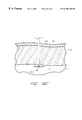
- FIG. 1A is a schematic, cross-sectional view of a human heart, showing a stent in the myocardium of the heart for forming a bypass shunt between the left ventricle and a coronary artery.
- FIG. 1B is an enlarged view of the bypass shunt of FIG. 1 A.
- FIG. 2 is a schematic, partial cross-sectional view of a human heart, showing a stent extending partially into the myocardium from the left ventricle.
- FIG. 3A is a schematic, partial cross-sectional view of a coronary artery adjacent the left ventricle, showing a delivery catheter being advanced through a blockage in the coronary artery.
- FIG. 3B is a schematic, partial cross-sectional view of a coronary artery adjacent the left ventricle, showing a delivery catheter being advanced into the left ventricle.
- FIG. 4A is a schematic side view of a venous access route through a patient's heart.
- FIG. 4B is a schematic, partial cross-sectional view of the venous access route of FIG. 4A between a coronary vein and a coronary artery, showing a delivery catheter being advanced through the coronary vein into the coronary artery.
- FIG. 5 is a schematic, partial cross-sectional view of a coronary artery adjacent the left ventricle, showing a tunnel formed through the myocardium to bypass a blockage in the coronary artery.
- FIG. 6 is a schematic, partial cross-sectional view of a coronary artery adjacent the left ventricle, showing a delivery catheter being advanced through a tunnel formed through the myocardium.
- FIG. 7 is a schematic, partial cross-sectional view of a coronary artery adjacent the left ventricle, showing a Y-shaped tunnel formed through the myocardium to bypass a blockage in the coronary artery.
- FIG. 8 is a partial cross-sectional view of the Y-shaped tunnel of FIG. 7, showing a stent provided therein.
- FIG. 9 is a side view of a delivery catheter carrying two uninflated steering balloons in a blocked coronary artery, with the artery shown partially cut away.
- FIG. 10 is a side view of the delivery catheter of FIG. 9, showing the two balloons partially inflated.
- FIG. 11 is a side view of the delivery catheter of FIG. 9, showing the two balloons fully inflated and a guidewire extending from the distal end of the delivery catheter.
- FIG. 12 is a side view of a delivery catheter with a tip deflecting wire in a blocked coronary artery, with the artery shown partially cut away.
- FIG. 13A is a side view of a delivery catheter having a side port proximal to an inflatable balloon in a blocked coronary artery, with the artery shown partially cut away.
- FIG. 13B is a cross-sectional view of the delivery catheter of FIG. 13A, further showing a guidewire extending therethrough.
- FIG. 14A is a side view of a delivery catheter having a side port distal to an inflatable balloon in a blocked coronary artery, with the artery shown partially cut away.
- FIG. 14B is a cross-sectional view of the delivery catheter of FIG. 14A, further showing a guidewire extending therethrough.
- FIG. 15A is a side view of a delivery catheter having a side port within an inflatable balloon in a blocked coronary artery, with the artery shown partially cut away.
- FIG. 15B is a cross-sectional view of the delivery catheter of FIG. 15A, further showing a guidewire extending through the balloon.
- FIG. 15C is a side view of an alternative embodiment of a delivery catheter having a side port within an inflatable balloon in a blocked coronary artery, with the artery shown partially cut away.
- FIG. 15D is a cross-sectional view of the delivery catheter of FIG. 15C, further showing a guidewire extending through the balloon.
- FIG. 16 is a side view of a delivery catheter having a side port within an inflatable balloon used for treating an aneurysm in a blood vessel, with the vessel shown partially cut away.
- FIG. 17 is a side view of an anchoring guidewire extending through the myocardium, with the myocardium shown partially cut away.
- FIG. 18A is a side view of a guidewire carrying an inflatable balloon on its distal end extending through the myocardium, with the myocardium shown partially cut away.
- FIG. 18B is a side view of the guidewire of FIG. 18A, showing the balloon inflated to anchor the guidewire against the myocardium.
- FIGS. 19A-19C are side views of an alternative embodiment of a guidewire anchored to the inner wall of the myocardium, with the myocardium shown partially cut away.
- FIG. 20 is a side view of a dilation catheter in a coronary artery advanced over a guidewire extending into the myocardium, with the artery and the myocardium shown partially cut away.
- FIG. 21 is a side view of the dilation catheter of FIG. 20 advanced into the myocardium.
- FIG. 22 is a side view of a stent introducer catheter in a coronary artery advanced over a guidewire extending into the myocardium, with the artery and myocardium shown partially cut away.
- FIG. 23 is a side view of the stent introducer catheter of FIG. 22 advanced into the myocardium.
- FIG. 24 is a side view of a drug delivery wire advanced through a coronary artery into the myocardium, with the artery and the myocardium shown partially cut away.
- the preferred embodiments described hereinbelow depict methods and apparatuses for delivering a stent into the myocardium to create a passageway between the left ventricle and coronary artery. It should be appreciated, however, that these embodiments may also be applied to the delivery of stents and other medical devices into other body tissues and vessels, and are particularly applicable for delivering devices at an angled bend relative to the axis of blood flow. In addition, the delivery methods and apparatuses described herein pertain to the placement of stents and other devices partially through the myocardium, as well as for drug delivery and similar applications.
- a coronary artery bypass is accomplished by disposing a stent 10 in a heart wall or myocardium MYO of a patient's heart PH.
- Stent 10 preferably extends from the left ventricle LV of heart PH to a clogged coronary artery CA at a point downstream of a blockage BL to create a shunt 12 therethrough.
- Stent 10 is preferably made of a biocompatible material such as stainless steel or nitinol, although other materials such as Ti, Ti alloys, Ni alloys, Co alloys and biocompatible polymers may also be used.
- Stent 10 preferably has a one way valve 14 to allow blood to flow from the left ventricle LV to the coronary artery CA.
- the stent 10 may elastically deform under the contractive pressure of the heart muscle during systole, the stent remains open to allow blood to pass from the patient's left ventricle LV into the coronary artery CA. During diastole, the blood pumped into coronary artery through shunt 12 is blocked by one-way valve 14 from returning to left ventricle LV. Further details are disclosed in U.S. Pat. No. 5,429,144, the entirety of which is hereby incorporated by reference. Other types of stents may also be used in accordance with the preferred embodiments described herein.
- FIG. 2 illustrates another application for which it is desirable to dispose a stent into the myocardium of a patient.
- a stent 10 is provided partially through the myocardium MYO from the left ventricle LV.
- the stent 10 guides blood directly into the myocardium MYO from the left ventricle to replenish oxygen-deprived heart muscle. Further details are disclosed in the above-referenced U.S. Pat. No. 5,429,144.
- Other applications providing a stent in the myocardium, extending either partially or entirely therethrough and accessed from either the coronary artery or the left ventricle, are also contemplated by the present invention.
- the suitable delivery system (1) provides access to the insertion site adjacent the myocardium; (2) creates an angled bend for transverse insertion of devices into the myocardium; and (3) directs devices into the myocardium for creation of the myocardial passageway.
- the delivery system described herein preferably comprises one or more catheters or guidewires inserted percutaneously into the body, such as through the femoral artery and advanced in the patient's vasculature through the aorta AO, shown in FIG. 1 A. It should be appreciated that the percutaneous approach is not essential to achieve many of the objects of the invention, and therefore, an open-chest or other approach may also be used.
- an exemplary delivery catheter or guidewire 20 which has been advanced percutaneously through the femoral artery and through aorta AO is advanced through the blockage BL in the coronary artery CA.
- the distal tip 22 of the catheter is delivered past the blockage so that it is positioned adjacent to a desired insertion point into the myocardium MYO.
- FIG. 3B shows an alternative access method wherein the catheter 20 is delivered to a position adjacent the myocardium through the left ventricle LV.
- FIGS. 4A and 4B depict an alternative access route used when a blockage in the coronary artery is too large for the catheter to be passed therethrough.
- a delivery catheter 20 enters the body through an access point preferably in the femoral vein (not shown). The catheter is advanced up the vein to the vena cava VC and into the right atrium RA, as shown in FIG. 4 A. Then, the catheter 20 is directed into the coronary sinus CS, and then to the coronary vein CV which runs adjacent to the coronary artery CA.
- the delivery catheter 20 is inserted through the vessel wall VW separating the coronary vein CV from the coronary artery CA.
- Steering of catheter 20 between coronary vein CV and coronary artery CA may be accomplished using the methods and apparatus for turning catheters discussed in further detail below, or other suitable methods.
- the delivery catheter is turned toward the myocardium MYO either for insertion into the myocardium or for directing a guidewire to puncture therethrough.
- Access to the insertion point may also be accomplished by steering the delivery catheter through the coronary artery CA to a point proximal to the blockage, directing the catheter into the coronary vein to bypass the blockage, and reinserting the catheter from the coronary vein into the coronary artery past the blockage, as shown in FIG. 4 B.
- An alternative method of accessing the myocardium MYO when the blockage BL is too large to pass a catheter therethrough employs creating a channel around the blockage.
- a tunnel 24 is created from the coronary artery CA into the myocardium MYO at a point proximal to the blockage BL.
- the tunnel may be created using radiation, lasers, or a surgical drill, or any other suitable methods for creating a tunnel.
- the tunnel 24 extends underneath the blockage BL and connects with the coronary artery CA at a point distal to the blockage BL.
- a delivery catheter 20 is advanced through the coronary artery CA, into the tunnel 24 , and back into the coronary artery CA past the blockage BL. It will be appreciated that other methods for diverting a delivery catheter around a blockage may be used, such as directing the catheter through a shunt into the pericardial space outside the coronary artery.
- tunnel 24 shown in FIG. 6 is described as providing access to a myocardial insertion point for a coronary bypass, it should also be appreciated that this tunneling technique may be useful for obliteration of the blockage BL.
- conventional methods for ablating a blockage only permit access to the blockage from one side.
- a blockage BL can be treated not only from its proximal end, but also from its distal end simultaneously.
- a tunnel is created through the myocardium MYO from a point proximal to a blockage in the coronary artery into the left ventricle.
- a first tunnel 26 is formed proximally of the blockage BL extending into the myocardium MYO beneath the blockage BL.
- the tunnel 26 has a proximal end 28 which opens into the coronary artery CA proximal to the blockage BL, and a distal end 30 within the myocardium MYO beneath the blockage BL.
- a second tunnel 32 extends from the distal end 30 of the first tunnel, with a first branch 34 opening a channel to the coronary artery CA past the location of the blockage BL.
- a second branch 36 of the second tunnel 32 extends downward from the distal end 30 and opens into the left ventricle LV. As illustrated in FIG. 7, a substantially Y-shaped passageway is thereby created through the myocardium MYO to bypass the blockage BL.
- one or more stents 10 are provided in the second tunnel 32 extending between the left ventricle LV and the coronary artery CA.
- This stent 10 opens the myocardial passageway which provides the bypass past blockage BL.
- Positioning of stent 10 in the tunnel 32 is preferably accomplished by advancing a guidewire through the first tunnel 26 and into each branch 34 and 36 of the second tunnel 32 , and then advancing the stent over the guidewire in the manner described below.
- the tunnel 26 between the coronary artery CA and stent 14 is preferably closed at least at distal end 30 , and more preferably, also at proximal end 28 .
- Closure of the tunnel may be accomplished by inserting plugs or other blocking means 38 , or by sealing the tunnel with sutures or similar methods.
- Other suitable closure means include occlusion coils and balloons, adhesives such as cyanoacrylate, and plugs such as sold under the trade name GELFOAM.
- the tunnel may be closed due to the natural contraction of the openings 28 and 30 over time.
- an appropriate delivery system is brought to the site.
- the preferred embodiments described hereinbelow are directed to a delivery system for inserting stents and other medical devices into the myocardium at an angle relative to the axis of blood flow. It should be appreciated that the angle of insertion may be adjusted between 0 and 180 degrees depending on the desired application.
- the delivery systems below describe insertion of devices into the myocardium, these systems also enable angled delivery of medical devices into and through other body lumens and tissues.
- the stent delivery system comprises a catheter which creates an angled bend for insertion of devices into the myocardium MYO.
- FIG. 9 illustrates a delivery catheter 40 which has been advanced into the coronary artery CA past the blockage BL.
- Catheter 40 is an elongate tubular body 42 having a lumen 44 (not shown) extending from a proximal end 46 (not shown) to a distal end 48 .
- the catheter 40 is preferably formed from a flexible biocompatible material such as polymers, stainless steel or nitinol.
- a steering member such as balloon 52
- an anchoring member such as balloon 50
- Balloons 50 and 52 are each preferably mounted on opposite sides of the catheter tubular body 42 , such that anchoring balloon 50 is mounted facing lower wall LW adjacent the myocardium MYO, and steering balloon 52 is mounted facing upper wall UW opposite lower wall LW.
- the anchoring balloon 50 may be mounted concentrically around the tubular body 42 so that inflation of the balloon expands against both the upper and lower walls. It will be appreciated that other devices, such as filters, posts and other expandable members may be used for the anchoring and/or steering members.
- the balloons 50 and 52 remain uninflated. As illustrated in FIG. 10, once the distal tip 48 of the catheter 40 is positioned adjacent the desired insertion site into the myocardium MYO, the balloons 50 and 52 are inflated. Inflation causes the balloons 50 and 52 to cooperate with the walls of the blood vessel to turn the distal end of the catheter. More particularly, in an intermediate state, anchoring balloon 50 inflates against the lower wall LW of the coronary artery CA, while steering balloon 40 presses against the upper wall UW.
- anchoring balloon 50 acts to secure the tubular body 42 within the coronary artery CA.
- Inflation of balloon 50 also preferably causes the catheter 40 to displace in a direction opposite lower wall LW, thereby placing the catheter into a better position for transverse insertion of the distal end 48 into the myocardium MYO.
- Steering balloon 52 is further inflated, causing the distal tip 48 of the tubular body 32 to turn downward towards lower wall LW and myocardium MYO due to the resistance provided by upper wall UW against the balloon.
- FIG. 11 also illustrates the effect that the dual balloon inflation may have on the upper and lower walls of the coronary artery CA.
- the distal tip 48 of catheter 30 is positioned at a substantially transverse angle to the lower wall LW of the coronary artery CA and the myocardium MYO. From this position, the catheter 40 may serve as a guide for the delivery of devices used in creating a myocardial passageway. For example, as shown in FIG.
- a puncture wire or guidewire 100 is advanced through the lumen 44 of tubular body 42 , and then ejected out the distal tip 48 of the catheter 40 to puncture the lower wall LW into the myocardium MYO.
- FIG. 12 illustrates another embodiment for delivering devices transversely into the myocardium MYO of a patient's heart.
- a catheter 54 is shown extending through the coronary artery CA past a blockage BL.
- Catheter 54 comprises an elongate tubular body 56 with a lumen 58 (not shown) extending therethrough from a proximal end 60 (not shown) to a distal end 62 .
- a tip-deflecting puncture wire or pull wire 64 extends from the distal end 62 of the catheter 54 .
- the wire 64 is actuated at the proximal end (not shown) so that it deflects to form a near 90 degree angle relative to the catheter 54 .
- the distal tip 66 of wire 64 is turned so that it is provided adjacent the myocardium MYO. This shape can be locked and the wire 64 is pushed forward through the coronary artery CA and into the wall of the myocardium MYO. As described in further detail below, with the wire 64 in place medical devices are delivered over the wire into the myocardium.
- a delivery catheter is provided with a side port which allows a puncture wire to exit therethrough.
- delivery catheter 70 comprises an elongate tubular body 72 having a proximal end 76 (not shown) and a distal end 78 and a lumen 74 (not shown) extending at least partially therethrough.
- an expandable or anchoring member such as inflatable balloon 80 , which is inflated to maintain the position of the catheter 70 within the artery.
- the balloon 80 is preferably a perfusion type balloon having a channel 86 to allow blood flow through the artery during the procedure.
- filters or other devices which allow blood flow through the artery while anchoring the catheter 70 may also be utilized.
- Perfusion may also be provided through a lumen in the tubular body 72 .
- a distal opening or side port exit 82 is provided through the wall of tubular body 72 near the distal end of the catheter extending from lumen 74 .
- the side port 82 may be located either proximal to the balloon 80 , as in FIG. 13A, or distal to the balloon 80 , as in FIG. 14 A.
- Catheter 70 is delivered through the vasculature until the side port exit 82 is past the location of the blockage BL. Prior to balloon inflation, the catheter 70 is turned about its longitudinal axis so that the opening 82 faces the myocardium.
- FIGS. 13B and 14B illustrate the pathway for a guidewire 100 to pass through the lumen 74 of catheter 70 .
- guidewire 100 extends through the lumen 74 toward the distal end 78 of the catheter. Proximal to balloon 80 , the lumen 74 turns downward toward side port exit 82 . Thus, before guidewire 100 reaches the proximal end of balloon 80 , the guidewire 100 is directed out of the side port 82 toward the lower wall LW of the coronary artery CA.
- a second lumen 84 is also provided within catheter 70 to direct inflation fluid to balloon 80 .
- FIG. 14B shows substantially the same configuration except that the lumen 74 extends through the balloon 80 such that the side port exit 82 is located distal to the balloon 80 .
- Guidewire 100 therefore extends through lumen 74 and out side port exit 82 toward the lower wall LW.
- a second lumen 84 is provided through tubular body 72 to direct inflation fluid into the balloon 80 .
- the side port 82 is located on an exterior surface of the balloon 80 .
- balloon 80 is inflated.
- balloon 80 preferably comprises a perfusion channel 86 extending from the proximal end to the distal end of the balloon 80 to allow blood to flow through the vessel.
- a lumen 74 is provided through the catheter 70 which extends into balloon 80 and turns downward into side port exit 82 .
- the catheter 70 also has a lumen 84 for inflation of balloon 80 .
- Guidewire 100 is advanced through lumen 74 and out side port exit 82 into the myocardium MYO.
- FIGS. 15C and 15D illustrate yet another embodiment of a delivery catheter with a side port exit.
- the catheter 70 comprises an elongate tubular body 72 having a lumen 74 extending from a proximal end 76 (not shown) to distal end 78 .
- This lumen 74 is in fluid communication with balloon 80 to provide inflation of the balloon.
- balloon 80 When inflated, balloon 80 has a perfusion lumen 86 which allows blood to perfuse therethrough.
- the balloon 80 also has a guide lumen 88 extending therethrough which, when inflated, extends from a proximal end of the balloon to the lower wall LW.
- a guidewire 100 may then be inserted through the guide lumen 88 and out side port exit 82 into the myocardium MYO.
- FIG. 15A-15D are useful not only for disposing a stent into the myocardium but also for the treatment of aneurysms.
- Aneurysms are typically treated by introducing embolic elements to fill the aneurysm.
- FIG. 16 illustrates a method for solving this problem using the delivery catheter 70 described above with respect to FIGS. 15C and 15D.
- a catheter 70 carrying inflatable balloon 80 is advanced such that the balloon 80 is adjacent the aneurysm 92 .
- the balloon 80 is inflated to substantially enclose the aneurysm 92 .
- a wire 94 or other embolic element is advanced through the guide lumen 88 of balloon 80 and out side port 82 .
- the wire 94 fills up the aneurysm 92 , and is maintained in the aneurysm due to the fact that the balloon 80 encloses the aneurysm to prevent wire 94 from extending into the vessel.
- the wire 94 or other embolic element may also be delivered through a lumen 74 , as shown with respect to the embodiment in FIG. 15 B.
- the embodiments described above are directed primarily to providing a guidewire 100 into the patient's myocardium. As described in further detail below, this guidewire is used for delivering medical devices into the myocardium. However, it should be appreciated that many of the embodiments described above may also be used in conjunction with other methods for creating a passageway through the myocardium. For instance, a delivery catheter, such as described above, may be used for delivering a surgical drill or other tissue penetrating device ejected from the distal end thereof. This approach would be useful, for instance, in creating a tunnel through the myocardium as described above. Alternatively, a Seldinger wire may be ejected from the distal end of the delivery catheter. Further details are described in the above-referenced U.S. Pat. No. 5,429,144.
- a puncture device such as guidewire 100 is directed into the myocardium 100 using any of the preferred methods described above.
- Guidewire 100 preferably has a proximal end 102 (not shown) which remains outside the patient's body, and a distal end 104 which is inserted through a delivery catheter as described above. Where the delivery catheter is provided through the coronary artery, the guidewire is advanced in one embodiment until the distal end 104 of the guidewire enters the left ventricle. Alternatively, where it is desired that a stent or other device extend only partially into the myocardium, the guidewire 100 need not extend all the way through to the left ventricle.
- the distal tip 104 of the guidewire 100 is preferably made of a radiopaque material that can be visualized by the physician by an available method, such as fluoroscopy.
- the distal end of the guidewire 100 is preferably formed such that it is easily advanced but is difficult to pull back through the tissue.
- one embodiment of the distal tip 104 comprises one or more barbs 106 extending from the tip in a type of “multi-winged arrowhead” configuration. These barbs allow the guidewire to be advanced distally into the myocardium but require more force to pull the guidewire 100 proximally out of the myocardium, thus creating an effective anchor.
- FIG. 18A shows another embodiment wherein a guidewire 100 carries an expandable member such as balloon 110 on its distal end.
- an expandable member such as balloon 110 on its distal end.
- Use of an expandable member reduces damage to the myocardium during subsequent retraction of the wire 100 .
- FIG. 18B once the balloon 110 reaches the left ventricle LV, the balloon 110 is inflated. The balloon is then preferably pulled proximally back to the ventricle wall to anchor and secure the guidewire 100 in place.
- FIGS. 19A-19C show an expandable guidewire 100 extending through and actuated to anchor the guidewire within the myocardium MYO.
- a guidewire 100 is shown advanced through the myocardium MYO.
- Guidewire 100 is provided with an expandable device 112 on distal end 104 which may be actuated by an operator at the proximal end of the guidewire outside of the patient. Actuating of the device may be accomplished by using a shape memory material such as nitinol and heating the material above its transformation temperature. Alternatively, the guidewire may be mechanically actuated to assume the desired shape.
- FIG. 19B shows the guidewire 100 partially actuated at its distal end 104 to expand the device 112 into an anchorable shape.
- FIG. 19C shows the expandable device 112 fully actuated to anchor the guidewire 100 against the ventricle wall. Other types of anchoring and expandable members may also be used to secure the guidewire 100 .
- the delivery catheter may be removed without displacing the guidewire inserted through the myocardium. Then, with the guidewire 100 anchored in place, catheters used in creating and stenting the passageway or other medical devices may be provided into the myocardium. Alternatively, the delivery catheter may remain within the blood vessel and other catheters or medical devices may be advanced over the guidewire and through the delivery catheter. Furthermore, an expandable member such as a balloon may be provided on the delivery catheter or on the guidewire 100 to anchor the catheter or guidewire to the wall of the blood vessel to provide for more secure deployment of medical devices into the myocardium.
- an expandable member such as a balloon may be provided on the delivery catheter or on the guidewire 100 to anchor the catheter or guidewire to the wall of the blood vessel to provide for more secure deployment of medical devices into the myocardium.
- the anchoring of the guidewire 100 within the myocardium MYO allows for the delivery of devices into the myocardium for creation of a myocardial passageway.
- the anchoring of the guidewire 100 facilitates advancement of over-the-wire catheters such as introducer catheters into the myocardium by employing a push-pull mechanism.
- the guidewire 100 may be pulled proximally by an operator from outside of the body.
- the anchoring member at the distal end of the guidewire whether a balloon, barb, or other member, prevents the guidewire 100 from exiting the myocardium MYO.
- a delivery catheter or other over-the-wire device may be pushed into the myocardium MYO, assisted by the pulling force of the anchoring member toward the catheter.
- the anchoring member also assists in placement of an over-the-wire catheter in the myocardium by preventing the catheter from extending beyond the location of the anchoring member.
- a catheter 120 having a dilation balloon 122 is advanced over guidewire 100 , into the myocardium MYO, as shown in FIG. 21 .
- the anchored balloon 110 acts as a barrier to advancement of balloon 122 , which is subsequently inflated within myocardium MYO to expand a myocardial passageway.
- the balloon 122 is then deflated and the catheter 120 removed. The process may be repeated with successively larger dilation balloons to form a passageway of desired size.
- the catheter 120 After inflation of the largest desired dilation balloon, the catheter 120 is withdrawn and a stent introducer catheter 130 is advanced over wire 100 , as shown in FIG. 22 .
- the catheter 130 has an inflatable balloon 132 mounted on its distal end for deploying a stent 134 carried by balloon 132 .
- balloon 132 Upon the positioning of balloon 132 inside the myocardium MYO, balloon 132 is inflated, as shown in FIG. 23, to assist in an initial expansion of stent 134 in opposition to the compressive forces of the heart muscle.
- balloon 132 Upon the desired disposition of stent 134 , balloon 132 is deflated and catheter 130 and wire 100 are withdrawn, leaving stent 134 in place to provide a coronary bypass between ventricle LV and artery CA.
- the guidewire such as described above delivered into the myocardium MYO may also be used for delivering drugs into the myocardium.
- a guidewire 140 is advanced partially into the myocardium using any of the methods described above.
- the guidewire 140 comprises a tubular body 142 having a lumen 148 (not shown) extending from a proximal end 144 (not shown) to a distal end 146 .
- the guidewire may be angled using the turning methods described above to provide the distal end of the guidewire at a desired position within the myocardium for drug delivery.
- Drug delivery fluids 150 are ejected from the distal and 146 into the myocardium.
- anchoring means as described above may be provided.
- the guidewire 140 may contain a plurality of ports 152 along the tubular body 142 near the distal end 146 .
Abstract
Description
Claims (38)
Priority Applications (11)
| Application Number | Priority Date | Filing Date | Title |
|---|---|---|---|
| US09/150,181 US6196230B1 (en) | 1998-09-10 | 1998-09-10 | Stent delivery system and method of use |
| US09/368,868 US6261304B1 (en) | 1998-09-10 | 1999-08-04 | Delivery methods for left ventricular conduit |
| EP99951403A EP1112102A1 (en) | 1998-09-10 | 1999-09-10 | Tunneling catheter system for artificial ventricular wall conduit |
| JP2000619496A JP2003500121A (en) | 1998-09-10 | 1999-09-10 | Ventricular wall conduction catheter for artificial conduit |
| AU63845/99A AU6384599A (en) | 1998-09-10 | 1999-09-10 | Tunneling catheter system for artificial ventricular wall conduit |
| US09/710,884 US6409751B1 (en) | 1998-09-10 | 2000-11-14 | Stent delivery system and method of use |
| US09/796,590 US6387119B2 (en) | 1998-09-10 | 2001-03-02 | Delivery methods for left ventricular conduit |
| US09/891,663 US20010039445A1 (en) | 1998-09-10 | 2001-06-27 | Stent delivery system and method of use |
| US10/092,916 US6694983B2 (en) | 1998-09-10 | 2002-03-08 | Delivery methods for left ventricular conduit |
| US10/625,536 US20040186507A1 (en) | 1998-09-10 | 2003-07-24 | Stent delivery system and method of use |
| US10/727,543 US20040118415A1 (en) | 1998-09-10 | 2003-12-05 | Delivery methods for left ventricular conduit |
Applications Claiming Priority (1)
| Application Number | Priority Date | Filing Date | Title |
|---|---|---|---|
| US09/150,181 US6196230B1 (en) | 1998-09-10 | 1998-09-10 | Stent delivery system and method of use |
Related Child Applications (2)
| Application Number | Title | Priority Date | Filing Date |
|---|---|---|---|
| US09/368,868 Continuation-In-Part US6261304B1 (en) | 1998-09-10 | 1999-08-04 | Delivery methods for left ventricular conduit |
| US09/710,884 Continuation US6409751B1 (en) | 1998-09-10 | 2000-11-14 | Stent delivery system and method of use |
Publications (1)
| Publication Number | Publication Date |
|---|---|
| US6196230B1 true US6196230B1 (en) | 2001-03-06 |
Family
ID=22533422
Family Applications (4)
| Application Number | Title | Priority Date | Filing Date |
|---|---|---|---|
| US09/150,181 Expired - Fee Related US6196230B1 (en) | 1998-09-10 | 1998-09-10 | Stent delivery system and method of use |
| US09/710,884 Expired - Fee Related US6409751B1 (en) | 1998-09-10 | 2000-11-14 | Stent delivery system and method of use |
| US09/891,663 Abandoned US20010039445A1 (en) | 1998-09-10 | 2001-06-27 | Stent delivery system and method of use |
| US10/625,536 Abandoned US20040186507A1 (en) | 1998-09-10 | 2003-07-24 | Stent delivery system and method of use |
Family Applications After (3)
| Application Number | Title | Priority Date | Filing Date |
|---|---|---|---|
| US09/710,884 Expired - Fee Related US6409751B1 (en) | 1998-09-10 | 2000-11-14 | Stent delivery system and method of use |
| US09/891,663 Abandoned US20010039445A1 (en) | 1998-09-10 | 2001-06-27 | Stent delivery system and method of use |
| US10/625,536 Abandoned US20040186507A1 (en) | 1998-09-10 | 2003-07-24 | Stent delivery system and method of use |
Country Status (1)
| Country | Link |
|---|---|
| US (4) | US6196230B1 (en) |
Cited By (141)
| Publication number | Priority date | Publication date | Assignee | Title |
|---|---|---|---|---|
| US20020016597A1 (en) * | 2000-08-02 | 2002-02-07 | Dwyer Clifford J. | Delivery apparatus for a self-expanding stent |
| US6387119B2 (en) | 1998-09-10 | 2002-05-14 | Percardia, Inc. | Delivery methods for left ventricular conduit |
| US6409751B1 (en) * | 1998-09-10 | 2002-06-25 | Percardia, Inc. | Stent delivery system and method of use |
| US20020092535A1 (en) * | 1996-06-19 | 2002-07-18 | Wilk Patent Development Corp. | Coronary artery by-pass method |
| US20020099404A1 (en) * | 2001-01-25 | 2002-07-25 | Mowry David H. | Intravascular ventriculocoronary artery bypass delivery modalities |
| US20030074007A1 (en) * | 2001-10-12 | 2003-04-17 | Rosengart Todd K. | Method and apparatus for performing an anastamosis |
| US6562019B1 (en) * | 1999-09-20 | 2003-05-13 | Stereotaxis, Inc. | Method of utilizing a magnetically guided myocardial treatment system |
| US6582444B2 (en) | 1999-08-04 | 2003-06-24 | Percardia, Inc. | Blood flow conduit delivery system and method of use |
| US20030135260A1 (en) * | 2002-01-16 | 2003-07-17 | Kohler Robert Edward | Encased implant and methods |
| US6605113B2 (en) | 1999-08-04 | 2003-08-12 | Percardia Inc. | Vascular graft bypass |
| US6605053B1 (en) | 1999-09-10 | 2003-08-12 | Percardia, Inc. | Conduit designs and related methods for optimal flow control |
| US20030158509A1 (en) * | 2002-02-13 | 2003-08-21 | Tweden Katherine S. | Cardiac implant and methods |
| US6610100B2 (en) | 1998-09-10 | 2003-08-26 | Percardia, Inc. | Designs for left ventricular conduit |
| US20030185860A1 (en) * | 2002-04-01 | 2003-10-02 | Allergan Sales, Inc. | Methods for treating cardiovasular diseases with botulinum toxin |
| US6638237B1 (en) | 1999-08-04 | 2003-10-28 | Percardia, Inc. | Left ventricular conduits and methods for delivery |
| US6641610B2 (en) | 1998-09-10 | 2003-11-04 | Percardia, Inc. | Valve designs for left ventricular conduits |
| US20030216801A1 (en) * | 2002-05-17 | 2003-11-20 | Heartstent Corporation | Transmyocardial implant with natural vessel graft and method |
| US6651670B2 (en) * | 1998-02-13 | 2003-11-25 | Ventrica, Inc. | Delivering a conduit into a heart wall to place a coronary vessel in communication with a heart chamber and removing tissue from the vessel or heart wall to facilitate such communication |
| US20030220661A1 (en) * | 2002-05-21 | 2003-11-27 | Heartstent Corporation | Transmyocardial implant delivery system |
| US6669686B1 (en) * | 1999-07-20 | 2003-12-30 | Ajoy Inder Singh | Method and apparatus for arterial ablation |
| US20040015151A1 (en) * | 2002-07-22 | 2004-01-22 | Chambers Technologies, Llc | Catheter with flexible tip and shape retention |
| US20040049171A1 (en) * | 2002-09-09 | 2004-03-11 | Heartstent Corporation | Device for placing transmyocardial implant |
| US20040097988A1 (en) * | 1999-01-15 | 2004-05-20 | Ventrica, Inc. | Methods and devices for placing a conduit in fluid communication with a target vessel |
| US6743219B1 (en) | 2000-08-02 | 2004-06-01 | Cordis Corporation | Delivery apparatus for a self-expanding stent |
| US20040147868A1 (en) * | 2003-01-27 | 2004-07-29 | Earl Bardsley | Myocardial implant with collar |
| US20040168691A1 (en) * | 1998-02-13 | 2004-09-02 | Sharkawy A. Adam | Conduits for use in placing a target vessel in fluid communication with source of blood |
| US20040210190A1 (en) * | 2001-08-16 | 2004-10-21 | Percardia, Inc. | Interventional diagnostic catheter and a method for using a catheter to access artificial cardiac shunts |
| US6814751B2 (en) | 2001-10-12 | 2004-11-09 | Rosengart Todd K | Method and apparatus for performing an anastamosis |
| US20050015110A1 (en) * | 2003-07-18 | 2005-01-20 | Fogarty Thomas J. | Embolization device and a method of using the same |
| US20050021124A1 (en) * | 2003-07-22 | 2005-01-27 | Brendan Cunniffe | Stents and stent delivery system |
| US20050033401A1 (en) * | 2003-07-17 | 2005-02-10 | Brendan Cunniffe | Methods and devices for placing a fistula device in fluid communication with a target vessel |
| US20050043781A1 (en) * | 1998-02-13 | 2005-02-24 | Mark Foley | Methods and devices providing transmyocardial blood flow to the arterial vascular system of the heart |
| US6916304B2 (en) | 1999-05-04 | 2005-07-12 | Percardia, Inc. | Transmyocardial implant with flow reduction |
| US6929009B2 (en) * | 1996-08-26 | 2005-08-16 | Medtronic Vascular, Inc. | Method and apparatus for transmyocardial direct coronary revascularization |
| US20050273050A1 (en) * | 2002-11-19 | 2005-12-08 | Nihon University | Balloon catheter and device for injecting medical treatment method |
| US20060212112A1 (en) * | 2004-07-22 | 2006-09-21 | Nellix, Inc. | Graft systems having filling structures supported by scaffolds and methods for their use |
| US20060216313A1 (en) * | 1999-08-10 | 2006-09-28 | Allergan, Inc. | Methods for treating a stricture with a botulinum toxin |
| US20060292206A1 (en) * | 2001-11-26 | 2006-12-28 | Kim Steven W | Devices and methods for treatment of vascular aneurysms |
| US20070010781A1 (en) * | 2005-06-27 | 2007-01-11 | Venkataramana Vijay | Implantable aorto-coronary sinus shunt for myocardial revascularization |
| US20070055344A1 (en) * | 1998-02-13 | 2007-03-08 | Gittings Darin C | Devices and methods for use in performing transmyocardial coronary bypass |
| US20070150041A1 (en) * | 2005-12-22 | 2007-06-28 | Nellix, Inc. | Methods and systems for aneurysm treatment using filling structures |
| US20070276477A1 (en) * | 2006-05-24 | 2007-11-29 | Nellix, Inc. | Material for creating multi-layered films and methods for making the same |
| US20070282366A1 (en) * | 2006-05-30 | 2007-12-06 | Farhad Khosravi | Materials formable in situ within a medical device |
| US20070290497A1 (en) * | 2006-06-15 | 2007-12-20 | Arendt Albert L | Children's ride-on vehicles with reconfigured bodies and methods for forming the same |
| US20080018016A1 (en) * | 1999-09-10 | 2008-01-24 | Rapacki Alan R | Manufacturing conduits for use in placing a target vessel in fluid communication with a source of blood |
| US20080103479A1 (en) * | 2001-06-11 | 2008-05-01 | Eric Cheng | Delivery system using balloon catheter with side opening and method |
| US20080171101A1 (en) * | 1999-09-10 | 2008-07-17 | Rapacki Alan R | Manufacturing conduits for use in placing a target vessel in fluid communication with a source of blood |
| US20090093857A1 (en) * | 2006-12-28 | 2009-04-09 | Markowitz H Toby | System and method to evaluate electrode position and spacing |
| US20090105748A1 (en) * | 2002-11-12 | 2009-04-23 | Thomas J. Fogarty | Embolization device and a method of using the same |
| US7530988B2 (en) | 2004-07-22 | 2009-05-12 | Nellix, Inc. | Methods and systems for endovascular aneurysm treatment |
| US20090125100A1 (en) * | 2007-11-13 | 2009-05-14 | Cook Incorporated | Intraluminal Bypass Prosthesis and Prosthesis Delivery and Deployment Kit |
| US20090171432A1 (en) * | 2005-12-22 | 2009-07-02 | Von Segesser Ludwig K | Stent-valves for valve replacement and associated methods and systems for surgery |
| US20090198177A1 (en) * | 2008-02-04 | 2009-08-06 | Sawhney Amarpreet S | Surgical delivery system for medical sealant |
| US20090262980A1 (en) * | 2008-04-18 | 2009-10-22 | Markowitz H Toby | Method and Apparatus for Determining Tracking a Virtual Point Defined Relative to a Tracked Member |
| US20090264747A1 (en) * | 2008-04-18 | 2009-10-22 | Markowitz H Toby | Determining and illustrating tracking system members |
| US20090262979A1 (en) * | 2008-04-18 | 2009-10-22 | Markowitz H Toby | Determining a Material Flow Characteristic in a Structure |
| US20090262992A1 (en) * | 2008-04-18 | 2009-10-22 | Markowitz H Toby | Method And Apparatus For Mapping A Structure |
| US20090264984A1 (en) * | 2001-12-20 | 2009-10-22 | Trivascular2, Inc. | Advanced endovascular graft |
| US20090264739A1 (en) * | 2008-04-18 | 2009-10-22 | Markowitz H Toby | Determining a position of a member within a sheath |
| US20090297001A1 (en) * | 2008-04-18 | 2009-12-03 | Markowitz H Toby | Method And Apparatus For Mapping A Structure |
| US20090319029A1 (en) * | 2008-06-04 | 2009-12-24 | Nellix, Inc. | Docking apparatus and methods of use |
| US20090326629A1 (en) * | 2002-09-24 | 2009-12-31 | Ronald Alan Drake | Lead delivery device and method |
| US20090326551A1 (en) * | 2008-06-27 | 2009-12-31 | Medtronic, Inc. | Lead delivery device and method |
| US20090326631A1 (en) * | 2008-06-27 | 2009-12-31 | Medtronic,Inc. | Lead delivery device and method |
| US20090326550A1 (en) * | 2002-09-24 | 2009-12-31 | Medtronic, Inc. | Lead delivery device and method |
| US20090326630A1 (en) * | 2008-06-27 | 2009-12-31 | Lindsey Marie Tobin | Lead delivery device and method |
| US20100004728A1 (en) * | 2008-02-13 | 2010-01-07 | Nellix, Inc. | Graft endoframe having axially variable characteristics |
| US20100016863A1 (en) * | 2008-06-27 | 2010-01-21 | Medtronic, Inc. | Lead delivery device and method |
| US20100016864A1 (en) * | 2002-09-24 | 2010-01-21 | Medtronic, Inc. | Lead delivery device and method |
| US20100036360A1 (en) * | 2008-04-25 | 2010-02-11 | Nellix, Inc. | Stent graft delivery system |
| US7666220B2 (en) | 2005-07-07 | 2010-02-23 | Nellix, Inc. | System and methods for endovascular aneurysm treatment |
| US7704222B2 (en) | 1998-09-10 | 2010-04-27 | Jenavalve Technology, Inc. | Methods and conduits for flowing blood from a heart chamber to a blood vessel |
| US20110022157A1 (en) * | 2007-10-25 | 2011-01-27 | Jacques Essinger | Stents, Valved-Stents, and Methods and Systems for Delivery Thereof |
| US20110106203A1 (en) * | 2009-10-30 | 2011-05-05 | Medtronic, Inc. | System and method to evaluate electrode position and spacing |
| US20110224655A1 (en) * | 2008-09-11 | 2011-09-15 | Asirvatham Samuel J | Central core multifunctional cardiac devices |
| US8066755B2 (en) | 2007-09-26 | 2011-11-29 | Trivascular, Inc. | System and method of pivoted stent deployment |
| US8083789B2 (en) | 2007-11-16 | 2011-12-27 | Trivascular, Inc. | Securement assembly and method for expandable endovascular device |
| CN102309809A (en) * | 2010-07-09 | 2012-01-11 | 同济大学 | The neostomy system |
| US8135467B2 (en) | 2007-04-18 | 2012-03-13 | Medtronic, Inc. | Chronically-implantable active fixation medical electrical leads and related methods for non-fluoroscopic implantation |
| US8175681B2 (en) | 2008-12-16 | 2012-05-08 | Medtronic Navigation Inc. | Combination of electromagnetic and electropotential localization |
| US8226701B2 (en) | 2007-09-26 | 2012-07-24 | Trivascular, Inc. | Stent and delivery system for deployment thereof |
| US8241346B2 (en) | 2001-12-20 | 2012-08-14 | Trivascular, Inc. | Endovascular graft and method of delivery |
| US8328861B2 (en) | 2007-11-16 | 2012-12-11 | Trivascular, Inc. | Delivery system and method for bifurcated graft |
| US20130006173A1 (en) * | 2011-06-30 | 2013-01-03 | Alvarez Jeffery B | Reentry Catheter and Method Thereof |
| US20130150880A1 (en) * | 2011-12-09 | 2013-06-13 | Boston Scientific Scimed, Inc. | Subintimal recanalization with bio-absorbable stent |
| US8494614B2 (en) | 2009-08-31 | 2013-07-23 | Regents Of The University Of Minnesota | Combination localization system |
| US8494613B2 (en) | 2009-08-31 | 2013-07-23 | Medtronic, Inc. | Combination localization system |
| US8663309B2 (en) | 2007-09-26 | 2014-03-04 | Trivascular, Inc. | Asymmetric stent apparatus and method |
| US8801768B2 (en) | 2011-01-21 | 2014-08-12 | Endologix, Inc. | Graft systems having semi-permeable filling structures and methods for their use |
| US8945199B2 (en) | 2008-06-04 | 2015-02-03 | Nellix, Inc. | Sealing apparatus and methods of use |
| US8961501B2 (en) | 2010-09-17 | 2015-02-24 | Incept, Llc | Method for applying flowable hydrogels to a cornea |
| US8992595B2 (en) | 2012-04-04 | 2015-03-31 | Trivascular, Inc. | Durable stent graft with tapered struts and stable delivery methods and devices |
| US9113999B2 (en) | 2002-09-20 | 2015-08-25 | Nellix, Inc. | Methods for deploying a positioning anchor with a stent-graft |
| US9162038B2 (en) | 2011-04-11 | 2015-10-20 | The Spectranetics Corporation | Needle and guidewire holder |
| US9277923B2 (en) | 2009-03-31 | 2016-03-08 | Barking Havering & Redbridge Hospitals Nhs Trust | Balloon assisted occlusion of aneurysms |
| US9289536B2 (en) | 2013-03-14 | 2016-03-22 | Endologix, Inc. | Method for forming materials in situ within a medical device |
| US9393100B2 (en) | 2010-11-17 | 2016-07-19 | Endologix, Inc. | Devices and methods to treat vascular dissections |
| US9393133B2 (en) | 2011-02-18 | 2016-07-19 | Piolax Medical Devices, Inc. | Abdominal cavity-vein shunt stent |
| US9415195B2 (en) | 2011-04-06 | 2016-08-16 | Engologix, Inc. | Method and system for treating aneurysms |
| US9498363B2 (en) | 2012-04-06 | 2016-11-22 | Trivascular, Inc. | Delivery catheter for endovascular device |
| US20170014561A1 (en) * | 2014-03-17 | 2017-01-19 | Nuheart As | Transcatheter insertion device and method |
| US9579103B2 (en) | 2009-05-01 | 2017-02-28 | Endologix, Inc. | Percutaneous method and device to treat dissections |
| US20170079671A1 (en) * | 2015-09-22 | 2017-03-23 | Medtronic Vascular, Inc. | Occlusion Bypassing Apparatus With a Re-Entry Needle and a Stabilization Tube |
| US9615912B2 (en) | 2003-02-12 | 2017-04-11 | Thomas J. Fogarty | Intravascular implants and methods of using the same |
| US9775969B2 (en) | 2011-06-30 | 2017-10-03 | The Spectranetics Corporation | Reentry catheter and method thereof |
| WO2017183014A1 (en) * | 2016-04-18 | 2017-10-26 | Capsos Medical Limited | A branched balloon catheter |
| US9814862B2 (en) | 2011-06-30 | 2017-11-14 | The Spectranetics Corporation | Reentry catheter and method thereof |
| US9855100B2 (en) | 2008-04-02 | 2018-01-02 | The Spectranetics Corporation | Liquid light-guide catheter with optically diverging tip |
| US10039905B1 (en) | 2015-10-07 | 2018-08-07 | Edwards Lifesciences Corporation | Systems for deploying an expandable cardiac shunt |
| US10092357B2 (en) | 2008-07-21 | 2018-10-09 | The Spectranetics Corporation | Tapered liquid light guide |
| US10143824B2 (en) | 2014-03-05 | 2018-12-04 | Invatec S.P.A. | Catheter assemblies and methods for stabilizing a catheter assembly within a subintimal space |
| US10159557B2 (en) | 2007-10-04 | 2018-12-25 | Trivascular, Inc. | Modular vascular graft for low profile percutaneous delivery |
| US10258464B2 (en) | 2012-03-22 | 2019-04-16 | Symetis Sa | Transcatheter stent-valves |
| US10327791B2 (en) | 2015-10-07 | 2019-06-25 | Medtronic Vascular, Inc. | Occlusion bypassing apparatus with a re-entry needle and a distal stabilization balloon |
| US10335528B2 (en) | 2016-10-07 | 2019-07-02 | Nuheart As | Transcatheter method and system for the delivery of intracorporeal devices |
| US10350395B2 (en) * | 2017-06-23 | 2019-07-16 | Cook Medical Technologies Llc | Introducer for lumen support or dilation |
| US10376359B2 (en) | 2009-11-02 | 2019-08-13 | Symetis Sa | Aortic bioprosthesis and systems for delivery thereof |
| US10456557B2 (en) | 2014-08-14 | 2019-10-29 | Invatec S.P.A. | Occlusion bypassing apparatus with varying flexibility and methods for bypassing an occlusion in a blood vessel |
| US10537672B2 (en) | 2016-10-07 | 2020-01-21 | Nuheart As | Transcatheter device and system for the delivery of intracorporeal devices |
| US10537670B2 (en) | 2017-04-28 | 2020-01-21 | Nuheart As | Ventricular assist device and method |
| EP3610810A1 (en) * | 2006-11-21 | 2020-02-19 | Bridgepoint Medical, Inc. | Endovascular devices for exploiting intramural space |
| US10716662B2 (en) | 2007-08-21 | 2020-07-21 | Boston Scientific Limited | Stent-valves for valve replacement and associated methods and systems for surgery |
| US10772717B2 (en) | 2009-05-01 | 2020-09-15 | Endologix, Inc. | Percutaneous method and device to treat dissections |
| US10888646B2 (en) | 2017-04-28 | 2021-01-12 | Nuheart As | Ventricular assist device and method |
| US10893847B2 (en) | 2015-12-30 | 2021-01-19 | Nuheart As | Transcatheter insertion system |
| US10993805B2 (en) | 2008-02-26 | 2021-05-04 | Jenavalve Technology, Inc. | Stent for the positioning and anchoring of a valvular prosthesis in an implantation site in the heart of a patient |
| US11065138B2 (en) | 2016-05-13 | 2021-07-20 | Jenavalve Technology, Inc. | Heart valve prosthesis delivery system and method for delivery of heart valve prosthesis with introducer sheath and loading system |
| CN113301941A (en) * | 2018-10-31 | 2021-08-24 | 安可布鲁恩公司 | Systems and methods for controlled delivery of medical devices into a patient |
| US11185405B2 (en) | 2013-08-30 | 2021-11-30 | Jenavalve Technology, Inc. | Radially collapsible frame for a prosthetic valve and method for manufacturing such a frame |
| US11197754B2 (en) | 2017-01-27 | 2021-12-14 | Jenavalve Technology, Inc. | Heart valve mimicry |
| US11207176B2 (en) | 2012-03-22 | 2021-12-28 | Boston Scientific Scimed, Inc. | Transcatheter stent-valves and methods, systems and devices for addressing para-valve leakage |
| US11298444B2 (en) | 2005-04-01 | 2022-04-12 | Trivascular, Inc. | Non-degradable, low swelling, water soluble radiopaque hydrogel polymer |
| US11337800B2 (en) | 2015-05-01 | 2022-05-24 | Jenavalve Technology, Inc. | Device and method with reduced pacemaker rate in heart valve replacement |
| US11357624B2 (en) | 2007-04-13 | 2022-06-14 | Jenavalve Technology, Inc. | Medical device for treating a heart valve insufficiency |
| US11517431B2 (en) | 2005-01-20 | 2022-12-06 | Jenavalve Technology, Inc. | Catheter system for implantation of prosthetic heart valves |
| US11564794B2 (en) | 2008-02-26 | 2023-01-31 | Jenavalve Technology, Inc. | Stent for the positioning and anchoring of a valvular prosthesis in an implantation site in the heart of a patient |
| US11589981B2 (en) | 2010-05-25 | 2023-02-28 | Jenavalve Technology, Inc. | Prosthetic heart valve and transcatheter delivered endoprosthesis comprising a prosthetic heart valve and a stent |
| US11638638B2 (en) | 2009-12-30 | 2023-05-02 | Endologix Llc | Filling structure for a graft system and methods of use |
| WO2023211456A1 (en) * | 2022-04-29 | 2023-11-02 | Bard Peripheral Vascular, Inc. | Perfusion balloon catheter and related methods |
| US11931523B2 (en) | 2008-06-27 | 2024-03-19 | Medtronic, Inc. | Lead delivery device and method |
| US11957608B2 (en) | 2021-02-01 | 2024-04-16 | Nellix, Inc. | Graft systems having filling structures supported by scaffolds and methods for their use |
Families Citing this family (40)
| Publication number | Priority date | Publication date | Assignee | Title |
|---|---|---|---|---|
| JP2002524196A (en) * | 1998-09-10 | 2002-08-06 | パーカーディア,インコーポレイティド | Transmyocardial shunt for left ventricular revascularization and its mounting mechanism |
| ATE322230T1 (en) * | 1998-09-10 | 2006-04-15 | Percardia Inc | TMR DEVICE |
| US6926689B2 (en) * | 2002-03-13 | 2005-08-09 | Albertus Scheule | Aortic balloon occlusion cannula |
| US20060089588A1 (en) * | 1999-09-13 | 2006-04-27 | Albertus Scheule | Aortic balloon occlusion cannula |
| US6854467B2 (en) * | 2000-05-04 | 2005-02-15 | Percardia, Inc. | Methods and devices for delivering a ventricular stent |
| US7316709B2 (en) * | 2004-01-13 | 2008-01-08 | Advanced Cardiovascular Systems, Inc. | Balloon catheter having a textured member for enhancing balloon or stent retention |
| US20060030871A1 (en) * | 2004-08-05 | 2006-02-09 | Matthew Hain | Vascular tunneler |
| US7879050B2 (en) * | 2005-03-23 | 2011-02-01 | Wilk Peter J | Trans-vascular surgical method and associated device |
| US20060271154A1 (en) * | 2005-05-25 | 2006-11-30 | Prescient Medical, Inc. | Methods and systems for treating vulnerable plaque |
| EP1898811B1 (en) | 2005-06-30 | 2019-03-06 | Rox Medical, Inc. | Devices and systems for creation of a peripherally located fistula |
| US9149378B2 (en) | 2005-08-02 | 2015-10-06 | Reva Medical, Inc. | Axially nested slide and lock expandable device |
| US7914574B2 (en) | 2005-08-02 | 2011-03-29 | Reva Medical, Inc. | Axially nested slide and lock expandable device |
| US20070043381A1 (en) * | 2005-08-19 | 2007-02-22 | Icon Medical Corp. | Medical device deployment instrument |
| US20070203572A1 (en) * | 2006-01-25 | 2007-08-30 | Heuser Richard R | Catheter system with stent apparatus for connecting adjacent blood vessels |
| US20070255303A1 (en) * | 2006-05-01 | 2007-11-01 | Ethicon Endo-Surgery, Inc. | Integrated Guidewire Needle Knife Device |
| US7704275B2 (en) | 2007-01-26 | 2010-04-27 | Reva Medical, Inc. | Circumferentially nested expandable device |
| WO2008118737A1 (en) | 2007-03-22 | 2008-10-02 | University Of Virginia Patent Foundation | Electrode catheter for ablation purposes and related method thereof |
| US10166066B2 (en) | 2007-03-13 | 2019-01-01 | University Of Virginia Patent Foundation | Epicardial ablation catheter and method of use |
| WO2008115745A2 (en) | 2007-03-19 | 2008-09-25 | University Of Virginia Patent Foundation | Access needle pressure sensor device and method of use |
| US9468396B2 (en) | 2007-03-19 | 2016-10-18 | University Of Virginia Patent Foundation | Systems and methods for determining location of an access needle in a subject |
| US11058354B2 (en) | 2007-03-19 | 2021-07-13 | University Of Virginia Patent Foundation | Access needle with direct visualization and related methods |
| EP2211773A4 (en) | 2007-11-30 | 2015-07-29 | Reva Medical Inc | Axially-radially nested expandable device |
| US8221494B2 (en) | 2008-02-22 | 2012-07-17 | Endologix, Inc. | Apparatus and method of placement of a graft or graft system |
| US20100292530A1 (en) * | 2009-05-16 | 2010-11-18 | Uromedica, Inc. | Method and apparatus for fixation of implantable devices adjacent a body lumen |
| CA2737753C (en) | 2008-10-10 | 2017-03-14 | Reva Medical, Inc. | Expandable slide and lock stent |
| EP2429452B1 (en) | 2009-04-28 | 2020-01-15 | Endologix, Inc. | Endoluminal prosthesis system |
| US9642534B2 (en) | 2009-09-11 | 2017-05-09 | University Of Virginia Patent Foundation | Systems and methods for determining location of an access needle in a subject |
| US8372055B2 (en) * | 2009-10-27 | 2013-02-12 | Medtronic, Inc. | Method of using a deflectable subselecting catheter |
| EP2537149B1 (en) | 2010-02-18 | 2017-10-25 | University Of Virginia Patent Foundation | System, method, and computer program product for simulating epicardial electrophysiology procedures |
| US8523936B2 (en) | 2010-04-10 | 2013-09-03 | Reva Medical, Inc. | Expandable slide and lock stent |
| KR101185170B1 (en) * | 2010-07-23 | 2012-09-24 | (재)예수병원유지재단 | Tunnel type balloon |
| US20120053485A1 (en) * | 2010-09-01 | 2012-03-01 | Salient Surgical Technologies, Inc. | Catheter Having Needle And Expandable Support Member And Methods Of Use |
| US9119943B2 (en) * | 2010-10-18 | 2015-09-01 | Cameron Haery | Apparatus and processes for applying substances within mammalian tissue |
| EP2635241B1 (en) | 2010-11-02 | 2019-02-20 | Endologix, Inc. | Apparatus for placement of a graft or graft system |
| WO2012063242A1 (en) * | 2010-11-12 | 2012-05-18 | Erodium Medical Ltd. | Percutaneous heart bypass graft surgery apparatus |
| US10226597B2 (en) * | 2013-03-07 | 2019-03-12 | Volcano Corporation | Guidewire with centering mechanism |
| JP2018524025A (en) | 2015-06-30 | 2018-08-30 | エンドロジックス、インク | Lock assembly for coupling guidewire to delivery system |
| US10537709B2 (en) | 2016-10-18 | 2020-01-21 | Boston Scientific Scimed, Inc. | Guide extension catheter |
| CN113262380A (en) * | 2021-04-21 | 2021-08-17 | 温州医科大学附属第一医院 | Catheter guiding device in ERCP (percutaneous transluminal coronary angioplasty) operation |
| WO2023211455A1 (en) * | 2022-04-29 | 2023-11-02 | Bard Peripheral Vascular, Inc. | Perfusion balloon catheter and related methods |
Citations (93)
| Publication number | Priority date | Publication date | Assignee | Title |
|---|---|---|---|---|
| US3042021A (en) | 1958-11-25 | 1962-07-03 | Read Thane | Bypass type insert plug for body passageway |
| US3419010A (en) | 1966-01-17 | 1968-12-31 | Cordis Corp | Catheter |
| US3882862A (en) | 1974-01-11 | 1975-05-13 | Olga Berend | Arteriovenous shunt |
| US3911502A (en) | 1974-08-23 | 1975-10-14 | Us Health | Composite heart valve poppet |
| US4474569A (en) | 1982-06-28 | 1984-10-02 | Denver Surgical Developments, Inc. | Antenatal shunt |
| US4531936A (en) | 1981-01-29 | 1985-07-30 | Gordon Robert T | Device and method for the selective delivery of drugs to the myocardium |
| US4540402A (en) | 1982-04-20 | 1985-09-10 | Karl Aigner | Double perfusion catheter |
| US4655773A (en) | 1984-09-21 | 1987-04-07 | Ge. Sv. In. S.R.L. | Bicuspid valve prosthesis for an auriculo-ventricular cardiac aperture |
| US4733665A (en) | 1985-11-07 | 1988-03-29 | Expandable Grafts Partnership | Expandable intraluminal graft, and method and apparatus for implanting an expandable intraluminal graft |
| US4790810A (en) | 1985-11-04 | 1988-12-13 | American Medical Systems, Inc. | Ureteral connector stent |
| US4836204A (en) | 1987-07-06 | 1989-06-06 | Landymore Roderick W | Method for effecting closure of a perforation in the septum of the heart |
| US4955856A (en) | 1989-06-30 | 1990-09-11 | Phillips Steven J | Method and apparatus for installing a ventricular assist device cannulae |
| US4973301A (en) | 1989-07-11 | 1990-11-27 | Israel Nissenkorn | Catheter and method of using same |
| US4979955A (en) | 1988-06-06 | 1990-12-25 | Smith Robert M | Power assisted prosthetic heart valve |
| US5000734A (en) | 1988-02-01 | 1991-03-19 | Georges Boussignac | Probe intended to be introduced within a living body |
| US5052998A (en) | 1990-04-04 | 1991-10-01 | Zimmon David S | Indwelling stent and method of use |
| US5176626A (en) | 1992-01-15 | 1993-01-05 | Wilson-Cook Medical, Inc. | Indwelling stent |
| US5183464A (en) | 1991-05-17 | 1993-02-02 | Interventional Thermodynamics, Inc. | Radially expandable dilator |
| US5190058A (en) | 1991-05-22 | 1993-03-02 | Medtronic, Inc. | Method of using a temporary stent catheter |
| US5226889A (en) | 1990-07-30 | 1993-07-13 | Imad Sheiban | Double balloon catheter for stent implantation |
| WO1993015791A1 (en) | 1992-02-12 | 1993-08-19 | Dimed, Incorporated | System for access to pericardial space |
| US5258008A (en) | 1992-07-29 | 1993-11-02 | Wilk Peter J | Surgical stapling device and associated method |
| US5287861A (en) * | 1992-10-30 | 1994-02-22 | Wilk Peter J | Coronary artery by-pass method and associated catheter |
| US5327913A (en) | 1992-03-25 | 1994-07-12 | Taheri Syde A | Percutaneus cardiomyoplasty method |
| US5330486A (en) | 1992-07-29 | 1994-07-19 | Wilk Peter J | Laparoscopic or endoscopic anastomosis technique and associated instruments |
| WO1994016629A1 (en) | 1993-01-27 | 1994-08-04 | Instent Inc. | Vascular and coronary stents |
| US5344426A (en) | 1990-04-25 | 1994-09-06 | Advanced Cardiovascular Systems, Inc. | Method and system for stent delivery |
| US5386818A (en) | 1993-05-10 | 1995-02-07 | Schneebaum; Cary W. | Laparoscopic and endoscopic instrument guiding method and apparatus |
| US5409019A (en) | 1992-10-30 | 1995-04-25 | Wilk; Peter J. | Coronary artery by-pass method |
| US5429144A (en) * | 1992-10-30 | 1995-07-04 | Wilk; Peter J. | Coronary artery by-pass method |
| US5456694A (en) | 1994-05-13 | 1995-10-10 | Stentco, Inc. | Device for delivering and deploying intraluminal devices |
| US5462544A (en) | 1993-05-05 | 1995-10-31 | Energy Life System Corporation | Continuous heart tissue mapping and lasing catheter |
| US5470320A (en) | 1992-04-10 | 1995-11-28 | Tiefenbrun; Jonathan | Method and related device for obtaining access to a hollow organ |
| US5487760A (en) | 1994-03-08 | 1996-01-30 | Ats Medical, Inc. | Heart valve prosthesis incorporating electronic sensing, monitoring and/or pacing circuitry |
| US5554119A (en) | 1991-08-02 | 1996-09-10 | Scimed | Drug delivery catheter with manifold |
| EP0732088A2 (en) | 1995-03-14 | 1996-09-18 | Advanced Cardiovascular Systems, Inc. | Expandable stent forming projecting barbs and method for deploying |
| WO1996039964A1 (en) | 1995-06-07 | 1996-12-19 | Cardiogenesis Corporation | Probe for myocardial channel formation |
| US5593434A (en) | 1992-01-31 | 1997-01-14 | Advanced Cardiovascular Systems, Inc. | Stent capable of attachment within a body lumen |
| WO1997013463A1 (en) | 1995-10-13 | 1997-04-17 | Transvascular, Inc. | Methods and apparatus for bypassing arterial obstructions and/or performing other transvascular procedures |
| WO1997013471A1 (en) | 1995-10-13 | 1997-04-17 | Transvascular, Inc. | A device, system and method for interstitial transvascular intervention |
| US5643278A (en) | 1995-04-06 | 1997-07-01 | Leocor, Inc. | Stent delivery system |
| WO1997027898A1 (en) | 1996-02-02 | 1997-08-07 | Transvascular, Inc. | Methods and apparatus for connecting openings formed in adjacent blood vessels or other anatomical structures |
| WO1997027893A1 (en) | 1996-02-02 | 1997-08-07 | Transvascular, Inc. | Methods and apparatus for blocking flow through blood vessels |
| US5655548A (en) | 1996-09-16 | 1997-08-12 | Circulation, Inc. | Method for treatment of ischemic heart disease by providing transvenous myocardial perfusion |
| US5662124A (en) | 1996-06-19 | 1997-09-02 | Wilk Patent Development Corp. | Coronary artery by-pass method |
| WO1997032551A1 (en) | 1996-03-04 | 1997-09-12 | Energy Life Systems Corporation | Device and method for trans myocardial revascularization |
| US5676434A (en) | 1994-07-20 | 1997-10-14 | Aisin Seiki Kabushiki Kaisha | Anti-skid control based upon estimated coefficient of friction |
| US5676670A (en) | 1996-06-14 | 1997-10-14 | Beth Israel Deaconess Medical Center | Catheter apparatus and method for creating a vascular bypass in-vivo |
| US5683447A (en) | 1995-12-19 | 1997-11-04 | Ventritex, Inc. | Lead with septal defibrillation and pacing electrodes |
| WO1997041916A1 (en) | 1996-05-03 | 1997-11-13 | Emed Corporation | Combined coronary stent deployment and local delivery of an agent |
| US5713950A (en) | 1993-11-01 | 1998-02-03 | Cox; James L. | Method of replacing heart valves using flexible tubes |
| WO1998006356A1 (en) | 1996-08-13 | 1998-02-19 | Heartstent Corporation | Method and apparatus for performing coronary artery bypass surgery |
| US5722972A (en) | 1993-08-12 | 1998-03-03 | Power; John A. | Method and apparatus for ablation of atherosclerotic blockage |
| WO1998008456A1 (en) | 1996-08-26 | 1998-03-05 | Transvascular, Inc. | Methods and apparatus for transmyocardial direct coronary revascularization |
| US5733267A (en) | 1995-04-05 | 1998-03-31 | Scimed Life Systems, Inc. | Pull back stent delivery system |
| EP0834287A1 (en) | 1996-10-03 | 1998-04-08 | Interventional Technologies Inc | Neovascularization catheter |
| US5758663A (en) | 1992-04-10 | 1998-06-02 | Wilk; Peter J. | Coronary artery by-pass method |
| US5797920A (en) | 1996-06-14 | 1998-08-25 | Beth Israel Deaconess Medical Center | Catheter apparatus and method using a shape-memory alloy cuff for creating a bypass graft in-vivo |
| US5810871A (en) | 1997-04-29 | 1998-09-22 | Medtronic, Inc. | Stent delivery system |
| EP0876803A2 (en) | 1997-05-08 | 1998-11-11 | C.R. Bard, Inc. | TMR stent and delivery system |
| US5851232A (en) | 1997-03-15 | 1998-12-22 | Lois; William A. | Venous stent |
| WO1998057592A1 (en) * | 1997-06-19 | 1998-12-23 | Scimed Life Systems, Inc. | Percutaneous coronary artery bypass through a venous vessel |
| US5865723A (en) | 1995-12-29 | 1999-02-02 | Ramus Medical Technologies | Method and apparatus for forming vascular prostheses |
| US5885258A (en) | 1996-02-23 | 1999-03-23 | Memory Medical Systems, Inc. | Medical instrument with slotted memory metal tube |
| EP0904745A2 (en) | 1997-09-24 | 1999-03-31 | Arterial Vascular Engineering, Inc. | Endolumenal prosthesis and method of use in bifurcation regions of body lumens |
| US5891154A (en) * | 1997-05-06 | 1999-04-06 | Advanced Cardiovascular System, Inc. | Passive perfusion stent delivery system |
| US5908029A (en) | 1997-08-15 | 1999-06-01 | Heartstent Corporation | Coronary artery bypass with reverse flow |
| US5935119A (en) | 1997-08-06 | 1999-08-10 | United States Surgical Corporation | Perfusion structure |
| US5948191A (en) * | 1996-07-15 | 1999-09-07 | Cordis Corporation | Low profile, thermally set wrapped cover for a percutaneously deployed stent |
| US5971993A (en) | 1996-11-07 | 1999-10-26 | Myocardial Stents, Inc. | System for delivery of a trans myocardial device to a heart wall |
| US5976181A (en) | 1997-09-22 | 1999-11-02 | Ave Connaught | Balloon mounted stent and method therefor |
| US5976153A (en) | 1997-03-31 | 1999-11-02 | Fischell; Robert E. | Stent delivery catheter system |
| US5976155A (en) | 1999-03-05 | 1999-11-02 | Advanced Cardiovascular Systems, Inc. | System for removably securing a stent on a catheter assembly and method of use |
| US5976178A (en) | 1996-11-07 | 1999-11-02 | Vascular Science Inc. | Medical grafting methods |
| US5979455A (en) | 1991-07-03 | 1999-11-09 | Maginot Vascular Systems | Method for directing blood flow in the body of a patient with a graft and stent assembly |
| US5980530A (en) | 1996-08-23 | 1999-11-09 | Scimed Life Systems Inc | Stent delivery system |
| US5980533A (en) | 1998-06-09 | 1999-11-09 | Scimed Life Systems, Inc. | Stent delivery system |
| EP0955017A2 (en) | 1998-05-04 | 1999-11-10 | Jomed Implantate GmbH | Radially dilatable stent |
| EP0955019A2 (en) | 1998-05-08 | 1999-11-10 | Sulzer Vascutek Limited | Prosthetic tubular aortic conduit and method for manufacturing the same |
| US5984956A (en) | 1997-10-06 | 1999-11-16 | Heartstent Corporation | Transmyocardial implant |
| US5989263A (en) | 1998-03-11 | 1999-11-23 | Arteria Medical Science L.L.C. | Hydraulically actuated dilatation mechanism for vessel dilatation and vascular prosthesis delivery and methods of use |
| US5997563A (en) | 1998-09-28 | 1999-12-07 | Medtronic, Inc. | Implantable stent having variable diameter |
| EP0962194A2 (en) | 1998-06-02 | 1999-12-08 | Bard Connaught | Expandable stent having articulated connecting rods |
| US6001123A (en) | 1994-04-01 | 1999-12-14 | Gore Enterprise Holdings Inc. | Folding self-expandable intravascular stent-graft |
| US6007543A (en) | 1996-08-23 | 1999-12-28 | Scimed Life Systems, Inc. | Stent delivery system with stent securement means |
| US6029672A (en) | 1998-04-20 | 2000-02-29 | Heartstent Corporation | Transmyocardial implant procedure and tools |
| US6036697A (en) | 1998-07-09 | 2000-03-14 | Scimed Life Systems, Inc. | Balloon catheter with balloon inflation at distal end of balloon |
| US6039721A (en) | 1996-07-24 | 2000-03-21 | Cordis Corporation | Method and catheter system for delivering medication with an everting balloon catheter |
| US6042581A (en) | 1996-11-08 | 2000-03-28 | Thomas J. Fogarty | Transvascular TMR device and method |
| US6053924A (en) | 1996-11-07 | 2000-04-25 | Hussein; Hany | Device and method for trans myocardial revascularization |
| US6053942A (en) | 1998-08-18 | 2000-04-25 | Heartstent Corporation | Transmyocardial implant with coronary stent |
| US6071292A (en) | 1997-06-28 | 2000-06-06 | Transvascular, Inc. | Transluminal methods and devices for closing, forming attachments to, and/or forming anastomotic junctions in, luminal anatomical structures |
| US6076529A (en) | 1998-04-20 | 2000-06-20 | Heartstent Corporation | Transmyocardial implant with inserted vessel |
Family Cites Families (71)
| Publication number | Priority date | Publication date | Assignee | Title |
|---|---|---|---|---|
| US4861330A (en) | 1987-03-12 | 1989-08-29 | Gene Voss | Cardiac assist device and method |
| DK124690D0 (en) * | 1990-05-18 | 1990-05-18 | Henning Rud Andersen | FAT PROTECTION FOR IMPLEMENTATION IN THE BODY FOR REPLACEMENT OF NATURAL FLEET AND CATS FOR USE IN IMPLEMENTING A SUCH FAT PROTECTION |
| US5389096A (en) * | 1990-12-18 | 1995-02-14 | Advanced Cardiovascular Systems | System and method for percutaneous myocardial revascularization |
| US5807388A (en) | 1994-05-25 | 1998-09-15 | The Trustees Of Columbia University In The City Of New York | Myocardial revascularization through the endocardial surface using a laser |
| US5193546A (en) * | 1991-05-15 | 1993-03-16 | Alexander Shaknovich | Coronary intravascular ultrasound imaging method and apparatus |
| WO1994002077A2 (en) | 1992-07-15 | 1994-02-03 | Angelase, Inc. | Ablation catheter system |
| US5797960A (en) * | 1993-02-22 | 1998-08-25 | Stevens; John H. | Method and apparatus for thoracoscopic intracardiac procedures |
| US5441515A (en) * | 1993-04-23 | 1995-08-15 | Advanced Cardiovascular Systems, Inc. | Ratcheting stent |
| US5431168A (en) | 1993-08-23 | 1995-07-11 | Cordis-Webster, Inc. | Steerable open-lumen catheter |
| DE19514638C2 (en) * | 1995-04-20 | 1998-06-04 | Peter Dr Med Boekstegers | Device for the selective suction and retroinfusion of a fluid from or into body veins controlled by venous pressure |
| US6156031A (en) | 1995-08-09 | 2000-12-05 | Eclipse Surgical Technologies | Transmyocardial revascularization using radiofrequency energy |
| US6375615B1 (en) * | 1995-10-13 | 2002-04-23 | Transvascular, Inc. | Tissue penetrating catheters having integral imaging transducers and their methods of use |
| US6726677B1 (en) * | 1995-10-13 | 2004-04-27 | Transvascular, Inc. | Stabilized tissue penetrating catheters |
| US6283983B1 (en) * | 1995-10-13 | 2001-09-04 | Transvascular, Inc. | Percutaneous in-situ coronary bypass method and apparatus |
| US6302875B1 (en) | 1996-10-11 | 2001-10-16 | Transvascular, Inc. | Catheters and related devices for forming passageways between blood vessels or other anatomical structures |
| US6283951B1 (en) | 1996-10-11 | 2001-09-04 | Transvascular, Inc. | Systems and methods for delivering drugs to selected locations within the body |
| DE898480T1 (en) | 1996-01-19 | 1999-10-07 | Scimed Life Systems Inc | CATHETER WITH A CURVE WITH INCREASING RADIUS |
| JP2001508318A (en) * | 1996-02-02 | 2001-06-26 | トランスバスキュラー インコーポレイテッド | Apparatus, systems and methods for interstitial transvascular intervention |
| US6709444B1 (en) * | 1996-02-02 | 2004-03-23 | Transvascular, Inc. | Methods for bypassing total or near-total obstructions in arteries or other anatomical conduits |
| US6080170A (en) * | 1996-07-26 | 2000-06-27 | Kensey Nash Corporation | System and method of use for revascularizing stenotic bypass grafts and other occluded blood vessels |
| US6186972B1 (en) * | 1996-09-16 | 2001-02-13 | James A. Nelson | Methods and apparatus for treating ischemic heart disease by providing transvenous myocardial perfusion |
| US6117153A (en) | 1996-10-03 | 2000-09-12 | Interventional Technologies, Inc. | Neovascularization catheter |
| US6379319B1 (en) * | 1996-10-11 | 2002-04-30 | Transvascular, Inc. | Systems and methods for directing and snaring guidewires |
| US20020029079A1 (en) * | 1996-10-11 | 2002-03-07 | Transvascular, Inc. | Devices for forming and/or maintaining connections between adjacent anatomical conduits |
| US6258119B1 (en) | 1996-11-07 | 2001-07-10 | Myocardial Stents, Inc. | Implant device for trans myocardial revascularization |
| US6508825B1 (en) * | 1997-02-28 | 2003-01-21 | Lumend, Inc. | Apparatus for treating vascular occlusions |
| US6217549B1 (en) * | 1997-02-28 | 2001-04-17 | Lumend, Inc. | Methods and apparatus for treating vascular occlusions |
| US6010449A (en) * | 1997-02-28 | 2000-01-04 | Lumend, Inc. | Intravascular catheter system for treating a vascular occlusion |
| US6035856A (en) * | 1997-03-06 | 2000-03-14 | Scimed Life Systems | Percutaneous bypass with branching vessel |
| US6045565A (en) * | 1997-11-04 | 2000-04-04 | Scimed Life Systems, Inc. | Percutaneous myocardial revascularization growth factor mediums and method |
| US6155264A (en) | 1997-03-06 | 2000-12-05 | Scimed Life Systems, Inc. | Percutaneous bypass by tunneling through vessel wall |
| US6026814A (en) * | 1997-03-06 | 2000-02-22 | Scimed Life Systems, Inc. | System and method for percutaneous coronary artery bypass |
| US6093177A (en) | 1997-03-07 | 2000-07-25 | Cardiogenesis Corporation | Catheter with flexible intermediate section |
| US5876373A (en) * | 1997-04-04 | 1999-03-02 | Eclipse Surgical Technologies, Inc. | Steerable catheter |
| US6213126B1 (en) * | 1997-06-19 | 2001-04-10 | Scimed Life Systems, Inc. | Percutaneous artery to artery bypass using heart tissue as a portion of a bypass conduit |
| EP0904795A1 (en) | 1997-09-05 | 1999-03-31 | Cordis Webster, Inc. | Thin-walled catheter with high torsional stiffness |
| US6027473A (en) | 1997-09-05 | 2000-02-22 | Cordis Webster, Inc. | Handle for steerable DMR catheter |
| US6402719B1 (en) | 1997-09-05 | 2002-06-11 | Cordis Webster, Inc. | Steerable DMR catheter with infusion tube |
| EP0900547B1 (en) | 1997-09-05 | 2007-05-30 | Biosense Webster, Inc. | Steerable catheter for detecting and revascularizing ischemic myocardial tissue |
| US5964757A (en) | 1997-09-05 | 1999-10-12 | Cordis Webster, Inc. | Steerable direct myocardial revascularization catheter |
| US6102941A (en) | 1997-10-06 | 2000-08-15 | Heartstent Corporation | Transmyocardial implant with coronary ingrowth |
| US5980548A (en) * | 1997-10-29 | 1999-11-09 | Kensey Nash Corporation | Transmyocardial revascularization system |
| US6330884B1 (en) * | 1997-11-14 | 2001-12-18 | Transvascular, Inc. | Deformable scaffolding multicellular stent |
| US6197324B1 (en) * | 1997-12-18 | 2001-03-06 | C. R. Bard, Inc. | System and methods for local delivery of an agent |
| US6217527B1 (en) * | 1998-09-30 | 2001-04-17 | Lumend, Inc. | Methods and apparatus for crossing vascular occlusions |
| US6231546B1 (en) * | 1998-01-13 | 2001-05-15 | Lumend, Inc. | Methods and apparatus for crossing total occlusions in blood vessels |
| US6015405A (en) | 1998-01-20 | 2000-01-18 | Tricardia, L.L.C. | Device for forming holes in tissue |
| US6200311B1 (en) * | 1998-01-20 | 2001-03-13 | Eclipse Surgical Technologies, Inc. | Minimally invasive TMR device |
| US6214041B1 (en) * | 1998-01-20 | 2001-04-10 | Heartstent Corporation | Transmyocardial implant with septal perfusion |
| US6193734B1 (en) * | 1998-01-23 | 2001-02-27 | Heartport, Inc. | System for performing vascular anastomoses |
| US7027398B2 (en) * | 2001-04-12 | 2006-04-11 | General Instrument Corporation | Method and apparatus for monitoring voice conversations from customer premises equipment |
| US6651670B2 (en) * | 1998-02-13 | 2003-11-25 | Ventrica, Inc. | Delivering a conduit into a heart wall to place a coronary vessel in communication with a heart chamber and removing tissue from the vessel or heart wall to facilitate such communication |
| AU768005B2 (en) * | 1998-03-31 | 2003-11-27 | Transvascular, Inc. | Tissue penetrating catheters having integral imaging transducers |
| US20020019629A1 (en) * | 1998-07-10 | 2002-02-14 | Medtronic, Inc. | Devices, systems and methods for transluminally and controllably forming intramyocardial channels in cardiac tissue |
| US6171251B1 (en) * | 1998-07-14 | 2001-01-09 | Eclipse Surgical Technologies, Inc. | Method and apparatus for optimizing direct vessel implants for myocardial revascularization |
| US6406488B1 (en) * | 1998-08-27 | 2002-06-18 | Heartstent Corporation | Healing transmyocardial implant |
| US6139541A (en) | 1998-09-02 | 2000-10-31 | Heartstent Corporation | Guide for transmyocardial implant |
| US6261304B1 (en) * | 1998-09-10 | 2001-07-17 | Percardia, Inc. | Delivery methods for left ventricular conduit |
| US6290728B1 (en) * | 1998-09-10 | 2001-09-18 | Percardia, Inc. | Designs for left ventricular conduit |
| US6254564B1 (en) * | 1998-09-10 | 2001-07-03 | Percardia, Inc. | Left ventricular conduit with blood vessel graft |
| US6196230B1 (en) * | 1998-09-10 | 2001-03-06 | Percardia, Inc. | Stent delivery system and method of use |
| ATE322230T1 (en) * | 1998-09-10 | 2006-04-15 | Percardia Inc | TMR DEVICE |
| US6641610B2 (en) * | 1998-09-10 | 2003-11-04 | Percardia, Inc. | Valve designs for left ventricular conduits |
| US6126649A (en) | 1999-06-10 | 2000-10-03 | Transvascular, Inc. | Steerable catheter with external guidewire as catheter tip deflector |
| US6253768B1 (en) * | 1999-08-04 | 2001-07-03 | Percardia, Inc. | Vascular graft bypass |
| US6302892B1 (en) * | 1999-08-04 | 2001-10-16 | Percardia, Inc. | Blood flow conduit delivery system and method of use |
| US6113630A (en) | 1999-08-13 | 2000-09-05 | Heartstent Corporation | Transmyocardial implant with minimized coronary insertion |
| US6854467B2 (en) * | 2000-05-04 | 2005-02-15 | Percardia, Inc. | Methods and devices for delivering a ventricular stent |
| US20020032478A1 (en) * | 2000-08-07 | 2002-03-14 | Percardia, Inc. | Myocardial stents and related methods of providing direct blood flow from a heart chamber to a coronary vessel |
| US6632470B2 (en) * | 2001-01-31 | 2003-10-14 | Percardia | Methods for surface modification |
| US7008397B2 (en) * | 2002-02-13 | 2006-03-07 | Percardia, Inc. | Cardiac implant and methods |
-
1998
- 1998-09-10 US US09/150,181 patent/US6196230B1/en not_active Expired - Fee Related
-
2000
- 2000-11-14 US US09/710,884 patent/US6409751B1/en not_active Expired - Fee Related
-
2001
- 2001-06-27 US US09/891,663 patent/US20010039445A1/en not_active Abandoned
-
2003
- 2003-07-24 US US10/625,536 patent/US20040186507A1/en not_active Abandoned
Patent Citations (105)
| Publication number | Priority date | Publication date | Assignee | Title |
|---|---|---|---|---|
| US3042021A (en) | 1958-11-25 | 1962-07-03 | Read Thane | Bypass type insert plug for body passageway |
| US3419010A (en) | 1966-01-17 | 1968-12-31 | Cordis Corp | Catheter |
| US3882862A (en) | 1974-01-11 | 1975-05-13 | Olga Berend | Arteriovenous shunt |
| US3911502A (en) | 1974-08-23 | 1975-10-14 | Us Health | Composite heart valve poppet |
| US4531936A (en) | 1981-01-29 | 1985-07-30 | Gordon Robert T | Device and method for the selective delivery of drugs to the myocardium |
| US4540402A (en) | 1982-04-20 | 1985-09-10 | Karl Aigner | Double perfusion catheter |
| US4474569A (en) | 1982-06-28 | 1984-10-02 | Denver Surgical Developments, Inc. | Antenatal shunt |
| US4655773A (en) | 1984-09-21 | 1987-04-07 | Ge. Sv. In. S.R.L. | Bicuspid valve prosthesis for an auriculo-ventricular cardiac aperture |
| US4790810A (en) | 1985-11-04 | 1988-12-13 | American Medical Systems, Inc. | Ureteral connector stent |
| US4733665A (en) | 1985-11-07 | 1988-03-29 | Expandable Grafts Partnership | Expandable intraluminal graft, and method and apparatus for implanting an expandable intraluminal graft |
| US4733665C2 (en) | 1985-11-07 | 2002-01-29 | Expandable Grafts Partnership | Expandable intraluminal graft and method and apparatus for implanting an expandable intraluminal graft |
| US4733665B1 (en) | 1985-11-07 | 1994-01-11 | Expandable Grafts Partnership | Expandable intraluminal graft,and method and apparatus for implanting an expandable intraluminal graft |
| US4836204A (en) | 1987-07-06 | 1989-06-06 | Landymore Roderick W | Method for effecting closure of a perforation in the septum of the heart |
| US5000734A (en) | 1988-02-01 | 1991-03-19 | Georges Boussignac | Probe intended to be introduced within a living body |
| US4979955A (en) | 1988-06-06 | 1990-12-25 | Smith Robert M | Power assisted prosthetic heart valve |
| US4955856A (en) | 1989-06-30 | 1990-09-11 | Phillips Steven J | Method and apparatus for installing a ventricular assist device cannulae |
| US4973301A (en) | 1989-07-11 | 1990-11-27 | Israel Nissenkorn | Catheter and method of using same |
| US5052998A (en) | 1990-04-04 | 1991-10-01 | Zimmon David S | Indwelling stent and method of use |
| US5344426A (en) | 1990-04-25 | 1994-09-06 | Advanced Cardiovascular Systems, Inc. | Method and system for stent delivery |
| US5226889A (en) | 1990-07-30 | 1993-07-13 | Imad Sheiban | Double balloon catheter for stent implantation |
| US5183464A (en) | 1991-05-17 | 1993-02-02 | Interventional Thermodynamics, Inc. | Radially expandable dilator |
| US5190058A (en) | 1991-05-22 | 1993-03-02 | Medtronic, Inc. | Method of using a temporary stent catheter |
| US5979455A (en) | 1991-07-03 | 1999-11-09 | Maginot Vascular Systems | Method for directing blood flow in the body of a patient with a graft and stent assembly |
| US5554119A (en) | 1991-08-02 | 1996-09-10 | Scimed | Drug delivery catheter with manifold |
| US5176626A (en) | 1992-01-15 | 1993-01-05 | Wilson-Cook Medical, Inc. | Indwelling stent |
| US5593434A (en) | 1992-01-31 | 1997-01-14 | Advanced Cardiovascular Systems, Inc. | Stent capable of attachment within a body lumen |
| WO1993015791A1 (en) | 1992-02-12 | 1993-08-19 | Dimed, Incorporated | System for access to pericardial space |
| US5327913A (en) | 1992-03-25 | 1994-07-12 | Taheri Syde A | Percutaneus cardiomyoplasty method |
| US5758663A (en) | 1992-04-10 | 1998-06-02 | Wilk; Peter J. | Coronary artery by-pass method |
| US5470320A (en) | 1992-04-10 | 1995-11-28 | Tiefenbrun; Jonathan | Method and related device for obtaining access to a hollow organ |
| US5330486A (en) | 1992-07-29 | 1994-07-19 | Wilk Peter J | Laparoscopic or endoscopic anastomosis technique and associated instruments |
| US5258008A (en) | 1992-07-29 | 1993-11-02 | Wilk Peter J | Surgical stapling device and associated method |
| US5409019A (en) | 1992-10-30 | 1995-04-25 | Wilk; Peter J. | Coronary artery by-pass method |
| US5429144A (en) * | 1992-10-30 | 1995-07-04 | Wilk; Peter J. | Coronary artery by-pass method |
| US5287861A (en) * | 1992-10-30 | 1994-02-22 | Wilk Peter J | Coronary artery by-pass method and associated catheter |
| WO1994016629A1 (en) | 1993-01-27 | 1994-08-04 | Instent Inc. | Vascular and coronary stents |
| US5462544A (en) | 1993-05-05 | 1995-10-31 | Energy Life System Corporation | Continuous heart tissue mapping and lasing catheter |
| US5386818A (en) | 1993-05-10 | 1995-02-07 | Schneebaum; Cary W. | Laparoscopic and endoscopic instrument guiding method and apparatus |
| US5722972A (en) | 1993-08-12 | 1998-03-03 | Power; John A. | Method and apparatus for ablation of atherosclerotic blockage |
| US5713950A (en) | 1993-11-01 | 1998-02-03 | Cox; James L. | Method of replacing heart valves using flexible tubes |
| US5487760A (en) | 1994-03-08 | 1996-01-30 | Ats Medical, Inc. | Heart valve prosthesis incorporating electronic sensing, monitoring and/or pacing circuitry |
| US6001123A (en) | 1994-04-01 | 1999-12-14 | Gore Enterprise Holdings Inc. | Folding self-expandable intravascular stent-graft |
| US5456694A (en) | 1994-05-13 | 1995-10-10 | Stentco, Inc. | Device for delivering and deploying intraluminal devices |
| US5676434A (en) | 1994-07-20 | 1997-10-14 | Aisin Seiki Kabushiki Kaisha | Anti-skid control based upon estimated coefficient of friction |
| EP0732088A2 (en) | 1995-03-14 | 1996-09-18 | Advanced Cardiovascular Systems, Inc. | Expandable stent forming projecting barbs and method for deploying |
| US5733267A (en) | 1995-04-05 | 1998-03-31 | Scimed Life Systems, Inc. | Pull back stent delivery system |
| US5643278A (en) | 1995-04-06 | 1997-07-01 | Leocor, Inc. | Stent delivery system |
| WO1996039964A1 (en) | 1995-06-07 | 1996-12-19 | Cardiogenesis Corporation | Probe for myocardial channel formation |
| US6068638A (en) | 1995-10-13 | 2000-05-30 | Transvascular, Inc. | Device, system and method for interstitial transvascular intervention |
| WO1997013471A1 (en) | 1995-10-13 | 1997-04-17 | Transvascular, Inc. | A device, system and method for interstitial transvascular intervention |
| WO1997013463A1 (en) | 1995-10-13 | 1997-04-17 | Transvascular, Inc. | Methods and apparatus for bypassing arterial obstructions and/or performing other transvascular procedures |
| US5830222A (en) * | 1995-10-13 | 1998-11-03 | Transvascular, Inc. | Device, system and method for intersititial transvascular intervention |
| US5683447A (en) | 1995-12-19 | 1997-11-04 | Ventritex, Inc. | Lead with septal defibrillation and pacing electrodes |
| US5865723A (en) | 1995-12-29 | 1999-02-02 | Ramus Medical Technologies | Method and apparatus for forming vascular prostheses |
| WO1997027893A1 (en) | 1996-02-02 | 1997-08-07 | Transvascular, Inc. | Methods and apparatus for blocking flow through blood vessels |
| WO1997027898A1 (en) | 1996-02-02 | 1997-08-07 | Transvascular, Inc. | Methods and apparatus for connecting openings formed in adjacent blood vessels or other anatomical structures |
| US5885258A (en) | 1996-02-23 | 1999-03-23 | Memory Medical Systems, Inc. | Medical instrument with slotted memory metal tube |
| US5878751A (en) | 1996-03-04 | 1999-03-09 | Myocardial Stents, Inc. | Method for trans myocardial revascularization (TMR) |
| WO1997032551A1 (en) | 1996-03-04 | 1997-09-12 | Energy Life Systems Corporation | Device and method for trans myocardial revascularization |
| US5810836A (en) | 1996-03-04 | 1998-09-22 | Myocardial Stents, Inc. | Device and method for trans myocardial revascularization (TMR) |
| WO1997041916A1 (en) | 1996-05-03 | 1997-11-13 | Emed Corporation | Combined coronary stent deployment and local delivery of an agent |
| US5797920A (en) | 1996-06-14 | 1998-08-25 | Beth Israel Deaconess Medical Center | Catheter apparatus and method using a shape-memory alloy cuff for creating a bypass graft in-vivo |
| US5676670A (en) | 1996-06-14 | 1997-10-14 | Beth Israel Deaconess Medical Center | Catheter apparatus and method for creating a vascular bypass in-vivo |
| US5908028A (en) | 1996-06-19 | 1999-06-01 | Wilk Patent Development Corp. | Coronary artery by-pass method |
| US5662124A (en) | 1996-06-19 | 1997-09-02 | Wilk Patent Development Corp. | Coronary artery by-pass method |
| US5948191A (en) * | 1996-07-15 | 1999-09-07 | Cordis Corporation | Low profile, thermally set wrapped cover for a percutaneously deployed stent |
| US6039721A (en) | 1996-07-24 | 2000-03-21 | Cordis Corporation | Method and catheter system for delivering medication with an everting balloon catheter |
| WO1998006356A1 (en) | 1996-08-13 | 1998-02-19 | Heartstent Corporation | Method and apparatus for performing coronary artery bypass surgery |
| US5755682A (en) | 1996-08-13 | 1998-05-26 | Heartstent Corporation | Method and apparatus for performing coronary artery bypass surgery |
| GB2316322A (en) | 1996-08-13 | 1998-02-25 | Heartstent Llc | Apparatus for use in coronary artery bypass surgery |
| US5944019A (en) | 1996-08-13 | 1999-08-31 | Heartstent Corporation | Closed chest coronary bypass |
| US6007543A (en) | 1996-08-23 | 1999-12-28 | Scimed Life Systems, Inc. | Stent delivery system with stent securement means |
| US5980530A (en) | 1996-08-23 | 1999-11-09 | Scimed Life Systems Inc | Stent delivery system |
| WO1998008456A1 (en) | 1996-08-26 | 1998-03-05 | Transvascular, Inc. | Methods and apparatus for transmyocardial direct coronary revascularization |
| US5824071A (en) | 1996-09-16 | 1998-10-20 | Circulation, Inc. | Apparatus for treatment of ischemic heart disease by providing transvenous myocardial perfusion |
| US5655548A (en) | 1996-09-16 | 1997-08-12 | Circulation, Inc. | Method for treatment of ischemic heart disease by providing transvenous myocardial perfusion |
| WO1998010714A1 (en) | 1996-09-16 | 1998-03-19 | Circulation, Inc. | Apparatus for treating ischemic heart disease by providing transvenous myocardial perfusion |
| EP0834287A1 (en) | 1996-10-03 | 1998-04-08 | Interventional Technologies Inc | Neovascularization catheter |
| US5976178A (en) | 1996-11-07 | 1999-11-02 | Vascular Science Inc. | Medical grafting methods |
| US5971993A (en) | 1996-11-07 | 1999-10-26 | Myocardial Stents, Inc. | System for delivery of a trans myocardial device to a heart wall |
| US6053924A (en) | 1996-11-07 | 2000-04-25 | Hussein; Hany | Device and method for trans myocardial revascularization |
| US6042581A (en) | 1996-11-08 | 2000-03-28 | Thomas J. Fogarty | Transvascular TMR device and method |
| US5851232A (en) | 1997-03-15 | 1998-12-22 | Lois; William A. | Venous stent |
| US5976153A (en) | 1997-03-31 | 1999-11-02 | Fischell; Robert E. | Stent delivery catheter system |
| US5810871A (en) | 1997-04-29 | 1998-09-22 | Medtronic, Inc. | Stent delivery system |
| US5891154A (en) * | 1997-05-06 | 1999-04-06 | Advanced Cardiovascular System, Inc. | Passive perfusion stent delivery system |
| EP0876803A2 (en) | 1997-05-08 | 1998-11-11 | C.R. Bard, Inc. | TMR stent and delivery system |
| WO1998057592A1 (en) * | 1997-06-19 | 1998-12-23 | Scimed Life Systems, Inc. | Percutaneous coronary artery bypass through a venous vessel |
| US6071292A (en) | 1997-06-28 | 2000-06-06 | Transvascular, Inc. | Transluminal methods and devices for closing, forming attachments to, and/or forming anastomotic junctions in, luminal anatomical structures |
| US5935119A (en) | 1997-08-06 | 1999-08-10 | United States Surgical Corporation | Perfusion structure |
| US5908029A (en) | 1997-08-15 | 1999-06-01 | Heartstent Corporation | Coronary artery bypass with reverse flow |
| US5976181A (en) | 1997-09-22 | 1999-11-02 | Ave Connaught | Balloon mounted stent and method therefor |
| EP0904745A2 (en) | 1997-09-24 | 1999-03-31 | Arterial Vascular Engineering, Inc. | Endolumenal prosthesis and method of use in bifurcation regions of body lumens |
| US5984956A (en) | 1997-10-06 | 1999-11-16 | Heartstent Corporation | Transmyocardial implant |
| US5989263A (en) | 1998-03-11 | 1999-11-23 | Arteria Medical Science L.L.C. | Hydraulically actuated dilatation mechanism for vessel dilatation and vascular prosthesis delivery and methods of use |
| US6029672A (en) | 1998-04-20 | 2000-02-29 | Heartstent Corporation | Transmyocardial implant procedure and tools |
| US6076529A (en) | 1998-04-20 | 2000-06-20 | Heartstent Corporation | Transmyocardial implant with inserted vessel |
| EP0955017A2 (en) | 1998-05-04 | 1999-11-10 | Jomed Implantate GmbH | Radially dilatable stent |
| EP0955019A2 (en) | 1998-05-08 | 1999-11-10 | Sulzer Vascutek Limited | Prosthetic tubular aortic conduit and method for manufacturing the same |
| EP0962194A2 (en) | 1998-06-02 | 1999-12-08 | Bard Connaught | Expandable stent having articulated connecting rods |
| US5980533A (en) | 1998-06-09 | 1999-11-09 | Scimed Life Systems, Inc. | Stent delivery system |
| US6036697A (en) | 1998-07-09 | 2000-03-14 | Scimed Life Systems, Inc. | Balloon catheter with balloon inflation at distal end of balloon |
| US6053942A (en) | 1998-08-18 | 2000-04-25 | Heartstent Corporation | Transmyocardial implant with coronary stent |
| US5997563A (en) | 1998-09-28 | 1999-12-07 | Medtronic, Inc. | Implantable stent having variable diameter |
| US5976155A (en) | 1999-03-05 | 1999-11-02 | Advanced Cardiovascular Systems, Inc. | System for removably securing a stent on a catheter assembly and method of use |
Non-Patent Citations (26)
| Title |
|---|
| Gardner, M.D. et al., "An Experimental Anatomic Study of Indirect Myocardial Revascularization," Journal of Surgical Research, May 1971, vol. 11, No. 5, pp. 243-247. |
| Kuzela, M.D. et al., "Experimental evaluation fo direct transventricular revascularization," The Journal of Thoracic and Cardiovascular Surgery, Jun. 1969, vol. 57, No. 6, pp. 770-773. |
| Lary, M.D. et al., "Myocardial Revascularization Experiments Using the Epicardium," Archives of Surgery, Jan. 1969, vol. 98, No. 1, pp. 69-72. |
| Massimo, M.D. et al., "Myocardial Revascularization by a New Method of Carrying Blood Directly from the left Ventricular Cavity into the Coronary Circulation," Journal of Thoracic Surgeons, Aug. 1997, vol. 34, No. 2, pp. 257-564. |
| Munro, M.D. et al., "The possibility of myocardial revascularization by creation of a left ventriculocoronary artery fistula," Journal of Thoracic and Cardiovascular Surgery, Jul. 1969, vol. 58, No. 1, pp. 25-32. |
| Palmaz et al., "Expandable Intrahepatic Portacaval Shunt Stents in Dogs with Chronic Portal Hypertension," AJR, 1986, vol. 147, pp. 1251-1254. |
| Palmaz et al., "Expandable Intrahepatic Portacaval Shunt Stents: Early Experience in the Dog," AJR, 1985, vol. 145, pp. 821-825. |
| Richter, M.D. et al., "Transjugular Intrahepatic Portacaval Stent Shunt: Preliminary Clinical Results," Radiology, 1990, vol. 174, No. 3, pp. 1027-1030. |
| U.S. Ser. No. 09/315,383, filed May 18, 1999, pending. |
| U.S. Ser. No. 09/318,373, filed May 25, 1999, pending. |
| U.S. Ser. No. 09/368,393, filed Aug. 4, 1999, pending. |
| U.S. Ser. No. 09/368,483, filed Aug. 4, 1999, pending. |
| U.S. Ser. No. 09/368,644, filed Aug. 4, 1999, pending. |
| U.S. Ser. No. 09/368,868, filed Aug. 4, 1999, pending. |
| U.S. Ser. No. 09/369,048, filed Aug. 4, 1999, pending. |
| U.S. Ser. No. 09/369,061, filed Aug. 4, 1999, pending. |
| U.S. Ser. No. 09/534,038, filed Mar. 24, 2000, pending. |
| U.S. Ser. No. 09/534,038, filied Mar. 24, 2000, pending. |
| U.S. Ser. No. 60/147,202, filed Aug. 4, 1999, pending. |
| U.S. Ser. No. 60/147,209, filed Aug. 4, 1999, pending. |
| U.S. Ser. No. 60/147,210, filed Aug. 4, 1999, pending. |
| U.S. Ser. No. 60/147,211, filed Aug. 4, 1999, pending. |
| U.S. Ser. No. 60/147,218, filed Aug. 4, 1999, pending. |
| U.S. Ser. no. 60/153,205, filed Sep. 10, 1999, pending. |
| U.S. Ser. No. 60/201,732, filed May 4, 2000, pending. |
| Zemel, M.D. et al., "Percutaneous Transjugular Portosystemic Shunt," JAMA, 1991, vol. 266, No. 3, pp. 390-393. |
Cited By (314)
| Publication number | Priority date | Publication date | Assignee | Title |
|---|---|---|---|---|
| US20020092535A1 (en) * | 1996-06-19 | 2002-07-18 | Wilk Patent Development Corp. | Coronary artery by-pass method |
| US6929009B2 (en) * | 1996-08-26 | 2005-08-16 | Medtronic Vascular, Inc. | Method and apparatus for transmyocardial direct coronary revascularization |
| US7993356B2 (en) | 1998-02-13 | 2011-08-09 | Medtronic, Inc. | Delivering a conduit into a heart wall to place a coronary vessel in communication with a heart chamber and removing tissue from the vessel or heart wall to facilitate such communication |
| US20050043781A1 (en) * | 1998-02-13 | 2005-02-24 | Mark Foley | Methods and devices providing transmyocardial blood flow to the arterial vascular system of the heart |
| US20040168691A1 (en) * | 1998-02-13 | 2004-09-02 | Sharkawy A. Adam | Conduits for use in placing a target vessel in fluid communication with source of blood |
| US20040077987A1 (en) * | 1998-02-13 | 2004-04-22 | Ventrica, Inc., Corporation Of Delaware | Delivering a conduit into a heart wall to place a coronary vessel in communication with a heart chamber and removing tissue from the vessel or heart wall to facilitate such communication |
| US8512360B2 (en) | 1998-02-13 | 2013-08-20 | Medtronic, Inc. | Conduits for use in placing a target vessel in fluid communication with source of blood |
| US20070055344A1 (en) * | 1998-02-13 | 2007-03-08 | Gittings Darin C | Devices and methods for use in performing transmyocardial coronary bypass |
| US7214234B2 (en) | 1998-02-13 | 2007-05-08 | Medtronic, Inc. | Delivering a conduit into a heart wall to place a coronary vessel in communication with a heart chamber and removing tissue from the vessel or heart wall to facilitate such communication |
| US6651670B2 (en) * | 1998-02-13 | 2003-11-25 | Ventrica, Inc. | Delivering a conduit into a heart wall to place a coronary vessel in communication with a heart chamber and removing tissue from the vessel or heart wall to facilitate such communication |
| US20070233225A1 (en) * | 1998-02-13 | 2007-10-04 | Rapacki Alan R | Delivering a conduit into a heart wall to place a coronary vessel in communication with a heart chamber and removing tissue from the vessel or heart wall to facilitate such communication |
| US7736327B2 (en) | 1998-09-10 | 2010-06-15 | Jenavalve Technology, Inc. | Methods and conduits for flowing blood from a heart chamber to a blood vessel |
| US8597226B2 (en) | 1998-09-10 | 2013-12-03 | Jenavalve Technology, Inc. | Methods and conduits for flowing blood from a heart chamber to a blood vessel |
| US6610100B2 (en) | 1998-09-10 | 2003-08-26 | Percardia, Inc. | Designs for left ventricular conduit |
| US6387119B2 (en) | 1998-09-10 | 2002-05-14 | Percardia, Inc. | Delivery methods for left ventricular conduit |
| US6641610B2 (en) | 1998-09-10 | 2003-11-04 | Percardia, Inc. | Valve designs for left ventricular conduits |
| US20040186507A1 (en) * | 1998-09-10 | 2004-09-23 | Percardia, Inc. | Stent delivery system and method of use |
| US8216174B2 (en) | 1998-09-10 | 2012-07-10 | Jenavalve Technology, Inc. | Methods and conduits for flowing blood from a heart chamber to a blood vessel |
| US6409751B1 (en) * | 1998-09-10 | 2002-06-25 | Percardia, Inc. | Stent delivery system and method of use |
| US6694983B2 (en) | 1998-09-10 | 2004-02-24 | Percardia, Inc. | Delivery methods for left ventricular conduit |
| US7704222B2 (en) | 1998-09-10 | 2010-04-27 | Jenavalve Technology, Inc. | Methods and conduits for flowing blood from a heart chamber to a blood vessel |
| US20090005852A1 (en) * | 1999-01-15 | 2009-01-01 | Gittings Darin C | Methods and Devices for Placing a Conduit in Fluid Communication with a Target Vessel |
| US20040097988A1 (en) * | 1999-01-15 | 2004-05-20 | Ventrica, Inc. | Methods and devices for placing a conduit in fluid communication with a target vessel |
| US6916304B2 (en) | 1999-05-04 | 2005-07-12 | Percardia, Inc. | Transmyocardial implant with flow reduction |
| US6669686B1 (en) * | 1999-07-20 | 2003-12-30 | Ajoy Inder Singh | Method and apparatus for arterial ablation |
| US6869429B2 (en) * | 1999-07-20 | 2005-03-22 | Ajoy Inder Singh | Apparatus for exterior arterial ablation |
| US6605113B2 (en) | 1999-08-04 | 2003-08-12 | Percardia Inc. | Vascular graft bypass |
| US20040106931A1 (en) * | 1999-08-04 | 2004-06-03 | Percardia, Inc. | Left ventricular conduits and methods for delivery |
| US6582444B2 (en) | 1999-08-04 | 2003-06-24 | Percardia, Inc. | Blood flow conduit delivery system and method of use |
| US20030212413A1 (en) * | 1999-08-04 | 2003-11-13 | Percardia, Inc. | Blood flow conduit delivery system and method of use |
| US6638237B1 (en) | 1999-08-04 | 2003-10-28 | Percardia, Inc. | Left ventricular conduits and methods for delivery |
| US20060127417A1 (en) * | 1999-08-10 | 2006-06-15 | Allergan, Inc. | Methods for treating restenosis with a botulinum neurotoxin |
| US7048927B2 (en) | 1999-08-10 | 2006-05-23 | Allergan, Inc. | Botulinum neurotoxin eluting stent |
| US20060216313A1 (en) * | 1999-08-10 | 2006-09-28 | Allergan, Inc. | Methods for treating a stricture with a botulinum toxin |
| US20090220568A1 (en) * | 1999-08-10 | 2009-09-03 | Allergan, Inc. | Methods for treating a stricture with a botulinum toxin |
| US7223399B2 (en) | 1999-08-10 | 2007-05-29 | Allergan, Inc. | Methods for treating restenosis with a botulinum neurotoxin |
| US20080171101A1 (en) * | 1999-09-10 | 2008-07-17 | Rapacki Alan R | Manufacturing conduits for use in placing a target vessel in fluid communication with a source of blood |
| US6605053B1 (en) | 1999-09-10 | 2003-08-12 | Percardia, Inc. | Conduit designs and related methods for optimal flow control |
| US20080018016A1 (en) * | 1999-09-10 | 2008-01-24 | Rapacki Alan R | Manufacturing conduits for use in placing a target vessel in fluid communication with a source of blood |
| US6562019B1 (en) * | 1999-09-20 | 2003-05-13 | Stereotaxis, Inc. | Method of utilizing a magnetically guided myocardial treatment system |
| US20020016597A1 (en) * | 2000-08-02 | 2002-02-07 | Dwyer Clifford J. | Delivery apparatus for a self-expanding stent |
| US6743219B1 (en) | 2000-08-02 | 2004-06-01 | Cordis Corporation | Delivery apparatus for a self-expanding stent |
| US6773446B1 (en) | 2000-08-02 | 2004-08-10 | Cordis Corporation | Delivery apparatus for a self-expanding stent |
| US20020099404A1 (en) * | 2001-01-25 | 2002-07-25 | Mowry David H. | Intravascular ventriculocoronary artery bypass delivery modalities |
| US6976990B2 (en) | 2001-01-25 | 2005-12-20 | Percardia, Inc. | Intravascular ventriculocoronary bypass via a septal passageway |
| US20080103479A1 (en) * | 2001-06-11 | 2008-05-01 | Eric Cheng | Delivery system using balloon catheter with side opening and method |
| US20040210190A1 (en) * | 2001-08-16 | 2004-10-21 | Percardia, Inc. | Interventional diagnostic catheter and a method for using a catheter to access artificial cardiac shunts |
| US20050101903A1 (en) * | 2001-08-16 | 2005-05-12 | Percardia, Inc. | Interventional diagnostic catheter and a method for using a catheter to access artificial cardiac shunts |
| US20030074007A1 (en) * | 2001-10-12 | 2003-04-17 | Rosengart Todd K. | Method and apparatus for performing an anastamosis |
| US7066953B2 (en) | 2001-10-12 | 2006-06-27 | Rosengart Todd K | Method and apparatus for performing an anastamosis |
| US6814751B2 (en) | 2001-10-12 | 2004-11-09 | Rosengart Todd K | Method and apparatus for performing an anastamosis |
| US8231666B2 (en) | 2001-11-26 | 2012-07-31 | Thomas J. Fogarty | Devices and methods for treatment of vascular aneurysms |
| US8562662B2 (en) | 2001-11-26 | 2013-10-22 | Thomas J. Foarty | Devices and methods for treatment of vascular aneurysms |
| US20060292206A1 (en) * | 2001-11-26 | 2006-12-28 | Kim Steven W | Devices and methods for treatment of vascular aneurysms |
| US8231665B2 (en) | 2001-11-26 | 2012-07-31 | Thomas J. Fogarty | Devices and methods for treatment of vascular aneurysms |
| US20070050008A1 (en) * | 2001-11-26 | 2007-03-01 | Thomas Fogarty | Devices and methods for treatment of vascular aneurysms |
| US20070055355A1 (en) * | 2001-11-26 | 2007-03-08 | Thomas J. Fogarty | Devices and methods for treatment of vascular aneurysms |
| US8535367B2 (en) | 2001-11-26 | 2013-09-17 | Thomas J. Fogarty | Devices and methods for treatment of vascular aneurysms |
| US9295569B2 (en) | 2001-11-26 | 2016-03-29 | Thomas J. Fogarty | Devices and methods for treatment of vascular aneurysms |
| US10470868B2 (en) | 2001-11-26 | 2019-11-12 | Thomas J. Fogarty | Devices and methods for treatment of vascular aneurysms |
| US9561096B2 (en) | 2001-11-26 | 2017-02-07 | Thomas J. Fogarty | Devices and methods for treatment of vascular aneurysms |
| US8936633B2 (en) | 2001-11-26 | 2015-01-20 | Thomas J. Fogarty | Devices and methods for treatment of vascular aneurysms |
| US8647377B2 (en) | 2001-11-26 | 2014-02-11 | Thomas J. Fogarty | Devices and methods for treatment of vascular aneurysms |
| US9561097B1 (en) | 2001-11-26 | 2017-02-07 | Thomas J. Fogarty | Devices and methods for treatment of abdominal aortic aneurysm |
| US10470869B2 (en) | 2001-11-26 | 2019-11-12 | Thomas J. Fogarty | Devices and methods for treatment of vascular aneurysms |
| US8167927B2 (en) | 2001-12-20 | 2012-05-01 | Trivascular, Inc. | Barbed radially expandable stent |
| US8709065B2 (en) | 2001-12-20 | 2014-04-29 | Trivascular, Inc. | Advanced endovascular graft |
| US10470871B2 (en) | 2001-12-20 | 2019-11-12 | Trivascular, Inc. | Advanced endovascular graft |
| US11439497B2 (en) | 2001-12-20 | 2022-09-13 | Trivascular, Inc. | Advanced endovascular graft |
| US8864814B2 (en) | 2001-12-20 | 2014-10-21 | Trivascular, Inc. | Method of delivering advanced endovascular graft and system |
| US20090264984A1 (en) * | 2001-12-20 | 2009-10-22 | Trivascular2, Inc. | Advanced endovascular graft |
| US8241346B2 (en) | 2001-12-20 | 2012-08-14 | Trivascular, Inc. | Endovascular graft and method of delivery |
| US6949118B2 (en) | 2002-01-16 | 2005-09-27 | Percardia, Inc. | Encased implant and methods |
| US20030135260A1 (en) * | 2002-01-16 | 2003-07-17 | Kohler Robert Edward | Encased implant and methods |
| US20030158509A1 (en) * | 2002-02-13 | 2003-08-21 | Tweden Katherine S. | Cardiac implant and methods |
| US20050214342A1 (en) * | 2002-02-13 | 2005-09-29 | Percardia, Inc. | Cardiac implant and methods |
| US6767544B2 (en) | 2002-04-01 | 2004-07-27 | Allergan, Inc. | Methods for treating cardiovascular diseases with botulinum toxin |
| US20030185860A1 (en) * | 2002-04-01 | 2003-10-02 | Allergan Sales, Inc. | Methods for treating cardiovasular diseases with botulinum toxin |
| US20030216801A1 (en) * | 2002-05-17 | 2003-11-20 | Heartstent Corporation | Transmyocardial implant with natural vessel graft and method |
| US20030220661A1 (en) * | 2002-05-21 | 2003-11-27 | Heartstent Corporation | Transmyocardial implant delivery system |
| US20040015151A1 (en) * | 2002-07-22 | 2004-01-22 | Chambers Technologies, Llc | Catheter with flexible tip and shape retention |
| US7115134B2 (en) | 2002-07-22 | 2006-10-03 | Chambers Technology, Llc. | Catheter with flexible tip and shape retention |
| US9168353B2 (en) | 2002-07-22 | 2015-10-27 | Jeffrey W. Chambers | Catheter with flexible tip and shape retention |
| US20040049171A1 (en) * | 2002-09-09 | 2004-03-11 | Heartstent Corporation | Device for placing transmyocardial implant |
| US7326219B2 (en) * | 2002-09-09 | 2008-02-05 | Wilk Patent Development | Device for placing transmyocardial implant |
| US9814612B2 (en) | 2002-09-20 | 2017-11-14 | Nellix, Inc. | Stent-graft with positioning anchor |
| US9113999B2 (en) | 2002-09-20 | 2015-08-25 | Nellix, Inc. | Methods for deploying a positioning anchor with a stent-graft |
| US20090326550A1 (en) * | 2002-09-24 | 2009-12-31 | Medtronic, Inc. | Lead delivery device and method |
| US20090326629A1 (en) * | 2002-09-24 | 2009-12-31 | Ronald Alan Drake | Lead delivery device and method |
| US9713709B2 (en) | 2002-09-24 | 2017-07-25 | Medtronic, Inc. | Lead delivery device and method |
| US20100016864A1 (en) * | 2002-09-24 | 2010-01-21 | Medtronic, Inc. | Lead delivery device and method |
| US10729883B2 (en) | 2002-09-24 | 2020-08-04 | Medtronic, Inc. | Lead delivery device and method |
| US9480839B2 (en) | 2002-09-24 | 2016-11-01 | Medtronic, Inc. | Lead delivery device and method |
| US8920432B2 (en) | 2002-09-24 | 2014-12-30 | Medtronic, Inc. | Lead delivery device and method |
| US9636499B2 (en) | 2002-09-24 | 2017-05-02 | Medtronic, Inc. | Lead delivery device and method |
| US20180199946A1 (en) * | 2002-11-12 | 2018-07-19 | Thomas J. Fogarty | Embolization device and a method of using the same |
| US9629636B2 (en) | 2002-11-12 | 2017-04-25 | Thomas J. Fogarty | Embolization device and a method of using the same |
| US20090105748A1 (en) * | 2002-11-12 | 2009-04-23 | Thomas J. Fogarty | Embolization device and a method of using the same |
| US10842497B2 (en) | 2002-11-12 | 2020-11-24 | Thomas J. Fogarty | Embolization device and a method of using the same |
| US8562636B2 (en) | 2002-11-12 | 2013-10-22 | Thomas J. Fogarty | Embolization device and a method of using the same |
| US10383636B2 (en) * | 2002-11-12 | 2019-08-20 | Thomas J. Fogarty | Embolization device and a method of using the same |
| US9005235B2 (en) | 2002-11-12 | 2015-04-14 | Thomas J. Fogarty | Embolization device and a method of using the same |
| US9913651B2 (en) | 2002-11-12 | 2018-03-13 | Thomas J. Fogarty | Embolization device and a method of using the same |
| US8262686B2 (en) | 2002-11-12 | 2012-09-11 | Thomas J. Fogarty | Embolization device and a method of using the same |
| US20050273050A1 (en) * | 2002-11-19 | 2005-12-08 | Nihon University | Balloon catheter and device for injecting medical treatment method |
| US20040147868A1 (en) * | 2003-01-27 | 2004-07-29 | Earl Bardsley | Myocardial implant with collar |
| US10959825B2 (en) | 2003-02-12 | 2021-03-30 | Thomas J. Fogarty | Intravascular implants and methods of using the same |
| US9615912B2 (en) | 2003-02-12 | 2017-04-11 | Thomas J. Fogarty | Intravascular implants and methods of using the same |
| US9744026B2 (en) | 2003-02-12 | 2017-08-29 | Thomas J. Fogarty | Intravascular implants and methods of using the same |
| US20050033401A1 (en) * | 2003-07-17 | 2005-02-10 | Brendan Cunniffe | Methods and devices for placing a fistula device in fluid communication with a target vessel |
| US7727268B2 (en) | 2003-07-17 | 2010-06-01 | Medtronic Vascular, Inc. | Methods and devices for placing a fistula device in fluid communication with a target vessel |
| US20050015110A1 (en) * | 2003-07-18 | 2005-01-20 | Fogarty Thomas J. | Embolization device and a method of using the same |
| US9561037B2 (en) | 2003-07-18 | 2017-02-07 | Thomas J. Fogarty | Embolization device and a method of using the same |
| US9750504B2 (en) | 2003-07-18 | 2017-09-05 | Thomas J. Fogarty | Embolization device and a method of using the same |
| US20050021124A1 (en) * | 2003-07-22 | 2005-01-27 | Brendan Cunniffe | Stents and stent delivery system |
| US8156942B2 (en) | 2003-07-22 | 2012-04-17 | Medtronic Vascular, Inc. | Method of implanting a transmyocardial stent |
| US20090198267A1 (en) * | 2004-07-22 | 2009-08-06 | Nellix, Inc. | Methods and systems for endovascular aneurysm treatment |
| US20060212112A1 (en) * | 2004-07-22 | 2006-09-21 | Nellix, Inc. | Graft systems having filling structures supported by scaffolds and methods for their use |
| US7530988B2 (en) | 2004-07-22 | 2009-05-12 | Nellix, Inc. | Methods and systems for endovascular aneurysm treatment |
| US8182525B2 (en) | 2004-07-22 | 2012-05-22 | Endologix, Inc. | Methods and systems for endovascular aneurysm treatment |
| US10022249B2 (en) | 2004-07-22 | 2018-07-17 | Nellix, Inc. | Graft systems having filling structures supported by scaffolds and methods for their use |
| US8870941B2 (en) | 2004-07-22 | 2014-10-28 | Nellix | Graft systems having filling structures supported by scaffolds and methods for their use |
| US10905571B2 (en) | 2004-07-22 | 2021-02-02 | Nellix, Inc. | Graft systems having filling structures supported by scaffolds and methods for their use |
| US8048145B2 (en) | 2004-07-22 | 2011-11-01 | Endologix, Inc. | Graft systems having filling structures supported by scaffolds and methods for their use |
| US11517431B2 (en) | 2005-01-20 | 2022-12-06 | Jenavalve Technology, Inc. | Catheter system for implantation of prosthetic heart valves |
| US11298444B2 (en) | 2005-04-01 | 2022-04-12 | Trivascular, Inc. | Non-degradable, low swelling, water soluble radiopaque hydrogel polymer |
| US20070010781A1 (en) * | 2005-06-27 | 2007-01-11 | Venkataramana Vijay | Implantable aorto-coronary sinus shunt for myocardial revascularization |
| US9737425B2 (en) | 2005-07-07 | 2017-08-22 | Nellix, Inc. | System and methods for endovascular aneurysm treatment |
| US8906084B2 (en) | 2005-07-07 | 2014-12-09 | Nellix, Inc. | System and methods for endovascular aneurysm treatment |
| US7666220B2 (en) | 2005-07-07 | 2010-02-23 | Nellix, Inc. | System and methods for endovascular aneurysm treatment |
| US20090171432A1 (en) * | 2005-12-22 | 2009-07-02 | Von Segesser Ludwig K | Stent-valves for valve replacement and associated methods and systems for surgery |
| US20070150041A1 (en) * | 2005-12-22 | 2007-06-28 | Nellix, Inc. | Methods and systems for aneurysm treatment using filling structures |
| US9216082B2 (en) | 2005-12-22 | 2015-12-22 | Symetis Sa | Stent-valves for valve replacement and associated methods and systems for surgery |
| US9839515B2 (en) | 2005-12-22 | 2017-12-12 | Symetis, SA | Stent-valves for valve replacement and associated methods and systems for surgery |
| US10314701B2 (en) | 2005-12-22 | 2019-06-11 | Symetis Sa | Stent-valves for valve replacement and associated methods and systems for surgery |
| US10299922B2 (en) | 2005-12-22 | 2019-05-28 | Symetis Sa | Stent-valves for valve replacement and associated methods and systems for surgery |
| US10265167B2 (en) | 2005-12-22 | 2019-04-23 | Symetis Sa | Stent-valves for valve replacement and associated methods and systems for surgery |
| US7951448B2 (en) | 2006-05-24 | 2011-05-31 | Nellix, Inc. | Material for creating multi-layered films and methods for making the same |
| US7790273B2 (en) | 2006-05-24 | 2010-09-07 | Nellix, Inc. | Material for creating multi-layered films and methods for making the same |
| US20100312267A1 (en) * | 2006-05-24 | 2010-12-09 | Nellix, Inc. | Material for creating multi-layered films and methods for making the same |
| US20070276477A1 (en) * | 2006-05-24 | 2007-11-29 | Nellix, Inc. | Material for creating multi-layered films and methods for making the same |
| US20070282366A1 (en) * | 2006-05-30 | 2007-12-06 | Farhad Khosravi | Materials formable in situ within a medical device |
| US7872068B2 (en) | 2006-05-30 | 2011-01-18 | Incept Llc | Materials formable in situ within a medical device |
| US20110092613A1 (en) * | 2006-05-30 | 2011-04-21 | Incept Llc | Materials formable in situ within a medical device |
| US8044137B2 (en) | 2006-05-30 | 2011-10-25 | Incept Llc | Materials formable in situ within a medical device |
| US20070290497A1 (en) * | 2006-06-15 | 2007-12-20 | Arendt Albert L | Children's ride-on vehicles with reconfigured bodies and methods for forming the same |
| US11109883B2 (en) | 2006-11-21 | 2021-09-07 | Bridgepoint Medical, Inc. | Endovascular devices and methods for exploiting intramural space |
| EP3610810A1 (en) * | 2006-11-21 | 2020-02-19 | Bridgepoint Medical, Inc. | Endovascular devices for exploiting intramural space |
| US7941213B2 (en) | 2006-12-28 | 2011-05-10 | Medtronic, Inc. | System and method to evaluate electrode position and spacing |
| US20090093857A1 (en) * | 2006-12-28 | 2009-04-09 | Markowitz H Toby | System and method to evaluate electrode position and spacing |
| US11357624B2 (en) | 2007-04-13 | 2022-06-14 | Jenavalve Technology, Inc. | Medical device for treating a heart valve insufficiency |
| US8135467B2 (en) | 2007-04-18 | 2012-03-13 | Medtronic, Inc. | Chronically-implantable active fixation medical electrical leads and related methods for non-fluoroscopic implantation |
| US10716662B2 (en) | 2007-08-21 | 2020-07-21 | Boston Scientific Limited | Stent-valves for valve replacement and associated methods and systems for surgery |
| US8066755B2 (en) | 2007-09-26 | 2011-11-29 | Trivascular, Inc. | System and method of pivoted stent deployment |
| US8226701B2 (en) | 2007-09-26 | 2012-07-24 | Trivascular, Inc. | Stent and delivery system for deployment thereof |
| US8663309B2 (en) | 2007-09-26 | 2014-03-04 | Trivascular, Inc. | Asymmetric stent apparatus and method |
| US10159557B2 (en) | 2007-10-04 | 2018-12-25 | Trivascular, Inc. | Modular vascular graft for low profile percutaneous delivery |
| US10682222B2 (en) | 2007-10-04 | 2020-06-16 | Trivascular, Inc. | Modular vascular graft for low profile percutaneous delivery |
| US10219897B2 (en) | 2007-10-25 | 2019-03-05 | Symetis Sa | Stents, valved-stents and methods and systems for delivery thereof |
| US11452598B2 (en) | 2007-10-25 | 2022-09-27 | Symetis Sa | Stents, valved-stents and methods and systems for delivery thereof |
| US9839513B2 (en) | 2007-10-25 | 2017-12-12 | Symetis Sa | Stents, valved-stents and methods and systems for delivery thereof |
| US10709557B2 (en) | 2007-10-25 | 2020-07-14 | Symetis Sa | Stents, valved-stents and methods and systems for delivery thereof |
| US8647381B2 (en) | 2007-10-25 | 2014-02-11 | Symetis Sa | Stents, valved-stents, and methods and systems for delivery thereof |
| US20110022157A1 (en) * | 2007-10-25 | 2011-01-27 | Jacques Essinger | Stents, Valved-Stents, and Methods and Systems for Delivery Thereof |
| US20090125100A1 (en) * | 2007-11-13 | 2009-05-14 | Cook Incorporated | Intraluminal Bypass Prosthesis and Prosthesis Delivery and Deployment Kit |
| US8083789B2 (en) | 2007-11-16 | 2011-12-27 | Trivascular, Inc. | Securement assembly and method for expandable endovascular device |
| US8328861B2 (en) | 2007-11-16 | 2012-12-11 | Trivascular, Inc. | Delivery system and method for bifurcated graft |
| US7862538B2 (en) | 2008-02-04 | 2011-01-04 | Incept Llc | Surgical delivery system for medical sealant |
| US20090198177A1 (en) * | 2008-02-04 | 2009-08-06 | Sawhney Amarpreet S | Surgical delivery system for medical sealant |
| US20100004728A1 (en) * | 2008-02-13 | 2010-01-07 | Nellix, Inc. | Graft endoframe having axially variable characteristics |
| US11564794B2 (en) | 2008-02-26 | 2023-01-31 | Jenavalve Technology, Inc. | Stent for the positioning and anchoring of a valvular prosthesis in an implantation site in the heart of a patient |
| US11154398B2 (en) | 2008-02-26 | 2021-10-26 | JenaValve Technology. Inc. | Stent for the positioning and anchoring of a valvular prosthesis in an implantation site in the heart of a patient |
| US10993805B2 (en) | 2008-02-26 | 2021-05-04 | Jenavalve Technology, Inc. | Stent for the positioning and anchoring of a valvular prosthesis in an implantation site in the heart of a patient |
| US10716625B2 (en) | 2008-04-02 | 2020-07-21 | The Spectranetics Corporation | Liquid light-guide catheter with optically diverging tip |
| US9855100B2 (en) | 2008-04-02 | 2018-01-02 | The Spectranetics Corporation | Liquid light-guide catheter with optically diverging tip |
| US8391965B2 (en) | 2008-04-18 | 2013-03-05 | Regents Of The University Of Minnesota | Determining the position of an electrode relative to an insulative cover |
| US8424536B2 (en) | 2008-04-18 | 2013-04-23 | Regents Of The University Of Minnesota | Locating a member in a structure |
| US8663120B2 (en) | 2008-04-18 | 2014-03-04 | Regents Of The University Of Minnesota | Method and apparatus for mapping a structure |
| US20090262980A1 (en) * | 2008-04-18 | 2009-10-22 | Markowitz H Toby | Method and Apparatus for Determining Tracking a Virtual Point Defined Relative to a Tracked Member |
| US20090264747A1 (en) * | 2008-04-18 | 2009-10-22 | Markowitz H Toby | Determining and illustrating tracking system members |
| US8768434B2 (en) | 2008-04-18 | 2014-07-01 | Medtronic, Inc. | Determining and illustrating a structure |
| US20090264750A1 (en) * | 2008-04-18 | 2009-10-22 | Markowitz H Toby | Locating a member in a structure |
| US8831701B2 (en) | 2008-04-18 | 2014-09-09 | Medtronic, Inc. | Uni-polar and bi-polar switchable tracking system between |
| US8843189B2 (en) | 2008-04-18 | 2014-09-23 | Medtronic, Inc. | Interference blocking and frequency selection |
| US8839798B2 (en) | 2008-04-18 | 2014-09-23 | Medtronic, Inc. | System and method for determining sheath location |
| US8560042B2 (en) | 2008-04-18 | 2013-10-15 | Medtronic, Inc. | Locating an indicator |
| US8532734B2 (en) | 2008-04-18 | 2013-09-10 | Regents Of The University Of Minnesota | Method and apparatus for mapping a structure |
| US8887736B2 (en) | 2008-04-18 | 2014-11-18 | Medtronic, Inc. | Tracking a guide member |
| US8494608B2 (en) | 2008-04-18 | 2013-07-23 | Medtronic, Inc. | Method and apparatus for mapping a structure |
| US20090262979A1 (en) * | 2008-04-18 | 2009-10-22 | Markowitz H Toby | Determining a Material Flow Characteristic in a Structure |
| US8660640B2 (en) | 2008-04-18 | 2014-02-25 | Medtronic, Inc. | Determining a size of a representation of a tracked member |
| US20090264740A1 (en) * | 2008-04-18 | 2009-10-22 | Markowitz H Toby | Locating an Introducer |
| US8185192B2 (en) | 2008-04-18 | 2012-05-22 | Regents Of The University Of Minnesota | Correcting for distortion in a tracking system |
| US20090264743A1 (en) * | 2008-04-18 | 2009-10-22 | Markowitz H Toby | Interference Blocking and Frequency Selection |
| US20090264751A1 (en) * | 2008-04-18 | 2009-10-22 | Markowitz H Toby | Determining the position of an electrode relative to an insulative cover |
| US20090262992A1 (en) * | 2008-04-18 | 2009-10-22 | Markowitz H Toby | Method And Apparatus For Mapping A Structure |
| US20090264745A1 (en) * | 2008-04-18 | 2009-10-22 | Markowitz H Toby | Method and Apparatus To Synchronize a Location Determination in a Structure With a Characteristic of the Structure |
| US20090262982A1 (en) * | 2008-04-18 | 2009-10-22 | Markowitz H Toby | Determining a Location of a Member |
| US9101285B2 (en) | 2008-04-18 | 2015-08-11 | Medtronic, Inc. | Reference structure for a tracking system |
| US8457371B2 (en) | 2008-04-18 | 2013-06-04 | Regents Of The University Of Minnesota | Method and apparatus for mapping a structure |
| US9131872B2 (en) | 2008-04-18 | 2015-09-15 | Medtronic, Inc. | Multiple sensor input for structure identification |
| US20090265128A1 (en) * | 2008-04-18 | 2009-10-22 | Markowitz H Toby | Correcting for distortion in a tracking system |
| US8442625B2 (en) | 2008-04-18 | 2013-05-14 | Regents Of The University Of Minnesota | Determining and illustrating tracking system members |
| US9179860B2 (en) | 2008-04-18 | 2015-11-10 | Medtronic, Inc. | Determining a location of a member |
| US8106905B2 (en) | 2008-04-18 | 2012-01-31 | Medtronic, Inc. | Illustrating a three-dimensional nature of a data set on a two-dimensional display |
| US8208991B2 (en) | 2008-04-18 | 2012-06-26 | Medtronic, Inc. | Determining a material flow characteristic in a structure |
| US20090264738A1 (en) * | 2008-04-18 | 2009-10-22 | Markowitz H Toby | Method and apparatus for mapping a structure |
| US8421799B2 (en) | 2008-04-18 | 2013-04-16 | Regents Of The University Of Minnesota | Illustrating a three-dimensional nature of a data set on a two-dimensional display |
| US20090264746A1 (en) * | 2008-04-18 | 2009-10-22 | Markowitz H Toby | Tracking a guide member |
| US9332928B2 (en) | 2008-04-18 | 2016-05-10 | Medtronic, Inc. | Method and apparatus to synchronize a location determination in a structure with a characteristic of the structure |
| US20090264739A1 (en) * | 2008-04-18 | 2009-10-22 | Markowitz H Toby | Determining a position of a member within a sheath |
| US20090264727A1 (en) * | 2008-04-18 | 2009-10-22 | Markowitz H Toby | Method and apparatus for mapping a structure |
| US20090264749A1 (en) * | 2008-04-18 | 2009-10-22 | Markowitz H Toby | Identifying a structure for cannulation |
| US20090264742A1 (en) * | 2008-04-18 | 2009-10-22 | Markowitz H Toby | Determining and Illustrating a Structure |
| US8364252B2 (en) | 2008-04-18 | 2013-01-29 | Medtronic, Inc. | Identifying a structure for cannulation |
| US20090264778A1 (en) * | 2008-04-18 | 2009-10-22 | Markowitz H Toby | Uni-Polar and Bi-Polar Switchable Tracking System between |
| US20090264741A1 (en) * | 2008-04-18 | 2009-10-22 | Markowitz H Toby | Determining a Size of A Representation of A Tracked Member |
| US20090264752A1 (en) * | 2008-04-18 | 2009-10-22 | Markowitz H Toby | Method And Apparatus For Mapping A Structure |
| US20090264777A1 (en) * | 2008-04-18 | 2009-10-22 | Markowitz H Toby | Determining a Flow Characteristic of a Material in a Structure |
| US8345067B2 (en) | 2008-04-18 | 2013-01-01 | Regents Of The University Of Minnesota | Volumetrically illustrating a structure |
| US10426377B2 (en) | 2008-04-18 | 2019-10-01 | Medtronic, Inc. | Determining a location of a member |
| US20090267773A1 (en) * | 2008-04-18 | 2009-10-29 | Markowitz H Toby | Multiple Sensor for Structure Identification |
| US8340751B2 (en) | 2008-04-18 | 2012-12-25 | Medtronic, Inc. | Method and apparatus for determining tracking a virtual point defined relative to a tracked member |
| US8260395B2 (en) | 2008-04-18 | 2012-09-04 | Medtronic, Inc. | Method and apparatus for mapping a structure |
| US20090297001A1 (en) * | 2008-04-18 | 2009-12-03 | Markowitz H Toby | Method And Apparatus For Mapping A Structure |
| US9662041B2 (en) | 2008-04-18 | 2017-05-30 | Medtronic, Inc. | Method and apparatus for mapping a structure |
| US8214018B2 (en) | 2008-04-18 | 2012-07-03 | Medtronic, Inc. | Determining a flow characteristic of a material in a structure |
| US9730700B2 (en) | 2008-04-25 | 2017-08-15 | Nellix, Inc. | Stent graft delivery system |
| US10898201B2 (en) | 2008-04-25 | 2021-01-26 | Nellix, Inc. | Stent graft delivery system |
| US8926682B2 (en) | 2008-04-25 | 2015-01-06 | Nellix, Inc. | Stent graft delivery system |
| US20100036360A1 (en) * | 2008-04-25 | 2010-02-11 | Nellix, Inc. | Stent graft delivery system |
| US20090319029A1 (en) * | 2008-06-04 | 2009-12-24 | Nellix, Inc. | Docking apparatus and methods of use |
| US8945199B2 (en) | 2008-06-04 | 2015-02-03 | Nellix, Inc. | Sealing apparatus and methods of use |
| US20100016863A1 (en) * | 2008-06-27 | 2010-01-21 | Medtronic, Inc. | Lead delivery device and method |
| US20090326631A1 (en) * | 2008-06-27 | 2009-12-31 | Medtronic,Inc. | Lead delivery device and method |
| US11931523B2 (en) | 2008-06-27 | 2024-03-19 | Medtronic, Inc. | Lead delivery device and method |
| US9775989B2 (en) | 2008-06-27 | 2017-10-03 | Medtronic, Inc. | Lead delivery device and method |
| US8229572B2 (en) | 2008-06-27 | 2012-07-24 | Medtronic, Inc. | Lead delivery device and method |
| US20090326551A1 (en) * | 2008-06-27 | 2009-12-31 | Medtronic, Inc. | Lead delivery device and method |
| US20090326630A1 (en) * | 2008-06-27 | 2009-12-31 | Lindsey Marie Tobin | Lead delivery device and method |
| US9849279B2 (en) | 2008-06-27 | 2017-12-26 | Medtronic, Inc. | Lead delivery device and method |
| US9775990B2 (en) | 2008-06-27 | 2017-10-03 | Medtronic, Inc. | Lead delivery device and method |
| US10092357B2 (en) | 2008-07-21 | 2018-10-09 | The Spectranetics Corporation | Tapered liquid light guide |
| US20110224655A1 (en) * | 2008-09-11 | 2011-09-15 | Asirvatham Samuel J | Central core multifunctional cardiac devices |
| US8175681B2 (en) | 2008-12-16 | 2012-05-08 | Medtronic Navigation Inc. | Combination of electromagnetic and electropotential localization |
| US8731641B2 (en) | 2008-12-16 | 2014-05-20 | Medtronic Navigation, Inc. | Combination of electromagnetic and electropotential localization |
| US9277923B2 (en) | 2009-03-31 | 2016-03-08 | Barking Havering & Redbridge Hospitals Nhs Trust | Balloon assisted occlusion of aneurysms |
| US10772717B2 (en) | 2009-05-01 | 2020-09-15 | Endologix, Inc. | Percutaneous method and device to treat dissections |
| US9579103B2 (en) | 2009-05-01 | 2017-02-28 | Endologix, Inc. | Percutaneous method and device to treat dissections |
| US8494613B2 (en) | 2009-08-31 | 2013-07-23 | Medtronic, Inc. | Combination localization system |
| US8494614B2 (en) | 2009-08-31 | 2013-07-23 | Regents Of The University Of Minnesota | Combination localization system |
| US8355774B2 (en) | 2009-10-30 | 2013-01-15 | Medtronic, Inc. | System and method to evaluate electrode position and spacing |
| US20110106203A1 (en) * | 2009-10-30 | 2011-05-05 | Medtronic, Inc. | System and method to evaluate electrode position and spacing |
| US10376359B2 (en) | 2009-11-02 | 2019-08-13 | Symetis Sa | Aortic bioprosthesis and systems for delivery thereof |
| US11638638B2 (en) | 2009-12-30 | 2023-05-02 | Endologix Llc | Filling structure for a graft system and methods of use |
| US11589981B2 (en) | 2010-05-25 | 2023-02-28 | Jenavalve Technology, Inc. | Prosthetic heart valve and transcatheter delivered endoprosthesis comprising a prosthetic heart valve and a stent |
| CN102309809A (en) * | 2010-07-09 | 2012-01-11 | 同济大学 | The neostomy system |
| WO2012003665A1 (en) * | 2010-07-09 | 2012-01-12 | Tong Ji University | Ostomy system |
| CN102309809B (en) * | 2010-07-09 | 2013-11-20 | 同济大学 | Neostomy system |
| US8961501B2 (en) | 2010-09-17 | 2015-02-24 | Incept, Llc | Method for applying flowable hydrogels to a cornea |
| US9393100B2 (en) | 2010-11-17 | 2016-07-19 | Endologix, Inc. | Devices and methods to treat vascular dissections |
| US8801768B2 (en) | 2011-01-21 | 2014-08-12 | Endologix, Inc. | Graft systems having semi-permeable filling structures and methods for their use |
| US9393133B2 (en) | 2011-02-18 | 2016-07-19 | Piolax Medical Devices, Inc. | Abdominal cavity-vein shunt stent |
| US10349946B2 (en) | 2011-04-06 | 2019-07-16 | Endologix, Inc. | Method and system for treating aneurysms |
| US10390836B2 (en) | 2011-04-06 | 2019-08-27 | Endologix, Inc. | Method and system for treating aneurysms |
| US9415195B2 (en) | 2011-04-06 | 2016-08-16 | Engologix, Inc. | Method and system for treating aneurysms |
| US11786252B2 (en) | 2011-04-06 | 2023-10-17 | Endologix Llc | Method and system for treating aneurysms |
| US10292727B2 (en) | 2011-04-11 | 2019-05-21 | The Spectranetics Corporation | Needle and guidewire holder |
| US9162038B2 (en) | 2011-04-11 | 2015-10-20 | The Spectranetics Corporation | Needle and guidewire holder |
| US9668766B2 (en) | 2011-04-11 | 2017-06-06 | The Spectranetics Corporation | Needle and guidewire holder |
| US10603467B2 (en) | 2011-06-30 | 2020-03-31 | The Spectranetics Corporation | Reentry catheter and method thereof |
| US20130006173A1 (en) * | 2011-06-30 | 2013-01-03 | Alvarez Jeffery B | Reentry Catheter and Method Thereof |
| US10183151B2 (en) | 2011-06-30 | 2019-01-22 | Spectranetics Corporation | Reentry catheter and method thereof |
| US9775969B2 (en) | 2011-06-30 | 2017-10-03 | The Spectranetics Corporation | Reentry catheter and method thereof |
| US20150119910A1 (en) * | 2011-06-30 | 2015-04-30 | The Spectranetics Corporation | Reentry catheter and method thereof |
| US10709872B2 (en) | 2011-06-30 | 2020-07-14 | The Spectranetics Corporation | Reentry catheter and method thereof |
| US9408998B2 (en) * | 2011-06-30 | 2016-08-09 | The Spectranetics Corporation | Reentry catheter and method thereof |
| US8956376B2 (en) * | 2011-06-30 | 2015-02-17 | The Spectranetics Corporation | Reentry catheter and method thereof |
| US9814862B2 (en) | 2011-06-30 | 2017-11-14 | The Spectranetics Corporation | Reentry catheter and method thereof |
| US10716923B2 (en) | 2011-12-09 | 2020-07-21 | Boston Scientific Scimed, Inc. | Subintimal recanalization with bio-absorbable stent |
| US9302084B2 (en) * | 2011-12-09 | 2016-04-05 | Boston Scientific Scimed, Inc. | Subintimal recanalization with bio-absorbable stent |
| US20130150880A1 (en) * | 2011-12-09 | 2013-06-13 | Boston Scientific Scimed, Inc. | Subintimal recanalization with bio-absorbable stent |
| US11207176B2 (en) | 2012-03-22 | 2021-12-28 | Boston Scientific Scimed, Inc. | Transcatheter stent-valves and methods, systems and devices for addressing para-valve leakage |
| US10898321B2 (en) | 2012-03-22 | 2021-01-26 | Symetis Sa | Transcatheter stent-valves |
| US10258464B2 (en) | 2012-03-22 | 2019-04-16 | Symetis Sa | Transcatheter stent-valves |
| US11957573B2 (en) | 2012-03-22 | 2024-04-16 | Boston Scientific Medical Device Limited | Relating to transcatheter stent-valves |
| US8992595B2 (en) | 2012-04-04 | 2015-03-31 | Trivascular, Inc. | Durable stent graft with tapered struts and stable delivery methods and devices |
| US9498363B2 (en) | 2012-04-06 | 2016-11-22 | Trivascular, Inc. | Delivery catheter for endovascular device |
| US9289536B2 (en) | 2013-03-14 | 2016-03-22 | Endologix, Inc. | Method for forming materials in situ within a medical device |
| US11185405B2 (en) | 2013-08-30 | 2021-11-30 | Jenavalve Technology, Inc. | Radially collapsible frame for a prosthetic valve and method for manufacturing such a frame |
| US10143824B2 (en) | 2014-03-05 | 2018-12-04 | Invatec S.P.A. | Catheter assemblies and methods for stabilizing a catheter assembly within a subintimal space |
| US10130742B2 (en) | 2014-03-17 | 2018-11-20 | Nuheart As | Transcatheter system and method for regulating flow of fluid between two anatomical compartments |
| US11110266B2 (en) | 2014-03-17 | 2021-09-07 | Nuheari As | Transcatheter system and method for regulating flow of fluid between two anatomical compartments |
| US20170014561A1 (en) * | 2014-03-17 | 2017-01-19 | Nuheart As | Transcatheter insertion device and method |
| US10456557B2 (en) | 2014-08-14 | 2019-10-29 | Invatec S.P.A. | Occlusion bypassing apparatus with varying flexibility and methods for bypassing an occlusion in a blood vessel |
| US11337800B2 (en) | 2015-05-01 | 2022-05-24 | Jenavalve Technology, Inc. | Device and method with reduced pacemaker rate in heart valve replacement |
| US10172632B2 (en) * | 2015-09-22 | 2019-01-08 | Medtronic Vascular, Inc. | Occlusion bypassing apparatus with a re-entry needle and a stabilization tube |
| US20170079671A1 (en) * | 2015-09-22 | 2017-03-23 | Medtronic Vascular, Inc. | Occlusion Bypassing Apparatus With a Re-Entry Needle and a Stabilization Tube |
| US10327791B2 (en) | 2015-10-07 | 2019-06-25 | Medtronic Vascular, Inc. | Occlusion bypassing apparatus with a re-entry needle and a distal stabilization balloon |
| US10039905B1 (en) | 2015-10-07 | 2018-08-07 | Edwards Lifesciences Corporation | Systems for deploying an expandable cardiac shunt |
| US10893847B2 (en) | 2015-12-30 | 2021-01-19 | Nuheart As | Transcatheter insertion system |
| WO2017183014A1 (en) * | 2016-04-18 | 2017-10-26 | Capsos Medical Limited | A branched balloon catheter |
| US11065138B2 (en) | 2016-05-13 | 2021-07-20 | Jenavalve Technology, Inc. | Heart valve prosthesis delivery system and method for delivery of heart valve prosthesis with introducer sheath and loading system |
| US10335528B2 (en) | 2016-10-07 | 2019-07-02 | Nuheart As | Transcatheter method and system for the delivery of intracorporeal devices |
| US10537672B2 (en) | 2016-10-07 | 2020-01-21 | Nuheart As | Transcatheter device and system for the delivery of intracorporeal devices |
| US11197754B2 (en) | 2017-01-27 | 2021-12-14 | Jenavalve Technology, Inc. | Heart valve mimicry |
| US11253694B2 (en) | 2017-04-28 | 2022-02-22 | Nuheart As | Ventricular assist device and method |
| US10537670B2 (en) | 2017-04-28 | 2020-01-21 | Nuheart As | Ventricular assist device and method |
| US10888646B2 (en) | 2017-04-28 | 2021-01-12 | Nuheart As | Ventricular assist device and method |
| US10350395B2 (en) * | 2017-06-23 | 2019-07-16 | Cook Medical Technologies Llc | Introducer for lumen support or dilation |
| CN113301941A (en) * | 2018-10-31 | 2021-08-24 | 安可布鲁恩公司 | Systems and methods for controlled delivery of medical devices into a patient |
| CN113301941B (en) * | 2018-10-31 | 2022-10-11 | 安可布鲁恩公司 | Systems and methods for controlled delivery of medical devices into a patient |
| US11957608B2 (en) | 2021-02-01 | 2024-04-16 | Nellix, Inc. | Graft systems having filling structures supported by scaffolds and methods for their use |
| WO2023211456A1 (en) * | 2022-04-29 | 2023-11-02 | Bard Peripheral Vascular, Inc. | Perfusion balloon catheter and related methods |
Also Published As
| Publication number | Publication date |
|---|---|
| US6409751B1 (en) | 2002-06-25 |
| US20010039445A1 (en) | 2001-11-08 |
| US20040186507A1 (en) | 2004-09-23 |
Similar Documents
| Publication | Publication Date | Title |
|---|---|---|
| US6196230B1 (en) | Stent delivery system and method of use | |
| US6261304B1 (en) | Delivery methods for left ventricular conduit | |
| US6582444B2 (en) | Blood flow conduit delivery system and method of use | |
| US7347867B2 (en) | Designs for left ventricular conduit | |
| US7849860B2 (en) | Methods and apparatus for transmyocardial direct coronary revascularization | |
| US8187217B2 (en) | TMR shunt | |
| US5554114A (en) | Infusion device with preformed shape | |
| AU764910B2 (en) | Placing a guide member into the heart | |
| US6709415B2 (en) | Intraluminal catheter with expandable tubular open-walled element | |
| EP1112102A1 (en) | Tunneling catheter system for artificial ventricular wall conduit | |
| EP2471492A1 (en) | Implantable heart valve | |
| US20130035638A1 (en) | Angioplasty assembly | |
| US20070010781A1 (en) | Implantable aorto-coronary sinus shunt for myocardial revascularization | |
| US20070010780A1 (en) | Methods of implanting an aorto-coronary sinus shunt for myocardial revascularization | |
| WO2007002616A2 (en) | Implantable aorto-coronary sinus shunt for myocardial revascularization and method of usng the same | |
| IE86053B1 (en) | An angioplasty assembly | |
| AU4237102A (en) | Method and apparatus for transmyocardial direct coronary revascularization |
Legal Events
| Date | Code | Title | Description |
|---|---|---|---|
| AS | Assignment |
Owner name: PERCARDIA, INC., NEW HAMPSHIRE Free format text: ASSIGNMENT OF ASSIGNORS INTEREST;ASSIGNORS:HALL, TODD A.;FURNISH, GREG R.;FURNISH, SIMON M.;AND OTHERS;REEL/FRAME:009796/0601;SIGNING DATES FROM 19990201 TO 19990216 |
|
| CC | Certificate of correction | ||
| FPAY | Fee payment |
Year of fee payment: 4 |
|
| AS | Assignment |
Owner name: HORIZON TECHNOLOGY FUNDING COMPANY LLC, CONNECTICU Free format text: ASSIGNMENT OF ASSIGNORS INTEREST;ASSIGNOR:PERCARDIA, INC.;REEL/FRAME:018375/0912 Effective date: 20060701 |
|
| REMI | Maintenance fee reminder mailed | ||
| FPAY | Fee payment |
Year of fee payment: 8 |
|
| SULP | Surcharge for late payment |
Year of fee payment: 7 |
|
| REMI | Maintenance fee reminder mailed | ||
| LAPS | Lapse for failure to pay maintenance fees | ||
| STCH | Information on status: patent discontinuation |
Free format text: PATENT EXPIRED DUE TO NONPAYMENT OF MAINTENANCE FEES UNDER 37 CFR 1.362 |
|
| FP | Lapsed due to failure to pay maintenance fee |
Effective date: 20130306 |