US6205252B1 - Two channel HVQ (hierarchical vector quantization) compression - Google Patents
Two channel HVQ (hierarchical vector quantization) compression Download PDFInfo
- Publication number
- US6205252B1 US6205252B1 US09/106,581 US10658198A US6205252B1 US 6205252 B1 US6205252 B1 US 6205252B1 US 10658198 A US10658198 A US 10658198A US 6205252 B1 US6205252 B1 US 6205252B1
- Authority
- US
- United States
- Prior art keywords
- compression
- hvq
- pixel
- significant bits
- output
- Prior art date
- Legal status (The legal status is an assumption and is not a legal conclusion. Google has not performed a legal analysis and makes no representation as to the accuracy of the status listed.)
- Expired - Lifetime
Links
- 238000007906 compression Methods 0.000 title claims abstract description 37
- 230000006835 compression Effects 0.000 title claims abstract description 33
- 239000013598 vector Substances 0.000 title claims abstract description 5
- 238000013139 quantization Methods 0.000 title claims abstract description 4
- 238000000034 method Methods 0.000 claims description 20
- 230000008569 process Effects 0.000 claims description 8
- 238000003384 imaging method Methods 0.000 description 2
- 230000008901 benefit Effects 0.000 description 1
- 230000005540 biological transmission Effects 0.000 description 1
- 230000015556 catabolic process Effects 0.000 description 1
- 230000008859 change Effects 0.000 description 1
- 230000006837 decompression Effects 0.000 description 1
- 230000003247 decreasing effect Effects 0.000 description 1
- 238000006731 degradation reaction Methods 0.000 description 1
- 230000000694 effects Effects 0.000 description 1
- 230000006872 improvement Effects 0.000 description 1
- 238000012986 modification Methods 0.000 description 1
- 230000004048 modification Effects 0.000 description 1
- 238000000926 separation method Methods 0.000 description 1
- 238000007619 statistical method Methods 0.000 description 1
- 230000007704 transition Effects 0.000 description 1
Images


Classifications
-
- G—PHYSICS
- G06—COMPUTING; CALCULATING OR COUNTING
- G06T—IMAGE DATA PROCESSING OR GENERATION, IN GENERAL
- G06T9/00—Image coding
- G06T9/008—Vector quantisation
-
- H—ELECTRICITY
- H03—ELECTRONIC CIRCUITRY
- H03M—CODING; DECODING; CODE CONVERSION IN GENERAL
- H03M7/00—Conversion of a code where information is represented by a given sequence or number of digits to a code where the same, similar or subset of information is represented by a different sequence or number of digits
- H03M7/30—Compression; Expansion; Suppression of unnecessary data, e.g. redundancy reduction
- H03M7/3082—Vector coding
-
- H—ELECTRICITY
- H03—ELECTRONIC CIRCUITRY
- H03M—CODING; DECODING; CODE CONVERSION IN GENERAL
- H03M7/00—Conversion of a code where information is represented by a given sequence or number of digits to a code where the same, similar or subset of information is represented by a different sequence or number of digits
- H03M7/30—Compression; Expansion; Suppression of unnecessary data, e.g. redundancy reduction
- H03M7/3084—Compression; Expansion; Suppression of unnecessary data, e.g. redundancy reduction using adaptive string matching, e.g. the Lempel-Ziv method
-
- H—ELECTRICITY
- H04—ELECTRIC COMMUNICATION TECHNIQUE
- H04N—PICTORIAL COMMUNICATION, e.g. TELEVISION
- H04N19/00—Methods or arrangements for coding, decoding, compressing or decompressing digital video signals
-
- H—ELECTRICITY
- H04—ELECTRIC COMMUNICATION TECHNIQUE
- H04N—PICTORIAL COMMUNICATION, e.g. TELEVISION
- H04N19/00—Methods or arrangements for coding, decoding, compressing or decompressing digital video signals
- H04N19/30—Methods or arrangements for coding, decoding, compressing or decompressing digital video signals using hierarchical techniques, e.g. scalability
- H04N19/34—Scalability techniques involving progressive bit-plane based encoding of the enhancement layer, e.g. fine granular scalability [FGS]
-
- H—ELECTRICITY
- H04—ELECTRIC COMMUNICATION TECHNIQUE
- H04N—PICTORIAL COMMUNICATION, e.g. TELEVISION
- H04N19/00—Methods or arrangements for coding, decoding, compressing or decompressing digital video signals
- H04N19/90—Methods or arrangements for coding, decoding, compressing or decompressing digital video signals using coding techniques not provided for in groups H04N19/10-H04N19/85, e.g. fractals
- H04N19/94—Vector quantisation
Definitions
- a method of optimizing the compression ratio of a compression apparatus or method by splitting the data words into two segments of most and least significant bits, and applying different compression methods to each segment.
- HVQ hierarchical vector quantization
- the table is set up so that if an exact match of the input pixel bits is not available, then a codeword associated with the closest match is output instead.
- the ultimate output of this stage 1 is four codewords, each describing the closest match to the bit pattern of the two input pixels. Since the exact match frequently is not possible, this compression is inherently lossy to some extent.
- the output of the first stage is four 9-bit codewords.
- each codeword is simply applied to a 256 K by 64 bit LUT which outputs the bit pattern of the entire 8-pixel block.
- the improvement of the basic HVQ circuit would be to divide each 8-bit pixel into three most significant bits (MSB's) and five least significant bits (LSB's), for example.
- MSB's most significant bits
- LSB's least significant bits
- Each channel is compressed by an HVQ compressor, and the final output of the decompressors are summed in an adder, mux, etc, to recombine them.
- the advantage of this procedure is that a different amount of compression can be applied to each portion.
- the three MSB's for example, contain the most crucial data, and so a less lossy compression of, for example, 4 to 1, can be applied while, for the LSB's, a greater loss can be absorbed so a compression of 16 to 1 can be used.
- the result is either less loss or greater compression, compared to the original system.
- This procedure improves the system performance of a compressor using HVQ, but can be used on systems using other compression algorithms as well.
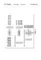
- FIG. 1 is an HVQ encoder which has a parallel error channel.
- FIG. 2 is the decoder for the arrangement of FIG. 1 .
- FIG. 3 is a one-channel arrangement for coding a pixel split into its most and least significant bits.
- FIG. 4 is a one-channel arrangement for decoding a pixel split into its most and least significant bits.
- FIG. 5 is a two-channel arrangement for coding a pixel split into its most and least significant bits.
- FIG. 6 is a decoder for the coder of FIG. 5 .
- FIG. 7 shows three processes of rotating or mirror imaging an image using HVQ compression.
- FIG. 8 shows a boundary between blocks of different sizes.
- FIG. 9 shows a boundary between blocks of the same size.
- the basic HVQ system can be improved by adding an error channel as shown in FIG. 1 .
- the grayscale byte map 16 is applied in the usual way to an HVQ decoder 10 , the output is losslessly compressed in an LZ encoder 11 , and the result is sent to the decoder, usually in the form of 8 to 10-bit words.
- the output of the HVQ encoder is sent to a decoder 12 in scanline format which produces a version of the original byte map which may be different from the original because of errors possibly introduced by the lossy encoder.
- the two byte maps are then subtracted 13 , pixel by pixel, to produce error terms which, if added to the output codeword, will produce the original byte map.
- This subtraction can also be done by using an exclusive OR, which is simpler and faster and does not require a sign bit.
- These error terms, each a signed quantity 8-bits wide or less, can then be compressed in an LZ encoder 15 combined in combiner 17 with the compressed code words to produce an output word and sent to the decoder. The larger the error term, the less will be the compression ratio.
- the error term can be limited to a few most significant bits, three for example, in quantizer 14 . Normally, the amount of error for a pixel will not be large enough to show up in the few MSB's, in which case there will be no error term at all.
- the quantized error decoder is shown in FIG. 2 .
- the output word from FIG. 1 is split into compressed code words and compressed quantized errors in receiver 25 .
- the compressed code words are LZ decoded in decoder 21 and HVQ decoded in decoder 22 to produce one term for the adder 23 .
- the compressed quantized errors are LZ decoded in decoder 24 and applied as the other term to the adder 23 , the output of which is output video.
- the adder 23 can either be an adder adding a sign bit and seven bits, or an exclusive OR if one was used to generate the error term in the encoder.
- FIG. 3 shows the arrangement when a single code word 31 is split into most and least significant parts, 32 , 33 , and where only the least significant bits are compressed.
- bits 0 through 4 are sent through lossy compressor 35 while bits 5 through 7 are not. Both are then compressed using lossless LZ compression ,combinined in combiner 37 and output to the decoder shown in FIG. 4 .
- the output word from FIG. 3 is split into least significant compressed code words and most significant compressed code words in receiver 25 . Then, both channels are LZ decompressed while only the LSB's are HVQ decoded. The two resultant parts are then exclusive ORed 44 together to be applied to the decoding look up table.
- FIG. 5 is a system where a single pixel is separated into a least significant segment and a most significant segment, and where a separate and different compression process is used for each segment, the least significant bits being more compressed.
- the original pixel is separated into its most significant bits 52 and least significant bits 53 .
- the result is that the most significant bits, being the most important, are less compressed while compression for the least significant bits has a better compression ratio.
- a programmable look-up table could be used to split the input pixel into any two segments other than the 3-5 split shown. The two compression results are combined in combiner 58 to produce an output word.
- FIG. 6 is the decoder for the encoder of FIG. 5 .
- the output word is split into its least and most significant parts, applied to LZ decoders 61 , 62 and HVQ 63 , 64 decoders. Then both are applied to an exclusive OR gate 65 to assemble the entire pixel.
- LZ decoders 61 , 62 and HVQ 63 , 64 decoders both are applied to an exclusive OR gate 65 to assemble the entire pixel.
- the decoder would use the same form of decoding. That is, more generally, the data words in a string can be divided into more and less significant bits to create two parallel strings, and then compressed using any two methods of compression where the greater compression is applied to less significant bits.
- HVQ compression is easily adapted to image rotation and mirror imaging as shown in FIG. 7 .
- the process is shown here using the example of an original image that is four pixels high and sixteen pixels wide, and must be rotated ninety degrees clockwise and mirror imaged.
- Step 1 is the usual compression process of reducing the eight 8-pixel segments to eight codewords Cw 1 to Cw 8 .
- Step 2 is the step of rearranging the codewords into the rotated and mirror imaged order.
- This hardware can be in the form of wiring where the second word in, for example Cw 2 , is connected to the third word out, as shown.
- Step 2 can have several sets of wiring, each set delivering a different rotation.
- decoding step 3 uses a look-up table to produce a pixel pattern for each segment that is properly oriented. Here again, several tables can be used to produce various orientations.
- Printing hints may be incorporated into the original data supplied by the user in the original page description language to indicate to the printer how the data may best be printed.
- a hint word may be two bits in length, and indicate one of four possibilities, that the following data is text, contone, graphics, etc. For example, if the printer is receiving data that originated as a computer generated graphic it may use a different halftone screen than it would if the original data was screened in from a photograph.
- Printing hints may be added to any HVQ channel as shown in FIG. 5 .
- the HVQ encoder 54 Assume that for each 4 pixel block entering into the HVQ encoder 54 there is produced one codeword 9 bits in length, contained in two 8-bit bytes, so that the first 8 bits are contained in the first byte and the last bit is contained in the second byte. Then the 2-bit hint is added. Now, each codeword plus hint is 11 bits, still contained in two bytes.
- the LZ encoder looks at a string of bytes, perhaps 256 bytes in length, and determines the location and size of the most recent identical pattern match. To the extent that the hint changes once or twice within that string, there will be a slightly decreased amount of compression in comparison to the amount that would have resulted with no hints.
- the losses of an HVQ compressor can be further minimized by choosing codewords and output data patterns that have the best chance of matching the actual input data patterns. For example, first consider text. If text pixels are being encoded in 4 by 2 pixel groups, and the four input pixels in one line are black, dark gray, light gray and white, and the input video was scanned-in text, the data most likely originally was a boundary between a black letter and a white space, so the output pixel pattern could be black, black, white, white. On the other hand, if the original input data was a scanned-in computer generated graphic, the four pixels are more likely to be a smooth decrease in density from black to white. The actual determination of the encoder codewords and patterns in the decoder look-up table are determined by statistical analysis. A representative group of text and graphic documents are passed through a test program and the best values are generated for each type.
- a complication arises when a boundary passes through an input block of pixels, in which case neither text nor graphic values can be used for the entire block.
- the solution is to supply a third set of codewords and patterns which are generated specifically for this boundary condition.
- a set of documents containing both text and graphics would be analyzed to produce one set of patterns, which would be used when a boundary, mixed, condition is determined to be within the block.
- the boundary condition is sensed by observing the printing hints.
- a rectangular scanned-in picture is typically located on a page of text by its x,y coordinates.
- the printing hints will indicate to the printer which codewords, look-up table entries and halftone screens to use. If the hint changes from picture to text within the block, for example, then the encoder knows that a boundary exists within the block.
- FIG. 8 is an example of a transition between text and contone. Since different block sizes can be used in HVQ encoders for different kinds of data, the block size for the text is shown here as 2 by 2 pixels to allow greater edge detail while the block size for contone is shown as being 4 by 2 to allow for greater compression.
- a boundary is within a 2 by 2 pixel block, that block is encoded and decoded using boundary values.
- any contone pixels to the right of the boundary such as pixel 81 are also treated as a boundary pixels if necessary so that all remaining pixels to the right of the boundary line will be within 4 by 2 pixel blocks.
- 2 by 2 pixel boundary blocks are used in pairs so that all remaining blocks will be 4 by 2.
Abstract
Description
Claims (3)
Priority Applications (4)
| Application Number | Priority Date | Filing Date | Title |
|---|---|---|---|
| US09/106,581 US6205252B1 (en) | 1998-06-29 | 1998-06-29 | Two channel HVQ (hierarchical vector quantization) compression |
| DE69905428T DE69905428T2 (en) | 1998-06-29 | 1999-06-15 | Unequal compression of MSBs and LSBs with hierarchical vector quantization |
| EP99304634A EP0969670B1 (en) | 1998-06-29 | 1999-06-15 | Unequal compression of MSBs and LSBs using Hierarchical Vector Quantization (HVQ) |
| JP11180854A JP2000049619A (en) | 1998-06-29 | 1999-06-25 | 2-channel hvq compression method |
Applications Claiming Priority (1)
| Application Number | Priority Date | Filing Date | Title |
|---|---|---|---|
| US09/106,581 US6205252B1 (en) | 1998-06-29 | 1998-06-29 | Two channel HVQ (hierarchical vector quantization) compression |
Publications (1)
| Publication Number | Publication Date |
|---|---|
| US6205252B1 true US6205252B1 (en) | 2001-03-20 |
Family
ID=22312196
Family Applications (1)
| Application Number | Title | Priority Date | Filing Date |
|---|---|---|---|
| US09/106,581 Expired - Lifetime US6205252B1 (en) | 1998-06-29 | 1998-06-29 | Two channel HVQ (hierarchical vector quantization) compression |
Country Status (4)
| Country | Link |
|---|---|
| US (1) | US6205252B1 (en) |
| EP (1) | EP0969670B1 (en) |
| JP (1) | JP2000049619A (en) |
| DE (1) | DE69905428T2 (en) |
Cited By (13)
| Publication number | Priority date | Publication date | Assignee | Title |
|---|---|---|---|---|
| US6529553B2 (en) | 1998-06-29 | 2003-03-04 | Xerox Corporation | HVQ compression for image boundaries |
| US20030123071A1 (en) * | 1998-12-18 | 2003-07-03 | Xerox Corporation | Time multiplexed image data decompression circuit |
| US6687771B2 (en) * | 2000-05-23 | 2004-02-03 | Arm Limited | Parallel processing of multiple data values within a data word |
| US20040263926A1 (en) * | 2003-06-30 | 2004-12-30 | Daewoo Electronics Corporation | Method and apparatus for compressing holographic data |
| US7155062B1 (en) * | 1999-11-17 | 2006-12-26 | Genicom Corp. | System and method for performing pattern matching image compression |
| US20070160299A1 (en) * | 2004-03-12 | 2007-07-12 | Canon Kabushiki Kaisha | Moving image coding apparatus, moving image decoding apparatus, control method therefor, computer program, and computer-readable storage medium |
| US20070217704A1 (en) * | 2006-02-08 | 2007-09-20 | Zhifang Zeng | Encoding method, encoding apparatus, decoding method, and decoding apparatus |
| US20080219571A1 (en) * | 2004-03-12 | 2008-09-11 | Masaki Suzuki | Moving Image Coding Apparatus, Moving Image Decoding Apparatus, Control Method Therefor, Computer Program, and Computer-Readable Storage Medium |
| US20090135904A1 (en) * | 2005-11-21 | 2009-05-28 | Edouard Francois | High-Dynamics Image Transmission System, Encoding and Decoding Units and Methods Therefor |
| US20090148208A1 (en) * | 2007-12-06 | 2009-06-11 | Kadant Web Systems, Inc. | Integrated doctor blade holders |
| US7965406B2 (en) | 2002-10-25 | 2011-06-21 | Xerox Corporation | Time multiplexed image data decompression circuit |
| US20170177227A1 (en) * | 2015-12-18 | 2017-06-22 | Imagination Technologies Limited | Lossy Data Compression |
| US9692692B1 (en) | 2015-09-29 | 2017-06-27 | Juniper Networks, Inc. | High-scale data center having LSP transport hierarchy |
Families Citing this family (4)
| Publication number | Priority date | Publication date | Assignee | Title |
|---|---|---|---|---|
| US6683980B1 (en) * | 2000-07-28 | 2004-01-27 | Microsoft Corporation | System and method for compressing data |
| US20230334028A1 (en) * | 2022-03-29 | 2023-10-19 | Imagination Technologies Limited | Data compression and decompression |
| GB2617112A (en) * | 2022-03-29 | 2023-10-04 | Imagination Tech Ltd | Data compression and decompression |
| GB2617111A (en) * | 2022-03-29 | 2023-10-04 | Imagination Tech Ltd | Data compression and decompression |
Citations (6)
| Publication number | Priority date | Publication date | Assignee | Title |
|---|---|---|---|---|
| US4745473A (en) * | 1986-03-24 | 1988-05-17 | Harris Corporation | Hybrid image compression system |
| US5140417A (en) * | 1989-06-20 | 1992-08-18 | Matsushita Electric Co., Ltd. | Fast packet transmission system of video data |
| US5253058A (en) * | 1992-04-01 | 1993-10-12 | Bell Communications Research, Inc. | Efficient coding scheme for multilevel video transmission |
| US5339164A (en) * | 1991-12-24 | 1994-08-16 | Massachusetts Institute Of Technology | Method and apparatus for encoding of data using both vector quantization and runlength encoding and using adaptive runlength encoding |
| US5689588A (en) * | 1996-01-03 | 1997-11-18 | Eastman Kodak Company | Method and apparatus for increasing compressibility of multibit image data with the LSB value determined in the thresholding operation based on pixel position |
| US5764802A (en) * | 1994-09-09 | 1998-06-09 | Intel Corporation | Encoding image signals using a blur image |
Family Cites Families (3)
| Publication number | Priority date | Publication date | Assignee | Title |
|---|---|---|---|---|
| US4679094A (en) * | 1986-10-14 | 1987-07-07 | The Associated Press | Method for compression and transmission of video information |
| US5272529A (en) * | 1992-03-20 | 1993-12-21 | Northwest Starscan Limited Partnership | Adaptive hierarchical subband vector quantization encoder |
| JP3202355B2 (en) * | 1992-10-27 | 2001-08-27 | キヤノン株式会社 | Hierarchical coding |
-
1998
- 1998-06-29 US US09/106,581 patent/US6205252B1/en not_active Expired - Lifetime
-
1999
- 1999-06-15 DE DE69905428T patent/DE69905428T2/en not_active Expired - Fee Related
- 1999-06-15 EP EP99304634A patent/EP0969670B1/en not_active Expired - Lifetime
- 1999-06-25 JP JP11180854A patent/JP2000049619A/en not_active Withdrawn
Patent Citations (6)
| Publication number | Priority date | Publication date | Assignee | Title |
|---|---|---|---|---|
| US4745473A (en) * | 1986-03-24 | 1988-05-17 | Harris Corporation | Hybrid image compression system |
| US5140417A (en) * | 1989-06-20 | 1992-08-18 | Matsushita Electric Co., Ltd. | Fast packet transmission system of video data |
| US5339164A (en) * | 1991-12-24 | 1994-08-16 | Massachusetts Institute Of Technology | Method and apparatus for encoding of data using both vector quantization and runlength encoding and using adaptive runlength encoding |
| US5253058A (en) * | 1992-04-01 | 1993-10-12 | Bell Communications Research, Inc. | Efficient coding scheme for multilevel video transmission |
| US5764802A (en) * | 1994-09-09 | 1998-06-09 | Intel Corporation | Encoding image signals using a blur image |
| US5689588A (en) * | 1996-01-03 | 1997-11-18 | Eastman Kodak Company | Method and apparatus for increasing compressibility of multibit image data with the LSB value determined in the thresholding operation based on pixel position |
Non-Patent Citations (2)
| Title |
|---|
| Lo et al., A contour coding and full-frame compression of discrete wavelet and cosine transforms, 10/1995, p. 9-12, vol. 2. Image Processing, 1995. Proceedings., International Conference on. * |
| Minami, CCITT H.261 Compatible Mixed Bit Rate Coding of Video for ATM Networks, 6/1992. p. 537-543, Communications, 1992, ICC '92, IEEE International Conference.* |
Cited By (22)
| Publication number | Priority date | Publication date | Assignee | Title |
|---|---|---|---|---|
| US6529553B2 (en) | 1998-06-29 | 2003-03-04 | Xerox Corporation | HVQ compression for image boundaries |
| US20030123071A1 (en) * | 1998-12-18 | 2003-07-03 | Xerox Corporation | Time multiplexed image data decompression circuit |
| US7349135B2 (en) * | 1998-12-18 | 2008-03-25 | Xerox Corporation | Time multiplexed image data decompression circuit |
| US7155062B1 (en) * | 1999-11-17 | 2006-12-26 | Genicom Corp. | System and method for performing pattern matching image compression |
| US6687771B2 (en) * | 2000-05-23 | 2004-02-03 | Arm Limited | Parallel processing of multiple data values within a data word |
| US7965406B2 (en) | 2002-10-25 | 2011-06-21 | Xerox Corporation | Time multiplexed image data decompression circuit |
| US20040263926A1 (en) * | 2003-06-30 | 2004-12-30 | Daewoo Electronics Corporation | Method and apparatus for compressing holographic data |
| US7391911B2 (en) * | 2003-06-30 | 2008-06-24 | Daewoo Electronics Corp. | Method and apparatus for compressing holographic data |
| US7822282B2 (en) * | 2004-03-12 | 2010-10-26 | Canon Kabushiki Kaisha | Moving image coding apparatus, moving image decoding apparatus, control method therefor, computer program, and computer-readable storage medium |
| US20070160299A1 (en) * | 2004-03-12 | 2007-07-12 | Canon Kabushiki Kaisha | Moving image coding apparatus, moving image decoding apparatus, control method therefor, computer program, and computer-readable storage medium |
| US20080219571A1 (en) * | 2004-03-12 | 2008-09-11 | Masaki Suzuki | Moving Image Coding Apparatus, Moving Image Decoding Apparatus, Control Method Therefor, Computer Program, and Computer-Readable Storage Medium |
| US7957604B2 (en) | 2004-03-12 | 2011-06-07 | Canon Kabushiki Kaisha | Moving image coding apparatus, moving image decoding apparatus, control method therefor, and computer-readable storage medium |
| US20090135904A1 (en) * | 2005-11-21 | 2009-05-28 | Edouard Francois | High-Dynamics Image Transmission System, Encoding and Decoding Units and Methods Therefor |
| US9083930B2 (en) | 2005-11-21 | 2015-07-14 | Thomson Licensing | High-dynamics image transmission system, encoding and decoding units and methods therefor |
| US20070217704A1 (en) * | 2006-02-08 | 2007-09-20 | Zhifang Zeng | Encoding method, encoding apparatus, decoding method, and decoding apparatus |
| US7983500B2 (en) * | 2006-02-08 | 2011-07-19 | Sony Corporation | Encoding method, encoding apparatus, decoding method, and decoding apparatus |
| US20090148208A1 (en) * | 2007-12-06 | 2009-06-11 | Kadant Web Systems, Inc. | Integrated doctor blade holders |
| US9692692B1 (en) | 2015-09-29 | 2017-06-27 | Juniper Networks, Inc. | High-scale data center having LSP transport hierarchy |
| US20170177227A1 (en) * | 2015-12-18 | 2017-06-22 | Imagination Technologies Limited | Lossy Data Compression |
| US10691360B2 (en) * | 2015-12-18 | 2020-06-23 | Imagination Technologies Limited | Lossy data compression |
| US11531479B2 (en) | 2015-12-18 | 2022-12-20 | Imagination Technologies Limited | Lossy data compression |
| US11836368B2 (en) | 2015-12-18 | 2023-12-05 | Imagination Technologies Limited | Lossy data compression |
Also Published As
| Publication number | Publication date |
|---|---|
| DE69905428T2 (en) | 2003-08-28 |
| EP0969670A1 (en) | 2000-01-05 |
| DE69905428D1 (en) | 2003-03-27 |
| JP2000049619A (en) | 2000-02-18 |
| EP0969670B1 (en) | 2003-02-19 |
Similar Documents
| Publication | Publication Date | Title |
|---|---|---|
| US6529553B2 (en) | HVQ compression for image boundaries | |
| US6205252B1 (en) | Two channel HVQ (hierarchical vector quantization) compression | |
| EP1285399B1 (en) | Enhanced compression of gray-level images | |
| US7873212B2 (en) | Compression of images for computer graphics | |
| US8107751B2 (en) | DPCM with adaptive range and PCM escape mode | |
| US7415154B2 (en) | Compression of palettized color images with variable length color codes | |
| EP2320380B1 (en) | Multi-mode image processing | |
| CN1266843C (en) | Coding method and system and decoding method and system | |
| US6078696A (en) | HVQ compression of data and printing hints | |
| EP0973339A2 (en) | Compression by splitting each word and applying lossy compression to least significant bits | |
| US6470052B1 (en) | HVQ compression combined with orthogonal rotation | |
| US6996269B2 (en) | Image encoding apparatus and image decoding apparatus | |
| EP0973340A2 (en) | HVQ compression with an error term | |
| US6347115B1 (en) | Method and system for predictive coding of images treated with the Roberts Method | |
| JPH05292328A (en) | Still picture coder | |
| JPH10108072A (en) | Image compression method and device therefor | |
| JPH07162689A (en) | Picture encoding device |
Legal Events
| Date | Code | Title | Description |
|---|---|---|---|
| AS | Assignment |
Owner name: XEROX CORPORATION, CONNECTICUT Free format text: ASSIGNMENT OF ASSIGNORS INTEREST;ASSIGNORS:NGUYEN, UOC H.;NGUYEN, KIEN T.;CLAPROTH, ABRAHAM E.;AND OTHERS;REEL/FRAME:009288/0874;SIGNING DATES FROM 19980623 TO 19980625 |
|
| STCF | Information on status: patent grant |
Free format text: PATENTED CASE |
|
| AS | Assignment |
Owner name: BANK ONE, NA, AS ADMINISTRATIVE AGENT, ILLINOIS Free format text: SECURITY INTEREST;ASSIGNOR:XEROX CORPORATION;REEL/FRAME:013153/0001 Effective date: 20020621 Owner name: BANK ONE, NA, AS ADMINISTRATIVE AGENT, ILLINOIS Free format text: SECURITY INTEREST;ASSIGNOR:XEROX CORPORATION;REEL/FRAME:013153/0001D Effective date: 20020621 |
|
| AS | Assignment |
Owner name: JPMORGAN CHASE BANK, AS COLLATERAL AGENT, TEXAS Free format text: SECURITY AGREEMENT;ASSIGNOR:XEROX CORPORATION;REEL/FRAME:015134/0476 Effective date: 20030625 Owner name: JPMORGAN CHASE BANK, AS COLLATERAL AGENT,TEXAS Free format text: SECURITY AGREEMENT;ASSIGNOR:XEROX CORPORATION;REEL/FRAME:015134/0476 Effective date: 20030625 |
|
| FPAY | Fee payment |
Year of fee payment: 4 |
|
| FPAY | Fee payment |
Year of fee payment: 8 |
|
| FPAY | Fee payment |
Year of fee payment: 12 |
|
| AS | Assignment |
Owner name: XEROX CORPORATION, CONNECTICUT Free format text: RELEASE BY SECURED PARTY;ASSIGNOR:JPMORGAN CHASE BANK, N.A. AS SUCCESSOR-IN-INTEREST ADMINISTRATIVE AGENT AND COLLATERAL AGENT TO JPMORGAN CHASE BANK;REEL/FRAME:066728/0193 Effective date: 20220822 |