US6209830B1 - Apparatus for camera mount on tripod platform - Google Patents
Apparatus for camera mount on tripod platform Download PDFInfo
- Publication number
- US6209830B1 US6209830B1 US09/444,434 US44443499A US6209830B1 US 6209830 B1 US6209830 B1 US 6209830B1 US 44443499 A US44443499 A US 44443499A US 6209830 B1 US6209830 B1 US 6209830B1
- Authority
- US
- United States
- Prior art keywords
- ball
- camera
- cradle
- diameter
- cradle cup
- Prior art date
- Legal status (The legal status is an assumption and is not a legal conclusion. Google has not performed a legal analysis and makes no representation as to the accuracy of the status listed.)
- Expired - Fee Related
Links
Images


Classifications
-
- F—MECHANICAL ENGINEERING; LIGHTING; HEATING; WEAPONS; BLASTING
- F16—ENGINEERING ELEMENTS AND UNITS; GENERAL MEASURES FOR PRODUCING AND MAINTAINING EFFECTIVE FUNCTIONING OF MACHINES OR INSTALLATIONS; THERMAL INSULATION IN GENERAL
- F16M—FRAMES, CASINGS OR BEDS OF ENGINES, MACHINES OR APPARATUS, NOT SPECIFIC TO ENGINES, MACHINES OR APPARATUS PROVIDED FOR ELSEWHERE; STANDS; SUPPORTS
- F16M11/00—Stands or trestles as supports for apparatus or articles placed thereon Stands for scientific apparatus such as gravitational force meters
- F16M11/02—Heads
- F16M11/04—Means for attachment of apparatus; Means allowing adjustment of the apparatus relatively to the stand
- F16M11/06—Means for attachment of apparatus; Means allowing adjustment of the apparatus relatively to the stand allowing pivoting
- F16M11/12—Means for attachment of apparatus; Means allowing adjustment of the apparatus relatively to the stand allowing pivoting in more than one direction
- F16M11/14—Means for attachment of apparatus; Means allowing adjustment of the apparatus relatively to the stand allowing pivoting in more than one direction with ball-joint
-
- F—MECHANICAL ENGINEERING; LIGHTING; HEATING; WEAPONS; BLASTING
- F16—ENGINEERING ELEMENTS AND UNITS; GENERAL MEASURES FOR PRODUCING AND MAINTAINING EFFECTIVE FUNCTIONING OF MACHINES OR INSTALLATIONS; THERMAL INSULATION IN GENERAL
- F16M—FRAMES, CASINGS OR BEDS OF ENGINES, MACHINES OR APPARATUS, NOT SPECIFIC TO ENGINES, MACHINES OR APPARATUS PROVIDED FOR ELSEWHERE; STANDS; SUPPORTS
- F16M13/00—Other supports for positioning apparatus or articles; Means for steadying hand-held apparatus or articles
Definitions
- Picture taking by a camera requires a steady, non-moving camera for clear well defined pictures, and in view of this, cameras are mounted on tripod platforms or tables, with camera angle adjustments attained by turning of gears, or unscrewing fasteners, to obtain the proper camera aiming angle.
- To disassemble the camera from this conventional mounting requires manipulation to unscrew the camera from the tripod table or platform.
- This present invention discloses apparatus and method for mounting a camera on a tripod platform by attaching to the camera a modified ball having a pear or partial oblate spheroid shape,and the assembly of the camera and modified ball with a conical segment part of the ball of pear shape set into a cradle cup attached to a tripod platform, to allow free rotational and tilt movement of the camera to aim at the desired picture subject.
- An object of this invention is to disclose apparatus for ball and cradle cup camera mount on a tripod platform by mounting a ball having a pear or partial oblate spheroid shape, onto the bottom of a camera, and the ball having a bottom cone segment, opposite the camera mount and attaching a cradle cup of cylindrical shape and having a diameter at the upper section of the cradle cup, greater than the ball diameter to the tripod platform and the assembly of the ball mounted on the camera set in the cradle cup with the ball extending into the cradle upper section, and the cone segment of the ball extending into the cradle cup lower section having a smaller diameter than the ball to allow rotation and tilting of the camera and camera mount ball assembly.
- Another object of this invention is to disclose a cradle cup mounted on a tripod platform and the cradle cup having an upper section diameter larger than the camera mount ball diameter, to allow entry of the ball shape, and the diameter of the cradle cup lower section is less than the camera mount ball diameter and the bottom cone section of the camera mount ball extends into the cradle cup lower section of cradle cup segment having a diameter less then the ball diameter.
- U.S. Pat. No. 855,149 for ATTACHMENT FOR TRIPOD CAMERA Disclosure is made of adjustable ball and socket mount for a camera mount on a tripod.
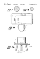
- FIG. 1 Plan view of camera mounting ball.
- FIG. 2 Cross section elevational view of camera mounting ball.
- FIG. 3 Plan view of ball cradle cup.
- FIG. 4 Elevational cross section view of ball cradle cup.
- FIG. 5 All set in cradle cup; elevational view.
- FIG. 6 Elevational view of ball tilted setting in cradle cup.
- FIG. 7 Plan view of bottom cone mount.
- FIG. 8 Plant view of bottom cone.
- FIG. 9 Camera and mount ball attached assembly
- FIG. 10 Clickle cup mounted on tripod platform.
- FIG. 11 Camera and mount ball sitting in cradle. cup mounted on tripod platform.
- FIG. 12 Camera and mount ball sitting in tilt position in cradle cup mounted on tripod platform.
- D′ Diameter of cradle cup lower section less than D.
- D′′ Diameter of cradle cup upper section greater than D.
- This invention is to disclose apparatus for providing stability to a camera for taking pictures for prevention of blurs, or fuzzy pictures.
- the apparatus includes as shown in FIGS. 1 , 2 , 5 , 6 , 9 , 11 , and 12 a camera mount ball 1 having a pear or oblate spheroid shape with a flat top 5 on the camera mount ball 1 and centered in the flat top 5 , of this camera mount ball 1 is a threaded insert 2 and a base segment bottom cone 3 , shown in FIGS. 7 and 8, as plan views of this bottom cone segment.
- FIG. 9 to show the camera mount ball 1 , and threaded insert 2 on camera mount ball 1 threaded into the camera 7 female threaded opening, which female threaded opening is standard in all cameras for mounting directly on a tripod platform.
- the assembly of the camera 7 , with the camera mount ball 1 attached to the camera 7 , as shown in FIG. 9 is placed in cradle cup 4 , of cylindrical shape (see FIGS. 5, 6 , 11 , 12 ) with the camera mount ball 1 extending into the cradle cup 4 .
- the cradle cup 4 is shown in FIGS. 3, 4 , 5 , 6 , 10 11 , and 12 , and is of cylindrical shape.
- FIG. 3 The plan view of the cradle cup 4 as shown in FIG. 3, and FIG. 4 is elevational cross section view.
- a threaded female insert 6 In the center of the bottom of the cradle cup 4 , is a threaded female insert 6 , for attachment by a threaded screw, of the cradle cup 4 to the platform 8 , of tripod 10 .
- ID′ is diameter of cradle cup 4 , lower section 12 less than D, and sets the limit of entry of camera mount ball 1 into the cradle cup 4 .
- ID′′ diameter of upper section 11 of cradle cup 4 is greater than diameter D of camera mount ball 1 .
- FIGS. 10, 11 and 12 show the tripod 10 , tripod platform 8 , and tripod legs 9 , and further FIGS. 9 and 10 are shown with the camera 7 and camera mount ball 1 assembly aligned with the cradle cup 4 , mounted on tripod platform 8 of tripod 10 and FIG. 11 shows the completed assembly of the camera 7 and camera mount ball 1 sitting in cradle cup 4 .
- the camera 7 in tilt position, with camera mount ball 1 attached and the camera mount ball sitting in cradle cup 4 , allows for free rotational movement of the camera 7 and camera mount ball 1 assembly and further the camera-ball assembly can be tilted to aim the camera either up or down.
- the tilt is limited by bottom cone 3 segment of the camera mount ball 1 hitting the inner wall of the cradle cup 4 as shown in FIG. 12, and further this insures the camera 7 camera ball mount 1 assembly against falling out of the cradle cup 4 when in any tilt position.
- the above described apparatus simplifies the rapid removal of the camera from the cradle cup 4 by simply lifting the camera 7 camera mount ball 1 assembly from the cradle, cup 4 without unscrewing any mounting screws or control levers.
- this invention discloses apparatus of a camera mount ball 1 , attached to camera 7 by a threaded screw 2 extending into female thread in the camera bottom and a cradle cup 4 rigidly mounted on a tripod platform 8 and the camera mount ball 1 with a bottom cone section 3 opposite the camera mount on the ball and the camera 7 with camera mount ball 1 attached placed in the cradle cup 4 and the ball extending into the cradle cup 4 having a top diameter D′′ section at the top section 11 of the cradle cup 4 greater than the ball diameter D and the bottom cone section 3 of the ball extending into the cradle cup 4 lower section 12 having a smaller diameter D′ than the ball diameter D to allow rotation and tilting of the camera and camera mount ball assembly.
- the cradle cup 4 mounted on a tripod platform 8 and the cradle cup 4 has a top section 11 diameter D′′ larger than the camera mount ball 1 diameter D, to allow entry of the camera mount ball 1 into the cradle cup 4 and the cradle cup 4 has a bottom section 12 diameter D′ smaller than the camera mount ball 1 diameter D and the bottom cone section 3 of the camera mount ball 1 extends into the cradle cup 4 lower section 12 having a diameter D′ less then the camera mount ball 1 diameter D.
- the static friction between the ball shape and the cradle cup should be sufficient to hold the camera 7 in any set position, yet having low sliding friction to be easily moved to any other desired position.
- This described apparatus for camera mount on a tripod platform allows for rapid mounting and de-mounting of the camera on a tripod platform.
- the components of the camera mount ball 1 and cradle cup 4 may be formed of thermoplastic such as nylon, polyester, polyethylene, or polypropylene, or thermoset plastic material such as phenolic, melamine, melamine/phenolic polyester, polyurethane or urea, or other types of plastic or from other machined or formed material.
- thermoplastic such as nylon, polyester, polyethylene, or polypropylene
- thermoset plastic material such as phenolic, melamine, melamine/phenolic polyester, polyurethane or urea, or other types of plastic or from other machined or formed material.
Abstract
Description
Claims (2)
Priority Applications (2)
| Application Number | Priority Date | Filing Date | Title |
|---|---|---|---|
| US09/444,434 US6209830B1 (en) | 1999-11-22 | 1999-11-22 | Apparatus for camera mount on tripod platform |
| US09/747,267 US6439518B2 (en) | 1999-11-22 | 2000-12-26 | Apparatus for camera mount on tripod platform |
Applications Claiming Priority (1)
| Application Number | Priority Date | Filing Date | Title |
|---|---|---|---|
| US09/444,434 US6209830B1 (en) | 1999-11-22 | 1999-11-22 | Apparatus for camera mount on tripod platform |
Related Child Applications (1)
| Application Number | Title | Priority Date | Filing Date |
|---|---|---|---|
| US09/747,267 Continuation-In-Part US6439518B2 (en) | 1999-11-22 | 2000-12-26 | Apparatus for camera mount on tripod platform |
Publications (1)
| Publication Number | Publication Date |
|---|---|
| US6209830B1 true US6209830B1 (en) | 2001-04-03 |
Family
ID=23764867
Family Applications (1)
| Application Number | Title | Priority Date | Filing Date |
|---|---|---|---|
| US09/444,434 Expired - Fee Related US6209830B1 (en) | 1999-11-22 | 1999-11-22 | Apparatus for camera mount on tripod platform |
Country Status (1)
| Country | Link |
|---|---|
| US (1) | US6209830B1 (en) |
Cited By (19)
| Publication number | Priority date | Publication date | Assignee | Title |
|---|---|---|---|---|
| US6437826B1 (en) * | 1998-07-06 | 2002-08-20 | Conexant Systems, Inc. | Digital video teleconferencing camera system having a base |
| US6439518B2 (en) * | 1999-11-22 | 2002-08-27 | Plastics Engineering Co. | Apparatus for camera mount on tripod platform |
| US20050122424A1 (en) * | 2003-12-09 | 2005-06-09 | Overstreet Frank R. | Positioning accessory for camera-equipped wireless terminals |
| US7163181B2 (en) | 2002-12-18 | 2007-01-16 | Omps Justin T | Magnetic mounting assembly |
| US20070114346A1 (en) * | 2002-12-18 | 2007-05-24 | Omps Justin T | Magnetic mounting assembly |
| US20080247746A1 (en) * | 2007-04-05 | 2008-10-09 | David Law | Tripod Mounting, Stand, or Support Attachment, Accessory, or Mechanism for Cameras and Similar Devices or Objects |
| US20080245945A1 (en) * | 2007-04-05 | 2008-10-09 | David Law | Modified tripod and "multi-pod" for cameras and other equipment |
| US20090026331A1 (en) * | 2007-07-26 | 2009-01-29 | Hung Hi Law | Portable Supporting Apparatus |
| US20120305733A1 (en) * | 2011-05-31 | 2012-12-06 | Blackglass, Llc | Multi-positional Mount For Personal Electronic Devices With A Magnetic Interface |
| CN103912770A (en) * | 2014-03-14 | 2014-07-09 | 泰州市兴东煤矿机械制造有限公司 | Support special for camera |
| US20150198865A1 (en) * | 2014-01-13 | 2015-07-16 | Beseye Cloud Security Co., Ltd. | Rotatable camera device |
| USD734746S1 (en) | 2011-05-31 | 2015-07-21 | Nite Ize, Inc. | Phone kit |
| US9097379B1 (en) * | 2010-10-25 | 2015-08-04 | Gomite, LLC | Articulating support for electronic devices |
| US10054260B2 (en) * | 2016-02-03 | 2018-08-21 | Modernsolid Industrial Co., Ltd. | Rotation-adjustable hanging device |
| US10520127B2 (en) | 2017-06-20 | 2019-12-31 | Microsoft Technology Licensing, Llc | Mounting system capable of receiving threaded and threadless posts |
| US20200080685A1 (en) * | 2015-06-03 | 2020-03-12 | Zipwall, Llc | Mounting unit for partition mount |
| WO2020102237A1 (en) * | 2018-11-13 | 2020-05-22 | Opkix, Inc. | Wearable mounts for portable camera |
| EP3755936A4 (en) * | 2018-07-26 | 2021-10-06 | Hewlett-Packard Development Company, L.P. | Magnetic multiple axis mounts |
| US11558538B2 (en) | 2016-03-18 | 2023-01-17 | Opkix, Inc. | Portable camera system |
Citations (5)
| Publication number | Priority date | Publication date | Assignee | Title |
|---|---|---|---|---|
| US318480A (en) * | 1885-05-19 | Island | ||
| US1764721A (en) * | 1926-11-13 | 1930-06-17 | Arthur C Hayden | Support for panoramic cameras |
| US1780383A (en) * | 1928-06-13 | 1930-11-04 | Irving I Green | Camera tripod |
| US2672313A (en) * | 1951-01-12 | 1954-03-16 | Clare J Poole | Hydraulic camera tripod head |
| US4016583A (en) * | 1975-06-24 | 1977-04-05 | Yeates Calvin B | Camera steadying device |
-
1999
- 1999-11-22 US US09/444,434 patent/US6209830B1/en not_active Expired - Fee Related
Patent Citations (5)
| Publication number | Priority date | Publication date | Assignee | Title |
|---|---|---|---|---|
| US318480A (en) * | 1885-05-19 | Island | ||
| US1764721A (en) * | 1926-11-13 | 1930-06-17 | Arthur C Hayden | Support for panoramic cameras |
| US1780383A (en) * | 1928-06-13 | 1930-11-04 | Irving I Green | Camera tripod |
| US2672313A (en) * | 1951-01-12 | 1954-03-16 | Clare J Poole | Hydraulic camera tripod head |
| US4016583A (en) * | 1975-06-24 | 1977-04-05 | Yeates Calvin B | Camera steadying device |
Cited By (32)
| Publication number | Priority date | Publication date | Assignee | Title |
|---|---|---|---|---|
| US6437826B1 (en) * | 1998-07-06 | 2002-08-20 | Conexant Systems, Inc. | Digital video teleconferencing camera system having a base |
| US6439518B2 (en) * | 1999-11-22 | 2002-08-27 | Plastics Engineering Co. | Apparatus for camera mount on tripod platform |
| US7163181B2 (en) | 2002-12-18 | 2007-01-16 | Omps Justin T | Magnetic mounting assembly |
| US20070114346A1 (en) * | 2002-12-18 | 2007-05-24 | Omps Justin T | Magnetic mounting assembly |
| US7621492B2 (en) | 2002-12-18 | 2009-11-24 | Omps Justin T | Magnetic mounting assembly |
| US7551225B2 (en) * | 2003-12-09 | 2009-06-23 | Sony Ericsson Mobile Communications Ab | Positioning accessory for camera-equipped wireless terminals |
| US20050122424A1 (en) * | 2003-12-09 | 2005-06-09 | Overstreet Frank R. | Positioning accessory for camera-equipped wireless terminals |
| US20080245945A1 (en) * | 2007-04-05 | 2008-10-09 | David Law | Modified tripod and "multi-pod" for cameras and other equipment |
| US20080247746A1 (en) * | 2007-04-05 | 2008-10-09 | David Law | Tripod Mounting, Stand, or Support Attachment, Accessory, or Mechanism for Cameras and Similar Devices or Objects |
| US7780126B2 (en) | 2007-04-05 | 2010-08-24 | Daymen Photo Marketing Lp | Modified tripod and “multi-pod” for cameras and other equipment |
| US20090026331A1 (en) * | 2007-07-26 | 2009-01-29 | Hung Hi Law | Portable Supporting Apparatus |
| US7621491B2 (en) * | 2007-07-26 | 2009-11-24 | Hung Hi Law | Portable supporting apparatus |
| US9097379B1 (en) * | 2010-10-25 | 2015-08-04 | Gomite, LLC | Articulating support for electronic devices |
| US20150048237A1 (en) * | 2011-05-31 | 2015-02-19 | Nite Ize, Inc. | Multi-positional mount for personal electronic devices with a magnetic interface |
| US8870146B2 (en) | 2011-05-31 | 2014-10-28 | Nite Ize, Inc. | Multi-positional mount for personal electronic devices with a magnetic interface |
| US8602376B2 (en) * | 2011-05-31 | 2013-12-10 | Nite Ize, Inc. | Multi-positional mount for personal electronic devices with a magnetic interface |
| USD734746S1 (en) | 2011-05-31 | 2015-07-21 | Nite Ize, Inc. | Phone kit |
| US20120305733A1 (en) * | 2011-05-31 | 2012-12-06 | Blackglass, Llc | Multi-positional Mount For Personal Electronic Devices With A Magnetic Interface |
| US9765921B2 (en) * | 2011-05-31 | 2017-09-19 | Nite Ize, Inc. | Multi-positional mount for personal electronic devices with a magnetic interface |
| US20170356591A1 (en) * | 2011-05-31 | 2017-12-14 | Nite Ize, Inc. | Multi-positional mount for personal electronic devices with a magnetic interface |
| US10066779B2 (en) * | 2011-05-31 | 2018-09-04 | Nite Ize, Inc. | Multi-positional mount for personal electronic devices with a magnetic interface |
| US20150198865A1 (en) * | 2014-01-13 | 2015-07-16 | Beseye Cloud Security Co., Ltd. | Rotatable camera device |
| CN103912770A (en) * | 2014-03-14 | 2014-07-09 | 泰州市兴东煤矿机械制造有限公司 | Support special for camera |
| US20200080685A1 (en) * | 2015-06-03 | 2020-03-12 | Zipwall, Llc | Mounting unit for partition mount |
| US10961730B2 (en) * | 2015-06-03 | 2021-03-30 | Zipwall, Llc | Mounting unit for partition mount |
| US10054260B2 (en) * | 2016-02-03 | 2018-08-21 | Modernsolid Industrial Co., Ltd. | Rotation-adjustable hanging device |
| US11558538B2 (en) | 2016-03-18 | 2023-01-17 | Opkix, Inc. | Portable camera system |
| US10520127B2 (en) | 2017-06-20 | 2019-12-31 | Microsoft Technology Licensing, Llc | Mounting system capable of receiving threaded and threadless posts |
| EP3755936A4 (en) * | 2018-07-26 | 2021-10-06 | Hewlett-Packard Development Company, L.P. | Magnetic multiple axis mounts |
| US11448246B2 (en) * | 2018-07-26 | 2022-09-20 | Hewlett-Packard Development Company, L.P. | Magnetic multiple axis mounts |
| WO2020102237A1 (en) * | 2018-11-13 | 2020-05-22 | Opkix, Inc. | Wearable mounts for portable camera |
| US11300857B2 (en) | 2018-11-13 | 2022-04-12 | Opkix, Inc. | Wearable mounts for portable camera |
Similar Documents
| Publication | Publication Date | Title |
|---|---|---|
| US6209830B1 (en) | Apparatus for camera mount on tripod platform | |
| US6439518B2 (en) | Apparatus for camera mount on tripod platform | |
| US11221544B1 (en) | Portable camera support device for elevated photography and/or videography | |
| US4516751A (en) | Wall bracket system | |
| US4974802A (en) | Adjustable swivel | |
| US5029795A (en) | Camera support stand | |
| US3568963A (en) | Mounting | |
| US20070152116A1 (en) | Ball head | |
| US20040079858A1 (en) | Support device for liquid crystal flat screen | |
| US5398444A (en) | Adjustable tree stand | |
| US20040079849A1 (en) | Support device for a liquid crystal flat screen | |
| US20020154789A1 (en) | Adjustable microphone stand | |
| US5556091A (en) | Baseball holder for baseball batting practice | |
| EP1939518B1 (en) | Tripod assembly | |
| EP1612599A1 (en) | Panorama photograping support device | |
| EP0461661A2 (en) | Tiltable turntable for display monitor | |
| US11480290B2 (en) | Travel tripod | |
| US6731340B1 (en) | Surface-mount video camera adapted to be mounted on and used with a personal computer | |
| US5888014A (en) | Extensible lockable apparatus | |
| US4411395A (en) | Downrigger swivel base | |
| AU757766B2 (en) | Camera leveling head | |
| US20040096207A1 (en) | Camera support | |
| US9618830B1 (en) | Photography workstation | |
| CN108843911B (en) | Adjustable base | |
| US5517354A (en) | Adjustable microscope base |
Legal Events
| Date | Code | Title | Description |
|---|---|---|---|
| AS | Assignment |
Owner name: PLASTICS ENGINEERING CO., WISCONSIN Free format text: ASSIGNMENT OF ASSIGNORS INTEREST;ASSIGNOR:BROTZ, RALPH T.;REEL/FRAME:010460/0631 Effective date: 19991203 |
|
| FEPP | Fee payment procedure |
Free format text: PAYOR NUMBER ASSIGNED (ORIGINAL EVENT CODE: ASPN); ENTITY STATUS OF PATENT OWNER: SMALL ENTITY Free format text: PAT HOLDER CLAIMS SMALL ENTITY STATUS, ENTITY STATUS SET TO SMALL (ORIGINAL EVENT CODE: LTOS); ENTITY STATUS OF PATENT OWNER: SMALL ENTITY |
|
| FPAY | Fee payment |
Year of fee payment: 4 |
|
| FPAY | Fee payment |
Year of fee payment: 8 |
|
| REMI | Maintenance fee reminder mailed | ||
| LAPS | Lapse for failure to pay maintenance fees | ||
| LAPS | Lapse for failure to pay maintenance fees |
Free format text: PATENT EXPIRED FOR FAILURE TO PAY MAINTENANCE FEES (ORIGINAL EVENT CODE: EXP.); ENTITY STATUS OF PATENT OWNER: SMALL ENTITY |
|
| STCH | Information on status: patent discontinuation |
Free format text: PATENT EXPIRED DUE TO NONPAYMENT OF MAINTENANCE FEES UNDER 37 CFR 1.362 |
|
| FP | Lapsed due to failure to pay maintenance fee |
Effective date: 20130403 |