US6213819B1 - Detachable fan rack for computer - Google Patents
Detachable fan rack for computer Download PDFInfo
- Publication number
- US6213819B1 US6213819B1 US09/589,762 US58976200A US6213819B1 US 6213819 B1 US6213819 B1 US 6213819B1 US 58976200 A US58976200 A US 58976200A US 6213819 B1 US6213819 B1 US 6213819B1
- Authority
- US
- United States
- Prior art keywords
- mounting frame
- plug
- fan
- locking plate
- holder
- Prior art date
- Legal status (The legal status is an assumption and is not a legal conclusion. Google has not performed a legal analysis and makes no representation as to the accuracy of the status listed.)
- Expired - Fee Related
Links
Images


Classifications
-
- G—PHYSICS
- G06—COMPUTING; CALCULATING OR COUNTING
- G06F—ELECTRIC DIGITAL DATA PROCESSING
- G06F1/00—Details not covered by groups G06F3/00 - G06F13/00 and G06F21/00
- G06F1/16—Constructional details or arrangements
- G06F1/20—Cooling means
-
- F—MECHANICAL ENGINEERING; LIGHTING; HEATING; WEAPONS; BLASTING
- F04—POSITIVE - DISPLACEMENT MACHINES FOR LIQUIDS; PUMPS FOR LIQUIDS OR ELASTIC FLUIDS
- F04D—NON-POSITIVE-DISPLACEMENT PUMPS
- F04D29/00—Details, component parts, or accessories
- F04D29/60—Mounting; Assembling; Disassembling
- F04D29/601—Mounting; Assembling; Disassembling specially adapted for elastic fluid pumps
Definitions
- the present invention relates to a fan rack for computer, and more particularly to a detachable fan rack that enables the user to replace the fan without cutting power supply from the computer.
- a computer has a fan rack holding at least one fan for dissipation of heat.
- the power circuit of each fan is welded to the power circuit of the computer to obtain the necessary working voltage from the computer.
- the power circuit of the computer In case one fan fails, the power circuit of the computer must be turned off so that the failed fan can be disconnected from the fan rack for a repair work or replacement without causing damage to the internal circuit of the computer.
- a big loss may occur when cutting off power supply from a computer been used in an industrial or financial place to run a control or to provide a service.
- the fan rack comprises a mounting frame, and a fan holder.
- the mounting frame comprises a receiving opening, a plurality of hook holes, a plug hole, a locating notch and a plug hole spaced around the center opening.
- the fan holder is mounted on the mounting frame to hold a fan in the center opening on the mounting frame, comprising a holder base and a locking plate.
- the holder base comprises bottom mounting legs respectively hooked in the hook holes on the mounting frame, a plug mount holding an electric plug, a clamping plate clamped on the retaining portion at the mounting frame, a hook at one side, and a positioning member positioned in the locating notch on the mounting frame.
- the locking plate is coupled to the holder base at one side and turned between a first position where the locking plate is engaged into the plug hole on the mounting frame and hooked up with the hook at the holder base to lock the fan holder, and a second position where the locking plate is disengaged from the plug hole and the hook for enabling the fan holder to be disconnected from the mounting frame.
- FIG. 1 is an exploded view of a fan holder for a detachable fan rack according to the present invention.
- FIG. 2 is a perspective view of the present invention, showing the fan holders installed in the mounting frame.
- FIG. 3 is an exploded view of FIG. 2 .
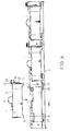
- FIG. 4 is a side plain view of FIG. 3 .
- FIG. 5 is a side plain view of a part of the detachable fan rack according to the present invention showing the locking plate unlocked.
- FIG. 6 is similar to FIG. 5 but showing the locking plate locked.
- FIG. 7 is a plain view of a part of the present invention, showing the fan holder disconnected from the mounting frame.
- a detachable fan rack in accordance with the present invention comprises a plurality of fan holders 1 holding a respective fan, and a mounting frame 2 .
- Each fan holder 1 comprises a holder base 11 , a locking plate 12 , a plug mount 13 , and a springy clamping plate 14 .
- the holder base 11 comprises four L-shaped mounting legs 111 disposed in four comers thereof, a positioning member 112 vertically downwardly suspended at one side, a plug plate 113 vertically downwardly disposed at one side opposite to the positioning member 112 , a raised portion 114 and a hook 116 spaced from the plug plate 113 at two opposite lateral sides, and a stop plate 115 disposed adjacent to the raised portion 114 .
- the plug plate 113 has a downwardly extended coupling notch 1131 .
- the locking plate 12 comprises a base 122 and a finger strip 121 extended from one side of the base 122 .
- the base 122 comprises a bolt 1221 coupled to the coupling notch 1121 on the plug plate 113 , a guide groove 1222 coupled to the raised portion 114 , and a lock hole 1223 .
- the locking plate 12 is coupled to the plug plate 113 .
- the plug mount 13 is fastened to one side of the holder base 11 opposite to the locking plate 12 to hold an electric plug, comprising a wire clip 131 for securing lead out wires that extend out of a wire hole 117 on the holder base 11 and connected to a circuit board for electric plug being secured to the plug mount 13 by the springy clamping plate 14 .
- each fan holder positioning structure comprises a receiving opening 22 , which receives one fan holder 1 , a locating notch 221 at the periphery of the receiving opening 22 for the positioning of the positioning member 112 of the corresponding fan holder 1 , a plug hole 23 for receiving the base 122 of the locking plate 12 , a retaining portion 24 for engagement with the clamping plate 14 of the corresponding fan holder 1 , and a plurality of positioning notches 21 spaced around the receiving opening 22 and defining a respective hook hole 211 for engagement with the L-shaped mounting legs 111 of the corresponding fan holder 1 .
- the locking plate 12 is turned between the unlocking position where the base 122 of the locking plate 12 is stopped at the stop plate 115 , and a locking position where the base 122 of the locking plate 12 is engaged into the plug hole 23 of the corresponding fan holder positioning structure and the lock hole 1223 is forced into engagement with the hook 116 at the holder base 11 of the corresponding fan holder 1 .
- the locking plate 12 when replacing the fan in one fan holder 1 , the locking plate 12 is turned from the locking position to the unlocking position to disengage the lock hole 1223 from the hook 116 m and then the clamping plate 14 is pushed to disengage the tongue 141 from the retaining portion 24 , enabling the holder base 11 to be disconnected from the mounting frame 2 for replacement of the fan.
Abstract
A detachable fan rack includes a mounting frame, and a fan holder, the mounting frame having a receiving opening, a plurality of hook holes, a plug hole, a locating notch and a plug hole spaced around the center opening, the fan holder being mounted on the mounting frame to hold a fan in the center opening on the mounting frame, the fan holder including a holder base and a locking plate, the holder base having bottom mounting legs respectively hooked in the hook holes on the mounting frame, a plug mount holding an electric plug, a clamping plate clamped on the retaining portion at the mounting frame, a hook at one side, and a positioning member positioned in the locating notch on the mounting frame, the locking plate being coupled to the holder base at one side and turned between a first position where the locking plate is engaged into the plug hole on said mounting frame and hooked up with the hook at the holder base to lock the fan holder, and a second position where the locking plate is disengaged from the plug hole and the hook for enabling the fan holder to be disconnected from the mounting frame.
Description
The present invention relates to a fan rack for computer, and more particularly to a detachable fan rack that enables the user to replace the fan without cutting power supply from the computer.
A computer has a fan rack holding at least one fan for dissipation of heat. The power circuit of each fan is welded to the power circuit of the computer to obtain the necessary working voltage from the computer. In case one fan fails, the power circuit of the computer must be turned off so that the failed fan can be disconnected from the fan rack for a repair work or replacement without causing damage to the internal circuit of the computer. However, a big loss may occur when cutting off power supply from a computer been used in an industrial or financial place to run a control or to provide a service.
It is the main object of the present invention to provide a fan rack for computer, which enables the user to replace the fan (or fans) without cutting off power supply from the computer in which the fan rack is installed. According to the present invention, the fan rack comprises a mounting frame, and a fan holder. The mounting frame comprises a receiving opening, a plurality of hook holes, a plug hole, a locating notch and a plug hole spaced around the center opening. The fan holder is mounted on the mounting frame to hold a fan in the center opening on the mounting frame, comprising a holder base and a locking plate. The holder base comprises bottom mounting legs respectively hooked in the hook holes on the mounting frame, a plug mount holding an electric plug, a clamping plate clamped on the retaining portion at the mounting frame, a hook at one side, and a positioning member positioned in the locating notch on the mounting frame. The locking plate is coupled to the holder base at one side and turned between a first position where the locking plate is engaged into the plug hole on the mounting frame and hooked up with the hook at the holder base to lock the fan holder, and a second position where the locking plate is disengaged from the plug hole and the hook for enabling the fan holder to be disconnected from the mounting frame.
FIG. 1 is an exploded view of a fan holder for a detachable fan rack according to the present invention.
FIG. 2 is a perspective view of the present invention, showing the fan holders installed in the mounting frame.
FIG. 3 is an exploded view of FIG. 2.
FIG. 4 is a side plain view of FIG. 3.
FIG. 5 is a side plain view of a part of the detachable fan rack according to the present invention showing the locking plate unlocked.
FIG. 6 is similar to FIG. 5 but showing the locking plate locked.
FIG. 7 is a plain view of a part of the present invention, showing the fan holder disconnected from the mounting frame.
Referring to FIGS. From 1 through 3, a detachable fan rack in accordance with the present invention comprises a plurality of fan holders 1 holding a respective fan, and a mounting frame 2. Each fan holder 1 comprises a holder base 11, a locking plate 12, a plug mount 13, and a springy clamping plate 14. The holder base 11 comprises four L-shaped mounting legs 111 disposed in four comers thereof, a positioning member 112 vertically downwardly suspended at one side, a plug plate 113 vertically downwardly disposed at one side opposite to the positioning member 112, a raised portion 114 and a hook 116 spaced from the plug plate 113 at two opposite lateral sides, and a stop plate 115 disposed adjacent to the raised portion 114. The plug plate 113 has a downwardly extended coupling notch 1131. The locking plate 12 comprises a base 122 and a finger strip 121 extended from one side of the base 122. The base 122 comprises a bolt 1221 coupled to the coupling notch 1121 on the plug plate 113, a guide groove 1222 coupled to the raised portion 114, and a lock hole 1223. The locking plate 12 is coupled to the plug plate 113. The plug mount 13 is fastened to one side of the holder base 11 opposite to the locking plate 12 to hold an electric plug, comprising a wire clip 131 for securing lead out wires that extend out of a wire hole 117 on the holder base 11 and connected to a circuit board for electric plug being secured to the plug mount 13 by the springy clamping plate 14.
Referring to FIGS. 3 and 4, the mounting frame 2 comprising a plurality of fan holder positioning structures for the positioning of the fan holders 1. Each fan holder positioning structure comprises a receiving opening 22, which receives one fan holder 1, a locating notch 221 at the periphery of the receiving opening 22 for the positioning of the positioning member 112 of the corresponding fan holder 1, a plug hole 23 for receiving the base 122 of the locking plate 12, a retaining portion 24 for engagement with the clamping plate 14 of the corresponding fan holder 1, and a plurality of positioning notches 21 spaced around the receiving opening 22 and defining a respective hook hole 211 for engagement with the L-shaped mounting legs 111 of the corresponding fan holder 1.
Referring to FIGS. 3 and 4 again, when mounting one fan holder 1 in the L-shaped mounting legs 111 are respectively inserted into the positioning notches 21 and engaged into the hook hole 211 in each positioning notch 21, and at the same time the positioning member 112 of the fan holder 1 is positioned in the locating notch 221, and a tongue 141 of the clamping plate 14 is forced into engagement with the retaining portion 24.
Referring to FIGS. 5 and 6, after mounting of one fan holder 1 in the mounting frame 2, the locking plate 12 is turned between the unlocking position where the base 122 of the locking plate 12 is stopped at the stop plate 115, and a locking position where the base 122 of the locking plate 12 is engaged into the plug hole 23 of the corresponding fan holder positioning structure and the lock hole 1223 is forced into engagement with the hook 116 at the holder base 11 of the corresponding fan holder 1.
Referring to FIG. 7, when replacing the fan in one fan holder 1, the locking plate 12 is turned from the locking position to the unlocking position to disengage the lock hole 1223 from the hook 116 m and then the clamping plate 14 is pushed to disengage the tongue 141 from the retaining portion 24, enabling the holder base 11 to be disconnected from the mounting frame 2 for replacement of the fan.
While only one embodiment of the present invention has been shown and described, it will be understood that various modifications and changes could be made thereunto without departing from the spirit and scope of the invention disclosed.
Claims (1)
1. A detachable fan rack comprising:
a mounting frame, said mounting frame comprising a receiving opening, a locating notch at the periphery of said receiving opening, a plug hole disposed adjacent to said receiving hole at one side opposite to said locating notch, a retaining portion, and a plurality of positioning notches spaced around said receiving opening, and a plurality of hook holes respectively defined in said positioning notches; and
a fan holder detachably mounted on said mounting frame to hold an electric fan in said receiving opening, said fan holder comprising a holder base, a plug mount fixedly provided at one side of said holder base to hold an electric plug, a clamping plate installed in said plug mount, and a locking plate coupled to said holder base for locking said holder base after installation of said holder base in said mounting frame, said holder base comprising a plurality of mounting legs respectively inserted into said positioning notches and engaged into said hook holes, positioning member vertically downwardly suspended at one side and coupled to the locating notch on said mounting frame, a plug plate vertically downwardly disposed at one side opposite to said positioning member and positioned in the locating notch on said mounting frame, a raised portion and a hook spaced from said plug plate at two opposite lateral sides, and a stop plate disposed adjacent to said raised portion, said plug plate having a downwardly extended coupling notch, said locking plate comprising a base, and a finger strip formed integral with one side of the base of said locking plate, the base of said locking plate comprising a bolt coupled to the coupling notch on said plug plate for enabling said locking plate to be turned between a first position where the base of said locking plate is engaged into the plug hole on said mounting frame and a second position where the base of said locking plate is disengaged from the plug hole on said mounting frame and stopped at said locating plate, a guide groove coupled to said raised portion to guide turning of said locking plate between said first position and said second position, and a lock hole for engagement with said hook when said locking plate is moved to said first position, said springy clamping plate having a tongue forced into engagement with the retaining portion at said mounting frame.
Priority Applications (2)
| Application Number | Priority Date | Filing Date | Title |
|---|---|---|---|
| DE20006849U DE20006849U1 (en) | 2000-04-13 | 2000-04-13 | Exchangeable fan without cut-off |
| US09/589,762 US6213819B1 (en) | 2000-04-13 | 2000-06-09 | Detachable fan rack for computer |
Applications Claiming Priority (2)
| Application Number | Priority Date | Filing Date | Title |
|---|---|---|---|
| DE20006849U DE20006849U1 (en) | 2000-04-13 | 2000-04-13 | Exchangeable fan without cut-off |
| US09/589,762 US6213819B1 (en) | 2000-04-13 | 2000-06-09 | Detachable fan rack for computer |
Publications (1)
| Publication Number | Publication Date |
|---|---|
| US6213819B1 true US6213819B1 (en) | 2001-04-10 |
Family
ID=26056206
Family Applications (1)
| Application Number | Title | Priority Date | Filing Date |
|---|---|---|---|
| US09/589,762 Expired - Fee Related US6213819B1 (en) | 2000-04-13 | 2000-06-09 | Detachable fan rack for computer |
Country Status (2)
| Country | Link |
|---|---|
| US (1) | US6213819B1 (en) |
| DE (1) | DE20006849U1 (en) |
Cited By (46)
| Publication number | Priority date | Publication date | Assignee | Title |
|---|---|---|---|---|
| US6396689B1 (en) * | 2000-08-02 | 2002-05-28 | Ming-Chuan Yu | Computer mainframe cooling structure |
| US6422814B1 (en) * | 2001-04-13 | 2002-07-23 | Hewlett-Packard Company | Fan brake for removable module |
| US6478284B2 (en) * | 2000-11-23 | 2002-11-12 | Hon Hai Precision In. Co., Ltd. | Fan holder |
| US6483701B1 (en) * | 2001-05-30 | 2002-11-19 | Sun Microsystems, Inc. | Fan shroud and method of securing a fan |
| GB2379249A (en) * | 2001-08-29 | 2003-03-05 | Sunonwealth Electr Mach Ind Co | Fan assembly |
| US6603661B2 (en) * | 2001-12-14 | 2003-08-05 | Hewlett-Packard Development Company, L.P. | Universal fan cage for hot-pluggable fans |
| US20030227752A1 (en) * | 2002-06-10 | 2003-12-11 | Yair Andrew John | Electronics assembly |
| US20030227757A1 (en) * | 2002-06-10 | 2003-12-11 | Vincent William Hunt | Electronics assembly |
| US6690576B2 (en) | 2001-07-31 | 2004-02-10 | Hewlett Packard Development Company, L.P. | Externally mounted on-line replaceable fan module |
| US20040033139A1 (en) * | 2002-08-13 | 2004-02-19 | Gan Li Yuan | Fan holder |
| US6722971B2 (en) * | 2001-01-17 | 2004-04-20 | Sun Microsystems, Inc. | Fan carrier, computer system and method of installing and removing a fan in a computer system |
| US20040164652A1 (en) * | 2003-02-26 | 2004-08-26 | Yun-Lung Chen | Computer enclosure incorporating fixing structures for fans |
| US6783325B1 (en) * | 2002-03-29 | 2004-08-31 | Sun Microsystems, Inc. | High air flow fan tray bracket |
| US20040202541A1 (en) * | 2003-04-14 | 2004-10-14 | Stewart Thomas E. | Snap-together modular fan tray assembly for an electronics enclosure |
| US20050041391A1 (en) * | 2003-08-19 | 2005-02-24 | Sun Microsystems, Inc. | Electronics assembly with arrangement for air cooling |
| US20050143001A1 (en) * | 2003-12-23 | 2005-06-30 | Etienne Merlet | System for ventilating an electrical or electronic equipment box |
| US20050280990A1 (en) * | 2004-06-21 | 2005-12-22 | Goodenough Ryan K | Fan module |
| US20060203447A1 (en) * | 2005-03-11 | 2006-09-14 | Dell Products L.P. | Method and apparatus for mounting a fan |
| US20060257276A1 (en) * | 2005-05-13 | 2006-11-16 | Delta Electronics, Inc. | Fan housing |
| US20060268514A1 (en) * | 2005-05-29 | 2006-11-30 | Hon Hai Precision Industry Co., Ltd. | Mounting apparatus for fan |
| US20060279929A1 (en) * | 2005-06-14 | 2006-12-14 | Inventec Corporation | Assembly and heat-dissipating device having the same assembly |
| US20060285292A1 (en) * | 2005-06-18 | 2006-12-21 | Hon Hai Precision Industry Co., Ltd. | Mounting apparatus for a fan |
| US20070009351A1 (en) * | 2005-07-08 | 2007-01-11 | Ama Precision Inc. | Fan apparatus with adapting device |
| US20070008699A1 (en) * | 2005-07-11 | 2007-01-11 | Dell Products L.P. | Method and apparatus for regulating airflow in a chassis |
| US20070019382A1 (en) * | 2005-07-19 | 2007-01-25 | International Business Machines Corporation | Hot swappable cooling fan system |
| US20070035924A1 (en) * | 2005-08-09 | 2007-02-15 | Westphall Paul E | Fan cage for computer systems |
| US20070054611A1 (en) * | 2005-09-07 | 2007-03-08 | Inventec Corporation | Fan cover assembly |
| US20070121290A1 (en) * | 2005-11-30 | 2007-05-31 | Datavan International Corp. | Detachable fan assembly |
| US20070135033A1 (en) * | 2005-12-12 | 2007-06-14 | Inventec Corporation | Fan rack fixture having two pairs of positioning and locking portions |
| US20070146991A1 (en) * | 2005-12-28 | 2007-06-28 | Hon Hai Precision Industry Co., Ltd. | Mounting apparatus for fan |
| US20070264119A1 (en) * | 2006-05-15 | 2007-11-15 | Inventec Corporation | Fan cover |
| US20080037216A1 (en) * | 2006-08-09 | 2008-02-14 | Super Micro Computer, Inc. | Cooling fan locking device for a computer |
| US20080158813A1 (en) * | 2006-12-27 | 2008-07-03 | Hon Hai Precision Industry Co., Ltd. | Fan assembly |
| US20090021912A1 (en) * | 2007-07-20 | 2009-01-22 | Hong Fu Jin Precision Industry (Shenzhen) Co., Ltd. | Fan holder for receiving multiple fans |
| US20090257192A1 (en) * | 2008-04-09 | 2009-10-15 | Hong Fu Jin Precision Industry (Shenzhen) Co., Ltd. | Mounting apparatus for fan |
| US20110026221A1 (en) * | 2008-04-14 | 2011-02-03 | Joshi Shailesh N | Fan for computer element in the service position |
| US20110073731A1 (en) * | 2009-09-29 | 2011-03-31 | Hong Fu Jin Precision Industry (Shenzhen) Co., Ltd. | Mounting apparatus for fan |
| US20120163970A1 (en) * | 2010-12-24 | 2012-06-28 | Hon Hai Precision Industry Co., Ltd. | Mounting apparatus for fan |
| CN102934536A (en) * | 2010-04-19 | 2013-02-13 | 利塔尔两合公司 | Air guidance system |
| US20130209294A1 (en) * | 2012-02-09 | 2013-08-15 | Nidec Corporation | Fan |
| US20150208548A1 (en) * | 2014-01-22 | 2015-07-23 | Echostreams Innovative Solutions, Llc | Power supply having detachable fan |
| CN106129687A (en) * | 2016-06-27 | 2016-11-16 | 菲尼克斯亚太电气(南京)有限公司 | A kind of connector shell |
| US20170097003A1 (en) * | 2015-10-02 | 2017-04-06 | Quanta Computer Inc. | Hybrid fan arrangement |
| CN110888515A (en) * | 2019-12-12 | 2020-03-17 | 浪潮商用机器有限公司 | Server and fastening-free easy-to-dismount modularized heat dissipation device thereof |
| US10662956B2 (en) | 2013-09-25 | 2020-05-26 | Stego-Holding Gmbh | Fan device |
| US11661955B2 (en) * | 2020-02-25 | 2023-05-30 | Asia Vital Components Co., Ltd. | Fan engagement structure |
Families Citing this family (3)
| Publication number | Priority date | Publication date | Assignee | Title |
|---|---|---|---|---|
| DE20304033U1 (en) * | 2003-03-13 | 2004-07-22 | Siemens Ag | Ventilator grille cover with pivot hinges and snap-locks has circular grille with concentric rings linked by identical curved radial crosspieces |
| JP4935193B2 (en) * | 2006-05-31 | 2012-05-23 | 富士電機株式会社 | Inverter device |
| DE102013022419B3 (en) * | 2013-09-25 | 2017-03-23 | Stego-Holding Gmbh | Fan means |
Citations (7)
| Publication number | Priority date | Publication date | Assignee | Title |
|---|---|---|---|---|
| US5136468A (en) * | 1991-03-15 | 1992-08-04 | Amkly Systems, Inc. | Modular computer chassis |
| US5337464A (en) * | 1992-11-20 | 1994-08-16 | Dell U.S.A., L.P. | Method of convertibly upgrading a personal computer |
| US5562410A (en) * | 1994-02-10 | 1996-10-08 | Emc Corporation | Self-aligning hot-pluggable fan assembly |
| US5636103A (en) * | 1995-06-12 | 1997-06-03 | Bushner; Edward M. | Portable air cooling apparatus for electronic components |
| US5788467A (en) * | 1996-06-10 | 1998-08-04 | Fujitsu Limited | Fan unit structure for an electronic device adapted to be inserted and mounted in a cabinet |
| US5854736A (en) * | 1994-08-26 | 1998-12-29 | Packard Bell Nec | Peripheral card locking device |
| US5973921A (en) * | 1997-11-03 | 1999-10-26 | Lin; Yu-Chen | Fixation structure for the fan of the CPU heat dissipating device |
-
2000
- 2000-04-13 DE DE20006849U patent/DE20006849U1/en not_active Expired - Lifetime
- 2000-06-09 US US09/589,762 patent/US6213819B1/en not_active Expired - Fee Related
Patent Citations (7)
| Publication number | Priority date | Publication date | Assignee | Title |
|---|---|---|---|---|
| US5136468A (en) * | 1991-03-15 | 1992-08-04 | Amkly Systems, Inc. | Modular computer chassis |
| US5337464A (en) * | 1992-11-20 | 1994-08-16 | Dell U.S.A., L.P. | Method of convertibly upgrading a personal computer |
| US5562410A (en) * | 1994-02-10 | 1996-10-08 | Emc Corporation | Self-aligning hot-pluggable fan assembly |
| US5854736A (en) * | 1994-08-26 | 1998-12-29 | Packard Bell Nec | Peripheral card locking device |
| US5636103A (en) * | 1995-06-12 | 1997-06-03 | Bushner; Edward M. | Portable air cooling apparatus for electronic components |
| US5788467A (en) * | 1996-06-10 | 1998-08-04 | Fujitsu Limited | Fan unit structure for an electronic device adapted to be inserted and mounted in a cabinet |
| US5973921A (en) * | 1997-11-03 | 1999-10-26 | Lin; Yu-Chen | Fixation structure for the fan of the CPU heat dissipating device |
Cited By (72)
| Publication number | Priority date | Publication date | Assignee | Title |
|---|---|---|---|---|
| US6396689B1 (en) * | 2000-08-02 | 2002-05-28 | Ming-Chuan Yu | Computer mainframe cooling structure |
| US6478284B2 (en) * | 2000-11-23 | 2002-11-12 | Hon Hai Precision In. Co., Ltd. | Fan holder |
| US6722971B2 (en) * | 2001-01-17 | 2004-04-20 | Sun Microsystems, Inc. | Fan carrier, computer system and method of installing and removing a fan in a computer system |
| US6422814B1 (en) * | 2001-04-13 | 2002-07-23 | Hewlett-Packard Company | Fan brake for removable module |
| US6483701B1 (en) * | 2001-05-30 | 2002-11-19 | Sun Microsystems, Inc. | Fan shroud and method of securing a fan |
| US6690576B2 (en) | 2001-07-31 | 2004-02-10 | Hewlett Packard Development Company, L.P. | Externally mounted on-line replaceable fan module |
| GB2379249A (en) * | 2001-08-29 | 2003-03-05 | Sunonwealth Electr Mach Ind Co | Fan assembly |
| GB2379249B (en) * | 2001-08-29 | 2006-03-08 | Sunonwealth Electr Mach Ind Co | Supercharging structure for a fan |
| US6603661B2 (en) * | 2001-12-14 | 2003-08-05 | Hewlett-Packard Development Company, L.P. | Universal fan cage for hot-pluggable fans |
| US6783325B1 (en) * | 2002-03-29 | 2004-08-31 | Sun Microsystems, Inc. | High air flow fan tray bracket |
| US6961248B2 (en) | 2002-06-10 | 2005-11-01 | Sun Microsystems, Inc. | Electronics assembly |
| US6833994B2 (en) | 2002-06-10 | 2004-12-21 | Sun Microsystems, Inc. | Electronics assembly |
| US20030227757A1 (en) * | 2002-06-10 | 2003-12-11 | Vincent William Hunt | Electronics assembly |
| US20030227752A1 (en) * | 2002-06-10 | 2003-12-11 | Yair Andrew John | Electronics assembly |
| US20040033139A1 (en) * | 2002-08-13 | 2004-02-19 | Gan Li Yuan | Fan holder |
| US6817939B2 (en) * | 2002-08-13 | 2004-11-16 | Hon Hai Precision Ind. Co., Ltd | Fan holder |
| US6805626B2 (en) | 2003-02-26 | 2004-10-19 | Hon Hai Precision Ind. Co., Ltd. | Computer enclosure incorporating fixing structures for fans |
| US20040164652A1 (en) * | 2003-02-26 | 2004-08-26 | Yun-Lung Chen | Computer enclosure incorporating fixing structures for fans |
| US6921247B2 (en) | 2003-04-14 | 2005-07-26 | Sun Microsystems, Inc. | Snap-together modular fan tray assembly for an electronics enclosure |
| US20040202541A1 (en) * | 2003-04-14 | 2004-10-14 | Stewart Thomas E. | Snap-together modular fan tray assembly for an electronics enclosure |
| US20050041391A1 (en) * | 2003-08-19 | 2005-02-24 | Sun Microsystems, Inc. | Electronics assembly with arrangement for air cooling |
| US7027299B2 (en) | 2003-08-19 | 2006-04-11 | Sun Microsystems, Inc. | Electronics assembly with arrangement for air cooling |
| US20050143001A1 (en) * | 2003-12-23 | 2005-06-30 | Etienne Merlet | System for ventilating an electrical or electronic equipment box |
| US7004833B2 (en) * | 2003-12-23 | 2006-02-28 | Sagem Sa | System for ventilating an electrical or electronic equipment box |
| US20050280990A1 (en) * | 2004-06-21 | 2005-12-22 | Goodenough Ryan K | Fan module |
| US20060203447A1 (en) * | 2005-03-11 | 2006-09-14 | Dell Products L.P. | Method and apparatus for mounting a fan |
| US7230826B2 (en) * | 2005-03-11 | 2007-06-12 | Dell Products L.P. | Method and apparatus for mounting a fan |
| US20060257276A1 (en) * | 2005-05-13 | 2006-11-16 | Delta Electronics, Inc. | Fan housing |
| US20060268514A1 (en) * | 2005-05-29 | 2006-11-30 | Hon Hai Precision Industry Co., Ltd. | Mounting apparatus for fan |
| US20060279929A1 (en) * | 2005-06-14 | 2006-12-14 | Inventec Corporation | Assembly and heat-dissipating device having the same assembly |
| US7352574B2 (en) * | 2005-06-14 | 2008-04-01 | Inventec Corporation | Assembly and heat-dissipating device having the same assembly |
| US20060285292A1 (en) * | 2005-06-18 | 2006-12-21 | Hon Hai Precision Industry Co., Ltd. | Mounting apparatus for a fan |
| US7301768B2 (en) * | 2005-06-18 | 2007-11-27 | Hon Hai Precision Industry Co., Ltd. | Mounting apparatus for a fan |
| US20070009351A1 (en) * | 2005-07-08 | 2007-01-11 | Ama Precision Inc. | Fan apparatus with adapting device |
| US20070008699A1 (en) * | 2005-07-11 | 2007-01-11 | Dell Products L.P. | Method and apparatus for regulating airflow in a chassis |
| US7397660B2 (en) * | 2005-07-11 | 2008-07-08 | Dell Products L.P. | Method and apparatus for regulating airflow in a chassis |
| US20070019382A1 (en) * | 2005-07-19 | 2007-01-25 | International Business Machines Corporation | Hot swappable cooling fan system |
| US7436662B2 (en) * | 2005-07-19 | 2008-10-14 | International Business Machines Corporation | Hot swappable cooling fan system |
| US20070035924A1 (en) * | 2005-08-09 | 2007-02-15 | Westphall Paul E | Fan cage for computer systems |
| US7920384B2 (en) * | 2005-08-09 | 2011-04-05 | Hewlett-Packard Development Company, L.P. | Fan cage for computer systems |
| US20070054611A1 (en) * | 2005-09-07 | 2007-03-08 | Inventec Corporation | Fan cover assembly |
| US7445430B2 (en) * | 2005-09-07 | 2008-11-04 | Inventec Corporation | Fan cover assembly |
| US20070121290A1 (en) * | 2005-11-30 | 2007-05-31 | Datavan International Corp. | Detachable fan assembly |
| US20070135033A1 (en) * | 2005-12-12 | 2007-06-14 | Inventec Corporation | Fan rack fixture having two pairs of positioning and locking portions |
| US7481704B2 (en) * | 2005-12-12 | 2009-01-27 | Inventec Corporation | Fan rack fixture having two pairs of positioning and locking portions |
| US20070146991A1 (en) * | 2005-12-28 | 2007-06-28 | Hon Hai Precision Industry Co., Ltd. | Mounting apparatus for fan |
| US7599179B2 (en) * | 2005-12-28 | 2009-10-06 | Hong Fu Jin Precision Industry (Shenzhen) Co., Ltd. | Mounting apparatus for fan |
| US20070264119A1 (en) * | 2006-05-15 | 2007-11-15 | Inventec Corporation | Fan cover |
| US20080037216A1 (en) * | 2006-08-09 | 2008-02-14 | Super Micro Computer, Inc. | Cooling fan locking device for a computer |
| US7411788B2 (en) * | 2006-08-09 | 2008-08-12 | Super Micro Computer, Inc. | Cooling fan device for a computer |
| US7699692B2 (en) * | 2006-12-27 | 2010-04-20 | Hong Fu Jin Precision Industry (Shenzhen) Co., Ltd. | Fan assembly |
| US20080158813A1 (en) * | 2006-12-27 | 2008-07-03 | Hon Hai Precision Industry Co., Ltd. | Fan assembly |
| US7511955B2 (en) * | 2007-07-20 | 2009-03-31 | Hong Fu Jin Precision Industry (Shenzhen) Co., Ltd. | Fan holder for receiving multiple fans |
| US20090021912A1 (en) * | 2007-07-20 | 2009-01-22 | Hong Fu Jin Precision Industry (Shenzhen) Co., Ltd. | Fan holder for receiving multiple fans |
| US7701713B2 (en) * | 2008-04-09 | 2010-04-20 | Hong Fu Jin Precision Industry (Shenzhen) Co., Ltd. | Mounting apparatus for fan |
| US20090257192A1 (en) * | 2008-04-09 | 2009-10-15 | Hong Fu Jin Precision Industry (Shenzhen) Co., Ltd. | Mounting apparatus for fan |
| US8559177B2 (en) | 2008-04-14 | 2013-10-15 | Hewlett-Packard Development Company, L.P. | Fan for computer element in the service position |
| US20110026221A1 (en) * | 2008-04-14 | 2011-02-03 | Joshi Shailesh N | Fan for computer element in the service position |
| US20110073731A1 (en) * | 2009-09-29 | 2011-03-31 | Hong Fu Jin Precision Industry (Shenzhen) Co., Ltd. | Mounting apparatus for fan |
| CN102934536B (en) * | 2010-04-19 | 2015-11-25 | 利塔尔两合公司 | Ventilation equipment |
| CN102934536A (en) * | 2010-04-19 | 2013-02-13 | 利塔尔两合公司 | Air guidance system |
| US9357672B2 (en) | 2010-04-19 | 2016-05-31 | Rittal Gmbh & Co. Kg | Air guidance system |
| US20120163970A1 (en) * | 2010-12-24 | 2012-06-28 | Hon Hai Precision Industry Co., Ltd. | Mounting apparatus for fan |
| US20130209294A1 (en) * | 2012-02-09 | 2013-08-15 | Nidec Corporation | Fan |
| US9670932B2 (en) * | 2012-02-09 | 2017-06-06 | Nidec Corporation | Fan |
| US10662956B2 (en) | 2013-09-25 | 2020-05-26 | Stego-Holding Gmbh | Fan device |
| US9307673B2 (en) * | 2014-01-22 | 2016-04-05 | Echostreams Innovative Solutions,Llc | Power supply having detachable fan |
| US20150208548A1 (en) * | 2014-01-22 | 2015-07-23 | Echostreams Innovative Solutions, Llc | Power supply having detachable fan |
| US20170097003A1 (en) * | 2015-10-02 | 2017-04-06 | Quanta Computer Inc. | Hybrid fan arrangement |
| CN106129687A (en) * | 2016-06-27 | 2016-11-16 | 菲尼克斯亚太电气(南京)有限公司 | A kind of connector shell |
| CN110888515A (en) * | 2019-12-12 | 2020-03-17 | 浪潮商用机器有限公司 | Server and fastening-free easy-to-dismount modularized heat dissipation device thereof |
| US11661955B2 (en) * | 2020-02-25 | 2023-05-30 | Asia Vital Components Co., Ltd. | Fan engagement structure |
Also Published As
| Publication number | Publication date |
|---|---|
| DE20006849U1 (en) | 2000-08-24 |
Similar Documents
| Publication | Publication Date | Title |
|---|---|---|
| US6213819B1 (en) | Detachable fan rack for computer | |
| US7494408B2 (en) | Fan holder | |
| US6236564B1 (en) | Detachable fan rack mounting structure | |
| US6679379B1 (en) | Tool suspension device | |
| US5323845A (en) | Heat sink clip assembly | |
| JPH0334490Y2 (en) | ||
| US6507491B1 (en) | Pull/latch type fixing device for heat-radiating fin body | |
| US20040125566A1 (en) | Heat sink assembly with fixing mechanism | |
| JP2014157841A (en) | Mounting structure of circuit breaker | |
| US20070144983A1 (en) | Mounting apparatus for circuit board | |
| US20100288899A1 (en) | Bracket for mounting light-emitting member to plate | |
| US6419008B1 (en) | CPU cooling device with a mounting mechanism | |
| US7254011B2 (en) | Mounting apparatus for power supply | |
| US4878645A (en) | Appliance retaining adaptor | |
| US20060126301A1 (en) | Locking device for heat sink | |
| CN218244141U (en) | Circuit board device and fixing fastener thereof | |
| US6566597B2 (en) | Shield assembly for computer enclosure and pressing machine for making it | |
| JP4010496B2 (en) | Fixture | |
| CN212805543U (en) | Improved structure of solar LED street lamp plate frame | |
| US6219248B1 (en) | Heat sink alignment apparatus and method | |
| JP3765231B2 (en) | Enclosure with attachment | |
| CN219094908U (en) | Tool clamp | |
| KR200446681Y1 (en) | A Guide Angle for Communication Apparatus Rack | |
| CN211457625U (en) | Case assembly | |
| CN216767812U (en) | Detachable double-fan module |
Legal Events
| Date | Code | Title | Description |
|---|---|---|---|
| AS | Assignment |
Owner name: ENLIGHT CORPORATION, TAIWAN Free format text: ASSIGNMENT OF ASSIGNORS INTEREST;ASSIGNOR:FAN, CHENG-YUAN;REEL/FRAME:010858/0797 Effective date: 20000515 |
|
| REMI | Maintenance fee reminder mailed | ||
| LAPS | Lapse for failure to pay maintenance fees | ||
| STCH | Information on status: patent discontinuation |
Free format text: PATENT EXPIRED DUE TO NONPAYMENT OF MAINTENANCE FEES UNDER 37 CFR 1.362 |
|
| FP | Expired due to failure to pay maintenance fee |
Effective date: 20050410 |