US6215425B1 - Deblocking filter for encoder/decoder arrangement and method with divergence reduction - Google Patents

Deblocking filter for encoder/decoder arrangement and method with divergence reduction Download PDF

Info

Publication number
US6215425B1
US6215425B1 US09/064,397 US6439798A US6215425B1 US 6215425 B1 US6215425 B1 US 6215425B1 US 6439798 A US6439798 A US 6439798A US 6215425 B1 US6215425 B1 US 6215425B1
Authority
US
United States
Prior art keywords
loop
terminal
inverse transformer
image
terminals
Prior art date
Legal status (The legal status is an assumption and is not a legal conclusion. Google has not performed a legal analysis and makes no representation as to the accuracy of the status listed.)
Expired - Lifetime
Application number
US09/064,397
Inventor
Barry D. Andrews
Stephane Bryant
May Shu-Pei Chiang
Ruili Hu
Katherine Kwan
Paul Ning
Paul A. Voois
Current Assignee (The listed assignees may be inaccurate. Google has not performed a legal analysis and makes no representation or warranty as to the accuracy of the list.)
8X8 Inc
Original Assignee
Netergy Networks Inc
Priority date (The priority date is an assumption and is not a legal conclusion. Google has not performed a legal analysis and makes no representation as to the accuracy of the date listed.)
Filing date
Publication date
Priority claimed from US07/838,382 external-priority patent/US5379351A/en
Priority claimed from US09/005,053 external-priority patent/US6124882A/en
Priority to US09/064,397 priority Critical patent/US6215425B1/en
Application filed by Netergy Networks Inc filed Critical Netergy Networks Inc
Priority claimed from US09/098,106 external-priority patent/US6441842B1/en
Priority to US09/112,612 priority patent/US6160503A/en
Assigned to 8 X 8, INC. reassignment 8 X 8, INC. ASSIGNMENT OF ASSIGNORS INTEREST (SEE DOCUMENT FOR DETAILS). Assignors: VOOIS, PAUL A., ANDREWS, BARRY D., BRYANT, STEPHANE, CHIANG, MAY SHU-PEI, KWAN, KATHERINE, NING, PAUL
Priority to US09/250,891 priority patent/US6225923B1/en
Priority to US09/734,280 priority patent/US6404361B2/en
Publication of US6215425B1 publication Critical patent/US6215425B1/en
Application granted granted Critical
Assigned to NETERGY MICROELECTRONICS, INC. reassignment NETERGY MICROELECTRONICS, INC. ASSIGNMENT OF ASSIGNORS INTEREST (SEE DOCUMENT FOR DETAILS). Assignors: NETERGY NETWORKS, INC. (NOW 8X8, INC.)
Assigned to 8X8, INC. reassignment 8X8, INC. ASSIGNMENT OF ASSIGNORS INTEREST (SEE DOCUMENT FOR DETAILS). Assignors: NETERGY MICROELECTRONICS, INC.
Anticipated expiration legal-status Critical
Expired - Lifetime legal-status Critical Current

Links

Images

Classifications

    • GPHYSICS
    • G06COMPUTING; CALCULATING OR COUNTING
    • G06TIMAGE DATA PROCESSING OR GENERATION, IN GENERAL
    • G06T9/00Image coding
    • G06T9/007Transform coding, e.g. discrete cosine transform
    • HELECTRICITY
    • H04ELECTRIC COMMUNICATION TECHNIQUE
    • H04NPICTORIAL COMMUNICATION, e.g. TELEVISION
    • H04N7/00Television systems
    • H04N7/14Systems for two-way working
    • H04N7/141Systems for two-way working between two video terminals, e.g. videophone
    • HELECTRICITY
    • H04ELECTRIC COMMUNICATION TECHNIQUE
    • H04NPICTORIAL COMMUNICATION, e.g. TELEVISION
    • H04N7/00Television systems
    • H04N7/14Systems for two-way working
    • H04N7/15Conference systems

Definitions

  • the present invention relates to data compression and decompression in an encoding/decoding system.
  • the present invention has particular application for image coding/decoding systems where communicating terminals employ reconstruction algorithms based on previously decoded images.
  • Videocommunication equipment such as videoconferencing systems and videophone devices, have enabled people to communicate visually without having to travel to a common location. As a result, communication participants can be separated by large distances.
  • a typical videoconferencing uses a video camera to capture a series of images of a target, such as a meeting participant or a document.
  • the series of images is encoded as a data stream and transmitted over a communications channel to a remote location.
  • the data stream may be transmitted over a phone line, an integrated services digital network (ISDN) line, or the Internet.
  • ISDN integrated services digital network
  • the encoding process is typically implemented using a digital video coder/decoder (codec), which divides the images into blocks and compresses the blocks according to a video compression standard, such as the H.263 and H.261 recommendations by the Telecommunication Standardization Sector of the International Telecommunication Union (ITU-T).
  • a block may be compressed independent of the previous image or as a difference between the block and part of the previous image.
  • the data stream is received at a remote location, where it is decoded into a series of images, which may be viewed at the remote location. Depending on the equipment used, this process typically occurs at a rate of one to thirty frames per second.
  • This annex describes an optional loop filter (also referred to as as block edge filter or deblocking filter) to be used within the prediction loop used for coding in each of the send and receive terminals in image communicating system.
  • the main purpose of the loop filter is to reduce blocking artifacts. Such artifacts often appear at boundaries between different image blocks.
  • the above-mentioned annex not unlike other recommendations by the ITU, was adopted after much research and consideration for the purpose of providing communicating image terminals of various types and manufacturers the ability to communicate images accurately.
  • a method for transmitting a representation of an image from a first terminal to a second terminal uses a communications channel on which communication has been established between the first terminal and the second terminal.
  • the present invention provides a method for encoding and decoding a representation of an image for communication between a first terminal to a second terminal.
  • the method comprises: operating each of the first and second terminals using an inverse transformer loop having a decoding algorithm; and preventing unacceptable accumulation of an error within the inverse transformer loop by at least one of: pre-processing input data before using the inverse transformer loop to process the input data; using the inverse transformer in the loop according to a bit-exact specification between the encoder and decoder in the resepctive first and second terminals; using the inverse transformer in the loop according to one of a plurality of bit-exact specifications between the encoder and decoder in the respective first and second terminals and negotiating a common decision on the particular specification through encoder/decoder negotiation; providing a quantization valuer in the inverse transformer loop that takes into account that the effect of the quantization values on loop filter divergence so as to be less prone to divergence; adjusting or providing transform coefficients to limit diverg
  • FIG. 1 illustrates a videoconferencing system implementing an embodiment of the present invention
  • FIG. 2 illustrates in block diagram form an embodiment of an encoding arrangement according to the present invention
  • FIG. 3 illustrates in block diagram form an embodiment of a decoding arrangement, according to the present invention, that is useful for decoding images sourced from the encoding arrangement of FIG. 2 and generally consistent with other ones of the illustrated encoding/decoding methods and processes discussed below;
  • FIG. 4 illustrates in block diagram form another embodiment of an encoding arrangement according to the present invention
  • FIG. 5 illustrates in block diagram form another embodiment of an encoding arrangement according to the present invention
  • FIG. 6 illustrates in block diagram form another embodiment of an encoding arrangement according to the present invention.
  • FIG. 7 illustrates in block diagram form another embodiment of an encoding/decoding arrangement according to the present invention.
  • FIGS. 8A and 8B illustrate in graphic form characteristics of respective transform loops according to particular embodiments of the present invention.
  • FIG. 9 illustrates in block diagram form another embodiment of an encoding/decoding arrangement according to the present invention.
  • the present invention is believed to be applicable to a variety of systems and arrangements that transmit and decode compressed images.
  • the present invention has been found to be particularly advantageous in videoconferencing applications in which the reconstruction algorithms of the compressor encoder and compressor decoder are not identical.
  • a particular example application is an application intending to be compliant with the ITU-T H.263 Annex J recommendation where the accuracy of the prediction operation at the communicating terminals is defined using statistical data, rather than a bit-exact or operation-specific methodology at both ends. While the present invention is not necessarily limited to such applications, an appreciation of various aspects of the invention is best gained through a discussion of example arrangements operating in this type of application.
  • ITU-TH.263 Annex J recommendation permits the accumulation of seemingly negligible differences between transmitting codec's prediction frames and the receiving codec's prediction frames, therefore resulting in significant distortion of the receiving codec's decoded images. This occurs even though mismatched inverse transformations, in this case IDCTs, are compliant according to ITU-T H.263 Annex A (“Inverse Transform Accuracy Specification”).
  • the problem can be best understood by referring to an example image-communication system, such as the videoconferencing system 10 of FIG. 1 and the other illustrated encoding and decoding arrangements.
  • FIG. 1 illustrates an example videoconferencing system 10 particularly suited for use in connection with the present invention.
  • a first videoconferencing station 12 includes a first terminal 14 that receives images from a camera 16 .
  • the images are processed by a codec in the terminal 14 and are transmitted over a communications channel 20 .
  • the images may be transmitted over a telephone line, an ISDN line, an Internet channel, or a similar communications network.
  • the images are then received by a second videoconferencing station 22 , including a second terminal configured to be compatible with the first terminal.
  • the first and second terminals 14 and 24 are respectively referred to as local and remote terminals. It should be understood, however, that the features described can be incorporated into either or both terminals.
  • the remote videoconferencing station 22 may further include a camera 26 and a codec 28 .
  • the remote videoconferencing station 22 receives the images over the communications channel 20 from the local videoconferencing station 12 and decodes them using the codec 28 .
  • the decoded images may be displayed on a display monitor 30 . In this manner, meetings can be conducted, for example, with participants separated by long distances with all meeting participants able to see each other.
  • FIG. 2 illustrates another embodiment of an encoding arrangement 300 that is particularly suited for use in the present invention.
  • An original image is stored in a memory 301 , such as a frame buffer.
  • the original image is received by a summing element 302 , which is configured and arranged to calculate difference information representing the difference between the original image and an image stored in a memory 304 , such as a frame buffer.
  • a transformation block 306 When no image is initially stored in the memory 304 , the original image is passed to a transformation block 306 , which transforms the image into coefficient data selected from a continuous range of values.
  • the transformation block 306 performs a discrete cosine transform (DCT) on the original image.
  • DCT discrete cosine transform
  • the coefficient data is further transformed by a transformation block, illustrated as a quantizer 308 , which is controlled by a coding control block 310 .
  • the quantizer 308 maps the coefficient data to a discrete set of values by dividing the continuous range of values into a set of non-overlapping subranges. Each subrange is mapped to a single value, such that whenever a coefficient falls within a given subrange, the quantizer 308 generates the corresponding discrete value.
  • the size of the subranges and the quality of the quantization are controlled by the coding control block 310 .
  • the quantized data thus generated is encoded by an encoding block, illustrated as a Huffman encoder 312 .
  • the quantized data may be encoded as a run length vector.
  • the encoded data is stored in a memory 314 for transmission over a communications channel 316 .
  • the quantized data is also received by a transformation block 318 .
  • the transformation block 318 implemented as an inverse quantizer in the illustrated example, maps the quantized data to a continuous range of values.
  • the quality of the inverse quantization is controlled by the coding control block 310 .
  • a second transformation block 320 further transforms the quantized data using an inverse discrete cosine transform (IDCT) to reconstruct the image as it would be seen at a remote videoconferencing station.
  • IDCT inverse discrete cosine transform
  • the reconstructed image is incorporated into the image previously stored in the memory 304 by a summing element 322 , and the image thus produced is stored in the memory 304 as the new reference frame for encoding the next frame.
  • the memory 304 provides the reconstructed image to the summing element 302 , and the process is repeated, either by continuing to encode successive frames of video, or by progressively improving a single still image.
  • FIG. 3 illustrates another embodiment of a decoding arrangement 400 , also including a loop filter like the loop filter of FIG. 2, that is also particularly suited for use in the present invention.
  • a data stream received over a communications channel 402 is stored in a memory 404 , implemented as a buffer in the illustrated example.
  • a decoder illustrated as a Huffman decoder 406 , decodes the data stream into image data and provides the image data to a transformation block 408 .
  • the transformation block 408 implemented as an inverse quantizer in the illustrated example, maps the image data to a continuous range of values.
  • a second transformation block 410 further transforms the continuous value using an inverse discrete cosine transform (IDCT) to reconstruct the difference information received from the local terminal.
  • IDCT inverse discrete cosine transform
  • a summing element 414 integrates the difference information into the image previously stored in a memory 412 , depicted as a frame buffer, and the image is filtered by a loop filter 411 (constructed similar to the loop filter 303 of FIG. 2 ). The image thus produced is stored in the memory 412 and displayed by a display device 413 . Additional data received over the communications channel 402 is integrated into the stored image to improve its quality.
  • Encoder UBC encoder tmn-3.1.2 using their floating point IDCT, with Annex J enabled. For simplicity, only enable loop filter with Annex J, and keep unrestricted motion vector mode and four motion vector modes OFF.
  • Decoder UBC decoder tmndec-3.1.2 using a modified fixed-point IDCT.
  • the fixed-point IDCT was modified to make it H.263 Annex A compliant and is listed in Appendix A.
  • Test sequence A one hundred frame natural sequence showing a stationary color grid is included in a file entitled “rawseq” as discussed in the above-referenced paper submitted to the ITU-T.
  • the threshold is reached, divergence may have already leaked into other MBs under the following conditions: (1) uncoded blocks that border coded blocks are filtered based on the pixels in the coded blocks; these uncoded blocks are not fixed by the refresh since their threshold are never triggered; and (2) Mvs of neighboring MBs may reference areas of divergence, the neighboring MBs are not fixed by the refresh if they stop referencing the refreshed MB.
  • Condition (1) is specific to the loop filter and gives rise to an interesting scenario. Refreshing a MB may not even fix divergence within the refreshed MB since the loop filter may immediately pull in divergence errors just outside the MB boundaries.
  • the observed visual artifacts indicate that the loop filter is not stable in a control sense; i.e., a small difference in the encoder/decoder is amplified by the filter. This amplification is demonstrated for a specific range of the filter in the following example.
  • the present invention addresses this discovered problem using one or more of the embodiments that are discussed below.
  • the present invention provides a method for encoding and decoding involving the use of an inverse transform that is specified bit-exactly in encoder and decoder.
  • the encoding/decoding arrangement of FIGS. 2 and 3 provide this approach, using a specified bit-exact match. This avoids encoder/decoder inverse transform mismatch, thereby eliminating divergence artifacts.
  • the present invention provides a method for encoding and decoding involving the use of an inverse transform that is specified bit-exactly in encoder and decoder, as described above, but the inverse transform is selected at the run-time from a set of available inverse transforms.
  • the communicating terminals then negotiate to reach a common inverse transform so that encoder/decoder inverse transforms are matched, thereby eliminating divergence artifacts.
  • FIGS. 2 and 3 illustrate an alternative encoding/decoding arrangement, according to the present invention, using an optional inverse transform selector at each end to provide the appropriate matching.
  • the present invention provides a method for encoding and decoding involving the step of pre-processing image data before encoding in the loop. For example, by applying a filter to the entire image, or selectively in regions that may give rise to divergence artifacts, any potential inverse transform mismatch being significantly enhanced by the loop filter is prevented to reduce divergence artifacts.
  • a filter for example, by applying a filter to the entire image, or selectively in regions that may give rise to divergence artifacts, any potential inverse transform mismatch being significantly enhanced by the loop filter is prevented to reduce divergence artifacts.
  • the present invention provides a method for encoding and decoding involving the use of a modified encoding arrangement to reduce errors.
  • Example implementations include one or more of the following: an encoding arrangement that selects a quantization value which is less prone to divergence; an encoding arrangement that adjusts transform coefficients to limit divergence; an encoding arrangement that adjusts the encoding mode decision for macroblocks; and an encoding arrangement that uses combinations of the above approaches.
  • Such an implementation is shown in FIG. 5, where an anti-divergence encoding adjustment block 460 is used to provide one or more of these adjustments or selections.
  • another embodiment of the present invention involves the encoding arrangement determining at block 470 which portions of the image are diverging. These portions are INTRA coded (refreshed) to terminate any divergence. The refresh is accomplished by coding the regions in INTRA mode, with no dependencies on previous reference data.
  • a conventional encoding arrangement is modified as above to refresh portions of the image that are diverging and coding the regions in INTRA mode, but based on information conveyed from the decoder via a feedback channel, such as a channel 472 carrying control data between encoder refresh controller 474 and decoder deblocking feedback controller 476 .
  • the information may include, for example, copies of the decoder's reference frame at a particular time, or portions thereof. This similarly terminates divergence artifacts before they become significant.
  • the modified set of loop filter characteristics shown in FIG. 8B are used rather than the ITU-T set of FIG. 8A so that inverse transform mismatches are not amplified.
  • One or more of the loop filter equations, the strength table, and the definition of the UpDownRamp curve, are adjusted to reduce loop filter amplification of inverse transform mismatch.
  • a modified curve may be used instead, e.g.,
  • the encoding arrangement is adaptively modified depending on the motion in the scene.
  • a more particular embodiment involves such adaptive modification applied non-uniformly to luma and chroma components of the image data.
  • such adaptive modification is applied uniformly to luma and chroma components of the image data.
  • the loop filter is applied to the frame buffer image just before sending the data to a display circuit, but the results are not written back to the frame buffer. This moves the loop filter out of the codec loop and preserves some of the benefits of deblocking, but any deblocking amplification of inverse transform mismatch is not fed back to avoid error build up and to eliminate divergence artifacts.
  • an encoding/decoding method and arrangement uses an inverse transform loop having a decoding algorithm that: is susceptible to accumulating error due to inverse transformer mismatch with the method and arrangement providing control to maintain the accumulation below an acceptable threshold; and/or eliminates the possibility of such an error being accumulated within the loop.

Abstract

According to one aspect of the disclosure, the present invention provides methods and arrangements for the removal or reduction of divergence artifacts between a transmitting codec and a receiving codec.

Description

This is a continuation-in-part of U.S. patent application Ser. No. 09/005,053, filed Jan. 9, 1998, now U.S. Pat. No. 6,124,882 which is a continuation-in-part of U.S. patent application Ser. No. 08/908,826, filed on Aug. 8, 1997 (now U.S. Pat. No. 5,790,712), which is a continuation of U.S. patent application Ser. No. 08/658,917, filed on May 31, 1996 (now abandoned), which is a continuation of U.S. patent application Ser. No. 08/303,973, filed Sep. 9, 1994 (now abandoned), which is a continuation of U.S. patent application Ser. No. 07/838,382, filed Feb. 19, 1992, now U.S. Pat. No. 5,379,351.
FIELD OF THE INVENTION
The present invention relates to data compression and decompression in an encoding/decoding system. The present invention has particular application for image coding/decoding systems where communicating terminals employ reconstruction algorithms based on previously decoded images.
BACKGROUND OF THE INVENTION
Videocommunication equipment, such as videoconferencing systems and videophone devices, have enabled people to communicate visually without having to travel to a common location. As a result, communication participants can be separated by large distances.
A typical videoconferencing uses a video camera to capture a series of images of a target, such as a meeting participant or a document. The series of images is encoded as a data stream and transmitted over a communications channel to a remote location. For example, the data stream may be transmitted over a phone line, an integrated services digital network (ISDN) line, or the Internet. The encoding process is typically implemented using a digital video coder/decoder (codec), which divides the images into blocks and compresses the blocks according to a video compression standard, such as the H.263 and H.261 recommendations by the Telecommunication Standardization Sector of the International Telecommunication Union (ITU-T). In standards of this type, a block may be compressed independent of the previous image or as a difference between the block and part of the previous image.
In a typical videoconferencing system, the data stream is received at a remote location, where it is decoded into a series of images, which may be viewed at the remote location. Depending on the equipment used, this process typically occurs at a rate of one to thirty frames per second.
In some videoconferencing applications, it is desirable to transmit a high quality still image. Until the image is completely received and decoded, the receiving terminal is often unaware of its content. Some decoders decode and display a block only after they have received the complete image. With the image being transmitted as a series of blocks, considerable delay is often involved in transmitting the entire image. For example, in applications where the available bandwidth for transmitting data is small, transmission of a 352×288 pixel image may require up to a minute. In order to transmit still images more quickly, the image may be highly compressed.
The above-mentioned Telecommunication Standardization Sector recently revised ITU-T H.263 recommendation by appending thereto Annex J: Deblocking Filter Mode. This annex describes an optional loop filter (also referred to as as block edge filter or deblocking filter) to be used within the prediction loop used for coding in each of the send and receive terminals in image communicating system. The main purpose of the loop filter is to reduce blocking artifacts. Such artifacts often appear at boundaries between different image blocks. The above-mentioned annex, not unlike other recommendations by the ITU, was adopted after much research and consideration for the purpose of providing communicating image terminals of various types and manufacturers the ability to communicate images accurately.
In connection with the present invention, a significant discovery has been made. After intense research, it has been discovered that respective implementations of two image communication terminals, each fully compliant with the above-mentioned annex to the ITU-T H.263 recommendation result in visually apparent artifacts which result from divergence between sending and receiving terminals. Such artifacts appear as long as the loop filter portion of Annex J is used, irrespective of whether the other portions of Annex J (Unrestricted Motion Vectors, 4MV) are also used. The response by the ITU-T was one of surprise.
SUMMARY OF THE INVENTION
Generally, the present invention provides methods and arrangements for the removal or reduction of divergence artifacts between the transmitting codec and the receiving code. In one general embodiment of the invention, a method for transmitting a representation of an image from a first terminal to a second terminal uses a communications channel on which communication has been established between the first terminal and the second terminal.
In another method embodiment, the present invention provides a method for encoding and decoding a representation of an image for communication between a first terminal to a second terminal. The method comprises: operating each of the first and second terminals using an inverse transformer loop having a decoding algorithm; and preventing unacceptable accumulation of an error within the inverse transformer loop by at least one of: pre-processing input data before using the inverse transformer loop to process the input data; using the inverse transformer in the loop according to a bit-exact specification between the encoder and decoder in the resepctive first and second terminals; using the inverse transformer in the loop according to one of a plurality of bit-exact specifications between the encoder and decoder in the respective first and second terminals and negotiating a common decision on the particular specification through encoder/decoder negotiation; providing a quantization valuer in the inverse transformer loop that takes into account that the effect of the quantization values on loop filter divergence so as to be less prone to divergence; adjusting or providing transform coefficients to limit divergence; choosing an encoding mode for macro-blocks of input data; modifying the encoder to refresh portions of the image that are diverging; modify the loop filter characteristics so that inverse transform mismatches are not amplified; applying the loop filter to input data corresponding to a frame buffer image just before sending to a display circuit without writing back the results to a frame buffer in the loop.
The above summary is not intended to characterize each embodiment of the present invention. Other aspects of the present invention will become apparent upon review of the figures and corresponding “Detailed Description”.
BRIEF DESCRIPTION OF THE DRAWINGS
Various aspects and advantages of the present invention will become apparent upon reading the following detailed description of various embodiments and upon reference to the drawings in which:
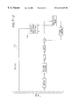
FIG. 1 illustrates a videoconferencing system implementing an embodiment of the present invention;
FIG. 2 illustrates in block diagram form an embodiment of an encoding arrangement according to the present invention;
FIG. 3 illustrates in block diagram form an embodiment of a decoding arrangement, according to the present invention, that is useful for decoding images sourced from the encoding arrangement of FIG. 2 and generally consistent with other ones of the illustrated encoding/decoding methods and processes discussed below;
FIG. 4 illustrates in block diagram form another embodiment of an encoding arrangement according to the present invention;
FIG. 5 illustrates in block diagram form another embodiment of an encoding arrangement according to the present invention;
FIG. 6 illustrates in block diagram form another embodiment of an encoding arrangement according to the present invention;
FIG. 7 illustrates in block diagram form another embodiment of an encoding/decoding arrangement according to the present invention;
FIGS. 8A and 8B illustrate in graphic form characteristics of respective transform loops according to particular embodiments of the present invention; and
FIG. 9 illustrates in block diagram form another embodiment of an encoding/decoding arrangement according to the present invention.
While the invention is amenable to various modifications and alternative forms, specifics thereof have been shown by way of example in the drawings and will be described in detail. It should be understood, however, that the intention is not to limit the invention to the particular embodiment described. On the contrary, the invention is to cover all modifications, equivalents, and alternatives falling within the spirit and scope of the invention as defined by the appended claims.
DETAILED DESCRIPTION OF THE VARIOUS EXAMPLE EMBODIMENTS
The present invention is believed to be applicable to a variety of systems and arrangements that transmit and decode compressed images. The present invention has been found to be particularly advantageous in videoconferencing applications in which the reconstruction algorithms of the compressor encoder and compressor decoder are not identical. A particular example application is an application intending to be compliant with the ITU-T H.263 Annex J recommendation where the accuracy of the prediction operation at the communicating terminals is defined using statistical data, rather than a bit-exact or operation-specific methodology at both ends. While the present invention is not necessarily limited to such applications, an appreciation of various aspects of the invention is best gained through a discussion of example arrangements operating in this type of application.
In connection with the present invention, it has been discovered that the nature of the ITU-TH.263 Annex J recommendation permits the accumulation of seemingly negligible differences between transmitting codec's prediction frames and the receiving codec's prediction frames, therefore resulting in significant distortion of the receiving codec's decoded images. This occurs even though mismatched inverse transformations, in this case IDCTs, are compliant according to ITU-T H.263 Annex A (“Inverse Transform Accuracy Specification”).
The problem can be best understood by referring to an example image-communication system, such as the videoconferencing system 10 of FIG. 1 and the other illustrated encoding and decoding arrangements.
FIG. 1 illustrates an example videoconferencing system 10 particularly suited for use in connection with the present invention. A first videoconferencing station 12 includes a first terminal 14 that receives images from a camera 16. The images are processed by a codec in the terminal 14 and are transmitted over a communications channel 20. For example, the images may be transmitted over a telephone line, an ISDN line, an Internet channel, or a similar communications network. The images are then received by a second videoconferencing station 22, including a second terminal configured to be compatible with the first terminal. To facilitate the discussion below, the first and second terminals 14 and 24 are respectively referred to as local and remote terminals. It should be understood, however, that the features described can be incorporated into either or both terminals. The remote videoconferencing station 22 may further include a camera 26 and a codec 28. The remote videoconferencing station 22 receives the images over the communications channel 20 from the local videoconferencing station 12 and decodes them using the codec 28. The decoded images may be displayed on a display monitor 30. In this manner, meetings can be conducted, for example, with participants separated by long distances with all meeting participants able to see each other.
FIG. 2 illustrates another embodiment of an encoding arrangement 300 that is particularly suited for use in the present invention. An original image is stored in a memory 301, such as a frame buffer. The original image is received by a summing element 302, which is configured and arranged to calculate difference information representing the difference between the original image and an image stored in a memory 304, such as a frame buffer. When no image is initially stored in the memory 304, the original image is passed to a transformation block 306, which transforms the image into coefficient data selected from a continuous range of values. In the illustrated example, the transformation block 306 performs a discrete cosine transform (DCT) on the original image. To encode a stream of images, the original image is replaced with successive frames after encoding each frame.
The coefficient data is further transformed by a transformation block, illustrated as a quantizer 308, which is controlled by a coding control block 310. The quantizer 308 maps the coefficient data to a discrete set of values by dividing the continuous range of values into a set of non-overlapping subranges. Each subrange is mapped to a single value, such that whenever a coefficient falls within a given subrange, the quantizer 308 generates the corresponding discrete value. The size of the subranges and the quality of the quantization are controlled by the coding control block 310.
The quantized data thus generated is encoded by an encoding block, illustrated as a Huffman encoder 312. For example, the quantized data may be encoded as a run length vector. The encoded data is stored in a memory 314 for transmission over a communications channel 316.
The quantized data is also received by a transformation block 318. The transformation block 318, implemented as an inverse quantizer in the illustrated example, maps the quantized data to a continuous range of values. The quality of the inverse quantization is controlled by the coding control block 310. A second transformation block 320 further transforms the quantized data using an inverse discrete cosine transform (IDCT) to reconstruct the image as it would be seen at a remote videoconferencing station.
Using a loop filter 303 to smooth out transitions at image block boundaries, the reconstructed image is incorporated into the image previously stored in the memory 304 by a summing element 322, and the image thus produced is stored in the memory 304 as the new reference frame for encoding the next frame. The memory 304 provides the reconstructed image to the summing element 302, and the process is repeated, either by continuing to encode successive frames of video, or by progressively improving a single still image.
FIG. 3 illustrates another embodiment of a decoding arrangement 400, also including a loop filter like the loop filter of FIG. 2, that is also particularly suited for use in the present invention. A data stream received over a communications channel 402 is stored in a memory 404, implemented as a buffer in the illustrated example. A decoder, illustrated as a Huffman decoder 406, decodes the data stream into image data and provides the image data to a transformation block 408. The transformation block 408, implemented as an inverse quantizer in the illustrated example, maps the image data to a continuous range of values. A second transformation block 410 further transforms the continuous value using an inverse discrete cosine transform (IDCT) to reconstruct the difference information received from the local terminal. A summing element 414 integrates the difference information into the image previously stored in a memory 412, depicted as a frame buffer, and the image is filtered by a loop filter 411 (constructed similar to the loop filter 303 of FIG. 2). The image thus produced is stored in the memory 412 and displayed by a display device 413. Additional data received over the communications channel 402 is integrated into the stored image to improve its quality.
It has been discovered in connection with the present invention that visually apparent divergence artifacts occur and that the visual artifacts worsen over time when the ITU-T H.263 Annex J loop filter is used in the case where the encoder IDCT differs from the decoder IDCT. Differences between sending codec and receiving codec IDCTs may arise due to difference in how many bits of precision are used in the arithmetic operations of the specific implementation of the IDCT, even though both IDCTs are H.263 Annex A compliant. Furthermore, the artifacts do not occur if the loop filter is turned off. It is therefore likely that the loop filter may enhance the mismatch between encoder and decoder IDCT.
To reproduce these described divergence artifacts, reference may be made to document Q15-D-41 submitted to the ITU-T Study Group 16 (paper dated Apr. 13, 1998). These divergence artifacts were discovered using the following setup:
Encoder: UBC encoder tmn-3.1.2 using their floating point IDCT, with Annex J enabled. For simplicity, only enable loop filter with Annex J, and keep unrestricted motion vector mode and four motion vector modes OFF.
>tmn -i rawseq -B bs-q I-a 0 -b 99 -q 2 -A 2 -k 0-1
Decoder: UBC decoder tmndec-3.1.2 using a modified fixed-point IDCT. The fixed-point IDCT was modified to make it H.263 Annex A compliant and is listed in Appendix A.
>tmndec -o4 -x -1 bs-q I -j
Test sequence: A one hundred frame natural sequence showing a stationary color grid is included in a file entitled “rawseq” as discussed in the above-referenced paper submitted to the ITU-T.
The above simulations were used on the included dataset for QP values ranging from 1 to 31. Included in q15d41ab.tar.gz are coded bitstreams where Annex J is both on and off (bs-q1-j, bs-q1), with QP=1.
For low QPs (O<QP<5), obvious divergence patterns appear along edges. For QP=1 (bs-q1-j) a vertical line along the right edge of the yellow patch, as well as spots along the 8×8 block boundaries in the lower right blue patch appear. When QP is increased, the patterns become blurred, but divergence patterns are still noticeable along the edges of the green center-low patch and the blue right-low patch up to QP=4.
Note that the INTRA MB refresh rule (threshold=132 coded MBs) does not prevent artifacts with the test sequence since the threshold is not reached. In general, even if the threshold is reached, divergence may have already leaked into other MBs under the following conditions: (1) uncoded blocks that border coded blocks are filtered based on the pixels in the coded blocks; these uncoded blocks are not fixed by the refresh since their threshold are never triggered; and (2) Mvs of neighboring MBs may reference areas of divergence, the neighboring MBs are not fixed by the refresh if they stop referencing the refreshed MB.
Condition (1) is specific to the loop filter and gives rise to an interesting scenario. Refreshing a MB may not even fix divergence within the refreshed MB since the loop filter may immediately pull in divergence errors just outside the MB boundaries.
The observed visual artifacts indicate that the loop filter is not stable in a control sense; i.e., a small difference in the encoder/decoder is amplified by the filter. This amplification is demonstrated for a specific range of the filter in the following example.
The deblock equations are:
Bi=clip(B+di)
C1=clip(C−di)
A1=A−d2
DI=D+d2
d=(A−4B+4C−D)/g
dI=UpDownRamp(d, STRENGTH)
d2=clipd I ((A−D)/4, d ½)
Consider the case where A=D, and for simplicity no clipping is required. Then the equations are:
BI=B+dI
C1=C−d1
A1=A
DI=D
d=(C−B)/2
d I=UpDownRainp((C−B)/2, STRENGTH)
d2=0
Note that only B and C get updated by the deblock filter.
Assume the encoder has
C′−B′>0
and the decoder has
C″−B″>0
and that there is a slight encoder/decoder IDCT mismatch such that ( C - B ) 2 d - ( C - B ) 2 d = A > 0
Figure US06215425-20010410-M00001
If these (d′, d″) are in the negative slope range of the UpDownRamp, then di′>di″. Now since
C1′−B1″=(C′−B′)−2d1′
C1″−BI″=(C″−B″)−2d1″
the encoder/decoder mismatch after the deblock filter will be: A1 ( Cl - BI ) - ( C1 - BI )       ( C - B ) - ( C - B ) - 2 di + 2 d1         A + 2 ( d1 - di )
Figure US06215425-20010410-M00002
The quantity (d I′−d I″) is positive and therefore
A1>A
which implies that the filter amplifies the encoder/decoder mismatch.
The present invention addresses this discovered problem using one or more of the embodiments that are discussed below.
According to one implementation, the present invention provides a method for encoding and decoding involving the use of an inverse transform that is specified bit-exactly in encoder and decoder. For example, the encoding/decoding arrangement of FIGS. 2 and 3 provide this approach, using a specified bit-exact match. This avoids encoder/decoder inverse transform mismatch, thereby eliminating divergence artifacts.
According to another implementation, the present invention provides a method for encoding and decoding involving the use of an inverse transform that is specified bit-exactly in encoder and decoder, as described above, but the inverse transform is selected at the run-time from a set of available inverse transforms. The communicating terminals then negotiate to reach a common inverse transform so that encoder/decoder inverse transforms are matched, thereby eliminating divergence artifacts. FIGS. 2 and 3 illustrate an alternative encoding/decoding arrangement, according to the present invention, using an optional inverse transform selector at each end to provide the appropriate matching.
According to another implementation, the present invention provides a method for encoding and decoding involving the step of pre-processing image data before encoding in the loop. For example, by applying a filter to the entire image, or selectively in regions that may give rise to divergence artifacts, any potential inverse transform mismatch being significantly enhanced by the loop filter is prevented to reduce divergence artifacts. Such an implementation is shown in FIG. 4, where the input data supplied by the camera 450 is filtered at filter 452 before presentation to the encoder 454 to avoid divergence build-up.
According to another implementation, the present invention provides a method for encoding and decoding involving the use of a modified encoding arrangement to reduce errors. Example implementations include one or more of the following: an encoding arrangement that selects a quantization value which is less prone to divergence; an encoding arrangement that adjusts transform coefficients to limit divergence; an encoding arrangement that adjusts the encoding mode decision for macroblocks; and an encoding arrangement that uses combinations of the above approaches. Such an implementation is shown in FIG. 5, where an anti-divergence encoding adjustment block 460 is used to provide one or more of these adjustments or selections.
As shown by way of example in the encoding arrangement of FIG. 6, another embodiment of the present invention involves the encoding arrangement determining at block 470 which portions of the image are diverging. These portions are INTRA coded (refreshed) to terminate any divergence. The refresh is accomplished by coding the regions in INTRA mode, with no dependencies on previous reference data.
In yet another embodiment of the present invention and as shown by way of example in FIG. 7, a conventional encoding arrangement is modified as above to refresh portions of the image that are diverging and coding the regions in INTRA mode, but based on information conveyed from the decoder via a feedback channel, such as a channel 472 carrying control data between encoder refresh controller 474 and decoder deblocking feedback controller 476. The information may include, for example, copies of the decoder's reference frame at a particular time, or portions thereof. This similarly terminates divergence artifacts before they become significant.
According to another implementation and as shown by way of example in FIGS. 8A and 8B, the modified set of loop filter characteristics shown in FIG. 8B are used rather than the ITU-T set of FIG. 8A so that inverse transform mismatches are not amplified. One or more of the loop filter equations, the strength table, and the definition of the UpDownRamp curve, are adjusted to reduce loop filter amplification of inverse transform mismatch.
In connection with FIG. 8A, according to ITU-T H.263 Annex J,
d1=UpDownRamp(d, Strength), where UpDownRamp(x, Strength) =sign (x) * (MAX (0, abs(x)−MAX(0, 2 * (abs(x)−Strenth)))).
In connection with FIG. 8B, a modified curve may be used instead, e.g.,
d1=ModifiedRamp(d, Strength), where ModifiedRamp(x, Strength)=SIGN (x) * MIN(abs(k), Strength).
In another embodiment, the encoding arrangement is adaptively modified depending on the motion in the scene. A more particular embodiment involves such adaptive modification applied non-uniformly to luma and chroma components of the image data. In an alternative particular embodiment, such adaptive modification is applied uniformly to luma and chroma components of the image data. Using either of these particular implementations, the adjustments to the encoder behavior reduce divergence artifacts.
According to yet another implementation implementation and as shown by way of example in FIG. 9, the loop filter is applied to the frame buffer image just before sending the data to a display circuit, but the results are not written back to the frame buffer. This moves the loop filter out of the codec loop and preserves some of the benefits of deblocking, but any deblocking amplification of inverse transform mismatch is not fed back to avoid error build up and to eliminate divergence artifacts.
Accordingly, the present invention provides various implementations that solve a significant problem discovered in connection herewith. According to particular implementations, an encoding/decoding method and arrangement uses an inverse transform loop having a decoding algorithm that: is susceptible to accumulating error due to inverse transformer mismatch with the method and arrangement providing control to maintain the accumulation below an acceptable threshold; and/or eliminates the possibility of such an error being accumulated within the loop.
For further information concerning the construction and operation of the encoding and decoding components and blocks illustrated in connection with the figures, reference may be made to U.S. patent application Ser. Nos. 08/944,311, filed Oct. 6, 1997, and No. 09/005,053, filed Jan. 9, 1998, incorporated by reference in their entirety.
The various embodiments described above are provided by way of illustration only and should not be construed to limit the invention. For example, as set forth in the claims, it will be appreciated that one or more of the above-discussed approaches can be used in combination. Those skilled in the art will readily recognize various modifications and changes which may be made to the present invention without strictly following the exemplary embodiments and applications illustrated and described herein, and without departing from the true spirit and scope of the present invention which is set forth in the following claims.

Claims (20)

What is claimed is:
1. A method for transmitting a representation of an image from a first terminal to a second terminal using a communications channel on which communication has been established between the first terminal and the second terminal, comprising:
operating each of the first and second terminals using an inverse transformer loop with a loop filter with a feedback path to the loop filter and having a decoding algorithm that accumulates error, the feedback path amplifying the error; and
controlling the amplified error to maintain the accumulation below an acceptable threshold.
2. A method, according to claim 1, wherein the step of operating using the inverse transformer loop includes using a motion estimation algorithm.
3. A method, according to claim 1, wherein at least one of the steps of operating using the inverse transformer loop and controlling includes using a bit-exact specified inverse transform algorithm relative to the respective first and second terminals.
4. A method, according to claim 1, wherein at least one of the steps of operating using the inverse transformer loop and controlling includes negotiating a selected one of a plurality of bit-exact specified inverse transform algorithms relative to the respective first and second terminals.
5. A method, according to claim 1, further including anticipating an artifact location and pre-processing data corresponding to the artifact location before accumulation can occur.
6. A method, according to claim 5, wherein the step of anticipating an artifact location includes the step of detecting a boundary between two image types.
7. A method, according to claim 5, wherein the step of anticipating an artifact location includes the step of pre-filtering.
8. A method, according to claim 1, further including changing a characteristic of the inverse transformer loop.
9. A method, according to claim 8, wherein changing a characteristic of the inverse transformer loop includes changing data correlating to a deblocker equation to a response characteristic of the inverse transformer loop.
10. A method, according to claim 8, wherein changing a characteristic of the inverse transformer loop includes changing a response characteristic of the inverse transformer loop.
11. A method, according to claim 1, further including the step of refreshing.
12. A method, according to claim 1, further including altering an input to the inverse transformer loop in response to detected or anticipated artifacts.
13. A method for encoding and decoding a representation of an image for communication between a first terminal to a second terminal, comprising:
operating each of the first and second terminals using an inverse transformer loop with a loop filter with a feedback path to the loop filter that amplifies error; and
preventing unacceptable accumulation of the amplified error within the inverse transformer loop by at least one of: pre-processing input data before using the inverse transformer loop to process the input data; using the inverse transformer in the loop according to a bit-exact specification between the encoder and decoder in the respective first and second terminals; using the inverse transformer in the loop according to one of a plurality of bit-exact specifications between the encoder and decoder in the respective first and second terminals and negotiating a common decision on the particular specification through encoder/decoder negotiation; providing a quantization valuer in the inverse transformer loop that is less prone to divergence; adjusting or providing transform coefficients to limit divergence; choosing an encoding mode for macro-blocks of input data; modifying the encoder to refresh portions of the image that are diverging; modifying the loop filter characteristics so that inverse transform mismatches are not amplified; applying the loop filter to input data corresponding to a frame buffer image just before sending to a display circuit without writing back the results to a frame buffer in the loop.
14. A decoder constructed and arranged to operate according to claim 13, comprising: an inverse transformer loop for operation according to the step of preventing.
15. A encoder constructed and arranged to operate according to claim 13, comprising: an inverse transformer loop for operation according to the step of preventing.
16. A video-conferencing terminal having a decoder constructed and arranged to operate according to claim 13, comprising: an inverse transformer loop for operation according to the step of preventing.
17. An arrangement for transmitting a representation of an image from a first terminal to a second terminal using a communications channel on which communication has been established between the first terminal and the second terminal, comprising:
means for operating each of the first and second terminals using an inverse transformer loop with a loop filter with a feedback path to the loop filter and having a decoding algorithm that accumulates error, the feedback path amplifying the error; and
means for controlling the amplified error to maintain the accumulation below an acceptable threshold.
18. An arrangement for transmitting a representation of an image from a first terminal to a second terminal using a communications channel on which communication has been established between the first terminal and the second terminal, comprising:
a processor-based decoder/encoder circuit arranged to operate each of the first and second terminals using an inverse transformer loop with a loop filter with a feedback path to the loop filter and having a decoding algorithm that accumulates error, the feedback path amplifying the error; and
means for controlling the amplified error to maintain the accumulation below an acceptable threshold.
19. A method for transmitting a representation of an image from a first terminal to a second terminal using a communications channel on which communication has been established between the first terminal and the second terminal, comprising:
operating each of the first and second terminals using an inverse transformer loop with a loop filter with a feedback path to the loop filter and having a decoding algorithm that is susceptible to accumulating an error due to a mismatch between respective inverse transformers in the first and second terminals, the feedback path amplifying the error; and
modifying input data giving rise to the amplified error before using the inverse transformer loop to process the input data.
20. A method for transmitting a representation of an image from a first terminal to a second terminal using a communications channel on which communication has been established between the first terminal and the second terminal, comprising:
providing in at least one of the first and second terminals an inverse transformer loop having a decoding algorithm and a loop filter outside of the transformer loop, the loop filter with a feedback path to the loop filter and the feedback path amplifying the error; and
operating each of the first and second terminals using the inverse transformer loop and the loop filter.
US09/064,397 1992-02-19 1998-04-22 Deblocking filter for encoder/decoder arrangement and method with divergence reduction Expired - Lifetime US6215425B1 (en)

Priority Applications (4)

Application Number Priority Date Filing Date Title
US09/064,397 US6215425B1 (en) 1992-02-19 1998-04-22 Deblocking filter for encoder/decoder arrangement and method with divergence reduction
US09/112,612 US6160503A (en) 1992-02-19 1998-07-09 Deblocking filter for encoder/decoder arrangement and method with divergence reduction
US09/250,891 US6225923B1 (en) 1992-02-19 1999-02-16 Encoder arrangement and bit-exact IDCT protocol
US09/734,280 US6404361B2 (en) 1992-02-19 2000-12-11 Deblocking filter for encoder/decoder arrangement and method with divergence reduction

Applications Claiming Priority (7)

Application Number Priority Date Filing Date Title
US07/838,382 US5379351A (en) 1992-02-19 1992-02-19 Video compression/decompression processing and processors
US30397394A 1994-09-09 1994-09-09
US65891796A 1996-05-31 1996-05-31
US08/908,826 US5790712A (en) 1992-02-19 1997-08-08 Video compression/decompression processing and processors
US09/005,053 US6124882A (en) 1992-02-19 1998-01-09 Videocommunicating apparatus and method therefor
US09/064,397 US6215425B1 (en) 1992-02-19 1998-04-22 Deblocking filter for encoder/decoder arrangement and method with divergence reduction
US09/098,106 US6441842B1 (en) 1992-02-19 1998-06-16 Video compression/decompression processing and processors

Related Parent Applications (4)

Application Number Title Priority Date Filing Date
US09/005,053 Continuation US6124882A (en) 1989-01-30 1998-01-09 Videocommunicating apparatus and method therefor
US09/005,053 Continuation-In-Part US6124882A (en) 1989-01-30 1998-01-09 Videocommunicating apparatus and method therefor
US09/098,106 Continuation-In-Part US6441842B1 (en) 1992-02-19 1998-06-16 Video compression/decompression processing and processors
US09/098,106 Continuation US6441842B1 (en) 1992-02-19 1998-06-16 Video compression/decompression processing and processors

Related Child Applications (2)

Application Number Title Priority Date Filing Date
US09/098,106 Continuation-In-Part US6441842B1 (en) 1992-02-19 1998-06-16 Video compression/decompression processing and processors
US09/112,612 Continuation-In-Part US6160503A (en) 1992-02-19 1998-07-09 Deblocking filter for encoder/decoder arrangement and method with divergence reduction

Publications (1)

Publication Number Publication Date
US6215425B1 true US6215425B1 (en) 2001-04-10

Family

ID=46255954

Family Applications (1)

Application Number Title Priority Date Filing Date
US09/064,397 Expired - Lifetime US6215425B1 (en) 1992-02-19 1998-04-22 Deblocking filter for encoder/decoder arrangement and method with divergence reduction

Country Status (1)

Country Link
US (1) US6215425B1 (en)

Cited By (24)

* Cited by examiner, † Cited by third party
Publication number Priority date Publication date Assignee Title
US6404361B2 (en) * 1992-02-19 2002-06-11 Netergy Microelectronics, Inc. Deblocking filter for encoder/decoder arrangement and method with divergence reduction
US20030044080A1 (en) * 2001-09-05 2003-03-06 Emblaze Systems Ltd Method for reducing blocking artifacts
US20030138150A1 (en) * 2001-12-17 2003-07-24 Microsoft Corporation Spatial extrapolation of pixel values in intraframe video coding and decoding
US20030185452A1 (en) * 1996-03-28 2003-10-02 Wang Albert S. Intra compression of pixel blocks using predicted mean
US20030206587A1 (en) * 2002-05-01 2003-11-06 Cristina Gomila Chroma deblocking filter
US20030206664A1 (en) * 2002-05-01 2003-11-06 Cristina Gomila Deblocking filter conditioned on pixel brightness
US20030219074A1 (en) * 2002-01-31 2003-11-27 Samsung Electronics Co., Ltd. Filtering method for removing block artifacts and/or ringing noise and apparatus therefor
US20050013494A1 (en) * 2003-07-18 2005-01-20 Microsoft Corporation In-loop deblocking filter
NO20042477A (en) * 2004-06-14 2005-10-17 Tandberg Telecom As Chroma de-blocking procedure
US20050259877A1 (en) * 1997-05-05 2005-11-24 Wang Albert S Intra compression of pixel blocks using predicted mean
US20060023791A1 (en) * 2004-07-29 2006-02-02 Samsung Electronics Co., Ltd. Method and apparatus for decoding moving picture to which post filtering is applied
EP1667461A2 (en) * 2004-11-05 2006-06-07 STMicroelectronics S.r.l. A method for block coding of a flow of data, in particular video data, and corresponding device and computer-program product
US20070116116A1 (en) * 1999-09-27 2007-05-24 Bernd Sostawa Digital transcoding system
US20080084932A1 (en) * 2006-10-06 2008-04-10 Microsoft Corporation Controlling loop filtering for interlaced video frames
US7616829B1 (en) 2003-10-29 2009-11-10 Apple Inc. Reducing undesirable block based image processing artifacts by DC image filtering
US8787443B2 (en) 2010-10-05 2014-07-22 Microsoft Corporation Content adaptive deblocking during video encoding and decoding
US9042458B2 (en) 2011-04-01 2015-05-26 Microsoft Technology Licensing, Llc Multi-threaded implementations of deblock filtering
US9215326B2 (en) 2002-05-20 2015-12-15 Callwave Communications, Llc Systems and methods for call processing
US9253319B1 (en) 2005-07-01 2016-02-02 Callwave Communications, Llc Methods and systems for call connecting calls
US9319523B2 (en) 1999-04-01 2016-04-19 Callwave Communications, Llc Methods and apparatus for providing expanded telecommunications service
US9413885B1 (en) 2006-10-06 2016-08-09 Callwave Communications, Llc Methods and systems for blocking unwanted communications
US10091533B2 (en) 2016-02-18 2018-10-02 Cisco Technology, Inc. Generalized filter for removing video compression artifacts
US10110926B2 (en) 2015-10-15 2018-10-23 Cisco Technology, Inc. Efficient loop filter for video codec
US10958917B2 (en) 2003-07-18 2021-03-23 Microsoft Technology Licensing, Llc Decoding jointly coded transform type and subblock pattern information

Citations (4)

* Cited by examiner, † Cited by third party
Publication number Priority date Publication date Assignee Title
US5604502A (en) * 1994-03-21 1997-02-18 Lucent Technologies Inc. Motion video compression system with inverse discrete cosine transform mismatch control
US5635938A (en) * 1993-12-28 1997-06-03 Oki Electric Industry Co., Ltd. Quantizing and dequantizing circuit with reduced size
US5736944A (en) * 1995-04-14 1998-04-07 Kabushiki Kaisha Toshiba Image decoding apparatus
US5872866A (en) * 1995-04-18 1999-02-16 Advanced Micro Devices, Inc. Method and apparatus for improved video decompression by predetermination of IDCT results based on image characteristics

Patent Citations (4)

* Cited by examiner, † Cited by third party
Publication number Priority date Publication date Assignee Title
US5635938A (en) * 1993-12-28 1997-06-03 Oki Electric Industry Co., Ltd. Quantizing and dequantizing circuit with reduced size
US5604502A (en) * 1994-03-21 1997-02-18 Lucent Technologies Inc. Motion video compression system with inverse discrete cosine transform mismatch control
US5736944A (en) * 1995-04-14 1998-04-07 Kabushiki Kaisha Toshiba Image decoding apparatus
US5872866A (en) * 1995-04-18 1999-02-16 Advanced Micro Devices, Inc. Method and apparatus for improved video decompression by predetermination of IDCT results based on image characteristics

Non-Patent Citations (1)

* Cited by examiner, † Cited by third party
Title
ITU-T H.263 Annex J. and full "Draft Text of Recommendation H-263 Version 2 ("H.263+") For Decision".

Cited By (68)

* Cited by examiner, † Cited by third party
Publication number Priority date Publication date Assignee Title
US6404361B2 (en) * 1992-02-19 2002-06-11 Netergy Microelectronics, Inc. Deblocking filter for encoder/decoder arrangement and method with divergence reduction
US20030185452A1 (en) * 1996-03-28 2003-10-02 Wang Albert S. Intra compression of pixel blocks using predicted mean
US7162091B2 (en) 1996-03-28 2007-01-09 Microsoft Corporation Intra compression of pixel blocks using predicted mean
US7181072B2 (en) 1997-05-05 2007-02-20 Microsoft Corporation Intra compression of pixel blocks using predicted mean
US20050259877A1 (en) * 1997-05-05 2005-11-24 Wang Albert S Intra compression of pixel blocks using predicted mean
US9319523B2 (en) 1999-04-01 2016-04-19 Callwave Communications, Llc Methods and apparatus for providing expanded telecommunications service
US9647978B2 (en) 1999-04-01 2017-05-09 Callwave Communications, Llc Methods and apparatus for providing expanded telecommunications service
US20070116116A1 (en) * 1999-09-27 2007-05-24 Bernd Sostawa Digital transcoding system
US7936816B2 (en) 1999-09-27 2011-05-03 Harman Becker Automotive Systems Gmbh Digital transcoding system
US7426315B2 (en) 2001-09-05 2008-09-16 Zoran Microelectronics Ltd. Method for reducing blocking artifacts
US20090028459A1 (en) * 2001-09-05 2009-01-29 Zoran Corporation Method for reducing blocking artifacts
US7706627B2 (en) 2001-09-05 2010-04-27 Zoran Corporation Method for reducing blocking artifacts
US20030044080A1 (en) * 2001-09-05 2003-03-06 Emblaze Systems Ltd Method for reducing blocking artifacts
US8908768B2 (en) 2001-12-17 2014-12-09 Microsoft Corporation Video coding / decoding with motion resolution switching and sub-block transform sizes
US9456216B2 (en) 2001-12-17 2016-09-27 Microsoft Technology Licensing, Llc Sub-block transform coding of prediction residuals
US20060126955A1 (en) * 2001-12-17 2006-06-15 Microsoft Corporation Spatial extrapolation of pixel values in intraframe video coding and decoding
US20060215919A1 (en) * 2001-12-17 2006-09-28 Microsoft Corporation Spatial extrapolation of pixel values in intraframe video coding and decoding
US7116830B2 (en) * 2001-12-17 2006-10-03 Microsoft Corporation Spatial extrapolation of pixel values in intraframe video coding and decoding
US9258570B2 (en) 2001-12-17 2016-02-09 Microsoft Technology Licensing, Llc Video coding / decoding with re-oriented transforms and sub-block transform sizes
US9432686B2 (en) 2001-12-17 2016-08-30 Microsoft Technology Licensing, Llc Video coding / decoding with motion resolution switching and sub-block transform sizes
US7577305B2 (en) 2001-12-17 2009-08-18 Microsoft Corporation Spatial extrapolation of pixel values in intraframe video coding and decoding
US7263232B2 (en) 2001-12-17 2007-08-28 Microsoft Corporation Spatial extrapolation of pixel values in intraframe video coding and decoding
US8817868B2 (en) 2001-12-17 2014-08-26 Microsoft Corporation Sub-block transform coding of prediction residuals
US8743949B2 (en) 2001-12-17 2014-06-03 Microsoft Corporation Video coding / decoding with re-oriented transforms and sub-block transform sizes
US10075731B2 (en) 2001-12-17 2018-09-11 Microsoft Technology Licensing, Llc Video coding / decoding with re-oriented transforms and sub-block transform sizes
US10123038B2 (en) 2001-12-17 2018-11-06 Microsoft Technology Licensing, Llc Video coding / decoding with sub-block transform sizes and adaptive deblock filtering
US10158879B2 (en) 2001-12-17 2018-12-18 Microsoft Technology Licensing, Llc Sub-block transform coding of prediction residuals
US10390037B2 (en) 2001-12-17 2019-08-20 Microsoft Technology Licensing, Llc Video coding/decoding with sub-block transform sizes and adaptive deblock filtering
US20030138150A1 (en) * 2001-12-17 2003-07-24 Microsoft Corporation Spatial extrapolation of pixel values in intraframe video coding and decoding
US8160138B2 (en) 2002-01-31 2012-04-17 Samsung Electronics Co., Ltd. Filtering method for removing block artifacts and/or ringing noise and apparatus therefor
US20070269128A1 (en) * 2002-01-31 2007-11-22 Park Jeong-Hoon Filtering method for removing block artifacts and/or ringing noise and apparatus therefor
US7630437B2 (en) * 2002-01-31 2009-12-08 Samsung Electronics Co., Ltd. Filtering method for removing block artifacts and/or ringing noise and apparatus therefor
US20090190657A1 (en) * 2002-01-31 2009-07-30 Samsung Electronics Co., Ltd. Filtering method for removing block artifacts and/or ringing noise and apparatus therefor
US20030219074A1 (en) * 2002-01-31 2003-11-27 Samsung Electronics Co., Ltd. Filtering method for removing block artifacts and/or ringing noise and apparatus therefor
US7561623B2 (en) * 2002-01-31 2009-07-14 Samsung Electronics Co., Ltd. Filtering method for removing block artifacts and/or ringing noise and apparatus therefor
US9538201B2 (en) 2002-01-31 2017-01-03 Samsung Electronics Co., Ltd. Filtering method for removing block artifacts and/or ringing noise and apparatus therefor
US8290039B2 (en) 2002-01-31 2012-10-16 Samsung Electronics Co., Ltd. Filtering method for removing block artifacts and/or ringing noise and apparatus therefor
US8699568B2 (en) 2002-01-31 2014-04-15 Samsung Electronics Co., Ltd. Filtering method for removing block artifacts and/or ringing noise and apparatus therefor
US9467714B2 (en) 2002-01-31 2016-10-11 Samsung Electronics Co., Ltd. Filtering method for removing block artifacts and/or ringing noise and apparatus therefor
US9258574B2 (en) 2002-01-31 2016-02-09 Samsung Electronics Co., Ltd. Filtering method for removing block artifacts and/or ringing noise and apparatus therefor
US20030206664A1 (en) * 2002-05-01 2003-11-06 Cristina Gomila Deblocking filter conditioned on pixel brightness
US7319415B2 (en) 2002-05-01 2008-01-15 Thomson Licensing Chroma deblocking filter
US6907079B2 (en) 2002-05-01 2005-06-14 Thomson Licensing S.A. Deblocking filter conditioned on pixel brightness
US20030206587A1 (en) * 2002-05-01 2003-11-06 Cristina Gomila Chroma deblocking filter
US9215326B2 (en) 2002-05-20 2015-12-15 Callwave Communications, Llc Systems and methods for call processing
US9917953B2 (en) 2002-05-20 2018-03-13 Callwave Communications, Llc Systems and methods for call processing
US20050013494A1 (en) * 2003-07-18 2005-01-20 Microsoft Corporation In-loop deblocking filter
US10958917B2 (en) 2003-07-18 2021-03-23 Microsoft Technology Licensing, Llc Decoding jointly coded transform type and subblock pattern information
US7616829B1 (en) 2003-10-29 2009-11-10 Apple Inc. Reducing undesirable block based image processing artifacts by DC image filtering
NO20042477A (en) * 2004-06-14 2005-10-17 Tandberg Telecom As Chroma de-blocking procedure
WO2005122588A1 (en) * 2004-06-14 2005-12-22 Tandberg Telecom As Method for chroma deblocking
US20060018386A1 (en) * 2004-06-14 2006-01-26 Tandberg Telecom As Method for chroma deblocking
US7822125B2 (en) 2004-06-14 2010-10-26 Tandberg Telecom As Method for chroma deblocking
US20060023791A1 (en) * 2004-07-29 2006-02-02 Samsung Electronics Co., Ltd. Method and apparatus for decoding moving picture to which post filtering is applied
EP1667461A2 (en) * 2004-11-05 2006-06-07 STMicroelectronics S.r.l. A method for block coding of a flow of data, in particular video data, and corresponding device and computer-program product
US9253319B1 (en) 2005-07-01 2016-02-02 Callwave Communications, Llc Methods and systems for call connecting calls
US9413885B1 (en) 2006-10-06 2016-08-09 Callwave Communications, Llc Methods and systems for blocking unwanted communications
US9692891B1 (en) 2006-10-06 2017-06-27 Callwave Communications, Llc Methods and systems for blocking unwanted communications
US20080084932A1 (en) * 2006-10-06 2008-04-10 Microsoft Corporation Controlling loop filtering for interlaced video frames
US10284868B2 (en) 2010-10-05 2019-05-07 Microsoft Technology Licensing, Llc Content adaptive deblocking during video encoding and decoding
US8787443B2 (en) 2010-10-05 2014-07-22 Microsoft Corporation Content adaptive deblocking during video encoding and decoding
US10051290B2 (en) 2011-04-01 2018-08-14 Microsoft Technology Licensing, Llc Multi-threaded implementations of deblock filtering
US9042458B2 (en) 2011-04-01 2015-05-26 Microsoft Technology Licensing, Llc Multi-threaded implementations of deblock filtering
US10110926B2 (en) 2015-10-15 2018-10-23 Cisco Technology, Inc. Efficient loop filter for video codec
US10477248B2 (en) 2015-10-15 2019-11-12 Cisco Technology, Inc. Efficient loop filter for video codec
US10091533B2 (en) 2016-02-18 2018-10-02 Cisco Technology, Inc. Generalized filter for removing video compression artifacts
US10477250B2 (en) 2016-02-18 2019-11-12 Cisco Technology, Inc. Generalized filter for removing video compression artifacts
US10986374B2 (en) 2016-02-18 2021-04-20 Cisco Technology, Inc. Generalized filter for removing video compression artifacts

Similar Documents

Publication Publication Date Title
US6404361B2 (en) Deblocking filter for encoder/decoder arrangement and method with divergence reduction
US6215425B1 (en) Deblocking filter for encoder/decoder arrangement and method with divergence reduction
US4723161A (en) Method and arrangement of coding digital image signals utilizing interframe correlation
US7580584B2 (en) Adaptive multiple quantization
US7170938B1 (en) Rate control method for video transcoding
Chin et al. A software-only videocodec using pixelwise conditional differential replenishment and perceptual enhancements
CN113632490A (en) Nonlinear adaptive loop filtering in video processing
US6075554A (en) Progressive still frame mode
WO2005079073A1 (en) Encoding and decoding of video images based on a quantization with an adaptive dead-zone size
US6028965A (en) Method and apparatus for intelligent codec system
US6865229B1 (en) Method and apparatus for reducing the “blocky picture” effect in MPEG decoded images
US7095448B2 (en) Image processing circuit and method for modifying a pixel value
US20050238096A1 (en) Fractional quantization step sizes for high bit rates
US20120087411A1 (en) Internal bit depth increase in deblocking filters and ordered dither
JP3316157B2 (en) Post-filtering method and apparatus
US6225923B1 (en) Encoder arrangement and bit-exact IDCT protocol
US6879723B1 (en) Method and apparatus for encoding frames of image data at a varying quality level
KR100229796B1 (en) Image decoding system including compensation at detoriorate image
Chai et al. Foreground/background video coding scheme
US5812200A (en) Method and apparatus for constant data rate output of encoders
Ngan et al. Very low bit rate video coding using H. 263 coder
JPH0998421A (en) Image encoding/decoding device
US8175151B2 (en) Encoders and image encoding methods
JP2504266B2 (en) Adaptive coding control method for video signals
Ilgin et al. Image and Video Compression Artifact Reduction at Low Bit Rates Using Local Cosine Transform in Conjunction with Significance Map Coding

Legal Events

Date Code Title Description
AS Assignment

Owner name: 8 X 8, INC., CALIFORNIA

Free format text: ASSIGNMENT OF ASSIGNORS INTEREST;ASSIGNORS:ANDREWS, BARRY D.;BRYANT, STEPHANE;CHIANG, MAY SHU-PEI;AND OTHERS;REEL/FRAME:009382/0584;SIGNING DATES FROM 19980716 TO 19980725

STCF Information on status: patent grant

Free format text: PATENTED CASE

AS Assignment

Owner name: NETERGY MICROELECTRONICS, INC., CALIFORNIA

Free format text: ASSIGNMENT OF ASSIGNORS INTEREST;ASSIGNOR:NETERGY NETWORKS, INC. (NOW 8X8, INC.);REEL/FRAME:012513/0184

Effective date: 20010504

AS Assignment

Owner name: 8X8, INC., CALIFORNIA

Free format text: ASSIGNMENT OF ASSIGNORS INTEREST;ASSIGNOR:NETERGY MICROELECTRONICS, INC.;REEL/FRAME:013835/0116

Effective date: 20030311

FPAY Fee payment

Year of fee payment: 4

CC Certificate of correction
FPAY Fee payment

Year of fee payment: 8

FPAY Fee payment

Year of fee payment: 12