US6233215B1 - Door assembly for a cartridge handling device - Google Patents
Door assembly for a cartridge handling device Download PDFInfo
- Publication number
- US6233215B1 US6233215B1 US08/491,538 US49153895A US6233215B1 US 6233215 B1 US6233215 B1 US 6233215B1 US 49153895 A US49153895 A US 49153895A US 6233215 B1 US6233215 B1 US 6233215B1
- Authority
- US
- United States
- Prior art keywords
- door
- opening
- access
- movement
- cartridge
- Prior art date
- Legal status (The legal status is an assumption and is not a legal conclusion. Google has not performed a legal analysis and makes no representation as to the accuracy of the status listed.)
- Expired - Lifetime
Links
- 230000033001 locomotion Effects 0.000 claims abstract description 42
- 230000007246 mechanism Effects 0.000 claims abstract description 35
- 238000000034 method Methods 0.000 claims description 16
- 230000002093 peripheral effect Effects 0.000 claims description 4
- 230000003287 optical effect Effects 0.000 abstract description 64
- 238000003780 insertion Methods 0.000 abstract description 35
- 230000037431 insertion Effects 0.000 abstract description 35
- 239000011248 coating agent Substances 0.000 description 4
- 238000000576 coating method Methods 0.000 description 4
- 230000004323 axial length Effects 0.000 description 3
- 238000013500 data storage Methods 0.000 description 3
- 210000005069 ears Anatomy 0.000 description 3
- 230000000007 visual effect Effects 0.000 description 3
- 239000004677 Nylon Substances 0.000 description 2
- 238000004883 computer application Methods 0.000 description 2
- 239000000356 contaminant Substances 0.000 description 2
- 239000002184 metal Substances 0.000 description 2
- 229920001778 nylon Polymers 0.000 description 2
- 239000004033 plastic Substances 0.000 description 2
- 239000004417 polycarbonate Substances 0.000 description 2
- 229920000515 polycarbonate Polymers 0.000 description 2
- OKTJSMMVPCPJKN-UHFFFAOYSA-N Carbon Chemical compound [C] OKTJSMMVPCPJKN-UHFFFAOYSA-N 0.000 description 1
- 229910000831 Steel Inorganic materials 0.000 description 1
- 238000005452 bending Methods 0.000 description 1
- 229910052799 carbon Inorganic materials 0.000 description 1
- 230000001419 dependent effect Effects 0.000 description 1
- 238000001514 detection method Methods 0.000 description 1
- 230000018109 developmental process Effects 0.000 description 1
- 239000000428 dust Substances 0.000 description 1
- 239000011152 fibreglass Substances 0.000 description 1
- 239000000945 filler Substances 0.000 description 1
- 210000003811 finger Anatomy 0.000 description 1
- 230000005484 gravity Effects 0.000 description 1
- 238000009434 installation Methods 0.000 description 1
- 238000004519 manufacturing process Methods 0.000 description 1
- 239000000463 material Substances 0.000 description 1
- 239000004810 polytetrafluoroethylene Substances 0.000 description 1
- 229920001343 polytetrafluoroethylene Polymers 0.000 description 1
- 238000007665 sagging Methods 0.000 description 1
- 239000010959 steel Substances 0.000 description 1
- 210000003813 thumb Anatomy 0.000 description 1
Images


Classifications
-
- G—PHYSICS
- G11—INFORMATION STORAGE
- G11B—INFORMATION STORAGE BASED ON RELATIVE MOVEMENT BETWEEN RECORD CARRIER AND TRANSDUCER
- G11B17/00—Guiding record carriers not specifically of filamentary or web form, or of supports therefor
- G11B17/02—Details
- G11B17/04—Feeding or guiding single record carrier to or from transducer unit
- G11B17/0401—Details
- G11B17/0405—Closing mechanism, e.g. door
Definitions
- the present invention relates generally to a cartridge handling device, such as an optical disk cartridge handling device and, more particularly, to a door assembly for use with a cartridge handling device.
- optical disk is a data storage medium which is readable by a laser-based reading device.
- Optical disks known as “compact disks” or “CDs” have become increasingly popular during the past few years for recording music and audio-video works.
- Due to the huge storage capacity of optical disks as compared to conventional magnetic storage media, optical disks known as “ROM disks” have become popular for storing computer readable information.
- ROM disks optical disks
- optical disks were of somewhat limited use in the computer industry due to the fact that optical disks could not be “erased” and “written” with new information, i.e. ROM disks are “read only” memory devices.
- magneto-optic disks and other types of optical disks have been developed which are both computer readable and computer writable.
- optical disks are expected to become increasingly more important in the computer industry and may eventually replace magnetically readable and writable storage media such as “floppy disks” and “hard disks.”
- magnetically readable and writable storage media such as “floppy disks” and “hard disks.”
- Another recent development, the ability to provide data storage on both surfaces of an optical disk, has effectively doubled the optical disk storage capacity.
- Optical disks of the type used in computer applications are mounted in a generally parallelepiped-shaped cartridge.
- a cartridge has a forward end which is generally provided with a ribbed surface portion which is adapted to be grasped between the thumb and index finger of an operator for handling the cartridge.
- the cartridge is adapted to be readably mounted in a conventional optical disk drive by grasping its forward end and inserting the cartridge, rear-end-first, through a narrow slot provided on the front face of a disk drive.
- optical disks are hand-inserted into disk drives.
- an optical disk storage system for storing the disks at known locations, and an optical disk handling system which is capable of retrieving a desired disk from a storage location and inserting the disk in an optical disk drive.
- a disk handling system In a disk storage system wherein stored disks and an associated disk drive are positioned in longitudinally extending storage locations arranged in a two-dimensional array consisting of vertically extending columns and horizontally extending rows, it will generally be necessary for a disk handling system to engage and move each disk longitudinally, vertically, laterally, and, again, longitudinally in order to remove it from storage, move it into aligned relationship with a disk drive, and insert it into a disk drive. It may also be necessary for the disk handling system to flip the disk to reverse the side thereof which will be positioned in readable relationship with a drive.
- an optical disk handling system be provided with a door for closing the operator access opening.
- a door may provide visual feedback to the operator indicating when a disk may be inserted.
- the handling system is ready to receive a cartridge.
- the door is closed, the system is busy and, thus not ready to receive a cartridge from the operator.
- the use of a door also prevents contaminants from entering the handling system and the optical disk storage system.
- a door to be automatic (i.e., capable of indicating when the handling system is ready to receive a cartridge), then it must be powered. In the past, this has necessitated a separate motor or other type of actuator to power the door. The addition of such a separate actuator adds cost and complexity to the handling system.
- Door opening mechanisms also tend to occupy considerable space, thus requiring an undesirable expansion of the overall storage system size envelope. Finally, it is often difficult to accurately register the handling apparatus to both the internal mechanisms of the storage apparatus and to a door opening located on the outer surface of the storage apparatus.
- the present invention is directed to a door apparatus for a cartridge handling device, such as an optical disk cartridge insertion apparatus which is adapted to be used in an optical disk storage and handling system.
- the door apparatus includes a door which automatically opens when the handling device is ready to receive or discharge a cartridge and which automatically closes when the handling device is busy and a user cannot insert a cartridge.
- the door is actuated by movement of the handling device itself. Accordingly, no additional power supply is required to operate the door. Additionally, the door actuating mechanism is constructed to operate substantially in the same plane as the existing handling device, thus minimizing the overall size of the handling device and door apparatus combination.
- the door apparatus also includes a self-aligning feature which allows the door to float with respect to the panel access opening. This reduces the need to maintain close alignment between the outer panel and the handling device.
- An aesthetically pleasing appearance, as well as a closely sealed door opening, is achieved by having the door panel fit within the door opening when the door is in the closed position.
- the door actuator mechanism operates to both retract and lift the door when opening the door.
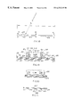
- FIG. 1 is a perspective view of a conventional optical disk cartridge.
- FIG. 2 is front perspective view of an optical disk insertion apparatus.
- FIG. 3 is rear perspective view of an optical disk insertion apparatus and portions of an associated optical disk storage and handling system.
- FIG. 4 is a top plan view of an upper housing member.
- FIG. 5 is top plan view of an optical disk cartridge carrier with a disk inserted.
- FIG. 6 is a side elevation view of the optical disk cartridge carrier of FIG. 5 .
- FIG. 7 is a top plan view of an upper housing member and an optical disk cartridge carrier located in a first operating position.
- FIG. 8 is a top plan view of an upper housing member and an optical disk cartridge carrier located in a second operating position.
- FIG. 9 is a top plan view of an optical disk insertion apparatus.
- FIG. 10 is a top plan view of an actuator used in the optical disk insertion apparatus of FIG. 9 .
- FIG. 11 is a front elevation view of the actuator of FIG. 10 .
- FIG. 12 is a front perspective view of an optical disk insertion apparatus having a door assembly in a closed position.
- FIG. 13 is a front perspective view of a portion of the door assembly of FIG. 12 with the door assembly in an open position.
- FIG. 14 is a front perspective view of a portion of the door assembly of FIG. 13 .
- FIG. 15 is a rear perspective view of an optical disk insertion apparatus having a door assembly in an open position.
- FIG. 16 is a top plan view of an optical disk insertion apparatus having a door assembly.
- FIG. 17 is a rear perspective view of an optical disk insertion apparatus having a door assembly in a closed position.
- FIG. 18 is a bottom plan view of a door member of the door assembly of FIG. 12 .
- FIG. 19 is a rear elevation detail view illustrating the connection between portions of the door assembly of FIG. 12 .
- FIG. 20 is a rear elevation detail view of the connection of FIG. 19 in a different configuration.
- FIG. 21 is a top plan view of a portion of the door assembly of FIG. 12 .
- FIGS. 12-21 illustrate a door assembly 410 for a cartridge receiving device 10 having an exteriorly located panel 412 which includes an access opening 422 therein adapted to receive cartridges 12 therethrough.
- the door assembly 410 includes a door opening mechanism 426 operatively associated with the cartridge receiving device 10 .
- a door panel 424 is provided which is adapted to close the access opening 422 .
- the door panel 424 is slidingly attached to the door opening mechanism 426 .
- the method includes the steps of retracting the door 424 away from the access opening 422 and lifting the door 424 .
- FIG. 1 A conventional optical disk cartridge 12 is illustrated in FIG. 1 .
- the optical disk cartridge has a rear end portion 14 which is adapted to be inserted into an optical disk reading device and a forward end portion 16 which is adapted to be grasped by a human operator for handling the cartridge.
- Conventional optical disk cartridges in use in the United States for computer applications have a generally parallelepiped shape with a thickness (height) of approximately 0.4 inches, a length of approximately 6 inches, and a maximum width of approximately 5.3 inches.
- the rear end portion 14 of an optical disk cartridge tapers in width somewhat in approximately the last 0.5 inch of axial length thereof from a maximum lateral dimension of 5.3 inches to a minimum lateral dimension of approximately 5.1 inches at the terminal end thereof.
- Each optical disk has symmetrically positioned recesses 19 (only one shown) in the lateral sidewalls 21 (only one shown) thereof which are adapted for engaging a portion of a reading device.
- the forward end of a conventional optical disk cartridge has a centrally positioned ribbed surface 23 (only one shown) on both a top 25 and bottom surface (not shown) thereof.
- Each optical disk also comprises a first rectangular groove 27 and a second rectangular groove 29 in a forward portion of the lateral sidewalls which are adapted to be engaged by portions of conventional reading devices for locating and holding the cartridge in the reading device.
- An optical disk may also include holes 24 and 26 which may be used for proper orientation detection.
- housing 30 may comprise an upper housing member 102 and a lower housing member 104 .
- the upper housing member 102 has a top panel portion 108 , first and second lateral sidewalls 110 , 112 , a front wall 114 , and a rear wall 116 .
- the front wall 114 includes a laterally extending opening 134 therein which may have a lateral dimension of, e.g. 145.4 mm and a height of, e.g. 10 mm.
- the side wall 110 includes an opening 135 therein, which may be, e.g., 184.39 mm wide and, e.g. 10 mm high.
- the peripheral walls 110 , 112 , 114 , 116 of the upper housing member 102 may include vertically extending bores 126 which are adapted to receive screws for attaching the upper housing member 102 to the lower housing member 104 .
- the upper housing member 102 also contains the track 60 and the actuator guide 70 .
- the lower housing member 104 comprises a bottom panel 127 , a front wall 128 , a rear wall 130 , a first lateral sidewall 132 and a second lateral sidewall, not shown.
- the front wall 128 includes a laterally extending opening 136 therein which may have a lateral dimension of, e.g. 145.4 mm and a height of, e.g. 11.8 mm.
- the side wall 132 has an opening 138 therein, which may be, e.g., 184.39 mm wide and, e.g. 11.8 mm high.
- the peripheral walls 128 , 130 , 132 of the lower housing member 104 may comprise bores 139 therein adapted to threadingly accept screws or the like for attaching the upper housing member 102 to the lower housing member 104 .
- the upper and lower housing members when attached, define a generally parallelepiped-shaped cavity which may have a lateral dimension of, e.g., 145.4 mm, a longitudinal dimension of, e.g., 257.2 mm, and a height of, e.g., 21.8 mm.
- the front opening 134 in upper housing member 102 and the front opening 136 of lower housing member 104 cooperate to form the front opening 36 in the housing 30 when the upper housing member 102 and the lower housing member 104 are assembled.
- the side opening 135 in upper housing member 102 and the side opening 138 of lower housing member 104 cooperate to form the side opening 42 in the housing 30 when the upper housing member 102 and the lower housing member 104 are assembled.
- the front opening 36 may have a lateral dimension of, e.g., 145.4 mm and a height of, e.g., 21.8 mm.
- the side opening 42 may have a lateral dimension of, e.g., 184.39 mm and a height of, e.g., 21.8 mm.
- the insertion device sliding members (track 60 and actuator guide 70 ) are located in the upper housing member 102 . Accordingly, it is desirable to construct the upper housing member 102 from a durable, high-strength plastic, such as polycarbonate with 15% carbon and 15% PTFE, in order to resist wear induced by the sliding members. Since the lower housing member 104 contains no sliding members, it may be constructed of a less expensive plastic such as polycarbonate with a 20% fiberglass filler.
- the housing 30 may also be provided with crush bumps 100 , 101 , 106 , 107 located on upper housing member 102 , FIG. 2 . These crush bumps facilitate installation of the housing into the optical disk storage and handling system 11 . When the housing 30 is inserted into a closely fitting handling system receptacle, the crush bumps 100 , 101 , 106 , 107 are able to shear away to configure to the exact size of the receptacle. This greatly facilitates alignment between the housing 30 and its associated handling system 11 . Similar crush bumps, not shown, may also be provided on the lower housing member 104 .
- the cartridge carrier 40 comprises an upper member 150 and a lower member 170 .
- Upstanding rear wall 176 and two upstanding lateral sidewalls 178 , 180 connect the upper member 150 to the lower member 170 .
- Cartridge carrier 40 may have a longitudinal length of, e.g., 118.04 mm and a lateral width of, e.g., 142.1 mm, as viewed in FIG. 5 .
- the upper member 150 of cartridge carrier 40 comprises a generally flat, horizontal panel 152 .
- the upper member 150 also comprises an upstanding stud member 162 which is adapted to ride in track 60 , as described in further detail below.
- Stud 162 may have a diameter of, e.g., 5.8 mm and an axial length of, e.g., 5.1 mm. Stud 162 may be located at a longitudinal distance of about 74.19 mm rearwardly of the forward edge portion of member 152 and at a lateral distance of about 62.37 mm from the left side of member 152 , as viewed in FIG. 5 .
- Upper member 150 also has a connection stud 196 , FIG. 5, projecting from the top thereof.
- the projection stud 196 may have a diameter of, e.g., 7.0 mm and an axial length of, e.g., 9.0 mm and may be located on the upper member 152 at a longitudinal distance of 39.19 mm from the forward edge of the upper member and a lateral distance of 37.55 mm from the left side of upper member 152 , as viewed in FIG. 5 .
- Stud 196 contains a threaded opening 197 which allows attachment of the carrier 40 to the actuator 50 .
- Leaf springs 186 may be provided at the rear of carrier 40 .
- the leaf spring 186 projects into a cutout portion 188 in sidewall 178 and has a laterally projecting portion thereon which is adapted to engage the rear sidewall recess 19 , FIG. 1, of an optical disk 12 which is received in the carrier 40 .
- a similar leaf spring, not shown, may also be provided in sidewall 180 .
- the spacing between the two sidewalls 178 , 180 may be, e.g., 135.4 mm and the spacing between the upper member 150 and the lower member 170 may be, e.g., 12 mm. This spacing allows a cartridge 12 to be received in closefitting, sliding relationship within the cartridge carrier 40 .
- the upper housing member 102 top panel 108 has a generally longitudinally extending track 60 .
- the track 60 has a constant width, e.g., 6.14 mm, and is adapted to receive the carrier stud 162 therein.
- the track 60 has a forward end 62 and a rear end 64 .
- the forward end 62 is positioned approximately 58 mm rearwardly of the forwardmost edge of top panel 108 and approximately 67.55 mm from the left side of top panel 108 , as viewed in FIG. 4 .
- the rear end 64 is positioned approximately 196.76 mm rearwardly of the forwardmost edge of upper top panel 108 and approximately 94.79 mm from the left side of top panel 108 , as viewed in FIG. 4 .
- the track 60 comprises a first straight portion 61 which is positioned parallel to housing axis AA.
- the track 60 comprises an arcuate second portion 63 which has an inner radius of about 6 mm and an outer radius of about 9.13 mm.
- the track has a straight third portion 65 beginning at the end of the arcuate second portion 63 and ending at the track rear end 64 .
- Track straight third portion 65 extends in substantially perpendicular fashion to track portion 61 .
- actuator guide 70 may be integrally formed with the top surface of housing upper member 102 .
- the actuator guide may comprise first and second L-shaped longitudinally extending members 240 , 242 , FIG. 9, which are adapted to longitudinally slidingly receive actuator 50 therewithin and guide it along a longitudinally extending path.
- the guide members 240 , 242 may be integrally formed with the top housing member 102 .
- both the track 60 and the actuator guide 70 are located on the housing upper member 102 . Since no guidance structure is located on the housing lower member 104 , alignment between the housing upper member 102 and the housing lower member 104 is not critical. This allows for much easier manufacturing of the insertion apparatus 10 .
- the actuator 50 may comprise a generally parallelepiped-shaped member having a body portion 250 .
- the actuator has a bottom surface portion 254 and a plurality of generally vertically extending lateral side surfaces 256 , 258 , 260 , 264 .
- the actuator may also be provided with a rearwardly extending member 261 having an outer surface 262 .
- the bottom surface portion 254 of the actuator 50 is slidingly guided along the bottom portions of the L-shaped members 240 , 242 of the track 60 .
- the side surfaces 256 and 258 of the actuator 50 fit within the upright portions of the L-shaped members 240 and 242 .
- the actuator 50 is restricted from vertical and lateral movement and, thus, constrained to longitudinal movement along the track 60 .
- the actuator 50 may have a lateral dimension of about 20 mm from side surface 256 to side surface 258 .
- the track 60 may have a lateral dimension of about 20.4 mm between the upright portions of its L-shaped members 240 and 242 .
- a hole 266 is provided in the bottom surface 254 of the actuator 50 .
- a bolt 268 , FIG. 9, or other connection mechanism is passed through the hole 266 and engages with the threaded opening 197 of the cartridge carrier connector stud 196 .
- the actuator 50 may be connected to the cartridge carrier 40 and movement of the actuator 50 along the actuator guide 70 will cause movement of the cartridge carrier between the positions shown in FIGS. 7 and 8.
- a projection 270 is provided on the bottom surface 254 of actuator 50 to ensure that adequate clearance is maintained between the bottom surface 254 of the actuator 50 and the top panel 152 of the cartridge carrier 40 .
- This clearance allows the actuator-cartridge carrier assembly to freely slide along the lower portion of the L-shaped members 240 and 242 .
- Hole 266 passes through the projection 270 and, when the actuator 50 is attached to the cartridge carrier 40 with the bolt 268 , the stud 196 of the cartridge carrier fits into this hole and the projection 270 abuts the top panel 152 of the cartridge carrier.
- Projection 270 and thus the clearance described above, may extend for a distance of about 3 mm.
- the actuator 50 also includes a front connector 271 and a rear connector 273 . These connectors are used to attach the actuator 50 to opposite ends of a wire rope 272 , FIG. 9 .
- Wire rope 272 may be include a steel wire core member having a diameter of, e.g., 0.610 mm surrounded by a coating, such as a nylon coating. The diameter of the wire rope, including such a nylon coating may be, e.g., 0.760 mm. This coating may be provided in order to reduce slippage between the wire rope and the motor drive pulley as described below and to extend the life of various pulleys within the system.
- Wire rope 272 may have a length of about 557.8 mm and may be of a type commercially available from Sava Industries of No. 4 North Corporate Drive, P.O. Box 30, Riverdale, N.J.
- Wire rope 272 is driven by a pulley, not shown, which is attached to motor 274 , FIG. 9, in a conventional manner. Wire rope 272 also passes around an idler pulley 276 located at the rear of the insertion apparatus 10 .
- Motor 274 may be attached by screws to the bores 278 , 280 , 282 , 284 located in the top panel 108 of upper housing member 102 , FIG. 2 .
- Motor 274 may be an 18 volt DC motor and may include a reducing gear mechanism which may provide, e.g. a 19.53:1 reduction. As can be appreciated, operation of the motor 274 will cause movement of the wire rope 272 and, thus movement of the actuator 50 and the attached cartridge carrier 40 .
- actuator 50 may also include first and second tabs 286 and 292 which may be used for actuator control.
- First tab 286 has a front edge 288 and a rear edge 290 .
- second tab 292 has a front edge 294 and a rear edge 296 .
- a transverse member 298 is provided between the tabs 286 and 292 and provides additional strength and rigidity to the tabs.
- Actuator 50 may also include a spring 300 for maintaining the proper tension in the wire rope 272 .
- a cylindrical portion 302 of the actuator 50 may be provided to house the spring 300 .
- the cartridge carrier 40 is attached to the actuator 50 only by the connector stud 196 , FIG. 5 . Since the connector stud is not located at the center of gravity of the cartridge carrier, the side 180 of cartridge carrier 40 remote from the connector stud may tend to sag slightly. Although this is not a problem while the cartridge carrier is being shuttled back and forth, it may become a problem when the cartridge carrier is located in the user access position, FIGS. 2 and 7, or the handling device access position, FIGS. 3 and 8.
- a ramp 332 may be provided at the side opening 42 of the housing 30 . This ramp pushes down on the left side (as viewed in FIG. 2) of the cartridge carrier 40 as the cartridge carrier moves into the handling device access position. This downward force lifts the opposite sagging side and causes the cartridge carrier 40 to assume a properly aligned configuration.
- the ramp may have a height of about 1.1 mm.
- a similar ramp may also be provided at the left side of the forward opening 36 of the housing 30 to cause the cartridge carrier to assume a properly aligned configuration at the operator access end portion of the insertion apparatus 10 .
- the optical disk cartridge receiving apparatus 10 has a first operating position, FIGS. 2 and 7, for receiving an optical disk from a human operator.
- the cartridge carrier 40 In this first operating position, the cartridge carrier 40 is positioned with studs 162 and 196 thereof in the forwardmost positions within their respective guides 60 , 70 in the housing 30 , FIG. 7 .
- the forward end portion 43 of the cartridge carrier is positioned approximately 7.75 mm in front of the housing front wall 114 , 128 and the longitudinal axis BB of the carrier is positioned parallel to the longitudinal axis AA of the housing 30 .
- a forward portion of the cartridge 12 e.g. 38.9 mm, projects outwardly from the front end 43 of the cartridge carrier 40 .
- Motor 274 is then actuated in a counter-clockwise direction to begin moving the wire rope 272 and thus retracting the actuator 50 and the attached cartridge carrier 40 away from the forward end 32 of the housing.
- actuator 50 moves rearwardly along the actuator guide 70
- the cartridge carrier stud 162 will move rearwardly along the first portion 61 of the track 60 , FIG. 4 .
- the cartridge carrier 40 begins to rotate about the connector stud 196 in a clockwise direction. This clockwise rotation continues as the stud 162 enters and moves along the third portion 65 of the track 60 toward the end 64 of the track. As the actuator 50 further retracts and moves past the third portion 65 of the track 60 , the stud 162 will reverse its direction, moving along the third portion 65 of the track 60 away from the end 64 . When the stud 162 reaches the position shown in FIG. 8, the cartridge carrier 40 has been rotated a full 90 degrees.
- the cartridge carrier has been rotated 90 degrees and the cartridge may be removed by the handling device 18 as shown in FIG. 3 .
- the process may be reversed as described below to return the cartridge carrier 40 to the user interfacing position shown in FIGS. 2 and 7.
- the carrier may be returned with a cartridge for removal from the system or it may be returned empty in order to load another cartridge.
- the motor 274 is actuated in a clockwise direction to begin moving the wire rope 272 and thus moving the actuator 50 and the attached cartridge carrier 40 toward the forward end 32 of the housing.
- the cartridge carrier stud 162 will first move into and then out of the track third portion 65 in a reverse manner from that previously described. As this happens, the cartridge carrier will begin to rotate in a counter-clockwise direction about the connector stud 196 .
- the cartridge carrier has been rotated 90 degrees to a configuration as shown in FIGS. 2 and 7 and a cartridge may be either removed or inserted by an operator.
- FIGS. 12-21 illustrate an automatic door assembly for an optical disk insertion apparatus. It is desirable to provide such a door in order to offer visual feedback to the operator regarding whether the apparatus is ready to receive a new disk cartridge or not. If the door is open, as shown in FIG. 13, the operator knows that the insertion device is in its first operating position awaiting insertion or removal of a disk. If, on the other hand, the door is closed, as shown in FIG. 12, the operator knows that a disk cannot be inserted because the insertion device is not in its first operating position.
- a door also prevents contaminants such as dust from entering the insertion apparatus 10 and the optical disk storage and handling system 11 .
- FIG. 12 shows a door assembly 410 which includes a front panel 412 which is adapted to be mounted on the outer surface of an optical disk storage and handling system 11 , FIG. 3, when the insertion device is mounted in the system.
- Front panel 412 may include a front surface 414 , a rear surface 416 , FIG. 17, and two rearwardly extending side portions 418 and 420 , FIG. 12 .
- the front surface 414 of the front panel 412 forms part of the outer surface of the system which is visible to users of the system, i.e., it forms a portion of the system housing.
- Front surface 414 may have a slightly convex configuration for aesthetic purposes and has an opening 422 therein through which the optical disk cartridges 12 pass as shown in FIG. 13 . Opening 422 is closed by door member 424 when the door assembly is in its closed position as shown in FIG. 12 .
- Door member 424 is a generally parallelepiped-shaped structure having a front surface 428 , FIG. 14, a rear surface 430 , FIG. 17, a top surface 432 , FIG. 14, a bottom surface 434 , FIG. 18, a first side surface 436 , FIG. 14 and a second side surface 438 , FIG. 16 .
- FIG. 18 shows the door 424 from the bottom thereof.
- front surface 428 may be a curved surface having a radius R of about 4401 mm. Due to this curved surface, the door member thickness may vary from a thickness B of about 5.3 mm at its center to a thickness A of about 6.76 mm at each end.
- the curved front surface 428 aids in proper door closure as explained in more detail hereafter.
- the rear surface 430 of door 424 comprises a series of ribs 440 , 442 , 444 , FIGS. 17, 19 , which may be integrally formed with the front surface 428 . These ribs provide strength and structural rigidity to the door 424 . Stop members 492 and 494 may be integrally formed with the ribs 440 , 442 , 444 and the front surface 428 as shown in FIG. 19 . Stop members 492 and 494 aid in proper door closure as explained in more detail hereafter.
- Door 424 also includes a connection tab 450 , FIG. 14, which is used to connect the door 424 to a door support 426 .
- Door support 426 is a generally rectangularly shaped member having a flat top portion 452 , FIG. 17, downwardly extending angled portions 454 , 456 , and a downwardly extending connector portion 458 .
- Support 426 also includes a downwardly extending cam member 460 and may include an upwardly angled portion 462 which adds strength to the door support structure 426 .
- Downwardly extending studs 463 and 464 may be press-fit into the support top portion 426 .
- Door support 426 may be constructed of metal or another rigid material and have a thickness of, e.g., 1 mm.
- angled portions 454 and 456 contain slots 465 and 466 , respectively.
- Pins 468 and 470 extend through the slots 465 and 466 and serve to attach the support structure 426 to the housing 30 of the insertion apparatus 10 .
- This pin and slot combination allows the support 426 to both slide and rotate with respect to the housing 30 .
- Pin 468 may be attached to the housing in any conventional manner.
- An example of one method of attachment is shown in FIG. 17 and comprises a support block 472 which may be integrally formed with the housing 30 .
- a screw or other suitable attachment mechanism 474 may be used to secure the pin 468 to the support block 472 .
- the pin 470 may be secured to the housing 30 in a similar manner.
- Springs 476 and 478 are attached to both the housing 30 and the angled portions 454 and 456 of the door support 426 . These springs bias the door support, and thus the door 424 into the fully forward, lowered, closed position shown in FIGS. 12 and 17. In this position, the pins 468 and 470 are located near the rear of the slots 465 and 466 .
- a pivot member 480 is mounted on the housing 30 for pivotal movement about a pivot 482 .
- One end 486 of pivot member 480 is provided with a hole 484 through which the door actuator stud 463 passes.
- the other end of the pivot member 480 is provided with a cam face 488 which extends into the path of the insertion apparatus actuator 50 .
- the pivot member 480 is mounted for rotation in a horizontal plane about an axis which is perpendicular to the plane of travel of the insertion apparatus actuator 50 .
- Door actuator cam member 460 has an angled face which also extends into the path of the insertion apparatus actuator 50 .
- Door support 426 is preferably formed of a single piece of metal which is formed into the configuration shown. This configuration of the door support allows the cam 460 to be cut or stamped rather than bent. This is advantageous since bending the door support 426 to establish the cam surface could reduce dimensional precision and consequently the ability to accurately reference across the door support.
- pivot member 480 rotates in a horizontal plane that is parallel to the translational plane of actuator 50 , very little vertical space is needed for the retract mechanism. This is an important advantage because vertical space is typically quite limited in most optical disk storage and handling devices.
- the mechanism described above thus, causes the door 424 to first retract from the panel 412 and then to lift out of the path of the cartridge carrier 40 .
- This retract step is important because, when closed, portions of the door 424 actually enter the panel opening 422 as described in more detail below. Accordingly, it is necessary to retract the door from the opening before it can be lifted. In other words, the door must be retracted at least a sufficient distance to clear the opening 422 before it can be lifted out of the path of the cartridge carrier 40 .
- the total retract distance for the door 424 will be dependent upon the specific geometry and location of the pivot member 480 . In one example, the total retract distance for the door may be about 12 mm and the total lift height for the door may be about 27 mm.
- the retract and lift operations are sequential. In other words, the retract motion is completely finished before the lift motion begins. This allows the actuator 50 to supply force for each operation at different times and results in a lower maximum force supplied by the actuator 50 to open the door. Consequently, less force is required to be supplied by the wire rope 272 and the motor 274 .
- the door assembly 410 is normally biased to its closed position by springs 476 and 478 , it is able to readily recover from an error condition. Such an error condition might occur, for example, if an operator were to push the closed door back and up. Even if the door were to bind in this position, it would be reset upon the next forward trip of the actuator 50 .
- door 424 may be configured to actually fit within the opening 422 .
- the outer portions 490 of the door 424 FIG. 15, move into the door opening 422 .
- This movement is halted by contact of the stops 492 and 494 with the rear surface 416 of the panel 412 as shown in FIG. 17 .
- stops 492 , 494 will contact the rear surface 416 before the door connection tab 450 .
- Continued forward movement of the door and door support after contact by the stops 492 and 494 results in a slight deformation of door member 424 thus ensuring a close fit within the opening 422 .
- Forward movement is halted when the connection tab 450 contacts the rear surface of the panel 412 .
- FIG. 19 is a view of the door 424 to door support 426 attachment taken along the line 19 — 19 in FIG. 14 .
- Door support connector portion 458 is provided with a first T-shaped slot 496 .
- the T-shaped slot has a vertical portion 498 forming the “top” of the T-shape and a horizontal portion 500 forming the “upright” of the T-shape.
- a second T-shaped slot 502 is also provided in the connector portion 458 as shown.
- Second T-shaped slot 502 has a vertical portion 504 and a horizontal portion 506 and may be identical to the first T-shaped slot 496 .
- Two rectangular slots 508 , 510 are also provided in the connector portion 458 as shown.
- a first catch member 512 may be integrally formed with the connection tab 450 .
- Catch 512 is provided with ears 514 and 516 which are offset (as best shown in FIG. 21) from the surface of connection tab 450 by a distance approximately equal to the thickness of the connector portion 458 .
- a second catch member 518 may also be provided as shown. Second catch member 518 has ears 520 , 522 and may be identical to the first catch member 512 .
- FIG. 21 is a top view of the door connection tab 450 .
- a raised stop member 524 may also be integrally formed with the connection tab 450 .
- Stop member 524 is provided with a ramped end 528 and a non-ramped end 526 .
- catch members 512 , 518 are first inserted into the vertical portions 498 , 504 of the T-shaped slots 496 and 502 .
- the stop member 524 will be located in the first rectangular slot 508 .
- the connection tab 450 is then slid to the right, as viewed in FIG. 19, causing the catch portions 512 , 518 to enter the horizontal portions 500 , 506 of the T-shaped slots 496 and 502 .
- the stop member 524 will enter the second rectangular slot 510 .
- the ramped portion 528 of stop member 524 facilitates this movement.
- the ears of the catch members 512 , 518 prevent removal of the connection tab 450 from the connector portion 458 and thus the door 424 is securely fastened to the door support 426 .
- the attachment described above allows horizontal movement of the door 424 between the positions shown in FIGS. 19 and 20. In the FIG. 19 position, further movement to the left is prevented by contact between the non-ramped portion 526 of the stop member 524 with the left edge of the second rectangular slot 510 . In the FIG. 20 position, further movement to the right is prevented by contact between the catch members 512 , 518 with the right edges of the horizontal portions 500 , 506 . Accordingly, the door 424 is able to move horizontally between the positions shown in FIGS. 19 and 20. This distance may be, e.g., approximately 5.4 mm.
- This freedom of movement facilitates assembly of the insertion apparatus 10 and the front panel 412 into the optical disk storage and handling system 11 .
- the insertion apparatus 10 must be closely aligned with the system 11 and particularly with the handling device 18 of the system. This makes it difficult to also closely align the insertion apparatus 10 with the front panel 412 .
- the movable door mounting system described above allows the door 424 to self-align with the front panel 412 as will now be described in further detail.
- the rear surface 416 of the panel 412 is provided with a first wall portion 530 .
- This wall portion contains a flat surface 532 and a ramped surface 534 .
- a second wall portion 536 is also provided on the rear surface 416 of panel 412 and may be identical to the first wall portion 530 , except in an oppositely oriented configuration.
- the panel 412 To attach the panel 412 to the system, it is initially moved in the direction of arrow 538 in FIG. 17 . This movement causes the ramped surfaces of the wall portions 530 , 536 to guide the horizontally movable door 424 into alignment with the flat surfaces of the wall portions 530 and 536 . Once the panel 412 is attached to the system, the flat surfaces constrain the door 424 from horizontal movement and force it into alignment with the opening 422 in the panel 412 . In this manner, the door 424 and panel 412 are self-aligning in a horizontal direction.
- the door 424 and the panel 412 are also self-aligning in a vertical direction.
- a shelf 540 is provided on the rear surface of panel 412 . This shelf limits the downward travel of the door 424 and forces it into vertical alignment with the opening 422 .
Abstract
Description
Claims (19)
Priority Applications (4)
| Application Number | Priority Date | Filing Date | Title |
|---|---|---|---|
| US08/491,538 US6233215B1 (en) | 1995-06-16 | 1995-06-16 | Door assembly for a cartridge handling device |
| DE69617535T DE69617535T2 (en) | 1995-06-16 | 1996-05-13 | Door assembly for cassette handler |
| EP96107603A EP0749121B1 (en) | 1995-06-16 | 1996-05-13 | Door assembly for a cartridge handling device |
| JP15563396A JP3745026B2 (en) | 1995-06-16 | 1996-06-17 | Door assembly for cartridge operating device |
Applications Claiming Priority (1)
| Application Number | Priority Date | Filing Date | Title |
|---|---|---|---|
| US08/491,538 US6233215B1 (en) | 1995-06-16 | 1995-06-16 | Door assembly for a cartridge handling device |
Publications (1)
| Publication Number | Publication Date |
|---|---|
| US6233215B1 true US6233215B1 (en) | 2001-05-15 |
Family
ID=23952650
Family Applications (1)
| Application Number | Title | Priority Date | Filing Date |
|---|---|---|---|
| US08/491,538 Expired - Lifetime US6233215B1 (en) | 1995-06-16 | 1995-06-16 | Door assembly for a cartridge handling device |
Country Status (4)
| Country | Link |
|---|---|
| US (1) | US6233215B1 (en) |
| EP (1) | EP0749121B1 (en) |
| JP (1) | JP3745026B2 (en) |
| DE (1) | DE69617535T2 (en) |
Cited By (6)
| Publication number | Priority date | Publication date | Assignee | Title |
|---|---|---|---|---|
| US6496932B1 (en) | 1998-01-20 | 2002-12-17 | Proact Technologies, Corp. | Secure session tracking method and system for client-server environment |
| US20030058747A1 (en) * | 2001-09-24 | 2003-03-27 | Smith Mark A. | Universal cartridge magazine system and method |
| US7055160B1 (en) * | 2002-12-20 | 2006-05-30 | Apple Computer, Inc. | Bezel door for computer enclosure |
| US20060201693A1 (en) * | 2005-03-11 | 2006-09-14 | Yang-Ming Lin | Cover mechanism for data storage device |
| US7768776B1 (en) * | 2008-10-17 | 2010-08-03 | Western Digital Technologies, Inc. | Disk drive enclosure with a sliding door having tabs with adjacent through-slots |
| US20140308830A1 (en) * | 2013-04-12 | 2014-10-16 | Giga-Byte Technology Co., Ltd. | Door mechanism assembly |
Citations (7)
| Publication number | Priority date | Publication date | Assignee | Title |
|---|---|---|---|---|
| US4817079A (en) * | 1988-06-27 | 1989-03-28 | Eastman Kodak Company | Carrier retainer for disk cartridge |
| US5146070A (en) * | 1991-02-11 | 1992-09-08 | Olympus Optical Co., Ltd. | Drive device for use with the information recording/reproducing apparatus |
| US5179504A (en) * | 1990-11-22 | 1993-01-12 | Olympus Optical Co., Ltd. | Shutter mechanism undergoing rotational and translational movements for use in recording medium and/or reproducing apparatus using card-like medium |
| US5297122A (en) | 1992-09-14 | 1994-03-22 | Hewlett-Packard Company | Dust protection assembly for magneto-optic drive apparatus |
| US5371642A (en) * | 1992-11-13 | 1994-12-06 | Wangtek | Tape drive assembly with an automatic door opening/closing mechanism |
| US5408459A (en) * | 1992-06-29 | 1995-04-18 | Copal Company Limited | Opening/closing door mechanism for a recording/reproducing apparatus |
| US5768241A (en) * | 1993-11-06 | 1998-06-16 | Asahi Kogaku Kogyo Kabushiki Kaisha | Shutter operating mechanism for magneto-optical disk drive |
Family Cites Families (3)
| Publication number | Priority date | Publication date | Assignee | Title |
|---|---|---|---|---|
| BE893023A (en) * | 1982-04-29 | 1982-08-16 | Staar Sa | RECORDER WITH AUTOMATIC DISC LOADING. |
| JPS62295291A (en) * | 1986-06-14 | 1987-12-22 | Alps Electric Co Ltd | Door device |
| US4817071A (en) * | 1988-04-22 | 1989-03-28 | Eastman Kodak Company | Disk-loading station for automated disk library |
-
1995
- 1995-06-16 US US08/491,538 patent/US6233215B1/en not_active Expired - Lifetime
-
1996
- 1996-05-13 EP EP96107603A patent/EP0749121B1/en not_active Expired - Lifetime
- 1996-05-13 DE DE69617535T patent/DE69617535T2/en not_active Expired - Lifetime
- 1996-06-17 JP JP15563396A patent/JP3745026B2/en not_active Expired - Fee Related
Patent Citations (7)
| Publication number | Priority date | Publication date | Assignee | Title |
|---|---|---|---|---|
| US4817079A (en) * | 1988-06-27 | 1989-03-28 | Eastman Kodak Company | Carrier retainer for disk cartridge |
| US5179504A (en) * | 1990-11-22 | 1993-01-12 | Olympus Optical Co., Ltd. | Shutter mechanism undergoing rotational and translational movements for use in recording medium and/or reproducing apparatus using card-like medium |
| US5146070A (en) * | 1991-02-11 | 1992-09-08 | Olympus Optical Co., Ltd. | Drive device for use with the information recording/reproducing apparatus |
| US5408459A (en) * | 1992-06-29 | 1995-04-18 | Copal Company Limited | Opening/closing door mechanism for a recording/reproducing apparatus |
| US5297122A (en) | 1992-09-14 | 1994-03-22 | Hewlett-Packard Company | Dust protection assembly for magneto-optic drive apparatus |
| US5371642A (en) * | 1992-11-13 | 1994-12-06 | Wangtek | Tape drive assembly with an automatic door opening/closing mechanism |
| US5768241A (en) * | 1993-11-06 | 1998-06-16 | Asahi Kogaku Kogyo Kabushiki Kaisha | Shutter operating mechanism for magneto-optical disk drive |
Cited By (8)
| Publication number | Priority date | Publication date | Assignee | Title |
|---|---|---|---|---|
| US6496932B1 (en) | 1998-01-20 | 2002-12-17 | Proact Technologies, Corp. | Secure session tracking method and system for client-server environment |
| US20030058747A1 (en) * | 2001-09-24 | 2003-03-27 | Smith Mark A. | Universal cartridge magazine system and method |
| US7019940B2 (en) | 2001-09-24 | 2006-03-28 | Hewlett-Packard Development Company, L.P. | Universal cartridge magazine system and method |
| US7055160B1 (en) * | 2002-12-20 | 2006-05-30 | Apple Computer, Inc. | Bezel door for computer enclosure |
| US20060201693A1 (en) * | 2005-03-11 | 2006-09-14 | Yang-Ming Lin | Cover mechanism for data storage device |
| US7768776B1 (en) * | 2008-10-17 | 2010-08-03 | Western Digital Technologies, Inc. | Disk drive enclosure with a sliding door having tabs with adjacent through-slots |
| US20140308830A1 (en) * | 2013-04-12 | 2014-10-16 | Giga-Byte Technology Co., Ltd. | Door mechanism assembly |
| US9059536B2 (en) * | 2013-04-12 | 2015-06-16 | Giga-Byte Technology Co., Ltd. | Door mechanism assembly |
Also Published As
| Publication number | Publication date |
|---|---|
| JP3745026B2 (en) | 2006-02-15 |
| EP0749121A3 (en) | 1997-04-23 |
| DE69617535T2 (en) | 2002-05-02 |
| EP0749121A2 (en) | 1996-12-18 |
| JPH09102188A (en) | 1997-04-15 |
| EP0749121B1 (en) | 2001-12-05 |
| DE69617535D1 (en) | 2002-01-17 |
Similar Documents
| Publication | Publication Date | Title |
|---|---|---|
| EP0375182B1 (en) | Optical disk insertion apparatus | |
| EP0778567B1 (en) | Disk cartridge | |
| US5558291A (en) | Drive for handling multiple size information storage media cartridges and cartridges therefor | |
| US5014255A (en) | Optical disk cartridge handling apparatus with passive cartridge engagement assembly | |
| US3766327A (en) | Tape cassette holding and positioning unit | |
| US6469850B2 (en) | Automatic splaying picker finger | |
| JPH08212745A (en) | Disk cartridge magazine | |
| KR100252370B1 (en) | Disk cartridge | |
| CA2029221A1 (en) | Mass loader mechanism and method | |
| JPH04295682A (en) | Optical disk cartridge assembly | |
| EP0402037A2 (en) | Disk Cartridge | |
| US5995469A (en) | Disk device having movable cartridge holder and a cam plate having a cam groove with three successive inclined cam groove portions | |
| US6233215B1 (en) | Door assembly for a cartridge handling device | |
| US7016144B2 (en) | Robot hand for transferring an article in a housing, and a library apparatus equipped with the robot hand for transferring and article stored in a rack | |
| EP0308012A1 (en) | System for recording/reading information on/from a disc | |
| US6259579B1 (en) | Picker indexing and multimedia cartridge referencing spring | |
| US5335124A (en) | Disk drive | |
| US6330217B1 (en) | Media cartridge insertion apparatus for a media cartridge storage and handling system | |
| JP4225918B2 (en) | Data cartridge case adapted for dual format applications | |
| JPH1040615A (en) | Picker for data cartridge | |
| US5940361A (en) | Cartridge hand off selection mechanism | |
| EP0411670A2 (en) | Disk cartridge | |
| JP2001331991A (en) | Medium control device and method for the same | |
| GB2333395A (en) | A method of checking the proper insertion of a media cartridge in a storage and handling apparatus | |
| US7672077B2 (en) | Auto loading device for data storage cartridges |
Legal Events
| Date | Code | Title | Description |
|---|---|---|---|
| AS | Assignment |
Owner name: HEWLETT-PACKARD COMPANY, CALIFORNIA Free format text: ASSIGNMENT OF ASSIGNORS INTEREST;ASSIGNORS:PAUL, SCOTT D.;SMITH, MARK A.;REEL/FRAME:007783/0366 Effective date: 19950823 |
|
| AS | Assignment |
Owner name: HEWLETT-PACKARD COMPANY, COLORADO Free format text: MERGER;ASSIGNOR:HEWLETT-PACKARD COMPANY;REEL/FRAME:011523/0469 Effective date: 19980520 |
|
| STCF | Information on status: patent grant |
Free format text: PATENTED CASE |
|
| CC | Certificate of correction | ||
| FPAY | Fee payment |
Year of fee payment: 4 |
|
| FPAY | Fee payment |
Year of fee payment: 8 |
|
| AS | Assignment |
Owner name: HEWLETT-PACKARD DEVELOPMENT COMPANY, L.P., TEXAS Free format text: ASSIGNMENT OF ASSIGNORS INTEREST;ASSIGNOR:HEWLETT-PACKARD COMPANY;REEL/FRAME:026945/0699 Effective date: 20030131 |
|
| FPAY | Fee payment |
Year of fee payment: 12 |