US6236480B1 - System and method for reducing Raman cross-talk in a DWDM transport system - Google Patents
System and method for reducing Raman cross-talk in a DWDM transport system Download PDFInfo
- Publication number
- US6236480B1 US6236480B1 US09/098,674 US9867498A US6236480B1 US 6236480 B1 US6236480 B1 US 6236480B1 US 9867498 A US9867498 A US 9867498A US 6236480 B1 US6236480 B1 US 6236480B1
- Authority
- US
- United States
- Prior art keywords
- optical
- fiber
- wavelength
- polarization
- optical signals
- Prior art date
- Legal status (The legal status is an assumption and is not a legal conclusion. Google has not performed a legal analysis and makes no representation as to the accuracy of the status listed.)
- Expired - Fee Related
Links
- 238000001069 Raman spectroscopy Methods 0.000 title claims abstract description 66
- 238000000034 method Methods 0.000 title claims abstract description 14
- 230000003287 optical effect Effects 0.000 claims abstract description 145
- 230000010287 polarization Effects 0.000 claims abstract description 99
- 239000013307 optical fiber Substances 0.000 claims abstract description 22
- 238000004891 communication Methods 0.000 claims abstract description 15
- 239000000835 fiber Substances 0.000 claims description 94
- 230000000694 effects Effects 0.000 description 14
- 238000012546 transfer Methods 0.000 description 3
- 230000001419 dependent effect Effects 0.000 description 2
- 230000009022 nonlinear effect Effects 0.000 description 2
- 238000007792 addition Methods 0.000 description 1
- 230000003321 amplification Effects 0.000 description 1
- 230000005540 biological transmission Effects 0.000 description 1
- 238000012217 deletion Methods 0.000 description 1
- 230000037430 deletion Effects 0.000 description 1
- 239000006185 dispersion Substances 0.000 description 1
- 239000002657 fibrous material Substances 0.000 description 1
- 238000003780 insertion Methods 0.000 description 1
- 230000037431 insertion Effects 0.000 description 1
- 238000012986 modification Methods 0.000 description 1
- 230000004048 modification Effects 0.000 description 1
- 238000003199 nucleic acid amplification method Methods 0.000 description 1
Images


Classifications
-
- H—ELECTRICITY
- H04—ELECTRIC COMMUNICATION TECHNIQUE
- H04B—TRANSMISSION
- H04B10/00—Transmission systems employing electromagnetic waves other than radio-waves, e.g. infrared, visible or ultraviolet light, or employing corpuscular radiation, e.g. quantum communication
- H04B10/25—Arrangements specific to fibre transmission
- H04B10/2507—Arrangements specific to fibre transmission for the reduction or elimination of distortion or dispersion
- H04B10/2537—Arrangements specific to fibre transmission for the reduction or elimination of distortion or dispersion due to scattering processes, e.g. Raman or Brillouin scattering
-
- H—ELECTRICITY
- H04—ELECTRIC COMMUNICATION TECHNIQUE
- H04J—MULTIPLEX COMMUNICATION
- H04J14/00—Optical multiplex systems
- H04J14/02—Wavelength-division multiplex systems
-
- H—ELECTRICITY
- H04—ELECTRIC COMMUNICATION TECHNIQUE
- H04J—MULTIPLEX COMMUNICATION
- H04J14/00—Optical multiplex systems
- H04J14/06—Polarisation multiplex systems
Definitions
- the present invention relates generally to a fiber optic communications system and, more particularly, relates to a system and method for reducing stimulated Raman scattering (SRS) cross-talk in a dense wavelength division multiplexed (DWDM) fiber optic communications system.
- SRS stimulated Raman scattering
- the headend is the originating point for a broadband information signal which is broadcast to subscribers.
- Signal sources input to the headend include over-the-air stations, satellite services, and terrestrial services, such as via microwave relay.
- local programming services may also be added to the broadband information signal at the headend. All of these source signals are processed and combined at the headend into an RF broadband information signal for transmission over a distribution network.
- the RF broadband information signal is converted into light and is modulated onto a light source for transport from the headend as an optical signal beam (hereafter called the “optical signal”) via fiber optic cable to a plurality of nodes.
- the optical signal is detected by an optical receiver and is converted back into an RF broadband information signal to be provided to subscribers via coaxial cable.
- an optical transmitter launches the optical signal into a fiber optic cable for transport to subscribers.
- the optical signal comprises a plurality of optical signals launched at different, but closely spaced wavelengths, typically around 1550 nanometers (nm) or 1310-nm.
- the term “wavelength” (and its designation “ ⁇ ”) will be used to identify an optical signal having a particular wavelength. Therefore, as used herein, the terms “optical signal” and “wavelength” should be understood to be interchangeable.
- each wavelength may be stacked as close as 0.4-nm and each wavelength typically carries between 80-130 RF channels. Some wavelengths include RF channels having frequencies from 50-550 MHz or from 50-1000 MHz. Because each wavelength can carry many different channels, each wavelength can “target” a particular node, such that different wavelengths carrying different RF channels can be provided to different groups of subscribers.
- the optical fiber In DWDM fiber optic communications systems, the optical fiber generates nonlinear effects based on launch power, fiber material characteristics, four wave mixing (FWM), and system parameters. Among these nonlinear effects is stimulated Raman scattering (SRS).
- SRS stimulated Raman scattering
- SRS causes each wavelength to modulate the other wavelengths. This phenomenon is similar to RF cross-modulation and is called SRS induced Raman cross-talk, or nonlinear optical cross-talk. For the purposes of this discussion, this phenomenon will be referred to as “Raman cross-talk”.
- SRS amplification occurs at high powers, typically 1-2 watts, which are not usually encountered in fiber optic communications systems.
- Raman cross-talk occurs at much lower powers, such as above 3-5 dBm, which makes the Raman cross-talk effect relevant at the low powers found in fiber optic systems.
- Raman cross-talk degrades the fidelity and picture quality on a subscriber's television set or monitor, and should therefore be minimized.
- Raman cross-talk is dependent on several factors, including wavelength spacing, the number of channels, the optical power per wavelength, chromatic dispersion, and fiber length. With regard to the factor of wavelength spacing, Raman cross-talk increases with wavelength spacing up to 120-nm. An important consideration is that Raman cross-talk does not occur between two optical signals that have orthogonal states of polarization.
- the polarizations of optical signals launched into an optical fiber are typically described with reference to the principal states of polarization (PSP) axes of an optical fiber. These axes are generally referred to as a fast (vertical) state of polarization and a slow (horizontal) state of polarization, which are orthogonal to each other.
- PSP principal states of polarization
- optical signals having a vertical and horizontal polarity, respectively are deemed to have orthogonal polarities.
- Optical signals are deemed to be aligned when both signals have the same polarity, whether it be vertical or horizontal. Therefore, when optical signals are aligned, Raman cross-talk is maximized, but when optical signals have orthogonal polarizations, Raman cross-talk is nulled.
- optical signals are launched into an optical fiber such that the orientation of the state of polarization of each optical signal is random. Therefore, the polarizations of optical signals launched into an optical fiber are typically not all the same. However, there is a high probability of all polarizations being aligned and a low probability of all polarizations being orthogonal to each other. Therefore, there is a need in the art to reduce the effect of Raman cross-talk that occurs when optical signal beams having different wavelengths are combined for transport via an optical fiber by launching the different optical signals into the fiber with orthogonal polarities. There is also a need to reduce Raman cross-talk by launching optical signals such that any Raman cross-talk that does occur will occur only between closely spaced wavelengths.
- the present invention is a system and method for reducing Raman cross-talk between optical signals having different wavelengths in an optical communications system.
- optical signals having wavelengths ⁇ 1 , ⁇ 2 , ⁇ 3 , and ⁇ 4 , respectively, are launched into an optical fiber at the headend of the system by an optical transmitter.
- Each wavelength ⁇ is preferably separated from each adjacent wavelength by the same amount, ⁇ , which is preferably approximately 2-nm.
- ⁇ 1 has a vertical polarization
- ⁇ 2 has a horizontal polarization
- ⁇ 3 has a vertical polarization
- ⁇ 4 has a horizontal polarization.
- ⁇ 1 and ⁇ 2 have orthogonal polarizations
- ⁇ 3 and ⁇ 4 also have orthogonal polarizations
- ⁇ 1 and ⁇ 4 have orthogonal polarizations
- ⁇ 2 and ⁇ 3 also have orthogonal polarizations.
- Raman cross-talk between ⁇ 1 and ⁇ 2 there will be no Raman cross-talk between ⁇ 1 and ⁇ 2 , between ⁇ 3 and ⁇ 4 , between ⁇ 1 and ⁇ 4 , or between ⁇ 2 and ⁇ 3 .
- Raman cross-talk between ⁇ 1 and ⁇ 3 because both are vertically polarized.
- ⁇ 2 and ⁇ 4 because both are horizontally polarized.
- the amount of Raman cross-talk between ⁇ 1 and ⁇ 3 , and similarly between ⁇ 2 and ⁇ 4 , will be based in part on the difference between their wavelengths, 2 ⁇ . However, this Raman cross-talk effect is substantially less than the amount of Raman cross-talk that would occur if the polarizations of each optical signal ⁇ 1 - ⁇ 4 was the same.
- ⁇ 1 and ⁇ 2 have vertical polarizations and ⁇ 3 and ⁇ 4 have horizontal polarizations. Therefore, ⁇ 1 and ⁇ 3 have orthogonal polarizations, and ⁇ 2 and ⁇ 4 also have orthogonal polarizations. Similarly, ⁇ 1 and ⁇ 4 have orthogonal polarizations, as do ⁇ 2 and ⁇ 3 . Because there is no Raman cross-talk between orthogonally polarized optical signals, there will be no Raman cross-talk between ⁇ 1 and ⁇ 3 , between ⁇ 2 and ⁇ 4 , between ⁇ 1 and ⁇ 4 , or between ⁇ 2 and ⁇ 3 . However, there will be Raman cross-talk between ⁇ 1 and ⁇ 2 because both are vertically polarized and there will be Raman cross-talk between ⁇ 3 and ⁇ 4 because both are horizontally polarized.
- the amount of Raman cross-talk is reduced to an even smaller level than that provided by the first embodiment because the wavelength difference between vertically polarized signals ⁇ 1 and ⁇ 2 , and also between horizontally polarized signals ⁇ 3 and ⁇ 4 , is only ⁇ , which is the smallest wavelength difference between adjacent signals.
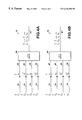
- FIGS. 1A and 1B show the launch polarities of optical signals having adjacent wavelengths, in accordance with a first and second embodiment, respectively, of the present invention.
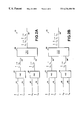
- FIGS. 2A and 2B show a first optical system for implementing the first and second embodiments, respectively, of the present invention.
- FIGS. 3A and 3B show a second optical system for implementing the first and second embodiments, respectively, of the present invention.
- FIGS. 4A and 4B show a third optical system for implementing the first and second embodiments, respectively, of the present invention.
- the present invention includes a system and method for launching optical signals having different wavelengths with orthogonal polarities into an optical fiber.
- the present invention reduces Raman cross-talk by launching these optical signals such that any Raman cross-talk that occurs between optical signals having the same polarities will occur only between optical signals having closely spaced wavelengths.
- ⁇ 1 , ⁇ 2 , ⁇ 3 , and ⁇ 4 each of which is separated from each adjacent wavelength by at least a certain amount, ⁇ .
- ⁇ may be approximately 2-nm.
- optical signals are launched by a transmitter into an optical fiber.
- the polarities of each of the launched optical signals is random, but there is a high probability of all polarizations being aligned and a low probability of all polarizations being orthogonal to each other.
- the polarizations of optical signals launched into an optical fiber are typically described with reference to the principal states of polarization (PSP) axes of an optical fiber, i.e., a fast (vertical) state of polarization and a slow (horizontal) state of polarization, which are orthogonal to each other.
- PPS principal states of polarization
- optical signals will be referred to as having either vertical or horizontal polarizations.
- the present invention launches optical signals with orthogonal polarizations.
- the method of the present invention should reduce Raman cross-talk in fiber optic transport systems by 6 dB.
- any reference to a wavelength ⁇ should be interpreted as a reference to an optical signal that has a wavelength of ⁇ . Therefore, optical signals are identified and referred to herein by their respective wavelengths, ⁇ .
- optical signals having wavelengths ⁇ 1 , ⁇ 2 , ⁇ 3 , and ⁇ 4 are launched into an optical fiber by an optical transmitter at the headend.
- ⁇ 1 has a vertical polarization, as designated by a vertical arrow.
- ⁇ 2 has a horizontal polarization, as designated by a horizontal arrow.
- ⁇ 3 has a vertical polarization, and ⁇ 4 has a horizontal polarization.
- ⁇ 1 and ⁇ 2 have orthogonal polarizations
- ⁇ 3 and ⁇ 4 also have orthogonal polarizations
- ⁇ 1 and ⁇ 4 have orthogonal polarizations
- ⁇ 2 and ⁇ 3 also have orthogonal polarizations.
- Raman cross-talk between ⁇ 1 and ⁇ 2 there will be no Raman cross-talk between ⁇ 1 and ⁇ 2 , between ⁇ 3 and ⁇ 4 , between ⁇ 1 and ⁇ 4 , or between ⁇ 2 and ⁇ 3 .
- Raman cross-talk between ⁇ 1 and ⁇ 3 because both are vertically polarized.
- ⁇ 2 and ⁇ 4 because both are horizontally polarized.
- the amount of Raman cross-talk is dependent, in part, on the wavelength difference between optical signals having the same polarity.
- the wavelength difference between vertically polarized signals ⁇ 1 and ⁇ 3 is 2 ⁇ , because the difference between ⁇ 1 and ⁇ 2 is ⁇ , and the difference between ⁇ 2 and ⁇ 3 is also ⁇ . Therefore, the amount of Raman cross-talk between ⁇ 1 and ⁇ 3 , and similarly between ⁇ 2 and ⁇ 4 , will be based in part on the difference between their wavelengths, 2 ⁇ .
- this Raman cross-talk effect is substantially less than the amount of Raman cross-talk that would occur if the polarizations of each optical signal ⁇ 1 - ⁇ 4 was the same.
- FIG. 1 B A second embodiment of the present invention will now be described with reference to FIG. 1 B.
- the same four optical signals ⁇ 1 , ⁇ 2 , ⁇ 3 , and ⁇ 4 are provided, with ⁇ 1 and ⁇ 2 having vertical polarizations and ⁇ 3 and ⁇ 4 having horizontal polarizations. Therefore, ⁇ 1 and ⁇ 3 have orthogonal polarizations, and ⁇ 2 and ⁇ 4 also have orthogonal polarizations. Similarly, ⁇ 1 and ⁇ 4 have orthogonal polarizations, as do ⁇ 2 and ⁇ 3 .
- the amount of Raman cross-talk that remains when the second embodiment of the present invention is implemented is minimized because the difference in wavelengths between vertically polarized signals ⁇ 1 and ⁇ 2 , and also between horizontally polarized signals ⁇ 3 and ⁇ 4 , is only ⁇ , which is the smallest wavelength difference that is permitted between adjacent signals. Therefore, the Raman cross-talk effect between ⁇ 1 and ⁇ 2 , and also between ⁇ 3 and ⁇ 4 , will be minimized even more than as described with reference to FIG. 1A because it is based on the smallest wavelength difference, ⁇ .
- the present invention is not limited to only four optical signals, but may be implemented for any number of optical signals. For example, if eight optical signals ⁇ 1 - ⁇ 8 were launched, then in accordance with the second embodiment of the present invention ⁇ 1 - ⁇ 4 would have vertical polarizations and ⁇ 5 - ⁇ 8 would have horizontal polarizations.
- the first embodiment of the present invention could also be implemented, but an example of such implementation will not be presented here for the sake of brevity. In this manner, Raman cross-talk would not occur between the orthogonally polarized signals, but would occur between each vertically polarized wavelength ⁇ 1 - ⁇ 4 and between each horizontally polarized wavelength ⁇ 5 - ⁇ 8 .
- the wavelengths between which Raman cross-talk would occur i.e., ⁇ 1 - ⁇ 4 and ⁇ 5 - ⁇ 8
- ⁇ 1 - ⁇ 4 and ⁇ 5 - ⁇ 8 are adjacent to each other with the minimum ⁇ spacing between each adjacent wavelength, thereby minimizing the Raman cross-talk effect.
- ⁇ 1 - ⁇ 4 and ⁇ 5 - ⁇ 8 are adjacent to each other with the minimum ⁇ spacing between each adjacent wavelength, thereby minimizing the Raman cross-talk effect.
- FIGS. 2A-4B An example of a first system 10 for implementing the present invention having the optical signals described with reference to FIG. 1A is shown in FIG. 2 A.
- System 10 is preferably embodied in an optical transmitter at the headend.
- Optical signals having wavelengths ⁇ 1 and ⁇ 2 are input to a first polarization beam combiner (PBC) 12 on input optical fibers 14 and 16 , respectively.
- PBC first polarization beam combiner
- Each input fiber 14 and 16 is a polarization maintaining fiber (PMF), which maintains the polarization of the optical signal.
- PMF polarization maintaining fiber
- ⁇ 3 and ⁇ 4 are input to a second polarization beam combiner (PBC) 18 on input optical fibers 20 and 22 , respectively, each of which is a PMF.
- PBC polarization beam combiner
- Each of the signals, ⁇ 1 , ⁇ 2 , ⁇ 3 , and ⁇ 4 has a vertical polarization.
- the vertical and horizontal arrows above each ⁇ in the figures designates the polarization of each signal at particular locations in the system.
- ⁇ 1 and ⁇ 2 are combined by PBC 12 and are output on fiber 24 , which is also a PMF.
- the PBC 12 outputs ⁇ 1 as a vertically polarized optical signal, but converts ⁇ 2 to a horizontally polarized signal.
- ⁇ 3 and ⁇ 4 are combined by PBC 18 and are output on PMF fiber 26 .
- PBC 18 outputs ⁇ 3 as vertically polarized, and outputs ⁇ 4 as horizontally polarized.
- the signals on fibers 24 and 26 are then input to a dense wavelength division multiplexer (DWDM) 28 , which combines and launches the signals into fiber 30 , which is a single mode fiber (SMF).
- DWDM dense wavelength division multiplexer
- SMF single mode fiber
- An optical coupler can be used instead of the DWDM 28 ; however, the DWDM is preferable because it has less insertion loss than an optical coupler.
- Single mode fiber such as fiber 30 does not maintain the polarization of the signals.
- SMF Single mode fiber
- signals having orthogonal polarizations relative to one another will be maintained orthogonal to one another during transport in the single mode fiber, even though the actual polarization of each signal may change in the SMF.
- the effect of Raman cross-talk typically occurs within the first 20 kilometers (km) of the fiber 30 , but by launching wavelengths into the SMF orthogonal to one another in accordance with the present invention, the effect is minimized.
- the same system, shown in FIG. 2B, can also implement the second embodiment of the present invention having the optical signals described with reference to FIG. 1 B.
- different wavelengths are provided on the input fibers 16 and 20 as compared to the system of FIG. 2 A.
- ⁇ 1 is provided on input fiber 14
- ⁇ 3 is provided on input fiber 16
- ⁇ 2 is provided on input fiber 20
- ⁇ 4 is provided on input fiber 22 .
- ⁇ 1 is vertically polarized and ⁇ 3 is horizontally polarized.
- ⁇ 2 is vertically polarized and ⁇ 4 is horizontally polarized.
- FIGS. 3A and 3B A second example of a system for implementing the present invention is shown in FIGS. 3A and 3B, respectively.
- the PBC is utilized after the optical signals have been combined by wavelength division multiplexers.
- the system 40 preferably embodied in an optical transmitter at the headend, implements the first embodiment of the present invention having the optical signals shown in FIG. 1 A.
- ⁇ 1 is input to WDM 42 on input fiber 44
- ⁇ 3 is input to WDM 42 on input fiber 46
- ⁇ 2 is input to a wavelength division multiplexer (WDM) 48 on input fiber 50
- ⁇ 4 is input to WDM 48 on input fiber 52 .
- Each input fiber 44 , 46 , 50 , and 52 is a PMF and each of wavelengths ⁇ 1 - ⁇ 4 on such fibers is vertically polarized.
- WDM 42 combines ⁇ 1 and ⁇ 3 and outputs both wavelengths on PMF fiber 54 .
- Each wavelength ⁇ 1 and ⁇ 3 output on PMF fiber 54 remains vertically polarized.
- WDM 48 combines ⁇ 2 and ⁇ 4 and outputs the signals on PMF fiber 56 .
- Each wavelength ⁇ 2 and ⁇ 4 on PMF fiber 56 also remains vertically polarized.
- Each wavelength on fibers 54 and 56 are input to PBC coupler 58 , which combines and launches each signal into fiber 30 .
- PBC coupler 58 When output from PBC 58 , both ⁇ 1 and ⁇ 3 remain vertically polarized and ⁇ 2 and ⁇ 4 are changed by the PBC to a horizontally polarization.
- there will be a Raman cross-talk effect between ⁇ 1 and ⁇ 3 , and between ⁇ 2 and ⁇ 4 each of which is separated by 2 ⁇ .
- FIG. 3B The same system, shown in FIG. 3B, can also be used to implement the second embodiment of the present invention having the optical signals described with reference to FIG. 1 B.
- ⁇ 1 is input on fiber 44
- ⁇ 2 is input on fiber 46
- ⁇ 3 is input on fiber 50
- ⁇ 4 is input on fiber 52 .
- ⁇ 1 and ⁇ 2 will be vertically polarized
- ⁇ 3 and ⁇ 4 will be horizontally polarized. This will cause a Raman cross-talk effect between ⁇ 1 and ⁇ 2 , and between ⁇ 3 and ⁇ 4 , each of which is separated by only ⁇ .
- FIGS. 4A and 4B A third example of a system for implementing the present invention as described with reference to FIGS. 1A and 1B is shown in FIGS. 4A and 4B, respectively.
- the system 70 shown in FIGS. 4A and 4B, is preferably embodied in an optical transmitter at the headend.
- System 70 does not include a PBC, as do the systems shown in FIGS. 2A-B and FIGS. 3A-B.
- ⁇ 1 , ⁇ 2 , ⁇ 3 , and ⁇ 4 are input on fibers 72 , 74 , 76 , and 78 , respectively.
- Fibers 74 and 78 are orthogonally spliced to fibers 84 and 88 , respectively.
- Orthogonal splicing uses polarization maintaining splices and changes the polarization of the optical signal on the fiber, such as from vertical polarization to horizontal polarization.
- Fibers 72 and 76 are spliced to fibers 82 and 86 , respectively; however, these splices are not orthogonal splices.
- Each fiber 82 , 84 , 86 , and 88 are PMFs.
- the signals on fibers 82 , 84 , 86 , and 88 are then input to a DWDM 90 or, alternatively, to an optical coupler.
- ⁇ 1 is vertically polarized
- ⁇ 2 is horizontally polarized
- ⁇ 3 is vertically polarized
- ⁇ 4 is horizontally polarized.
- the DWDM 90 combines the signals and launches each of them into fiber 92 with each wavelength having the same polarization as when input to the DWDM. Therefore, there is Raman cross-talk effect between ⁇ 1 and ⁇ 3 , and also between ⁇ 2 and ⁇ 4 , each of which are separated by 2 ⁇ .
- fibers 72 and 74 are spliced, but not orthogonally spliced, to fibers 82 and 84 , respectively.
- Fibers 76 and 78 are orthogonally spliced to fibers 86 and 88 , respectively. It will be understood that this causes ⁇ 1 and ⁇ 2 to be launched with vertical polarizations, and causes ⁇ 3 and ⁇ 4 to be launched with horizontal polarizations. Therefore, there is Raman cross-talk effect between ⁇ 1 and ⁇ 2 , and also between ⁇ 3 and ⁇ 4 . This Raman cross-talk effect is minimized because it occurs between wavelengths that are separated only by ⁇ .
Abstract
Description
Claims (13)
Priority Applications (1)
| Application Number | Priority Date | Filing Date | Title |
|---|---|---|---|
| US09/098,674 US6236480B1 (en) | 1998-05-01 | 1998-06-17 | System and method for reducing Raman cross-talk in a DWDM transport system |
Applications Claiming Priority (2)
| Application Number | Priority Date | Filing Date | Title |
|---|---|---|---|
| US8395498P | 1998-05-01 | 1998-05-01 | |
| US09/098,674 US6236480B1 (en) | 1998-05-01 | 1998-06-17 | System and method for reducing Raman cross-talk in a DWDM transport system |
Publications (1)
| Publication Number | Publication Date |
|---|---|
| US6236480B1 true US6236480B1 (en) | 2001-05-22 |
Family
ID=26769952
Family Applications (1)
| Application Number | Title | Priority Date | Filing Date |
|---|---|---|---|
| US09/098,674 Expired - Fee Related US6236480B1 (en) | 1998-05-01 | 1998-06-17 | System and method for reducing Raman cross-talk in a DWDM transport system |
Country Status (1)
| Country | Link |
|---|---|
| US (1) | US6236480B1 (en) |
Cited By (17)
| Publication number | Priority date | Publication date | Assignee | Title |
|---|---|---|---|---|
| US20020097469A1 (en) * | 1999-12-29 | 2002-07-25 | Yee Ting K. | Optical communications using multiplexed single sideband transmission and heterodyne detection |
| US20020186428A1 (en) * | 2001-06-08 | 2002-12-12 | Saleheen Hasan I. | Crosstalk path enumeration in optical networks |
| US20030137927A1 (en) * | 2002-01-16 | 2003-07-24 | Nec Corporation | Orthogonal polarization multiplexing transmission apparatus and multiplexing method used for the same |
| EP1341334A1 (en) * | 2002-02-28 | 2003-09-03 | Corvis Algety | Polarization alternating transmission systems, apparatuses, and methods |
| EP1345347A2 (en) * | 2002-03-15 | 2003-09-17 | KDDI Submarine Cable Systems Inc. | Optical transmission system, optical transmitter and methods thereof |
| US20050111849A1 (en) * | 2002-02-28 | 2005-05-26 | Corvis France R Et D | Polarization alternating transmission systems, apparatuses, and methods |
| US6904240B1 (en) * | 2000-05-22 | 2005-06-07 | Fujitsu Limited | Optical multiplexing apparatus and optical multiplexing method |
| US20060291868A1 (en) * | 1999-12-29 | 2006-12-28 | Forster Energy Llc | Optical communications using multiplexed single sideband transmission and heterodyne detection |
| US7209660B1 (en) | 1999-12-29 | 2007-04-24 | Forster Energy Llc | Optical communications using heterodyne detection |
| US20070242958A1 (en) * | 2005-02-07 | 2007-10-18 | Tomoaki Ieda | Optical Space Transmitter and Optical Space Transmission Method for Wavelength-Multiplexed Light |
| US20120189306A1 (en) * | 2011-01-21 | 2012-07-26 | Finisar Corporation | Multi-laser transmitter optical subassemblies for optoelectronic modules |
| US20120257899A1 (en) * | 2011-04-06 | 2012-10-11 | Tyco Electronics Subsea Communications Llc | Orthogonal band launch for repeaterless systems |
| US20140079395A1 (en) * | 2012-04-13 | 2014-03-20 | Futurewei Technologies, Inc. | Raman Crosstalk Mitigation in a Multi-Wavelength System Utilizing an Optical Equalizing Signal Modulated with Composite Bandwidth-Limited Data Sources |
| US20150288451A1 (en) * | 2014-04-03 | 2015-10-08 | Commscope, Inc. Of North Carolina | Methods and systems for reducing optical beat interference via polarization diversity in fttx networks |
| CN106685532A (en) * | 2016-12-23 | 2017-05-17 | 武汉邮电科学研究院 | Multi-wavelength optical transmission chip and method utilizing polarization multiplexing function |
| WO2022152115A1 (en) * | 2021-01-14 | 2022-07-21 | 华为技术有限公司 | Device and method for generating dummy light signal, and reconfigurable optical add-drop multiplexer |
| US11924593B1 (en) * | 2023-05-16 | 2024-03-05 | Newphotonics Ltd | Method and system for co-packaged optics |
Citations (8)
| Publication number | Priority date | Publication date | Assignee | Title |
|---|---|---|---|---|
| US5589969A (en) * | 1995-03-15 | 1996-12-31 | Kokusai Denshin Denwa Kabushiki Kaisha | Wavelength division multiplexed optical fiber transmission equipment |
| US5696614A (en) * | 1993-08-10 | 1997-12-09 | Fujitsu Limited | Optical wavelength multiplex transmission method and optical dispersion compensation method |
| US5841557A (en) * | 1995-11-17 | 1998-11-24 | Fujitsu Limited | Method and apparatus for scrambling the polarization of signal lights forming a wavelength division multiplexed signal light |
| US5912910A (en) * | 1996-05-17 | 1999-06-15 | Sdl, Inc. | High power pumped mid-IR wavelength systems using nonlinear frequency mixing (NFM) devices |
| US5946116A (en) * | 1997-04-02 | 1999-08-31 | Wu; Kuang-Yi | 1 X N digitally programmable optical routing switch |
| US5995256A (en) * | 1997-09-30 | 1999-11-30 | Mci Communications Corporation | Method and system for managing optical subcarrier reception |
| US6005697A (en) * | 1996-07-23 | 1999-12-21 | Macro-Vision Communications, L.L.C. | Multi-wavelength cross-connect optical network |
| US6041152A (en) * | 1997-09-02 | 2000-03-21 | Amphenol Corporation | Multi-channel fiber optic communications system and multiplexer/demultiplexer arrangement therefor |
-
1998
- 1998-06-17 US US09/098,674 patent/US6236480B1/en not_active Expired - Fee Related
Patent Citations (8)
| Publication number | Priority date | Publication date | Assignee | Title |
|---|---|---|---|---|
| US5696614A (en) * | 1993-08-10 | 1997-12-09 | Fujitsu Limited | Optical wavelength multiplex transmission method and optical dispersion compensation method |
| US5589969A (en) * | 1995-03-15 | 1996-12-31 | Kokusai Denshin Denwa Kabushiki Kaisha | Wavelength division multiplexed optical fiber transmission equipment |
| US5841557A (en) * | 1995-11-17 | 1998-11-24 | Fujitsu Limited | Method and apparatus for scrambling the polarization of signal lights forming a wavelength division multiplexed signal light |
| US5912910A (en) * | 1996-05-17 | 1999-06-15 | Sdl, Inc. | High power pumped mid-IR wavelength systems using nonlinear frequency mixing (NFM) devices |
| US6005697A (en) * | 1996-07-23 | 1999-12-21 | Macro-Vision Communications, L.L.C. | Multi-wavelength cross-connect optical network |
| US5946116A (en) * | 1997-04-02 | 1999-08-31 | Wu; Kuang-Yi | 1 X N digitally programmable optical routing switch |
| US6041152A (en) * | 1997-09-02 | 2000-03-21 | Amphenol Corporation | Multi-channel fiber optic communications system and multiplexer/demultiplexer arrangement therefor |
| US5995256A (en) * | 1997-09-30 | 1999-11-30 | Mci Communications Corporation | Method and system for managing optical subcarrier reception |
Cited By (29)
| Publication number | Priority date | Publication date | Assignee | Title |
|---|---|---|---|---|
| US7447436B2 (en) | 1999-12-29 | 2008-11-04 | Forster Energy Llc | Optical communications using multiplexed single sideband transmission and heterodyne detection |
| US20070133993A1 (en) * | 1999-12-29 | 2007-06-14 | Forster Energy Llc | Optical communications using multiplexed single sideband transmission and heterodyne detection |
| US7209660B1 (en) | 1999-12-29 | 2007-04-24 | Forster Energy Llc | Optical communications using heterodyne detection |
| US20060291868A1 (en) * | 1999-12-29 | 2006-12-28 | Forster Energy Llc | Optical communications using multiplexed single sideband transmission and heterodyne detection |
| US7146103B2 (en) * | 1999-12-29 | 2006-12-05 | Forster Energy Llc | Optical communications using multiplexed single sideband transmission and heterodyne detection |
| US20020097469A1 (en) * | 1999-12-29 | 2002-07-25 | Yee Ting K. | Optical communications using multiplexed single sideband transmission and heterodyne detection |
| US6904240B1 (en) * | 2000-05-22 | 2005-06-07 | Fujitsu Limited | Optical multiplexing apparatus and optical multiplexing method |
| US20020186428A1 (en) * | 2001-06-08 | 2002-12-12 | Saleheen Hasan I. | Crosstalk path enumeration in optical networks |
| GB2384930B (en) * | 2002-01-16 | 2004-04-14 | Nec Corp | Orthogonal polarization multiplexing transmission apparatus and multiplexing method used for the same |
| GB2384930A (en) * | 2002-01-16 | 2003-08-06 | Nec Corp | Orthogonal polarization multiplexing |
| US7366209B2 (en) * | 2002-01-16 | 2008-04-29 | Nec Corporation | Orthogonal polarization multiplexing transmission apparatus and multiplexing method used for the same |
| US20030137927A1 (en) * | 2002-01-16 | 2003-07-24 | Nec Corporation | Orthogonal polarization multiplexing transmission apparatus and multiplexing method used for the same |
| US20050111849A1 (en) * | 2002-02-28 | 2005-05-26 | Corvis France R Et D | Polarization alternating transmission systems, apparatuses, and methods |
| WO2003073672A1 (en) * | 2002-02-28 | 2003-09-04 | Corvis France R Et D | Polarization alternating trasmission systems, apparatuses, and methods |
| EP1341334A1 (en) * | 2002-02-28 | 2003-09-03 | Corvis Algety | Polarization alternating transmission systems, apparatuses, and methods |
| EP1345347A3 (en) * | 2002-03-15 | 2004-07-14 | KDDI Submarine Cable Systems Inc. | Optical transmission system, optical transmitter and methods thereof |
| EP1345347A2 (en) * | 2002-03-15 | 2003-09-17 | KDDI Submarine Cable Systems Inc. | Optical transmission system, optical transmitter and methods thereof |
| US20070242958A1 (en) * | 2005-02-07 | 2007-10-18 | Tomoaki Ieda | Optical Space Transmitter and Optical Space Transmission Method for Wavelength-Multiplexed Light |
| US8064772B2 (en) * | 2005-02-07 | 2011-11-22 | Panasonic Corporation | Optical space transmitter and optical space transmission method for wavelength-multiplexed light |
| US20120189306A1 (en) * | 2011-01-21 | 2012-07-26 | Finisar Corporation | Multi-laser transmitter optical subassemblies for optoelectronic modules |
| US8625989B2 (en) * | 2011-01-21 | 2014-01-07 | Finisar Corporation | Multi-laser transmitter optical subassemblies for optoelectronic modules |
| US20120257899A1 (en) * | 2011-04-06 | 2012-10-11 | Tyco Electronics Subsea Communications Llc | Orthogonal band launch for repeaterless systems |
| US20140079395A1 (en) * | 2012-04-13 | 2014-03-20 | Futurewei Technologies, Inc. | Raman Crosstalk Mitigation in a Multi-Wavelength System Utilizing an Optical Equalizing Signal Modulated with Composite Bandwidth-Limited Data Sources |
| US9118388B2 (en) * | 2012-04-13 | 2015-08-25 | Futurewei Technologies, Inc. | Raman crosstalk mitigation in a multi-wavelength system utilizing an optical equalizing signal modulated with composite bandwidth-limited data sources |
| US20150288451A1 (en) * | 2014-04-03 | 2015-10-08 | Commscope, Inc. Of North Carolina | Methods and systems for reducing optical beat interference via polarization diversity in fttx networks |
| US9705598B2 (en) * | 2014-04-03 | 2017-07-11 | Commscope, Inc. Of North Carolina | Methods and systems for reducing optical beat interference via polarization diversity in FTTx networks |
| CN106685532A (en) * | 2016-12-23 | 2017-05-17 | 武汉邮电科学研究院 | Multi-wavelength optical transmission chip and method utilizing polarization multiplexing function |
| WO2022152115A1 (en) * | 2021-01-14 | 2022-07-21 | 华为技术有限公司 | Device and method for generating dummy light signal, and reconfigurable optical add-drop multiplexer |
| US11924593B1 (en) * | 2023-05-16 | 2024-03-05 | Newphotonics Ltd | Method and system for co-packaged optics |
Similar Documents
| Publication | Publication Date | Title |
|---|---|---|
| US6236480B1 (en) | System and method for reducing Raman cross-talk in a DWDM transport system | |
| US6151145A (en) | Two-wavelength WDM Analog CATV transmission with low crosstalk | |
| EP0763908B1 (en) | Optical network using multiple Erbium Doped Fibre Amplifiers with a Common Supply | |
| Chraplyvy et al. | 1-Tb/s transmission experiment | |
| Huang et al. | WDM free-space optical communication system of high-speed hybrid signals | |
| US20080038000A1 (en) | Monitoring and in-line compensation of polarization dependent loss for lightwave systems | |
| SK93895A3 (en) | Optical telecomunicating system | |
| Rademacher et al. | High capacity transmission in a coupled-core three-core multi-core fiber | |
| JPH06258545A (en) | Optical branching device | |
| SK158295A3 (en) | Wavelenght-division multiplexing telecommunication system with dispersion-shifted optical fibers | |
| KR100324797B1 (en) | Wavelength-division-multiplexed free-space optical communication systems | |
| CN110521142A (en) | Two-way optical transmission system and bi-directional light transmissions pass method | |
| US8391723B2 (en) | Ramen backpumped near-zero dispersion CWDM system and method | |
| Ho et al. | Hybrid wavelength-division-multiplexing systems for high-capacity digital and analog video trunking applications | |
| US20040028319A1 (en) | Optical communication system and method | |
| Yoneda et al. | Erbium-doped fiber amplifier for video distribution networks | |
| US6674557B1 (en) | Wavelength division multiplexing systems | |
| Taga et al. | 459km, 2.4 Gbit/s 4 wavelength multiplexing optical fiber transmission experiment using 6 Er-doped fiber amplifiers | |
| Lu | Performance comparison between DCF and RDF dispersion compensation in fiber optical CATV systems | |
| US6411413B1 (en) | Method and apparatus for performing dispersion compensation without a change in polarization and a transmitter incorporating same | |
| Birk et al. | Field trial of end-to-end OC-768 transmission using 9 WDM channels over 1000km of installed fiber | |
| Chen et al. | Directly modulated 1.55 µm AM-VSB video EDFA-repeatered supertrunking system over 110 km standard singlemode fibre using split-band and wavelength division multiplexing techniques | |
| CA2478357A1 (en) | Method and apparatus to reduce second order distortion in optical communications | |
| Kuo et al. | High-performance optically amplified 1550-nm lightwave AM-VSB CATV transport system | |
| JP3566396B2 (en) | Optical transmission equipment |
Legal Events
| Date | Code | Title | Description |
|---|---|---|---|
| AS | Assignment |
Owner name: ANTEC CORPORATION, GEORGIA Free format text: ASSIGNMENT OF ASSIGNORS INTEREST;ASSIGNOR:ATLAS, DOGAN A.;REEL/FRAME:009254/0997 Effective date: 19980616 |
|
| AS | Assignment |
Owner name: CIT GROUP BUSINESS/CREDIT, INC., THE, GEORGIA Free format text: GRANT OF PATENT SECURITY INTEREST;ASSIGNOR:ARRIS INTERNATIONAL, INC.;REEL/FRAME:012059/0793 Effective date: 20010803 |
|
| AS | Assignment |
Owner name: CIT GROUP BUSINESS/CREDIT, INC., THE, GEORGIA Free format text: GRANT OF PATENT SECURITY INTEREST;ASSIGNOR:ARRIS INTERNATIONAL, INC., (F/K/A ANTEC CORPORATION);REEL/FRAME:012322/0056 Effective date: 20010803 |
|
| AS | Assignment |
Owner name: ARRIS INTERNATIONAL, INC., GEORGIA Free format text: RELEASE OF SECURITY INTEREST IN PATENTS;ASSIGNOR:CIT GROUP/BUSINESS CREDIT, INC., THE;REEL/FRAME:014491/0701 Effective date: 20040202 |
|
| FEPP | Fee payment procedure |
Free format text: PETITION RELATED TO MAINTENANCE FEES FILED (ORIGINAL EVENT CODE: PMFP); ENTITY STATUS OF PATENT OWNER: LARGE ENTITY |
|
| FEPP | Fee payment procedure |
Free format text: PETITION RELATED TO MAINTENANCE FEES GRANTED (ORIGINAL EVENT CODE: PMFG); ENTITY STATUS OF PATENT OWNER: LARGE ENTITY |
|
| REMI | Maintenance fee reminder mailed | ||
| REIN | Reinstatement after maintenance fee payment confirmed | ||
| FP | Lapsed due to failure to pay maintenance fee |
Effective date: 20050522 |
|
| PRDP | Patent reinstated due to the acceptance of a late maintenance fee |
Effective date: 20050826 |
|
| REMI | Maintenance fee reminder mailed | ||
| LAPS | Lapse for failure to pay maintenance fees | ||
| STCH | Information on status: patent discontinuation |
Free format text: PATENT EXPIRED DUE TO NONPAYMENT OF MAINTENANCE FEES UNDER 37 CFR 1.362 |
|
| FP | Lapsed due to failure to pay maintenance fee |
Effective date: 20090522 |