US6252976B1 - Computer program product for redeye detection - Google Patents
Computer program product for redeye detection Download PDFInfo
- Publication number
- US6252976B1 US6252976B1 US09/084,774 US8477498A US6252976B1 US 6252976 B1 US6252976 B1 US 6252976B1 US 8477498 A US8477498 A US 8477498A US 6252976 B1 US6252976 B1 US 6252976B1
- Authority
- US
- United States
- Prior art keywords
- redeye
- defects
- image
- pair
- candidate
- Prior art date
- Legal status (The legal status is an assumption and is not a legal conclusion. Google has not performed a legal analysis and makes no representation as to the accuracy of the status listed.)
- Expired - Lifetime
Links
Images


Classifications
-
- G—PHYSICS
- G06—COMPUTING; CALCULATING OR COUNTING
- G06V—IMAGE OR VIDEO RECOGNITION OR UNDERSTANDING
- G06V40/00—Recognition of biometric, human-related or animal-related patterns in image or video data
- G06V40/10—Human or animal bodies, e.g. vehicle occupants or pedestrians; Body parts, e.g. hands
- G06V40/18—Eye characteristics, e.g. of the iris
- G06V40/193—Preprocessing; Feature extraction
-
- G—PHYSICS
- G06—COMPUTING; CALCULATING OR COUNTING
- G06T—IMAGE DATA PROCESSING OR GENERATION, IN GENERAL
- G06T7/00—Image analysis
- G06T7/0002—Inspection of images, e.g. flaw detection
-
- G—PHYSICS
- G06—COMPUTING; CALCULATING OR COUNTING
- G06T—IMAGE DATA PROCESSING OR GENERATION, IN GENERAL
- G06T7/00—Image analysis
- G06T7/90—Determination of colour characteristics
-
- H—ELECTRICITY
- H04—ELECTRIC COMMUNICATION TECHNIQUE
- H04N—PICTORIAL COMMUNICATION, e.g. TELEVISION
- H04N1/00—Scanning, transmission or reproduction of documents or the like, e.g. facsimile transmission; Details thereof
- H04N1/46—Colour picture communication systems
- H04N1/56—Processing of colour picture signals
- H04N1/60—Colour correction or control
- H04N1/62—Retouching, i.e. modification of isolated colours only or in isolated picture areas only
- H04N1/624—Red-eye correction
-
- G—PHYSICS
- G06—COMPUTING; CALCULATING OR COUNTING
- G06T—IMAGE DATA PROCESSING OR GENERATION, IN GENERAL
- G06T2207/00—Indexing scheme for image analysis or image enhancement
- G06T2207/10—Image acquisition modality
- G06T2207/10024—Color image
-
- G—PHYSICS
- G06—COMPUTING; CALCULATING OR COUNTING
- G06T—IMAGE DATA PROCESSING OR GENERATION, IN GENERAL
- G06T2207/00—Indexing scheme for image analysis or image enhancement
- G06T2207/30—Subject of image; Context of image processing
- G06T2207/30196—Human being; Person
- G06T2207/30201—Face
-
- G—PHYSICS
- G06—COMPUTING; CALCULATING OR COUNTING
- G06T—IMAGE DATA PROCESSING OR GENERATION, IN GENERAL
- G06T2207/00—Indexing scheme for image analysis or image enhancement
- G06T2207/30—Subject of image; Context of image processing
- G06T2207/30216—Redeye defect
Definitions
- FIG. 9 is a detailed flowchart of the candidate redeye determination portion of FIG. 2;
- a color digital image is input to the software program residing on a computer system, such computer systems being well known in the art.
- the code values of the digital image are preferably proportional to the log of the amount of exposure of the film used to capture the image by the original scene S 2 .
- the program begins by identifying all separate continuous skin colored regions in the image S 4 .
- step S 4 there is illustrated a detail flowchart of step S 4 in FIG. 2 .
- the next step is to build a three-dimensional histogram.
- the L, S, and T code values are quantized by dividing them by 8.0 ⁇ sqrt( 3 ), 2.0, and 2.0, respectively S 4 b. These quantized code values are referred to as L′, S′, and T′.
- Each combination of L′, S′, and T′ values is referred to as a “bin” of the histogram.
- the value of the histogram H(L′, S′, T′) S 4 c is equal to the number of pixels in the image that have quantized code values of L′, S′, and T′.
- An alternative way of stating this is that the histogram tell us the number of pixels in the image that fall into each bin. This number is referred to as the value of the bin.
- a unique number is assigned to all such regions in the segmented image S 4 h.
- the numbers are sequentially assigned starting with 1 for the region with the greatest number of pixels.
- the single band image in which code values correspond to the label of the region that the pixel belongs to is called the labeled image.
- One final step is necessary to associate each face in the color image with a single skin colored region.
- the process described above will often result in a single face being associated with more that one skin colored region because due to complexion, shadows, and etc., the color of the face is not uniform.
- Two skin colored regions are merged into a single skin colored region if two conditions are satisfied S 4 k.
- the first condition requires that the two regions be inter-connected.
- a pixel in region i has a connection to region j if a pixel belonging to region j is one of the eight nearest neighbor pixels.
- a function Q(i, j) is calculated which is proportional to the number of connections between pixels of region i and j. The function is normalized so that Q(i, i) is equal to 1.0.
- MaxMergeColorDistance which is set equal to 40.0.
- the process of merging skin colored regions begins with the smallest region which, if the two conditions are satisfied, is merged with a larger region. If region i is merged with larger region j it may then happen that region j gets merged with an even larger region k. When this occurs regions i,j, and k are merged into a single region. Note that regions i and k may be merged together even though the above two conditions are not satisfied for these two regions. They are merged because of their mutual connection to region j.
- the sub-color-images 40 are processed so as to identify small red features.
- the program begins by defining a new single band image S 16 a with pixel values X given by
- the result of the above processing is a map of candidate redeye pixels for each sub-color-image S 16 k.
- the ellipses in FIG. 8 are approximate maps of the region in the corresponding sub-color-images in FIG. 7 that have been identified as potentially being a face. Therefore, only the candidate redeye pixels that fall inside of the ellipse are considered in the next phase eye detection which is outlined in FIG. 11 .
- the purpose of eye detection is to determine whether the candidate redeye pixels are indeed part of an eye.
- the eye detection procedure requires a monotone version of the color image S 18 .
- the eye detection procedure S 20 in FIG. 2 is based on the process of template matching. It facilitates understanding to note that any image of an eye can be used a the template.
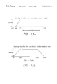
- the top image 60 in FIG. 12 shows a left-eye template.
- the bottom image 70 shows a division of the template into zones. Zone 1 is the eyebrow region. Zones 2 and 3 are the left and right sides of the eye, respectively. Zone 4 includes the pupil and iris. Zone 0 is not used.
- the estimation of the face width from the minor axis of the ellipse will not always be accurate. Also, the eyes may be tilted. For this reason starting with the original left-eye template and the zone map, a collection of left-eye, right-eye (mirror image of left-eye), and zone maps are generated that span a range of sizes and orientations S 22 .
- the original eye template and zone map are resized from a factor of S 0 ⁇ Narrow to S 0 ⁇ Wide in increments of SStep.
- Preferred values of Narrow, Wide, and Sstep are 1.5, 0.50, and 0.05, respectively.
- an ensemble of eye templates and zone map templates were made that span a range of resize factors from S 0 ⁇ Narrow to S 0 ⁇ Wide with resolution SStep and with a tilt from ⁇ MaxTilt degrees to MaxTilt degrees with a resolution TStep.
- the left-eye template, right-eye template, and zone map that most closely match the value of S pair and Tilt for the pair of candidate redeye pixels is used in the correlation step that follows. If S pair or Tilt are outside of this range, this pair is not processed further S 20 c.
- the color of the candidate redeye pixel must be indicative of a real redeye defect.
- code values of the candidate redeye pixel is convert into luminance (Lum), hue (Hue), and saturation (Sat) values.
- step S 24 b it is determined if the peak pixel is part of the skin colored region of the image. If this pixel is part of the skin colored region, the program proceeds to the next peak. If the peak pixel is not in the skin colored region, the program proceeds to the next step S 24 c.
- a redeye defect must occur in the region of a face. Usually it will occur within a hole in the skin map of the face. However, if the face is in a slight profile position with respect to the camera that captured the image, the redeye defect may occur outside of the skin map.
- the map of skin colored regions is fitted to an ellipse. This ellipse is referred to as the ellipse of best fit. It is possible for a redeye defect that is associated with a face to fall outside the ellipse of best fit due to the face being in a profile position. For this reason, an expanded ellipse is defined that has the same center and shape as the ellipse of best fit, but a greater radius. Typically the radius will be twice as large. A peak pixel must fall inside of the extended ellipse for it to be considered further. This is shown in step S 24 c of FIG. 14 .
- a total score can now be assigned S 24 n to the candidate redeye defect based on a combination of all of the above scores. Typically, this score is the product of the individual scores although the use of the sum or median value is also contemplated.
- the candidate redeye defects can now be assigned a ranked order based on this score.
- redeye defect may vary considerably from image to image mainly because of color balance differences. Also, redeye defect color variations occur among people. However, when two redeye defects occur in a face their color should be consistent with each other.
- the program assigns a score to the candidate redeye defect pair based on the consistency of their color. In general, the score decreases as the value of C increases.
- the tilt of the candidate redeye pair with respect to a horizontal line in the image is less that MaxTilt. In this case (see step S 30 i in FIG. 17) the pair of candidate redeye pixels is processed further. Otherwise, the next pair is considered.
- step S 30 k a score is assigned base on the consistency of the standard deviation of the luminance in the region around the left and right candidate redeye defects. As described hereinabove on page 23, line 6 through page 15 line 21, this standard deviation is calculated in the process of calculating the correlation.
- the candidate redeye defect pair with the highest score is processed further.
- the mirror symmetry of the region of the image in the vicinity of the pair about a line that bisects a line that connects the candidate redeye defects is calculated. This is discussed in detail starting on line 16 on page 21.
- a score is assigned to the pair based to symmetry.
Abstract
Description


Claims (13)
Priority Applications (3)
| Application Number | Priority Date | Filing Date | Title |
|---|---|---|---|
| US09/084,774 US6252976B1 (en) | 1997-08-29 | 1998-05-26 | Computer program product for redeye detection |
| EP99201509A EP0961225A3 (en) | 1998-05-26 | 1999-05-14 | A computer program product for redeye detection |
| JP11145990A JP2000125320A (en) | 1998-05-26 | 1999-05-26 | Computer program product for detecting pink eyes |
Applications Claiming Priority (2)
| Application Number | Priority Date | Filing Date | Title |
|---|---|---|---|
| US08/919,560 US6292574B1 (en) | 1997-08-29 | 1997-08-29 | Computer program product for redeye detection |
| US09/084,774 US6252976B1 (en) | 1997-08-29 | 1998-05-26 | Computer program product for redeye detection |
Related Parent Applications (1)
| Application Number | Title | Priority Date | Filing Date |
|---|---|---|---|
| US08/919,560 Continuation-In-Part US6292574B1 (en) | 1997-08-29 | 1997-08-29 | Computer program product for redeye detection |
Publications (1)
| Publication Number | Publication Date |
|---|---|
| US6252976B1 true US6252976B1 (en) | 2001-06-26 |
Family
ID=22187133
Family Applications (1)
| Application Number | Title | Priority Date | Filing Date |
|---|---|---|---|
| US09/084,774 Expired - Lifetime US6252976B1 (en) | 1997-08-29 | 1998-05-26 | Computer program product for redeye detection |
Country Status (3)
| Country | Link |
|---|---|
| US (1) | US6252976B1 (en) |
| EP (1) | EP0961225A3 (en) |
| JP (1) | JP2000125320A (en) |
Cited By (142)
| Publication number | Priority date | Publication date | Assignee | Title |
|---|---|---|---|---|
| US20020114495A1 (en) * | 2000-12-19 | 2002-08-22 | Eastman Kodak Company | Multi-mode digital image processing method for detecting eyes |
| US20020176623A1 (en) * | 2001-03-29 | 2002-11-28 | Eran Steinberg | Method and apparatus for the automatic real-time detection and correction of red-eye defects in batches of digital images or in handheld appliances |
| US20030021478A1 (en) * | 2001-07-25 | 2003-01-30 | Minolta Co., Ltd. | Image processing technology for identification of red eyes in image |
| US20030044063A1 (en) * | 2001-09-03 | 2003-03-06 | Guenter Meckes | Method for processing digital photographic image data that includes a method for the automatic detection of red-eye defects |
| US20030044177A1 (en) * | 2001-09-03 | 2003-03-06 | Knut Oberhardt | Method for the automatic detection of red-eye defects in photographic image data |
| US20030044070A1 (en) * | 2001-09-03 | 2003-03-06 | Manfred Fuersich | Method for the automatic detection of red-eye defects in photographic image data |
| WO2003026278A1 (en) * | 2001-09-14 | 2003-03-27 | Pixology Limited | Image processing to remove red-eye features |
| US6587801B2 (en) * | 2000-07-24 | 2003-07-01 | Mitsubishi Denki Kabushiki Kaisha | Abnormality-cause identifying apparatus and method |
| US6600830B1 (en) * | 1999-08-04 | 2003-07-29 | Cyberlink Corporation | Method and system of automatically extracting facial features |
| US20030142220A1 (en) * | 1997-07-15 | 2003-07-31 | Kia Silverbrook | Method of image enhancement |
| US20030161506A1 (en) * | 2002-02-25 | 2003-08-28 | Eastman Kodak Company | Face detection computer program product for redeye correction |
| US20030174869A1 (en) * | 2002-03-12 | 2003-09-18 | Suarez Anthony P. | Image processing apparatus, image processing method, program and recording medium |
| US6631208B1 (en) * | 1998-05-29 | 2003-10-07 | Fuji Photo Film Co., Ltd. | Image processing method |
| US20030201996A1 (en) * | 2002-04-30 | 2003-10-30 | Canon Kabushiki Kaisha | Method and apparatus for generating models of individuals |
| US20040012677A1 (en) * | 2002-04-30 | 2004-01-22 | Agfa-Gevaert Aktiengesellschaft | Apparatus and method for processing images |
| US20040032512A1 (en) * | 1997-05-15 | 2004-02-19 | Kia Silverbrook | Correction of distortions in digital images |
| US20040037460A1 (en) * | 2002-08-22 | 2004-02-26 | Eastman Kodak Company | Method for detecting objects in digital images |
| US20040041924A1 (en) * | 2002-08-29 | 2004-03-04 | White Timothy J. | Apparatus and method for processing digital images having eye color defects |
| US20040100518A1 (en) * | 1997-07-15 | 2004-05-27 | Kia Silverbrook | Inkjet printhead with short nozzle |
| US20040197011A1 (en) * | 2003-04-04 | 2004-10-07 | Camus Theodore A. | Method and apparatus for providing a robust object finder |
| US20040196472A1 (en) * | 1997-07-15 | 2004-10-07 | Silverbrook Research Pty Ltd | Media cartridge for inkjet printhead |
| US20040213476A1 (en) * | 2003-04-28 | 2004-10-28 | Huitao Luo | Detecting and correcting red-eye in a digital image |
| US20040228542A1 (en) * | 2003-05-13 | 2004-11-18 | Microsoft Corporation | Modification of red-eye-effect in digital image |
| US20040233299A1 (en) * | 2003-05-19 | 2004-11-25 | Sergey Ioffe | Method and apparatus for red-eye detection |
| US20040257446A1 (en) * | 1997-07-15 | 2004-12-23 | Silverbrook Research Pty Ltd | Image processor for digital camera |
| US20040263675A1 (en) * | 1997-07-15 | 2004-12-30 | Silverbrook Research Pty Ltd | Digital camera using exposure information for image processing |
| US20040263640A1 (en) * | 1997-07-15 | 2004-12-30 | Silverbrook Research Pty Ltd | Image processor for digital camera |
| US20050031224A1 (en) * | 2003-08-05 | 2005-02-10 | Yury Prilutsky | Detecting red eye filter and apparatus using meta-data |
| US20050041121A1 (en) * | 1997-10-09 | 2005-02-24 | Eran Steinberg | Red-eye filter method and apparatus |
| US20050069219A1 (en) * | 2003-09-29 | 2005-03-31 | Shang-Yun Wu | Method of processing red eye in digital images |
| US20050196067A1 (en) * | 2004-03-03 | 2005-09-08 | Eastman Kodak Company | Correction of redeye defects in images of humans |
| US20050220346A1 (en) * | 2004-03-30 | 2005-10-06 | Fuji Photo Film Co., Ltd. | Red eye detection device, red eye detection method, and recording medium with red eye detection program |
| US20050219334A1 (en) * | 1997-07-15 | 2005-10-06 | Silverbrook Research Pty Ltd | Compact media and ink cartridge for inkjet printhead |
| US20050232490A1 (en) * | 2004-03-30 | 2005-10-20 | Fuji Photo Film Co., Ltd. | Red-eye detection device, red-eye detection method, and red-eye detection program |
| US20050238209A1 (en) * | 2004-04-21 | 2005-10-27 | Fuji Xerox Co., Ltd. | Image recognition apparatus, image extraction apparatus, image extraction method, and program |
| US20050271295A1 (en) * | 2004-05-13 | 2005-12-08 | Naohiro Tabata | Image correction apparatus |
| US20050286766A1 (en) * | 2003-09-30 | 2005-12-29 | Ferman A M | Red eye reduction technique |
| US20060008173A1 (en) * | 2004-06-29 | 2006-01-12 | Canon Kabushiki Kaisha | Device and method for correcting image including person area |
| US20060029263A1 (en) * | 2004-08-09 | 2006-02-09 | Yue Zhang | Method, apparatus and storage medium for processing an image |
| EP1626569A1 (en) * | 2004-08-11 | 2006-02-15 | Fuji Photo Film Co., Ltd | Method and apparatus for detecting structural elements of subjects in digital images |
| US20060056687A1 (en) * | 2004-09-15 | 2006-03-16 | Jonathan Brandt | Hierarchically locating a feature in a digital image |
| US20060093212A1 (en) * | 2004-10-28 | 2006-05-04 | Eran Steinberg | Method and apparatus for red-eye detection in an acquired digital image |
| US7042505B1 (en) | 1997-10-09 | 2006-05-09 | Fotonation Ireland Ltd. | Red-eye filter method and apparatus |
| US20060098867A1 (en) * | 2004-11-10 | 2006-05-11 | Eastman Kodak Company | Detecting irises and pupils in images of humans |
| US20060153429A1 (en) * | 2002-10-24 | 2006-07-13 | Stefan Gehlen | Method for controlling photographs of people |
| US20060204054A1 (en) * | 2003-06-26 | 2006-09-14 | Eran Steinberg | Digital image processing composition using face detection information |
| US20060274950A1 (en) * | 2005-06-06 | 2006-12-07 | Xerox Corporation | Red-eye detection and correction |
| US20060280361A1 (en) * | 2005-06-14 | 2006-12-14 | Canon Kabushiki Kaisha | Image processing apparatus, image processing method,computer program, and storage medium |
| US20060280362A1 (en) * | 2005-06-14 | 2006-12-14 | Canon Kabushiki Kaisha | Image processing apparatus, image processing method, computer program, and storage medium |
| US20070031033A1 (en) * | 2005-08-08 | 2007-02-08 | Samsung Electronics Co., Ltd. | Method and apparatus for converting skin color of image |
| US20070116380A1 (en) * | 2005-11-18 | 2007-05-24 | Mihai Ciuc | Method and apparatus of correcting hybrid flash artifacts in digital images |
| US20070140556A1 (en) * | 2005-12-20 | 2007-06-21 | Xerox Corporation | Red eye detection and correction |
| US20070263928A1 (en) * | 2006-05-15 | 2007-11-15 | Fujifilm Corporation | Method, apparatus, and program for processing red eyes |
| US20070274573A1 (en) * | 2006-05-26 | 2007-11-29 | Canon Kabushiki Kaisha | Image processing method and image processing apparatus |
| US20080013800A1 (en) * | 2003-06-26 | 2008-01-17 | Fotonation Vision Limited | Method of Improving Orientation and Color Balance of Digital Images Using Face Detection Information |
| US7352394B1 (en) | 1997-10-09 | 2008-04-01 | Fotonation Vision Limited | Image modification based on red-eye filter analysis |
| US20080095445A1 (en) * | 2004-09-15 | 2008-04-24 | Adobe Systems Incorporated | Locating A Feature In A Digital Image |
| US20080137944A1 (en) * | 2006-12-12 | 2008-06-12 | Luca Marchesotti | Adaptive red eye correction |
| US20080199073A1 (en) * | 2007-02-20 | 2008-08-21 | Microsoft Corporation | Red eye detection in digital images |
| US20080292183A1 (en) * | 1997-10-09 | 2008-11-27 | Fotonation Ireland Limited | Detecting red eye filter and apparatus using meta-data |
| US20080317339A1 (en) * | 2004-10-28 | 2008-12-25 | Fotonation Ireland Limited | Method and apparatus for red-eye detection using preview or other reference images |
| US7565030B2 (en) | 2003-06-26 | 2009-07-21 | Fotonation Vision Limited | Detecting orientation of digital images using face detection information |
| US7574016B2 (en) | 2003-06-26 | 2009-08-11 | Fotonation Vision Limited | Digital image processing using face detection information |
| US20090220148A1 (en) * | 2008-03-03 | 2009-09-03 | Zoran Corporation | Automatic red eye artifact reduction for images |
| US7587085B2 (en) | 2004-10-28 | 2009-09-08 | Fotonation Vision Limited | Method and apparatus for red-eye detection in an acquired digital image |
| US7616233B2 (en) | 2003-06-26 | 2009-11-10 | Fotonation Vision Limited | Perfecting of digital image capture parameters within acquisition devices using face detection |
| US7620218B2 (en) | 2006-08-11 | 2009-11-17 | Fotonation Ireland Limited | Real-time face tracking with reference images |
| US20090324127A1 (en) * | 2008-06-30 | 2009-12-31 | Madhukar Budagavi | Method and System for Automatic Red-Eye Correction |
| US7684630B2 (en) | 2003-06-26 | 2010-03-23 | Fotonation Vision Limited | Digital image adjustable compression and resolution using face detection information |
| US7689009B2 (en) | 2005-11-18 | 2010-03-30 | Fotonation Vision Ltd. | Two stage detection for photographic eye artifacts |
| US7693311B2 (en) | 2003-06-26 | 2010-04-06 | Fotonation Vision Limited | Perfecting the effect of flash within an image acquisition devices using face detection |
| US7844076B2 (en) | 2003-06-26 | 2010-11-30 | Fotonation Vision Limited | Digital image processing using face detection and skin tone information |
| US7855737B2 (en) | 2008-03-26 | 2010-12-21 | Fotonation Ireland Limited | Method of making a digital camera image of a scene including the camera user |
| US7864990B2 (en) | 2006-08-11 | 2011-01-04 | Tessera Technologies Ireland Limited | Real-time face tracking in a digital image acquisition device |
| US20110026051A1 (en) * | 2009-07-31 | 2011-02-03 | Sen Wang | Digital image brightness adjustment using range information |
| US20110026807A1 (en) * | 2009-07-29 | 2011-02-03 | Sen Wang | Adjusting perspective and disparity in stereoscopic image pairs |
| US20110026764A1 (en) * | 2009-07-28 | 2011-02-03 | Sen Wang | Detection of objects using range information |
| US20110038509A1 (en) * | 2009-08-11 | 2011-02-17 | Sen Wang | Determining main objects using range information |
| US20110044530A1 (en) * | 2009-08-19 | 2011-02-24 | Sen Wang | Image classification using range information |
| US7916971B2 (en) | 2007-05-24 | 2011-03-29 | Tessera Technologies Ireland Limited | Image processing method and apparatus |
| US7916897B2 (en) | 2006-08-11 | 2011-03-29 | Tessera Technologies Ireland Limited | Face tracking for controlling imaging parameters |
| US7920723B2 (en) | 2005-11-18 | 2011-04-05 | Tessera Technologies Ireland Limited | Two stage detection for photographic eye artifacts |
| CN1567377B (en) * | 2003-07-02 | 2011-05-04 | 致伸科技股份有限公司 | Method for treating red-eye of digital image |
| US7962629B2 (en) | 2005-06-17 | 2011-06-14 | Tessera Technologies Ireland Limited | Method for establishing a paired connection between media devices |
| US7965875B2 (en) | 2006-06-12 | 2011-06-21 | Tessera Technologies Ireland Limited | Advances in extending the AAM techniques from grayscale to color images |
| US7970182B2 (en) | 2005-11-18 | 2011-06-28 | Tessera Technologies Ireland Limited | Two stage detection for photographic eye artifacts |
| US7995804B2 (en) | 2007-03-05 | 2011-08-09 | Tessera Technologies Ireland Limited | Red eye false positive filtering using face location and orientation |
| US8000526B2 (en) | 2007-11-08 | 2011-08-16 | Tessera Technologies Ireland Limited | Detecting redeye defects in digital images |
| US8036460B2 (en) | 2004-10-28 | 2011-10-11 | DigitalOptics Corporation Europe Limited | Analyzing partial face regions for red-eye detection in acquired digital images |
| US8050465B2 (en) | 2006-08-11 | 2011-11-01 | DigitalOptics Corporation Europe Limited | Real-time face tracking in a digital image acquisition device |
| US8055067B2 (en) | 2007-01-18 | 2011-11-08 | DigitalOptics Corporation Europe Limited | Color segmentation |
| US8081254B2 (en) | 2008-08-14 | 2011-12-20 | DigitalOptics Corporation Europe Limited | In-camera based method of detecting defect eye with high accuracy |
| US8102568B2 (en) | 1997-07-15 | 2012-01-24 | Silverbrook Research Pty Ltd | System for creating garments using camera and encoded card |
| US8155397B2 (en) | 2007-09-26 | 2012-04-10 | DigitalOptics Corporation Europe Limited | Face tracking in a camera processor |
| US8170294B2 (en) | 2006-11-10 | 2012-05-01 | DigitalOptics Corporation Europe Limited | Method of detecting redeye in a digital image |
| US8184900B2 (en) | 2006-02-14 | 2012-05-22 | DigitalOptics Corporation Europe Limited | Automatic detection and correction of non-red eye flash defects |
| US8213737B2 (en) | 2007-06-21 | 2012-07-03 | DigitalOptics Corporation Europe Limited | Digital image enhancement with reference images |
| US8212864B2 (en) | 2008-01-30 | 2012-07-03 | DigitalOptics Corporation Europe Limited | Methods and apparatuses for using image acquisition data to detect and correct image defects |
| US8224039B2 (en) | 2007-02-28 | 2012-07-17 | DigitalOptics Corporation Europe Limited | Separating a directional lighting variability in statistical face modelling based on texture space decomposition |
| US8274665B2 (en) | 1997-07-15 | 2012-09-25 | Silverbrook Research Pty Ltd | Image sensing and printing device |
| US8285137B2 (en) | 1997-07-15 | 2012-10-09 | Silverbrook Research Pty Ltd | Digital camera system for simultaneous printing and magnetic recording |
| US8330831B2 (en) | 2003-08-05 | 2012-12-11 | DigitalOptics Corporation Europe Limited | Method of gathering visual meta data using a reference image |
| US8345114B2 (en) | 2008-07-30 | 2013-01-01 | DigitalOptics Corporation Europe Limited | Automatic face and skin beautification using face detection |
| US8379917B2 (en) | 2009-10-02 | 2013-02-19 | DigitalOptics Corporation Europe Limited | Face recognition performance using additional image features |
| US8421869B2 (en) | 1997-07-15 | 2013-04-16 | Google Inc. | Camera system for with velocity sensor and de-blurring processor |
| US8494286B2 (en) | 2008-02-05 | 2013-07-23 | DigitalOptics Corporation Europe Limited | Face detection in mid-shot digital images |
| US8498452B2 (en) | 2003-06-26 | 2013-07-30 | DigitalOptics Corporation Europe Limited | Digital image processing using face detection information |
| US8503800B2 (en) | 2007-03-05 | 2013-08-06 | DigitalOptics Corporation Europe Limited | Illumination detection using classifier chains |
| US8503818B2 (en) | 2007-09-25 | 2013-08-06 | DigitalOptics Corporation Europe Limited | Eye defect detection in international standards organization images |
| US8520093B2 (en) | 2003-08-05 | 2013-08-27 | DigitalOptics Corporation Europe Limited | Face tracker and partial face tracker for red-eye filter method and apparatus |
| US8571271B2 (en) | 2011-05-26 | 2013-10-29 | Microsoft Corporation | Dual-phase red eye correction |
| US8593542B2 (en) | 2005-12-27 | 2013-11-26 | DigitalOptics Corporation Europe Limited | Foreground/background separation using reference images |
| US8649604B2 (en) | 2007-03-05 | 2014-02-11 | DigitalOptics Corporation Europe Limited | Face searching and detection in a digital image acquisition device |
| US8675991B2 (en) | 2003-06-26 | 2014-03-18 | DigitalOptics Corporation Europe Limited | Modification of post-viewing parameters for digital images using region or feature information |
| US8682097B2 (en) | 2006-02-14 | 2014-03-25 | DigitalOptics Corporation Europe Limited | Digital image enhancement with reference images |
| US20140176535A1 (en) * | 2012-12-26 | 2014-06-26 | Scott A. Krig | Apparatus for enhancement of 3-d images using depth mapping and light source synthesis |
| US8786735B2 (en) | 2011-03-21 | 2014-07-22 | Apple Inc. | Red-eye removal using multiple recognition channels |
| US8789939B2 (en) | 1998-11-09 | 2014-07-29 | Google Inc. | Print media cartridge with ink supply manifold |
| US8811683B2 (en) | 2011-06-02 | 2014-08-19 | Apple Inc. | Automatic red-eye repair using multiple recognition channels |
| US8818091B2 (en) | 2011-03-21 | 2014-08-26 | Apple Inc. | Red-eye removal using multiple recognition channels |
| US8823823B2 (en) | 1997-07-15 | 2014-09-02 | Google Inc. | Portable imaging device with multi-core processor and orientation sensor |
| US8837822B2 (en) | 2011-03-21 | 2014-09-16 | Apple Inc. | Red-eye removal using multiple recognition channels |
| US8837785B2 (en) | 2011-03-21 | 2014-09-16 | Apple Inc. | Red-eye removal using multiple recognition channels |
| US8837827B2 (en) | 2011-03-21 | 2014-09-16 | Apple Inc. | Red-eye removal using multiple recognition channels |
| US8866923B2 (en) | 1999-05-25 | 2014-10-21 | Google Inc. | Modular camera and printer |
| US8896724B2 (en) | 1997-07-15 | 2014-11-25 | Google Inc. | Camera system to facilitate a cascade of imaging effects |
| US8902333B2 (en) | 1997-07-15 | 2014-12-02 | Google Inc. | Image processing method using sensed eye position |
| US8908075B2 (en) | 1997-07-15 | 2014-12-09 | Google Inc. | Image capture and processing integrated circuit for a camera |
| US8936196B2 (en) | 1997-07-15 | 2015-01-20 | Google Inc. | Camera unit incorporating program script scanner |
| US8970902B2 (en) | 2011-09-19 | 2015-03-03 | Hewlett-Packard Development Company, L.P. | Red-eye removal systems and method for variable data printing (VDP) workflows |
| US8989453B2 (en) | 2003-06-26 | 2015-03-24 | Fotonation Limited | Digital image processing using face detection information |
| US9041954B2 (en) | 2011-06-07 | 2015-05-26 | Hewlett-Packard Development Company, L.P. | Implementing consistent behavior across different resolutions of images |
| US9129381B2 (en) | 2003-06-26 | 2015-09-08 | Fotonation Limited | Modification of post-viewing parameters for digital images using image region or feature information |
| US9412007B2 (en) | 2003-08-05 | 2016-08-09 | Fotonation Limited | Partial face detector red-eye filter method and apparatus |
| US9692964B2 (en) | 2003-06-26 | 2017-06-27 | Fotonation Limited | Modification of post-viewing parameters for digital images using image region or feature information |
| US10366296B2 (en) | 2016-03-31 | 2019-07-30 | Princeton Identity, Inc. | Biometric enrollment systems and methods |
| US10373008B2 (en) | 2016-03-31 | 2019-08-06 | Princeton Identity, Inc. | Systems and methods of biometric analysis with adaptive trigger |
| US10425814B2 (en) | 2014-09-24 | 2019-09-24 | Princeton Identity, Inc. | Control of wireless communication device capability in a mobile device with a biometric key |
| US10452936B2 (en) | 2016-01-12 | 2019-10-22 | Princeton Identity | Systems and methods of biometric analysis with a spectral discriminator |
| US10484584B2 (en) | 2014-12-03 | 2019-11-19 | Princeton Identity, Inc. | System and method for mobile device biometric add-on |
| US10607096B2 (en) | 2017-04-04 | 2020-03-31 | Princeton Identity, Inc. | Z-dimension user feedback biometric system |
| US10902104B2 (en) | 2017-07-26 | 2021-01-26 | Princeton Identity, Inc. | Biometric security systems and methods |
Families Citing this family (20)
| Publication number | Priority date | Publication date | Assignee | Title |
|---|---|---|---|---|
| US6895103B2 (en) * | 2001-06-19 | 2005-05-17 | Eastman Kodak Company | Method for automatically locating eyes in an image |
| US6980691B2 (en) | 2001-07-05 | 2005-12-27 | Corel Corporation | Correction of “red-eye” effects in images |
| EP1288859A1 (en) * | 2001-09-03 | 2003-03-05 | Agfa-Gevaert AG | Method for automatic detection of red-eye defecs in photographic images |
| WO2003071781A1 (en) * | 2002-02-22 | 2003-08-28 | Pixology Software Limited | Detection and correction of red-eye features in digital images |
| EP1431810A1 (en) * | 2002-12-16 | 2004-06-23 | Agfa-Gevaert AG | Method for automatic determination of colour correction data for the reproduction or digital images |
| FR2857481A1 (en) * | 2003-07-08 | 2005-01-14 | Thomson Licensing Sa | METHOD AND DEVICE FOR DETECTING FACES IN A COLOR IMAGE |
| US7333653B2 (en) | 2003-08-29 | 2008-02-19 | Hewlett-Packard Development Company, L.P. | Detecting and correcting redeye in an image |
| JP4345622B2 (en) * | 2003-11-05 | 2009-10-14 | オムロン株式会社 | Eye color estimation device |
| GB2409030A (en) * | 2003-12-11 | 2005-06-15 | Sony Uk Ltd | Face detection |
| CN1731419B (en) * | 2004-08-06 | 2010-05-05 | 佳能株式会社 | Method and apparatus for detecting pinkeye in image |
| JP2005316958A (en) * | 2004-03-30 | 2005-11-10 | Fuji Photo Film Co Ltd | Red eye detection device, method, and program |
| JP4599110B2 (en) * | 2004-07-30 | 2010-12-15 | キヤノン株式会社 | Image processing apparatus and method, imaging apparatus, and program |
| EP1640911A1 (en) * | 2004-09-28 | 2006-03-29 | AgfaPhoto GmbH | Method for detecting red-eye defects in digital image data of photographs |
| JP4420459B2 (en) * | 2005-06-14 | 2010-02-24 | キヤノン株式会社 | Image processing apparatus and method |
| FR2888375A1 (en) | 2005-07-06 | 2007-01-12 | Thomson Licensing Sa | METHOD FOR OBTAINING A SOUND MAP FROM A PLURALITY OF SAME CARDS BASED ON DIFFERENT VISUAL SIZES |
| WO2007063878A1 (en) | 2005-12-01 | 2007-06-07 | Shiseido Company, Ltd. | Face classifying method, face classifying device, classification map, face classifying program, recording medium where this program is recorded |
| JP4549997B2 (en) * | 2006-03-30 | 2010-09-22 | 富士フイルム株式会社 | Red-eye detection device, red-eye detection method, and red-eye detection program |
| JP5116513B2 (en) | 2008-03-10 | 2013-01-09 | キヤノン株式会社 | Image display apparatus and control method thereof |
| JP2010055468A (en) * | 2008-08-29 | 2010-03-11 | Nikon Corp | Image processing apparatus, and camera |
| JP6188453B2 (en) | 2013-06-28 | 2017-08-30 | キヤノン株式会社 | Image processing apparatus, image processing method, and program |
Citations (14)
| Publication number | Priority date | Publication date | Assignee | Title |
|---|---|---|---|---|
| US4689666A (en) * | 1985-01-08 | 1987-08-25 | Fuji Photo Film Co., Ltd. | Method for eliminating noise in regions of a color image exhibiting a specific color |
| US5008946A (en) * | 1987-09-09 | 1991-04-16 | Aisin Seiki K.K. | System for recognizing image |
| US5128711A (en) * | 1989-04-28 | 1992-07-07 | Fuji Photo Film Co., Ltd. | Apparatus for recording position information of principal image and method of detecting principal image |
| US5130935A (en) * | 1986-03-31 | 1992-07-14 | Canon Kabushiki Kaisha | Color image processing apparatus for extracting image data having predetermined color information from among inputted image data and for correcting inputted image data in response to the extracted image data |
| US5355163A (en) * | 1992-09-28 | 1994-10-11 | Sony Corporation | Video camera that automatically maintains size and location of an image within a frame |
| US5430809A (en) * | 1992-07-10 | 1995-07-04 | Sony Corporation | Human face tracking system |
| US5432863A (en) * | 1993-07-19 | 1995-07-11 | Eastman Kodak Company | Automated detection and correction of eye color defects due to flash illumination |
| US5572596A (en) * | 1994-09-02 | 1996-11-05 | David Sarnoff Research Center, Inc. | Automated, non-invasive iris recognition system and method |
| US5719951A (en) * | 1990-07-17 | 1998-02-17 | British Telecommunications Public Limited Company | Normalized image feature processing |
| JPH10233929A (en) | 1997-02-19 | 1998-09-02 | Canon Inc | Image processor and image processing method |
| US5859921A (en) * | 1995-05-10 | 1999-01-12 | Mitsubishi Denki Kabushiki Kaisha | Apparatus for processing an image of a face |
| US5878156A (en) * | 1995-07-28 | 1999-03-02 | Mitsubishi Denki Kabushiki Kaisha | Detection of the open/closed state of eyes based on analysis of relation between eye and eyebrow images in input face images |
| US5991549A (en) * | 1994-05-24 | 1999-11-23 | Olympus Optical Co., Ltd. | Camera having a strobe unit |
| US5990973A (en) * | 1996-05-29 | 1999-11-23 | Nec Corporation | Red-eye detection/retouch apparatus |
Family Cites Families (1)
| Publication number | Priority date | Publication date | Assignee | Title |
|---|---|---|---|---|
| JP3510040B2 (en) * | 1996-03-26 | 2004-03-22 | コニカミノルタホールディングス株式会社 | Image processing method |
-
1998
- 1998-05-26 US US09/084,774 patent/US6252976B1/en not_active Expired - Lifetime
-
1999
- 1999-05-14 EP EP99201509A patent/EP0961225A3/en not_active Withdrawn
- 1999-05-26 JP JP11145990A patent/JP2000125320A/en not_active Withdrawn
Patent Citations (14)
| Publication number | Priority date | Publication date | Assignee | Title |
|---|---|---|---|---|
| US4689666A (en) * | 1985-01-08 | 1987-08-25 | Fuji Photo Film Co., Ltd. | Method for eliminating noise in regions of a color image exhibiting a specific color |
| US5130935A (en) * | 1986-03-31 | 1992-07-14 | Canon Kabushiki Kaisha | Color image processing apparatus for extracting image data having predetermined color information from among inputted image data and for correcting inputted image data in response to the extracted image data |
| US5008946A (en) * | 1987-09-09 | 1991-04-16 | Aisin Seiki K.K. | System for recognizing image |
| US5128711A (en) * | 1989-04-28 | 1992-07-07 | Fuji Photo Film Co., Ltd. | Apparatus for recording position information of principal image and method of detecting principal image |
| US5719951A (en) * | 1990-07-17 | 1998-02-17 | British Telecommunications Public Limited Company | Normalized image feature processing |
| US5430809A (en) * | 1992-07-10 | 1995-07-04 | Sony Corporation | Human face tracking system |
| US5355163A (en) * | 1992-09-28 | 1994-10-11 | Sony Corporation | Video camera that automatically maintains size and location of an image within a frame |
| US5432863A (en) * | 1993-07-19 | 1995-07-11 | Eastman Kodak Company | Automated detection and correction of eye color defects due to flash illumination |
| US5991549A (en) * | 1994-05-24 | 1999-11-23 | Olympus Optical Co., Ltd. | Camera having a strobe unit |
| US5572596A (en) * | 1994-09-02 | 1996-11-05 | David Sarnoff Research Center, Inc. | Automated, non-invasive iris recognition system and method |
| US5859921A (en) * | 1995-05-10 | 1999-01-12 | Mitsubishi Denki Kabushiki Kaisha | Apparatus for processing an image of a face |
| US5878156A (en) * | 1995-07-28 | 1999-03-02 | Mitsubishi Denki Kabushiki Kaisha | Detection of the open/closed state of eyes based on analysis of relation between eye and eyebrow images in input face images |
| US5990973A (en) * | 1996-05-29 | 1999-11-23 | Nec Corporation | Red-eye detection/retouch apparatus |
| JPH10233929A (en) | 1997-02-19 | 1998-09-02 | Canon Inc | Image processor and image processing method |
Non-Patent Citations (1)
| Title |
|---|
| Jie Yang et al., "A real-time face tracker", IEEE (pp. 142-147), May 1996. * |
Cited By (337)
| Publication number | Priority date | Publication date | Assignee | Title |
|---|---|---|---|---|
| US20040032512A1 (en) * | 1997-05-15 | 2004-02-19 | Kia Silverbrook | Correction of distortions in digital images |
| US8902340B2 (en) | 1997-07-12 | 2014-12-02 | Google Inc. | Multi-core image processor for portable device |
| US8947592B2 (en) | 1997-07-12 | 2015-02-03 | Google Inc. | Handheld imaging device with image processor provided with multiple parallel processing units |
| US9338312B2 (en) | 1997-07-12 | 2016-05-10 | Google Inc. | Portable handheld device with multi-core image processor |
| US9544451B2 (en) | 1997-07-12 | 2017-01-10 | Google Inc. | Multi-core image processor for portable device |
| US9124737B2 (en) | 1997-07-15 | 2015-09-01 | Google Inc. | Portable device with image sensor and quad-core processor for multi-point focus image capture |
| US9179020B2 (en) | 1997-07-15 | 2015-11-03 | Google Inc. | Handheld imaging device with integrated chip incorporating on shared wafer image processor and central processor |
| US8922791B2 (en) | 1997-07-15 | 2014-12-30 | Google Inc. | Camera system with color display and processor for Reed-Solomon decoding |
| US8922670B2 (en) | 1997-07-15 | 2014-12-30 | Google Inc. | Portable hand-held device having stereoscopic image camera |
| US20030142220A1 (en) * | 1997-07-15 | 2003-07-31 | Kia Silverbrook | Method of image enhancement |
| US8928897B2 (en) | 1997-07-15 | 2015-01-06 | Google Inc. | Portable handheld device with multi-core image processor |
| US8913137B2 (en) | 1997-07-15 | 2014-12-16 | Google Inc. | Handheld imaging device with multi-core image processor integrating image sensor interface |
| US8934053B2 (en) | 1997-07-15 | 2015-01-13 | Google Inc. | Hand-held quad core processing apparatus |
| US7714889B2 (en) | 1997-07-15 | 2010-05-11 | Silverbrook Research Pty Ltd | Digital camera using exposure information for image processing |
| US7705891B2 (en) | 1997-07-15 | 2010-04-27 | Silverbrook Research Pty Ltd | Correction of distortions in digital images |
| US8913182B2 (en) | 1997-07-15 | 2014-12-16 | Google Inc. | Portable hand-held device having networked quad core processor |
| US8913151B2 (en) | 1997-07-15 | 2014-12-16 | Google Inc. | Digital camera with quad core processor |
| US8934027B2 (en) | 1997-07-15 | 2015-01-13 | Google Inc. | Portable device with image sensors and multi-core processor |
| US8937727B2 (en) | 1997-07-15 | 2015-01-20 | Google Inc. | Portable handheld device with multi-core image processor |
| US6727951B1 (en) | 1997-07-15 | 2004-04-27 | Silverbrook Research Pty Ltd | Utilizing exposure information for image processing in a digital image camera |
| US20040100518A1 (en) * | 1997-07-15 | 2004-05-27 | Kia Silverbrook | Inkjet printhead with short nozzle |
| US8908051B2 (en) | 1997-07-15 | 2014-12-09 | Google Inc. | Handheld imaging device with system-on-chip microcontroller incorporating on shared wafer image processor and image sensor |
| US8908069B2 (en) | 1997-07-15 | 2014-12-09 | Google Inc. | Handheld imaging device with quad-core image processor integrating image sensor interface |
| US20040183914A1 (en) * | 1997-07-15 | 2004-09-23 | Kia Silverbrook | Portable hand held camera |
| US20100007745A1 (en) * | 1997-07-15 | 2010-01-14 | Siverbrook Research Pty Ltd | Digital camera having printhead and removable cartridge |
| US20040196472A1 (en) * | 1997-07-15 | 2004-10-07 | Silverbrook Research Pty Ltd | Media cartridge for inkjet printhead |
| US8936196B2 (en) | 1997-07-15 | 2015-01-20 | Google Inc. | Camera unit incorporating program script scanner |
| US20040218194A1 (en) * | 1997-07-15 | 2004-11-04 | Kia Silverbrook | Monolithic inkjet printhead with high nozzle count |
| US8947679B2 (en) | 1997-07-15 | 2015-02-03 | Google Inc. | Portable handheld device with multi-core microcoded image processor |
| US8908075B2 (en) | 1997-07-15 | 2014-12-09 | Google Inc. | Image capture and processing integrated circuit for a camera |
| US20040257446A1 (en) * | 1997-07-15 | 2004-12-23 | Silverbrook Research Pty Ltd | Image processor for digital camera |
| US20040263675A1 (en) * | 1997-07-15 | 2004-12-30 | Silverbrook Research Pty Ltd | Digital camera using exposure information for image processing |
| US20040263640A1 (en) * | 1997-07-15 | 2004-12-30 | Silverbrook Research Pty Ltd | Image processor for digital camera |
| US8902333B2 (en) | 1997-07-15 | 2014-12-02 | Google Inc. | Image processing method using sensed eye position |
| US20090251546A1 (en) * | 1997-07-15 | 2009-10-08 | Silverbrook Research Pty Ltd | Digital camera with postcard printing |
| US8953060B2 (en) | 1997-07-15 | 2015-02-10 | Google Inc. | Hand held image capture device with multi-core processor and wireless interface to input device |
| US8953178B2 (en) | 1997-07-15 | 2015-02-10 | Google Inc. | Camera system with color display and processor for reed-solomon decoding |
| US7593058B2 (en) | 1997-07-15 | 2009-09-22 | Silverbrook Research Pty Ltd | Digital camera with integrated inkjet printer having removable cartridge containing ink and media substrate |
| US7588329B2 (en) | 1997-07-15 | 2009-09-15 | Silverbrook Research Pty Ltd | Print roll unit provided with pinch rollers and a drive roller |
| US8902357B2 (en) | 1997-07-15 | 2014-12-02 | Google Inc. | Quad-core image processor |
| US8274665B2 (en) | 1997-07-15 | 2012-09-25 | Silverbrook Research Pty Ltd | Image sensing and printing device |
| US8285137B2 (en) | 1997-07-15 | 2012-10-09 | Silverbrook Research Pty Ltd | Digital camera system for simultaneous printing and magnetic recording |
| US20050219334A1 (en) * | 1997-07-15 | 2005-10-06 | Silverbrook Research Pty Ltd | Compact media and ink cartridge for inkjet printhead |
| US8102568B2 (en) | 1997-07-15 | 2012-01-24 | Silverbrook Research Pty Ltd | System for creating garments using camera and encoded card |
| US8013905B2 (en) | 1997-07-15 | 2011-09-06 | Silverbrook Research Pty Ltd | Method of processing images captured by digital camera to reduce distortion |
| US9584681B2 (en) | 1997-07-15 | 2017-02-28 | Google Inc. | Handheld imaging device incorporating multi-core image processor |
| US9124736B2 (en) | 1997-07-15 | 2015-09-01 | Google Inc. | Portable hand-held device for displaying oriented images |
| US9560221B2 (en) | 1997-07-15 | 2017-01-31 | Google Inc. | Handheld imaging device with VLIW image processor |
| US8421869B2 (en) | 1997-07-15 | 2013-04-16 | Google Inc. | Camera system for with velocity sensor and de-blurring processor |
| US9055221B2 (en) | 1997-07-15 | 2015-06-09 | Google Inc. | Portable hand-held device for deblurring sensed images |
| US9432529B2 (en) | 1997-07-15 | 2016-08-30 | Google Inc. | Portable handheld device with multi-core microcoded image processor |
| US8902324B2 (en) | 1997-07-15 | 2014-12-02 | Google Inc. | Quad-core image processor for device with image display |
| US7551202B2 (en) | 1997-07-15 | 2009-06-23 | Silverbrook Research Pty Ltd | Digital camera with integrated inkjet printer |
| US9060128B2 (en) | 1997-07-15 | 2015-06-16 | Google Inc. | Portable hand-held device for manipulating images |
| US8896724B2 (en) | 1997-07-15 | 2014-11-25 | Google Inc. | Camera system to facilitate a cascade of imaging effects |
| US8953061B2 (en) | 1997-07-15 | 2015-02-10 | Google Inc. | Image capture device with linked multi-core processor and orientation sensor |
| US7453492B2 (en) | 1997-07-15 | 2008-11-18 | Silverbrook Research Pty Ltd | Portable hand held camera |
| US9237244B2 (en) | 1997-07-15 | 2016-01-12 | Google Inc. | Handheld digital camera device with orientation sensing and decoding capabilities |
| US9219832B2 (en) | 1997-07-15 | 2015-12-22 | Google Inc. | Portable handheld device with multi-core image processor |
| US9131083B2 (en) | 1997-07-15 | 2015-09-08 | Google Inc. | Portable imaging device with multi-core processor |
| US9197767B2 (en) | 1997-07-15 | 2015-11-24 | Google Inc. | Digital camera having image processor and printer |
| US20060114301A1 (en) * | 1997-07-15 | 2006-06-01 | Silverbrook Research Pty Ltd | Casing for an ink cartridge |
| US9137397B2 (en) | 1997-07-15 | 2015-09-15 | Google Inc. | Image sensing and printing device |
| US7077515B2 (en) | 1997-07-15 | 2006-07-18 | Silverbrook Research Pty Ltd | Media cartridge for inkjet printhead |
| US7086724B2 (en) | 1997-07-15 | 2006-08-08 | Silverbrook Res Pty Ltd | Compact media and ink cartridge for inkjet printhead |
| US8823823B2 (en) | 1997-07-15 | 2014-09-02 | Google Inc. | Portable imaging device with multi-core processor and orientation sensor |
| US8896720B2 (en) | 1997-07-15 | 2014-11-25 | Google Inc. | Hand held image capture device with multi-core processor for facial detection |
| US9191530B2 (en) | 1997-07-15 | 2015-11-17 | Google Inc. | Portable hand-held device having quad core image processor |
| US9191529B2 (en) | 1997-07-15 | 2015-11-17 | Google Inc | Quad-core camera processor |
| US9185246B2 (en) | 1997-07-15 | 2015-11-10 | Google Inc. | Camera system comprising color display and processor for decoding data blocks in printed coding pattern |
| US7156512B2 (en) | 1997-07-15 | 2007-01-02 | Silverbrook Research Pty Ltd | Casing for an ink cartridge |
| US20070024685A1 (en) * | 1997-07-15 | 2007-02-01 | Silverbrook Research Pty Ltd | Print roll core with internal ink storage |
| US9185247B2 (en) | 1997-07-15 | 2015-11-10 | Google Inc. | Central processor with multiple programmable processor units |
| US20070046754A1 (en) * | 1997-07-15 | 2007-03-01 | Silverbrook Research Pty Ltd | Inkjet cartridge with ink reservoir core and releasable housing |
| US7404633B2 (en) | 1997-07-15 | 2008-07-29 | Silverbrook Research Pty Ltd | Inkjet cartridge with ink reservoir core and releasable housing |
| US9137398B2 (en) | 1997-07-15 | 2015-09-15 | Google Inc. | Multi-core processor for portable device with dual image sensors |
| US9168761B2 (en) | 1997-07-15 | 2015-10-27 | Google Inc. | Disposable digital camera with printing assembly |
| US7246897B2 (en) | 1997-07-15 | 2007-07-24 | Silverbrook Research Pty Ltd | Media cartridge for inkjet printhead |
| US8836809B2 (en) | 1997-07-15 | 2014-09-16 | Google Inc. | Quad-core image processor for facial detection |
| US9148530B2 (en) | 1997-07-15 | 2015-09-29 | Google Inc. | Handheld imaging device with multi-core image processor integrating common bus interface and dedicated image sensor interface |
| US9143636B2 (en) | 1997-07-15 | 2015-09-22 | Google Inc. | Portable device with dual image sensors and quad-core processor |
| US8866926B2 (en) | 1997-07-15 | 2014-10-21 | Google Inc. | Multi-core processor for hand-held, image capture device |
| US9143635B2 (en) | 1997-07-15 | 2015-09-22 | Google Inc. | Camera with linked parallel processor cores |
| US7357497B2 (en) | 1997-07-15 | 2008-04-15 | Silverbrook Research Pty Ltd | Print roll core with internal ink storage |
| US6750901B1 (en) | 1997-08-11 | 2004-06-15 | Silverbrook Research Pty Ltd | Digital instant printing camera with image processing capability |
| US8096642B2 (en) | 1997-08-11 | 2012-01-17 | Silverbrook Research Pty Ltd | Inkjet nozzle with paddle layer arranged between first and second wafers |
| US7360865B2 (en) | 1997-08-11 | 2008-04-22 | Silverbrook Research Pty Ltd | Inkjet printhead with short nozzle |
| US7488051B2 (en) | 1997-08-11 | 2009-02-10 | Silverbrook Research Pty Ltd | Monolithic inkjet printhead with high nozzle count |
| US7891775B2 (en) | 1997-08-11 | 2011-02-22 | Silverbrook Research Pty Ltd | Inkjet drop ejection apparatus with radially extending thermal actuators |
| US20090128601A1 (en) * | 1997-08-11 | 2009-05-21 | Silverbrook Research Pty Ltd | Inkjet Drop Ejection Apparatus With Radially Extending Thermal Actuators |
| US7916190B1 (en) | 1997-10-09 | 2011-03-29 | Tessera Technologies Ireland Limited | Red-eye filter method and apparatus |
| US7630006B2 (en) | 1997-10-09 | 2009-12-08 | Fotonation Ireland Limited | Detecting red eye filter and apparatus using meta-data |
| US7847840B2 (en) | 1997-10-09 | 2010-12-07 | Fotonation Vision Limited | Detecting red eye filter and apparatus using meta-data |
| US7042505B1 (en) | 1997-10-09 | 2006-05-09 | Fotonation Ireland Ltd. | Red-eye filter method and apparatus |
| US20080186389A1 (en) * | 1997-10-09 | 2008-08-07 | Fotonation Vision Limited | Image Modification Based on Red-Eye Filter Analysis |
| US7804531B2 (en) | 1997-10-09 | 2010-09-28 | Fotonation Vision Limited | Detecting red eye filter and apparatus using meta-data |
| US20080292183A1 (en) * | 1997-10-09 | 2008-11-27 | Fotonation Ireland Limited | Detecting red eye filter and apparatus using meta-data |
| US7746385B2 (en) | 1997-10-09 | 2010-06-29 | Fotonation Vision Limited | Red-eye filter method and apparatus |
| US7352394B1 (en) | 1997-10-09 | 2008-04-01 | Fotonation Vision Limited | Image modification based on red-eye filter analysis |
| US7787022B2 (en) | 1997-10-09 | 2010-08-31 | Fotonation Vision Limited | Red-eye filter method and apparatus |
| US7847839B2 (en) | 1997-10-09 | 2010-12-07 | Fotonation Vision Limited | Detecting red eye filter and apparatus using meta-data |
| US8203621B2 (en) | 1997-10-09 | 2012-06-19 | DigitalOptics Corporation Europe Limited | Red-eye filter method and apparatus |
| US7852384B2 (en) | 1997-10-09 | 2010-12-14 | Fotonation Vision Limited | Detecting red eye filter and apparatus using meta-data |
| US8264575B1 (en) | 1997-10-09 | 2012-09-11 | DigitalOptics Corporation Europe Limited | Red eye filter method and apparatus |
| US7619665B1 (en) | 1997-10-09 | 2009-11-17 | Fotonation Ireland Limited | Red eye filter for in-camera digital image processing within a face of an acquired subject |
| US20050041121A1 (en) * | 1997-10-09 | 2005-02-24 | Eran Steinberg | Red-eye filter method and apparatus |
| US7738015B2 (en) | 1997-10-09 | 2010-06-15 | Fotonation Vision Limited | Red-eye filter method and apparatus |
| US6631208B1 (en) * | 1998-05-29 | 2003-10-07 | Fuji Photo Film Co., Ltd. | Image processing method |
| US8789939B2 (en) | 1998-11-09 | 2014-07-29 | Google Inc. | Print media cartridge with ink supply manifold |
| US8866923B2 (en) | 1999-05-25 | 2014-10-21 | Google Inc. | Modular camera and printer |
| US6600830B1 (en) * | 1999-08-04 | 2003-07-29 | Cyberlink Corporation | Method and system of automatically extracting facial features |
| US6587801B2 (en) * | 2000-07-24 | 2003-07-01 | Mitsubishi Denki Kabushiki Kaisha | Abnormality-cause identifying apparatus and method |
| US20020114495A1 (en) * | 2000-12-19 | 2002-08-22 | Eastman Kodak Company | Multi-mode digital image processing method for detecting eyes |
| US6792134B2 (en) * | 2000-12-19 | 2004-09-14 | Eastman Kodak Company | Multi-mode digital image processing method for detecting eyes |
| US6873743B2 (en) * | 2001-03-29 | 2005-03-29 | Fotonation Holdings, Llc | Method and apparatus for the automatic real-time detection and correction of red-eye defects in batches of digital images or in handheld appliances |
| US20020176623A1 (en) * | 2001-03-29 | 2002-11-28 | Eran Steinberg | Method and apparatus for the automatic real-time detection and correction of red-eye defects in batches of digital images or in handheld appliances |
| US20030021478A1 (en) * | 2001-07-25 | 2003-01-30 | Minolta Co., Ltd. | Image processing technology for identification of red eyes in image |
| US20030044063A1 (en) * | 2001-09-03 | 2003-03-06 | Guenter Meckes | Method for processing digital photographic image data that includes a method for the automatic detection of red-eye defects |
| US20030044070A1 (en) * | 2001-09-03 | 2003-03-06 | Manfred Fuersich | Method for the automatic detection of red-eye defects in photographic image data |
| US20030044177A1 (en) * | 2001-09-03 | 2003-03-06 | Knut Oberhardt | Method for the automatic detection of red-eye defects in photographic image data |
| WO2003026278A1 (en) * | 2001-09-14 | 2003-03-27 | Pixology Limited | Image processing to remove red-eye features |
| US20040046878A1 (en) * | 2001-09-14 | 2004-03-11 | Nick Jarman | Image processing to remove red-eyed features |
| US20030161506A1 (en) * | 2002-02-25 | 2003-08-28 | Eastman Kodak Company | Face detection computer program product for redeye correction |
| US20030174869A1 (en) * | 2002-03-12 | 2003-09-18 | Suarez Anthony P. | Image processing apparatus, image processing method, program and recording medium |
| US20030201996A1 (en) * | 2002-04-30 | 2003-10-30 | Canon Kabushiki Kaisha | Method and apparatus for generating models of individuals |
| US20040012677A1 (en) * | 2002-04-30 | 2004-01-22 | Agfa-Gevaert Aktiengesellschaft | Apparatus and method for processing images |
| US7035461B2 (en) * | 2002-08-22 | 2006-04-25 | Eastman Kodak Company | Method for detecting objects in digital images |
| US20040037460A1 (en) * | 2002-08-22 | 2004-02-26 | Eastman Kodak Company | Method for detecting objects in digital images |
| US7035462B2 (en) | 2002-08-29 | 2006-04-25 | Eastman Kodak Company | Apparatus and method for processing digital images having eye color defects |
| US20040041924A1 (en) * | 2002-08-29 | 2004-03-04 | White Timothy J. | Apparatus and method for processing digital images having eye color defects |
| US7715596B2 (en) * | 2002-10-24 | 2010-05-11 | Viisage Technology Ag | Method for controlling photographs of people |
| US20060153429A1 (en) * | 2002-10-24 | 2006-07-13 | Stefan Gehlen | Method for controlling photographs of people |
| US20040197011A1 (en) * | 2003-04-04 | 2004-10-07 | Camus Theodore A. | Method and apparatus for providing a robust object finder |
| US7599524B2 (en) * | 2003-04-04 | 2009-10-06 | Sarnoff Corporation | Method and apparatus for providing a robust object finder |
| US20040213476A1 (en) * | 2003-04-28 | 2004-10-28 | Huitao Luo | Detecting and correcting red-eye in a digital image |
| US7116820B2 (en) | 2003-04-28 | 2006-10-03 | Hewlett-Packard Development Company, Lp. | Detecting and correcting red-eye in a digital image |
| EP1499110A2 (en) * | 2003-04-28 | 2005-01-19 | Hewlett-Packard Development Company, L.P. | Detecting and correcting red-eye in a digital-image |
| EP1499110A3 (en) * | 2003-04-28 | 2006-03-01 | Hewlett-Packard Development Company, L.P. | Detecting and correcting red-eye in a digital-image |
| US20040228542A1 (en) * | 2003-05-13 | 2004-11-18 | Microsoft Corporation | Modification of red-eye-effect in digital image |
| US7224850B2 (en) * | 2003-05-13 | 2007-05-29 | Microsoft Corporation | Modification of red-eye-effect in digital image |
| EP1653409A1 (en) * | 2003-05-19 | 2006-05-03 | Fuji Photo Film Co., Ltd. | Method and apparatus for red-eye detection |
| EP1480168A3 (en) * | 2003-05-19 | 2005-01-19 | Fuji Photo Film Co., Ltd. | Method and apparatus for red-eye detection |
| US20040233299A1 (en) * | 2003-05-19 | 2004-11-25 | Sergey Ioffe | Method and apparatus for red-eye detection |
| US7343028B2 (en) | 2003-05-19 | 2008-03-11 | Fujifilm Corporation | Method and apparatus for red-eye detection |
| US8326066B2 (en) | 2003-06-26 | 2012-12-04 | DigitalOptics Corporation Europe Limited | Digital image adjustable compression and resolution using face detection information |
| US7565030B2 (en) | 2003-06-26 | 2009-07-21 | Fotonation Vision Limited | Detecting orientation of digital images using face detection information |
| US7848549B2 (en) | 2003-06-26 | 2010-12-07 | Fotonation Vision Limited | Digital image processing using face detection information |
| US7844076B2 (en) | 2003-06-26 | 2010-11-30 | Fotonation Vision Limited | Digital image processing using face detection and skin tone information |
| US7853043B2 (en) | 2003-06-26 | 2010-12-14 | Tessera Technologies Ireland Limited | Digital image processing using face detection information |
| US7844135B2 (en) | 2003-06-26 | 2010-11-30 | Tessera Technologies Ireland Limited | Detecting orientation of digital images using face detection information |
| US8265399B2 (en) | 2003-06-26 | 2012-09-11 | DigitalOptics Corporation Europe Limited | Detecting orientation of digital images using face detection information |
| US7860274B2 (en) | 2003-06-26 | 2010-12-28 | Fotonation Vision Limited | Digital image processing using face detection information |
| US7809162B2 (en) | 2003-06-26 | 2010-10-05 | Fotonation Vision Limited | Digital image processing using face detection information |
| US20100165150A1 (en) * | 2003-06-26 | 2010-07-01 | Fotonation Vision Limited | Detecting orientation of digital images using face detection information |
| US7702136B2 (en) | 2003-06-26 | 2010-04-20 | Fotonation Vision Limited | Perfecting the effect of flash within an image acquisition devices using face detection |
| US7693311B2 (en) | 2003-06-26 | 2010-04-06 | Fotonation Vision Limited | Perfecting the effect of flash within an image acquisition devices using face detection |
| US7684630B2 (en) | 2003-06-26 | 2010-03-23 | Fotonation Vision Limited | Digital image adjustable compression and resolution using face detection information |
| US8055090B2 (en) | 2003-06-26 | 2011-11-08 | DigitalOptics Corporation Europe Limited | Digital image processing using face detection information |
| US7630527B2 (en) * | 2003-06-26 | 2009-12-08 | Fotonation Ireland Limited | Method of improving orientation and color balance of digital images using face detection information |
| US8948468B2 (en) | 2003-06-26 | 2015-02-03 | Fotonation Limited | Modification of viewing parameters for digital images using face detection information |
| US7616233B2 (en) | 2003-06-26 | 2009-11-10 | Fotonation Vision Limited | Perfecting of digital image capture parameters within acquisition devices using face detection |
| US8989453B2 (en) | 2003-06-26 | 2015-03-24 | Fotonation Limited | Digital image processing using face detection information |
| US7912245B2 (en) | 2003-06-26 | 2011-03-22 | Tessera Technologies Ireland Limited | Method of improving orientation and color balance of digital images using face detection information |
| US9053545B2 (en) | 2003-06-26 | 2015-06-09 | Fotonation Limited | Modification of viewing parameters for digital images using face detection information |
| US7574016B2 (en) | 2003-06-26 | 2009-08-11 | Fotonation Vision Limited | Digital image processing using face detection information |
| US8224108B2 (en) | 2003-06-26 | 2012-07-17 | DigitalOptics Corporation Europe Limited | Digital image processing using face detection information |
| US8131016B2 (en) | 2003-06-26 | 2012-03-06 | DigitalOptics Corporation Europe Limited | Digital image processing using face detection information |
| US9129381B2 (en) | 2003-06-26 | 2015-09-08 | Fotonation Limited | Modification of post-viewing parameters for digital images using image region or feature information |
| US9692964B2 (en) | 2003-06-26 | 2017-06-27 | Fotonation Limited | Modification of post-viewing parameters for digital images using image region or feature information |
| US8005265B2 (en) | 2003-06-26 | 2011-08-23 | Tessera Technologies Ireland Limited | Digital image processing using face detection information |
| US20080013800A1 (en) * | 2003-06-26 | 2008-01-17 | Fotonation Vision Limited | Method of Improving Orientation and Color Balance of Digital Images Using Face Detection Information |
| US7317815B2 (en) * | 2003-06-26 | 2008-01-08 | Fotonation Vision Limited | Digital image processing composition using face detection information |
| US8126208B2 (en) | 2003-06-26 | 2012-02-28 | DigitalOptics Corporation Europe Limited | Digital image processing using face detection information |
| US20060204054A1 (en) * | 2003-06-26 | 2006-09-14 | Eran Steinberg | Digital image processing composition using face detection information |
| US8498452B2 (en) | 2003-06-26 | 2013-07-30 | DigitalOptics Corporation Europe Limited | Digital image processing using face detection information |
| US8675991B2 (en) | 2003-06-26 | 2014-03-18 | DigitalOptics Corporation Europe Limited | Modification of post-viewing parameters for digital images using region or feature information |
| CN1567377B (en) * | 2003-07-02 | 2011-05-04 | 致伸科技股份有限公司 | Method for treating red-eye of digital image |
| US8520093B2 (en) | 2003-08-05 | 2013-08-27 | DigitalOptics Corporation Europe Limited | Face tracker and partial face tracker for red-eye filter method and apparatus |
| US9412007B2 (en) | 2003-08-05 | 2016-08-09 | Fotonation Limited | Partial face detector red-eye filter method and apparatus |
| US20050031224A1 (en) * | 2003-08-05 | 2005-02-10 | Yury Prilutsky | Detecting red eye filter and apparatus using meta-data |
| US8330831B2 (en) | 2003-08-05 | 2012-12-11 | DigitalOptics Corporation Europe Limited | Method of gathering visual meta data using a reference image |
| US7295686B2 (en) | 2003-09-29 | 2007-11-13 | Primax Electronics Ltd. | Method of processing red eye in digital images |
| US20050069219A1 (en) * | 2003-09-29 | 2005-03-31 | Shang-Yun Wu | Method of processing red eye in digital images |
| US20050286766A1 (en) * | 2003-09-30 | 2005-12-29 | Ferman A M | Red eye reduction technique |
| US20100303347A1 (en) * | 2003-09-30 | 2010-12-02 | Sharp Laboratories Of America, Inc. | Red eye reduction technique |
| US7835572B2 (en) | 2003-09-30 | 2010-11-16 | Sharp Laboratories Of America, Inc. | Red eye reduction technique |
| US7684642B2 (en) | 2004-03-03 | 2010-03-23 | Eastman Kodak Company | Correction of redeye defects in images of humans |
| US20050196067A1 (en) * | 2004-03-03 | 2005-09-08 | Eastman Kodak Company | Correction of redeye defects in images of humans |
| WO2005093660A2 (en) * | 2004-03-03 | 2005-10-06 | Eastman Kodak Company | Correction of redeye in images of humans |
| WO2005093660A3 (en) * | 2004-03-03 | 2006-01-26 | Eastman Kodak Co | Correction of redeye in images of humans |
| US20050220346A1 (en) * | 2004-03-30 | 2005-10-06 | Fuji Photo Film Co., Ltd. | Red eye detection device, red eye detection method, and recording medium with red eye detection program |
| US20050232490A1 (en) * | 2004-03-30 | 2005-10-20 | Fuji Photo Film Co., Ltd. | Red-eye detection device, red-eye detection method, and red-eye detection program |
| US7415165B2 (en) | 2004-03-30 | 2008-08-19 | Fujifilm Corporation | Red-eye detection device, red-eye detection method, and red-eye detection program |
| US7925093B2 (en) * | 2004-04-21 | 2011-04-12 | Fuji Xerox Co., Ltd. | Image recognition apparatus |
| US7646915B2 (en) * | 2004-04-21 | 2010-01-12 | Fuji Xerox Co., Ltd. | Image recognition apparatus, image extraction apparatus, image extraction method, and program |
| US20100074529A1 (en) * | 2004-04-21 | 2010-03-25 | Fuji Xerox Co., Ltd. | Image recognition apparatus |
| US20050238209A1 (en) * | 2004-04-21 | 2005-10-27 | Fuji Xerox Co., Ltd. | Image recognition apparatus, image extraction apparatus, image extraction method, and program |
| US7539342B2 (en) * | 2004-05-13 | 2009-05-26 | Omron Corporation | Image correction apparatus |
| US20050271295A1 (en) * | 2004-05-13 | 2005-12-08 | Naohiro Tabata | Image correction apparatus |
| US20060008173A1 (en) * | 2004-06-29 | 2006-01-12 | Canon Kabushiki Kaisha | Device and method for correcting image including person area |
| US7580587B2 (en) | 2004-06-29 | 2009-08-25 | Canon Kabushiki Kaisha | Device and method for correcting image including person area |
| US20060029263A1 (en) * | 2004-08-09 | 2006-02-09 | Yue Zhang | Method, apparatus and storage medium for processing an image |
| US7599519B2 (en) * | 2004-08-11 | 2009-10-06 | Fujifilm Corporation | Method and apparatus for detecting structural elements of subjects |
| EP1626569A1 (en) * | 2004-08-11 | 2006-02-15 | Fuji Photo Film Co., Ltd | Method and apparatus for detecting structural elements of subjects in digital images |
| US20060035259A1 (en) * | 2004-08-11 | 2006-02-16 | Fuji Photo Film Co., Ltd. | Method and apparatus for detecting structural elements of subjects |
| US8724903B2 (en) | 2004-09-15 | 2014-05-13 | Adobe Systems Incorporated | Locating a feature in a digital image |
| US7623707B2 (en) | 2004-09-15 | 2009-11-24 | Adobe Systems Incorporated | Hierarchically locating a feature in a digital image |
| US20080095445A1 (en) * | 2004-09-15 | 2008-04-24 | Adobe Systems Incorporated | Locating A Feature In A Digital Image |
| US8081818B2 (en) * | 2004-09-15 | 2011-12-20 | Adobe Systems Incorporated | Locating a feature in a digital image |
| US20060056687A1 (en) * | 2004-09-15 | 2006-03-16 | Jonathan Brandt | Hierarchically locating a feature in a digital image |
| US20060093212A1 (en) * | 2004-10-28 | 2006-05-04 | Eran Steinberg | Method and apparatus for red-eye detection in an acquired digital image |
| US20080317339A1 (en) * | 2004-10-28 | 2008-12-25 | Fotonation Ireland Limited | Method and apparatus for red-eye detection using preview or other reference images |
| US8135184B2 (en) | 2004-10-28 | 2012-03-13 | DigitalOptics Corporation Europe Limited | Method and apparatus for detection and correction of multiple image defects within digital images using preview or other reference images |
| US7587085B2 (en) | 2004-10-28 | 2009-09-08 | Fotonation Vision Limited | Method and apparatus for red-eye detection in an acquired digital image |
| US7536036B2 (en) * | 2004-10-28 | 2009-05-19 | Fotonation Vision Limited | Method and apparatus for red-eye detection in an acquired digital image |
| US7436998B2 (en) | 2004-10-28 | 2008-10-14 | Fotonation Vision Limited | Method and apparatus for red-eye detection in an acquired digital image based on image quality pre and post filtering |
| US8265388B2 (en) | 2004-10-28 | 2012-09-11 | DigitalOptics Corporation Europe Limited | Analyzing partial face regions for red-eye detection in acquired digital images |
| US20110122297A1 (en) * | 2004-10-28 | 2011-05-26 | Eran Steinberg | Method and apparatus for detection and correction of flash-induced eye defects within digital images using preview or other reference images |
| US7953251B1 (en) | 2004-10-28 | 2011-05-31 | Tessera Technologies Ireland Limited | Method and apparatus for detection and correction of flash-induced eye defects within digital images using preview or other reference images |
| US20060093213A1 (en) * | 2004-10-28 | 2006-05-04 | Eran Steinberg | Method and apparatus for red-eye detection in an acquired digital image based on image quality pre and post filtering |
| US8036460B2 (en) | 2004-10-28 | 2011-10-11 | DigitalOptics Corporation Europe Limited | Analyzing partial face regions for red-eye detection in acquired digital images |
| US8320641B2 (en) * | 2004-10-28 | 2012-11-27 | DigitalOptics Corporation Europe Limited | Method and apparatus for red-eye detection using preview or other reference images |
| US7444017B2 (en) | 2004-11-10 | 2008-10-28 | Eastman Kodak Company | Detecting irises and pupils in images of humans |
| US20060098867A1 (en) * | 2004-11-10 | 2006-05-11 | Eastman Kodak Company | Detecting irises and pupils in images of humans |
| US7907786B2 (en) * | 2005-06-06 | 2011-03-15 | Xerox Corporation | Red-eye detection and correction |
| US20060274950A1 (en) * | 2005-06-06 | 2006-12-07 | Xerox Corporation | Red-eye detection and correction |
| US7724950B2 (en) | 2005-06-14 | 2010-05-25 | Canon Kabushiki Kaisha | Image processing apparatus, image processing method, computer program, and storage medium |
| US8045795B2 (en) | 2005-06-14 | 2011-10-25 | Canon Kabushiki Kaisha | Image processing apparatus, image processing method, computer program, and storage medium |
| US20060280362A1 (en) * | 2005-06-14 | 2006-12-14 | Canon Kabushiki Kaisha | Image processing apparatus, image processing method, computer program, and storage medium |
| US20060280361A1 (en) * | 2005-06-14 | 2006-12-14 | Canon Kabushiki Kaisha | Image processing apparatus, image processing method,computer program, and storage medium |
| US7962629B2 (en) | 2005-06-17 | 2011-06-14 | Tessera Technologies Ireland Limited | Method for establishing a paired connection between media devices |
| US20070031033A1 (en) * | 2005-08-08 | 2007-02-08 | Samsung Electronics Co., Ltd. | Method and apparatus for converting skin color of image |
| US8452091B2 (en) * | 2005-08-08 | 2013-05-28 | Samsung Electronics Co., Ltd. | Method and apparatus for converting skin color of image |
| US8180115B2 (en) | 2005-11-18 | 2012-05-15 | DigitalOptics Corporation Europe Limited | Two stage detection for photographic eye artifacts |
| US7970182B2 (en) | 2005-11-18 | 2011-06-28 | Tessera Technologies Ireland Limited | Two stage detection for photographic eye artifacts |
| US7970184B2 (en) | 2005-11-18 | 2011-06-28 | Tessera Technologies Ireland Limited | Two stage detection for photographic eye artifacts |
| US20110228134A1 (en) * | 2005-11-18 | 2011-09-22 | Tessera Technologies Ireland Limited | Two Stage Detection For Photographic Eye Artifacts |
| US7920723B2 (en) | 2005-11-18 | 2011-04-05 | Tessera Technologies Ireland Limited | Two stage detection for photographic eye artifacts |
| US8175342B2 (en) | 2005-11-18 | 2012-05-08 | DigitalOptics Corporation Europe Limited | Two stage detection for photographic eye artifacts |
| US7599577B2 (en) | 2005-11-18 | 2009-10-06 | Fotonation Vision Limited | Method and apparatus of correcting hybrid flash artifacts in digital images |
| US8160308B2 (en) | 2005-11-18 | 2012-04-17 | DigitalOptics Corporation Europe Limited | Two stage detection for photographic eye artifacts |
| US7865036B2 (en) | 2005-11-18 | 2011-01-04 | Tessera Technologies Ireland Limited | Method and apparatus of correcting hybrid flash artifacts in digital images |
| US8126217B2 (en) | 2005-11-18 | 2012-02-28 | DigitalOptics Corporation Europe Limited | Two stage detection for photographic eye artifacts |
| US8131021B2 (en) | 2005-11-18 | 2012-03-06 | DigitalOptics Corporation Europe Limited | Two stage detection for photographic eye artifacts |
| US7953252B2 (en) | 2005-11-18 | 2011-05-31 | Tessera Technologies Ireland Limited | Two stage detection for photographic eye artifacts |
| US7689009B2 (en) | 2005-11-18 | 2010-03-30 | Fotonation Vision Ltd. | Two stage detection for photographic eye artifacts |
| US7869628B2 (en) | 2005-11-18 | 2011-01-11 | Tessera Technologies Ireland Limited | Two stage detection for photographic eye artifacts |
| US7970183B2 (en) | 2005-11-18 | 2011-06-28 | Tessera Technologies Ireland Limited | Two stage detection for photographic eye artifacts |
| US8126218B2 (en) | 2005-11-18 | 2012-02-28 | DigitalOptics Corporation Europe Limited | Two stage detection for photographic eye artifacts |
| US20070116380A1 (en) * | 2005-11-18 | 2007-05-24 | Mihai Ciuc | Method and apparatus of correcting hybrid flash artifacts in digital images |
| US20070140556A1 (en) * | 2005-12-20 | 2007-06-21 | Xerox Corporation | Red eye detection and correction |
| US7567707B2 (en) * | 2005-12-20 | 2009-07-28 | Xerox Corporation | Red eye detection and correction |
| US8593542B2 (en) | 2005-12-27 | 2013-11-26 | DigitalOptics Corporation Europe Limited | Foreground/background separation using reference images |
| US8682097B2 (en) | 2006-02-14 | 2014-03-25 | DigitalOptics Corporation Europe Limited | Digital image enhancement with reference images |
| US8184900B2 (en) | 2006-02-14 | 2012-05-22 | DigitalOptics Corporation Europe Limited | Automatic detection and correction of non-red eye flash defects |
| US7970180B2 (en) | 2006-05-15 | 2011-06-28 | Fujifilm Corporation | Method, apparatus, and program for processing red eyes |
| US20070263928A1 (en) * | 2006-05-15 | 2007-11-15 | Fujifilm Corporation | Method, apparatus, and program for processing red eyes |
| US8391595B2 (en) * | 2006-05-26 | 2013-03-05 | Canon Kabushiki Kaisha | Image processing method and image processing apparatus |
| US20070274573A1 (en) * | 2006-05-26 | 2007-11-29 | Canon Kabushiki Kaisha | Image processing method and image processing apparatus |
| US7965875B2 (en) | 2006-06-12 | 2011-06-21 | Tessera Technologies Ireland Limited | Advances in extending the AAM techniques from grayscale to color images |
| US7916897B2 (en) | 2006-08-11 | 2011-03-29 | Tessera Technologies Ireland Limited | Face tracking for controlling imaging parameters |
| US8050465B2 (en) | 2006-08-11 | 2011-11-01 | DigitalOptics Corporation Europe Limited | Real-time face tracking in a digital image acquisition device |
| US7620218B2 (en) | 2006-08-11 | 2009-11-17 | Fotonation Ireland Limited | Real-time face tracking with reference images |
| US7864990B2 (en) | 2006-08-11 | 2011-01-04 | Tessera Technologies Ireland Limited | Real-time face tracking in a digital image acquisition device |
| US8385610B2 (en) | 2006-08-11 | 2013-02-26 | DigitalOptics Corporation Europe Limited | Face tracking for controlling imaging parameters |
| US8055029B2 (en) | 2006-08-11 | 2011-11-08 | DigitalOptics Corporation Europe Limited | Real-time face tracking in a digital image acquisition device |
| US8509496B2 (en) | 2006-08-11 | 2013-08-13 | DigitalOptics Corporation Europe Limited | Real-time face tracking with reference images |
| US8170294B2 (en) | 2006-11-10 | 2012-05-01 | DigitalOptics Corporation Europe Limited | Method of detecting redeye in a digital image |
| US20080137944A1 (en) * | 2006-12-12 | 2008-06-12 | Luca Marchesotti | Adaptive red eye correction |
| US7764846B2 (en) | 2006-12-12 | 2010-07-27 | Xerox Corporation | Adaptive red eye correction |
| US8055067B2 (en) | 2007-01-18 | 2011-11-08 | DigitalOptics Corporation Europe Limited | Color segmentation |
| US20080199073A1 (en) * | 2007-02-20 | 2008-08-21 | Microsoft Corporation | Red eye detection in digital images |
| US8224039B2 (en) | 2007-02-28 | 2012-07-17 | DigitalOptics Corporation Europe Limited | Separating a directional lighting variability in statistical face modelling based on texture space decomposition |
| US8509561B2 (en) | 2007-02-28 | 2013-08-13 | DigitalOptics Corporation Europe Limited | Separating directional lighting variability in statistical face modelling based on texture space decomposition |
| US8233674B2 (en) | 2007-03-05 | 2012-07-31 | DigitalOptics Corporation Europe Limited | Red eye false positive filtering using face location and orientation |
| US7995804B2 (en) | 2007-03-05 | 2011-08-09 | Tessera Technologies Ireland Limited | Red eye false positive filtering using face location and orientation |
| US9224034B2 (en) | 2007-03-05 | 2015-12-29 | Fotonation Limited | Face searching and detection in a digital image acquisition device |
| US8503800B2 (en) | 2007-03-05 | 2013-08-06 | DigitalOptics Corporation Europe Limited | Illumination detection using classifier chains |
| US8923564B2 (en) | 2007-03-05 | 2014-12-30 | DigitalOptics Corporation Europe Limited | Face searching and detection in a digital image acquisition device |
| US8649604B2 (en) | 2007-03-05 | 2014-02-11 | DigitalOptics Corporation Europe Limited | Face searching and detection in a digital image acquisition device |
| US8515138B2 (en) | 2007-05-24 | 2013-08-20 | DigitalOptics Corporation Europe Limited | Image processing method and apparatus |
| US8494232B2 (en) | 2007-05-24 | 2013-07-23 | DigitalOptics Corporation Europe Limited | Image processing method and apparatus |
| US7916971B2 (en) | 2007-05-24 | 2011-03-29 | Tessera Technologies Ireland Limited | Image processing method and apparatus |
| US8213737B2 (en) | 2007-06-21 | 2012-07-03 | DigitalOptics Corporation Europe Limited | Digital image enhancement with reference images |
| US9767539B2 (en) | 2007-06-21 | 2017-09-19 | Fotonation Limited | Image capture device with contemporaneous image correction mechanism |
| US8896725B2 (en) | 2007-06-21 | 2014-11-25 | Fotonation Limited | Image capture device with contemporaneous reference image capture mechanism |
| US10733472B2 (en) | 2007-06-21 | 2020-08-04 | Fotonation Limited | Image capture device with contemporaneous image correction mechanism |
| US8503818B2 (en) | 2007-09-25 | 2013-08-06 | DigitalOptics Corporation Europe Limited | Eye defect detection in international standards organization images |
| US8155397B2 (en) | 2007-09-26 | 2012-04-10 | DigitalOptics Corporation Europe Limited | Face tracking in a camera processor |
| US8000526B2 (en) | 2007-11-08 | 2011-08-16 | Tessera Technologies Ireland Limited | Detecting redeye defects in digital images |
| US8036458B2 (en) | 2007-11-08 | 2011-10-11 | DigitalOptics Corporation Europe Limited | Detecting redeye defects in digital images |
| US8212864B2 (en) | 2008-01-30 | 2012-07-03 | DigitalOptics Corporation Europe Limited | Methods and apparatuses for using image acquisition data to detect and correct image defects |
| US8494286B2 (en) | 2008-02-05 | 2013-07-23 | DigitalOptics Corporation Europe Limited | Face detection in mid-shot digital images |
| US20090220148A1 (en) * | 2008-03-03 | 2009-09-03 | Zoran Corporation | Automatic red eye artifact reduction for images |
| US8331666B2 (en) | 2008-03-03 | 2012-12-11 | Csr Technology Inc. | Automatic red eye artifact reduction for images |
| US8243182B2 (en) | 2008-03-26 | 2012-08-14 | DigitalOptics Corporation Europe Limited | Method of making a digital camera image of a scene including the camera user |
| US7855737B2 (en) | 2008-03-26 | 2010-12-21 | Fotonation Ireland Limited | Method of making a digital camera image of a scene including the camera user |
| US20090324127A1 (en) * | 2008-06-30 | 2009-12-31 | Madhukar Budagavi | Method and System for Automatic Red-Eye Correction |
| US8345114B2 (en) | 2008-07-30 | 2013-01-01 | DigitalOptics Corporation Europe Limited | Automatic face and skin beautification using face detection |
| US9007480B2 (en) | 2008-07-30 | 2015-04-14 | Fotonation Limited | Automatic face and skin beautification using face detection |
| US8384793B2 (en) | 2008-07-30 | 2013-02-26 | DigitalOptics Corporation Europe Limited | Automatic face and skin beautification using face detection |
| US8081254B2 (en) | 2008-08-14 | 2011-12-20 | DigitalOptics Corporation Europe Limited | In-camera based method of detecting defect eye with high accuracy |
| US20110026764A1 (en) * | 2009-07-28 | 2011-02-03 | Sen Wang | Detection of objects using range information |
| US8374454B2 (en) | 2009-07-28 | 2013-02-12 | Eastman Kodak Company | Detection of objects using range information |
| US20110026807A1 (en) * | 2009-07-29 | 2011-02-03 | Sen Wang | Adjusting perspective and disparity in stereoscopic image pairs |
| US8509519B2 (en) | 2009-07-29 | 2013-08-13 | Intellectual Ventures Fund 83 Llc | Adjusting perspective and disparity in stereoscopic image pairs |
| US20110026051A1 (en) * | 2009-07-31 | 2011-02-03 | Sen Wang | Digital image brightness adjustment using range information |
| US8213052B2 (en) | 2009-07-31 | 2012-07-03 | Eastman Kodak Company | Digital image brightness adjustment using range information |
| US8218823B2 (en) | 2009-08-11 | 2012-07-10 | Eastman Kodak Company | Determining main objects using range information |
| US20110038509A1 (en) * | 2009-08-11 | 2011-02-17 | Sen Wang | Determining main objects using range information |
| US8270731B2 (en) | 2009-08-19 | 2012-09-18 | Eastman Kodak Company | Image classification using range information |
| US20110044530A1 (en) * | 2009-08-19 | 2011-02-24 | Sen Wang | Image classification using range information |
| US10032068B2 (en) | 2009-10-02 | 2018-07-24 | Fotonation Limited | Method of making a digital camera image of a first scene with a superimposed second scene |
| US8379917B2 (en) | 2009-10-02 | 2013-02-19 | DigitalOptics Corporation Europe Limited | Face recognition performance using additional image features |
| US8837822B2 (en) | 2011-03-21 | 2014-09-16 | Apple Inc. | Red-eye removal using multiple recognition channels |
| US8818091B2 (en) | 2011-03-21 | 2014-08-26 | Apple Inc. | Red-eye removal using multiple recognition channels |
| US8786735B2 (en) | 2011-03-21 | 2014-07-22 | Apple Inc. | Red-eye removal using multiple recognition channels |
| US8837827B2 (en) | 2011-03-21 | 2014-09-16 | Apple Inc. | Red-eye removal using multiple recognition channels |
| US8837785B2 (en) | 2011-03-21 | 2014-09-16 | Apple Inc. | Red-eye removal using multiple recognition channels |
| US8571271B2 (en) | 2011-05-26 | 2013-10-29 | Microsoft Corporation | Dual-phase red eye correction |
| US8811683B2 (en) | 2011-06-02 | 2014-08-19 | Apple Inc. | Automatic red-eye repair using multiple recognition channels |
| US9041954B2 (en) | 2011-06-07 | 2015-05-26 | Hewlett-Packard Development Company, L.P. | Implementing consistent behavior across different resolutions of images |
| US8970902B2 (en) | 2011-09-19 | 2015-03-03 | Hewlett-Packard Development Company, L.P. | Red-eye removal systems and method for variable data printing (VDP) workflows |
| US9215349B2 (en) | 2011-09-19 | 2015-12-15 | Hewlett-Packard Development Company, L.P. | Red-eye removal systems and method for variable data printing (VDP) workflows |
| US9536345B2 (en) * | 2012-12-26 | 2017-01-03 | Intel Corporation | Apparatus for enhancement of 3-D images using depth mapping and light source synthesis |
| US20140176535A1 (en) * | 2012-12-26 | 2014-06-26 | Scott A. Krig | Apparatus for enhancement of 3-d images using depth mapping and light source synthesis |
| US10425814B2 (en) | 2014-09-24 | 2019-09-24 | Princeton Identity, Inc. | Control of wireless communication device capability in a mobile device with a biometric key |
| US10484584B2 (en) | 2014-12-03 | 2019-11-19 | Princeton Identity, Inc. | System and method for mobile device biometric add-on |
| US10452936B2 (en) | 2016-01-12 | 2019-10-22 | Princeton Identity | Systems and methods of biometric analysis with a spectral discriminator |
| US10643087B2 (en) | 2016-01-12 | 2020-05-05 | Princeton Identity, Inc. | Systems and methods of biometric analysis to determine a live subject |
| US10643088B2 (en) | 2016-01-12 | 2020-05-05 | Princeton Identity, Inc. | Systems and methods of biometric analysis with a specularity characteristic |
| US10762367B2 (en) | 2016-01-12 | 2020-09-01 | Princeton Identity | Systems and methods of biometric analysis to determine natural reflectivity |
| US10943138B2 (en) | 2016-01-12 | 2021-03-09 | Princeton Identity, Inc. | Systems and methods of biometric analysis to determine lack of three-dimensionality |
| US10366296B2 (en) | 2016-03-31 | 2019-07-30 | Princeton Identity, Inc. | Biometric enrollment systems and methods |
| US10373008B2 (en) | 2016-03-31 | 2019-08-06 | Princeton Identity, Inc. | Systems and methods of biometric analysis with adaptive trigger |
| US10607096B2 (en) | 2017-04-04 | 2020-03-31 | Princeton Identity, Inc. | Z-dimension user feedback biometric system |
| US10902104B2 (en) | 2017-07-26 | 2021-01-26 | Princeton Identity, Inc. | Biometric security systems and methods |
Also Published As
| Publication number | Publication date |
|---|---|
| JP2000125320A (en) | 2000-04-28 |
| EP0961225A3 (en) | 2000-06-14 |
| EP0961225A2 (en) | 1999-12-01 |
Similar Documents
| Publication | Publication Date | Title |
|---|---|---|
| US6252976B1 (en) | Computer program product for redeye detection | |
| US6292574B1 (en) | Computer program product for redeye detection | |
| US7035461B2 (en) | Method for detecting objects in digital images | |
| US7444017B2 (en) | Detecting irises and pupils in images of humans | |
| US6181806B1 (en) | Apparatus for identifying a person using facial features | |
| US7116820B2 (en) | Detecting and correcting red-eye in a digital image | |
| JP4505362B2 (en) | Red-eye detection apparatus and method, and program | |
| US7177450B2 (en) | Face recognition method, recording medium thereof and face recognition device | |
| JP2907120B2 (en) | Red-eye detection correction device | |
| US7403654B2 (en) | Enhanced automatic red eye removal | |
| EP1229493A2 (en) | Multi-mode digital image processing method for detecting eyes | |
| US7848545B2 (en) | Method of and system for image processing and computer program | |
| EP1217572A2 (en) | Digital image processing method and computer program product for detecting human irises in an image | |
| US20070036438A1 (en) | Methods and systems for identifying red eye pairs | |
| US7852377B2 (en) | Automatic red eye removal | |
| US20080170778A1 (en) | Method and system for detection and removal of redeyes | |
| KR20040088518A (en) | Detection and correction of red-eye features in digital images | |
| US20130094757A1 (en) | Dot templates for object detection in images | |
| JPH08138024A (en) | Picture direction discriminating method | |
| JP2002342758A (en) | Visual recognition system | |
| CN108876845A (en) | The determination method and apparatus at Fresnel line center | |
| JP2003248825A (en) | Device and method for image processing, image processing program, and storage medium | |
| JPH07287736A (en) | Article identifying system | |
| CN111738242B (en) | Face recognition method and system based on self-adaption and color normalization | |
| KR20010013501A (en) | Method and apparatus for performing robust recognition |
Legal Events
| Date | Code | Title | Description |
|---|---|---|---|
| AS | Assignment |
Owner name: EASTMAN KODAK COMPANY, NEW YORK Free format text: ASSIGNMENT OF ASSIGNORS INTEREST;ASSIGNORS:SCHILDKRAUT, JAY S.;GRAY, ROBERT T.;REEL/FRAME:009221/0214 Effective date: 19980522 |
|
| FEPP | Fee payment procedure |
Free format text: PAYOR NUMBER ASSIGNED (ORIGINAL EVENT CODE: ASPN); ENTITY STATUS OF PATENT OWNER: LARGE ENTITY |
|
| STCF | Information on status: patent grant |
Free format text: PATENTED CASE |
|
| FPAY | Fee payment |
Year of fee payment: 4 |
|
| FPAY | Fee payment |
Year of fee payment: 8 |
|
| AS | Assignment |
Owner name: CITICORP NORTH AMERICA, INC., AS AGENT, NEW YORK Free format text: SECURITY INTEREST;ASSIGNORS:EASTMAN KODAK COMPANY;PAKON, INC.;REEL/FRAME:028201/0420 Effective date: 20120215 |
|
| FPAY | Fee payment |
Year of fee payment: 12 |
|
| AS | Assignment |
Owner name: NPEC INC., NEW YORK Free format text: PATENT RELEASE;ASSIGNORS:CITICORP NORTH AMERICA, INC.;WILMINGTON TRUST, NATIONAL ASSOCIATION;REEL/FRAME:029913/0001 Effective date: 20130201 Owner name: KODAK IMAGING NETWORK, INC., CALIFORNIA Free format text: PATENT RELEASE;ASSIGNORS:CITICORP NORTH AMERICA, INC.;WILMINGTON TRUST, NATIONAL ASSOCIATION;REEL/FRAME:029913/0001 Effective date: 20130201 Owner name: KODAK AMERICAS, LTD., NEW YORK Free format text: PATENT RELEASE;ASSIGNORS:CITICORP NORTH AMERICA, INC.;WILMINGTON TRUST, NATIONAL ASSOCIATION;REEL/FRAME:029913/0001 Effective date: 20130201 Owner name: CREO MANUFACTURING AMERICA LLC, WYOMING Free format text: PATENT RELEASE;ASSIGNORS:CITICORP NORTH AMERICA, INC.;WILMINGTON TRUST, NATIONAL ASSOCIATION;REEL/FRAME:029913/0001 Effective date: 20130201 Owner name: KODAK PORTUGUESA LIMITED, NEW YORK Free format text: PATENT RELEASE;ASSIGNORS:CITICORP NORTH AMERICA, INC.;WILMINGTON TRUST, NATIONAL ASSOCIATION;REEL/FRAME:029913/0001 Effective date: 20130201 Owner name: QUALEX INC., NORTH CAROLINA Free format text: PATENT RELEASE;ASSIGNORS:CITICORP NORTH AMERICA, INC.;WILMINGTON TRUST, NATIONAL ASSOCIATION;REEL/FRAME:029913/0001 Effective date: 20130201 Owner name: EASTMAN KODAK INTERNATIONAL CAPITAL COMPANY, INC., Free format text: PATENT RELEASE;ASSIGNORS:CITICORP NORTH AMERICA, INC.;WILMINGTON TRUST, NATIONAL ASSOCIATION;REEL/FRAME:029913/0001 Effective date: 20130201 Owner name: KODAK AVIATION LEASING LLC, NEW YORK Free format text: PATENT RELEASE;ASSIGNORS:CITICORP NORTH AMERICA, INC.;WILMINGTON TRUST, NATIONAL ASSOCIATION;REEL/FRAME:029913/0001 Effective date: 20130201 Owner name: KODAK PHILIPPINES, LTD., NEW YORK Free format text: PATENT RELEASE;ASSIGNORS:CITICORP NORTH AMERICA, INC.;WILMINGTON TRUST, NATIONAL ASSOCIATION;REEL/FRAME:029913/0001 Effective date: 20130201 Owner name: FAR EAST DEVELOPMENT LTD., NEW YORK Free format text: PATENT RELEASE;ASSIGNORS:CITICORP NORTH AMERICA, INC.;WILMINGTON TRUST, NATIONAL ASSOCIATION;REEL/FRAME:029913/0001 Effective date: 20130201 Owner name: LASER-PACIFIC MEDIA CORPORATION, NEW YORK Free format text: PATENT RELEASE;ASSIGNORS:CITICORP NORTH AMERICA, INC.;WILMINGTON TRUST, NATIONAL ASSOCIATION;REEL/FRAME:029913/0001 Effective date: 20130201 Owner name: PAKON, INC., INDIANA Free format text: PATENT RELEASE;ASSIGNORS:CITICORP NORTH AMERICA, INC.;WILMINGTON TRUST, NATIONAL ASSOCIATION;REEL/FRAME:029913/0001 Effective date: 20130201 Owner name: EASTMAN KODAK COMPANY, NEW YORK Free format text: PATENT RELEASE;ASSIGNORS:CITICORP NORTH AMERICA, INC.;WILMINGTON TRUST, NATIONAL ASSOCIATION;REEL/FRAME:029913/0001 Effective date: 20130201 Owner name: KODAK REALTY, INC., NEW YORK Free format text: PATENT RELEASE;ASSIGNORS:CITICORP NORTH AMERICA, INC.;WILMINGTON TRUST, NATIONAL ASSOCIATION;REEL/FRAME:029913/0001 Effective date: 20130201 Owner name: KODAK (NEAR EAST), INC., NEW YORK Free format text: PATENT RELEASE;ASSIGNORS:CITICORP NORTH AMERICA, INC.;WILMINGTON TRUST, NATIONAL ASSOCIATION;REEL/FRAME:029913/0001 Effective date: 20130201 Owner name: FPC INC., CALIFORNIA Free format text: PATENT RELEASE;ASSIGNORS:CITICORP NORTH AMERICA, INC.;WILMINGTON TRUST, NATIONAL ASSOCIATION;REEL/FRAME:029913/0001 Effective date: 20130201 |
|
| AS | Assignment |
Owner name: INTELLECTUAL VENTURES FUND 83 LLC, NEVADA Free format text: ASSIGNMENT OF ASSIGNORS INTEREST;ASSIGNOR:EASTMAN KODAK COMPANY;REEL/FRAME:030294/0093 Effective date: 20130201 |
|
| AS | Assignment |
Owner name: MONUMENT PEAK VENTURES, LLC, TEXAS Free format text: ASSIGNMENT OF ASSIGNORS INTEREST;ASSIGNOR:INTELLECTUAL VENTURES FUND 83 LLC;REEL/FRAME:041941/0079 Effective date: 20170215 |
|
| AS | Assignment |
Owner name: MONUMENT PEAK VENTURES, LLC, TEXAS Free format text: RELEASE BY SECURED PARTY;ASSIGNOR:INTELLECTUAL VENTURES FUND 83 LLC;REEL/FRAME:064599/0304 Effective date: 20230728 |