US6259379B1 - Air-ground logic system and method for rotary wing aircraft - Google Patents
Air-ground logic system and method for rotary wing aircraft Download PDFInfo
- Publication number
- US6259379B1 US6259379B1 US09/450,834 US45083499A US6259379B1 US 6259379 B1 US6259379 B1 US 6259379B1 US 45083499 A US45083499 A US 45083499A US 6259379 B1 US6259379 B1 US 6259379B1
- Authority
- US
- United States
- Prior art keywords
- aircraft
- ground
- warning
- air
- altitude
- Prior art date
- Legal status (The legal status is an assumption and is not a legal conclusion. Google has not performed a legal analysis and makes no representation as to the accuracy of the status listed.)
- Expired - Lifetime
Links
Images


Classifications
-
- G—PHYSICS
- G01—MEASURING; TESTING
- G01C—MEASURING DISTANCES, LEVELS OR BEARINGS; SURVEYING; NAVIGATION; GYROSCOPIC INSTRUMENTS; PHOTOGRAMMETRY OR VIDEOGRAMMETRY
- G01C5/00—Measuring height; Measuring distances transverse to line of sight; Levelling between separated points; Surveyors' levels
- G01C5/005—Measuring height; Measuring distances transverse to line of sight; Levelling between separated points; Surveyors' levels altimeters for aircraft
-
- G—PHYSICS
- G08—SIGNALLING
- G08G—TRAFFIC CONTROL SYSTEMS
- G08G5/00—Traffic control systems for aircraft, e.g. air-traffic control [ATC]
- G08G5/0017—Arrangements for implementing traffic-related aircraft activities, e.g. arrangements for generating, displaying, acquiring or managing traffic information
- G08G5/0021—Arrangements for implementing traffic-related aircraft activities, e.g. arrangements for generating, displaying, acquiring or managing traffic information located in the aircraft
-
- G—PHYSICS
- G08—SIGNALLING
- G08G—TRAFFIC CONTROL SYSTEMS
- G08G5/00—Traffic control systems for aircraft, e.g. air-traffic control [ATC]
- G08G5/0047—Navigation or guidance aids for a single aircraft
- G08G5/0065—Navigation or guidance aids for a single aircraft for taking-off
-
- G—PHYSICS
- G08—SIGNALLING
- G08G—TRAFFIC CONTROL SYSTEMS
- G08G5/00—Traffic control systems for aircraft, e.g. air-traffic control [ATC]
- G08G5/0073—Surveillance aids
- G08G5/0086—Surveillance aids for monitoring terrain
-
- G—PHYSICS
- G08—SIGNALLING
- G08G—TRAFFIC CONTROL SYSTEMS
- G08G5/00—Traffic control systems for aircraft, e.g. air-traffic control [ATC]
- G08G5/02—Automatic approach or landing aids, i.e. systems in which flight data of incoming planes are processed to provide landing data
- G08G5/025—Navigation or guidance aids
-
- G—PHYSICS
- G08—SIGNALLING
- G08G—TRAFFIC CONTROL SYSTEMS
- G08G5/00—Traffic control systems for aircraft, e.g. air-traffic control [ATC]
- G08G5/04—Anti-collision systems
- G08G5/045—Navigation or guidance aids, e.g. determination of anti-collision manoeuvers
-
- G—PHYSICS
- G01—MEASURING; TESTING
- G01S—RADIO DIRECTION-FINDING; RADIO NAVIGATION; DETERMINING DISTANCE OR VELOCITY BY USE OF RADIO WAVES; LOCATING OR PRESENCE-DETECTING BY USE OF THE REFLECTION OR RERADIATION OF RADIO WAVES; ANALOGOUS ARRANGEMENTS USING OTHER WAVES
- G01S13/00—Systems using the reflection or reradiation of radio waves, e.g. radar systems; Analogous systems using reflection or reradiation of waves whose nature or wavelength is irrelevant or unspecified
- G01S13/88—Radar or analogous systems specially adapted for specific applications
- G01S13/882—Radar or analogous systems specially adapted for specific applications for altimeters
Definitions
- the present invention relates generally to ground proximity warning devices and more particularly to systems and methods for enabling such ground proximity warning devices in rotary wing aircraft.
- Ground proximity warning systems provide aural and visual warnings of aircraft descent after takeoffs, landings, during a go-around after a missed approach and other low altitude flying conditions. These systems typically detect altitude loss by computing the barometric altitude (MSL) rate change. The radio altitude or altitude above ground level (AGL) is then determined with a radio altimeter. The warning device typically issues a number of aural or visual warnings if the altitude loss is excessive for the radio altitude at which the aircraft is flying. For example, one such system, compares the accumulated altitude loss after takeoff of the aircraft, and generates a warning if the altitude loss exceeds a predetermined value before a threshold altitude has been reached. Examples of such a system are disclosed in commonly assigned U.S.
- the present invention is particularly concerned with ground proximity warning devices for rotary wing aircraft, such as helicopters.
- Most conventional ground proximity warning systems are designed to operate with transport aircraft, particularly with large turbine powered aircraft, such as those flown by commercial airlines. Since rotary wing aircraft are highly maneuverable, they typically have flight operational characteristics entirely different than that of transport aircraft. Consequently, the systems designed for transport aircraft can generate nuisance warnings during certain normal operational conditions in rotary wing aircraft. In addition, these warning systems may provide no warning or an inadequate warning during other flight conditions. Thus, a pilot may tend to ignore the warnings provided by such systems, rendering them ineffective.
- the present invention provides ground proximity warning systems and methods for rotary wing aircraft such as helicopters.
- the warning system of the present invention includes an air ground detection device disposed on the aircraft to confirm whether the aircraft is on the ground or in the air.
- a controller is coupled to the air ground detection device and configured to move between a ground state when the aircraft is on the ground and an airborne state when the aircraft is in the air.
- the controller may be used for a variety of applications within the aircraft, such as disabling a ground proximity warning device when the aircraft is on the ground and enabling the warning device when the aircraft is in the air.
- the air ground controller may be used to signal the beginning and the end of a flight for the aircraft's flight history fault memory.
- the warning may include a switch for enabling the flight history fault memory. When the control switches back to the ground state, the switch will disable the flight history flight memory to signify the end of the flight.
- the warning system includes one or more sensors for sensing certain aircraft conditions that will indicate whether the aircraft is on the ground or in the air.
- the sensors include one or more force sensors placed on or near the aircraft's wheel to detect the weight placed thereon.
- the controller When the weight is above a threshold level that indicates the aircraft's weight is being placed on the wheels, the controller will switch into the ground state. When the weight falls below the threshold level, the controller will switch back to the airborne state indicating that the aircraft has taken off.
- the control system further includes a latch that holds the controller in either the airborne or ground state until it is reset by one or more flight conditions. For example, prior to takeoff, the latch will hold the controller in the ground state. The latch will not reset and allow the controller to move into the airborne state until the force sensor(s) detect an aircraft weight greater than the threshold weight.
- the weight sensors are typically placed exterior to the aircraft and, therefore, are subject to environmental conditions such as adverse weather and the like. Accordingly, the invention may include an additional, redundant detection method to prevent erroneous airborne indication due to errors in the weight sensors.
- the system further includes one or more engine torque detectors for detecting the total engine torque of one or more of the aircraft's engines. In this embodiment, the controller will move into the ground state when the weight on the wheels is above the threshold level and when the engine torque is below a threshold level, which would indicate that the aircraft is not providing enough torque to lift the helicopter above the ground.
- a ground proximity warning computer for a rotary wing aircraft, e.g., a Sikorsky S-76 Aircraft.
- the warning computer provides warnings to the pilot when the aircraft is in danger of impacting the earth.
- the aircraft data is collected from various sensors on the aircraft and processed in a digitally controlled warning computer to determine if the aircraft is in danger.
- Visual and aural outputs advise the pilot of dangerous situations and indicate if the system is operational.
- the warning computer includes a ground proximity warning device having an alarm for generating a visual and/or aural warning based on one or more flight condition(s) of the aircraft.
- This ground proximity warning device can provide a variety of warnings to the pilot(s), such as excessive descent rate, excessive closure to terrain, altitude loss after take-off, unsafe terrain clearance, altitude awareness callouts and the like.
- the controller of the present invention is coupled to one or more of the warning devices and disposed to disable the warning devices when the aircraft is on the ground. Consequently, the warning devices will generate less nuisance warnings during certain normal operational conditions of the rotary wing aircraft so that the pilot will not be tempted to ignore the warnings provided by such systems.
- FIG. 1 is a functional block diagram of an air-ground logic controller according to the present invention
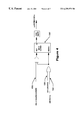
- FIG. 2 illustrates a representative ground proximity warning system incorporating the air-ground logic controller of FIG. 1;
- FIG. 3 illustrates a lamp block logic system incorporating the air-ground logic controller of FIG. 1;
- FIGS. 4-6 illustrate a decision height advisory callout system incorporating the air-ground logic controller of FIG. 1;
- FIG. 7 illustrates an auto rotation detection system according to the present invention.
- FIG. 1 an air-ground control system 10 for confirming whether a rotary wing aircraft is on the ground or in the air is illustrated in FIG. 1 .
- FIGS. 2-7 illustrate representative warning system and decision height advisory systems incorporating the air-ground control system of FIG. 1 .
- the air-ground control system 10 and the warning systems according to the invention are illustrated in a logical block diagrams as a series of gates, comparators and the like for purposes of illustration.
- the actual implementation of the logic can be other than as shown in the drawings, with various digital and analog implementations being possible.
- the implementation of the logic may be carried out by the computer readable code of software programs.
- the signals used by the system as described include radio altitude, barometric altitude rate and airspeed, along with various validity signals.
- the signals shown in the figures can be obtained from individual instruments, such as a barometric altimeter, a barometric rate circuit, a radio altimeter and an airspeed detector, which may be an air data computer or an airspeed indicator, and other discrete elements indicating whether the landing gear is up or down, etc.
- the signals can be obtained from a digital data bus in certain newer aircraft.
- control system 10 will form a portion of a larger Ground Proximity Warning System (GPWS) which provides warnings to the pilot when the aircraft is in danger of impacting the earth.
- GPWS Ground Proximity Warning System
- the aircraft data is collected from various sensors on the aircraft and processed in a digitally controlled warning computer to determine if the aircraft is in danger. Visual and aural outputs advise the pilot of dangerous situations and indicate if the system is operational.
- One such warning computer is the AlliedSignal MKVII Warning Computer for a rotary wing aircraft, which is commercially available from AlliedSignal Avionics Inc., Redmond, Wash.
- the GPWS preferably includes a number of warning modes to provide aural and visual alerts and warnings for unsafe proximity to terrain, deviation below ILS glide slope, excessive bank angle, onset of severe wind shear, altitude awareness, etc.
- Mode one for example, provides pilots with alert/warnings for high descent rates into terrain.
- a warning device compares the altitude above ground of the aircraft with the descent rate, preferably barometric descent rate, and issues a warning if the descent rate is excessive for the altitude at which the aircraft is flying.
- the descent rate preferably barometric descent rate
- Mode two provides warnings for excessive closure rates to terrain with respect to altitude (AGL), phase of flight and speed.
- Mode three provides warnings for significant altitude loss after takeoff or low altitude go around.
- a complete description of this system can be found in U.S. Pat. No. 4,818,992, the complete disclosure of which has previously been incorporated herein by reference.
- mode 4 provides alerts and warnings for insufficient terrain clearance with respect to phase of flight and speed.
- Mode 5 provides glide slope alerts when the airplane is below 1,000 ft. AGL with the gear down and the glide slope deviation exceeds a threshold number of dots below the ILS glide slope.
- mode six provides callouts for descent through predefined altitudes (AGL). In particular, mode six is utilized during autorotation when the aircraft has lost all or partial engine power.
- control system 10 includes a controller 12 that receives input from a number of sensors to determine whether the control system 10 is in an airborne state 14 or a ground state 16 .
- a pair of AND gates 32 and 50 receive inputs from a weight on wheel device 20 (“WOW”), a validity circuit 35 and an engine torque circuit 27 to set or reset a latch 46 that determines whether controller 12 is in the airborne state 14 or ground state 16 .
- WOW device 20 includes a force sensor (not shown) preferably located on or near the aircraft's wheel for detecting the weight placed on the wheel by the aircraft and a comparator or similar element (not shown) for determining whether the aircraft weight is above or below a threshold level.
- the threshold level will usually be set at a level that indicates that an aircraft is on the ground, which will vary depending on the weight of the aircraft.
- Engine torque circuit 27 includes a pair of engine torque sensors 22 , 24 placed on each engine to detect the torque being generated by the engines, and to input these values A,C into comparators 26 , 28 , respectively.
- Comparators 26 , 28 compare the inputs of torque sensors 22 , 24 with a reference torque B, D for each engine which indicates that the aircraft must be on the ground. Typical values for On Ground Torque are about 30%, but the values may vary from about 20% to about 40%. If engine torques A, C are less than on ground torque values B, D, respectively, comparators 26 , 28 input a true value to an AND gate 30 .
- the invention may be employed with only one torque sensor on one of the engines or engine.
- Controller 12 includes a validity circuit 35 for confirming that certain aspects of the warning computer are operational.
- Validity circuit 35 preferably receives inputs from a master valid input 36 , a simulator reposition input 38 and an unconfigured input 40 . As shown, if the aircraft is configured and the simulator is repositioning, or if master valid is true, a positive or true input will be applied from an OR gate 37 to AND gates 32 and 50 . If the system master valid is false and the simulator position is inactive, the state of the latch is prevented from changing.
- AND gate 32 receives inputs from validity circuit 35 , WOW device 20 and gate 30 of torque engine circuit 27 .
- Controller 12 includes another AND gate 50 which receives input from WOW device 20 and validity circuit 35 . If the WOW device 20 indicates that the weight on the aircraft's wheels is equal to or below a threshold level and the validity circuit is true, AND gate 50 will apply a positive output to latch circuit 60 .
- Latch circuit 60 includes latch 46 , an AND gate 54 , an OR gate 44 and a pair of delay mechanisms 42 , 52 . As shown, the outputs of AND gates 32 , 50 are delayed by delay mechanisms 42 , 52 , respectively, to minimize switch chattering and debouncing, usually between about 0 to 1 seconds.
- the signal from AND gate 32 is then applied to OR gate 44 along with an ATP signal 62 that indicates that ATP mode is in effect.
- the ATP input is a signal for driving the latch to the ground state during acceptance testing. If the aircraft is in ATP mode, or AND gate is positive 32 , a signal is applied to latch 46 to reset controller 12 to the ground state 16 .
- AND gate 54 receives input from the ATP signal 62 and gate 50 .
- the WOW sensor 20 indicates that the weight on the aircraft's wheels is equal to or below a threshold level and the validity circuit 27 is true, latch 46 is set to the airborne state 14 .
- latch 46 When the aircraft is on the ground, latch 46 will maintain controller 12 in ground state 16 . At this point, the weight on wheel signal 20 is true indicating that the weight is above the threshold level and the output from AND gate 30 is true indicating that the engine torques A, C are both below the ground reference torques B, D, respectively. When the aircraft takes off, the weight on the wheels suddenly decreases, which causes WOW signal 20 to inhibit AND gate 32 . If the validity circuit 27 is positive (i.e., the master valid input 36 is true or the simulator is repositioned and the aircraft is configured), the latch 46 will be reset into the airborne state 14 . The state of latch 46 is preferably maintained in a nonvolatile memory to prevent inadvertent change of state during loss of computer power.
- latch 46 is allowed to follow the new data values once filters have been released (i.e., not unconfigured). Ground state is also imposed whenever ATP mode is in effect, regardless of any other data.
- FIG. 2 illustrates the envelope or voice message logic for a mode 4 warning system that incorporates the air ground control system 10 shown in FIG. 1 .
- mode 4 warns pilots of insufficient terrain clearance during climb out cruise initial descent or approach. This warning mode is especially valuable when the aircraft's flight path relative to terrain is insufficient to develop excessive closure rate or descent rate warnings.
- the warning envelope on approach gradually collapses as speed decreases, the landing gear is lowered and the flaps selected. The wording of the warning is often changed to correlate with the phase of flight and the actual cause of alarm. Speed will automatically expand the warning envelope providing precious additional warning time for the pilot.
- a cockpit guarded flap override switch may be provided to eliminate possible nuisance alarms.
- warning system 100 receives input from a mode 4 C alert 102 and a mode 4 A/B alert 104 .
- Mode 4 A is generally active during cruising and approach with the landing gear not in landing configuration while mode 4 B is active during cruise and approach with the landing gear in the landing configuration.
- Mode 4 C is active after take-off or low altitude go-around with the landing gear not in a landing configuration.
- system 100 receives either one of these alerts 102 , 104 , a positive signal is input into an AND gate 106 . If the aircraft is in an airborne state (as discussed above in reference to FIG. 1 ), AND gate 106 will enable the warning “TOO LOW, TERRAIN”. This message will generally only be repeated twice unless terrain clearance continues to decrease. For mode 4 A or mode 4 B, this message will only be enabled if the air speed is higher than a minimum reference value.
- an AND gate 108 receives the air speed and minimum warning altitude inputs 110 , 112 .
- AND gate 108 will send a positive signal to an OR gate 114 .
- the system will enable an oral message “TOO LOW, GEAR”.
- Warning system 100 further includes a latch 120 that is reset by a mode 4 pullup lamp 122 (See FIG. 3 ).
- Latch 120 is set when it is enabled by an AND gate 124 having inputs from a minimum airspeed check 126 , a mode 4 A/B lamp input 128 , and an airspeed circuit 130 .
- AND gate 124 enables OR gate 114 such that AND gate 116 enables the “TOO LOW GEAR” aural warning if the aircraft is in the airborne state and if the landing gears are up.
- the mode 4 pullup lamp will be activated (and latch 120 reset, see FIG. 2) if it is enabled by an AND gate 130 which receives input from the air-ground controller 10 of FIG. 1 and a terrain clearance circuit 132 .
- Terrain clearance circuit 132 includes an OR gate 134 which enables AND gate 130 if the terrain clearance is less than a limited floor value.
- an OR gate 136 will be enabled by AND gates 138 , 140 .
- OR gate 136 will be enabled by AND gates 142 , 140 . In any of these instances, the mode 4 pullup lamp will be activated to reset latch 120 (FIG. 2 ).
- FIGS. 4-6 illustrate a decision height advisory callout system that may be used in conjunction with the air/ground controller 10 of FIG. 1 .
- This logic will be used in mode 6 , which provides callouts for descent through predefined altitudes (AGL) including descent to decision heights.
- the mode 6 callout function is typically active during the final approach phase of flight.
- the logic includes a decision height A latch 150 that may be reset manually by the pilot 152 , or if the air-ground controller 10 of FIG. 1 indicates a ground state 154 .
- the latch 150 is set if the decision height A 156 is transitioned by the aircraft, and if the aircraft is not on the ground (i.e., in the airborne state).
- FIG. 5 illustrates a similar logic diagram for the decision height B.
- a latch 160 is reset if the aircraft is in the ground state, or if the decision height message has already been completed.
- the latch 152 is set when decision height B is transitioned and the aircraft is in the airborne state.
- the voice logic for mode 6 includes a voice latch 170 that is reset when the aircraft is in the ground state 172 , the ground proximity warning is inhibited 174 , or decision height messages A or B have ended 176 .
- Voice latch 170 is set if: (1) either decision height A or B have been latched 178 (as discussed in FIGS. 4 and 5 ); (2) the aircraft is not on the ground; (3) the ground proximity warning has not been inhibited; and (4) the decision height messages have not ended.
- a first AND gate 178 enables the “minimums minimums” message if the latch is set, the enable A logic (not shown) is positive and the master is valid.
- a second AND gate 180 enables the “altitude altitude” message if the latch is set, the enable B circuit 182 is positive and the master is valid 184 .
- an auto rotation detection system 200 is illustrated according to the present invention.
- Auto rotation typically occurs when a helicopter suffers an engine failure, and the rotors continue to rotate due to the velocity of the helicopter through the air.
- This auto rotation provides enough lift to the helicopter to allow the pilot to maneuver the helicopter down to the ground at a reasonably controlled rate although substantially faster than the normal descent rate.
- the auto rotation detection system is activated or enabled by an AND gate 202 that receives input from engine torque indicators and the air-ground controller 10 of FIG. 1 .
- the engine torques of engine number 1 and engine number 2 are each compared to a reference auto rotation torque value with comparators 204 , 206 .
- both engine torques are lower than the reference auto rotation torque values, the aircraft must be in auto rotation if it is airborne. Accordingly, if: (1) both torque values are below the reference value; (2)the torque serial buses for each engine torque sensor are valid; and (3) if the airplane is in the airborne state, AND gate 202 enables the auto rotation warning.
Abstract
The present invention provides ground proximity warning system and method for aircraft, particularly rotary wing aircraft such as helicopters. The warning system generally includes an air ground detection device disposed on the aircraft to confirm whether the aircraft is on the ground or in the air. A controller is coupled to the air ground detection device and configured to move between a ground state when the aircraft is on the ground and an airborne state when the aircraft is in the air. The controller may be used for a variety of applications within the aircraft, such as disabling a ground proximity warning device when the aircraft is on the ground and enabling the warning device when the aircraft is in the air. In addition, the air ground controller may be used to signal the beginning and the end of a flight for the aircraft's flight history fault memory.
Description
This application claims priority from U.S. provisional application Ser. No. 60/022,081 filed Jul. 29, 1996, and is a divisional of application Ser. No. 08/846,962 filed Apr. 29, 1997, now U.S. Pat. No. 6,043,759.
This application is related to concurrently filed and commonly assigned patent applications entitled “Ground Proximity Warning System and Methods for Rotary Wing Aircraft” (Attorney Docket No. 543-96-007/T-S-004), and “Systems and Methods for Generating Altitude Callouts for Rotary Wing Aircraft” (Attorney Docket No. 543-96-008/T-S-006), the complete disclosures of which are incorporated herein by reference.
The present invention relates generally to ground proximity warning devices and more particularly to systems and methods for enabling such ground proximity warning devices in rotary wing aircraft.
Ground proximity warning systems provide aural and visual warnings of aircraft descent after takeoffs, landings, during a go-around after a missed approach and other low altitude flying conditions. These systems typically detect altitude loss by computing the barometric altitude (MSL) rate change. The radio altitude or altitude above ground level (AGL) is then determined with a radio altimeter. The warning device typically issues a number of aural or visual warnings if the altitude loss is excessive for the radio altitude at which the aircraft is flying. For example, one such system, compares the accumulated altitude loss after takeoff of the aircraft, and generates a warning if the altitude loss exceeds a predetermined value before a threshold altitude has been reached. Examples of such a system are disclosed in commonly assigned U.S. Pat. Nos. 3,946,358, 3,947,808 and 4,818,992, the complete disclosures of which are incorporated herein by reference. Another type of warning system warns the pilot in the event that the aircraft if descending too rapidly, particularly on approach to a landing. Examples of this type of warning system are disclosed in commonly assigned U.S. Pat. Nos. 3,958,358 4,215,334 and 4,551,723, the complete disclosures of which are also incorporated herein by reference.
The present invention is particularly concerned with ground proximity warning devices for rotary wing aircraft, such as helicopters. Most conventional ground proximity warning systems are designed to operate with transport aircraft, particularly with large turbine powered aircraft, such as those flown by commercial airlines. Since rotary wing aircraft are highly maneuverable, they typically have flight operational characteristics entirely different than that of transport aircraft. Consequently, the systems designed for transport aircraft can generate nuisance warnings during certain normal operational conditions in rotary wing aircraft. In addition, these warning systems may provide no warning or an inadequate warning during other flight conditions. Thus, a pilot may tend to ignore the warnings provided by such systems, rendering them ineffective.
The present invention provides ground proximity warning systems and methods for rotary wing aircraft such as helicopters. The warning system of the present invention includes an air ground detection device disposed on the aircraft to confirm whether the aircraft is on the ground or in the air. A controller is coupled to the air ground detection device and configured to move between a ground state when the aircraft is on the ground and an airborne state when the aircraft is in the air. The controller may be used for a variety of applications within the aircraft, such as disabling a ground proximity warning device when the aircraft is on the ground and enabling the warning device when the aircraft is in the air. In addition, the air ground controller may be used to signal the beginning and the end of a flight for the aircraft's flight history fault memory. For example, when the controller switches from the ground state to the airborne state, the warning may include a switch for enabling the flight history fault memory. When the control switches back to the ground state, the switch will disable the flight history flight memory to signify the end of the flight.
In a specific configuration, the warning system includes one or more sensors for sensing certain aircraft conditions that will indicate whether the aircraft is on the ground or in the air. Preferably, the sensors include one or more force sensors placed on or near the aircraft's wheel to detect the weight placed thereon. When the weight is above a threshold level that indicates the aircraft's weight is being placed on the wheels, the controller will switch into the ground state. When the weight falls below the threshold level, the controller will switch back to the airborne state indicating that the aircraft has taken off. The control system further includes a latch that holds the controller in either the airborne or ground state until it is reset by one or more flight conditions. For example, prior to takeoff, the latch will hold the controller in the ground state. The latch will not reset and allow the controller to move into the airborne state until the force sensor(s) detect an aircraft weight greater than the threshold weight.
The weight sensors are typically placed exterior to the aircraft and, therefore, are subject to environmental conditions such as adverse weather and the like. Accordingly, the invention may include an additional, redundant detection method to prevent erroneous airborne indication due to errors in the weight sensors. In an exemplary embodiment, the system further includes one or more engine torque detectors for detecting the total engine torque of one or more of the aircraft's engines. In this embodiment, the controller will move into the ground state when the weight on the wheels is above the threshold level and when the engine torque is below a threshold level, which would indicate that the aircraft is not providing enough torque to lift the helicopter above the ground.
In an exemplary embodiment, a ground proximity warning computer is provided for a rotary wing aircraft, e.g., a Sikorsky S-76 Aircraft. The warning computer provides warnings to the pilot when the aircraft is in danger of impacting the earth. The aircraft data is collected from various sensors on the aircraft and processed in a digitally controlled warning computer to determine if the aircraft is in danger. Visual and aural outputs advise the pilot of dangerous situations and indicate if the system is operational. According to the present invention, the warning computer includes a ground proximity warning device having an alarm for generating a visual and/or aural warning based on one or more flight condition(s) of the aircraft. This ground proximity warning device can provide a variety of warnings to the pilot(s), such as excessive descent rate, excessive closure to terrain, altitude loss after take-off, unsafe terrain clearance, altitude awareness callouts and the like.
The controller of the present invention is coupled to one or more of the warning devices and disposed to disable the warning devices when the aircraft is on the ground. Consequently, the warning devices will generate less nuisance warnings during certain normal operational conditions of the rotary wing aircraft so that the pilot will not be tempted to ignore the warnings provided by such systems.
FIG. 1 is a functional block diagram of an air-ground logic controller according to the present invention;
FIG. 2 illustrates a representative ground proximity warning system incorporating the air-ground logic controller of FIG. 1;
FIG. 3 illustrates a lamp block logic system incorporating the air-ground logic controller of FIG. 1;
FIGS. 4-6 illustrate a decision height advisory callout system incorporating the air-ground logic controller of FIG. 1; and
FIG. 7 illustrates an auto rotation detection system according to the present invention.
Referring to the drawings in detail, wherein like numerals indicate like elements, an air-ground control system 10 for confirming whether a rotary wing aircraft is on the ground or in the air is illustrated in FIG. 1. FIGS. 2-7 illustrate representative warning system and decision height advisory systems incorporating the air-ground control system of FIG. 1. The air-ground control system 10 and the warning systems according to the invention are illustrated in a logical block diagrams as a series of gates, comparators and the like for purposes of illustration. However, it should be understood that the actual implementation of the logic can be other than as shown in the drawings, with various digital and analog implementations being possible. Alternatively, the implementation of the logic may be carried out by the computer readable code of software programs. The signals used by the system as described include radio altitude, barometric altitude rate and airspeed, along with various validity signals. Depending on the type of aircraft in which the warning system is installed, the signals shown in the figures can be obtained from individual instruments, such as a barometric altimeter, a barometric rate circuit, a radio altimeter and an airspeed detector, which may be an air data computer or an airspeed indicator, and other discrete elements indicating whether the landing gear is up or down, etc. Alternatively, the signals can be obtained from a digital data bus in certain newer aircraft.
In an exemplary embodiment, control system 10 will form a portion of a larger Ground Proximity Warning System (GPWS) which provides warnings to the pilot when the aircraft is in danger of impacting the earth. The aircraft data is collected from various sensors on the aircraft and processed in a digitally controlled warning computer to determine if the aircraft is in danger. Visual and aural outputs advise the pilot of dangerous situations and indicate if the system is operational. One such warning computer is the AlliedSignal MKVII Warning Computer for a rotary wing aircraft, which is commercially available from AlliedSignal Avionics Inc., Redmond, Wash.
The GPWS preferably includes a number of warning modes to provide aural and visual alerts and warnings for unsafe proximity to terrain, deviation below ILS glide slope, excessive bank angle, onset of severe wind shear, altitude awareness, etc. Mode one, for example, provides pilots with alert/warnings for high descent rates into terrain. In this mode, a warning device compares the altitude above ground of the aircraft with the descent rate, preferably barometric descent rate, and issues a warning if the descent rate is excessive for the altitude at which the aircraft is flying. A more complete description of an exemplary warning device for indicating excessive descent rate can be found in U.S. Pat. No. 4,551,723, the complete disclosure of which has previously been incorporated herein by reference. Mode two provides warnings for excessive closure rates to terrain with respect to altitude (AGL), phase of flight and speed. Mode three provides warnings for significant altitude loss after takeoff or low altitude go around. A complete description of this system can be found in U.S. Pat. No. 4,818,992, the complete disclosure of which has previously been incorporated herein by reference.
As discussed below with reference to FIGS. 2 and 3, mode 4 provides alerts and warnings for insufficient terrain clearance with respect to phase of flight and speed. Mode 5 provides glide slope alerts when the airplane is below 1,000 ft. AGL with the gear down and the glide slope deviation exceeds a threshold number of dots below the ILS glide slope. As discussed below with reference to FIGS. 4-7, mode six provides callouts for descent through predefined altitudes (AGL). In particular, mode six is utilized during autorotation when the aircraft has lost all or partial engine power.
Referring to FIG. 1, control system 10 includes a controller 12 that receives input from a number of sensors to determine whether the control system 10 is in an airborne state 14 or a ground state 16. In the exemplary embodiment, a pair of AND gates 32 and 50 receive inputs from a weight on wheel device 20 (“WOW”), a validity circuit 35 and an engine torque circuit 27 to set or reset a latch 46 that determines whether controller 12 is in the airborne state 14 or ground state 16. WOW device 20 includes a force sensor (not shown) preferably located on or near the aircraft's wheel for detecting the weight placed on the wheel by the aircraft and a comparator or similar element (not shown) for determining whether the aircraft weight is above or below a threshold level. The threshold level will usually be set at a level that indicates that an aircraft is on the ground, which will vary depending on the weight of the aircraft. Engine torque circuit 27 includes a pair of engine torque sensors 22, 24 placed on each engine to detect the torque being generated by the engines, and to input these values A,C into comparators 26, 28, respectively. Comparators 26, 28 compare the inputs of torque sensors 22, 24 with a reference torque B, D for each engine which indicates that the aircraft must be on the ground. Typical values for On Ground Torque are about 30%, but the values may vary from about 20% to about 40%. If engine torques A, C are less than on ground torque values B, D, respectively, comparators 26, 28 input a true value to an AND gate 30. In addition, the invention may be employed with only one torque sensor on one of the engines or engine.
As shown in FIG. 1, AND gate 32 receives inputs from validity circuit 35, WOW device 20 and gate 30 of torque engine circuit 27. Thus, if: (1) the WOW device 20 indicates that the weight on the wheel is above a threshold level; (2) the validity circuit 35 is true; and (3) both engine torque values A, C are less than the on ground torque values B, D, AND gate 32 will apply a positive output to a latch circuit 60. Controller 12 includes another AND gate 50 which receives input from WOW device 20 and validity circuit 35. If the WOW device 20 indicates that the weight on the aircraft's wheels is equal to or below a threshold level and the validity circuit is true, AND gate 50 will apply a positive output to latch circuit 60.
When the aircraft is on the ground, latch 46 will maintain controller 12 in ground state 16. At this point, the weight on wheel signal 20 is true indicating that the weight is above the threshold level and the output from AND gate 30 is true indicating that the engine torques A, C are both below the ground reference torques B, D, respectively. When the aircraft takes off, the weight on the wheels suddenly decreases, which causes WOW signal 20 to inhibit AND gate 32. If the validity circuit 27 is positive (i.e., the master valid input 36 is true or the simulator is repositioned and the aircraft is configured), the latch 46 will be reset into the airborne state 14. The state of latch 46 is preferably maintained in a nonvolatile memory to prevent inadvertent change of state during loss of computer power.
The normal latch logic is only enabled when master valid 36 is true. However, when repositioning, latch 46 is allowed to follow the new data values once filters have been released (i.e., not unconfigured). Ground state is also imposed whenever ATP mode is in effect, regardless of any other data.
FIG. 2 illustrates the envelope or voice message logic for a mode 4 warning system that incorporates the air ground control system 10 shown in FIG. 1. As discussed above, mode 4 warns pilots of insufficient terrain clearance during climb out cruise initial descent or approach. This warning mode is especially valuable when the aircraft's flight path relative to terrain is insufficient to develop excessive closure rate or descent rate warnings. Preferably, the warning envelope on approach gradually collapses as speed decreases, the landing gear is lowered and the flaps selected. The wording of the warning is often changed to correlate with the phase of flight and the actual cause of alarm. Speed will automatically expand the warning envelope providing precious additional warning time for the pilot. In the event of full or partial flap landings, a cockpit guarded flap override switch may be provided to eliminate possible nuisance alarms.
Referring to FIG. 2, warning system 100 receives input from a mode 4C alert 102 and a mode 4A/B alert 104. Mode 4A is generally active during cruising and approach with the landing gear not in landing configuration while mode 4B is active during cruise and approach with the landing gear in the landing configuration. Mode 4C is active after take-off or low altitude go-around with the landing gear not in a landing configuration. If system 100 receives either one of these alerts 102, 104, a positive signal is input into an AND gate 106. If the aircraft is in an airborne state (as discussed above in reference to FIG. 1), AND gate 106 will enable the warning “TOO LOW, TERRAIN”. This message will generally only be repeated twice unless terrain clearance continues to decrease. For mode 4A or mode 4B, this message will only be enabled if the air speed is higher than a minimum reference value.
As shown in FIG. 2, an AND gate 108 receives the air speed and minimum warning altitude inputs 110, 112. In addition, if the mode 4 biased altitude is less than an initial warning altitude, AND gate 108 will send a positive signal to an OR gate 114. In this case, if the landing gears are up, and the air-ground controller 10 is in the airborne state, the system will enable an oral message “TOO LOW, GEAR”.
Referring to FIG. 3, the preferred logic for a mode 4 pullup lamp warning is illustrated. As shown, the mode 4 pullup lamp will be activated (and latch 120 reset, see FIG. 2) if it is enabled by an AND gate 130 which receives input from the air-ground controller 10 of FIG. 1 and a terrain clearance circuit 132. Terrain clearance circuit 132 includes an OR gate 134 which enables AND gate 130 if the terrain clearance is less than a limited floor value. Alternatively, if the aircraft's change in altitude is less than a lamp slope value and the aircraft is flying at an altitude greater than a minimum warning altitude, an OR gate 136 will be enabled by AND gates 138, 140. Alternatively, if the terrain clearance is less than an initial warning altitude and the altitude is greater than a minimum warning altitude, OR gate 136 will be enabled by AND gates 142, 140. In any of these instances, the mode 4 pullup lamp will be activated to reset latch 120 (FIG. 2).
FIGS. 4-6 illustrate a decision height advisory callout system that may be used in conjunction with the air/ground controller 10 of FIG. 1. This logic will be used in mode 6, which provides callouts for descent through predefined altitudes (AGL) including descent to decision heights. The mode 6 callout function is typically active during the final approach phase of flight. As shown in FIG. 4, the logic includes a decision height A latch 150 that may be reset manually by the pilot 152, or if the air-ground controller 10 of FIG. 1 indicates a ground state 154. Similarly, the latch 150 is set if the decision height A 156 is transitioned by the aircraft, and if the aircraft is not on the ground (i.e., in the airborne state).
FIG. 5 illustrates a similar logic diagram for the decision height B. As shown, a latch 160 is reset if the aircraft is in the ground state, or if the decision height message has already been completed. Similarly, the latch 152 is set when decision height B is transitioned and the aircraft is in the airborne state.
Referring to FIG. 6, the voice logic for mode 6 includes a voice latch 170 that is reset when the aircraft is in the ground state 172, the ground proximity warning is inhibited 174, or decision height messages A or B have ended 176. Voice latch 170 is set if: (1) either decision height A or B have been latched 178 (as discussed in FIGS. 4 and 5); (2) the aircraft is not on the ground; (3) the ground proximity warning has not been inhibited; and (4) the decision height messages have not ended. As shown, a first AND gate 178 enables the “minimums minimums” message if the latch is set, the enable A logic (not shown) is positive and the master is valid. Similarly, a second AND gate 180 enables the “altitude altitude” message if the latch is set, the enable B circuit 182 is positive and the master is valid 184.
Referring to FIG. 7, an auto rotation detection system 200 is illustrated according to the present invention. Auto rotation typically occurs when a helicopter suffers an engine failure, and the rotors continue to rotate due to the velocity of the helicopter through the air. This auto rotation provides enough lift to the helicopter to allow the pilot to maneuver the helicopter down to the ground at a reasonably controlled rate although substantially faster than the normal descent rate. As shown in FIG. 7, the auto rotation detection system is activated or enabled by an AND gate 202 that receives input from engine torque indicators and the air-ground controller 10 of FIG. 1. Specifically, the engine torques of engine number 1 and engine number 2 are each compared to a reference auto rotation torque value with comparators 204, 206. If both engine torques are lower than the reference auto rotation torque values, the aircraft must be in auto rotation if it is airborne. Accordingly, if: (1) both torque values are below the reference value; (2)the torque serial buses for each engine torque sensor are valid; and (3) if the airplane is in the airborne state, AND gate 202 enables the auto rotation warning.
Claims (7)
1. A ground proximity warning system for rotary wing aircraft comprising:
a sensor disposed on the aircraft to detect a flight condition;
a warning computer having an input connected to the sensor, the warning computer including a controller coupled to the input for generating a signal representing the flight condition and a warning device coupled to the controller for receiving the signals and generating an aural warning to the pilot indicating the flight condition; and
an air-ground detector wherein the air-ground detector comprises an engine torque detector disposed to detect the torque of one or more of the aircraft's engines, wherein the condition when the torque is below one of an on ground torque or an autorotation torque is a sufficient condition for causing the controller to move into a ground state whereby said air-ground detector is disposed to detect whether the aircraft is on the ground or in the air, the air-ground detector being coupled to the warning computer and disposed to disable the controller or the warning device when the aircraft is on the ground.
2. The warning system of claim 1 wherein the air-ground detector enables the warning computer when the aircraft is in the air.
3. The warning system of claim 1 wherein the air-ground detector comprises a force sensor positioned on or near the aircraft's wheel for detecting the weight placed on the wheel, wherein the controller moves into the ground state when the sensor detects a threshold weight.
4. The warning system of claim 1 wherein the sensor is an altitude detector disposed to detect the altitude of the aircraft, the controller is coupled to said detector and disposed to generate signals representative of the altitude of the aircraft, and the warning device is coupled to the controller for receiving the signals and generating an aural warning to the pilot indicating the altitude.
5. A method for warning a pilot of a flight condition in a rotary wing aircraft, the method comprising:
sensing a weight placed on the aircraft's wheel;
determining a torque of the aircraft's engine;
determining whether the aircraft is in the air or on the ground based on said weight; and torque;
if the aircraft is in the air, generating a warning to the pilot based on one or more flight conditions and wherein the warning is generated only when both the torque is above an on-ground torque and an autorotation torque and the weight is below a threshold weight, in order to avoid a nuisance warning when the aircraft is on the ground or under an engine failure condition.
6. The method of claim 5 further comprising comparing said weight to a threshold weight to determine whether the aircraft is in the air.
7. The method of claim 5 further comprising:
detecting the radio altitude of the rotary wing aircraft;
determining whether the radio altitude is one of a plurality of preselected altitude callouts;
generating signals representative of the radio altitude if the radio altitude is one of said plurality of preselected altitude callouts; and
if the aircraft is in the air, issuing an aural warning to the pilot indicating the radio altitude of the aircraft.
Priority Applications (1)
| Application Number | Priority Date | Filing Date | Title |
|---|---|---|---|
| US09/450,834 US6259379B1 (en) | 1996-07-29 | 1999-11-29 | Air-ground logic system and method for rotary wing aircraft |
Applications Claiming Priority (3)
| Application Number | Priority Date | Filing Date | Title |
|---|---|---|---|
| US2208196P | 1996-07-29 | 1996-07-29 | |
| US08/846,962 US6043759A (en) | 1996-07-29 | 1997-04-29 | Air-ground logic system and method for rotary wing aircraft |
| US09/450,834 US6259379B1 (en) | 1996-07-29 | 1999-11-29 | Air-ground logic system and method for rotary wing aircraft |
Related Parent Applications (1)
| Application Number | Title | Priority Date | Filing Date |
|---|---|---|---|
| US08/846,962 Division US6043759A (en) | 1996-07-29 | 1997-04-29 | Air-ground logic system and method for rotary wing aircraft |
Publications (1)
| Publication Number | Publication Date |
|---|---|
| US6259379B1 true US6259379B1 (en) | 2001-07-10 |
Family
ID=26695483
Family Applications (2)
| Application Number | Title | Priority Date | Filing Date |
|---|---|---|---|
| US08/846,962 Expired - Lifetime US6043759A (en) | 1996-07-29 | 1997-04-29 | Air-ground logic system and method for rotary wing aircraft |
| US09/450,834 Expired - Lifetime US6259379B1 (en) | 1996-07-29 | 1999-11-29 | Air-ground logic system and method for rotary wing aircraft |
Family Applications Before (1)
| Application Number | Title | Priority Date | Filing Date |
|---|---|---|---|
| US08/846,962 Expired - Lifetime US6043759A (en) | 1996-07-29 | 1997-04-29 | Air-ground logic system and method for rotary wing aircraft |
Country Status (1)
| Country | Link |
|---|---|
| US (2) | US6043759A (en) |
Cited By (26)
| Publication number | Priority date | Publication date | Assignee | Title |
|---|---|---|---|---|
| US20050015202A1 (en) * | 2002-05-15 | 2005-01-20 | Honeywell International, Inc. | Ground operations and advanced runway awareness and advisory system |
| US20050128129A1 (en) * | 2001-03-06 | 2005-06-16 | Honeywell International, Inc. | Ground operations and imminent landing runway selection |
| US6961445B1 (en) * | 2001-05-04 | 2005-11-01 | Rockwell Collins | Image processing warning system |
| US20060007463A1 (en) * | 2004-07-09 | 2006-01-12 | Savov Andrey I | Method and apparatus for effective job management |
| US7284420B2 (en) | 2004-07-13 | 2007-10-23 | Honeywell International Inc. | Air data system and method for rotary aircraft |
| US20070282493A1 (en) * | 2006-06-02 | 2007-12-06 | Sikorsky Aircraft Corporation | Surface contact override landing scheme for a FBW rotary-wing aircraft |
| US20080117858A1 (en) * | 2006-11-21 | 2008-05-22 | Honeywell International Inc. | System and method for transmitting information using aircraft as transmission relays |
| US20090002196A1 (en) * | 2007-05-24 | 2009-01-01 | Zweifel Terry L | Systems and methods for aircraft windshear detection |
| US20090040963A1 (en) * | 2007-08-08 | 2009-02-12 | Honeywell International Inc. | Gatelink startup controlled by acars cmu |
| US20090041041A1 (en) * | 2007-08-08 | 2009-02-12 | Honeywell International Inc. | Aircraft data link network routing |
| US20090082013A1 (en) * | 2007-09-20 | 2009-03-26 | Honeywell International Inc. | System and method for wireless routing of data from an aircraft |
| US20090103473A1 (en) * | 2007-10-19 | 2009-04-23 | Honeywell International Inc. | Method to establish and maintain an aircraft ad-hoc communication network |
| US20090103452A1 (en) * | 2007-10-19 | 2009-04-23 | Honeywell International Inc. | Ad-hoc secure communication networking based on formation flight technology |
| US20090141669A1 (en) * | 2007-12-04 | 2009-06-04 | Honeywell International Inc. | Travel characteristics-based ad-hoc communication network algorithm selection |
| US20090197595A1 (en) * | 2008-02-04 | 2009-08-06 | Honeywell International Inc. | Use of alternate communication networks to complement an ad-hoc mobile node to mobile node communication network |
| US20090210105A1 (en) * | 2006-05-15 | 2009-08-20 | Lusby Brock D | Air-ground detection system and method |
| US20090318137A1 (en) * | 2008-06-20 | 2009-12-24 | Honeywell International Inc. | Internetworking air-to-air network and wireless network |
| US20090318138A1 (en) * | 2008-06-20 | 2009-12-24 | Honeywell International Inc. | System and method for in-flight wireless communication |
| US20110202207A1 (en) * | 2010-02-16 | 2011-08-18 | Airbus Operations (S.A.S.) | Method And Device For Automatically Protecting An Aircraft Against An Excessive Descent Rate |
| US20120068015A1 (en) * | 2010-09-14 | 2012-03-22 | Eurocopter | Method of activating protection means for protecting an occupant of an aircraft, and an aircraft implementing said method |
| US8145367B2 (en) | 2001-03-06 | 2012-03-27 | Honeywell International Inc. | Closed airport surface alerting system |
| US20140124620A1 (en) * | 2010-07-07 | 2014-05-08 | Giacomo Giovangrossi | Method and system for emergency landing of a vehicle |
| US8862377B2 (en) | 2011-03-31 | 2014-10-14 | Sikorsky Aircraft Corporation | Method and system for detecting forces on aircraft |
| US9354635B2 (en) | 2012-06-05 | 2016-05-31 | Textron Innovations Inc. | Takeoff/landing touchdown protection management system |
| US11265792B2 (en) * | 2017-08-11 | 2022-03-01 | Lenovo (Beijing) Co. Ltd | Aerial vehicle state transition |
| US11352900B2 (en) | 2019-05-14 | 2022-06-07 | Pratt & Whitney Canada Corp. | Method and system for operating a rotorcraft engine |
Families Citing this family (15)
| Publication number | Priority date | Publication date | Assignee | Title |
|---|---|---|---|---|
| DE60138017D1 (en) * | 2000-05-26 | 2009-04-30 | Honeywell Int Inc | Device, method and computer program product for a helicopter ground proximity warning system |
| US6583733B2 (en) | 2000-05-26 | 2003-06-24 | Honeywell International Inc. | Apparatus, method and computer program product for helicopter ground proximity warning system |
| US6833797B2 (en) | 2000-05-26 | 2004-12-21 | Honeywell International Inc. | Method, apparatus and computer program product for displaying terrain in rotary wing aircraft |
| WO2002023125A1 (en) | 2000-09-14 | 2002-03-21 | Honeywell International Inc. | Method, apparatus and computer program product for helicopter tail strike warning |
| US7009531B2 (en) * | 2001-07-23 | 2006-03-07 | Ram Pattisapu | System for aurally monitoring aeronautical information while in flight |
| US7088264B2 (en) * | 2002-03-14 | 2006-08-08 | Honeywell International Inc. | Flight safety system monitoring combinations of state values |
| US7203967B2 (en) * | 2003-09-10 | 2007-04-10 | Qualcomm Incorporated | Methods and apparatus for content protection in a wireless network |
| US7126496B2 (en) * | 2004-09-30 | 2006-10-24 | Safe Flight Instrument Corporation | Tactile cueing system and method for aiding a helicopter pilot in making landings |
| US7598888B2 (en) * | 2006-12-08 | 2009-10-06 | Sikorsky Aircraft Corporation | Rotary wing aircraft proximity warning system with a geographically based avoidance system |
| US10227140B2 (en) * | 2014-07-11 | 2019-03-12 | Cmc Electronics Inc | System and method for detecting and alerting the user of an aircraft of an impendent adverse condition |
| US20160221686A1 (en) * | 2015-02-02 | 2016-08-04 | Honeywell International Inc. | Systems and methods for alerting helicopter pilots to undesirable operating conditions during landing operations |
| FR3035978A1 (en) * | 2015-05-04 | 2016-11-11 | Airbus Helicopters | GIRAVION CONTROL SYSTEM, ASSOCIATED GIRAVION AND CORRESPONDING CONTROL METHOD |
| US9738399B2 (en) * | 2015-07-29 | 2017-08-22 | Hon Hai Precision Industry Co., Ltd. | Unmanned aerial vehicle control method and unmanned aerial vehicle using same |
| WO2017034658A1 (en) | 2015-08-24 | 2017-03-02 | Sikorsky Aircraft Corporation | Vibratory weight-on-wheels sensing |
| CN105509708B (en) * | 2015-11-21 | 2019-09-03 | 西安科技大学 | A kind of determination method of seam mining subsidence coefficient under Loess Gullys |
Citations (5)
| Publication number | Priority date | Publication date | Assignee | Title |
|---|---|---|---|---|
| US4293840A (en) * | 1978-05-25 | 1981-10-06 | Israel Aircraft Industries Ltd. | Excessive descent-rate warning system particularly useful for helicopters |
| US4355294A (en) * | 1980-05-02 | 1982-10-19 | Automation Industries, Inc. | Altitude alert system |
| US4987413A (en) * | 1985-02-22 | 1991-01-22 | Sundstrand Data Control, Inc. | Aircraft terrain warning system with configuration modified warning and improved mode switching |
| US5666110A (en) * | 1995-03-09 | 1997-09-09 | Paterson; Noel S. | Helicopter enhanced descent after take-off warning for GPWS |
| US5826833A (en) * | 1995-05-15 | 1998-10-27 | The Boeing Company | System for providing an air/ground signal to aircraft flight control systems |
Family Cites Families (50)
| Publication number | Priority date | Publication date | Assignee | Title |
|---|---|---|---|---|
| US3616691A (en) * | 1969-03-26 | 1971-11-02 | Bendix Corp | Mission capability indicating system |
| US3715718A (en) * | 1970-08-11 | 1973-02-06 | Sundstrand Data Control | Ground proximity warning system utilizing radio and barometric altimeter combination |
| US3936796A (en) * | 1974-06-19 | 1976-02-03 | Sundstrand Data Control, Inc. | Aircraft ground proximity warning instrument |
| US3958218A (en) * | 1974-10-03 | 1976-05-18 | Sundstrand Data Control, Inc. | Aircraft ground proximity warning system with speed compensation |
| US3944968A (en) * | 1974-11-01 | 1976-03-16 | Sundstrand Data Control, Inc. | Aircraft ground proximity warning system having speed versus altitude compensation |
| US4063073A (en) * | 1974-11-29 | 1977-12-13 | Strayer Larry G | Computer system to prevent collision between moving objects such as aircraft moving from one sector to another |
| US3947808A (en) * | 1975-01-13 | 1976-03-30 | Sundstrand Data Control, Inc. | Excessive descent rate warning system for aircraft |
| US3947810A (en) * | 1975-01-13 | 1976-03-30 | Sundstrand Data Control, Inc. | Negative climb rate after take-off warning system with predetermined loss of altitude inhibit |
| US3934221A (en) * | 1975-03-06 | 1976-01-20 | Sundstrand Data Control, Inc. | Terrain closure warning system with altitude rate signal conditioning |
| US3958219A (en) * | 1975-03-06 | 1976-05-18 | Sundstrand Data Control, Inc. | Terrain closure warning system with altitude rate signal conditioning |
| US3934222A (en) * | 1975-04-02 | 1976-01-20 | Sundstrand Data Control, Inc. | Terrain closure warning system with climb inhibit and altitude gain measurement |
| US3925751A (en) * | 1975-04-02 | 1975-12-09 | Sundstrand Data Control | Glide slope warning system with a variable warning rate |
| US4060793A (en) * | 1976-07-19 | 1977-11-29 | Sundstrand Data Control, Inc. | Excessive sink rate warning system for aircraft |
| US4030065A (en) * | 1976-07-19 | 1977-06-14 | Sundstrand Corporation | Terrain clearance warning system for aircraft |
| US4121194A (en) * | 1976-09-30 | 1978-10-17 | The Boeing Company | Take-off warning system for aircraft |
| US4093938A (en) * | 1976-10-18 | 1978-06-06 | Intercontinental Dynamics Corp. | Aircraft altitude annunciator |
| US4224669A (en) * | 1977-12-22 | 1980-09-23 | The Boeing Company | Minimum safe altitude monitoring, indication and warning system |
| US4215334A (en) * | 1978-02-09 | 1980-07-29 | Sundstrand Data Control, Inc. | Aircraft excessive descent rate warning system |
| US4319218A (en) * | 1980-01-04 | 1982-03-09 | Sundstrand Corporation | Negative climb after take-off warning system with configuration warning means |
| DE3228557A1 (en) * | 1982-07-30 | 1984-02-09 | Ulrich 8000 München Trampnau | WARNING DEVICE FOR HELICOPTER |
| US4567483A (en) * | 1982-12-10 | 1986-01-28 | Sundstrand Data Control, Inc. | Position based ground proximity warning system for aircraft |
| US4916447A (en) * | 1983-05-13 | 1990-04-10 | Sundstrand Data Control, Inc. | Warning system for aircraft landing with landing gear up |
| US4951047A (en) * | 1983-05-13 | 1990-08-21 | Sunstrand Data Control, Inc. | Negative climb after take-off warning system |
| US4980684A (en) * | 1983-06-10 | 1990-12-25 | Sundstrand Data Controls, Inc. | Warning system for tactical rotary wing aircraft |
| US4551723A (en) * | 1983-06-10 | 1985-11-05 | Sundstrand Data Control, Inc. | Excessive descent rate warning system for rotary wing aircraft |
| US4818992A (en) * | 1983-06-10 | 1989-04-04 | Sundstrand Data Control, Inc. | Excessive altitude loss after take-off warning system for rotary wing aircraft |
| US4590475A (en) * | 1983-10-24 | 1986-05-20 | The United States Of America As Represented By The Secretary Of The Army | Stall avoidance system for aircraft |
| US4675823A (en) * | 1983-12-09 | 1987-06-23 | Sundstrand Data Control, Inc. | Ground proximity warning system geographic area determination |
| US4646244A (en) * | 1984-02-02 | 1987-02-24 | Sundstrand Data Control, Inc. | Terrain advisory system |
| US4642775A (en) * | 1984-05-25 | 1987-02-10 | Sundstrand Data Control, Inc. | Airborne flight planning and information system |
| CA1243117A (en) * | 1985-02-22 | 1988-10-11 | Michael M. Grove | Altitude loss after take-off warning system utilizing time and altitude |
| US5187478A (en) * | 1985-02-22 | 1993-02-16 | Sundstrand Corporation | Configuration responsive descent rate warning system for aircraft |
| FR2611399B1 (en) * | 1987-02-27 | 1994-06-17 | Lmt Radio Professionelle | LANDING ASSISTANCE SYSTEM USING NAVIGATION SATELLITES |
| KR910004416B1 (en) * | 1987-03-13 | 1991-06-27 | 미쓰비시덴기 가부시기가이샤 | Navigator |
| US4912645A (en) * | 1987-03-26 | 1990-03-27 | Mazda Motor Corporation | Automotive navigation system |
| US4914436A (en) * | 1987-04-06 | 1990-04-03 | Sundstrand Data Control, Inc. | Ground proximity approach warning system without landing flap input |
| US4914733A (en) * | 1987-10-30 | 1990-04-03 | Allied-Signal, Inc. | Traffic advisory-instantaneous vertical speed display |
| JP2659742B2 (en) * | 1988-03-02 | 1997-09-30 | アイシン・エィ・ダブリュ株式会社 | Navigation device |
| JP2536190B2 (en) * | 1989-10-24 | 1996-09-18 | 三菱電機株式会社 | Navigation device for mobile |
| US5157615A (en) * | 1990-01-09 | 1992-10-20 | Ryan International Corporation | Aircraft traffic alert and collision avoidance device |
| US5293163A (en) * | 1990-06-06 | 1994-03-08 | Mazda Motor Corporation | Navigation apparatus for vehicles |
| JPH0470584A (en) * | 1990-07-11 | 1992-03-05 | Mitsubishi Electric Corp | Satellite navigation system |
| KR940009235B1 (en) * | 1990-09-12 | 1994-10-01 | 미쯔비시 덴끼 가부시끼가이샤 | On-board vehicle position detector |
| JPH04124692A (en) * | 1990-09-14 | 1992-04-24 | Aisin Seiki Co Ltd | Positional information processor for moving body |
| US5166682A (en) * | 1991-03-07 | 1992-11-24 | Sundstrand Corporation | Ground proximity warning instrument utilizing glideslope modulation of excessive descent rate envelope |
| JP3062301B2 (en) * | 1991-07-10 | 2000-07-10 | パイオニア株式会社 | GPS navigation device |
| FR2690518B1 (en) * | 1992-04-24 | 1997-01-03 | Sagem | METHOD OF PILOTING AN AIRCRAFT TO AVOID COLLISION WITH THE GROUND. |
| DE4304561A1 (en) * | 1993-02-16 | 1994-08-18 | Deutsche Aerospace | Device for preventing aircraft from accidentally coming into contact with the ground and obstructions in the close vicinity of airports |
| US5428354A (en) * | 1993-11-05 | 1995-06-27 | Alliedsignal Inc. | Ground proximity warning system for non-retractable landing gear aircraft |
| US5781126A (en) * | 1996-07-29 | 1998-07-14 | Alliedsignal Inc. | Ground proximity warning system and methods for rotary wing aircraft |
-
1997
- 1997-04-29 US US08/846,962 patent/US6043759A/en not_active Expired - Lifetime
-
1999
- 1999-11-29 US US09/450,834 patent/US6259379B1/en not_active Expired - Lifetime
Patent Citations (5)
| Publication number | Priority date | Publication date | Assignee | Title |
|---|---|---|---|---|
| US4293840A (en) * | 1978-05-25 | 1981-10-06 | Israel Aircraft Industries Ltd. | Excessive descent-rate warning system particularly useful for helicopters |
| US4355294A (en) * | 1980-05-02 | 1982-10-19 | Automation Industries, Inc. | Altitude alert system |
| US4987413A (en) * | 1985-02-22 | 1991-01-22 | Sundstrand Data Control, Inc. | Aircraft terrain warning system with configuration modified warning and improved mode switching |
| US5666110A (en) * | 1995-03-09 | 1997-09-09 | Paterson; Noel S. | Helicopter enhanced descent after take-off warning for GPWS |
| US5826833A (en) * | 1995-05-15 | 1998-10-27 | The Boeing Company | System for providing an air/ground signal to aircraft flight control systems |
Cited By (49)
| Publication number | Priority date | Publication date | Assignee | Title |
|---|---|---|---|---|
| US8145367B2 (en) | 2001-03-06 | 2012-03-27 | Honeywell International Inc. | Closed airport surface alerting system |
| US20050128129A1 (en) * | 2001-03-06 | 2005-06-16 | Honeywell International, Inc. | Ground operations and imminent landing runway selection |
| US7702461B2 (en) | 2001-03-06 | 2010-04-20 | Honeywell International Inc. | Ground operations and imminent landing runway selection |
| US7890248B2 (en) | 2001-03-06 | 2011-02-15 | Honeywell International Inc. | Ground operations and advanced runway awareness and advisory system |
| US20090265090A1 (en) * | 2001-03-06 | 2009-10-22 | Honeywell International Inc. | Ground operations and advanced runway awareness and advisory system |
| US6961445B1 (en) * | 2001-05-04 | 2005-11-01 | Rockwell Collins | Image processing warning system |
| US7587278B2 (en) | 2002-05-15 | 2009-09-08 | Honeywell International Inc. | Ground operations and advanced runway awareness and advisory system |
| US7363145B2 (en) * | 2002-05-15 | 2008-04-22 | Honeywell International Inc. | Ground operations and imminent landing runway selection |
| US20050015202A1 (en) * | 2002-05-15 | 2005-01-20 | Honeywell International, Inc. | Ground operations and advanced runway awareness and advisory system |
| US20050192738A1 (en) * | 2002-05-15 | 2005-09-01 | Honeywell International, Inc. | Ground operations and imminent landing runway selection |
| US20060007463A1 (en) * | 2004-07-09 | 2006-01-12 | Savov Andrey I | Method and apparatus for effective job management |
| US7284420B2 (en) | 2004-07-13 | 2007-10-23 | Honeywell International Inc. | Air data system and method for rotary aircraft |
| US20090210105A1 (en) * | 2006-05-15 | 2009-08-20 | Lusby Brock D | Air-ground detection system and method |
| US7742846B2 (en) | 2006-06-02 | 2010-06-22 | Sikorsky Aircraft Corporation | Surface contact override landing scheme for a FBW rotary-wing aircraft |
| US20070282493A1 (en) * | 2006-06-02 | 2007-12-06 | Sikorsky Aircraft Corporation | Surface contact override landing scheme for a FBW rotary-wing aircraft |
| US20080117858A1 (en) * | 2006-11-21 | 2008-05-22 | Honeywell International Inc. | System and method for transmitting information using aircraft as transmission relays |
| US8509140B2 (en) | 2006-11-21 | 2013-08-13 | Honeywell International Inc. | System and method for transmitting information using aircraft as transmission relays |
| US20090002196A1 (en) * | 2007-05-24 | 2009-01-01 | Zweifel Terry L | Systems and methods for aircraft windshear detection |
| US8508387B2 (en) | 2007-05-24 | 2013-08-13 | Aviation Communication & Surveillance Systems Llc | Systems and methods for aircraft windshear detection |
| US20090041041A1 (en) * | 2007-08-08 | 2009-02-12 | Honeywell International Inc. | Aircraft data link network routing |
| US8107412B2 (en) | 2007-08-08 | 2012-01-31 | Honeywell International Inc. | Gatelink startup controlled by ACARS CMU |
| US20100232295A1 (en) * | 2007-08-08 | 2010-09-16 | Honeywell International Inc. | Aircraft data link network routing |
| US8284674B2 (en) | 2007-08-08 | 2012-10-09 | Honeywell International Inc. | Aircraft data link network routing |
| US7729263B2 (en) | 2007-08-08 | 2010-06-01 | Honeywell International Inc. | Aircraft data link network routing |
| US20090040963A1 (en) * | 2007-08-08 | 2009-02-12 | Honeywell International Inc. | Gatelink startup controlled by acars cmu |
| US20090082013A1 (en) * | 2007-09-20 | 2009-03-26 | Honeywell International Inc. | System and method for wireless routing of data from an aircraft |
| US7835734B2 (en) | 2007-09-20 | 2010-11-16 | Honeywell International Inc. | System and method for wireless routing of data from an aircraft |
| US9264126B2 (en) | 2007-10-19 | 2016-02-16 | Honeywell International Inc. | Method to establish and maintain an aircraft ad-hoc communication network |
| US8811265B2 (en) | 2007-10-19 | 2014-08-19 | Honeywell International Inc. | Ad-hoc secure communication networking based on formation flight technology |
| US20090103473A1 (en) * | 2007-10-19 | 2009-04-23 | Honeywell International Inc. | Method to establish and maintain an aircraft ad-hoc communication network |
| US20090103452A1 (en) * | 2007-10-19 | 2009-04-23 | Honeywell International Inc. | Ad-hoc secure communication networking based on formation flight technology |
| US20090141669A1 (en) * | 2007-12-04 | 2009-06-04 | Honeywell International Inc. | Travel characteristics-based ad-hoc communication network algorithm selection |
| US8570990B2 (en) | 2007-12-04 | 2013-10-29 | Honeywell International Inc. | Travel characteristics-based ad-hoc communication network algorithm selection |
| US20090197595A1 (en) * | 2008-02-04 | 2009-08-06 | Honeywell International Inc. | Use of alternate communication networks to complement an ad-hoc mobile node to mobile node communication network |
| US9467221B2 (en) | 2008-02-04 | 2016-10-11 | Honeywell International Inc. | Use of alternate communication networks to complement an ad-hoc mobile node to mobile node communication network |
| US8190147B2 (en) | 2008-06-20 | 2012-05-29 | Honeywell International Inc. | Internetworking air-to-air network and wireless network |
| US20090318137A1 (en) * | 2008-06-20 | 2009-12-24 | Honeywell International Inc. | Internetworking air-to-air network and wireless network |
| US20090318138A1 (en) * | 2008-06-20 | 2009-12-24 | Honeywell International Inc. | System and method for in-flight wireless communication |
| US8818577B2 (en) * | 2010-02-16 | 2014-08-26 | Airbus Operations (Sas) | Method and device for automatically protecting an aircraft against an excessive descent rate |
| US20110202207A1 (en) * | 2010-02-16 | 2011-08-18 | Airbus Operations (S.A.S.) | Method And Device For Automatically Protecting An Aircraft Against An Excessive Descent Rate |
| US9010682B2 (en) * | 2010-07-07 | 2015-04-21 | Aero Sekur S.P.A. | Method and system for emergency landing of a vehicle |
| US20140124620A1 (en) * | 2010-07-07 | 2014-05-08 | Giacomo Giovangrossi | Method and system for emergency landing of a vehicle |
| US8800923B2 (en) * | 2010-09-14 | 2014-08-12 | Airbus Helicopters | Method of activating protection means for protecting an occupant of an aircraft, and an aircraft implementing said method |
| US20120068015A1 (en) * | 2010-09-14 | 2012-03-22 | Eurocopter | Method of activating protection means for protecting an occupant of an aircraft, and an aircraft implementing said method |
| US8862377B2 (en) | 2011-03-31 | 2014-10-14 | Sikorsky Aircraft Corporation | Method and system for detecting forces on aircraft |
| US9354635B2 (en) | 2012-06-05 | 2016-05-31 | Textron Innovations Inc. | Takeoff/landing touchdown protection management system |
| US10266249B2 (en) | 2012-06-05 | 2019-04-23 | Textron Innovations Inc. | Takeoff/landing touchdown protection management system |
| US11265792B2 (en) * | 2017-08-11 | 2022-03-01 | Lenovo (Beijing) Co. Ltd | Aerial vehicle state transition |
| US11352900B2 (en) | 2019-05-14 | 2022-06-07 | Pratt & Whitney Canada Corp. | Method and system for operating a rotorcraft engine |
Also Published As
| Publication number | Publication date |
|---|---|
| US6043759A (en) | 2000-03-28 |
Similar Documents
| Publication | Publication Date | Title |
|---|---|---|
| US6259379B1 (en) | Air-ground logic system and method for rotary wing aircraft | |
| EP1317652B1 (en) | Method, apparatus and computer program product for helicopter tail strike warning | |
| US5781126A (en) | Ground proximity warning system and methods for rotary wing aircraft | |
| US4551723A (en) | Excessive descent rate warning system for rotary wing aircraft | |
| CA1254657A (en) | Ground proximity warning system for use with aircraft having degraded performance | |
| US4939513A (en) | System for alerting a pilot of a dangerous flight profile during low level maneuvering | |
| US5666110A (en) | Helicopter enhanced descent after take-off warning for GPWS | |
| US20070050101A1 (en) | Automatic flight protection system for an aircraft | |
| US20020036574A1 (en) | Apparatus, method and computer program product for helicopter enhanced ground proximity warning system | |
| CA1240384A (en) | Ground proximity warning system having modified terrain closure rate warning on glide slope approach | |
| US20020080145A1 (en) | Method, apparatus and computer program product for displaying terrain in rotary wing aircraft | |
| RU2730814C2 (en) | Method for intelligent information support of helicopter crew on altitude and speed parameters and parameters of air environment surrounding helicopter, and device for implementation thereof | |
| EP1303737B1 (en) | Detecting a low performance takeoff condition for aircraft for use with ground proximity warning systems | |
| JPH0429598B2 (en) | ||
| US4818992A (en) | Excessive altitude loss after take-off warning system for rotary wing aircraft | |
| Breen | Controlled flight into terrain and the enhanced ground proximity warning system | |
| EP1285227B1 (en) | Method, apparatus and computer program product for displaying terrain in rotary wing aircraft | |
| CA1234417A (en) | System for alerting a pilot of a dangerous flight profile during low level maneuvering | |
| CA1241081A (en) | Excessive terrain closure warning system | |
| AU567260B2 (en) | Excessive descent rate warning system for tactical aircraft | |
| US7337045B2 (en) | Airborne windshear detection and warning system | |
| Shah et al. | Economical automatic deployable emergency locator transmitter system | |
| Benard et al. | Take-Off performance incidents: do we need to accept them or can we avoid them? | |
| Hansen | Boeing windshear systems | |
| GB2140757A (en) | Excessive descent rate warning system for tactical aircraft |
Legal Events
| Date | Code | Title | Description |
|---|---|---|---|
| STCF | Information on status: patent grant |
Free format text: PATENTED CASE |
|
| FEPP | Fee payment procedure |
Free format text: PAYOR NUMBER ASSIGNED (ORIGINAL EVENT CODE: ASPN); ENTITY STATUS OF PATENT OWNER: LARGE ENTITY |
|
| FPAY | Fee payment |
Year of fee payment: 4 |
|
| FPAY | Fee payment |
Year of fee payment: 8 |
|
| FPAY | Fee payment |
Year of fee payment: 12 |