US6261291B1 - Orthopedic implant assembly - Google Patents
Orthopedic implant assembly Download PDFInfo
- Publication number
- US6261291B1 US6261291B1 US09/349,519 US34951999A US6261291B1 US 6261291 B1 US6261291 B1 US 6261291B1 US 34951999 A US34951999 A US 34951999A US 6261291 B1 US6261291 B1 US 6261291B1
- Authority
- US
- United States
- Prior art keywords
- head
- opening
- securing element
- stopping member
- diameter
- Prior art date
- Legal status (The legal status is an assumption and is not a legal conclusion. Google has not performed a legal analysis and makes no representation as to the accuracy of the status listed.)
- Ceased
Links
Images


Classifications
-
- A—HUMAN NECESSITIES
- A61—MEDICAL OR VETERINARY SCIENCE; HYGIENE
- A61B—DIAGNOSIS; SURGERY; IDENTIFICATION
- A61B17/00—Surgical instruments, devices or methods, e.g. tourniquets
- A61B17/56—Surgical instruments or methods for treatment of bones or joints; Devices specially adapted therefor
- A61B17/58—Surgical instruments or methods for treatment of bones or joints; Devices specially adapted therefor for osteosynthesis, e.g. bone plates, screws, setting implements or the like
- A61B17/68—Internal fixation devices, including fasteners and spinal fixators, even if a part thereof projects from the skin
- A61B17/80—Cortical plates, i.e. bone plates; Instruments for holding or positioning cortical plates, or for compressing bones attached to cortical plates
- A61B17/8033—Cortical plates, i.e. bone plates; Instruments for holding or positioning cortical plates, or for compressing bones attached to cortical plates having indirect contact with screw heads, or having contact with screw heads maintained with the aid of additional components, e.g. nuts, wedges or head covers
- A61B17/8042—Cortical plates, i.e. bone plates; Instruments for holding or positioning cortical plates, or for compressing bones attached to cortical plates having indirect contact with screw heads, or having contact with screw heads maintained with the aid of additional components, e.g. nuts, wedges or head covers the additional component being a cover over the screw head
-
- A—HUMAN NECESSITIES
- A61—MEDICAL OR VETERINARY SCIENCE; HYGIENE
- A61B—DIAGNOSIS; SURGERY; IDENTIFICATION
- A61B17/00—Surgical instruments, devices or methods, e.g. tourniquets
- A61B17/56—Surgical instruments or methods for treatment of bones or joints; Devices specially adapted therefor
- A61B17/58—Surgical instruments or methods for treatment of bones or joints; Devices specially adapted therefor for osteosynthesis, e.g. bone plates, screws, setting implements or the like
- A61B17/68—Internal fixation devices, including fasteners and spinal fixators, even if a part thereof projects from the skin
- A61B17/80—Cortical plates, i.e. bone plates; Instruments for holding or positioning cortical plates, or for compressing bones attached to cortical plates
-
- A—HUMAN NECESSITIES
- A61—MEDICAL OR VETERINARY SCIENCE; HYGIENE
- A61B—DIAGNOSIS; SURGERY; IDENTIFICATION
- A61B17/00—Surgical instruments, devices or methods, e.g. tourniquets
- A61B17/56—Surgical instruments or methods for treatment of bones or joints; Devices specially adapted therefor
- A61B17/58—Surgical instruments or methods for treatment of bones or joints; Devices specially adapted therefor for osteosynthesis, e.g. bone plates, screws, setting implements or the like
- A61B17/68—Internal fixation devices, including fasteners and spinal fixators, even if a part thereof projects from the skin
- A61B17/70—Spinal positioners or stabilisers ; Bone stabilisers comprising fluid filler in an implant
- A61B17/7059—Cortical plates
-
- A—HUMAN NECESSITIES
- A61—MEDICAL OR VETERINARY SCIENCE; HYGIENE
- A61B—DIAGNOSIS; SURGERY; IDENTIFICATION
- A61B17/00—Surgical instruments, devices or methods, e.g. tourniquets
- A61B17/56—Surgical instruments or methods for treatment of bones or joints; Devices specially adapted therefor
- A61B17/58—Surgical instruments or methods for treatment of bones or joints; Devices specially adapted therefor for osteosynthesis, e.g. bone plates, screws, setting implements or the like
- A61B17/68—Internal fixation devices, including fasteners and spinal fixators, even if a part thereof projects from the skin
- A61B17/80—Cortical plates, i.e. bone plates; Instruments for holding or positioning cortical plates, or for compressing bones attached to cortical plates
- A61B17/8052—Cortical plates, i.e. bone plates; Instruments for holding or positioning cortical plates, or for compressing bones attached to cortical plates immobilised relative to screws by interlocking form of the heads and plate holes, e.g. conical or threaded
-
- A—HUMAN NECESSITIES
- A61—MEDICAL OR VETERINARY SCIENCE; HYGIENE
- A61B—DIAGNOSIS; SURGERY; IDENTIFICATION
- A61B17/00—Surgical instruments, devices or methods, e.g. tourniquets
- A61B17/56—Surgical instruments or methods for treatment of bones or joints; Devices specially adapted therefor
- A61B17/58—Surgical instruments or methods for treatment of bones or joints; Devices specially adapted therefor for osteosynthesis, e.g. bone plates, screws, setting implements or the like
- A61B17/68—Internal fixation devices, including fasteners and spinal fixators, even if a part thereof projects from the skin
- A61B17/84—Fasteners therefor or fasteners being internal fixation devices
- A61B17/86—Pins or screws or threaded wires; nuts therefor
- A61B17/8605—Heads, i.e. proximal ends projecting from bone
-
- A—HUMAN NECESSITIES
- A61—MEDICAL OR VETERINARY SCIENCE; HYGIENE
- A61F—FILTERS IMPLANTABLE INTO BLOOD VESSELS; PROSTHESES; DEVICES PROVIDING PATENCY TO, OR PREVENTING COLLAPSING OF, TUBULAR STRUCTURES OF THE BODY, e.g. STENTS; ORTHOPAEDIC, NURSING OR CONTRACEPTIVE DEVICES; FOMENTATION; TREATMENT OR PROTECTION OF EYES OR EARS; BANDAGES, DRESSINGS OR ABSORBENT PADS; FIRST-AID KITS
- A61F2/00—Filters implantable into blood vessels; Prostheses, i.e. artificial substitutes or replacements for parts of the body; Appliances for connecting them with the body; Devices providing patency to, or preventing collapsing of, tubular structures of the body, e.g. stents
- A61F2/02—Prostheses implantable into the body
- A61F2/30—Joints
- A61F2002/30001—Additional features of subject-matter classified in A61F2/28, A61F2/30 and subgroups thereof
- A61F2002/30316—The prosthesis having different structural features at different locations within the same prosthesis; Connections between prosthetic parts; Special structural features of bone or joint prostheses not otherwise provided for
- A61F2002/30329—Connections or couplings between prosthetic parts, e.g. between modular parts; Connecting elements
- A61F2002/30476—Connections or couplings between prosthetic parts, e.g. between modular parts; Connecting elements locked by an additional locking mechanism
- A61F2002/30495—Connections or couplings between prosthetic parts, e.g. between modular parts; Connecting elements locked by an additional locking mechanism using a locking ring
-
- A—HUMAN NECESSITIES
- A61—MEDICAL OR VETERINARY SCIENCE; HYGIENE
- A61F—FILTERS IMPLANTABLE INTO BLOOD VESSELS; PROSTHESES; DEVICES PROVIDING PATENCY TO, OR PREVENTING COLLAPSING OF, TUBULAR STRUCTURES OF THE BODY, e.g. STENTS; ORTHOPAEDIC, NURSING OR CONTRACEPTIVE DEVICES; FOMENTATION; TREATMENT OR PROTECTION OF EYES OR EARS; BANDAGES, DRESSINGS OR ABSORBENT PADS; FIRST-AID KITS
- A61F2220/00—Fixations or connections for prostheses classified in groups A61F2/00 - A61F2/26 or A61F2/82 or A61F9/00 or A61F11/00 or subgroups thereof
- A61F2220/0025—Connections or couplings between prosthetic parts, e.g. between modular parts; Connecting elements
Definitions
- This invention generally relates to the field of medical devices, and particularly to an orthopedic implant for joining bone segments and methods of use thereof.
- Orthopedic implants used to join bone segments include rods, plates, and screws.
- the implants have been attached to the bone using a variety of methods including cementing and screwing the implant to the bone.
- the bone is typically drilled out to receive the screw therein, or to receive an anchor having a hollow shank which fixedly receives the screw therein.
- one disadvantage has been the tendency of the implants to loosen or detach from the bone over time.
- This invention is directed to an orthopedic implant assembly generally comprising a stabilizing element, a securing element which attaches the stabilizing element to the patient's bone, and a stopping member in the stabilizing element which defines at least in part a passageway and which inhibits or prevents the securing element from loosening or backing out of the bone.
- the stabilizing element is generally a plate or rod, which has at least one bore therein having a first opening in the anterior surface of the stabilizing element, a second opening in the posterior surface of the stabilizing element, and a transverse passageway extending from the first opening to the second opening.
- posterior should be understood to mean an inner portion of the assembly closer to the bone to which the assembly is attached
- anterior should be understood to mean an outer portion of the assembly farther away from the bone.
- the stopping member defines a reversibly expandable passageway, and is biased to the unexpanded, or smaller diameter, passageway configuration.
- the biased stopping member comprises an annular collar having a reversibly expandable inner diameter.
- the biased stopping member may be configured to be positioned in a groove in the transverse passageway after the securing element is in place in the transverse passageway of the stabilizing element.
- the biased stopping member is configured to allow the securing element to pass posteriorly through the stopping member passageway from the anterior surface of the stabilizing element into a posterior section of the transverse passageway.
- the biased stopping member is secured to the stabilizing element within the transverse passageway, and is deflectable.
- the deflectable stopping member reversibly flexes as the head of the securing element is posteriorly displaced through the deflectable stopping member to expand the passageway defined by the stopping member.
- the deflectable stopping member is biased to the undeflected or smaller diameter passageway configuration.
- the stopping member prevents the securing element from anteriorly backing out of the posterior section of the transverse passageway. As a result, the securing element durably attaches the stabilizing element to the bone.
- the securing element is configured to attach to bone, and generally comprises an elongated body and a head at one end of the body and integral therewith.
- the term integral should be understood to mean the securing element is a one-piece unit, with the head secured to the body so that there is no relative movement between the head and the body.
- the securing element is selected from the group consisting of screws, pins, and nails.
- the head of the securing element has a shaped posterior surface which contacts the collar and gradually expands the collar as the head is displaced into the posterior section of the transverse passageway of the stabilizing element.
- the head of the securing element has a curved posterior surface.
- other suitable shapes may be used including tapered posterior surfaces.
- the invention also includes methods of attaching an orthopedic implant assembly to a bone of a patient.
- the bone is typically prepared for receiving the body of the securing element, as for example by drilling a cavity into the bone, and/or tapping the cavity.
- a method generally comprises positioning the posterior surface of the stabilizing element against the surface of the bone, with the stopping member within the groove of the stabilizing element in the unexpanded configuration, introducing the body of the securing element into the transverse passageway, posteriorly displacing the head of the securing element through the stopping member and thereby expanding the stopping member, and attaching the stabilizing element to the bone by advancing the head of the securing element posteriorly of the stopping member so that the stopping member contracts and returns to a smaller transverse, i.e., unexpanded diameter, configuration.
- the head of the securing element is positioned within a posterior section of the transverse passageway between the stopping member and the second opening in the stabilizing element, and the body of the securing element is positioned within the patient's bone.
- the stopping member may be placed within the groove after the head of the securing element is positioned within the posterior section of the transverse passageway.
- the stabilizing element is attached to the bone by the securing element, which is attached to the bone and retained within the transverse passageway.
- the head of the securing element can be reversibly compressed, and the stopping member is secured to an anterior section of the transverse passageway.
- the stopping member defines a passageway with a fixed diameter, but the compressed configuration of the head of the securing element has a diameter less than the diameter of the stopping member so that the head can pass through the stopping member passageway.
- the head of the securing element In the uncompressed configuration, has a diameter larger than the diameter of the stopping member and the diameter of the second opening in the stabilizing element, so that the head can be advanced posteriorly of the stopping member and retained within the transverse passageway between the stopping member and the second opening.
- the transverse passageway between the collar and the second opening in the stabilizing element may be configured so that the securing element may be angularly displaceable therein and the body of the securing element may be positioned at an angle within the patient's bone.
- the securing element is prevented from backing out of the bone by the interaction of the securing element head and the stopping member.
- a separate anchor means implanted in the bone to receive the screw is not required, and the resulting loss of bone and intraoperative time required to implant the anchor is avoided.
- the stopping member is within the transverse passageway at the beginning of the procedure, so that the surgeon can attach the implant assembly to the bone with the single motion of advancing the securing element through the stopping member passageway and into the bone. The implant assembly of the invention thus reduces the time required to attach the assembly to the bone and provides improved implant performance.
- the orthopedic implant assembly of the invention can be durably attached to bone, and the securing element prevented from significantly backing out of the bone due to the head of the securing element being retained within the stabilizing element.
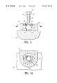
- FIG. 1 is an elevational view of an orthopedic implant assembly which embodies features of the invention.
- FIG. 2 is an exploded view, partially in section, of the orthopedic implant assembly shown in FIG. 1 .
- FIG. 3 is a cross section of the orthopedic implant assembly shown in FIG. 1 taken along lines 3 — 3 .
- FIG. 3A is a transverse cross section of the orthopedic implant assembly shown in FIG. 3 taken along lines 3 A— 3 A.
- FIG. 4 illustrates the orthopedic implant assembly shown in FIG. 3, as the securing element is being advanced into the patient's bone.
- FIG. 4A is a transverse cross section of the assembly shown in FIG. 4, taken along lines 4 A— 4 A.
- FIG. 5 illustrates the orthopedic implant assembly shown in FIG. 3, with the securing element advanced into the posterior section of the transverse passageway of the stabilizing element.
- FIG. 6 illustrates the orthopedic implant assembly shown in FIG. 3, with the securing element angularly disposed within the patient's bone.
- FIG. 7 is an exploded view, partially in section, of an orthopedic implant assembly having a securing element with a compressible head, which embodies features of the invention.
- FIG. 8 illustrates the orthopedic implant assembly shown in FIG. 7 as the securing element is being advanced into the patient's bone.
- FIGS. 9 is a transverse cross section of the assembly shown in FIG. 8, taken along lines 9 — 9 .
- FIG. 10 illustrates the orthopedic implant assembly shown in FIG. 7 with the securing element advanced into the posterior section of the transverse passageway of the stabilizing element.
- FIG. 11 is a transverse cross section of the assembly shown in FIG. 10, taken along lines 11 — 11 .
- FIG. 12 illustrates the orthopedic implant assembly shown in FIG. 7, with the securing element angularly disposed within the patient's bone.
- FIG. 13 is an exploded view, partially in section, of an orthopedic implant assembly having a deflectable stopping member, which embodies features of the invention.
- FIG. 14 illustrates the orthopedic implant assembly shown in FIG. 13 with the securing element advanced into the posterior section of the transverse passageway of the stabilizing element.
- FIGS. 15 is a plan view of the assembly shown in FIG. 14, taken along lines 15 — 15 .
- FIG. 1 illustrates one embodiment of the orthopedic implant assembly 10 of the invention, generally including a stabilizing element 11 , with a biased stopping member 12 in a bore 13 therein, and a securing element 14 , configured for securing to a patient's bone 15 .
- the biased stopping member comprises an annular collar, although a variety of suitable members may be used, as for example, one or more contractible fingers biased to extend into the transverse passageway (not shown).
- the bore 13 of the stabilizing element has a first opening 16 in an anterior surface of the stabilizing element, a second opening 17 in a posterior surface of the stabilizing element, a transverse passageway 18 extending therein, and a groove 21 in an anterior portion of the transverse passageway.
- Annular collar 12 defines a passageway 22 , and is configured to be seated within the groove 21 , and has a reversibly expandable inner and outer diameter.
- FIG. 3 illustrating the assembly shown in FIG. 1 partially in section taken along lines 3 — 3
- FIG. 3A illustrating a transverse cross sectional view of the assembly shown in FIG.
- the annular collar 12 is biased to an unexpanded outer diameter which is less than the diameter of the groove and greater than the diameter of the transverse passageway, so that the collar seats within the groove.
- the expanded outer diameter of the collar is less than the diameter of the groove, and the height of the collar is less than the height of the groove, so that the collar can be expanded therein.
- the securing element 14 has an elongated body 23 and an integral head 24 secured to one end of the body 23 .
- the securing element comprises a screw.
- the head of the securing element is configured to be posteriorly displaceable through the passageway 22 of the collar seated within the groove, from an anterior to a posterior surface of the collar, and retained within a posterior section 25 of the transverse passageway 18 between the posterior surface of the collar 12 and the second, i.e., posterior, opening 17 in the stabilizing element.
- the head of the securing element has a curved posterior surface 26 with a convex shape and with a smaller diameter than an anterior surface of the head.
- the curved posterior surface 26 has a minimum outer diameter which is smaller than the unexpanded inner diameter of the collar, and which is positionable within the passageway of the collar, to contact and expand the collar as the head is displaced posteriorly therein.
- FIGS. 3-5 illustrate the attachment of the assembly to the patient's bone.
- the stabilizing element is positioned against a surface of a bone 15 , and the posterior end of the body of the securing element 14 is placed within the stabilizing element transverse passageway.
- the head 24 of the securing element is posteriorly advanced within the passageway 22 of the collar 12 , thereby applying a radially expanding force against an inner surface of the collar to expand the inner diameter of the collar, as illustrated in FIG. 4 showing the expanded collar and the head of the securing element partially displaced through the collar passageway.
- Arrows in FIG. 4 illustrate the expansion of the collar as the head of the securing element is passed therethrough.
- FIG. 4A illustrates a transverse cross section of the assembly shown in FIG.
- the expanded inner diameter of the collar is therefore larger than the maximum diameter of the head of the securing element, to allow the head of the securing element to pass posteriorly through the collar.
- the head of the securing element is advanced posteriorly of the collar and into the posterior section 25 of the transverse passageway, so that the collar returns to the unexpanded configuration having an unexpanded inner diameter smaller than the maximum diameter of the head of the securing element, as illustrated in FIG. 5 .
- the flat anterior surface of the head of the securing element has a diameter which is larger than the unexpanded inner diameter of the collar, and the posterior surface of the collar is perpendicular to the longitudinal axis of the transverse passageway.
- a posterior portion of the transverse passageway is curved to conform to the curved posterior surface of the head, providing maximum contact between the securing element and the stabilizing element.
- the curved surfaces of the posterior portion of the transverse passageway and the posterior surface of the head have the same radius of curvature, and the diameter of the curved surface of the head is large enough so that the wall defining the transverse passageway contacts the head around the circumference of the curved posterior surface of the head, but is small enough so that the head can be displaced within the transverse passageway.
- the posterior section 25 of the transverse passageway is sufficiently longer than the head 24 of the securing element so that the head can be displaced anteriorly and posteriorly, and is thus longitudinally displaceable within the posterior section of the transverse passageway.
- the body of the securing element 23 has a smaller diameter than the diameter of the second opening 17 in the stabilizing element, and can be displaced from side to side, i.e., medial-lateral displacement, within the second opening 17 .
- the securing element is angularly displaceable within the transverse passageway posterior section 25 between the collar 12 and the second opening 17 in the stabilizing element, as illustrated in FIG. 6 .
- the securing element can thus be tilted within the transverse passageway at an angle relative to the transverse passageway longitudinal axis, to facilitate positioning the securing element at a desired location in the bone by advancing the body of the securing element within the bone at an angle relative to the surface of the bone.
- the securing element can be angularly displaced up to an angle of about 45°, preferably up to about 20° relative the longitudinal axis of the transverse passageway.
- the stopping member 12 is preferably elastically deformable, and formed of titanium, and superelastic or pseudoelastic materials such as NiTi alloys.
- the unexpanded inner diameter of the stopping member is about 0.1 to about 40 mm, preferably about 0.5 to about 20 mm, and is about 0.05 to about 20 mm, preferably about 0.1 to about 15 mm less than the maximum transverse dimension of the head of the securing element.
- the unexpanded outer diameter of the stopping member is about 0.2 to about 50 mm, preferably about 1.0 to about 30 mm.
- the expanded inner diameter of the stopping member is about 0.15 to about 50 mm, preferably about 0.75 to about 30 mm, and the expanded outer diameter of the stopping member is about 0.5 to about 60 mm, preferably about 1.5 to about 40 mm.
- the height of the stopping member is about 0.01 to about 5 mm, preferably about 0.05 to about 3 mm.
- FIGS. 7-12 illustrate another embodiment of the invention, generally comprising a securing element 30 , and a stabilizing element 31 similar to the stabilizing element in the embodiment illustrated in FIG. 1, except the stopping member is not seated within a groove in the transverse passageway 18 . Instead, a stopping member 32 is provided at an anterior section of the transverse passageway, which may be formed integrally with the stabilizing element or as a separate member secured thereto. In the embodiment illustrated in FIG. 7, the stopping member is a collar at the anterior end of the transverse passageway and defining the first opening 16 in the stabilizing element 31 .
- the securing element 30 has an elongated body 33 , and head 34 secured to one end of the body having a compressed configuration and an uncompressed configuration. In the embodiment illustrated in FIG.
- the head has a plurality of slots 35 defining circumferentially spaced members 36 having posterior ends secured to the body of the securing element.
- the circumferentially spaced members 36 have anterior ends radially moveable toward a longitudinal axis of the head to form the compressed configuration, having a diameter less than the inner diameter of the collar.
- FIG. 8 illustrates the head of the securing element in the compressed configuration within the passageway defined by the collar.
- FIG. 9 illustrates a transverse cross sectional view of the assembly shown in FIG. 8, taken along lines 9 — 9 .
- FIG. 10 illustrates the head of the securing element advanced posteriorly of the collar and into the posterior section of the transverse passageway, thereby returning the circumferentially spaced members 36 to the uncompressed configuration by release of the radially compressive force of the collar.
- FIG. 11 illustrates a transverse cross section of the assembly shown in FIG. 10, taken along lines 11 — 11 , with the first opening 16 shown in phantom.
- the securing element is angularly and longitudinally displaceable within the transverse passageway posterior section 25 , as discussed above with regard to the embodiment illustrated in FIG. 1, and as illustrated in FIG. 12 .
- FIGS. 13-15 illustrate another embodiment of the invention, generally comprising a stabilizing element 41 similar to the stabilizing element in the embodiment illustrated in FIG. 1, except with a deflectable stopping member 42 provided in an anterior section of the transverse passageway, which may be formed integrally with the stabilizing element or as a separate member secured thereto.
- the stopping member comprises a collar 42 having a plurality of slots 43 defining circumferentially spaced members 44 and a tapered or sloping anterior surface providing axial flexibility in a posterior direction, so that the collar deflects posteriorly when the head of the securing element is posteriorly displaced through the collar.
- the circumferentially spaced members 44 have a wedge shape and a height which tapers towards the central passageway 45 defined by the collar, which facilitates displacing the head of the securing element therethrough and reversibly enlarging the passageway 45 .
- the collar is integrally formed with the stabilizing element 41 at the anterior end of the transverse passageway, and defines the first opening 16 in the stabilizing element 41 .
- the securing element may be the same as, or similar to, the securing element 14 discussed above in connection with the embodiment illustrated in FIG. 1, and as illustrated in FIG. 13 .
- securing element 30 having head 34 with a compressed configuration and an uncompressed configuration, as discussed above in connection with the embodiment illustrated in FIG.
- FIG. 15 illustrates a plan view of the assembly shown in FIG. 14, taken along lines 15 — 15 , with the head of the securing element 14 partially in phantom.
- the angular and longitudinal displacement of the securing member in the posterior section 25 of the transverse passageway is as discussed above.
- the stabilizing element is preferably formed of a metal such as titanium or stainless steel.
- the length of the stabilizing element is typically about 7 to about 300 mm, preferably about 13 to about 200 mm, and the width of the stabilizing element is typically about 5 to about 50 mm, preferably about 10 to about 30 mm.
- the height of the stabilizing element is typically about 0.5 to about 10 mm, preferably about 1.0 to about 6.0 mm although the dimensions of the stabilizing element will vary depending on the application for which the assembly is to be used.
- the securing element is preferably formed of a metal, such as titanium or stainless steel.
- the head of the securing element is configured, as for example with a hexagonal opening, for releasable connection to a tool for advancing the securing element into the bone.
- the body of the securing element has a length of about 2 to about 50 mm, preferably about 5 to about 20 mm, and the head of the securing element has a length of about 0.05 to about 1.5 mm, preferably about 0.5 to about 1.0 mm.
- suitable securing elements may be used, which may be optimized for use in a particular orthopedic environment, as is well known in the art. For example, a high thread pitch may be used to limit screw back out from bone.
- the assembly of the invention is suitable for use in a variety of medical procedures, including securing fractured bone segments or vertebrae following disk removal.
- the stabilizing element comprises a plate, although other suitable elements such as rods may be used.
- the stabilizing element may be shaped to conform to the surface of the bone or bones to which it will be attached.
- a presently preferred embodiment of the stabilizing element comprises a plate with a concave posterior surface, and is configured for attaching to vertebrae.
Landscapes
- Health & Medical Sciences (AREA)
- Orthopedic Medicine & Surgery (AREA)
- Surgery (AREA)
- Life Sciences & Earth Sciences (AREA)
- Heart & Thoracic Surgery (AREA)
- Animal Behavior & Ethology (AREA)
- Engineering & Computer Science (AREA)
- Biomedical Technology (AREA)
- Neurology (AREA)
- Medical Informatics (AREA)
- Molecular Biology (AREA)
- Nuclear Medicine, Radiotherapy & Molecular Imaging (AREA)
- General Health & Medical Sciences (AREA)
- Public Health (AREA)
- Veterinary Medicine (AREA)
- Prostheses (AREA)
- Surgical Instruments (AREA)
- Orthopedics, Nursing, And Contraception (AREA)
Abstract
Description
Claims (28)
Priority Applications (21)
| Application Number | Priority Date | Filing Date | Title |
|---|---|---|---|
| US09/349,519 US6261291B1 (en) | 1999-07-08 | 1999-07-08 | Orthopedic implant assembly |
| EP00945170A EP1196103B1 (en) | 1999-07-08 | 2000-07-06 | Orthopedic implant assembly |
| CA2714070A CA2714070C (en) | 1999-07-08 | 2000-07-06 | Orthopedic implant assembly |
| PCT/US2000/018446 WO2001003592A1 (en) | 1999-07-08 | 2000-07-06 | Orthopedic implant assembly |
| AT00945170T ATE340537T1 (en) | 1999-07-08 | 2000-07-06 | ORTHOPEDIC IMPLANT ARRANGEMENT |
| EP06020151.4A EP1741399B1 (en) | 1999-07-08 | 2000-07-06 | Orthopedic implant assembly including stopping member and securing element |
| DE60030980T DE60030980T2 (en) | 1999-07-08 | 2000-07-06 | ORTHOPEDIC IMPLANT ASSEMBLY |
| CA002415096A CA2415096C (en) | 1999-07-08 | 2000-07-06 | Orthopedic implant assembly |
| ES06020150.6T ES2458937T3 (en) | 1999-07-08 | 2000-07-06 | Orthopedic implant unit comprising a locking element and a clamping element |
| CA2629225A CA2629225C (en) | 1999-07-08 | 2000-07-06 | Orthopedic implant assembly |
| EP06020150.6A EP1741398B1 (en) | 1999-07-08 | 2000-07-06 | Orthopedic implant assembly comprising stopping member and securing element |
| DK06020151.4T DK1741399T3 (en) | 1999-07-08 | 2000-07-06 | Orthopedic implant collection including abutment and securing element |
| CA2628346A CA2628346C (en) | 1999-07-08 | 2000-07-06 | Orthopedic implant assembly |
| ES00945170T ES2272300T3 (en) | 1999-07-08 | 2000-07-06 | ORTHOPEDIC IMPLANT UNIT. |
| AU59150/00A AU777576B2 (en) | 1999-07-08 | 2000-07-06 | Orthopedic implant assembly |
| DK00945170T DK1196103T3 (en) | 1999-07-08 | 2000-07-06 | Orthopedic implant system |
| ES06020151.4T ES2464167T3 (en) | 1999-07-08 | 2000-07-06 | Orthopedic implant unit comprising a locking element and a clamping element |
| JP2001508881A JP3650361B2 (en) | 1999-07-08 | 2000-07-06 | Orthopedic implant assembly |
| DK06020150.6T DK1741398T3 (en) | 1999-07-08 | 2000-07-06 | Orthopedic implant assembly including stop and securing element |
| US10/620,154 USRE43008E1 (en) | 1999-07-08 | 2003-07-15 | Orthopedic implant assembly |
| AU2005200257A AU2005200257B9 (en) | 1999-07-08 | 2005-01-21 | Orthopedic implant assembly |
Applications Claiming Priority (1)
| Application Number | Priority Date | Filing Date | Title |
|---|---|---|---|
| US09/349,519 US6261291B1 (en) | 1999-07-08 | 1999-07-08 | Orthopedic implant assembly |
Related Child Applications (1)
| Application Number | Title | Priority Date | Filing Date |
|---|---|---|---|
| US10/620,154 Reissue USRE43008E1 (en) | 1999-07-08 | 2003-07-15 | Orthopedic implant assembly |
Publications (1)
| Publication Number | Publication Date |
|---|---|
| US6261291B1 true US6261291B1 (en) | 2001-07-17 |
Family
ID=23372742
Family Applications (2)
| Application Number | Title | Priority Date | Filing Date |
|---|---|---|---|
| US09/349,519 Ceased US6261291B1 (en) | 1999-07-08 | 1999-07-08 | Orthopedic implant assembly |
| US10/620,154 Expired - Lifetime USRE43008E1 (en) | 1999-07-08 | 2003-07-15 | Orthopedic implant assembly |
Family Applications After (1)
| Application Number | Title | Priority Date | Filing Date |
|---|---|---|---|
| US10/620,154 Expired - Lifetime USRE43008E1 (en) | 1999-07-08 | 2003-07-15 | Orthopedic implant assembly |
Country Status (10)
| Country | Link |
|---|---|
| US (2) | US6261291B1 (en) |
| EP (3) | EP1741399B1 (en) |
| JP (1) | JP3650361B2 (en) |
| AT (1) | ATE340537T1 (en) |
| AU (2) | AU777576B2 (en) |
| CA (4) | CA2714070C (en) |
| DE (1) | DE60030980T2 (en) |
| DK (3) | DK1741399T3 (en) |
| ES (3) | ES2272300T3 (en) |
| WO (1) | WO2001003592A1 (en) |
Cited By (219)
| Publication number | Priority date | Publication date | Assignee | Title |
|---|---|---|---|---|
| US20020045898A1 (en) * | 2000-01-06 | 2002-04-18 | Spinal Concepts, Inc. | System and method for stabilizing the human spine with a bone plate |
| US6413259B1 (en) | 2000-12-14 | 2002-07-02 | Blackstone Medical, Inc | Bone plate assembly including a screw retaining member |
| US20020147499A1 (en) * | 2001-02-26 | 2002-10-10 | Shea Jeffrey J. | Locking systems for implants |
| US20030093082A1 (en) * | 2000-06-26 | 2003-05-15 | Stryker Spine | Bone screw retaining system |
| US20030135213A1 (en) * | 2001-04-06 | 2003-07-17 | Lehuec Jean-Charles | Anterior planting system and method |
| US6599290B2 (en) | 2001-04-17 | 2003-07-29 | Ebi, L.P. | Anterior cervical plating system and associated method |
| US6602255B1 (en) | 2000-06-26 | 2003-08-05 | Stryker Spine | Bone screw retaining system |
| US6620167B2 (en) * | 2001-10-17 | 2003-09-16 | Ricahrd J. Deslauriers | Orthopedic screw having driver-locking head |
| US20030187443A1 (en) * | 2002-03-27 | 2003-10-02 | Carl Lauryssen | Anterior bone plate system and method of use |
| US6669700B1 (en) | 1997-05-15 | 2003-12-30 | Sdgi Holdings, Inc. | Anterior cervical plating system |
| US6679883B2 (en) | 2001-10-31 | 2004-01-20 | Ortho Development Corporation | Cervical plate for stabilizing the human spine |
| US20040015169A1 (en) * | 2002-07-16 | 2004-01-22 | Larry Gause | Bone plate fastener retaining mechanisms and methods |
| WO2004006802A2 (en) * | 2002-07-16 | 2004-01-22 | Sdgi Holdings, Inc. | Plating system for stabilizing a bony segment |
| US20040034352A1 (en) * | 2002-08-16 | 2004-02-19 | Needham Dusty Anna | Systems, instrumentation and techniques for retaining fasteners relative to a bone plate |
| US20040087951A1 (en) * | 2002-11-04 | 2004-05-06 | Khalili Farid Bruce | Fastener retention system |
| US20040127899A1 (en) * | 2002-12-31 | 2004-07-01 | Konieczynski David D. | Bone plate and screw system allowing bi-directional attachment |
| US20040127904A1 (en) * | 2002-12-31 | 2004-07-01 | Konieczynski David D. | Bone plate and resilient screw system allowing bi-directional assembly |
| US20040127896A1 (en) * | 2002-10-28 | 2004-07-01 | Alan Lombardo | Bone plate assembly provided with screw locking mechanisms |
| US20040127900A1 (en) * | 2002-12-31 | 2004-07-01 | Konieczynski David D. | Resilient bone plate and screw system allowing bi-directional assembly |
| US20040133205A1 (en) * | 2002-06-24 | 2004-07-08 | Jeffrey Thramann | Cervical plate |
| US20040158252A1 (en) * | 2003-01-23 | 2004-08-12 | Stryker Trauma Gmbh | Implant for osteosynthesis |
| US20040204716A1 (en) * | 2003-04-09 | 2004-10-14 | Jonathan Fanger | Drill guide with alignment feature |
| US20040204712A1 (en) * | 2003-04-09 | 2004-10-14 | Eric Kolb | Bone fixation plates |
| US20040210221A1 (en) * | 2000-10-25 | 2004-10-21 | Jeffrey Kozak | Anterior lumbar plate and method |
| US20040230192A1 (en) * | 2001-07-20 | 2004-11-18 | Henry Graf | Intervertebral linking device |
| US20050010219A1 (en) * | 2003-07-07 | 2005-01-13 | Dalton Brain E. | Bone fixation assembly and method of securement |
| US20050010217A1 (en) * | 2003-07-07 | 2005-01-13 | Dalton Brian E. | Spinal stabilization implant and method of application |
| US20050027296A1 (en) * | 2002-06-24 | 2005-02-03 | Jeffrey Thramann | Cervical plate with backout protection |
| US20050043736A1 (en) * | 2001-12-24 | 2005-02-24 | Claude Mathieu | Device for osteosynthesis |
| US20050049593A1 (en) * | 2003-09-03 | 2005-03-03 | Duong Lan Anh Nguyen | Bone plate with captive clips |
| US20050059970A1 (en) * | 2003-09-17 | 2005-03-17 | Eric Kolb | Bone fixation systems |
| US20050071008A1 (en) * | 2003-09-30 | 2005-03-31 | Kirschman David Louis | Spinal fusion system and method for fusing spinal bones |
| FR2861980A1 (en) * | 2003-11-07 | 2005-05-13 | Euros Sa | Implant system for spinal vertebrae has locking element with surfaces able to engage with anchoring screw threads |
| EP1561429A1 (en) * | 2004-02-04 | 2005-08-10 | Bone and Joint Research S.A. | Fastener having a deformable head |
| US20050187553A1 (en) * | 2001-08-24 | 2005-08-25 | Grabowski John J. | Bone fixation device |
| US20050192580A1 (en) * | 2004-02-26 | 2005-09-01 | Dalton Brian E. | Polyaxial locking screw plate assembly |
| US20050228386A1 (en) * | 2004-04-08 | 2005-10-13 | Tara Ziolo | Bone fixation device |
| US20050283152A1 (en) * | 2004-06-17 | 2005-12-22 | Lindemann Gary S | Method and apparatus for retaining screws in a plate |
| US20060030850A1 (en) * | 2004-07-23 | 2006-02-09 | Keegan Thomas E | Methods and apparatuses for percutaneous implant delivery |
| US20060036250A1 (en) * | 2004-08-12 | 2006-02-16 | Lange Eric C | Antero-lateral plating systems for spinal stabilization |
| US20060079901A1 (en) * | 2003-09-03 | 2006-04-13 | Ryan Christopher J | Translatable carriage fixation system |
| WO2006047581A2 (en) * | 2004-02-26 | 2006-05-04 | Pioneer Laboratories, Inc. | Bone plate system and methods |
| US20060106387A1 (en) * | 2004-11-16 | 2006-05-18 | Depuy Spine, Inc. | Spinal plate system and method of use |
| US20060122604A1 (en) * | 2004-12-08 | 2006-06-08 | Depuy Spine, Inc. | Locking bone screw and spinal plate system |
| US20060122602A1 (en) * | 2004-12-08 | 2006-06-08 | Depuy Spine, Inc. | Hybrid spinal plates |
| US20060149251A1 (en) * | 2004-12-22 | 2006-07-06 | Tara Ziolo | Bone fixation system |
| US20060155285A1 (en) * | 2005-01-12 | 2006-07-13 | Kent Anderson | Anchor retaining mechanisms for bone plates |
| WO2006075069A1 (en) * | 2005-01-17 | 2006-07-20 | Didier Roux | Fixing system using captive screws |
| US20060161260A1 (en) * | 2003-12-23 | 2006-07-20 | Gareth Thomas | Total wrist prosthesis |
| US20060195089A1 (en) * | 2005-02-03 | 2006-08-31 | Lehuec Jean-Charles | Spinal plating and intervertebral support systems and methods |
| US20060200141A1 (en) * | 2005-02-18 | 2006-09-07 | Si Janna | Hindfoot nail |
| US20060229620A1 (en) * | 2005-03-03 | 2006-10-12 | Accin Corporation | Method and apparatus for providing a retainer for a bone stabilization device |
| US20060235533A1 (en) * | 2005-03-17 | 2006-10-19 | Jason Blain | Flanged interbody fusion device with hinge |
| US20060235400A1 (en) * | 2003-08-26 | 2006-10-19 | Rolf Schneider | Bone plate |
| US20060235399A1 (en) * | 2005-04-14 | 2006-10-19 | Sdgi Holdings, Inc. | Anti-backout mechanism for an implant fastener |
| US20060241615A1 (en) * | 2005-04-19 | 2006-10-26 | Sdgi Holdings, Inc. | Antero-lateral plating systems and methods for spinal stabilization |
| US20060241599A1 (en) * | 2003-06-27 | 2006-10-26 | Konieczynski David D | Polyaxial Bone Screw |
| US20060241612A1 (en) * | 2005-04-12 | 2006-10-26 | Robert J. Medoff | Bearing plate for use in fracture fixation having a spherical bearing hole with yielding expandability |
| US20060247639A1 (en) * | 2005-04-29 | 2006-11-02 | Sdgi Holdings, Inc. | Apparatus for retaining a bone anchor in a bone plate and method for use thereof |
| US20060287653A1 (en) * | 2005-06-15 | 2006-12-21 | Stryker Spine | Anterior cervical plate |
| US20070083207A1 (en) * | 2005-09-21 | 2007-04-12 | Tara Ziolo | Variable angle bone fixation assembly |
| US7204837B2 (en) | 2001-12-14 | 2007-04-17 | Paul Kamaljit S | Spinal plate assembly |
| US20070118125A1 (en) * | 2005-10-24 | 2007-05-24 | Orbay Jorge L | Bone fixation system and bone screws having anti-back out feature |
| US20070123885A1 (en) * | 2003-09-30 | 2007-05-31 | X-Spine Systems, Inc. | Screw locking mechanism and method |
| US20070185367A1 (en) * | 2006-02-02 | 2007-08-09 | Abdou M S | Treatment of Pain, Neurological Dysfunction and Neoplasms Using Radiation Delivery Catheters |
| US7255699B2 (en) | 2001-12-14 | 2007-08-14 | Paul Kamaljit S | Spinal plate assembly |
| US7278997B1 (en) | 2003-03-07 | 2007-10-09 | Theken Spine, Llc | Instrument guide and implant holder |
| US20070270880A1 (en) * | 2006-04-28 | 2007-11-22 | Lindemann Gary S | Bone screw revision tools and methods of use |
| US20070288025A1 (en) * | 2004-10-08 | 2007-12-13 | Andrea Peukert | Bone Screw |
| US7309340B2 (en) | 2003-06-20 | 2007-12-18 | Medicinelodge, Inc. | Method and apparatus for bone plating |
| US20080021476A1 (en) * | 2003-09-30 | 2008-01-24 | X-Spine Systems, Inc. | Spinal fusion system utilizing an implant plate having at least one integral lock and ratchet lock |
| US20080051786A1 (en) * | 2006-04-03 | 2008-02-28 | Acumed Llc | Bone plates with hybrid apertures |
| US7341591B2 (en) | 2003-01-30 | 2008-03-11 | Depuy Spine, Inc. | Anterior buttress staple |
| US20080086131A1 (en) * | 2006-10-06 | 2008-04-10 | Depuy Spine, Inc. | Bone screw fixation |
| US20080234751A1 (en) * | 2007-01-31 | 2008-09-25 | Mcclintock Larry E | Anterior vertebral plate with closed thread screw |
| US20080243192A1 (en) * | 2007-03-27 | 2008-10-02 | Depuy Spine, Inc. | Passive Screw Locking Mechanism |
| US20080249569A1 (en) * | 2007-04-03 | 2008-10-09 | Warsaw Orthopedic, Inc. | Implant Face Plates |
| US20080249625A1 (en) * | 2007-04-03 | 2008-10-09 | Warsaw Orthopedic, Inc. | Composite Interbody Spacer |
| US20080249575A1 (en) * | 2007-04-03 | 2008-10-09 | Warsaw Orthopedic, Inc. | Anchor Member Locking Features |
| US20080269809A1 (en) * | 2007-03-26 | 2008-10-30 | Laszlo Garamszegi | Bottom-loading pedicle screw assembly |
| US20090131988A1 (en) * | 2007-11-09 | 2009-05-21 | Stryker Spine | Cervical plate with a feedback device for selective association with bone screw blocking mechanism |
| US20090177239A1 (en) * | 2007-08-06 | 2009-07-09 | Michael Castro | Cervical plate instrument kit |
| US20090192553A1 (en) * | 2008-01-25 | 2009-07-30 | Depuy Spine, Inc. | Anti-backout mechanism |
| US20090281571A1 (en) * | 2008-05-08 | 2009-11-12 | Aesculap Implant Systems, Inc. | Minimally invasive spinal stabilization system |
| US20090306787A1 (en) * | 2006-04-04 | 2009-12-10 | Paul Charles Crabtree | Trial coupler systems and methods |
| US7655028B2 (en) | 2003-09-30 | 2010-02-02 | X-Spine Systems, Inc. | Spinal fusion system and method for fusing spinal bones |
| US7655009B2 (en) | 2003-12-01 | 2010-02-02 | Smith & Nephew, Inc. | Humeral nail |
| US20100076496A1 (en) * | 2004-01-26 | 2010-03-25 | Alberto Angel Fernandez | Variable Angle Locked Bone Fixation System |
| US7695501B2 (en) | 2003-08-28 | 2010-04-13 | Ellis Thomas J | Bone fixation system |
| US7704251B2 (en) | 2002-11-19 | 2010-04-27 | Acumed Llc | Adjustable bone plates |
| US7717945B2 (en) | 2002-07-22 | 2010-05-18 | Acumed Llc | Orthopedic systems |
| US20100145460A1 (en) * | 2008-11-07 | 2010-06-10 | Mcdonough William P | Zero-profile interbody spacer and coupled plate assembly |
| US7736380B2 (en) | 2004-12-21 | 2010-06-15 | Rhausler, Inc. | Cervical plate system |
| US7766911B1 (en) | 2002-07-05 | 2010-08-03 | Theken Spine, Llc | Fixed and variable locking fixation assembly |
| US7766947B2 (en) | 2001-10-31 | 2010-08-03 | Ortho Development Corporation | Cervical plate for stabilizing the human spine |
| US7776047B2 (en) | 2003-04-09 | 2010-08-17 | Depuy Spine, Inc. | Guide for spinal tools, implants, and devices |
| US20100217399A1 (en) * | 2009-02-22 | 2010-08-26 | Groh Gordon I | Base plate system for shoulder arthroplasty and method of using the same |
| US20100234897A1 (en) * | 2009-03-13 | 2010-09-16 | Lanx, Inc. | Spinal plate assemblies with backout protection cap and methods |
| US20100241174A1 (en) * | 2007-10-16 | 2010-09-23 | Robinson James C | Bone screw retaining and removal system |
| US20100256686A1 (en) * | 2009-04-06 | 2010-10-07 | Lanx, Inc. | Bone plate assemblies with backout protection and visual indicator |
| US20100268285A1 (en) * | 2001-10-18 | 2010-10-21 | Orthoip, Llc | Bone screw system and method for the fixation of bone fractures |
| US20110022096A1 (en) * | 2009-07-24 | 2011-01-27 | Spinal USA LLC | Bone plate system and methods of using the same |
| US20110022097A1 (en) * | 2009-07-24 | 2011-01-27 | Spinal USA LLC | Bone plate screw-blocking systems and methods |
| US7887595B1 (en) | 2005-12-05 | 2011-02-15 | Nuvasive, Inc. | Methods and apparatus for spinal fusion |
| US20110054544A1 (en) * | 2009-08-31 | 2011-03-03 | Warsaw Orthopedic, Inc. | System with integral locking mechanism |
| US7909860B2 (en) | 2003-09-03 | 2011-03-22 | Synthes Usa, Llc | Bone plate with captive clips |
| US7909848B2 (en) | 2003-06-27 | 2011-03-22 | Depuy Spine, Inc. | Tissue retractor and guide device |
| US7909829B2 (en) | 2003-06-27 | 2011-03-22 | Depuy Spine, Inc. | Tissue retractor and drill guide |
| US20110071575A1 (en) * | 2009-09-21 | 2011-03-24 | Jmea Corporation | Locking Securing Member |
| US20110106157A1 (en) * | 2009-10-30 | 2011-05-05 | Warsaw Orthropedic, Inc. | Self-Locking Interference Bone Screw for use with Spinal Implant |
| US7963982B2 (en) | 2007-07-16 | 2011-06-21 | X-Spine Systems, Inc. | Implant plate screw locking system and screw having a locking member |
| US20110172666A1 (en) * | 2010-01-08 | 2011-07-14 | Heilman Benjamin P | Variable angle locking screw |
| US8007523B2 (en) | 1997-08-04 | 2011-08-30 | Zimmer Spine, Inc. | System and method for stabilizing the human spine with a bone plate |
| US20110230885A1 (en) * | 2010-03-19 | 2011-09-22 | Nextremity Solutions, Llc | Dynamic bone plate |
| US20110313421A1 (en) * | 2010-06-17 | 2011-12-22 | Chris Sidebotham | Low profile medical locking plate and bone screw design for bone fractures |
| FR2963396A1 (en) * | 2010-07-29 | 2012-02-03 | Spineway | Screw head retaining device for fixing osteosynthesis plate in e.g. cervical spine, has flange cooperating with support zones, which are subjected to deformation during passage of flange, and act as stop for flange after engagement of screw |
| US8114162B1 (en) | 2006-08-09 | 2012-02-14 | Nuvasive, Inc. | Spinal fusion implant and related methods |
| US8172885B2 (en) | 2003-02-05 | 2012-05-08 | Pioneer Surgical Technology, Inc. | Bone plate system |
| US8177819B2 (en) | 2004-04-22 | 2012-05-15 | Acumed Llc | Expanded fixation of bones |
| US8246664B2 (en) | 2009-02-24 | 2012-08-21 | Osteomed Llc | Multiple bone fusion plate |
| US20120245632A1 (en) * | 2011-03-24 | 2012-09-27 | Intai Technology Corp. | Bone anchor |
| US8328856B1 (en) | 2008-10-14 | 2012-12-11 | Nuvasive, Inc. | Surgical fixation system and related methods |
| US20120323283A1 (en) * | 2009-04-23 | 2012-12-20 | Raymond Dunn | Bone fixture assembly |
| US8361126B2 (en) | 2007-07-03 | 2013-01-29 | Pioneer Surgical Technology, Inc. | Bone plate system |
| US8377139B2 (en) | 2010-06-17 | 2013-02-19 | Aesculap Implant Systems, Llc | Standalone interbody fusion device with locking and release mechanism |
| US20130053887A1 (en) * | 2011-08-26 | 2013-02-28 | Life Spine, Inc. | Bone Screw Retention in a Spinal Implant |
| US20130047971A1 (en) * | 2011-08-29 | 2013-02-28 | Hoyt Archery, Inc. | Limb bolt system |
| US8529608B2 (en) | 2009-04-28 | 2013-09-10 | Osteomed Llc | Bone plate with a transfixation screw hole |
| US8562656B2 (en) | 2010-10-15 | 2013-10-22 | Warsaw Orrthopedic, Inc. | Retaining mechanism |
| US8568417B2 (en) | 2009-12-18 | 2013-10-29 | Charles River Engineering Solutions And Technologies, Llc | Articulating tool and methods of using |
| US8574268B2 (en) | 2004-01-26 | 2013-11-05 | DePuy Synthes Product, LLC | Highly-versatile variable-angle bone plate system |
| US8574270B2 (en) | 2009-03-13 | 2013-11-05 | Spinal Simplicity Llc | Bone plate assembly with bone screw retention features |
| US8623019B2 (en) | 2007-07-03 | 2014-01-07 | Pioneer Surgical Technology, Inc. | Bone plate system |
| US20140114415A1 (en) * | 2012-10-19 | 2014-04-24 | Jeffrey Tyber | Orthopedic Systems for Spine and Tracking Control |
| US8709085B2 (en) | 2003-02-06 | 2014-04-29 | DePuy Synthes Products, LLC | Intervertebral implant |
| US8728129B2 (en) | 2011-01-07 | 2014-05-20 | Biomet Manufacturing, Llc | Variable angled locking screw |
| US8758346B2 (en) | 2009-09-14 | 2014-06-24 | DePuy Synthes Products, LLC | Variable angle compression plate |
| USD708747S1 (en) | 2006-09-25 | 2014-07-08 | Nuvasive, Inc. | Spinal fusion implant |
| US8771324B2 (en) | 2011-05-27 | 2014-07-08 | Globus Medical, Inc. | Securing fasteners |
| US8784027B2 (en) | 2010-09-14 | 2014-07-22 | Enduralock, Llc | Ratchet locking mechanism for threaded fastener |
| US8814915B2 (en) | 2009-03-13 | 2014-08-26 | Spinal Simplicity Llc | Dynamic vertebral column plate system |
| US8821553B2 (en) | 2003-09-30 | 2014-09-02 | X-Spine Systems, Inc. | Spinal fusion system utilizing an implant plate having at least one integral lock |
| US8828067B2 (en) | 2001-10-18 | 2014-09-09 | Orthoip, Llc | Bone screw system and method |
| US8858603B1 (en) | 2010-06-09 | 2014-10-14 | Choice Spine, L.P. | Cervical plate with screw retention clip |
| US8900277B2 (en) | 2004-02-26 | 2014-12-02 | Pioneer Surgical Technology, Inc. | Bone plate system |
| US8940030B1 (en) | 2011-01-28 | 2015-01-27 | Nuvasive, Inc. | Spinal fixation system and related methods |
| US8974504B2 (en) | 2012-05-10 | 2015-03-10 | Spinal Simplicity Llc | Dynamic bone fracture plates |
| US9005295B2 (en) | 2007-11-16 | 2015-04-14 | DePuy Synthes Products, LLC | Low profile intervertebral implant |
| US9039775B2 (en) | 2003-03-31 | 2015-05-26 | DePuy Synthes Products, Inc. | Spinal fixation plates |
| US9060809B2 (en) | 2001-10-18 | 2015-06-23 | Orthoip, Llc | Lagwire system and method for the fixation of bone fractures |
| US9060813B1 (en) | 2008-02-29 | 2015-06-23 | Nuvasive, Inc. | Surgical fixation system and related methods |
| US9078706B2 (en) | 2003-09-30 | 2015-07-14 | X-Spine Systems, Inc. | Intervertebral fusion device utilizing multiple mobile uniaxial and bidirectional screw interface plates |
| USD734853S1 (en) | 2009-10-14 | 2015-07-21 | Nuvasive, Inc. | Bone plate |
| US9095444B2 (en) | 2009-07-24 | 2015-08-04 | Warsaw Orthopedic, Inc. | Implant with an interference fit fastener |
| US9101407B2 (en) | 2011-07-19 | 2015-08-11 | Howmedica Osteonics Corp. | Anterior cervical plate |
| US9198769B2 (en) | 2011-12-23 | 2015-12-01 | Pioneer Surgical Technology, Inc. | Bone anchor assembly, bone plate system, and method |
| US9220604B2 (en) | 2010-12-21 | 2015-12-29 | DePuy Synthes Products, Inc. | Intervertebral implants, systems, and methods of use |
| US9220547B2 (en) | 2009-03-27 | 2015-12-29 | Spinal Elements, Inc. | Flanged interbody fusion device |
| US9237910B2 (en) | 2012-01-26 | 2016-01-19 | Acute Innovations Llc | Clip for rib stabilization |
| US9241809B2 (en) | 2010-12-21 | 2016-01-26 | DePuy Synthes Products, Inc. | Intervertebral implants, systems, and methods of use |
| US20160081771A1 (en) * | 2003-05-21 | 2016-03-24 | Nobel Biocare Services Ag | Condensing skeletal implant that facilitate insertions |
| US9387013B1 (en) | 2011-03-01 | 2016-07-12 | Nuvasive, Inc. | Posterior cervical fixation system |
| US20160287297A1 (en) * | 2011-01-10 | 2016-10-06 | Ascension Orthopedics, Inc. | Bone Plate System for Repair of Proximal Humeral Fracture |
| US9572681B2 (en) | 2002-02-19 | 2017-02-21 | DePuy Synthes Products, Inc. | Intervertebral implant |
| US9615866B1 (en) | 2004-10-18 | 2017-04-11 | Nuvasive, Inc. | Surgical fixation system and related methods |
| US9655656B2 (en) * | 2015-01-20 | 2017-05-23 | Amendia, Inc. | Modular pedicle screw assembly with a snap tulip |
| US9657766B2 (en) | 2010-09-14 | 2017-05-23 | Enduralock, Llc | Tools and ratchet locking mechanisms for threaded fasteners |
| US9775657B2 (en) | 2011-09-30 | 2017-10-03 | Acute Innovations Llc | Bone fixation system with opposed mounting portions |
| US9782207B2 (en) | 2014-07-03 | 2017-10-10 | Amendia, Inc. | Bone anchor locking device |
| US9841046B2 (en) | 2015-04-17 | 2017-12-12 | Enduralock, Llc | Locking fastener with deflectable lock |
| US9867718B2 (en) | 2014-10-22 | 2018-01-16 | DePuy Synthes Products, Inc. | Intervertebral implants, systems, and methods of use |
| US9943341B2 (en) | 2013-07-16 | 2018-04-17 | K2M, Llc | Retention plate member for a spinal plate system |
| US9956015B2 (en) | 2014-07-03 | 2018-05-01 | Acumed Llc | Bone plate with movable joint |
| US9987052B2 (en) | 2015-02-24 | 2018-06-05 | X-Spine Systems, Inc. | Modular interspinous fixation system with threaded component |
| US10105169B2 (en) | 2015-11-13 | 2018-10-23 | Leith Medical LLC | Bone fixation systems, apparatuses, and methods with anti-back-out feature |
| US10125807B2 (en) | 2015-09-08 | 2018-11-13 | Enduralock, Llc | Locking mechanisms with deflectable washer members |
| US10201433B2 (en) | 2012-10-19 | 2019-02-12 | Tyber Medical Llc | System and method for correcting scoliosis |
| US10206720B2 (en) | 2014-09-03 | 2019-02-19 | Aesculap Implant Systems, Llc | Fastener, spinal interbody system including same and method |
| US10206722B2 (en) | 2008-04-25 | 2019-02-19 | Pioneer Surgical Technology, Inc. | Bone plate system |
| US10215217B2 (en) | 2015-04-17 | 2019-02-26 | Enduralock, Llc | Locking fastener with deflectable lock |
| US10231768B2 (en) | 2003-05-30 | 2019-03-19 | DePuy Synthes Products, Inc. | Methods for implanting bone plates |
| USD857894S1 (en) | 2007-08-20 | 2019-08-27 | Nuvasive, Inc. | Surgical fixation system |
| US20190357951A1 (en) * | 2018-05-22 | 2019-11-28 | Subluxation Safe Asset, LP | Staple and plate hard tissue fixation |
| US10512548B2 (en) | 2006-02-27 | 2019-12-24 | DePuy Synthes Products, Inc. | Intervertebral implant with fixation geometry |
| US10543107B2 (en) | 2009-12-07 | 2020-01-28 | Samy Abdou | Devices and methods for minimally invasive spinal stabilization and instrumentation |
| US10548740B1 (en) | 2016-10-25 | 2020-02-04 | Samy Abdou | Devices and methods for vertebral bone realignment |
| US10575961B1 (en) | 2011-09-23 | 2020-03-03 | Samy Abdou | Spinal fixation devices and methods of use |
| US10610333B2 (en) | 2014-08-29 | 2020-04-07 | Nobel Biocare Services Ag | Restoration dental implant system and method |
| US10624686B2 (en) | 2016-09-08 | 2020-04-21 | DePuy Synthes Products, Inc. | Variable angel bone plate |
| US10695105B2 (en) | 2012-08-28 | 2020-06-30 | Samy Abdou | Spinal fixation devices and methods of use |
| US10758361B2 (en) | 2015-01-27 | 2020-09-01 | Spinal Elements, Inc. | Facet joint implant |
| US10772665B2 (en) | 2018-03-29 | 2020-09-15 | DePuy Synthes Products, Inc. | Locking structures for affixing bone anchors to a bone plate, and related systems and methods |
| US10801540B2 (en) | 2015-04-17 | 2020-10-13 | Enduralock, Llc | Locking mechanisms with deflectable lock member |
| US10820930B2 (en) | 2016-09-08 | 2020-11-03 | DePuy Synthes Products, Inc. | Variable angle bone plate |
| US10857003B1 (en) | 2015-10-14 | 2020-12-08 | Samy Abdou | Devices and methods for vertebral stabilization |
| US10864081B2 (en) | 2012-10-19 | 2020-12-15 | Tyber Medical, LLC | Wedge osteotomy device and method of use |
| US20200405358A1 (en) * | 2019-06-30 | 2020-12-31 | Innovasis, Inc. | Bone plate |
| US10905476B2 (en) | 2016-09-08 | 2021-02-02 | DePuy Synthes Products, Inc. | Variable angle bone plate |
| US10918498B2 (en) | 2004-11-24 | 2021-02-16 | Samy Abdou | Devices and methods for inter-vertebral orthopedic device placement |
| US10925651B2 (en) | 2018-12-21 | 2021-02-23 | DePuy Synthes Products, Inc. | Implant having locking holes with collection cavity for shavings |
| US10973648B1 (en) | 2016-10-25 | 2021-04-13 | Samy Abdou | Devices and methods for vertebral bone realignment |
| US11000321B2 (en) | 2017-05-25 | 2021-05-11 | Altus Partners Llc | Secondary screw blocking mechanism |
| US11006982B2 (en) | 2012-02-22 | 2021-05-18 | Samy Abdou | Spinous process fixation devices and methods of use |
| US11013541B2 (en) | 2018-04-30 | 2021-05-25 | DePuy Synthes Products, Inc. | Threaded locking structures for affixing bone anchors to a bone plate, and related systems and methods |
| US11026727B2 (en) | 2018-03-20 | 2021-06-08 | DePuy Synthes Products, Inc. | Bone plate with form-fitting variable-angle locking hole |
| US11111950B2 (en) | 2019-04-01 | 2021-09-07 | Enduralock, Llc | Locking mechanisms with deflectable lock member |
| US11123117B1 (en) | 2011-11-01 | 2021-09-21 | Nuvasive, Inc. | Surgical fixation system and related methods |
| US11173040B2 (en) | 2012-10-22 | 2021-11-16 | Cogent Spine, LLC | Devices and methods for spinal stabilization and instrumentation |
| US11179248B2 (en) | 2018-10-02 | 2021-11-23 | Samy Abdou | Devices and methods for spinal implantation |
| US11259851B2 (en) | 2003-08-26 | 2022-03-01 | DePuy Synthes Products, Inc. | Bone plate |
| US11291484B2 (en) | 2004-01-26 | 2022-04-05 | DePuy Synthes Products, Inc. | Highly-versatile variable-angle bone plate system |
| US11304817B2 (en) | 2020-06-05 | 2022-04-19 | Neurostructures, Inc. | Expandable interbody spacer |
| US11382769B2 (en) | 2018-09-20 | 2022-07-12 | Spinal Elements, Inc. | Spinal implant device |
| US11382761B2 (en) | 2020-04-11 | 2022-07-12 | Neurostructures, Inc. | Expandable interbody spacer |
| US11717419B2 (en) | 2020-12-10 | 2023-08-08 | Neurostructures, Inc. | Expandable interbody spacer |
| US11744626B2 (en) | 2019-10-14 | 2023-09-05 | Leith Medical, LLC | Bone fixation system with fasteners and a removal tool for decoupling of the fasteners |
| US11857434B2 (en) | 2013-03-14 | 2024-01-02 | X-Spine Systems, Inc. | Spinal implant and assembly |
| US11877779B2 (en) | 2020-03-26 | 2024-01-23 | Xtant Medical Holdings, Inc. | Bone plate system |
| US11911284B2 (en) | 2020-11-19 | 2024-02-27 | Spinal Elements, Inc. | Curved expandable interbody devices and deployment tools |
Families Citing this family (12)
| Publication number | Priority date | Publication date | Assignee | Title |
|---|---|---|---|---|
| FR2827150B1 (en) * | 2001-07-13 | 2004-06-18 | Ldr Medical | SELF-RETENTIVE FIXING DEVICE |
| DE202005021309U1 (en) * | 2005-07-20 | 2007-08-16 | Prevôt, Bertrand, Dr. med. | trochanter plate |
| WO2008098728A2 (en) * | 2007-02-12 | 2008-08-21 | Stryker Trauma Gmbh | Fixation device |
| US8734494B2 (en) | 2007-04-19 | 2014-05-27 | Stryker Trauma Gmbh | Hip fracture device with static locking mechanism allowing compression |
| FR2916956B1 (en) | 2007-06-08 | 2012-12-14 | Ldr Medical | INTERSOMATIC CAGE, INTERVERTEBRAL PROSTHESIS, ANCHORING DEVICE AND IMPLANTATION INSTRUMENTATION |
| FR2924015A1 (en) * | 2007-11-26 | 2009-05-29 | Spineway Soc Par Actions Simpl | Screw head holding system for e.g. osteosynthesis plate in cervical backbone, has hole and screw head presenting complementary holding shapes after placing and locking screw in support, where hole presents arrangements formed by slit |
| WO2010070154A1 (en) * | 2008-12-18 | 2010-06-24 | Surgival Co., S.A. | Locking device in screw-retained plates for medical use |
| CA2763265A1 (en) | 2009-05-26 | 2010-12-02 | Synthes Usa, Llc | Variable angle screw plate systems |
| US9055983B1 (en) * | 2014-04-24 | 2015-06-16 | Amendia, Inc. | Self-locking bone screw receiver |
| CN109330672B (en) | 2018-12-11 | 2024-04-12 | 北京爱康宜诚医疗器材有限公司 | Locking steel plate and locking steel plate assembly with same |
| EP4055287A4 (en) * | 2019-11-07 | 2023-07-12 | Fresenius Medical Care Deutschland GmbH | Fall-proof component for screw, fall-proof screw assembly, fall-proof screw-nut assembly and corresponding part, combination structure and assembly |
| KR102399608B1 (en) * | 2020-04-03 | 2022-05-19 | 주식회사 모레컴퍼니 | Bone fixing apparatus |
Citations (34)
| Publication number | Priority date | Publication date | Assignee | Title |
|---|---|---|---|---|
| US3350103A (en) | 1965-08-02 | 1967-10-31 | Ventura Tool Company | Seal ring holding device |
| US3863959A (en) | 1972-03-07 | 1975-02-04 | Kurt Karl Blaschke | Pipe connection |
| US4017946A (en) | 1976-03-01 | 1977-04-19 | Alta Engineering, Inc. | Lock screw for rigging connector or the like |
| US4280742A (en) | 1978-09-21 | 1981-07-28 | Smith International, Inc. | Wall contacting tool |
| US4488543A (en) * | 1982-01-19 | 1984-12-18 | Tornier S.A. France | Device for osteosynthesis of fractures of the extremities of the femur |
| US4662461A (en) | 1980-09-15 | 1987-05-05 | Garrett William R | Fixed-contact stabilizer |
| US4696290A (en) | 1983-12-16 | 1987-09-29 | Acromed Corporation | Apparatus for straightening spinal columns |
| US5054347A (en) | 1988-08-19 | 1991-10-08 | Mate Punch & Die Co. | Punch assembly with improved disassembly features |
| US5169597A (en) | 1989-12-21 | 1992-12-08 | Davidson James A | Biocompatible low modulus titanium alloy for medical implants |
| US5275601A (en) | 1991-09-03 | 1994-01-04 | Synthes (U.S.A) | Self-locking resorbable screws and plates for internal fixation of bone fractures and tendon-to-bone attachment |
| US5364399A (en) | 1993-02-05 | 1994-11-15 | Danek Medical, Inc. | Anterior cervical plating system |
| US5372660A (en) | 1993-08-26 | 1994-12-13 | Smith & Nephew Richards, Inc. | Surface and near surface hardened medical implants |
| DE4409833A1 (en) | 1994-03-22 | 1995-10-05 | Biedermann Motech Gmbh | Stabilizing device, in particular for stabilizing the spine |
| US5509933A (en) | 1989-12-21 | 1996-04-23 | Smith & Nephew Richards, Inc. | Medical implants of hot worked, high strength, biocompatible, low modulus titanium alloys |
| US5520690A (en) | 1995-04-13 | 1996-05-28 | Errico; Joseph P. | Anterior spinal polyaxial locking screw plate assembly |
| US5534032A (en) | 1993-06-21 | 1996-07-09 | Zimmer, Inc. | Orthopaedic implant assembly |
| US5569251A (en) | 1993-07-16 | 1996-10-29 | Bhc Engineering, L.P. | Implant device and method of installing |
| US5578034A (en) | 1995-06-07 | 1996-11-26 | Danek Medical, Inc. | Apparatus for preventing screw backout in a bone plate fixation system |
| US5601553A (en) | 1994-10-03 | 1997-02-11 | Synthes (U.S.A.) | Locking plate and bone screw |
| DE19545612A1 (en) | 1995-12-07 | 1997-06-12 | Aesculap Ag | Orthopedic retention system |
| US5735853A (en) | 1994-06-17 | 1998-04-07 | Olerud; Sven | Bone screw for osteosynthesis |
| WO1998017188A1 (en) | 1996-10-24 | 1998-04-30 | Spinal Concepts, Inc. | Method and apparatus for spinal fixation |
| US5785711A (en) | 1997-05-15 | 1998-07-28 | Third Millennium Engineering, Llc | Polyaxial pedicle screw having a through bar clamp locking mechanism |
| US5807396A (en) | 1995-12-22 | 1998-09-15 | Howmedica Leibinger Gmbh | Bone plate with conical holes |
| US5810819A (en) | 1997-05-15 | 1998-09-22 | Spinal Concepts, Inc. | Polyaxial pedicle screw having a compression locking rod gripping mechanism |
| WO1998048739A1 (en) | 1997-05-01 | 1998-11-05 | Spinal Concepts, Inc. | Multi-variable height fusion device |
| US5843082A (en) | 1996-05-31 | 1998-12-01 | Acromed Corporation | Cervical spine stabilization method and system |
| WO1999009904A1 (en) | 1997-08-26 | 1999-03-04 | Spinal Concepts, Inc. | Surgical cable system and method |
| US5879389A (en) | 1995-04-07 | 1999-03-09 | Koshino; Tomihisa | Medical substituting element for hard tissues and artificial joint |
| US5904683A (en) * | 1998-07-10 | 1999-05-18 | Sulzer Spine-Tech Inc. | Anterior cervical vertebral stabilizing device |
| US5928243A (en) | 1997-07-16 | 1999-07-27 | Spinal Concepts, Inc. | Pedicle probe and depth gage |
| US5935133A (en) | 1997-08-26 | 1999-08-10 | Spinal Concepts, Inc. | Surgical cable system and method |
| US6030389A (en) | 1997-08-04 | 2000-02-29 | Spinal Concepts, Inc. | System and method for stabilizing the human spine with a bone plate |
| US6045579A (en) | 1997-05-01 | 2000-04-04 | Spinal Concepts, Inc. | Adjustable height fusion device |
Family Cites Families (34)
| Publication number | Priority date | Publication date | Assignee | Title |
|---|---|---|---|---|
| US591798A (en) | 1897-10-12 | strauss | ||
| US2017247A (en) | 1934-10-17 | 1935-10-15 | George A Vis | Tool attachment |
| US2376089A (en) | 1943-11-11 | 1945-05-15 | Frederick L Savageau | Fastening device |
| US2782827A (en) | 1953-06-12 | 1957-02-26 | Rosan Joseph | Snap ring connection between threaded fastener and locking collar |
| US3062253A (en) | 1958-08-26 | 1962-11-06 | Waldes Kohinoor Inc | Bolt and shear sleeve with shear sleeve retracting means |
| US3561075A (en) | 1969-07-15 | 1971-02-09 | Motorola Inc | Threaded fastener captivating device |
| FR2188714A5 (en) | 1972-06-08 | 1974-01-18 | Gkn Screws Fasteners Ltd | |
| SE399579B (en) | 1975-04-24 | 1978-02-20 | Sandqvist Sune Allan | WAY TO ATTACH A TIGHT LAYER TO A SURFACE |
| US4288902A (en) | 1979-10-05 | 1981-09-15 | Franz Louis J | Method of forming a notched edge lock screw |
| US4380413A (en) | 1980-11-03 | 1983-04-19 | Illinois Tool Works Inc. | Load-distributive washer for use with compressible material |
| DE8410539U1 (en) | 1984-04-04 | 1985-05-02 | Marker Patentverwertungsgesellschaft mbH, Baar | Device on components that can be screwed onto an object |
| US4757661A (en) | 1986-03-17 | 1988-07-19 | Illinois Tool Works, Inc. | Washer with axial ribs |
| US4663910A (en) | 1986-03-17 | 1987-05-12 | Illinois Tool Works Inc. | Washer for roofing insulation |
| CH673087A5 (en) * | 1987-10-28 | 1990-02-15 | Sulzer Ag | |
| US5118235A (en) * | 1991-02-11 | 1992-06-02 | Illinois Tool Works Inc. | Washer with integral flap and fastening assembly combining fastener with such washer |
| CA2109907C (en) | 1992-11-25 | 2000-01-25 | Ronald A. Yapp | Osteosynthesis plate system |
| US5423826A (en) | 1993-02-05 | 1995-06-13 | Danek Medical, Inc. | Anterior cervical plate holder/drill guide and method of use |
| FR2712047B1 (en) * | 1993-11-05 | 1995-12-08 | Jeanson Jean Francois | Self-retention device for assembly and fixing elements such as screws, bolts and nuts. |
| US5601552A (en) | 1994-03-18 | 1997-02-11 | Sofamor, S.N.C. | Fixing device for a rigid transverse connection device between rods of a spinal osteosynthesis system |
| US5882350A (en) * | 1995-04-13 | 1999-03-16 | Fastenetix, Llc | Polyaxial pedicle screw having a threaded and tapered compression locking mechanism |
| US6780186B2 (en) * | 1995-04-13 | 2004-08-24 | Third Millennium Engineering Llc | Anterior cervical plate having polyaxial locking screws and sliding coupling elements |
| US5888205A (en) * | 1996-10-01 | 1999-03-30 | Kinamed, Inc. | Device for sealing acetabular cup holes |
| US5931838A (en) | 1997-01-28 | 1999-08-03 | Vito; Raymond P. | Fixation assembly for orthopedic applications |
| DE69838856T2 (en) | 1997-02-11 | 2008-12-11 | Warsaw Orthopedic, Inc., Warsaw | Plate for the anterior cervical spine with fixation system for one screw |
| JP4467647B2 (en) * | 1997-02-11 | 2010-05-26 | ウォーソー・オーソペディック・インコーポレーテッド | Bone plating system |
| US6017345A (en) * | 1997-05-09 | 2000-01-25 | Spinal Innovations, L.L.C. | Spinal fixation plate |
| WO1999000904A1 (en) | 1997-06-30 | 1999-01-07 | Maxim Integrated Products, Inc. | Interleaved differential analog-to-digital converter |
| US6010503A (en) * | 1998-04-03 | 2000-01-04 | Spinal Innovations, Llc | Locking mechanism |
| US6258089B1 (en) | 1998-05-19 | 2001-07-10 | Alphatec Manufacturing, Inc. | Anterior cervical plate and fixation system |
| FR2794963B1 (en) | 1999-06-17 | 2001-09-07 | Eurosurgical | ANTI-KICKBACK DEVICE FOR ORTHOPEDIC IMPLANT |
| US20060106387A1 (en) | 2004-11-16 | 2006-05-18 | Depuy Spine, Inc. | Spinal plate system and method of use |
| US7935137B2 (en) | 2004-12-08 | 2011-05-03 | Depuy Spine, Inc. | Locking bone screw and spinal plate system |
| US7931678B2 (en) | 2004-12-08 | 2011-04-26 | Depuy Spine, Inc. | Hybrid spinal plates |
| US20060122603A1 (en) | 2004-12-08 | 2006-06-08 | Depuy Spine, Inc. | Hybrid bone screw and plate systems |
-
1999
- 1999-07-08 US US09/349,519 patent/US6261291B1/en not_active Ceased
-
2000
- 2000-07-06 CA CA2714070A patent/CA2714070C/en not_active Expired - Lifetime
- 2000-07-06 WO PCT/US2000/018446 patent/WO2001003592A1/en active IP Right Grant
- 2000-07-06 ES ES00945170T patent/ES2272300T3/en not_active Expired - Lifetime
- 2000-07-06 AU AU59150/00A patent/AU777576B2/en not_active Expired
- 2000-07-06 ES ES06020151.4T patent/ES2464167T3/en not_active Expired - Lifetime
- 2000-07-06 CA CA2629225A patent/CA2629225C/en not_active Expired - Lifetime
- 2000-07-06 ES ES06020150.6T patent/ES2458937T3/en not_active Expired - Lifetime
- 2000-07-06 DK DK06020151.4T patent/DK1741399T3/en active
- 2000-07-06 EP EP06020151.4A patent/EP1741399B1/en not_active Expired - Lifetime
- 2000-07-06 JP JP2001508881A patent/JP3650361B2/en not_active Expired - Lifetime
- 2000-07-06 DK DK06020150.6T patent/DK1741398T3/en active
- 2000-07-06 DK DK00945170T patent/DK1196103T3/en active
- 2000-07-06 CA CA002415096A patent/CA2415096C/en not_active Expired - Lifetime
- 2000-07-06 EP EP06020150.6A patent/EP1741398B1/en not_active Expired - Lifetime
- 2000-07-06 EP EP00945170A patent/EP1196103B1/en not_active Expired - Lifetime
- 2000-07-06 CA CA2628346A patent/CA2628346C/en not_active Expired - Lifetime
- 2000-07-06 AT AT00945170T patent/ATE340537T1/en not_active IP Right Cessation
- 2000-07-06 DE DE60030980T patent/DE60030980T2/en not_active Expired - Lifetime
-
2003
- 2003-07-15 US US10/620,154 patent/USRE43008E1/en not_active Expired - Lifetime
-
2005
- 2005-01-21 AU AU2005200257A patent/AU2005200257B9/en not_active Expired
Patent Citations (45)
| Publication number | Priority date | Publication date | Assignee | Title |
|---|---|---|---|---|
| US3350103A (en) | 1965-08-02 | 1967-10-31 | Ventura Tool Company | Seal ring holding device |
| US3863959A (en) | 1972-03-07 | 1975-02-04 | Kurt Karl Blaschke | Pipe connection |
| US4017946A (en) | 1976-03-01 | 1977-04-19 | Alta Engineering, Inc. | Lock screw for rigging connector or the like |
| US4280742A (en) | 1978-09-21 | 1981-07-28 | Smith International, Inc. | Wall contacting tool |
| US4662461A (en) | 1980-09-15 | 1987-05-05 | Garrett William R | Fixed-contact stabilizer |
| US4488543A (en) * | 1982-01-19 | 1984-12-18 | Tornier S.A. France | Device for osteosynthesis of fractures of the extremities of the femur |
| US4696290A (en) | 1983-12-16 | 1987-09-29 | Acromed Corporation | Apparatus for straightening spinal columns |
| US5054347A (en) | 1988-08-19 | 1991-10-08 | Mate Punch & Die Co. | Punch assembly with improved disassembly features |
| US5169597A (en) | 1989-12-21 | 1992-12-08 | Davidson James A | Biocompatible low modulus titanium alloy for medical implants |
| US5509933A (en) | 1989-12-21 | 1996-04-23 | Smith & Nephew Richards, Inc. | Medical implants of hot worked, high strength, biocompatible, low modulus titanium alloys |
| US5275601A (en) | 1991-09-03 | 1994-01-04 | Synthes (U.S.A) | Self-locking resorbable screws and plates for internal fixation of bone fractures and tendon-to-bone attachment |
| US5364399A (en) | 1993-02-05 | 1994-11-15 | Danek Medical, Inc. | Anterior cervical plating system |
| US5534032A (en) | 1993-06-21 | 1996-07-09 | Zimmer, Inc. | Orthopaedic implant assembly |
| US5569251A (en) | 1993-07-16 | 1996-10-29 | Bhc Engineering, L.P. | Implant device and method of installing |
| US5372660A (en) | 1993-08-26 | 1994-12-13 | Smith & Nephew Richards, Inc. | Surface and near surface hardened medical implants |
| DE4409833A1 (en) | 1994-03-22 | 1995-10-05 | Biedermann Motech Gmbh | Stabilizing device, in particular for stabilizing the spine |
| US5735853A (en) | 1994-06-17 | 1998-04-07 | Olerud; Sven | Bone screw for osteosynthesis |
| US5601553A (en) | 1994-10-03 | 1997-02-11 | Synthes (U.S.A.) | Locking plate and bone screw |
| US5879389A (en) | 1995-04-07 | 1999-03-09 | Koshino; Tomihisa | Medical substituting element for hard tissues and artificial joint |
| US5725588A (en) | 1995-04-13 | 1998-03-10 | Fastenetix, Llc | Acetabular cup having polyaxial locking screws |
| US5876402A (en) | 1995-04-13 | 1999-03-02 | Errico; Joseph P. | Anterior spinal polyaxial locking screw plate assembly having recessed retaining rings |
| US5643265A (en) | 1995-04-13 | 1997-07-01 | Fastenetix, L.L.C. | Dynamic compression polyaxial locking screw plate assembly |
| US5607426A (en) | 1995-04-13 | 1997-03-04 | Fastenletix, L.L.C. | Threaded polyaxial locking screw plate assembly |
| US5520690A (en) | 1995-04-13 | 1996-05-28 | Errico; Joseph P. | Anterior spinal polyaxial locking screw plate assembly |
| US5578034A (en) | 1995-06-07 | 1996-11-26 | Danek Medical, Inc. | Apparatus for preventing screw backout in a bone plate fixation system |
| US6117173A (en) | 1995-12-07 | 2000-09-12 | Aesculap Ag & Co., Kg | Orthopaedic fixing system |
| DE19545612A1 (en) | 1995-12-07 | 1997-06-12 | Aesculap Ag | Orthopedic retention system |
| US5807396A (en) | 1995-12-22 | 1998-09-15 | Howmedica Leibinger Gmbh | Bone plate with conical holes |
| US5843082A (en) | 1996-05-31 | 1998-12-01 | Acromed Corporation | Cervical spine stabilization method and system |
| WO1998017188A1 (en) | 1996-10-24 | 1998-04-30 | Spinal Concepts, Inc. | Method and apparatus for spinal fixation |
| US5989250A (en) | 1996-10-24 | 1999-11-23 | Spinal Concepts, Inc. | Method and apparatus for spinal fixation |
| WO1998048739A1 (en) | 1997-05-01 | 1998-11-05 | Spinal Concepts, Inc. | Multi-variable height fusion device |
| US6045579A (en) | 1997-05-01 | 2000-04-04 | Spinal Concepts, Inc. | Adjustable height fusion device |
| US5961518A (en) | 1997-05-15 | 1999-10-05 | Spinal Concepts, Inc. | Polyaxial pedicle screw having a through bar clamp locking mechanism |
| US5785711A (en) | 1997-05-15 | 1998-07-28 | Third Millennium Engineering, Llc | Polyaxial pedicle screw having a through bar clamp locking mechanism |
| US5997539A (en) | 1997-05-15 | 1999-12-07 | Spinal Concepts, Inc. | Polyaxial pedicle screw having a compression locking rod gripping mechanism |
| US6017344A (en) | 1997-05-15 | 2000-01-25 | Spinal Concepts, Inc. | Polyaxial pedicle screw having a through bar clamp locking mechanism |
| US5810819A (en) | 1997-05-15 | 1998-09-22 | Spinal Concepts, Inc. | Polyaxial pedicle screw having a compression locking rod gripping mechanism |
| US5928243A (en) | 1997-07-16 | 1999-07-27 | Spinal Concepts, Inc. | Pedicle probe and depth gage |
| US6030389A (en) | 1997-08-04 | 2000-02-29 | Spinal Concepts, Inc. | System and method for stabilizing the human spine with a bone plate |
| US5935133A (en) | 1997-08-26 | 1999-08-10 | Spinal Concepts, Inc. | Surgical cable system and method |
| US5964769A (en) | 1997-08-26 | 1999-10-12 | Spinal Concepts, Inc. | Surgical cable system and method |
| WO1999009904A1 (en) | 1997-08-26 | 1999-03-04 | Spinal Concepts, Inc. | Surgical cable system and method |
| US6053921A (en) | 1997-08-26 | 2000-04-25 | Spinal Concepts, Inc. | Surgical cable system and method |
| US5904683A (en) * | 1998-07-10 | 1999-05-18 | Sulzer Spine-Tech Inc. | Anterior cervical vertebral stabilizing device |
Cited By (529)
| Publication number | Priority date | Publication date | Assignee | Title |
|---|---|---|---|---|
| US8277493B2 (en) | 1997-05-15 | 2012-10-02 | Warsaw Orthopedic, Inc. | Anterior cervical plating system |
| US20060189990A1 (en) * | 1997-05-15 | 2006-08-24 | Farris Robert A | Anterior cervical plating system |
| US7001387B2 (en) | 1997-05-15 | 2006-02-21 | Sdgi Holdings, Inc. | Anterior cervical plating system |
| US20040097934A1 (en) * | 1997-05-15 | 2004-05-20 | Farris Robert A. | Anterior cervical plating system |
| US6669700B1 (en) | 1997-05-15 | 2003-12-30 | Sdgi Holdings, Inc. | Anterior cervical plating system |
| US8007523B2 (en) | 1997-08-04 | 2011-08-30 | Zimmer Spine, Inc. | System and method for stabilizing the human spine with a bone plate |
| US20020045898A1 (en) * | 2000-01-06 | 2002-04-18 | Spinal Concepts, Inc. | System and method for stabilizing the human spine with a bone plate |
| US8025677B2 (en) | 2000-01-06 | 2011-09-27 | Zimmer Spine, Inc. | System and method for stabilizing the human spine with a bone plate |
| US20040127897A1 (en) * | 2000-01-06 | 2004-07-01 | Jim Freid | System and method for stabilizing the human spine with a bone plate |
| US7611527B2 (en) | 2000-01-06 | 2009-11-03 | Zimmer Spine, Inc. | System and method for stabilizing the human spine with a bone plate |
| US6602255B1 (en) | 2000-06-26 | 2003-08-05 | Stryker Spine | Bone screw retaining system |
| US20050149027A1 (en) * | 2000-06-26 | 2005-07-07 | Stryker Spine | Bone screw retaining system |
| US20140243909A1 (en) * | 2000-06-26 | 2014-08-28 | Stryker Spine | Bone screw retaining system |
| US20030093082A1 (en) * | 2000-06-26 | 2003-05-15 | Stryker Spine | Bone screw retaining system |
| US8734496B2 (en) * | 2000-06-26 | 2014-05-27 | Stryker Spine | Bone screw retaining system |
| US8287550B2 (en) | 2000-06-26 | 2012-10-16 | Stryker Spine | Bone screw retaining system |
| US20130066379A1 (en) * | 2000-06-26 | 2013-03-14 | Stryker Spine | Bone screw retaining system |
| US20110152944A1 (en) * | 2000-06-26 | 2011-06-23 | Stryker Spine | Bone screw retaining system |
| US7887547B2 (en) * | 2000-06-26 | 2011-02-15 | Stryker Spine | Bone screw retaining system |
| US9186189B2 (en) * | 2000-06-26 | 2015-11-17 | Stryker Spine | Bone screw retaining system |
| US8617224B2 (en) | 2000-10-25 | 2013-12-31 | Warsaw Orthopedic, Inc. | Anterior lumbar plate and method |
| US8016863B2 (en) | 2000-10-25 | 2011-09-13 | Warsaw Orthopedic, Inc. | Anterior lumbar plate and method |
| US20040210221A1 (en) * | 2000-10-25 | 2004-10-21 | Jeffrey Kozak | Anterior lumbar plate and method |
| US6413259B1 (en) | 2000-12-14 | 2002-07-02 | Blackstone Medical, Inc | Bone plate assembly including a screw retaining member |
| US20020147499A1 (en) * | 2001-02-26 | 2002-10-10 | Shea Jeffrey J. | Locking systems for implants |
| US8388662B2 (en) | 2001-04-06 | 2013-03-05 | Warsaw Orthopedic, Inc | Anterior plating system and method |
| US7758616B2 (en) | 2001-04-06 | 2010-07-20 | Warsaw Orthopedic, Inc. | Anterior plating system and method |
| US20030135213A1 (en) * | 2001-04-06 | 2003-07-17 | Lehuec Jean-Charles | Anterior planting system and method |
| US6793658B2 (en) | 2001-04-06 | 2004-09-21 | Society De Fabrication De Material Orthopedique, S.A. | Anterior plating system and method |
| US20100228294A1 (en) * | 2001-04-06 | 2010-09-09 | Warsaw Othropedic.Inc. | Anterior plating system and method |
| US20050027293A1 (en) * | 2001-04-06 | 2005-02-03 | Lehuec Jean-Charles | Anterior plating system and method |
| US6884242B2 (en) | 2001-04-06 | 2005-04-26 | Society De Fabrication De Materiel Orthopedique, S.A. | Anterior plating system and method |
| US6599290B2 (en) | 2001-04-17 | 2003-07-29 | Ebi, L.P. | Anterior cervical plating system and associated method |
| US20040230192A1 (en) * | 2001-07-20 | 2004-11-18 | Henry Graf | Intervertebral linking device |
| US20050187553A1 (en) * | 2001-08-24 | 2005-08-25 | Grabowski John J. | Bone fixation device |
| US7833226B2 (en) * | 2001-08-24 | 2010-11-16 | Zimmer Spine, Inc. | Bone fixation device |
| US6620167B2 (en) * | 2001-10-17 | 2003-09-16 | Ricahrd J. Deslauriers | Orthopedic screw having driver-locking head |
| US8828067B2 (en) | 2001-10-18 | 2014-09-09 | Orthoip, Llc | Bone screw system and method |
| US20100268285A1 (en) * | 2001-10-18 | 2010-10-21 | Orthoip, Llc | Bone screw system and method for the fixation of bone fractures |
| US9028534B2 (en) | 2001-10-18 | 2015-05-12 | Orthoip, Llc | Bone screw system and method |
| US9060809B2 (en) | 2001-10-18 | 2015-06-23 | Orthoip, Llc | Lagwire system and method for the fixation of bone fractures |
| US7766947B2 (en) | 2001-10-31 | 2010-08-03 | Ortho Development Corporation | Cervical plate for stabilizing the human spine |
| US6679883B2 (en) | 2001-10-31 | 2004-01-20 | Ortho Development Corporation | Cervical plate for stabilizing the human spine |
| US8236033B2 (en) | 2001-12-14 | 2012-08-07 | Paul Kamaljit S | Spinal plate assembly |
| US8221476B2 (en) | 2001-12-14 | 2012-07-17 | Paul Kamaljit S | Spinal plate assembly |
| US7255699B2 (en) | 2001-12-14 | 2007-08-14 | Paul Kamaljit S | Spinal plate assembly |
| US20070288015A1 (en) * | 2001-12-14 | 2007-12-13 | Paul Kamaljit S | Spinal plate assembly |
| US20080033439A1 (en) * | 2001-12-14 | 2008-02-07 | Paul Kamaljit S | Spinal plate assembly |
| US7204837B2 (en) | 2001-12-14 | 2007-04-17 | Paul Kamaljit S | Spinal plate assembly |
| US20050043736A1 (en) * | 2001-12-24 | 2005-02-24 | Claude Mathieu | Device for osteosynthesis |
| US7682379B2 (en) * | 2001-12-24 | 2010-03-23 | Synthes Usa, Llc | Device for osteosynthesis |
| US10492922B2 (en) | 2002-02-19 | 2019-12-03 | DePuy Synthes Products, Inc. | Intervertebral implant |
| US9572681B2 (en) | 2002-02-19 | 2017-02-21 | DePuy Synthes Products, Inc. | Intervertebral implant |
| US20050182404A1 (en) * | 2002-03-27 | 2005-08-18 | Depuy Spine, Inc. | Anterior bone plate system and method of use |
| US8491643B2 (en) | 2002-03-27 | 2013-07-23 | Depuy Spine, Inc. | Anterior bone plate system and method of use |
| US20030187443A1 (en) * | 2002-03-27 | 2003-10-02 | Carl Lauryssen | Anterior bone plate system and method of use |
| EP1348390A3 (en) * | 2002-03-27 | 2004-03-03 | DePuy AcroMed, Inc. | Anterior bone plate system and method of use |
| US8652181B2 (en) | 2002-06-24 | 2014-02-18 | Lanx, Inc. | Cervical plate |
| US8778001B2 (en) | 2002-06-24 | 2014-07-15 | Lanx, Inc. | Cervical plate |
| US20040133205A1 (en) * | 2002-06-24 | 2004-07-08 | Jeffrey Thramann | Cervical plate |
| US7175623B2 (en) | 2002-06-24 | 2007-02-13 | Lanx, Llc | Cervical plate with backout protection |
| US20050027296A1 (en) * | 2002-06-24 | 2005-02-03 | Jeffrey Thramann | Cervical plate with backout protection |
| US7077843B2 (en) | 2002-06-24 | 2006-07-18 | Lanx, Llc | Cervical plate |
| US7766911B1 (en) | 2002-07-05 | 2010-08-03 | Theken Spine, Llc | Fixed and variable locking fixation assembly |
| US7780666B1 (en) | 2002-07-05 | 2010-08-24 | Theken Spine, Llc | Fixed and variable locking fixation assembly |
| US7785327B1 (en) | 2002-07-05 | 2010-08-31 | Theken Spine, Llc | Fixed and variable locking fixation assembly |
| US8070784B2 (en) | 2002-07-16 | 2011-12-06 | Warsaw Orthopedic, Inc. | Plating system for stabilizing a bony segment |
| US7004944B2 (en) | 2002-07-16 | 2006-02-28 | Sdgi Holdings, Inc. | Bone plate fastener retaining mechanisms and methods |
| US6989012B2 (en) | 2002-07-16 | 2006-01-24 | Sdgi Holdings, Inc. | Plating system for stabilizing a bony segment |
| US20040015169A1 (en) * | 2002-07-16 | 2004-01-22 | Larry Gause | Bone plate fastener retaining mechanisms and methods |
| AU2003254044B2 (en) * | 2002-07-16 | 2007-07-12 | Warsaw Orthopedic, Inc. | Plating system for stabilizing a bony segment |
| WO2004006802A2 (en) * | 2002-07-16 | 2004-01-22 | Sdgi Holdings, Inc. | Plating system for stabilizing a bony segment |
| US20040034356A1 (en) * | 2002-07-16 | 2004-02-19 | Lehuec Jean-Charles | Plating system for stabilizing a bony segment |
| WO2004006802A3 (en) * | 2002-07-16 | 2004-04-29 | Sdgi Holdings Inc | Plating system for stabilizing a bony segment |
| US20060074420A1 (en) * | 2002-07-16 | 2006-04-06 | Lehuec Jean-Charles | Plating system for stabilizing a bony segment |
| US8425574B2 (en) | 2002-07-22 | 2013-04-23 | Acumed, Llc | Bone fixation with a bone plate attached to a fastener assembly |
| US9308033B2 (en) | 2002-07-22 | 2016-04-12 | Acumed Llc | Adjustable bone plates |
| US10456180B2 (en) | 2002-07-22 | 2019-10-29 | Acumed Llc | Adjustable bone plates |
| US7717945B2 (en) | 2002-07-22 | 2010-05-18 | Acumed Llc | Orthopedic systems |
| US20040034352A1 (en) * | 2002-08-16 | 2004-02-19 | Needham Dusty Anna | Systems, instrumentation and techniques for retaining fasteners relative to a bone plate |
| US7060067B2 (en) | 2002-08-16 | 2006-06-13 | Sdgi Holdings, Inc. | Systems, instrumentation and techniques for retaining fasteners relative to a bone plate |
| US20080009870A1 (en) * | 2002-10-28 | 2008-01-10 | Alan Lombardo | Bone plate assembly provided with screw locking mechanisms |
| US7273481B2 (en) | 2002-10-28 | 2007-09-25 | Blackstone Medical, Inc. | Bone plate assembly provided with screw locking mechanisms |
| US9241749B2 (en) | 2002-10-28 | 2016-01-26 | Blackstone Medical, Inc. | Bone plate assembly provided with screw locking mechanisms |
| US20040127896A1 (en) * | 2002-10-28 | 2004-07-01 | Alan Lombardo | Bone plate assembly provided with screw locking mechanisms |
| US8439957B2 (en) | 2002-10-28 | 2013-05-14 | Blackstone Medical, Inc. | Bone plate assembly provided with screw locking mechanisms |
| US8075602B2 (en) | 2002-10-28 | 2011-12-13 | Blackstone Medical, Inc. | Bone plate assembly provided with screw locking mechanisms |
| US20040087951A1 (en) * | 2002-11-04 | 2004-05-06 | Khalili Farid Bruce | Fastener retention system |
| US7524325B2 (en) * | 2002-11-04 | 2009-04-28 | Farid Bruce Khalili | Fastener retention system |
| US7704251B2 (en) | 2002-11-19 | 2010-04-27 | Acumed Llc | Adjustable bone plates |
| US20050273105A1 (en) * | 2002-12-31 | 2005-12-08 | Depuy Spine, Inc. | Bone plate and screw system allowing bi-directional assembly |
| US20040127900A1 (en) * | 2002-12-31 | 2004-07-01 | Konieczynski David D. | Resilient bone plate and screw system allowing bi-directional assembly |
| US8747441B2 (en) | 2002-12-31 | 2014-06-10 | Depuy Spine, Inc. | Resilient bone plate and screw system allowing bi-directional assembly |
| US20040127899A1 (en) * | 2002-12-31 | 2004-07-01 | Konieczynski David D. | Bone plate and screw system allowing bi-directional attachment |
| US7914561B2 (en) | 2002-12-31 | 2011-03-29 | Depuy Spine, Inc. | Resilient bone plate and screw system allowing bi-directional assembly |
| US7048739B2 (en) | 2002-12-31 | 2006-05-23 | Depuy Spine, Inc. | Bone plate and resilient screw system allowing bi-directional assembly |
| US20060241616A1 (en) * | 2002-12-31 | 2006-10-26 | Depuy Spine, Inc. | Bone Plate and Resilient Screw System Allowing Bi-Directional Assembly |
| US7175624B2 (en) * | 2002-12-31 | 2007-02-13 | Depuy Spine, Inc. | Bone plate and screw system allowing bi-directional assembly |
| US20040127904A1 (en) * | 2002-12-31 | 2004-07-01 | Konieczynski David D. | Bone plate and resilient screw system allowing bi-directional assembly |
| US7651517B2 (en) | 2002-12-31 | 2010-01-26 | Depuy Acromed, Inc. | Bone plate and resilient screw system allowing bi-directional assembly |
| US9351774B2 (en) | 2002-12-31 | 2016-05-31 | DePuy Synthes Products, Inc. | Resilient bone plate and screw system allowing bi-directional assembly |
| US7981142B2 (en) | 2002-12-31 | 2011-07-19 | Depuy Spine, Inc. | Bone plate and screw system allowing bi-directional assembly |
| US7247157B2 (en) | 2003-01-23 | 2007-07-24 | Stryker Trauma Gmbh | Implant for osteosynthesis |
| US8241287B2 (en) | 2003-01-23 | 2012-08-14 | Stryker Trauma Gmbh | Implant for osteosynthesis |
| US20100191240A1 (en) * | 2003-01-23 | 2010-07-29 | Stryker Trauma Gmbh | Implant for osteosynthesis |
| US20040158252A1 (en) * | 2003-01-23 | 2004-08-12 | Stryker Trauma Gmbh | Implant for osteosynthesis |
| US8672940B2 (en) | 2003-01-23 | 2014-03-18 | Stryker Trauma Gmbh | Implant for osteosynthesis |
| US7341591B2 (en) | 2003-01-30 | 2008-03-11 | Depuy Spine, Inc. | Anterior buttress staple |
| US8172885B2 (en) | 2003-02-05 | 2012-05-08 | Pioneer Surgical Technology, Inc. | Bone plate system |
| US10064740B2 (en) | 2003-02-06 | 2018-09-04 | DePuy Synthes Products, LLC | Intervertebral implant |
| US8764831B2 (en) | 2003-02-06 | 2014-07-01 | DePuy Synthes Products, LLC | Intervertebral implant |
| US8709085B2 (en) | 2003-02-06 | 2014-04-29 | DePuy Synthes Products, LLC | Intervertebral implant |
| US8715354B2 (en) | 2003-02-06 | 2014-05-06 | DePuy Synthes Products, LLC | Intervertebral implant |
| US9463097B2 (en) | 2003-02-06 | 2016-10-11 | DePuy Synthes Products, Inc. | Intervertebral implant |
| US10660765B2 (en) | 2003-02-06 | 2020-05-26 | DePuy Synthes Products, Inc. | Intervertebral implant |
| US7278997B1 (en) | 2003-03-07 | 2007-10-09 | Theken Spine, Llc | Instrument guide and implant holder |
| US9039775B2 (en) | 2003-03-31 | 2015-05-26 | DePuy Synthes Products, Inc. | Spinal fixation plates |
| US9320549B2 (en) | 2003-03-31 | 2016-04-26 | DePuy Synthes Products, Inc. | Spinal fixation plates |
| US20040204716A1 (en) * | 2003-04-09 | 2004-10-14 | Jonathan Fanger | Drill guide with alignment feature |
| US7935123B2 (en) | 2003-04-09 | 2011-05-03 | Depuy Acromed, Inc. | Drill guide with alignment feature |
| US7776047B2 (en) | 2003-04-09 | 2010-08-17 | Depuy Spine, Inc. | Guide for spinal tools, implants, and devices |
| US8394107B2 (en) | 2003-04-09 | 2013-03-12 | Depuy Spine, Inc. | Guide for spinal tools, implants, and devices |
| US20040204712A1 (en) * | 2003-04-09 | 2004-10-14 | Eric Kolb | Bone fixation plates |
| US20160081771A1 (en) * | 2003-05-21 | 2016-03-24 | Nobel Biocare Services Ag | Condensing skeletal implant that facilitate insertions |
| US11147654B2 (en) * | 2003-05-21 | 2021-10-19 | Nobel Biocare Services Ag | Condensing skeletal implant that facilitate insertions |
| US10357338B2 (en) | 2003-05-21 | 2019-07-23 | Nobel Biocare Services Ag | Condensing skeletal implant that facilitate insertions |
| US11419647B2 (en) | 2003-05-30 | 2022-08-23 | DePuy Synthes Products, Inc. | Bone plate |
| US10653466B2 (en) | 2003-05-30 | 2020-05-19 | DePuy Synthes Products, Inc. | Bone plate |
| US10231768B2 (en) | 2003-05-30 | 2019-03-19 | DePuy Synthes Products, Inc. | Methods for implanting bone plates |
| US7309340B2 (en) | 2003-06-20 | 2007-12-18 | Medicinelodge, Inc. | Method and apparatus for bone plating |
| US9463049B2 (en) | 2003-06-27 | 2016-10-11 | DePuy Synthes Products, Inc. | Polyaxial bone screw |
| US9655657B2 (en) | 2003-06-27 | 2017-05-23 | DePuy Synthes Products, Inc. | Polyaxial bone screw |
| US20060241599A1 (en) * | 2003-06-27 | 2006-10-26 | Konieczynski David D | Polyaxial Bone Screw |
| US20080140135A1 (en) * | 2003-06-27 | 2008-06-12 | Depuy Spine, Inc. | Polyaxial bone screw |
| US20100131018A1 (en) * | 2003-06-27 | 2010-05-27 | Depuy Spine, Inc. | Polyaxial bone screw |
| US8663288B2 (en) | 2003-06-27 | 2014-03-04 | Depuy Synthes Products Llc | Polyaxial bone screw |
| US7682377B2 (en) * | 2003-06-27 | 2010-03-23 | Depuy Spine, Inc. | Polyaxial bone screw |
| US10136924B2 (en) | 2003-06-27 | 2018-11-27 | DePuy Synthes Products, Inc. | Polyaxial bone screw |
| US7909829B2 (en) | 2003-06-27 | 2011-03-22 | Depuy Spine, Inc. | Tissue retractor and drill guide |
| US9155579B2 (en) | 2003-06-27 | 2015-10-13 | DePuy Synthes Products, Inc. | Polyaxial bone screw |
| US10980574B2 (en) | 2003-06-27 | 2021-04-20 | Medos International Sarl | Polyaxial bone screw |
| US7909848B2 (en) | 2003-06-27 | 2011-03-22 | Depuy Spine, Inc. | Tissue retractor and guide device |
| US8313516B2 (en) | 2003-06-27 | 2012-11-20 | Depuy Spine, Inc. | Polyaxial bone screw |
| US7419499B2 (en) | 2003-07-07 | 2008-09-02 | Aesculap Inc. | Spinal stabilization implant and method of application |
| US8211145B2 (en) | 2003-07-07 | 2012-07-03 | Aesculap, Inc. | Spinal stabilization implant and method of application |
| US20080140129A1 (en) * | 2003-07-07 | 2008-06-12 | Aesculap Implant Systems, Inc. | Spinal stabilization implant and method of application |
| US6979334B2 (en) | 2003-07-07 | 2005-12-27 | Aesculap, Inc. | Bone fixation assembly and method of securement |
| US20050267474A1 (en) * | 2003-07-07 | 2005-12-01 | Dalton Brian E | Bone fixation assembly and method of securement |
| US20050010217A1 (en) * | 2003-07-07 | 2005-01-13 | Dalton Brian E. | Spinal stabilization implant and method of application |
| US6945974B2 (en) | 2003-07-07 | 2005-09-20 | Aesculap Inc. | Spinal stabilization implant and method of application |
| US20050010219A1 (en) * | 2003-07-07 | 2005-01-13 | Dalton Brain E. | Bone fixation assembly and method of securement |
| US6945975B2 (en) | 2003-07-07 | 2005-09-20 | Aesculap, Inc. | Bone fixation assembly and method of securement |
| US20050010218A1 (en) * | 2003-07-07 | 2005-01-13 | Dalton Brian E. | Bone fixation assembly and method of securement |
| US10342586B2 (en) | 2003-08-26 | 2019-07-09 | DePuy Synthes Products, Inc. | Bone plate |
| US8845698B2 (en) | 2003-08-26 | 2014-09-30 | DePuy Synthes Products, LLC | Bone plate |
| US11259851B2 (en) | 2003-08-26 | 2022-03-01 | DePuy Synthes Products, Inc. | Bone plate |
| US8876873B2 (en) | 2003-08-26 | 2014-11-04 | DePuy Synthes Products, LLC | Bone plate |
| US8343196B2 (en) | 2003-08-26 | 2013-01-01 | Synthes Usa, Llc | Bone plate |
| US9295505B2 (en) | 2003-08-26 | 2016-03-29 | DePuy Synthes Products, Inc. | Bone plate |
| US20060235400A1 (en) * | 2003-08-26 | 2006-10-19 | Rolf Schneider | Bone plate |
| US8852245B2 (en) | 2003-08-26 | 2014-10-07 | DePuy Synthes Products, LLC | Bone plate |
| US7695501B2 (en) | 2003-08-28 | 2010-04-13 | Ellis Thomas J | Bone fixation system |
| US8632573B2 (en) | 2003-08-28 | 2014-01-21 | Thomas J. Ellis | Bone fixation system |
| US20100121329A1 (en) * | 2003-09-03 | 2010-05-13 | Ryan Christopher J | Translatable carriage fixation system |
| US7857839B2 (en) | 2003-09-03 | 2010-12-28 | Synthes Usa, Llc | Bone plate with captive clips |
| US10368927B2 (en) | 2003-09-03 | 2019-08-06 | DePuy Synthes Products, Inc. | Bone plate with captive clips |
| US8262659B2 (en) | 2003-09-03 | 2012-09-11 | Synthes Usa, Llc | Translatable carriage fixation system |
| US9220548B2 (en) | 2003-09-03 | 2015-12-29 | DePuy Synthes Products, Inc. | Bone plate with captive clips |
| US20060079901A1 (en) * | 2003-09-03 | 2006-04-13 | Ryan Christopher J | Translatable carriage fixation system |
| US7666185B2 (en) | 2003-09-03 | 2010-02-23 | Synthes Usa, Llc | Translatable carriage fixation system |
| US9414870B2 (en) | 2003-09-03 | 2016-08-16 | DePuy Synthes Products, Inc. | Translatable carriage fixation system |
| US20050049593A1 (en) * | 2003-09-03 | 2005-03-03 | Duong Lan Anh Nguyen | Bone plate with captive clips |
| US7909860B2 (en) | 2003-09-03 | 2011-03-22 | Synthes Usa, Llc | Bone plate with captive clips |
| US9408646B2 (en) | 2003-09-03 | 2016-08-09 | DePuy Synthes Products, Inc. | Bone plate with captive clips |
| US20050059970A1 (en) * | 2003-09-17 | 2005-03-17 | Eric Kolb | Bone fixation systems |
| US20050071008A1 (en) * | 2003-09-30 | 2005-03-31 | Kirschman David Louis | Spinal fusion system and method for fusing spinal bones |
| US8282682B2 (en) | 2003-09-30 | 2012-10-09 | X-Spine Systems, Inc. | Fusion system and method for fusing spinal bones |
| US8062367B2 (en) | 2003-09-30 | 2011-11-22 | X-Spine Systems, Inc. | Screw locking mechanism and method |
| US8795370B2 (en) | 2003-09-30 | 2014-08-05 | X-Spine Systems, Inc. | Fusion system and method for fusing spinal bones |
| US8372152B2 (en) | 2003-09-30 | 2013-02-12 | X-Spine Systems, Inc. | Spinal fusion system utilizing an implant plate having at least one integral lock and ratchet lock |
| US8821553B2 (en) | 2003-09-30 | 2014-09-02 | X-Spine Systems, Inc. | Spinal fusion system utilizing an implant plate having at least one integral lock |
| US20100145453A1 (en) * | 2003-09-30 | 2010-06-10 | X-Spine Systems, Inc. | Fusion system and method for fusing spinal bones |
| US20080021476A1 (en) * | 2003-09-30 | 2008-01-24 | X-Spine Systems, Inc. | Spinal fusion system utilizing an implant plate having at least one integral lock and ratchet lock |
| US9078706B2 (en) | 2003-09-30 | 2015-07-14 | X-Spine Systems, Inc. | Intervertebral fusion device utilizing multiple mobile uniaxial and bidirectional screw interface plates |
| US20140324173A1 (en) * | 2003-09-30 | 2014-10-30 | X-Spine Systems, Inc. | Fusion system and method for fusing spinal bones |
| US20070123885A1 (en) * | 2003-09-30 | 2007-05-31 | X-Spine Systems, Inc. | Screw locking mechanism and method |
| US7641701B2 (en) * | 2003-09-30 | 2010-01-05 | X-Spine Systems, Inc. | Spinal fusion system and method for fusing spinal bones |
| US8734493B2 (en) | 2003-09-30 | 2014-05-27 | X-Spine Systems, Inc. | Screw locking mechanism and method |
| US7655028B2 (en) | 2003-09-30 | 2010-02-02 | X-Spine Systems, Inc. | Spinal fusion system and method for fusing spinal bones |
| FR2861980A1 (en) * | 2003-11-07 | 2005-05-13 | Euros Sa | Implant system for spinal vertebrae has locking element with surfaces able to engage with anchoring screw threads |
| WO2005053550A1 (en) * | 2003-11-07 | 2005-06-16 | Euros | Implant system comprising an implant and implant fixing means provided with a screw anchor screwed into a blocking unit clipped in the implant |
| US7655009B2 (en) | 2003-12-01 | 2010-02-02 | Smith & Nephew, Inc. | Humeral nail |
| US20060161260A1 (en) * | 2003-12-23 | 2006-07-20 | Gareth Thomas | Total wrist prosthesis |
| US8574268B2 (en) | 2004-01-26 | 2013-11-05 | DePuy Synthes Product, LLC | Highly-versatile variable-angle bone plate system |
| US9168075B2 (en) | 2004-01-26 | 2015-10-27 | DePuy Synthes Products, Inc. | Variable angle locked bone fixation system |
| US10335211B2 (en) | 2004-01-26 | 2019-07-02 | DePuy Synthes Products, Inc. | Highly-versatile variable-angle bone plate system |
| US9314284B2 (en) | 2004-01-26 | 2016-04-19 | DePuy Synthes Products, Inc. | Highly-versatile variable-angle bone plate system |
| US20100076496A1 (en) * | 2004-01-26 | 2010-03-25 | Alberto Angel Fernandez | Variable Angle Locked Bone Fixation System |
| US11291484B2 (en) | 2004-01-26 | 2022-04-05 | DePuy Synthes Products, Inc. | Highly-versatile variable-angle bone plate system |
| EP1561429A1 (en) * | 2004-02-04 | 2005-08-10 | Bone and Joint Research S.A. | Fastener having a deformable head |
| US10166051B2 (en) | 2004-02-26 | 2019-01-01 | Pioneer Surgical Technology, Inc. | Bone plate system |
| US8048131B2 (en) | 2004-02-26 | 2011-11-01 | Aesculap Implant Systems, Llc | Polyaxial locking screw plate assembly |
| WO2006047581A3 (en) * | 2004-02-26 | 2006-09-14 | Pioneer Lab Inc | Bone plate system and methods |
| US7311712B2 (en) | 2004-02-26 | 2007-12-25 | Aesculap Implant Systems, Inc. | Polyaxial locking screw plate assembly |
| US7909859B2 (en) | 2004-02-26 | 2011-03-22 | Pioneer Surgical Technology, Inc. | Bone plate system and methods |
| US8900277B2 (en) | 2004-02-26 | 2014-12-02 | Pioneer Surgical Technology, Inc. | Bone plate system |
| WO2006047581A2 (en) * | 2004-02-26 | 2006-05-04 | Pioneer Laboratories, Inc. | Bone plate system and methods |
| US7740649B2 (en) | 2004-02-26 | 2010-06-22 | Pioneer Surgical Technology, Inc. | Bone plate system and methods |
| US11129653B2 (en) | 2004-02-26 | 2021-09-28 | Pioneer Surgical Technology, Inc. | Bone plate system |
| US20050192580A1 (en) * | 2004-02-26 | 2005-09-01 | Dalton Brian E. | Polyaxial locking screw plate assembly |
| US20110196423A1 (en) * | 2004-04-08 | 2011-08-11 | Ebi, L.P. | Bone fixation device |
| US7942913B2 (en) | 2004-04-08 | 2011-05-17 | Ebi, Llc | Bone fixation device |
| US20050228386A1 (en) * | 2004-04-08 | 2005-10-13 | Tara Ziolo | Bone fixation device |
| US10010357B2 (en) | 2004-04-08 | 2018-07-03 | Zimmer Biomet Spine, Inc. | Bone fixation device |
| US8828064B2 (en) | 2004-04-08 | 2014-09-09 | Ebi, Llc | Bone fixation device |
| US8177819B2 (en) | 2004-04-22 | 2012-05-15 | Acumed Llc | Expanded fixation of bones |
| US20050283152A1 (en) * | 2004-06-17 | 2005-12-22 | Lindemann Gary S | Method and apparatus for retaining screws in a plate |
| US7727266B2 (en) | 2004-06-17 | 2010-06-01 | Warsaw Orthopedic, Inc. | Method and apparatus for retaining screws in a plate |
| US8672984B2 (en) | 2004-06-17 | 2014-03-18 | Warsaw Orthopedic, Inc. | Method and apparatus for retaining screw in a plate |
| JP2008503267A (en) * | 2004-06-17 | 2008-02-07 | ウォーソー・オーソペディック・インコーポレーテッド | Method and apparatus for holding a screw in a plate |
| CN100486540C (en) * | 2004-06-17 | 2009-05-13 | 华沙整形外科股份有限公司 | Method and appratus for retaining screws in a plate |
| JP4746613B2 (en) * | 2004-06-17 | 2011-08-10 | ウォーソー・オーソペディック・インコーポレーテッド | Device for holding the screw in the plate |
| US7651496B2 (en) | 2004-07-23 | 2010-01-26 | Zimmer Spine, Inc. | Methods and apparatuses for percutaneous implant delivery |
| US20060030850A1 (en) * | 2004-07-23 | 2006-02-09 | Keegan Thomas E | Methods and apparatuses for percutaneous implant delivery |
| US20060036250A1 (en) * | 2004-08-12 | 2006-02-16 | Lange Eric C | Antero-lateral plating systems for spinal stabilization |
| US20070288025A1 (en) * | 2004-10-08 | 2007-12-13 | Andrea Peukert | Bone Screw |
| US8398688B2 (en) | 2004-10-08 | 2013-03-19 | Aesculap Ag | Bone screw |
| US7988714B2 (en) | 2004-10-08 | 2011-08-02 | Aesculap Ag | Bone screw |
| US9615866B1 (en) | 2004-10-18 | 2017-04-11 | Nuvasive, Inc. | Surgical fixation system and related methods |
| US20060106387A1 (en) * | 2004-11-16 | 2006-05-18 | Depuy Spine, Inc. | Spinal plate system and method of use |
| US10918498B2 (en) | 2004-11-24 | 2021-02-16 | Samy Abdou | Devices and methods for inter-vertebral orthopedic device placement |
| US11096799B2 (en) | 2004-11-24 | 2021-08-24 | Samy Abdou | Devices and methods for inter-vertebral orthopedic device placement |
| US11026725B2 (en) | 2004-12-08 | 2021-06-08 | DePuy Synthes Products, Inc. | Hybrid spinal plates |
| US7931678B2 (en) | 2004-12-08 | 2011-04-26 | Depuy Spine, Inc. | Hybrid spinal plates |
| US8940025B2 (en) | 2004-12-08 | 2015-01-27 | DePuy Synthes Products, LLC | Hybrid spinal plates |
| US20110190827A1 (en) * | 2004-12-08 | 2011-08-04 | Depuy Spine, Inc. | Hybrid spinal plates |
| US20110172719A1 (en) * | 2004-12-08 | 2011-07-14 | Depuy Spine, Inc. | Locking Bone Screw and Spinal Plate System |
| US9226775B2 (en) | 2004-12-08 | 2016-01-05 | DePuy Synthes Products, Inc. | Locking bone screw and spinal plate system |
| US7935137B2 (en) | 2004-12-08 | 2011-05-03 | Depuy Spine, Inc. | Locking bone screw and spinal plate system |
| US20060122604A1 (en) * | 2004-12-08 | 2006-06-08 | Depuy Spine, Inc. | Locking bone screw and spinal plate system |
| US20060122602A1 (en) * | 2004-12-08 | 2006-06-08 | Depuy Spine, Inc. | Hybrid spinal plates |
| US8460348B2 (en) | 2004-12-08 | 2013-06-11 | Depuy Spine, Inc. | Locking bone screw and spinal plate system |
| US7736380B2 (en) | 2004-12-21 | 2010-06-15 | Rhausler, Inc. | Cervical plate system |
| US20060149251A1 (en) * | 2004-12-22 | 2006-07-06 | Tara Ziolo | Bone fixation system |
| US7527640B2 (en) * | 2004-12-22 | 2009-05-05 | Ebi, Llc | Bone fixation system |
| US20090210014A1 (en) * | 2004-12-22 | 2009-08-20 | Ebi, Llc | Bone fixation system |
| US7887570B2 (en) | 2004-12-22 | 2011-02-15 | Ebi, Llc | Bone fixation system |
| WO2006076422A3 (en) * | 2005-01-12 | 2006-10-19 | Sdgi Holdings Inc | Anchor retaining mechanisms for bone plates |
| US20060155285A1 (en) * | 2005-01-12 | 2006-07-13 | Kent Anderson | Anchor retaining mechanisms for bone plates |
| US8353939B2 (en) | 2005-01-12 | 2013-01-15 | Warsaw Orthopedic, Inc. | Anchor retaining mechanisms for bone plates |
| WO2006076422A2 (en) * | 2005-01-12 | 2006-07-20 | Warsaw Orthopedic, Inc. | Anchor retaining mechanisms for bone plates |
| US20080103503A1 (en) * | 2005-01-17 | 2008-05-01 | Didier Roux | Fastener System of the Captive Screw Type |
| WO2006075069A1 (en) * | 2005-01-17 | 2006-07-20 | Didier Roux | Fixing system using captive screws |
| FR2880929A1 (en) * | 2005-01-17 | 2006-07-21 | Didier Roux | IMPERFIT SELF-TYPE FIXING SYSTEM |
| US20060195089A1 (en) * | 2005-02-03 | 2006-08-31 | Lehuec Jean-Charles | Spinal plating and intervertebral support systems and methods |
| USRE44501E1 (en) | 2005-02-18 | 2013-09-17 | Smith & Nephew, Inc. | Hindfoot nail |
| USRE46078E1 (en) | 2005-02-18 | 2016-07-26 | Smith & Nephew, Inc. | Hindfoot nail |
| USRE46008E1 (en) | 2005-02-18 | 2016-05-24 | Smith & Nephew, Inc. | Hindfoot nail |
| US20060200141A1 (en) * | 2005-02-18 | 2006-09-07 | Si Janna | Hindfoot nail |
| US8057522B2 (en) | 2005-03-03 | 2011-11-15 | Altus Partners, Llc | Methods and apparatus for providing a retainer for a bone stabilization device |
| US20090171397A1 (en) * | 2005-03-03 | 2009-07-02 | Accelerated Innovation, Llc | Methods and apparatus for providing a retainer for a bone stabilization device |
| US20060229620A1 (en) * | 2005-03-03 | 2006-10-12 | Accin Corporation | Method and apparatus for providing a retainer for a bone stabilization device |
| US20060235412A1 (en) * | 2005-03-17 | 2006-10-19 | Jason Blain | Side-biased orthopedic fastener retention |
| US8496708B2 (en) | 2005-03-17 | 2013-07-30 | Spinal Elements, Inc. | Flanged interbody fusion device with hinge |
| US8470039B2 (en) | 2005-03-17 | 2013-06-25 | Spinal Elements, Inc. | Flanged interbody fusion device with fastener insert and retaining ring |
| US20060235518A1 (en) * | 2005-03-17 | 2006-10-19 | Jason Blain | Flanged interbody fusion device with fastener insert and retaining ring |
| US20060235411A1 (en) * | 2005-03-17 | 2006-10-19 | Jason Blain | Orthopedic expansion fastener |
| US8801794B2 (en) | 2005-03-17 | 2014-08-12 | Spinal Elements, Inc. | Flanged interbody fusion device with fastener insert and retaining ring |
| US8496691B2 (en) * | 2005-03-17 | 2013-07-30 | Spinal Elements, Inc. | Side-biased orthopedic fastener retention |
| US9936984B2 (en) | 2005-03-17 | 2018-04-10 | Spinal Elements, Inc. | Flanged interbody fusion device with fastener insert and retaining ring |
| US9585707B2 (en) | 2005-03-17 | 2017-03-07 | Spinal Elements, Inc. | Flanged interbody fusion device with fastener insert and retaining ring |
| US20060235533A1 (en) * | 2005-03-17 | 2006-10-19 | Jason Blain | Flanged interbody fusion device with hinge |
| US8100955B2 (en) | 2005-03-17 | 2012-01-24 | Spinal Elements, Inc. | Orthopedic expansion fastener |
| US20060235409A1 (en) * | 2005-03-17 | 2006-10-19 | Jason Blain | Flanged interbody fusion device |
| US8696721B2 (en) | 2005-03-17 | 2014-04-15 | Spinal Elements, Inc. | Orthopedic expansion fastener |
| US20060235403A1 (en) * | 2005-03-17 | 2006-10-19 | Jason Blain | Flanged interbody fusion device with locking plate |
| US9265546B2 (en) | 2005-03-17 | 2016-02-23 | Spinal Elements, Inc. | Side-biased orthopedic fastener retention |
| US20060241612A1 (en) * | 2005-04-12 | 2006-10-26 | Robert J. Medoff | Bearing plate for use in fracture fixation having a spherical bearing hole with yielding expandability |
| US7749257B2 (en) * | 2005-04-12 | 2010-07-06 | Robert J. Medoff | Bearing plate for use in fracture fixation having a spherical bearing hole with yielding expandability |
| US7931681B2 (en) * | 2005-04-14 | 2011-04-26 | Warsaw Orthopedic, Inc. | Anti-backout mechanism for an implant fastener |
| US20060235399A1 (en) * | 2005-04-14 | 2006-10-19 | Sdgi Holdings, Inc. | Anti-backout mechanism for an implant fastener |
| US8470007B2 (en) | 2005-04-19 | 2013-06-25 | Warsaw Orthopedic, Inc. | Antero-lateral plating systems and methods for spinal stabilization |
| US8109980B2 (en) | 2005-04-19 | 2012-02-07 | Kyphon Sarl | Antero-lateral plating systems and methods for spinal stabilization |
| US20060241615A1 (en) * | 2005-04-19 | 2006-10-26 | Sdgi Holdings, Inc. | Antero-lateral plating systems and methods for spinal stabilization |
| US7678113B2 (en) | 2005-04-19 | 2010-03-16 | Warsaw Orthopedic, Inc. | Antero-lateral plating systems and methods for spinal stabilization |
| US7452370B2 (en) | 2005-04-29 | 2008-11-18 | Warsaw Orthopedic, Inc | Apparatus for retaining a bone anchor in a bone plate and method for use thereof |
| US20060247639A1 (en) * | 2005-04-29 | 2006-11-02 | Sdgi Holdings, Inc. | Apparatus for retaining a bone anchor in a bone plate and method for use thereof |
| US20060287653A1 (en) * | 2005-06-15 | 2006-12-21 | Stryker Spine | Anterior cervical plate |
| WO2006138291A2 (en) | 2005-06-15 | 2006-12-28 | Stryker Spine | Anterior cervical plate |
| US7686806B2 (en) | 2005-06-15 | 2010-03-30 | Stryker Spine | Anterior cervical plate |
| US7955364B2 (en) | 2005-09-21 | 2011-06-07 | Ebi, Llc | Variable angle bone fixation assembly |
| US20070083207A1 (en) * | 2005-09-21 | 2007-04-12 | Tara Ziolo | Variable angle bone fixation assembly |
| US20070118125A1 (en) * | 2005-10-24 | 2007-05-24 | Orbay Jorge L | Bone fixation system and bone screws having anti-back out feature |
| US7699880B2 (en) | 2005-10-24 | 2010-04-20 | Depuy Products, Inc. | Bone fixation system and bone screws having anti-back out feature |
| US7887595B1 (en) | 2005-12-05 | 2011-02-15 | Nuvasive, Inc. | Methods and apparatus for spinal fusion |
| US8273005B2 (en) | 2006-02-02 | 2012-09-25 | Samy Abdou | Treatment of pain, neurological dysfunction and neoplasms using radiation delivery catheters |
| US20070185367A1 (en) * | 2006-02-02 | 2007-08-09 | Abdou M S | Treatment of Pain, Neurological Dysfunction and Neoplasms Using Radiation Delivery Catheters |
| US10512548B2 (en) | 2006-02-27 | 2019-12-24 | DePuy Synthes Products, Inc. | Intervertebral implant with fixation geometry |
| US11696837B2 (en) | 2006-02-27 | 2023-07-11 | DePuy Synthes Products, Inc. | Intervertebral implant with fixation geometry |
| US7951178B2 (en) | 2006-04-03 | 2011-05-31 | Acumed Llc | Bone plates with hybrid apertures |
| US20080051786A1 (en) * | 2006-04-03 | 2008-02-28 | Acumed Llc | Bone plates with hybrid apertures |
| US9168156B2 (en) * | 2006-04-04 | 2015-10-27 | Smith & Nephew, Inc. | Trial coupler systems and methods |
| US20090306787A1 (en) * | 2006-04-04 | 2009-12-10 | Paul Charles Crabtree | Trial coupler systems and methods |
| US20070270880A1 (en) * | 2006-04-28 | 2007-11-22 | Lindemann Gary S | Bone screw revision tools and methods of use |
| US8114162B1 (en) | 2006-08-09 | 2012-02-14 | Nuvasive, Inc. | Spinal fusion implant and related methods |
| USD708747S1 (en) | 2006-09-25 | 2014-07-08 | Nuvasive, Inc. | Spinal fusion implant |
| US20080086131A1 (en) * | 2006-10-06 | 2008-04-10 | Depuy Spine, Inc. | Bone screw fixation |
| US9119676B2 (en) | 2006-10-06 | 2015-09-01 | DePuy Synthes Products, Inc. | Bone screw fixation |
| US8361130B2 (en) | 2006-10-06 | 2013-01-29 | Depuy Spine, Inc. | Bone screw fixation |
| US20080234751A1 (en) * | 2007-01-31 | 2008-09-25 | Mcclintock Larry E | Anterior vertebral plate with closed thread screw |
| US8834535B2 (en) * | 2007-01-31 | 2014-09-16 | K2M, Inc. | Anterior vertebral plate with closed thread screw |
| US20080269809A1 (en) * | 2007-03-26 | 2008-10-30 | Laszlo Garamszegi | Bottom-loading pedicle screw assembly |
| US8657858B2 (en) | 2007-03-26 | 2014-02-25 | Alphatec Spine, Inc. | Bottom-loading pedicle screw assembly |
| US8702762B2 (en) | 2007-03-27 | 2014-04-22 | Depuy Spine, Inc. | Passive screw locking mechanism |
| US20080243192A1 (en) * | 2007-03-27 | 2008-10-02 | Depuy Spine, Inc. | Passive Screw Locking Mechanism |
| US9320552B2 (en) | 2007-03-27 | 2016-04-26 | DePuy Synthes Products, Inc. | Passive screw locking mechanism |
| US20080249625A1 (en) * | 2007-04-03 | 2008-10-09 | Warsaw Orthopedic, Inc. | Composite Interbody Spacer |
| US8268000B2 (en) | 2007-04-03 | 2012-09-18 | Warsaw Orthopedic, Inc. | Composite interbody spacer |
| US20080249575A1 (en) * | 2007-04-03 | 2008-10-09 | Warsaw Orthopedic, Inc. | Anchor Member Locking Features |
| US20080249569A1 (en) * | 2007-04-03 | 2008-10-09 | Warsaw Orthopedic, Inc. | Implant Face Plates |
| US8425607B2 (en) | 2007-04-03 | 2013-04-23 | Warsaw Orthopedic, Inc. | Anchor member locking features |
| US10898247B2 (en) | 2007-07-03 | 2021-01-26 | Pioneer Surgical Technology, Inc. | Bone plate system |
| US8623019B2 (en) | 2007-07-03 | 2014-01-07 | Pioneer Surgical Technology, Inc. | Bone plate system |
| US8361126B2 (en) | 2007-07-03 | 2013-01-29 | Pioneer Surgical Technology, Inc. | Bone plate system |
| US9381046B2 (en) | 2007-07-03 | 2016-07-05 | Pioneer Surgical Technology, Inc. | Bone plate system |
| US9655665B2 (en) | 2007-07-03 | 2017-05-23 | Pioneer Surgical Technology, Inc. | Bone plate systems |
| US10226291B2 (en) | 2007-07-03 | 2019-03-12 | Pioneer Surgical Technology, Inc. | Bone plate system |
| US20110238123A1 (en) * | 2007-07-16 | 2011-09-29 | X-Spine Systems, Inc. | Implant plate screw locking system and screw having a locking member |
| US7963982B2 (en) | 2007-07-16 | 2011-06-21 | X-Spine Systems, Inc. | Implant plate screw locking system and screw having a locking member |
| US8728130B2 (en) | 2007-07-16 | 2014-05-20 | X-Spine Systems, Inc. | Implant plate screw locking system and screw having a locking member |
| US20090177239A1 (en) * | 2007-08-06 | 2009-07-09 | Michael Castro | Cervical plate instrument kit |
| USD857894S1 (en) | 2007-08-20 | 2019-08-27 | Nuvasive, Inc. | Surgical fixation system |
| US8496693B2 (en) | 2007-10-16 | 2013-07-30 | Amendia Inc. | Bone screw retaining and removal system |
| US20100241174A1 (en) * | 2007-10-16 | 2010-09-23 | Robinson James C | Bone screw retaining and removal system |
| US9351775B2 (en) | 2007-11-09 | 2016-05-31 | Stryker European Holdings I, Llc | Cervical plate with a feedback device for selective association with bone screw blocking mechanism |
| US10588675B2 (en) | 2007-11-09 | 2020-03-17 | Stryker European Holdings I, Llc | Cervical plate with a feedback device for selective association with bone screw blocking mechanism |
| US8906077B2 (en) | 2007-11-09 | 2014-12-09 | Stryker Spine | Cervical plate with a feedback device for selective association with bone screw blocking mechanism |
| US20090131988A1 (en) * | 2007-11-09 | 2009-05-21 | Stryker Spine | Cervical plate with a feedback device for selective association with bone screw blocking mechanism |
| US11504175B2 (en) | 2007-11-09 | 2022-11-22 | Stryker European Operations Holdings Llc | Cervical plate with a feedback device for selective association with bone screw blocking mechanism |
| US9918760B2 (en) | 2007-11-09 | 2018-03-20 | Stryker European Holdings I, Llc | Cervical plate with a feedback device for selective association with bone screw blocking mechanism |
| US9744049B2 (en) | 2007-11-16 | 2017-08-29 | DePuy Synthes Products, Inc. | Low profile intervertebral implant |
| US10543102B2 (en) | 2007-11-16 | 2020-01-28 | DePuy Synthes Products, Inc. | Low profile intervertebral implant |
| US10137003B2 (en) | 2007-11-16 | 2018-11-27 | DePuy Synthes Products, Inc. | Low profile intervertebral implant |
| US9005295B2 (en) | 2007-11-16 | 2015-04-14 | DePuy Synthes Products, LLC | Low profile intervertebral implant |
| US8282675B2 (en) | 2008-01-25 | 2012-10-09 | Depuy Spine, Inc. | Anti-backout mechanism |
| US20090192553A1 (en) * | 2008-01-25 | 2009-07-30 | Depuy Spine, Inc. | Anti-backout mechanism |
| US9060813B1 (en) | 2008-02-29 | 2015-06-23 | Nuvasive, Inc. | Surgical fixation system and related methods |
| US10888358B2 (en) | 2008-04-25 | 2021-01-12 | Pioneer Surgical Technology, Inc. | Bone plate system |
| US10206722B2 (en) | 2008-04-25 | 2019-02-19 | Pioneer Surgical Technology, Inc. | Bone plate system |
| US8636740B2 (en) | 2008-05-08 | 2014-01-28 | Aesculap Implant Systems, Llc | Minimally invasive spinal stabilization system |
| US20090281571A1 (en) * | 2008-05-08 | 2009-11-12 | Aesculap Implant Systems, Inc. | Minimally invasive spinal stabilization system |
| US8123785B2 (en) | 2008-05-08 | 2012-02-28 | Aesculap Implant Systems, Llc | Minimally invasive spinal stabilization system |
| US20090281576A1 (en) * | 2008-05-08 | 2009-11-12 | Aesculap Implant Systems, Inc. | Minimally invasive spinal stabilization system |
| US20090281579A1 (en) * | 2008-05-08 | 2009-11-12 | Aesculap Implant Systems, Inc. | Minimally invasive spinal stabilization system |
| US8932332B2 (en) | 2008-05-08 | 2015-01-13 | Aesculap Implant Systems, Llc | Minimally invasive spinal stabilization system |
| US11911083B2 (en) | 2008-10-10 | 2024-02-27 | Acumed Llc | Bone fixation system with opposed mounting portions |
| US9808297B2 (en) | 2008-10-10 | 2017-11-07 | Acute Innovations Llc | Bone fixation system with opposed mounting portions |
| US11083504B2 (en) | 2008-10-10 | 2021-08-10 | Acumed Llc | Bone fixation system with opposed mounting portions |
| US8328856B1 (en) | 2008-10-14 | 2012-12-11 | Nuvasive, Inc. | Surgical fixation system and related methods |
| US10433976B2 (en) | 2008-11-07 | 2019-10-08 | DePuy Synthes Products, Inc. | Zero-profile interbody spacer and coupled plate assembly |
| US11517444B2 (en) | 2008-11-07 | 2022-12-06 | DePuy Synthes Products, Inc. | Zero-profile interbody spacer and coupled plate assembly |
| US11612492B2 (en) | 2008-11-07 | 2023-03-28 | DePuy Synthes Products, Inc. | Zero-profile interbody spacer and coupled plate assembly |
| US10531960B2 (en) | 2008-11-07 | 2020-01-14 | DePuy Synthes Products, Inc. | Zero-profile interbody spacer and coupled plate assembly |
| US20100145460A1 (en) * | 2008-11-07 | 2010-06-10 | Mcdonough William P | Zero-profile interbody spacer and coupled plate assembly |
| US9414935B2 (en) | 2008-11-07 | 2016-08-16 | DePuy Synthes Products, Inc. | Zero-profile interbody spacer and coupled plate assembly |
| US9402735B2 (en) | 2008-11-07 | 2016-08-02 | DePuy Synthes Products, Inc. | Zero-profile interbody spacer and coupled plate assembly |
| US9192419B2 (en) | 2008-11-07 | 2015-11-24 | DePuy Synthes Products, Inc. | Zero-profile interbody spacer and coupled plate assembly |
| US20100217399A1 (en) * | 2009-02-22 | 2010-08-26 | Groh Gordon I | Base plate system for shoulder arthroplasty and method of using the same |
| US8246664B2 (en) | 2009-02-24 | 2012-08-21 | Osteomed Llc | Multiple bone fusion plate |
| US8882812B2 (en) | 2009-03-13 | 2014-11-11 | Spinal Simplicity Llc | Bone plate assembly with plates that ratchet together |
| US8814915B2 (en) | 2009-03-13 | 2014-08-26 | Spinal Simplicity Llc | Dynamic vertebral column plate system |
| US8574270B2 (en) | 2009-03-13 | 2013-11-05 | Spinal Simplicity Llc | Bone plate assembly with bone screw retention features |
| US9095388B2 (en) | 2009-03-13 | 2015-08-04 | Spinal Simplicity Llc | Bone plate assembly with plates that ratchet together |
| US20100234897A1 (en) * | 2009-03-13 | 2010-09-16 | Lanx, Inc. | Spinal plate assemblies with backout protection cap and methods |
| US8486115B2 (en) | 2009-03-13 | 2013-07-16 | Lanx, Inc. | Spinal plate assemblies with backout protection cap and methods |
| US11364057B2 (en) | 2009-03-27 | 2022-06-21 | Spinal Elements, Inc. | Flanged interbody fusion device |
| US10568664B2 (en) | 2009-03-27 | 2020-02-25 | Spinal Elements, Inc. | Flanged interbody fusion device |
| US9220547B2 (en) | 2009-03-27 | 2015-12-29 | Spinal Elements, Inc. | Flanged interbody fusion device |
| US8211154B2 (en) | 2009-04-06 | 2012-07-03 | Lanx, Inc. | Bone plate assemblies with backout protection and visual indicator |
| US20100256686A1 (en) * | 2009-04-06 | 2010-10-07 | Lanx, Inc. | Bone plate assemblies with backout protection and visual indicator |
| US20120323283A1 (en) * | 2009-04-23 | 2012-12-20 | Raymond Dunn | Bone fixture assembly |
| US9566098B2 (en) * | 2009-04-23 | 2017-02-14 | University Of Massachusetts | Bone fixture assembly |
| US8529608B2 (en) | 2009-04-28 | 2013-09-10 | Osteomed Llc | Bone plate with a transfixation screw hole |
| US10245085B2 (en) | 2009-04-28 | 2019-04-02 | Osteomed Llc | Bone plate with a transfixation screw hole |
| US9351776B2 (en) | 2009-04-28 | 2016-05-31 | Osteomed Llc | Bone plate with a transfixation screw hole |
| US9763716B2 (en) | 2009-04-28 | 2017-09-19 | Osteomed Llc | Bone plate with a transfixation screw hole |
| US9445851B2 (en) | 2009-07-24 | 2016-09-20 | Spinal Usa, Inc. | Bone plate screw-blocking systems and methods |
| US20110022096A1 (en) * | 2009-07-24 | 2011-01-27 | Spinal USA LLC | Bone plate system and methods of using the same |
| US9433453B2 (en) | 2009-07-24 | 2016-09-06 | Warsaw Orthopedic, Inc. | Implant with an interference fit fastener |
| US9095444B2 (en) | 2009-07-24 | 2015-08-04 | Warsaw Orthopedic, Inc. | Implant with an interference fit fastener |
| US8535354B2 (en) | 2009-07-24 | 2013-09-17 | Spinal Usa, Inc. | Bone plate system and methods of using the same |
| US8795341B2 (en) | 2009-07-24 | 2014-08-05 | Spinal Usa, Inc. | Bone plate screw-blocking systems and methods |
| US8419777B2 (en) | 2009-07-24 | 2013-04-16 | Spinal Usa, Inc. | Bone plate screw-blocking systems and methods |
| US20110022097A1 (en) * | 2009-07-24 | 2011-01-27 | Spinal USA LLC | Bone plate screw-blocking systems and methods |
| US20110054544A1 (en) * | 2009-08-31 | 2011-03-03 | Warsaw Orthopedic, Inc. | System with integral locking mechanism |
| US8758346B2 (en) | 2009-09-14 | 2014-06-24 | DePuy Synthes Products, LLC | Variable angle compression plate |
| US20110071575A1 (en) * | 2009-09-21 | 2011-03-24 | Jmea Corporation | Locking Securing Member |
| US8496692B2 (en) * | 2009-09-21 | 2013-07-30 | Jmea Corporation | Locking securing member |
| USD754857S1 (en) | 2009-10-14 | 2016-04-26 | Nuvasive, Inc. | Bone plate |
| USD734853S1 (en) | 2009-10-14 | 2015-07-21 | Nuvasive, Inc. | Bone plate |
| US20110106157A1 (en) * | 2009-10-30 | 2011-05-05 | Warsaw Orthropedic, Inc. | Self-Locking Interference Bone Screw for use with Spinal Implant |
| US10610380B2 (en) | 2009-12-07 | 2020-04-07 | Samy Abdou | Devices and methods for minimally invasive spinal stabilization and instrumentation |
| US10945861B2 (en) | 2009-12-07 | 2021-03-16 | Samy Abdou | Devices and methods for minimally invasive spinal stabilization and instrumentation |
| US11918486B2 (en) | 2009-12-07 | 2024-03-05 | Samy Abdou | Devices and methods for minimally invasive spinal stabilization and instrumentation |
| US10857004B2 (en) | 2009-12-07 | 2020-12-08 | Samy Abdou | Devices and methods for minimally invasive spinal stabilization and instrumentation |
| US10543107B2 (en) | 2009-12-07 | 2020-01-28 | Samy Abdou | Devices and methods for minimally invasive spinal stabilization and instrumentation |
| US9924986B2 (en) | 2009-12-18 | 2018-03-27 | Charles River Engineering Solutions And Technologies, Llc | Articulating tool and methods of using |
| US11033306B2 (en) | 2009-12-18 | 2021-06-15 | Charles River Engineering Solutions And Technologies, Llc | Articulating tool and methods of using |
| US8568417B2 (en) | 2009-12-18 | 2013-10-29 | Charles River Engineering Solutions And Technologies, Llc | Articulating tool and methods of using |
| US8486116B2 (en) | 2010-01-08 | 2013-07-16 | Biomet Manufacturing Ring Corporation | Variable angle locking screw |
| US20110172666A1 (en) * | 2010-01-08 | 2011-07-14 | Heilman Benjamin P | Variable angle locking screw |
| US9629673B2 (en) | 2010-01-08 | 2017-04-25 | Biomet Manufacturing, Llc | Variable angle locking screw |
| US20110230885A1 (en) * | 2010-03-19 | 2011-09-22 | Nextremity Solutions, Llc | Dynamic bone plate |
| US8758347B2 (en) * | 2010-03-19 | 2014-06-24 | Nextremity Solutions, Inc. | Dynamic bone plate |
| US8858603B1 (en) | 2010-06-09 | 2014-10-14 | Choice Spine, L.P. | Cervical plate with screw retention clip |
| US20110313421A1 (en) * | 2010-06-17 | 2011-12-22 | Chris Sidebotham | Low profile medical locking plate and bone screw design for bone fractures |
| US8377139B2 (en) | 2010-06-17 | 2013-02-19 | Aesculap Implant Systems, Llc | Standalone interbody fusion device with locking and release mechanism |
| US8696715B2 (en) * | 2010-06-17 | 2014-04-15 | Chris Sidebotham | Low profile medical locking plate and bone screw design for bone fractures |
| FR2963396A1 (en) * | 2010-07-29 | 2012-02-03 | Spineway | Screw head retaining device for fixing osteosynthesis plate in e.g. cervical spine, has flange cooperating with support zones, which are subjected to deformation during passage of flange, and act as stop for flange after engagement of screw |
| US10330139B2 (en) | 2010-09-14 | 2019-06-25 | Enduralock, Llc | Tools and ratchet locking mechanisms for threaded fasteners |
| US8784027B2 (en) | 2010-09-14 | 2014-07-22 | Enduralock, Llc | Ratchet locking mechanism for threaded fastener |
| US9657766B2 (en) | 2010-09-14 | 2017-05-23 | Enduralock, Llc | Tools and ratchet locking mechanisms for threaded fasteners |
| US9255600B2 (en) | 2010-09-14 | 2016-02-09 | Enduralock, Llc | Ratchet locking mechanism for threaded fastener |
| US10094413B2 (en) | 2010-09-14 | 2018-10-09 | Enduralock, Llc | Ratchet locking mechanism for threaded fastener |
| US8562656B2 (en) | 2010-10-15 | 2013-10-22 | Warsaw Orrthopedic, Inc. | Retaining mechanism |
| US9848992B2 (en) | 2010-12-21 | 2017-12-26 | DePuy Synthes Products, Inc. | Intervertebral implants, systems, and methods of use |
| US9220604B2 (en) | 2010-12-21 | 2015-12-29 | DePuy Synthes Products, Inc. | Intervertebral implants, systems, and methods of use |
| US9241809B2 (en) | 2010-12-21 | 2016-01-26 | DePuy Synthes Products, Inc. | Intervertebral implants, systems, and methods of use |
| US10507117B2 (en) | 2010-12-21 | 2019-12-17 | DePuy Synthes Products, Inc. | Intervertebral implants, systems, and methods of use |
| US11458027B2 (en) | 2010-12-21 | 2022-10-04 | DePuy Synthes Products, Inc. | Intervertebral implants, systems, and methods of use |
| US8728129B2 (en) | 2011-01-07 | 2014-05-20 | Biomet Manufacturing, Llc | Variable angled locking screw |
| US20160287297A1 (en) * | 2011-01-10 | 2016-10-06 | Ascension Orthopedics, Inc. | Bone Plate System for Repair of Proximal Humeral Fracture |
| US8940030B1 (en) | 2011-01-28 | 2015-01-27 | Nuvasive, Inc. | Spinal fixation system and related methods |
| US9504584B1 (en) | 2011-01-28 | 2016-11-29 | Nuvasive, Inc. | Spinal fusion implant and related methods |
| US9913730B1 (en) | 2011-01-28 | 2018-03-13 | Nuvasive, Inc. | Spinal fixation system and related methods |
| US9956009B1 (en) | 2011-03-01 | 2018-05-01 | Nuvasive, Inc. | Posterior cervical fixation system |
| US9387013B1 (en) | 2011-03-01 | 2016-07-12 | Nuvasive, Inc. | Posterior cervical fixation system |
| US10368918B2 (en) | 2011-03-01 | 2019-08-06 | Nuvasive, Inc. | Posterior cervical fixation system |
| US11123110B2 (en) | 2011-03-01 | 2021-09-21 | Nuvasive, Inc. | Posterior cervical fixation system |
| US20120245632A1 (en) * | 2011-03-24 | 2012-09-27 | Intai Technology Corp. | Bone anchor |
| US8771324B2 (en) | 2011-05-27 | 2014-07-08 | Globus Medical, Inc. | Securing fasteners |
| US10231763B2 (en) | 2011-05-27 | 2019-03-19 | Globus Medical, Inc. | Securing fasteners |
| US9636156B2 (en) | 2011-05-27 | 2017-05-02 | Globus Medical, Inc. | Securing fasteners |
| US11172967B2 (en) | 2011-05-27 | 2021-11-16 | Globus Medical Inc. | Securing fasteners |
| US9918749B2 (en) | 2011-07-19 | 2018-03-20 | Howmedica Osteonics Corp. | Anterior cervical plate |
| US9113964B2 (en) | 2011-07-19 | 2015-08-25 | Howmedica Osteonics Corp. | Anterior cervical plate |
| US10912591B2 (en) | 2011-07-19 | 2021-02-09 | Howmedica Osteonics Corp. | Anterior cervical plate |
| US9101407B2 (en) | 2011-07-19 | 2015-08-11 | Howmedica Osteonics Corp. | Anterior cervical plate |
| US11478283B2 (en) | 2011-07-19 | 2022-10-25 | Howmedica Osteonics Corp. | Anterior cervical plate |
| US20130053887A1 (en) * | 2011-08-26 | 2013-02-28 | Life Spine, Inc. | Bone Screw Retention in a Spinal Implant |
| US9351768B2 (en) * | 2011-08-26 | 2016-05-31 | Life Spine, Inc. | Bone screw retention in a spinal implant |
| US9010307B2 (en) * | 2011-08-29 | 2015-04-21 | Hoyt Archery, Inc. | Limb bolt system |
| US20130047971A1 (en) * | 2011-08-29 | 2013-02-28 | Hoyt Archery, Inc. | Limb bolt system |
| US11324608B2 (en) | 2011-09-23 | 2022-05-10 | Samy Abdou | Spinal fixation devices and methods of use |
| US11517449B2 (en) | 2011-09-23 | 2022-12-06 | Samy Abdou | Spinal fixation devices and methods of use |
| US10575961B1 (en) | 2011-09-23 | 2020-03-03 | Samy Abdou | Spinal fixation devices and methods of use |
| US9775657B2 (en) | 2011-09-30 | 2017-10-03 | Acute Innovations Llc | Bone fixation system with opposed mounting portions |
| US11123117B1 (en) | 2011-11-01 | 2021-09-21 | Nuvasive, Inc. | Surgical fixation system and related methods |
| US10159514B2 (en) | 2011-12-23 | 2018-12-25 | Pioneer Surgical Technology, Inc. | Method of implanting a bone plate |
| US10980575B2 (en) | 2011-12-23 | 2021-04-20 | Pioneer Surgical Technology, Inc. | Instrument for inserting a spinal device |
| US9198769B2 (en) | 2011-12-23 | 2015-12-01 | Pioneer Surgical Technology, Inc. | Bone anchor assembly, bone plate system, and method |
| US11696786B2 (en) | 2011-12-23 | 2023-07-11 | Pioneer Surgical Technology, Inc. | Instrument for inserting a spinal device |
| US9237910B2 (en) | 2012-01-26 | 2016-01-19 | Acute Innovations Llc | Clip for rib stabilization |
| US11006982B2 (en) | 2012-02-22 | 2021-05-18 | Samy Abdou | Spinous process fixation devices and methods of use |
| US11839413B2 (en) | 2012-02-22 | 2023-12-12 | Samy Abdou | Spinous process fixation devices and methods of use |
| US8974504B2 (en) | 2012-05-10 | 2015-03-10 | Spinal Simplicity Llc | Dynamic bone fracture plates |
| US11559336B2 (en) | 2012-08-28 | 2023-01-24 | Samy Abdou | Spinal fixation devices and methods of use |
| US10695105B2 (en) | 2012-08-28 | 2020-06-30 | Samy Abdou | Spinal fixation devices and methods of use |
| US10864081B2 (en) | 2012-10-19 | 2020-12-15 | Tyber Medical, LLC | Wedge osteotomy device and method of use |
| US20140114415A1 (en) * | 2012-10-19 | 2014-04-24 | Jeffrey Tyber | Orthopedic Systems for Spine and Tracking Control |
| US10201433B2 (en) | 2012-10-19 | 2019-02-12 | Tyber Medical Llc | System and method for correcting scoliosis |
| US9387087B2 (en) * | 2012-10-19 | 2016-07-12 | Tyber Medical Llc | Orthopedic systems for spine and tracking control |
| US11918483B2 (en) | 2012-10-22 | 2024-03-05 | Cogent Spine Llc | Devices and methods for spinal stabilization and instrumentation |
| US11173040B2 (en) | 2012-10-22 | 2021-11-16 | Cogent Spine, LLC | Devices and methods for spinal stabilization and instrumentation |
| US11857434B2 (en) | 2013-03-14 | 2024-01-02 | X-Spine Systems, Inc. | Spinal implant and assembly |
| US9943341B2 (en) | 2013-07-16 | 2018-04-17 | K2M, Llc | Retention plate member for a spinal plate system |
| US9987060B2 (en) | 2014-07-03 | 2018-06-05 | Amendia, Inc. | Bone anchor locking device |
| US9782207B2 (en) | 2014-07-03 | 2017-10-10 | Amendia, Inc. | Bone anchor locking device |
| US9956015B2 (en) | 2014-07-03 | 2018-05-01 | Acumed Llc | Bone plate with movable joint |
| US10159515B2 (en) | 2014-07-03 | 2018-12-25 | Acumed Llc | Bone plate with movable joint |
| US10610333B2 (en) | 2014-08-29 | 2020-04-07 | Nobel Biocare Services Ag | Restoration dental implant system and method |
| US10206720B2 (en) | 2014-09-03 | 2019-02-19 | Aesculap Implant Systems, Llc | Fastener, spinal interbody system including same and method |
| US10130492B2 (en) | 2014-10-22 | 2018-11-20 | DePuy Synthes Products, Inc. | Intervertebral implants, systems, and methods of use |
| US9867718B2 (en) | 2014-10-22 | 2018-01-16 | DePuy Synthes Products, Inc. | Intervertebral implants, systems, and methods of use |
| US10010432B2 (en) | 2014-10-22 | 2018-07-03 | DePuy Synthes Products, Inc. | Intervertebral implants, systems, and methods of use |
| US11540927B2 (en) | 2014-10-22 | 2023-01-03 | DePuy Synthes Products, Inc. | Intervertebral implants, systems, and methods of use |
| US10702394B2 (en) | 2014-10-22 | 2020-07-07 | DePuy Synthes Products, Inc. | Intervertebral implants, systems, and methods of use |
| US9655656B2 (en) * | 2015-01-20 | 2017-05-23 | Amendia, Inc. | Modular pedicle screw assembly with a snap tulip |
| US10758361B2 (en) | 2015-01-27 | 2020-09-01 | Spinal Elements, Inc. | Facet joint implant |
| US9987052B2 (en) | 2015-02-24 | 2018-06-05 | X-Spine Systems, Inc. | Modular interspinous fixation system with threaded component |
| US10801540B2 (en) | 2015-04-17 | 2020-10-13 | Enduralock, Llc | Locking mechanisms with deflectable lock member |
| US10215217B2 (en) | 2015-04-17 | 2019-02-26 | Enduralock, Llc | Locking fastener with deflectable lock |
| US11598364B2 (en) | 2015-04-17 | 2023-03-07 | Enduralock, Llc | Locking mechanisms with deflectable lock member |
| US9841046B2 (en) | 2015-04-17 | 2017-12-12 | Enduralock, Llc | Locking fastener with deflectable lock |
| US10125807B2 (en) | 2015-09-08 | 2018-11-13 | Enduralock, Llc | Locking mechanisms with deflectable washer members |
| US11246718B2 (en) | 2015-10-14 | 2022-02-15 | Samy Abdou | Devices and methods for vertebral stabilization |
| US10857003B1 (en) | 2015-10-14 | 2020-12-08 | Samy Abdou | Devices and methods for vertebral stabilization |
| US11617605B2 (en) | 2015-11-13 | 2023-04-04 | Leith Medical LLC | Bone fixation system with fasteners and a removal tool for decoupling of the fasteners |
| US10736679B2 (en) | 2015-11-13 | 2020-08-11 | Leith Medical LLC | Bone fixation systems, apparatuses, and methods with anti-back-out feature |
| US10105169B2 (en) | 2015-11-13 | 2018-10-23 | Leith Medical LLC | Bone fixation systems, apparatuses, and methods with anti-back-out feature |
| US10624686B2 (en) | 2016-09-08 | 2020-04-21 | DePuy Synthes Products, Inc. | Variable angel bone plate |
| US11529176B2 (en) | 2016-09-08 | 2022-12-20 | DePuy Synthes Products, Inc. | Variable angle bone plate |
| US10820930B2 (en) | 2016-09-08 | 2020-11-03 | DePuy Synthes Products, Inc. | Variable angle bone plate |
| US10905476B2 (en) | 2016-09-08 | 2021-02-02 | DePuy Synthes Products, Inc. | Variable angle bone plate |
| US11752008B1 (en) | 2016-10-25 | 2023-09-12 | Samy Abdou | Devices and methods for vertebral bone realignment |
| US10973648B1 (en) | 2016-10-25 | 2021-04-13 | Samy Abdou | Devices and methods for vertebral bone realignment |
| US10548740B1 (en) | 2016-10-25 | 2020-02-04 | Samy Abdou | Devices and methods for vertebral bone realignment |
| US11058548B1 (en) | 2016-10-25 | 2021-07-13 | Samy Abdou | Devices and methods for vertebral bone realignment |
| US11259935B1 (en) | 2016-10-25 | 2022-03-01 | Samy Abdou | Devices and methods for vertebral bone realignment |
| US10744000B1 (en) | 2016-10-25 | 2020-08-18 | Samy Abdou | Devices and methods for vertebral bone realignment |
| US11000321B2 (en) | 2017-05-25 | 2021-05-11 | Altus Partners Llc | Secondary screw blocking mechanism |
| US11026727B2 (en) | 2018-03-20 | 2021-06-08 | DePuy Synthes Products, Inc. | Bone plate with form-fitting variable-angle locking hole |
| US10772665B2 (en) | 2018-03-29 | 2020-09-15 | DePuy Synthes Products, Inc. | Locking structures for affixing bone anchors to a bone plate, and related systems and methods |
| US11013541B2 (en) | 2018-04-30 | 2021-05-25 | DePuy Synthes Products, Inc. | Threaded locking structures for affixing bone anchors to a bone plate, and related systems and methods |
| US11154341B2 (en) | 2018-05-22 | 2021-10-26 | Subluxation Safe Asset, LP | Staple and plate hard tissue fixation |
| US20190357951A1 (en) * | 2018-05-22 | 2019-11-28 | Subluxation Safe Asset, LP | Staple and plate hard tissue fixation |
| US11666365B2 (en) | 2018-05-22 | 2023-06-06 | Subluxation Safe Asset, LP | Staple and plate hard tissue fixation |
| US11382769B2 (en) | 2018-09-20 | 2022-07-12 | Spinal Elements, Inc. | Spinal implant device |
| US11179248B2 (en) | 2018-10-02 | 2021-11-23 | Samy Abdou | Devices and methods for spinal implantation |
| US10925651B2 (en) | 2018-12-21 | 2021-02-23 | DePuy Synthes Products, Inc. | Implant having locking holes with collection cavity for shavings |
| US11111950B2 (en) | 2019-04-01 | 2021-09-07 | Enduralock, Llc | Locking mechanisms with deflectable lock member |
| US11857224B2 (en) * | 2019-06-30 | 2024-01-02 | Innovasis, Inc. | Bone plate |
| US20200405358A1 (en) * | 2019-06-30 | 2020-12-31 | Innovasis, Inc. | Bone plate |
| US11744626B2 (en) | 2019-10-14 | 2023-09-05 | Leith Medical, LLC | Bone fixation system with fasteners and a removal tool for decoupling of the fasteners |
| US11877779B2 (en) | 2020-03-26 | 2024-01-23 | Xtant Medical Holdings, Inc. | Bone plate system |
| US11382761B2 (en) | 2020-04-11 | 2022-07-12 | Neurostructures, Inc. | Expandable interbody spacer |
| US11304817B2 (en) | 2020-06-05 | 2022-04-19 | Neurostructures, Inc. | Expandable interbody spacer |
| US11911284B2 (en) | 2020-11-19 | 2024-02-27 | Spinal Elements, Inc. | Curved expandable interbody devices and deployment tools |
| US11717419B2 (en) | 2020-12-10 | 2023-08-08 | Neurostructures, Inc. | Expandable interbody spacer |
Also Published As
| Publication number | Publication date |
|---|---|
| ATE340537T1 (en) | 2006-10-15 |
| ES2464167T3 (en) | 2014-05-30 |
| CA2714070C (en) | 2013-08-13 |
| EP1741399B1 (en) | 2014-02-19 |
| ES2272300T3 (en) | 2007-05-01 |
| EP1741398B1 (en) | 2014-01-22 |
| DE60030980T2 (en) | 2007-08-30 |
| EP1196103B1 (en) | 2006-09-27 |
| EP1741399A3 (en) | 2008-12-10 |
| JP3650361B2 (en) | 2005-05-18 |
| DK1196103T3 (en) | 2007-01-22 |
| ES2458937T3 (en) | 2014-05-07 |
| CA2629225A1 (en) | 2001-01-18 |
| CA2629225C (en) | 2010-11-09 |
| AU2005200257A1 (en) | 2005-02-17 |
| JP2003504106A (en) | 2003-02-04 |
| AU2005200257B2 (en) | 2009-05-21 |
| CA2415096C (en) | 2008-05-27 |
| WO2001003592A1 (en) | 2001-01-18 |
| CA2714070A1 (en) | 2001-01-18 |
| CA2628346A1 (en) | 2001-01-18 |
| DK1741399T3 (en) | 2014-05-12 |
| EP1741399A2 (en) | 2007-01-10 |
| AU777576B2 (en) | 2004-10-21 |
| EP1741398A3 (en) | 2008-12-03 |
| AU2005200257B9 (en) | 2009-10-01 |
| CA2415096A1 (en) | 2001-01-18 |
| AU5915000A (en) | 2001-01-30 |
| EP1196103A1 (en) | 2002-04-17 |
| EP1741398A2 (en) | 2007-01-10 |
| DE60030980D1 (en) | 2006-11-09 |
| CA2628346C (en) | 2012-01-24 |
| DK1741398T3 (en) | 2014-04-14 |
| USRE43008E1 (en) | 2011-12-06 |
Similar Documents
| Publication | Publication Date | Title |
|---|---|---|
| US6261291B1 (en) | Orthopedic implant assembly | |
| US8282675B2 (en) | Anti-backout mechanism | |
| US6146384A (en) | Orthopedic fixation device and method of implantation | |
| JP4741141B2 (en) | System and method for stabilizing a human spine with a bone plate | |
| US7879036B2 (en) | Bone anchoring element | |
| JP3568202B2 (en) | System for synthesizing bone in the spine, connecting element for the system, and device for attaching and detaching the same | |
| JP4792176B2 (en) | Bone screw retention system | |
| EP1909669B1 (en) | Multi-axial bone plate system | |
| JP4584876B2 (en) | Fixing assembly | |
| EP1741400B1 (en) | Bone anchoring element | |
| EP1306058A2 (en) | A surgical plate implant | |
| JPH10309296A (en) | Stabilizing and enhancing system for module type joint prosthesis | |
| KR20010032576A (en) | Surgical implant and surgical fixing screw | |
| JPH08243117A (en) | Mounting device of artificial organ | |
| JPH0998993A (en) | Enlargement device for artificial joint | |
| EP0502086A1 (en) | Artificial hip-joint | |
| JP5780758B2 (en) | Osteosynthesis system for connecting at least two vertebrae | |
| EP0995404A1 (en) | Cervical plate | |
| CN115916078B (en) | Bone anchoring implant with cortical stabilization | |
| CN114052879A (en) | Bone anchoring device | |
| JP5816667B2 (en) | Osteosynthesis system for connecting at least two vertebrae | |
| JP2006081914A (en) | Surgical fastening device assembly |
Legal Events
| Date | Code | Title | Description |
|---|---|---|---|
| STCF | Information on status: patent grant |
Free format text: PATENTED CASE |
|
| AS | Assignment |
Owner name: ACANTHA LLC, CALIFORNIA Free format text: ASSIGNMENT OF ASSIGNORS INTEREST;ASSIGNORS:TALABER, DAVID J.;LLOYD, JAMES R.;REEL/FRAME:012967/0893;SIGNING DATES FROM 20020509 TO 20020512 |
|
| RF | Reissue application filed |
Effective date: 20030715 |
|
| FPAY | Fee payment |
Year of fee payment: 4 |
|
| FEPP | Fee payment procedure |
Free format text: PAT HOLDER NO LONGER CLAIMS SMALL ENTITY STATUS, ENTITY STATUS SET TO UNDISCOUNTED (ORIGINAL EVENT CODE: STOL); ENTITY STATUS OF PATENT OWNER: LARGE ENTITY |
|
| FPAY | Fee payment |
Year of fee payment: 8 |
|
| FEPP | Fee payment procedure |
Free format text: PAYER NUMBER DE-ASSIGNED (ORIGINAL EVENT CODE: RMPN); ENTITY STATUS OF PATENT OWNER: LARGE ENTITY Free format text: PAYOR NUMBER ASSIGNED (ORIGINAL EVENT CODE: ASPN); ENTITY STATUS OF PATENT OWNER: LARGE ENTITY |