US6267756B1 - Apparatus for the observation and the treatment of the eye using a laser - Google Patents
Apparatus for the observation and the treatment of the eye using a laser Download PDFInfo
- Publication number
- US6267756B1 US6267756B1 US08/208,901 US20890194A US6267756B1 US 6267756 B1 US6267756 B1 US 6267756B1 US 20890194 A US20890194 A US 20890194A US 6267756 B1 US6267756 B1 US 6267756B1
- Authority
- US
- United States
- Prior art keywords
- eye
- treatment
- laser
- visual image
- treated
- Prior art date
- Legal status (The legal status is an assumption and is not a legal conclusion. Google has not performed a legal analysis and makes no representation as to the accuracy of the status listed.)
- Expired - Fee Related
Links
Images
Classifications
-
- A—HUMAN NECESSITIES
- A61—MEDICAL OR VETERINARY SCIENCE; HYGIENE
- A61B—DIAGNOSIS; SURGERY; IDENTIFICATION
- A61B3/00—Apparatus for testing the eyes; Instruments for examining the eyes
- A61B3/10—Objective types, i.e. instruments for examining the eyes independent of the patients' perceptions or reactions
- A61B3/12—Objective types, i.e. instruments for examining the eyes independent of the patients' perceptions or reactions for looking at the eye fundus, e.g. ophthalmoscopes
- A61B3/1225—Objective types, i.e. instruments for examining the eyes independent of the patients' perceptions or reactions for looking at the eye fundus, e.g. ophthalmoscopes using coherent radiation
-
- A—HUMAN NECESSITIES
- A61—MEDICAL OR VETERINARY SCIENCE; HYGIENE
- A61F—FILTERS IMPLANTABLE INTO BLOOD VESSELS; PROSTHESES; DEVICES PROVIDING PATENCY TO, OR PREVENTING COLLAPSING OF, TUBULAR STRUCTURES OF THE BODY, e.g. STENTS; ORTHOPAEDIC, NURSING OR CONTRACEPTIVE DEVICES; FOMENTATION; TREATMENT OR PROTECTION OF EYES OR EARS; BANDAGES, DRESSINGS OR ABSORBENT PADS; FIRST-AID KITS
- A61F9/00—Methods or devices for treatment of the eyes; Devices for putting-in contact lenses; Devices to correct squinting; Apparatus to guide the blind; Protective devices for the eyes, carried on the body or in the hand
- A61F9/007—Methods or devices for eye surgery
- A61F9/008—Methods or devices for eye surgery using laser
-
- A—HUMAN NECESSITIES
- A61—MEDICAL OR VETERINARY SCIENCE; HYGIENE
- A61B—DIAGNOSIS; SURGERY; IDENTIFICATION
- A61B17/00—Surgical instruments, devices or methods, e.g. tourniquets
- A61B2017/00681—Aspects not otherwise provided for
- A61B2017/00694—Aspects not otherwise provided for with means correcting for movement of or for synchronisation with the body
-
- A—HUMAN NECESSITIES
- A61—MEDICAL OR VETERINARY SCIENCE; HYGIENE
- A61F—FILTERS IMPLANTABLE INTO BLOOD VESSELS; PROSTHESES; DEVICES PROVIDING PATENCY TO, OR PREVENTING COLLAPSING OF, TUBULAR STRUCTURES OF THE BODY, e.g. STENTS; ORTHOPAEDIC, NURSING OR CONTRACEPTIVE DEVICES; FOMENTATION; TREATMENT OR PROTECTION OF EYES OR EARS; BANDAGES, DRESSINGS OR ABSORBENT PADS; FIRST-AID KITS
- A61F9/00—Methods or devices for treatment of the eyes; Devices for putting-in contact lenses; Devices to correct squinting; Apparatus to guide the blind; Protective devices for the eyes, carried on the body or in the hand
- A61F9/007—Methods or devices for eye surgery
- A61F9/008—Methods or devices for eye surgery using laser
- A61F2009/00844—Feedback systems
- A61F2009/00846—Eyetracking
-
- A—HUMAN NECESSITIES
- A61—MEDICAL OR VETERINARY SCIENCE; HYGIENE
- A61F—FILTERS IMPLANTABLE INTO BLOOD VESSELS; PROSTHESES; DEVICES PROVIDING PATENCY TO, OR PREVENTING COLLAPSING OF, TUBULAR STRUCTURES OF THE BODY, e.g. STENTS; ORTHOPAEDIC, NURSING OR CONTRACEPTIVE DEVICES; FOMENTATION; TREATMENT OR PROTECTION OF EYES OR EARS; BANDAGES, DRESSINGS OR ABSORBENT PADS; FIRST-AID KITS
- A61F9/00—Methods or devices for treatment of the eyes; Devices for putting-in contact lenses; Devices to correct squinting; Apparatus to guide the blind; Protective devices for the eyes, carried on the body or in the hand
- A61F9/007—Methods or devices for eye surgery
- A61F9/008—Methods or devices for eye surgery using laser
- A61F2009/00897—Scanning mechanisms or algorithms
Definitions
- the present invention relates to an apparatus for the observation and the treatment of the eye using a laser.
- the observation of the rear portion of the eye poses the problem that the illumination and the observation must be conducted through the pupil of the eye and the often optically turbid front eye mediae, where reflexes occur and which cause aberration errors.
- a “GULLSTRAND pupil” is suggested in the Japanese Patent Publication 61-5730 for the illumination and observation light, in U.S. Pat. No. 4,213,678 it is an inverted “GULLSTRAND pupil” and in the Japanese Patent Publication 50 138822 it is adjacent pupils.
- EP-A-O 145 563 an apparatus for the observation of the rear portion of the eye is described in EP-A-O 145 563.
- the illumination and the observation light beam are directed via a scanning device.
- Such a “double scanning system” has the advantage that the reflected light beam can be demonstrated with a stationary detector having a relatively small surface.
- the operator does not only have to refind the location to be treated, but also adjust the laser when the eye moves. These operations, which are also required with other laser treatment apparatuses, are, however, made more difficult with the prior described apparatuses due to the fact that the visual representation displayed on the monitor is monochrome and, thus, unaccustomed for the ophthalmologist, as the eye is illuminated by the light of the laser. Therewith the identification of the structures is made more difficult.
- DE-OS 34 25 975 which provides a projection device, which, in particular, projects an angiograph of the eye to be treated in the path of the observation beam.
- an apparatus employing an indirect ophthalmoscope which is provided with a control unit which adjusts the laser beam to the movements of the eye (ARVO-Abstracts, vol. 38, Summary No. 92).
- the known apparatus is provided with an image processing unit, which analyzes the visual representation delivered during the treatment by an image indicating device. The adjustment ensues in the known apparatus in such a manner that the operator can select a well-defined area, by way of illustration a branching blood vessel and the control unit adjusts the laser beam in such a manner that the distance ratio of the location to be treated to the well-defined area remains constant during the treatment.
- the known apparatus does not take into consideration that “morphologically” similar areas can occur in a human eye within the scope of the analysis of a typical image processing unit, by way of illustration branching blood vessels.
- the control unit indicates another “morphologically similar” branching blood vessel as the area initially selected and erroneously identifies this area as the area to which the distance ratio is to be held constant. In such a case, the control unit will align the laser to a different area than the area to be treated. It is not necessary to go into further detail that unacceptable damage to the eye can occur with the known apparatus.
- the object of the present invention is to improve an apparatus for observation and treatment of the eye using a laser in such a manner that facilitates the operation, on the one hand, and, on the other, excludes sources of errors due to erroneous alignment of the laser.
- one source of error in laser treatment and, in particular in the case of laser coagulation is that the operator is, for a number of reasons, under pressure of time during the treatment when he mistakes an area, which is similar in structure, for the location to be treated, which he is supposed to find again by means of specific structures.
- a visual representation, on which the location or locations to be treated are marked is superimposed upon the visual representation recorded by the detector device.
- control unit prepositions the laser beam in such a manner that it is focussed on the marked location.
- the treating ophthalmologist makes it possible for the treating ophthalmologist to draw up an operation plan at his leisure prior to the actual commencement of the treatment by seeking the locations to be treated, by way of illustration the locations to be coagulated, on a visual representation of the eye to be treated and marking it.
- the control unit pre-positions the laser beam for the ophthalmologist so that the ophthalmologist only has to satisfy himself that the pre-positioning is good, perhaps make necessary corrections and subsequently release the laser beam.
- the operator i.e. the treating ophthalmologist
- the visual representaton additionally superimposed upon the monitor, which, by way of illustration, shows the entire background of the eye.
- the operator can check the concurrence of the superimposed visual representation with the actual image of the eye over a large area, “laser misses”, which occur when two similar-looking areas have mistakenly been made to concur, cannot happen.
- the invented apparatus requires only a little computation, as by way of illustration not the entire, very strongly structured background of the eye has to be checked, but only the laser beam has to be adjusted to a marking.
- the invented apparatus can be employed in an advantageous manner in the treatment of the fundus as well as in the treatment of the front portion of the eye, such as the corneas, and is suitable for use with treatment lasers of all wave-lengths operating in the visible, in the ultraviolet or in the infrared range. It is also possible to work with a separate target laser.
- the output signals from the detector can, however, be fed into an image processing device and in this manner trigger various control or regulating processes:
- the control unit can adjust the pre-positioned, superimposed visual representation, which the operator has made to concur with the actual image, for example the fundus, when the eye moves.
- the operator only has to adjust the path of the observation beam at the beginning of the treatment in such a manner that the path of the observation beam concurs with the taken visual representation.
- the operation is further simplified, as the operator only has to take care at the beginning of the treatment that the projected visual representation is made to concur with the actual image of the eye:
- the adjustment can occur in the manner as described, by way of illustration, in the afore-cited reference ARVOAbstracts. Nonetheless, the invented apparatus has the advantage that the ophthalmologist immediately recognizes, on the basis of the projected visual representation, when the control unit identifies a false location as the reference area; thus the ophthalmologist is able to switch the apparatus off or make corrections.
- the location to be treated is marked by means of image processing on the superimposed video visual representaton with video visual representations this can be easily be accomplished with an appropriate image processing input device.
- the video visual representation can readily be adjusted on the monitor, by way of illustration, by means of hardware or software scrolling and adapted in size without requiring mechanically shifting the optical elements.
- the control unit provided in accordance with the present invention has a memory, in which the treatment parameters, such as location of the coagulation or the cut in the cornea, laser beam output power, firing distance, etc. can be stored.
- the treatment parameters such as location of the coagulation or the cut in the cornea, laser beam output power, firing distance, etc.
- Such storing of the treatment parameters permits not only consistant documentation, but also the scientific and/or legal evaluation of the treatment processes conducted with the invented apparatus.
- control unit is provided with an output device, by way of illustration a record printer, with which the required and the actual treatment parameters are read out.
- the control unit can also be employed to perform various safety functions:
- control unit interrupts the treatment when the projected visual representation no longer sufficiently concurs with that of the eye.
- the laser beam can also be turned off when the white discoloring of the fundus has reached a certain level.
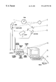
- the present apparatus is provided in a prior art manner with a laser scanning ophthalmoscope having a scanning device, which preferably is composed of an x,y-scanner with a polygon mirror drum ( 1 ) and a galvanometer mirror ( 2 ) as such a system operates independently of wavelengths, which is an advantage when light of several wavelengths is employed simultaneously.
- a laser scanning ophthalmoscope having a scanning device, which preferably is composed of an x,y-scanner with a polygon mirror drum ( 1 ) and a galvanometer mirror ( 2 ) as such a system operates independently of wavelengths, which is an advantage when light of several wavelengths is employed simultaneously.
- the scanning device directs the beam of a laser ( 3 ) to an eye ( 4 ), which is to be examined and treated, in such a manner that the laser beam scans the area to be treated.
- the light reflected by the eye is directed via the scanning device to a detector device ( 5 ), whose time sequential output signals are fed synchronically to the scanning movement by an electronic control and evaluation unit of prior art construction, to a video monitor on which in this manner a visual representation of the eye becomes visible.
- the control unit ( 10 ) not only regulates the power and the firing time of laser ( 7 ), but also the laser beam's point of impact in the eye via a beam manipulator ( 8 ) in such a manner that the laser beam concurs with a marking provided in the projected visual representation.
- control unit ( 10 ) adjusts the projected visual representation, which the operator has made to concur with that of the eye, when the eye to be examined moves. Moreover, said control unit permits the manipulation of a visual representation which was previously recorded by the invented apparatus or by another examining device prior to the actual treatment. In this manner, by way of illustration, the head ophthalomogist can plan the treatment—coagulation or cutting location, the laser power output etc.—but leave the actual treatment to an assistant.
- the control unit can also take over the regulation of other units, e.g. it can regulate the laser power output in accordance with the algorithms described in DE-OS 30 24 169 or DE-OS 33 06 981.
- the beam of the coagulation laser thus by way of illustration of an AR + -laser or a color laser, is projected between the scanning device and the eye.
- the joint use of the “scanning device” permits, particularly in this case, treating a larger area or several areas in one step.
- An apparatus for the observation of the rear portion of the eye with a scanning illumination is particularly predestined as an image generator for a so-called eye tracking unit due to its reflex-free and high-analyzing image representation.
Abstract
Description
Claims (7)
Priority Applications (1)
| Application Number | Priority Date | Filing Date | Title |
|---|---|---|---|
| US08/208,901 US6267756B1 (en) | 1986-03-08 | 1994-03-11 | Apparatus for the observation and the treatment of the eye using a laser |
Applications Claiming Priority (10)
| Application Number | Priority Date | Filing Date | Title |
|---|---|---|---|
| DE3607721 | 1986-03-08 | ||
| DE19863607721 DE3607721A1 (en) | 1986-03-08 | 1986-03-08 | DEVICE FOR LASER TREATMENT OF THE EYE |
| DE19863638226 DE3638226A1 (en) | 1986-11-08 | 1986-11-08 | DEVICE FOR OBSERVING THE REAR EYE SECTIONS |
| DE3638226 | 1986-11-08 | ||
| US31843889A | 1989-03-02 | 1989-03-02 | |
| US44593389A | 1989-12-05 | 1989-12-05 | |
| US56976990A | 1990-08-22 | 1990-08-22 | |
| US71138791A | 1991-06-06 | 1991-06-06 | |
| US464993A | 1993-01-14 | 1993-01-14 | |
| US08/208,901 US6267756B1 (en) | 1986-03-08 | 1994-03-11 | Apparatus for the observation and the treatment of the eye using a laser |
Related Parent Applications (1)
| Application Number | Title | Priority Date | Filing Date |
|---|---|---|---|
| US464993A Continuation | 1986-03-08 | 1993-01-14 |
Publications (1)
| Publication Number | Publication Date |
|---|---|
| US6267756B1 true US6267756B1 (en) | 2001-07-31 |
Family
ID=27561447
Family Applications (1)
| Application Number | Title | Priority Date | Filing Date |
|---|---|---|---|
| US08/208,901 Expired - Fee Related US6267756B1 (en) | 1986-03-08 | 1994-03-11 | Apparatus for the observation and the treatment of the eye using a laser |
Country Status (1)
| Country | Link |
|---|---|
| US (1) | US6267756B1 (en) |
Cited By (24)
| Publication number | Priority date | Publication date | Assignee | Title |
|---|---|---|---|---|
| US20030231827A1 (en) * | 2002-04-08 | 2003-12-18 | Andersen Dan E. | System, method and apparatus for providing uniform illumination |
| US20050185138A1 (en) * | 2004-02-19 | 2005-08-25 | Visx, Incorporated | Methods and systems for differentiating left and right eye images |
| US20050288745A1 (en) * | 2004-06-28 | 2005-12-29 | Andersen Dan E | Method and device for optical ophthalmic therapy |
| US20050286019A1 (en) * | 2004-06-10 | 2005-12-29 | Wiltberger Michael W | Scanning ophthalmic fixation method and apparatus |
| US20060044510A1 (en) * | 1996-12-23 | 2006-03-02 | University Of Rochester | Method and apparatus for improving vision and the resolution of retinal images |
| US20060100677A1 (en) * | 2003-12-24 | 2006-05-11 | Blumenkranz Mark S | Patterned laser treatment of the retina |
| US7044602B2 (en) | 2002-05-30 | 2006-05-16 | Visx, Incorporated | Methods and systems for tracking a torsional orientation and position of an eye |
| US20070121069A1 (en) * | 2005-11-16 | 2007-05-31 | Andersen Dan E | Multiple spot photomedical treatment using a laser indirect ophthalmoscope |
| US20070129709A1 (en) * | 2005-12-01 | 2007-06-07 | Andersen Dan E | System and method for minimally traumatic ophthalmic photomedicine |
| US20080033406A1 (en) * | 2006-04-28 | 2008-02-07 | Dan Andersen | Dynamic optical surgical system utilizing a fixed relationship between target tissue visualization and beam delivery |
| US7438713B2 (en) | 2001-03-22 | 2008-10-21 | Lumenis, Inc. | Scanning laser handpiece with shaped output beam |
| US20080319427A1 (en) * | 2007-03-13 | 2008-12-25 | Palanker Daniel V | Computer guided patterned laser trabeculoplasty |
| WO2011116900A1 (en) * | 2010-03-20 | 2011-09-29 | Carl Zeiss Meditec Ag | Ophthalmological laser treatment device |
| EP2386244A3 (en) * | 2006-07-07 | 2012-09-12 | OD-OS GmbH | Ophthalmoscope |
| US8764188B2 (en) | 2011-10-21 | 2014-07-01 | Kent Tabor | Functional vision tester |
| WO2016024841A1 (en) * | 2014-08-13 | 2016-02-18 | (주)루트로닉 | Ophthalmic treatment device and control method therefor |
| US9265458B2 (en) | 2012-12-04 | 2016-02-23 | Sync-Think, Inc. | Application of smooth pursuit cognitive testing paradigms to clinical drug development |
| US9380976B2 (en) | 2013-03-11 | 2016-07-05 | Sync-Think, Inc. | Optical neuroinformatics |
| US10179071B2 (en) | 2005-09-19 | 2019-01-15 | Topcon Medical Laser Systems, Inc. | System and method for generating treatment patterns |
| US10524656B2 (en) | 2005-10-28 | 2020-01-07 | Topcon Medical Laser Systems Inc. | Photomedical treatment system and method with a virtual aiming device |
| US10617564B1 (en) | 2006-05-10 | 2020-04-14 | Apple Inc. | Area scanning photomedicine device and method |
| US11382794B2 (en) | 2018-07-02 | 2022-07-12 | Belkin Laser Ltd. | Direct selective laser trabeculoplasty |
| US11564836B2 (en) | 2010-05-10 | 2023-01-31 | Ramot At Tel Aviv University Ltd. | System and method for treating an eye |
| US11771596B2 (en) | 2010-05-10 | 2023-10-03 | Ramot At Tel-Aviv University Ltd. | System and method for treating an eye |
Citations (11)
| Publication number | Priority date | Publication date | Assignee | Title |
|---|---|---|---|---|
| US4213678A (en) * | 1977-09-29 | 1980-07-22 | Retina Foundation | Scanning ophthalmoscope for examining the fundus of the eye |
| US4266549A (en) * | 1978-10-12 | 1981-05-12 | Hiroaki Kimura | Laser scalpel |
| DE3024169A1 (en) * | 1980-06-27 | 1982-01-28 | Reginald Dipl.-Phys. Dr. 8021 Taufkirchen Birngruber | DEVICE FOR PHOTOCOAGULATING BIOLOGICAL TISSUE |
| DE3148748A1 (en) * | 1981-12-09 | 1983-07-21 | Karp, Manfred, 5300 Bonn | Device for influencing highly sensitive surfaces |
| DE3425975A1 (en) * | 1984-07-14 | 1986-01-16 | Benedikt Dr.med. 8995 Sigmarszell Jean | SLIT LAMP FOR VIEWING THE EYE BACKGROUND |
| US4579430A (en) * | 1982-12-11 | 1986-04-01 | Carl-Zeiss-Stiftung | Method and apparatus for forming an image of the ocular fundus |
| US4654701A (en) * | 1984-09-03 | 1987-03-31 | Olympus Optical Co., Ltd. | Biopsy information recording apparatus for endoscope |
| US4669466A (en) * | 1985-01-16 | 1987-06-02 | Lri L.P. | Method and apparatus for analysis and correction of abnormal refractive errors of the eye |
| US4672963A (en) * | 1985-06-07 | 1987-06-16 | Israel Barken | Apparatus and method for computer controlled laser surgery |
| WO1987005205A1 (en) * | 1986-03-08 | 1987-09-11 | G. Rodenstock Instrumente Gmbh | Laser installation for examining and treating the eye |
| US4719912A (en) * | 1983-02-28 | 1988-01-19 | Promed Technology, Inc. | Apparatus for controlling the photocoagulation of biological tissue |
-
1994
- 1994-03-11 US US08/208,901 patent/US6267756B1/en not_active Expired - Fee Related
Patent Citations (12)
| Publication number | Priority date | Publication date | Assignee | Title |
|---|---|---|---|---|
| US4213678A (en) * | 1977-09-29 | 1980-07-22 | Retina Foundation | Scanning ophthalmoscope for examining the fundus of the eye |
| US4266549A (en) * | 1978-10-12 | 1981-05-12 | Hiroaki Kimura | Laser scalpel |
| DE3024169A1 (en) * | 1980-06-27 | 1982-01-28 | Reginald Dipl.-Phys. Dr. 8021 Taufkirchen Birngruber | DEVICE FOR PHOTOCOAGULATING BIOLOGICAL TISSUE |
| DE3148748A1 (en) * | 1981-12-09 | 1983-07-21 | Karp, Manfred, 5300 Bonn | Device for influencing highly sensitive surfaces |
| US4579430A (en) * | 1982-12-11 | 1986-04-01 | Carl-Zeiss-Stiftung | Method and apparatus for forming an image of the ocular fundus |
| US4719912A (en) * | 1983-02-28 | 1988-01-19 | Promed Technology, Inc. | Apparatus for controlling the photocoagulation of biological tissue |
| DE3425975A1 (en) * | 1984-07-14 | 1986-01-16 | Benedikt Dr.med. 8995 Sigmarszell Jean | SLIT LAMP FOR VIEWING THE EYE BACKGROUND |
| US4654701A (en) * | 1984-09-03 | 1987-03-31 | Olympus Optical Co., Ltd. | Biopsy information recording apparatus for endoscope |
| US4669466A (en) * | 1985-01-16 | 1987-06-02 | Lri L.P. | Method and apparatus for analysis and correction of abnormal refractive errors of the eye |
| US4721379A (en) * | 1985-01-16 | 1988-01-26 | Lri L.P. | Apparatus for analysis and correction of abnormal refractive errors of the eye |
| US4672963A (en) * | 1985-06-07 | 1987-06-16 | Israel Barken | Apparatus and method for computer controlled laser surgery |
| WO1987005205A1 (en) * | 1986-03-08 | 1987-09-11 | G. Rodenstock Instrumente Gmbh | Laser installation for examining and treating the eye |
Non-Patent Citations (1)
| Title |
|---|
| Awo Abstracts vol. 38, Summary 92. * |
Cited By (50)
| Publication number | Priority date | Publication date | Assignee | Title |
|---|---|---|---|---|
| US20060044510A1 (en) * | 1996-12-23 | 2006-03-02 | University Of Rochester | Method and apparatus for improving vision and the resolution of retinal images |
| US7416305B2 (en) | 1996-12-23 | 2008-08-26 | University Of Rochester | Method and apparatus for improving vision and the resolution of retinal images |
| US7824396B2 (en) | 2001-03-22 | 2010-11-02 | Lumenis Ltd. | Scanner laser handpiece with shaped output beam |
| US7438713B2 (en) | 2001-03-22 | 2008-10-21 | Lumenis, Inc. | Scanning laser handpiece with shaped output beam |
| US7263255B2 (en) | 2002-04-08 | 2007-08-28 | Lumenis Inc. | System, method and apparatus for providing uniform illumination |
| US20030231827A1 (en) * | 2002-04-08 | 2003-12-18 | Andersen Dan E. | System, method and apparatus for providing uniform illumination |
| US7431457B2 (en) | 2002-05-30 | 2008-10-07 | Amo Manufacturing Usa, Llc | Methods and systems for tracking a torsional orientation and position of an eye |
| US9596983B2 (en) | 2002-05-30 | 2017-03-21 | Amo Manufacturing Usa, Llc | Methods and systems for tracking a torsional orientation and position of an eye |
| US10251783B2 (en) | 2002-05-30 | 2019-04-09 | Amo Manufacturing Usa, Llc | Methods and systems for tracking a torsional orientation and position of an eye |
| US8740385B2 (en) | 2002-05-30 | 2014-06-03 | Amo Manufacturing Usa, Llc | Methods and systems for tracking a torsional orientation and position of an eye |
| US7261415B2 (en) | 2002-05-30 | 2007-08-28 | Visx, Incorporated | Methods and systems for tracking a torsional orientation and position of an eye |
| US7044602B2 (en) | 2002-05-30 | 2006-05-16 | Visx, Incorporated | Methods and systems for tracking a torsional orientation and position of an eye |
| US20060161141A1 (en) * | 2002-05-30 | 2006-07-20 | Visx, Incorporated | Methods and Systems for Tracking a Torsional Orientation and Position of an Eye |
| US20060100677A1 (en) * | 2003-12-24 | 2006-05-11 | Blumenkranz Mark S | Patterned laser treatment of the retina |
| US7766903B2 (en) | 2003-12-24 | 2010-08-03 | The Board Of Trustees Of The Leland Stanford Junior University | Patterned laser treatment of the retina |
| US8007106B2 (en) | 2004-02-19 | 2011-08-30 | Amo Manufacturing Usa, Llc | Systems for differentiating left and right eye images |
| US20050185138A1 (en) * | 2004-02-19 | 2005-08-25 | Visx, Incorporated | Methods and systems for differentiating left and right eye images |
| US7481536B2 (en) | 2004-02-19 | 2009-01-27 | Amo Manufacturing Usa, Llc | Methods and systems for differentiating left and right eye images |
| US20090099558A1 (en) * | 2004-02-19 | 2009-04-16 | Amo Manufacturing Usa, Llc | Methods and Systems for Differentiating Left and Right Eye Images |
| US20050286019A1 (en) * | 2004-06-10 | 2005-12-29 | Wiltberger Michael W | Scanning ophthalmic fixation method and apparatus |
| US7452081B2 (en) | 2004-06-10 | 2008-11-18 | Optimedica Corporation | Scanning ophthalmic fixation method and apparatus |
| US7452080B2 (en) | 2004-06-10 | 2008-11-18 | Optimedica Corporation | Scanning ophthalmic fixation method and apparatus |
| US11026860B2 (en) | 2004-06-28 | 2021-06-08 | Iridex | Method and device for optical ophthalmic therapy |
| US20050288745A1 (en) * | 2004-06-28 | 2005-12-29 | Andersen Dan E | Method and device for optical ophthalmic therapy |
| US10744036B2 (en) | 2005-09-19 | 2020-08-18 | Topcon Medical Laser Systems, Inc. | System and method for generating treatment patterns |
| US10179071B2 (en) | 2005-09-19 | 2019-01-15 | Topcon Medical Laser Systems, Inc. | System and method for generating treatment patterns |
| US10524656B2 (en) | 2005-10-28 | 2020-01-07 | Topcon Medical Laser Systems Inc. | Photomedical treatment system and method with a virtual aiming device |
| US11406263B2 (en) | 2005-10-28 | 2022-08-09 | Iridex Corporation | Photomedical treatment system and method with a virtual aiming device |
| US10912678B2 (en) | 2005-11-16 | 2021-02-09 | Topcon Medical Laser Systems Inc. | Multiple spot photomedical treatment using a laser indirect ophthalmoscope |
| US20070121069A1 (en) * | 2005-11-16 | 2007-05-31 | Andersen Dan E | Multiple spot photomedical treatment using a laser indirect ophthalmoscope |
| US9681985B2 (en) | 2005-12-01 | 2017-06-20 | Topcon Medical Laser Systems, Inc. | System and method for minimally traumatic ophthalmic photomedicine |
| US20070129709A1 (en) * | 2005-12-01 | 2007-06-07 | Andersen Dan E | System and method for minimally traumatic ophthalmic photomedicine |
| US20080033406A1 (en) * | 2006-04-28 | 2008-02-07 | Dan Andersen | Dynamic optical surgical system utilizing a fixed relationship between target tissue visualization and beam delivery |
| US8771261B2 (en) | 2006-04-28 | 2014-07-08 | Topcon Medical Laser Systems, Inc. | Dynamic optical surgical system utilizing a fixed relationship between target tissue visualization and beam delivery |
| US10617564B1 (en) | 2006-05-10 | 2020-04-14 | Apple Inc. | Area scanning photomedicine device and method |
| EP2386243A3 (en) * | 2006-07-07 | 2012-09-12 | OD-OS GmbH | Ophthalmoscope |
| EP2386244A3 (en) * | 2006-07-07 | 2012-09-12 | OD-OS GmbH | Ophthalmoscope |
| US20080319427A1 (en) * | 2007-03-13 | 2008-12-25 | Palanker Daniel V | Computer guided patterned laser trabeculoplasty |
| US8568393B2 (en) | 2007-03-13 | 2013-10-29 | Topcon Medical Laser Systems, Inc. | Computer guided patterned laser trabeculoplasty |
| WO2011116900A1 (en) * | 2010-03-20 | 2011-09-29 | Carl Zeiss Meditec Ag | Ophthalmological laser treatment device |
| US8858540B2 (en) | 2010-03-20 | 2014-10-14 | Carl Zeiss Meditec Ag | Ophthalmological laser treatment device |
| US11564836B2 (en) | 2010-05-10 | 2023-01-31 | Ramot At Tel Aviv University Ltd. | System and method for treating an eye |
| US11771596B2 (en) | 2010-05-10 | 2023-10-03 | Ramot At Tel-Aviv University Ltd. | System and method for treating an eye |
| US8764188B2 (en) | 2011-10-21 | 2014-07-01 | Kent Tabor | Functional vision tester |
| US9149185B2 (en) | 2011-10-21 | 2015-10-06 | Vision Assessment Corporation | Functional vision tester |
| US9265458B2 (en) | 2012-12-04 | 2016-02-23 | Sync-Think, Inc. | Application of smooth pursuit cognitive testing paradigms to clinical drug development |
| US9380976B2 (en) | 2013-03-11 | 2016-07-05 | Sync-Think, Inc. | Optical neuroinformatics |
| US10575987B2 (en) | 2014-08-13 | 2020-03-03 | Lutronic Corporation | Ophthalmic treatment device and control method therefor |
| WO2016024841A1 (en) * | 2014-08-13 | 2016-02-18 | (주)루트로닉 | Ophthalmic treatment device and control method therefor |
| US11382794B2 (en) | 2018-07-02 | 2022-07-12 | Belkin Laser Ltd. | Direct selective laser trabeculoplasty |
Similar Documents
| Publication | Publication Date | Title |
|---|---|---|
| US6267756B1 (en) | Apparatus for the observation and the treatment of the eye using a laser | |
| EP1223847B1 (en) | Two camera off-axis eye tracker | |
| US6491687B1 (en) | Corneal Surgery apparatus | |
| AU767927B2 (en) | Eye tracking and positioning system for a refractive laser system | |
| US6257722B1 (en) | Ophthalmic apparatus | |
| JP5028073B2 (en) | Cornea surgery device | |
| JP3655022B2 (en) | Ophthalmic surgery equipment | |
| JP2000139996A (en) | Cornea operating device | |
| JPH01500009A (en) | Split light device for eye treatment using laser | |
| JPH10192334A (en) | Ophthalmic operation device | |
| EP1369078B1 (en) | Ophthalmic apparatus | |
| JP2593085B2 (en) | Eye examination and treatment equipment using lasers | |
| US20060142742A1 (en) | Device for ophthalmologically treating the eye using a fixation light beam | |
| AU718942B2 (en) | Medical laser guidance apparatus | |
| JPH10192333A (en) | Ophthalmic operation device | |
| Roduit et al. | Eye-guided surgical microscope |
Legal Events
| Date | Code | Title | Description |
|---|---|---|---|
| FPAY | Fee payment |
Year of fee payment: 4 |
|
| AS | Assignment |
Owner name: G. RODENSTOCK INSTRUMENTE GMBH, GERMANY Free format text: ASSIGNMENT OF ASSIGNORS INTEREST;ASSIGNORS:FEUERSTEIN, MANFRED;KLINGBEIL, ULRICH;LANGOSCH, HERBERT;AND OTHERS;REEL/FRAME:017366/0645;SIGNING DATES FROM 19870830 TO 19870930 Owner name: DR. WINFRIED ANDRES (RECEIVER FOR PRO-LASER-WECO-G Free format text: ASSIGNMENT OF ASSIGNORS INTEREST;ASSIGNOR:PRO-LASER WECO GMBH;REEL/FRAME:017366/0214 Effective date: 20020425 Owner name: PRO-LASER WECO GMBH, GERMANY Free format text: MERGER AND CHANGE OF NAME;ASSIGNOR:G. RODENSTOCK INSTRUMENTE GMBH;REEL/FRAME:017366/0581 Effective date: 20010223 Owner name: BUCHMANN DEUTSCHLAND GMBH, GERMANY Free format text: ASSIGNMENT OF ASSIGNORS INTEREST;ASSIGNOR:ANDRES, WINFRIED (RECEIVER FOR PRO-LASER WECO GMBH);REEL/FRAME:017366/0227 Effective date: 20021220 Owner name: HEIDELBERG ENGINEERING GMBH, GERMANY Free format text: ASSIGNMENT OF ASSIGNORS INTEREST;ASSIGNOR:BUCHMANN DEUTSCHLAND GMBH;REEL/FRAME:017366/0222 Effective date: 20050824 |
|
| FPAY | Fee payment |
Year of fee payment: 8 |
|
| REMI | Maintenance fee reminder mailed | ||
| LAPS | Lapse for failure to pay maintenance fees | ||
| STCH | Information on status: patent discontinuation |
Free format text: PATENT EXPIRED DUE TO NONPAYMENT OF MAINTENANCE FEES UNDER 37 CFR 1.362 |
|
| FP | Lapsed due to failure to pay maintenance fee |
Effective date: 20130731 |