US6275239B1 - Media coprocessor with graphics video and audio tasks partitioned by time division multiplexing - Google Patents
Media coprocessor with graphics video and audio tasks partitioned by time division multiplexing Download PDFInfo
- Publication number
- US6275239B1 US6275239B1 US09/137,017 US13701798A US6275239B1 US 6275239 B1 US6275239 B1 US 6275239B1 US 13701798 A US13701798 A US 13701798A US 6275239 B1 US6275239 B1 US 6275239B1
- Authority
- US
- United States
- Prior art keywords
- video
- data
- graphics
- audio
- partition
- Prior art date
- Legal status (The legal status is an assumption and is not a legal conclusion. Google has not performed a legal analysis and makes no representation as to the accuracy of the status listed.)
- Expired - Lifetime
Links
Images


Classifications
-
- H—ELECTRICITY
- H04—ELECTRIC COMMUNICATION TECHNIQUE
- H04N—PICTORIAL COMMUNICATION, e.g. TELEVISION
- H04N19/00—Methods or arrangements for coding, decoding, compressing or decompressing digital video signals
- H04N19/42—Methods or arrangements for coding, decoding, compressing or decompressing digital video signals characterised by implementation details or hardware specially adapted for video compression or decompression, e.g. dedicated software implementation
-
- G—PHYSICS
- G06—COMPUTING; CALCULATING OR COUNTING
- G06T—IMAGE DATA PROCESSING OR GENERATION, IN GENERAL
- G06T1/00—General purpose image data processing
- G06T1/20—Processor architectures; Processor configuration, e.g. pipelining
-
- H—ELECTRICITY
- H04—ELECTRIC COMMUNICATION TECHNIQUE
- H04N—PICTORIAL COMMUNICATION, e.g. TELEVISION
- H04N19/00—Methods or arrangements for coding, decoding, compressing or decompressing digital video signals
- H04N19/60—Methods or arrangements for coding, decoding, compressing or decompressing digital video signals using transform coding
- H04N19/61—Methods or arrangements for coding, decoding, compressing or decompressing digital video signals using transform coding in combination with predictive coding
Definitions
- the present invention relates to an integrated media coprocessor chip which partitions graphics, video, and audio tasks through time division multiplexing.
- Computing devices take many different shapes, sizes, and costs. These computing devices range from portable hand-held organizers, computers, set-top units, gaming consoles to electronic “appliances.” At the heart of each computer device lies a microprocessor which acts as the brain of the device. Successive generations of microprocessor designs have resulted in faster speeds and enhanced processing power. However, the overall price charged for any given computing device has historically tended to remain the same. In general, one would expect to pay roughly the same amount of money for the purchase of a new PC or gaming console today as a few years ago, except that today's devices would be much faster and have improved performance and functionalities (e.g., superior three-dimensional graphics and/or video capabilities which runs at faster speeds).
- the present invention provides a much less expensive computing system without sacrificing much in the way of functionality, quality, and versatility.
- the present invention achieves this by designing a single, integrated media co-processor chip which is capable of processing graphics, video and audio. This reduces costs because it minimizes duplicate functionalities and redundant circuitry.
- the present invention partitions different media tasks so that they are performed sequentially in a time-division multiplexed format. For a given amount of time synchronized to the video frame, a specified amount of time is partitioned to perform audio tasks; a specified amount of time is partitioned to process video; and the time left over is partitioned to render graphics.
- the present invention relates to an integrated media coprocessor chip which partitions 3-D graphics, video, and audio tasks through time division multiplexing.
- the media coprocessor is comprised of a single IC semiconductor chip which is coupled with a host processor chip, one or more memory chips, and an I/O controller chip.
- the media coprocessor is comprised of a digital bitstream processor, a digital signal processor, and a display processor.
- An update interval, synchronized to a video frame, is defined. This update interval is divided into a number of partitions. Audio data is processed during one of the partitions. Video data is processed during another partition. And 3-D graphics is processed in yet a third partition.
- partitions are then processed sequentially in a time-division multiplex scheme by the media coprocessor chip. Because the media coprocessor chip performs each of these tasks in a partitioned, time-division multiplexed scheme, certain circuits can be used to perform the same functions with respect to audio, video, and/or 3-D graphics applications. Thereby, expenses are minimized with minimal impact to performance.
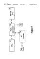
- FIG. 1 shows a block diagram of a processing system using an integrated media coprocessor and a unified memory according to the present invention.
- FIG. 2 is a block diagram of the media coprocessor.
- FIG. 3 shows an embodiment of the present invention used as a display system.
- FIG. 4 illustrates the circuitry of the media coprocessor of the present invention.
- FIG. 5 shows a timing diagram of the partitioning.
- FIG. 6 illustrates an exemplary time-division multiplexing scheme.
- FIG. 7 shows a data structure for performing the partitioning scheme of the present invention.
- FIG. 8 shows a block diagram for the currently preferred embodiment for applications partitioning.
- FIG. 9 shows an applications data flow diagram.
- a media coprocessor chip which partitions 3-D graphics, video, and audio tasks through time division multiplexing is described.
- numerous specific details are set forth in order to provide a thorough understanding of the present invention. It will be obvious, however, to one skilled in the art that the present invention may be practiced without these specific details. In other instances, well-known structures and devices are shown in block diagram form in order to avoid obscuring the present invention.
- FIG. 1 shows a block diagram of a processing system using an integrated media coprocessor and a unified memory upon which the present invention may be practiced.
- the media coprocessor is comprised of a single IC semiconductor chip which is coupled with a host processor chip, one or more memory chips, and an I/O controller chip. More particularly, a standard central processing unit (CPU) 101 is coupled to media coprocessor 102 .
- CPU 101 is a commercially available microprocessor (e.g., Intel or MIPS) which provides a portable high-performance applications platform with a complete high-level language development environment.
- the media coprocessor 102 is a low cost application specific integrated circuit (ASIC) chip which supports real-time 3-D graphics, video, and audio.
- ASIC application specific integrated circuit
- the media coprocessor 102 provides an application performance spectrum including: 3D textured, shaded, z-buffered, antialiased, blended polygons; 2D scaled, rotated, and translated transparent sprite image; full-screen frame-rate MPEG2 (i.e., ISO/IEC 13818-x) video and audio decompression; full-screen frame-rate video display including scaling, filtering, keying, and compositing; and audio wavetable synthesis and signal processing.
- Media coprocessor 102 outputs video and audio signals for display of 3-D graphics/video and playback of sound/speech.
- the video output supports NTSC and PAL resolutions with a full-color display, while the audio output supports stereo sound.
- a memory array 103 is coupled to media coprocessor 102 for temporary storage of data and instructions.
- Memory array 103 is comprised of commercially available dynamic random access memories (DRAMs). All applications code and data, as well as display and I/O buffers, share the memory array 103 , thereby allowing the greatest applications flexibility at the lowest memory cost.
- An input/output (I/O) controller 104 is also coupled to media coprocessor 102 .
- I/O controller 104 is an intelligent direct memory access (DMA) engine which transfers data between memory buffers and I/O interfaces, including video and audio input and a variety of peripheral interfaces for control and data (e.g., network interfaces and mass storage devices).
- DMA direct memory access
- the memory 103 is a single array of DRAMs used for all the product memory requirements, such as system and application memory, display buffer, intermediary motion picture experts group (MPEG) frames, and I/O buffering. Video display from this array with all the other usages require a very high speed interface, such as a synchronous or Rambus DRAMs.
- the Z buffer and a second frame buffer fro 3-D graphics would not be in use concurrently with the three MPEG frames.
- a PAL display format would increase the size of each frame by approximately 15%.
- FIG. 2 is a block diagram of the media coprocessor 102 .
- the media coprocessor 102 is comprised of several functional units: the digital bitstream processor 201 , digital signal processor 202 , display processor 203 , audio/video I/O port 204 , and memory controller 205 .
- Memory controller 205 optimizes DRAM block transfers for the CPU 101 , audio, video and I/O ports 204 , and the three processor units 201 - 203 .
- the digital bitstream processor 201 performs decoding of variable length code (VLC) digital bitstream data.
- the digital signal processor 202 is a microcoded single instruction multiple data (SIMD) processor with parallel integer multiplier-accumulators.
- SIMD microcoded single instruction multiple data
- the digital signal processor 202 performs video and audio decompression and filtering and geometry processing in conjunction with the CPU 101 for 2D and 3D graphics.
- the display processor 203 is a data-driven display pipeline supporting both geometric 3-D graphics and image data types. For 3D graphics, the display processor 203 renders fully textured, shaded, antialiased, z-buffered, alpha-blended polygons. For video and 2D graphics, the display processor 203 scales, rotates, translates, filters, and composites images or sprites with per-pixel transparency. For video decompression, the display processor 203 performs motion compensation and reconstruction.
- the media coprocessor 102 offers dramatic levels of cost/performance to applications. Furthermore, in order to maximize quality and performance with minimal memory, the media coprocessor 102 full color image type is 4:2:0 YUV (e.g., luma and subsampled chroma with 8 bits per component), for all 3-D graphics rendering as well as video and display. Thereby, this eliminates the need for any color conversions.
- YUV e.g., luma and subsampled chroma with 8 bits per component
- Patent Aapplication Serial Number entitled “A Method And System For Performing Rasterization In Producing Three Dimensional Graphics Using YUV Color Space And Combining Same With Digital Video In YUV Color Space”, filed concurrently herewith, and assigned to the assignee of the present invention and which is hereby incorporated by reference in its entirety.
- Various texture image types with fewer bits per pixel than full color are also supported.
- traditional 3-D graphics uses 8 bit red, green, and blue channels per pixel
- YUV offers compelling advantages when the display device is a consumer television instead of a computer monitor.
- One embodiment of the present invention includes a media coprocessor circuit 102 for generating signals 350 that are used to drive a display screen 310 .
- Signals on line 350 are a digital pixel stream with video timing to an external video encoder (RF modulator circuit) 320 .
- the display screen 310 is a television set, however, it is appreciated that the present invention is equally well suited to provide signals for driving displays of other cathode ray tube (CRT) technologies, computer monitors, or flat panel display screens (field emission, liquid crystal display, etc.).
- the television set provides up to 720 ⁇ 480 resolution for high quality NTSC (720 ⁇ 576 for PAL).
- the display buffer described below, is doubled buffered so that various video and 3-D graphics functions can create a composite image without visible artifacts.
- the media coprocessor circuit 102 of the present invention advantageously includes a digital video producing subsystem 330 b integrated with a three dimensional 3-D graphics subsystem 330 a , both systems processing image data in YUV color coordinates (e.g., according to the CCIR- 601 color standard). These circuits are described in more detail in FIG. 4 below.
- the digital video producing subsystem 230 b processes image data using YUV color coordinates.
- the digital video subsystem 230 b produces digital video signals in accordance with the Motion Pictures Expert Group (MPEG II) information transmission standard.
- MPEG II Motion Pictures Expert Group
- the digital video subsystem 230 b and the three dimensional graphics subsystem 230 a of FIG. 3 are both coupled to a common (e.g., single) memory unit 103 for storage and retrieval of image information encoded in YUV color coordinates thereby obviating the need for a duplicate memory system as required of the prior art.
- the digital video subsystem 330 b and the three dimensional graphics subsystem 330 a are implemented on a single integrated circuit chip.
- the common memory unit 103 can also be integrated into the above circuit chip in one embodiment.
- the three dimensional graphics system 330 a advantageously generates digital image information using YUV color encoded coordinates (e.g., using Y, Cr, Cb coordinates). That is, all color representations, manipulations, stores, transfers, etc., with respect to image information (e.g., graphic primitive rasterization, texture mapping, filtering, anti-aliasing, deflicker filtering, etc.) exist and are performed by the three dimensional graphics subsystem 330 a using Y, Cr and Cb color coordinate values. Therefore, the three dimensional graphics subsystem 330 a stores and accesses image information from the common memory unit 103 using Y, Cr and Cb color coordinates.
- image information e.g., graphic primitive rasterization, texture mapping, filtering, anti-aliasing, deflicker filtering, etc.
- RGB color coordinates are not used by the three dimensional graphics subsystem 330 a in accordance with the present invention.
- the YUV and YCrCb color encoding formats are used interchangeably and among these two color formats, one format could be replaced with the other without departing from the spirit and scope of the present invention.
- the digital video producing subsystem 330 b in accordance with the present invention, produces digital video information using YUV color coordinates.
- the digital video subsystem 330 b can be implemented using any of a number of well known digital video producing components, such as a bit stream from a digital CDROM, a video camera, a video tuner, any of a number of compact disk players, a digital video disk (DVD), a video hard drive, or any of a number of MPEG II compatible bit stream producers.
- Video sources range in resolution from 320 ⁇ 240 up to 720 ⁇ 480 and can be displayed from full screen to icon-sized or zoomed.
- the digital video subsystem 330 b produces digital video using the YUV color encoded format. That is, color information is represented, manipulated, stored and supplied in Y, Cr, Cb color coordinates within the digital video subsystem 330 b . Therefore, the digital video subsystem 330 b also stores and accesses image information from the common memory unit 103 using Y, Cr and Cb color coordinates.
- a video decompression e.g., MPEG
- Scaling e.g., resize, zoom
- filtering e.g., noise reduction
- Keying e.g., alpha from chroma or luma
- a copy step e.g., pan, scroll, wipe
- a blending step e.g., fade, dissolve, matte
- the display system 300 of FIG. 3 includes a common memory unit 103 (“frame buffer”) which is coupled to media coprocessor circuit 102 and in one embodiment can also be integrated within media coprocessor circuit 102 .
- common memory unit 103 is implemented with a single array of commercially available DRAMs and provides at least 250 Mbytes per second peak bandwidth in configurations of 4 Mbytes on up.
- Common memory unit 103 is used for system memory, application memory, display buffer memory, intermediary MPEG frames and input/output buffering.
- Common memory unit 103 receives image information in Y, Cr, Cb encoded color coordinates from the digital video subsystem 330 b and also from the three dimensional graphics subsystem 330 a .
- Common memory unit 103 also supplies image information in Y, Cr, Cb encoded color coordinates to the digital video subsystem 330 b and also to the three dimensional graphics subsystem 330 a.
- the present invention advantageously avoids the need to provide duplicate memory units for subsystem 330 a and for subsystem 330 b , as required of the prior art display systems. This is accomplished by the present invention, in part, by providing a three dimensional graphics subsystem 330 b that performs all color representations and manipulations in Y, Cr, Cb color coordinates.
- YUV color encoded image information is stored into and accessed from the common memory unit 103 over bidirectional bus 345 .
- media coprocessor circuit 102 is capable of providing color coded digital image information over bus 350 to a converter/driver circuit 320 .
- the converter/driver circuit 320 transforms the digital image information to an analog signal 312 that is used to drive the display screen 310 .
- a number of well known technologies can be used to implement circuit 320 .
- the NTSC signal 312 is used to drive a television monitor 310 .
- media coprocessor circuit 102 can be added to media coprocessor circuit 102 to allow the mixing of YUV color encoded image data from the digital video signal subsystem 330 b and from the three dimensional graphic subsystem 330 a .
- the three dimensional graphics subsystem 330 b includes circuitry for combining digital video information with 3-D graphics data.
- Applications running on media coprocessor circuit 102 can combine several different image sources into a single display.
- An exemplary display might consist of 3-D graphics generated icons above decompressed video actors moving around a synthetic 3-D graphics environment with a digitized video background.
- media coprocessor circuit 102 provides sufficient composite resources such that a single display buffer image can be assembled from the various image sources under software control. In this embodiment, the entire composite image may need to be redrawn for each screen update, but less memory, display bandwidth, and hardware is needed using this approach.
- Display system 300 can also include a host processor 101 coupled to the media coprocessor 102 .
- a host processor 101 coupled to the media coprocessor 102 .
- a commercially available MIPS4 64 bit processor is used as the host processor 101 .
- the host processor 101 provides a portable high performance applications platform with a complete high level language development environment.
- FIG. 4 illustrates the circuitry of the media coprocessor 102 of the present invention in more detail.
- the media coprocessor 102 includes a digital signal processor 202 , a bit stream processor 201 and a display processor 203 .
- Media coprocessor 102 of FIG. 4 includes a host bus interface 401 (e.g., a Peripheral Component Interface) for communicating with a host bus 402 of the host processor.
- Data 403 and control 404 busses are connected to the host bus interface 401 .
- Media coprocessor 102 also contains an instruction memory 405 coupled to the 32-bit data bus 403 and an instruction processor 406 coupled to the instruction memory 405 and to bus 403 .
- a data memory unit 407 is also coupled to bus 403 and to bus 408 .
- Graphics primitives are stored in the data memory unit 407 .
- the instruction processor 406 is also coupled to a floating point processor 409 via bus 410 .
- Floating point processor 409 is used to perform a wide variety of functions. It is used to perform geometry calculations for 3-D graphics; audio functions; and MPEG2 video operations. Thus, the same floating point processor 409 is used in 3-D graphics, audio, and video calculations.
- Bus 410 is also coupled to a direct memory access (DMA) unit 411 which is itself coupled to bus 404 and also to bus 412 .
- the instruction processor 406 , the instruction memory 320 , the floating point unit 409 , the data memory 407 and the DMA unit 411 constitute the digital signal processor 202 .
- the digital signal processor 202 in one embodiment, is a microcoded single instruction multiple data (SIMD) processor with parallel integer multiplier accumulators.
- SIMD microcoded single instruction multiple data
- the digital signal processor 202 performs video and audio decompression and filtering, and geometry processing in conjunction with the host processor for 2D and 3D graphics operations. In one embodiment, the digital signal processor 202 supports 10 bit image coordinate range, 8 bit colors and 16 bit depth values.
- the media coprocessor 102 of FIG. 4 also includes a quantization processor 413 (inverse discrete cosine transformation—DCT) and a bit stream processor 201 , both of which are coupled to the data memory 407 and to bus 412 .
- the bit stream processor 201 is a programmable integer processor optimized for decoding variable length code (VCL) digital bitstream data for MPEG.
- VCL variable length code
- the bit stream processor 201 includes an instruction memory, a data memory and a registered integer data path.
- the bit stream processor 201 implements decoding through chained table lookups of 4-bit fields. This is enhanced for peak cases such as DCT coefficients by parsing a leading string of 1's or 0's into a table address in order to process up to 16-bit codes in one lookup operation.
- a video buffer circuit 414 is also coupled bus 403 , bus 404 and to bus 415
- an audio buffer circuit 416 is coupled to bus 403 and to 404 .
- a display processor 203 is also incorporated into the media coprocessor 102 circuit of FIG. 4 . Most of the functions of the three dimensional graphics subsystem 330 a (FIG. 3) are performed by the display processor 203 .
- the display processor 203 is a data driven display pipeline supporting both geometric 3-D graphics and image data types. For three dimensional graphics, the display processor 203 renders fully textured, shaded, antialiased, z-buffered, alpha-blended triangles. For video and two dimensional graphics, the display processor 203 scales, rotates, translated, filters, and composites images or sprites (primitives) with per pixel transparency. For the spatial domain portion of video decompression, the display processor 203 performs motion compensation and reconstruction.
- the display processor 203 displays both 3D textured polygons and images in the same display pipeline.
- Image display can be optimized with 2D texture coordinates without perspective correction, planar source data (without mipmap LOD trilerps), and YUv texture values for video.
- Sprites can be further optimized by reusing data in on-chip texture memory and point sampling.
- the display processor 203 includes a color filter unit 417 , a rasterization unit 418 and a blender unit 419 .
- the color filter unit 417 is coupled to the color filter data bus 408 , to bus 403 and also to control bus 404 .
- a color blender unit 419 is also included within the display processor 455 .
- the color blender unit 419 is coupled to bus 404 .
- the rasterization unit 418 of the display processor 203 includes several units for processing 3-D graphics primitives in order to produce a set of pixels and colors (in Y, Cr, Cb space) associated therewith that represent the 3-D graphics primitives. To rasterize a 3-D graphics primitive entails converting the representation of the primitive to pixels.
- the rasterization unit 418 performs subsampling of the color data associated with the pixels (“color subsampling”) for a number of reasons.
- a first reason for color subsampling is that color subsampling reduces the amount of information required to represent the color of an image.
- a second reason for color subsampling is that, in one embodiment, the display device to be driven is a television set having relatively low color resolution and therefore the loss of color resolution attributed to color subsampling is not noticeable to the viewer.
- the rasterization unit 418 includes a texture load unit 419 (including within a texture memory unit), rasterization registers 420 and a copy buffer 421 . Memory organization within the texture memory is tile based.
- the texture memory buffers 425 of the display processor 203 all source image data used for texturing. Texture images are double word aligned and consist of scanlines of an even integer number of double words. Tiles within the texture memory support clamping of primitive texture coordinates to the minimum and maximum texture coordinates of the tile. Tiles can also enable the masking primitive texture coordinates to support wrapped textures if the tile size is a power of two and the texture image fits in the texture memory. Masking also supports mirroring by inverting the texture coordinate if the first masked bit is of a predetermined value (e.g., 1). Wrapped and mirrored textures that do not fit in the texture memory or whose sizes are not powers of two are implemented by primitive subdivision.
- Mipmapping is supported by loading the texture memory with a pyramid of images which represent filtered versions of the same texture image, typically at power of two scale factors (1 ⁇ 2, 1 ⁇ 4, 1 ⁇ 8, etc.). Furthermore, the same texture memory 425 is used for 3-D graphics as well as motion compensation pertaining to MPEG. Thus, the texture memory 425 is shared between texture mapping and MPEG video processing. Another unit which is also shared is that of texture filter 426 . Texture filter 426 is used to perform trilinear mip mapping (e.g., averaging a first pair of pixels; averaging a second pair of pixels; and averaging the two averages). Texture filter 426 is also used to perform motion compensation. There may be instances whereby the image is halfway between one frame and half way between another frame, in which case, the texture filter averages the two frames for display.
- trilinear mip mapping e.g., averaging a first pair of pixels; averaging a second pair of pixels; and averaging the two averages. Texture filter 426 is also used
- the rasterization unit 418 also includes units for performing color combining (a color combiner unit), edge walking (an edge walker unit) and texture filtering (a texture filter unit). Also included is an MPEG motion compensation unit.
- the texture filter for each display coordinate (x, y), gives an appropriate texel coordinate (u, v) and ratios for blending among texels.
- the color combiner unit produces a color for a pixel apart from the texel color. It is appreciated that within the present invention each of the above functions are performed on color coordinates represented and manipulated in the YUV color space.
- the media coprocessor 102 of FIG. 4 also includes a memory interface block 422 for interfacing with a common memory unit over a DRAM bus 423 .
- the common memory unit is a synchronous dynamic random access memory (SDRAM).
- SDRAM synchronous dynamic random access memory
- the memory interface block 422 includes one or more direct memory access (DMA) units.
- DMA direct memory access
- the memory interface 422 optimizes DRAM block transfers for the host processor, audio, video and input/output ports.
- An arbitration unit 424 is used to arbitrate transmissions over the various busses.
- FIG. 5 shows a timing diagram of the partitioning.
- the partitioning is synchronized to a video frame 501 .
- Video frame 501 lasts one-thirtieth of a second.
- Other timing synchronization schemes can also be used (e.g., 60 hertz or one-sixtieth of a second).
- Each time frame 501 is partitioned into three parts.
- the first partition 502 is used to perform video functions; the second partition 503 is used to perform audio functions; and the third partition 504 is used to perform 3-D graphics functions.
- the times for performing each of the video, audio, and 3-D graphics functions are variable. For example, there may be instances whereby there is no video applications running or where there is a minimal amount of video signals which need to be processed.
- the time allocated to the video partition is reduced.
- video processing may dominate, in which case, the video partition is increased.
- the audio partition can be reduced or increased to suit the current needs.
- the video partition 502 is allotted 50% of the frame;
- the audio (e.g., AC 3 , ATSC standard for U.S. HDTV) partition 503 is allotted 25% of the frame;
- the 3-D graphics partition 504 is allotted the remaining 25% of the frame.
- the media co-processor performs each of the three tasks sequentially and within each of their respective partitions.
- time-division multiplexing The process of dividing a pre-determined amount of time into separate time slices or partitions and performing a different task in each of the partitions is known as time-division multiplexing (TDM).
- TDM time-division multiplexing
- a time equivalent to a video frame is divided into three separate partitions, whereby each task is allowed a certain amount of time to perform its functions.
- the partitioning sequence is then repeated.
- the media co-processor performs several different functions during each update period, such as decompressing and filter audio, decompressing and compositing video and rendering 3-D graphics, these functions do not occur simultaneously. Instead, each function is completed independently in a time slice within the update period. Because the overhead of swapping instructions and data in and out of the various processing elements is relatively high, the present invention performs all the processing for a particular function for an update at once, rather than switching between small amounts of audio, video, and 3-D graphics processing.
- FIG. 6 An example of time-division multiplexing is illustrated in FIG. 6 .
- the CPU performs application, system, input, control, and update functions 602 .
- the MBP decodes audio and video VLC's 603 and 604 .
- the MSP performs audio decode and filtering 605 ; video iQ and iDCT 606 ; and 3-D graphics transform, lighting, and setup 607 .
- the MDP performs clear, copy, and composite images 608 ; video motion compensation and reconstruction 609 ; and 3-D graphics primitive drawing 610 .
- the CPU software switches display buffers and performs an audio direct memory access (DMA) output to the next set of audio buffers.
- DMA audio direct memory access
- the CPU commands the MDP to begin initializing the next display buffer by clearing the color and depth images, copying background images, or compositing video images.
- the MBP decodes audio digital bitstream packets and passes the packets to the MSP to perform audio decompression and filtering on the data.
- the CPU directs the MBP to decode video digital bitstream packets and passes them to the MSP for inverse quantization and discrete cosine transforms, while the MDP performs motion compensation and reconstruction with the MSP output.
- the CPU commands the MSP to transform and setup the 3-D graphics data for the next update.
- the MSP commands the MDP to draw the 3-D graphics primitives it had processed.
- the CPU reads input devices and script information and prepares of the next update and then waits for the next vertical interval. It should be noted that the update period should be balanced with the amount of processing to be performed within it in order to sustain a particular update rate. If the processing has not yet completed by the appropriate next vertical interval, the CPU software decides whether to delay the buffer switch and complete the update processing or to terminate processing, switch buffers, and proceed to process the next update. Audio processing must continue to generate audio buffers at the output sample rate.
- FIG. 7 shows a data structure for performing the partitioning scheme of the present invention.
- the MSP is a physical address, single context processor with on-chip data and instruction RAMs, software is designed to efficiently use MSP resources for the several functions which are performed in each update period.
- a small amount of resident dispatcher code 701 in the MSP Instruction Memory (Imem) 702 reads code for the next function to be performed from a task list 703 updated by the CPU.
- the task list contains code and data addresses and lengths.
- the MSP then initiates a DMA transfer of the task code into Imem 702 and then jumps to the starting address within the task (e.g., 3-D graphics task 704 , audio task 705 , video task 706 , etc.).
- the task initiates DMA transfers of input data buffers from DRAM 707 to Data Memory (Dmem) 708 , where it process the data and generates output buffers for DMA back into DRAM 707 .
- MSP Dmem 808 contains a resident data portion 709 , input buffer 710 , working buffer 711 , and output buffer 712 .
- the MDP command interface may DMA directly from MSP Dmem or from DRAM.
- the task returns to the dispatcher code. Tasks are constructed to fit entirely into Imem in order to minimize code swapping. Tasks organize data access so that the DMA of the input and output buffers in Dmem occur in parallel with processing data in the MSP.
- FIG. 8 shows a block diagram for the currently preferred embodiment for applications partitioning.
- MPEG audio, MPEG video, and 3D graphics data are input to the CPU 801 .
- the media coprocessor is designed to be a very low cost system, all hardware resources contribute to applications functionality. Consequently, the CPU 801 , in addition to the application and operating system, executes the system layer of MPEG as well as performs floating point geometry, transformations, and lighting effects for 3-D graphics.
- the media coprocessor 802 has three processors.
- the media digital bitstream processor (MBP) 803 performs digital bitstream decoding, such as VLC decoding for MPEG audio and MPEG video.
- MBP media digital bitstream processor
- the media digital signal processor (MSP) 804 is programmed to perform the signal processing portion of video and audio compression/decompression and to perform fixed point geometry processing for 3-D graphics.
- the integer vector computation of the MSP has enough precision for limited precision for 3-D graphics applications (e.g., a 10-bit image coordinate range, 8-bit colors, and 16-bit depth values).
- MSP 804 performs quantization, subband filter, and resample functions for MPEG audio; quantization, discrete cosine transformation (DCT) and inverse discrete cosine transformation (IDCT) for MPEG video; and polygon setup for 3-D graphics.
- DCT discrete cosine transformation
- IDCT inverse discrete cosine transformation
- the media display processor (MDP) 805 displays both 3D textured polygons and images in the same display pipeline.
- the image display can be optimized with 2D texture coordinates without perspective correction, planar source data (without mipmap level-of-detail trilinear interpolations), and YUV texture values for video.
- sprites can be optimized by reusing data in on-chip texture memory and point sampling.
- the MDP also performs the spatial domain portion of video decompression, such as motion compensation and reconstruction.
- MDP 805 performs image scaling, filtering, keying, and compositing functions for MPEG video.
- MDP 805 performs rasterization, texture resampling, shading, color combination, blending, and Z buffering functions.
- the MDP is limited to display precision, it can be implemented with 8-bit multipliers, whereas the more general audio and video processing applications of the MSP require 16bit multipliers. While the media coprocessor performs many application functions, at any particular time, the entire media coprocessor is performing one function, such as MPEG or 3-D graphics. Over a given time interval (e.g., a frame time), the media coprocessor switches between the various functions, but at a coarse granularity, such as generating a frame of 3-D graphics or a frame of MPEG video.
- FIG. 9 shows an applications data flow diagram.
- the MCP supports a single memory array for all applications code, data, display buffers, etc. Typical data flow for audio, video, and 3-D graphics is shown in FIG. 9 .
- Data input to the IOC 901 is compressed by 902 and sent to the MBP 903 for Huffman decoding.
- An iQ and iDCT is performed by the MSP 904 .
- Motion compensation and reconstruction is performed in the MDP 905 .
- Decompressed images are stored in the DRAM block 906 before being rendered out to the display buffer 907 for video out.
- Video in is handled by IOC 901 .
- the digitized video, textures, sprites, and primitives stored in blocks 908 - 910 of the DRAM are fed into the MSP 904 for rasterization, filtering, and blending by the MDP 905 before being stored into the display buffer 907 .
- Application data 911 is processed by the application and data base 912 of the CPU according to the display list 913 .
- a transform/setup is then performed by the MSP 904 the flow proceeds to the MDP 905 .
- Application code 914 aids in the Huffman decoding of MBP 903 . Audio is similar but without a pass through the MDP 905 .
Abstract
Description
Claims (19)
Priority Applications (1)
| Application Number | Priority Date | Filing Date | Title |
|---|---|---|---|
| US09/137,017 US6275239B1 (en) | 1998-08-20 | 1998-08-20 | Media coprocessor with graphics video and audio tasks partitioned by time division multiplexing |
Applications Claiming Priority (1)
| Application Number | Priority Date | Filing Date | Title |
|---|---|---|---|
| US09/137,017 US6275239B1 (en) | 1998-08-20 | 1998-08-20 | Media coprocessor with graphics video and audio tasks partitioned by time division multiplexing |
Publications (1)
| Publication Number | Publication Date |
|---|---|
| US6275239B1 true US6275239B1 (en) | 2001-08-14 |
Family
ID=22475447
Family Applications (1)
| Application Number | Title | Priority Date | Filing Date |
|---|---|---|---|
| US09/137,017 Expired - Lifetime US6275239B1 (en) | 1998-08-20 | 1998-08-20 | Media coprocessor with graphics video and audio tasks partitioned by time division multiplexing |
Country Status (1)
| Country | Link |
|---|---|
| US (1) | US6275239B1 (en) |
Cited By (55)
| Publication number | Priority date | Publication date | Assignee | Title |
|---|---|---|---|---|
| US20020011996A1 (en) * | 2000-05-24 | 2002-01-31 | Akihiko Inoue | Image display system |
| US20020013633A1 (en) * | 2000-07-28 | 2002-01-31 | Tomoya Kodama | Audio processor and audio data processing method |
| US20020113814A1 (en) * | 2000-10-24 | 2002-08-22 | Guillaume Brouard | Method and device for video scene composition |
| US20020120661A1 (en) * | 2000-06-02 | 2002-08-29 | Binns Pamela A. | Methods and apparatus for sharing slack in a time-partitioned system |
| US20020145610A1 (en) * | 1999-07-16 | 2002-10-10 | Steve Barilovits | Video processing engine overlay filter scaler |
| US20020163501A1 (en) * | 2000-10-31 | 2002-11-07 | Guillaume Brouard | Method and device for video scene composition including graphic elements |
| US6535217B1 (en) * | 1999-01-20 | 2003-03-18 | Ati International Srl | Integrated circuit for graphics processing including configurable display interface and method therefore |
| US20030151608A1 (en) * | 2002-01-17 | 2003-08-14 | Chung Chris Yoochang | Programmable 3D graphics pipeline for multimedia applications |
| US20030161540A1 (en) * | 2001-10-30 | 2003-08-28 | Bops, Inc. | Methods and apparatus for video decoding |
| US20030197715A1 (en) * | 1999-05-17 | 2003-10-23 | International Business Machines Corporation | Method and a computer system for displaying and selecting images |
| US20030201994A1 (en) * | 1999-07-16 | 2003-10-30 | Intel Corporation | Pixel engine |
| US20040008198A1 (en) * | 2002-06-14 | 2004-01-15 | John Gildred | Three-dimensional output system |
| US20040101056A1 (en) * | 2001-02-05 | 2004-05-27 | Wong Daniel W. | Programmable shader-based motion compensation apparatus and method |
| US20040125951A1 (en) * | 2002-12-26 | 2004-07-01 | Sun Microsystems, Inc., A Delaware Corporation | Bitstreaming for unreadable redundancy |
| US20040190617A1 (en) * | 2003-03-28 | 2004-09-30 | Microsoft Corporation | Accelerating video decoding using a graphics processing unit |
| US6804504B1 (en) * | 2002-08-23 | 2004-10-12 | Innovative Electronic Designs, Inc. | Audio processing system |
| US20050035888A1 (en) * | 2003-07-29 | 2005-02-17 | Samsung Electronics Co., Ltd. | Apparatus and method for variable length coding |
| US20050057438A1 (en) * | 2004-08-27 | 2005-03-17 | Remes Roberto Luis Garcia | Apparatus and method for producing three-dimensional motion picture images |
| US20050172289A1 (en) * | 2004-01-29 | 2005-08-04 | Klingman Edwin E. | iMEM reconfigurable architecture |
| US20050172087A1 (en) * | 2004-01-29 | 2005-08-04 | Klingman Edwin E. | Intelligent memory device with ASCII registers |
| US20050172290A1 (en) * | 2004-01-29 | 2005-08-04 | Klingman Edwin E. | iMEM ASCII FPU architecture |
| US20050172088A1 (en) * | 2004-01-29 | 2005-08-04 | Klingman Edwin E. | Intelligent memory device with wakeup feature |
| US20050210178A1 (en) * | 2004-01-29 | 2005-09-22 | Klingman Edwin E | Intelligent memory device with variable size task architecture |
| US20050223384A1 (en) * | 2004-01-29 | 2005-10-06 | Klingman Edwin E | iMEM ASCII architecture for executing system operators and processing data operators |
| US6967659B1 (en) * | 2000-08-25 | 2005-11-22 | Advanced Micro Devices, Inc. | Circuitry and systems for performing two-dimensional motion compensation using a three-dimensional pipeline and methods of operating the same |
| US20060125962A1 (en) * | 2003-02-11 | 2006-06-15 | Shelton Ian R | Apparatus and methods for handling interactive applications in broadcast networks |
| US20070136729A1 (en) * | 2005-12-14 | 2007-06-14 | Darren Neuman | Method and system for efficient audio scheduling for dual-decode digital signal processor (DSP) |
| US20070282938A1 (en) * | 2006-06-06 | 2007-12-06 | Mohammad Abdallah | Integer rounding operation |
| US20090080533A1 (en) * | 2007-09-20 | 2009-03-26 | Microsoft Corporation | Video decoding using created reference pictures |
| US7548586B1 (en) * | 2002-02-04 | 2009-06-16 | Mimar Tibet | Audio and video processing apparatus |
| US20090252233A1 (en) * | 2008-04-02 | 2009-10-08 | Microsoft Corporation | Adaptive error detection for mpeg-2 error concealment |
| US20090292898A1 (en) * | 2006-03-24 | 2009-11-26 | Per Persson | Processor with address generator |
| US20090323820A1 (en) * | 2008-06-30 | 2009-12-31 | Microsoft Corporation | Error detection, protection and recovery for video decoding |
| US20090323826A1 (en) * | 2008-06-30 | 2009-12-31 | Microsoft Corporation | Error concealment techniques in video decoding |
| US20100128778A1 (en) * | 2008-11-25 | 2010-05-27 | Microsoft Corporation | Adjusting hardware acceleration for video playback based on error detection |
| US20100134692A1 (en) * | 2006-09-04 | 2010-06-03 | Michael Costello | Displaying Video |
| US20110013889A1 (en) * | 2009-07-17 | 2011-01-20 | Microsoft Corporation | Implementing channel start and file seek for decoder |
| WO2010137849A3 (en) * | 2009-05-27 | 2011-03-03 | 삼성전자 주식회사 | Image-processing method and apparatus |
| US7928997B2 (en) * | 2003-02-06 | 2011-04-19 | Nvidia Corporation | Digital image compositing using a programmable graphics processor |
| WO2012108934A1 (en) * | 2011-02-10 | 2012-08-16 | Intel Corporation | Shared video-audio pipeline |
| US20130010135A1 (en) * | 1997-07-15 | 2013-01-10 | Kia Silverbrook | Portable handheld device with multi-core microcoded image processor |
| US20140064495A1 (en) * | 2013-09-27 | 2014-03-06 | James A. Cashin | Secure system and method for audio processing |
| US20140168345A1 (en) * | 2012-12-14 | 2014-06-19 | Avaya Inc. | Integrating audio and video conferencing capabilities |
| US8789939B2 (en) | 1998-11-09 | 2014-07-29 | Google Inc. | Print media cartridge with ink supply manifold |
| US8823823B2 (en) | 1997-07-15 | 2014-09-02 | Google Inc. | Portable imaging device with multi-core processor and orientation sensor |
| US8866923B2 (en) | 1999-05-25 | 2014-10-21 | Google Inc. | Modular camera and printer |
| US8896724B2 (en) | 1997-07-15 | 2014-11-25 | Google Inc. | Camera system to facilitate a cascade of imaging effects |
| US8902333B2 (en) | 1997-07-15 | 2014-12-02 | Google Inc. | Image processing method using sensed eye position |
| US8908075B2 (en) | 1997-07-15 | 2014-12-09 | Google Inc. | Image capture and processing integrated circuit for a camera |
| US8936196B2 (en) | 1997-07-15 | 2015-01-20 | Google Inc. | Camera unit incorporating program script scanner |
| US9055221B2 (en) | 1997-07-15 | 2015-06-09 | Google Inc. | Portable hand-held device for deblurring sensed images |
| US10122896B2 (en) | 2012-12-14 | 2018-11-06 | Avaya Inc. | System and method of managing transmission of data between two devices |
| US10869108B1 (en) | 2008-09-29 | 2020-12-15 | Calltrol Corporation | Parallel signal processing system and method |
| CN113689707A (en) * | 2021-07-20 | 2021-11-23 | 浙江大华技术股份有限公司 | Video data processing method, device and computer readable storage medium |
| US11322171B1 (en) | 2007-12-17 | 2022-05-03 | Wai Wu | Parallel signal processing system and method |
Citations (1)
| Publication number | Priority date | Publication date | Assignee | Title |
|---|---|---|---|---|
| US6043818A (en) * | 1996-04-30 | 2000-03-28 | Sony Corporation | Background image with a continuously rotating and functional 3D icon |
-
1998
- 1998-08-20 US US09/137,017 patent/US6275239B1/en not_active Expired - Lifetime
Patent Citations (1)
| Publication number | Priority date | Publication date | Assignee | Title |
|---|---|---|---|---|
| US6043818A (en) * | 1996-04-30 | 2000-03-28 | Sony Corporation | Background image with a continuously rotating and functional 3D icon |
Cited By (138)
| Publication number | Priority date | Publication date | Assignee | Title |
|---|---|---|---|---|
| US9544451B2 (en) | 1997-07-12 | 2017-01-10 | Google Inc. | Multi-core image processor for portable device |
| US8902340B2 (en) | 1997-07-12 | 2014-12-02 | Google Inc. | Multi-core image processor for portable device |
| US8947592B2 (en) | 1997-07-12 | 2015-02-03 | Google Inc. | Handheld imaging device with image processor provided with multiple parallel processing units |
| US9338312B2 (en) | 1997-07-12 | 2016-05-10 | Google Inc. | Portable handheld device with multi-core image processor |
| US9137397B2 (en) | 1997-07-15 | 2015-09-15 | Google Inc. | Image sensing and printing device |
| US9179020B2 (en) | 1997-07-15 | 2015-11-03 | Google Inc. | Handheld imaging device with integrated chip incorporating on shared wafer image processor and central processor |
| US8902357B2 (en) | 1997-07-15 | 2014-12-02 | Google Inc. | Quad-core image processor |
| US8902333B2 (en) | 1997-07-15 | 2014-12-02 | Google Inc. | Image processing method using sensed eye position |
| US8902324B2 (en) | 1997-07-15 | 2014-12-02 | Google Inc. | Quad-core image processor for device with image display |
| US8896724B2 (en) | 1997-07-15 | 2014-11-25 | Google Inc. | Camera system to facilitate a cascade of imaging effects |
| US8896720B2 (en) | 1997-07-15 | 2014-11-25 | Google Inc. | Hand held image capture device with multi-core processor for facial detection |
| US8866926B2 (en) | 1997-07-15 | 2014-10-21 | Google Inc. | Multi-core processor for hand-held, image capture device |
| US8836809B2 (en) | 1997-07-15 | 2014-09-16 | Google Inc. | Quad-core image processor for facial detection |
| US8823823B2 (en) | 1997-07-15 | 2014-09-02 | Google Inc. | Portable imaging device with multi-core processor and orientation sensor |
| US8908069B2 (en) | 1997-07-15 | 2014-12-09 | Google Inc. | Handheld imaging device with quad-core image processor integrating image sensor interface |
| US8908075B2 (en) | 1997-07-15 | 2014-12-09 | Google Inc. | Image capture and processing integrated circuit for a camera |
| US9584681B2 (en) | 1997-07-15 | 2017-02-28 | Google Inc. | Handheld imaging device incorporating multi-core image processor |
| US9560221B2 (en) | 1997-07-15 | 2017-01-31 | Google Inc. | Handheld imaging device with VLIW image processor |
| US8913151B2 (en) | 1997-07-15 | 2014-12-16 | Google Inc. | Digital camera with quad core processor |
| US8913182B2 (en) | 1997-07-15 | 2014-12-16 | Google Inc. | Portable hand-held device having networked quad core processor |
| US8913137B2 (en) | 1997-07-15 | 2014-12-16 | Google Inc. | Handheld imaging device with multi-core image processor integrating image sensor interface |
| US9237244B2 (en) | 1997-07-15 | 2016-01-12 | Google Inc. | Handheld digital camera device with orientation sensing and decoding capabilities |
| US9219832B2 (en) | 1997-07-15 | 2015-12-22 | Google Inc. | Portable handheld device with multi-core image processor |
| US9197767B2 (en) | 1997-07-15 | 2015-11-24 | Google Inc. | Digital camera having image processor and printer |
| US9191529B2 (en) | 1997-07-15 | 2015-11-17 | Google Inc | Quad-core camera processor |
| US9191530B2 (en) | 1997-07-15 | 2015-11-17 | Google Inc. | Portable hand-held device having quad core image processor |
| US8922791B2 (en) | 1997-07-15 | 2014-12-30 | Google Inc. | Camera system with color display and processor for Reed-Solomon decoding |
| US9185246B2 (en) | 1997-07-15 | 2015-11-10 | Google Inc. | Camera system comprising color display and processor for decoding data blocks in printed coding pattern |
| US20130010135A1 (en) * | 1997-07-15 | 2013-01-10 | Kia Silverbrook | Portable handheld device with multi-core microcoded image processor |
| US8922670B2 (en) | 1997-07-15 | 2014-12-30 | Google Inc. | Portable hand-held device having stereoscopic image camera |
| US8928897B2 (en) | 1997-07-15 | 2015-01-06 | Google Inc. | Portable handheld device with multi-core image processor |
| US8934053B2 (en) | 1997-07-15 | 2015-01-13 | Google Inc. | Hand-held quad core processing apparatus |
| US8934027B2 (en) | 1997-07-15 | 2015-01-13 | Google Inc. | Portable device with image sensors and multi-core processor |
| US8936196B2 (en) | 1997-07-15 | 2015-01-20 | Google Inc. | Camera unit incorporating program script scanner |
| US9185247B2 (en) | 1997-07-15 | 2015-11-10 | Google Inc. | Central processor with multiple programmable processor units |
| US8937727B2 (en) | 1997-07-15 | 2015-01-20 | Google Inc. | Portable handheld device with multi-core image processor |
| US9131083B2 (en) | 1997-07-15 | 2015-09-08 | Google Inc. | Portable imaging device with multi-core processor |
| US9168761B2 (en) | 1997-07-15 | 2015-10-27 | Google Inc. | Disposable digital camera with printing assembly |
| US8947679B2 (en) * | 1997-07-15 | 2015-02-03 | Google Inc. | Portable handheld device with multi-core microcoded image processor |
| US9148530B2 (en) | 1997-07-15 | 2015-09-29 | Google Inc. | Handheld imaging device with multi-core image processor integrating common bus interface and dedicated image sensor interface |
| US9143635B2 (en) | 1997-07-15 | 2015-09-22 | Google Inc. | Camera with linked parallel processor cores |
| US9143636B2 (en) | 1997-07-15 | 2015-09-22 | Google Inc. | Portable device with dual image sensors and quad-core processor |
| US9137398B2 (en) | 1997-07-15 | 2015-09-15 | Google Inc. | Multi-core processor for portable device with dual image sensors |
| US8953061B2 (en) | 1997-07-15 | 2015-02-10 | Google Inc. | Image capture device with linked multi-core processor and orientation sensor |
| US8908051B2 (en) | 1997-07-15 | 2014-12-09 | Google Inc. | Handheld imaging device with system-on-chip microcontroller incorporating on shared wafer image processor and image sensor |
| US8953178B2 (en) | 1997-07-15 | 2015-02-10 | Google Inc. | Camera system with color display and processor for reed-solomon decoding |
| US9432529B2 (en) | 1997-07-15 | 2016-08-30 | Google Inc. | Portable handheld device with multi-core microcoded image processor |
| US8953060B2 (en) | 1997-07-15 | 2015-02-10 | Google Inc. | Hand held image capture device with multi-core processor and wireless interface to input device |
| US9124736B2 (en) | 1997-07-15 | 2015-09-01 | Google Inc. | Portable hand-held device for displaying oriented images |
| US9124737B2 (en) | 1997-07-15 | 2015-09-01 | Google Inc. | Portable device with image sensor and quad-core processor for multi-point focus image capture |
| US9060128B2 (en) | 1997-07-15 | 2015-06-16 | Google Inc. | Portable hand-held device for manipulating images |
| US9055221B2 (en) | 1997-07-15 | 2015-06-09 | Google Inc. | Portable hand-held device for deblurring sensed images |
| US8789939B2 (en) | 1998-11-09 | 2014-07-29 | Google Inc. | Print media cartridge with ink supply manifold |
| US6535217B1 (en) * | 1999-01-20 | 2003-03-18 | Ati International Srl | Integrated circuit for graphics processing including configurable display interface and method therefore |
| US20030197715A1 (en) * | 1999-05-17 | 2003-10-23 | International Business Machines Corporation | Method and a computer system for displaying and selecting images |
| US8866923B2 (en) | 1999-05-25 | 2014-10-21 | Google Inc. | Modular camera and printer |
| US20030201994A1 (en) * | 1999-07-16 | 2003-10-30 | Intel Corporation | Pixel engine |
| US20020145610A1 (en) * | 1999-07-16 | 2002-10-10 | Steve Barilovits | Video processing engine overlay filter scaler |
| US20020011996A1 (en) * | 2000-05-24 | 2002-01-31 | Akihiko Inoue | Image display system |
| US7302685B2 (en) * | 2000-06-02 | 2007-11-27 | Honeywell International Inc. | Methods and apparatus for sharing slack in a time-partitioned system |
| US20020120661A1 (en) * | 2000-06-02 | 2002-08-29 | Binns Pamela A. | Methods and apparatus for sharing slack in a time-partitioned system |
| US20020013633A1 (en) * | 2000-07-28 | 2002-01-31 | Tomoya Kodama | Audio processor and audio data processing method |
| US6967659B1 (en) * | 2000-08-25 | 2005-11-22 | Advanced Micro Devices, Inc. | Circuitry and systems for performing two-dimensional motion compensation using a three-dimensional pipeline and methods of operating the same |
| US20020113814A1 (en) * | 2000-10-24 | 2002-08-22 | Guillaume Brouard | Method and device for video scene composition |
| US20020163501A1 (en) * | 2000-10-31 | 2002-11-07 | Guillaume Brouard | Method and device for video scene composition including graphic elements |
| US7885336B2 (en) * | 2001-02-05 | 2011-02-08 | Ati Technologies Ulc | Programmable shader-based motion compensation apparatus and method |
| US20040101056A1 (en) * | 2001-02-05 | 2004-05-27 | Wong Daniel W. | Programmable shader-based motion compensation apparatus and method |
| US7181070B2 (en) * | 2001-10-30 | 2007-02-20 | Altera Corporation | Methods and apparatus for multiple stage video decoding |
| US20030161540A1 (en) * | 2001-10-30 | 2003-08-28 | Bops, Inc. | Methods and apparatus for video decoding |
| US7777749B2 (en) | 2002-01-17 | 2010-08-17 | University Of Washington | Programmable 3D graphics pipeline for multimedia applications |
| US20030151608A1 (en) * | 2002-01-17 | 2003-08-14 | Chung Chris Yoochang | Programmable 3D graphics pipeline for multimedia applications |
| US7158141B2 (en) * | 2002-01-17 | 2007-01-02 | University Of Washington | Programmable 3D graphics pipeline for multimedia applications |
| US20070070079A1 (en) * | 2002-01-17 | 2007-03-29 | University Of Washington | Programmable 3d graphics pipeline for multimedia applications |
| US7548586B1 (en) * | 2002-02-04 | 2009-06-16 | Mimar Tibet | Audio and video processing apparatus |
| US20040008198A1 (en) * | 2002-06-14 | 2004-01-15 | John Gildred | Three-dimensional output system |
| US6804504B1 (en) * | 2002-08-23 | 2004-10-12 | Innovative Electronic Designs, Inc. | Audio processing system |
| US20040125951A1 (en) * | 2002-12-26 | 2004-07-01 | Sun Microsystems, Inc., A Delaware Corporation | Bitstreaming for unreadable redundancy |
| US7928997B2 (en) * | 2003-02-06 | 2011-04-19 | Nvidia Corporation | Digital image compositing using a programmable graphics processor |
| US7752648B2 (en) | 2003-02-11 | 2010-07-06 | Nds Limited | Apparatus and methods for handling interactive applications in broadcast networks |
| US8370892B2 (en) | 2003-02-11 | 2013-02-05 | Nds Limited | Apparatus and methods for handling interactive applications in broadcast networks |
| US20060125962A1 (en) * | 2003-02-11 | 2006-06-15 | Shelton Ian R | Apparatus and methods for handling interactive applications in broadcast networks |
| US20040190617A1 (en) * | 2003-03-28 | 2004-09-30 | Microsoft Corporation | Accelerating video decoding using a graphics processing unit |
| US7646817B2 (en) * | 2003-03-28 | 2010-01-12 | Microsoft Corporation | Accelerating video decoding using a graphics processing unit |
| EP1609244A2 (en) * | 2003-03-28 | 2005-12-28 | Microsoft Corporation | Accelerating video decoding using a graphics processing unit |
| EP1609244A4 (en) * | 2003-03-28 | 2011-04-13 | Microsoft Corp | Accelerating video decoding using a graphics processing unit |
| US7218257B2 (en) * | 2003-07-29 | 2007-05-15 | Samsung Electronics Co., Ltd. | Apparatus and method for variable length coding |
| US20050035888A1 (en) * | 2003-07-29 | 2005-02-17 | Samsung Electronics Co., Ltd. | Apparatus and method for variable length coding |
| US20050172089A1 (en) * | 2004-01-29 | 2005-08-04 | Klingman Edwin E. | iMEM ASCII index registers |
| US20050172087A1 (en) * | 2004-01-29 | 2005-08-04 | Klingman Edwin E. | Intelligent memory device with ASCII registers |
| US20050172289A1 (en) * | 2004-01-29 | 2005-08-04 | Klingman Edwin E. | iMEM reconfigurable architecture |
| US8745631B2 (en) | 2004-01-29 | 2014-06-03 | Edwin E. Klingman | Intelligent memory device with ASCII registers |
| US20050172090A1 (en) * | 2004-01-29 | 2005-08-04 | Klingman Edwin E. | iMEM task index register architecture |
| US20050172290A1 (en) * | 2004-01-29 | 2005-08-04 | Klingman Edwin E. | iMEM ASCII FPU architecture |
| US20050172088A1 (en) * | 2004-01-29 | 2005-08-04 | Klingman Edwin E. | Intelligent memory device with wakeup feature |
| US20050210178A1 (en) * | 2004-01-29 | 2005-09-22 | Klingman Edwin E | Intelligent memory device with variable size task architecture |
| US8108870B2 (en) | 2004-01-29 | 2012-01-31 | Klingman Edwin E | Intelligent memory device having ASCII-named task registers mapped to addresses of a task |
| US7984442B2 (en) | 2004-01-29 | 2011-07-19 | Klingman Edwin E | Intelligent memory device multilevel ASCII interpreter |
| US7926060B2 (en) | 2004-01-29 | 2011-04-12 | Klingman Edwin E | iMEM reconfigurable architecture |
| US7926061B2 (en) | 2004-01-29 | 2011-04-12 | Klingman Edwin E | iMEM ASCII index registers |
| US7908603B2 (en) | 2004-01-29 | 2011-03-15 | Klingman Edwin E | Intelligent memory with multitask controller and memory partitions storing task state information for processing tasks interfaced from host processor |
| US20050223384A1 (en) * | 2004-01-29 | 2005-10-06 | Klingman Edwin E | iMEM ASCII architecture for executing system operators and processing data operators |
| US7882504B2 (en) | 2004-01-29 | 2011-02-01 | Klingman Edwin E | Intelligent memory device with wakeup feature |
| US20050262286A1 (en) * | 2004-01-29 | 2005-11-24 | Klingman Edwin E | Intelligent memory device multilevel ASCII interpreter |
| US7865696B2 (en) | 2004-01-29 | 2011-01-04 | Klingman Edwin E | Interface including task page mechanism with index register between host and an intelligent memory interfacing multitask controller |
| US7823161B2 (en) * | 2004-01-29 | 2010-10-26 | Klingman Edwin E | Intelligent memory device with variable size task architecture |
| US7856632B2 (en) | 2004-01-29 | 2010-12-21 | Klingman Edwin E | iMEM ASCII architecture for executing system operators and processing data operators |
| US20050057438A1 (en) * | 2004-08-27 | 2005-03-17 | Remes Roberto Luis Garcia | Apparatus and method for producing three-dimensional motion picture images |
| US7877752B2 (en) * | 2005-12-14 | 2011-01-25 | Broadcom Corp. | Method and system for efficient audio scheduling for dual-decode digital signal processor (DSP) |
| US20070136729A1 (en) * | 2005-12-14 | 2007-06-14 | Darren Neuman | Method and system for efficient audio scheduling for dual-decode digital signal processor (DSP) |
| US20090292898A1 (en) * | 2006-03-24 | 2009-11-26 | Per Persson | Processor with address generator |
| US8732226B2 (en) * | 2006-06-06 | 2014-05-20 | Intel Corporation | Integer rounding operation |
| US20070282938A1 (en) * | 2006-06-06 | 2007-12-06 | Mohammad Abdallah | Integer rounding operation |
| US20100134692A1 (en) * | 2006-09-04 | 2010-06-03 | Michael Costello | Displaying Video |
| US8121189B2 (en) * | 2007-09-20 | 2012-02-21 | Microsoft Corporation | Video decoding using created reference pictures |
| US20090080533A1 (en) * | 2007-09-20 | 2009-03-26 | Microsoft Corporation | Video decoding using created reference pictures |
| US11322171B1 (en) | 2007-12-17 | 2022-05-03 | Wai Wu | Parallel signal processing system and method |
| US9848209B2 (en) | 2008-04-02 | 2017-12-19 | Microsoft Technology Licensing, Llc | Adaptive error detection for MPEG-2 error concealment |
| US20090252233A1 (en) * | 2008-04-02 | 2009-10-08 | Microsoft Corporation | Adaptive error detection for mpeg-2 error concealment |
| US9788018B2 (en) | 2008-06-30 | 2017-10-10 | Microsoft Technology Licensing, Llc | Error concealment techniques in video decoding |
| US20090323820A1 (en) * | 2008-06-30 | 2009-12-31 | Microsoft Corporation | Error detection, protection and recovery for video decoding |
| US9924184B2 (en) | 2008-06-30 | 2018-03-20 | Microsoft Technology Licensing, Llc | Error detection, protection and recovery for video decoding |
| US20090323826A1 (en) * | 2008-06-30 | 2009-12-31 | Microsoft Corporation | Error concealment techniques in video decoding |
| US10869108B1 (en) | 2008-09-29 | 2020-12-15 | Calltrol Corporation | Parallel signal processing system and method |
| US20100128778A1 (en) * | 2008-11-25 | 2010-05-27 | Microsoft Corporation | Adjusting hardware acceleration for video playback based on error detection |
| US9131241B2 (en) | 2008-11-25 | 2015-09-08 | Microsoft Technology Licensing, Llc | Adjusting hardware acceleration for video playback based on error detection |
| WO2010137849A3 (en) * | 2009-05-27 | 2011-03-03 | 삼성전자 주식회사 | Image-processing method and apparatus |
| US8340510B2 (en) | 2009-07-17 | 2012-12-25 | Microsoft Corporation | Implementing channel start and file seek for decoder |
| US9264658B2 (en) | 2009-07-17 | 2016-02-16 | Microsoft Technology Licensing, Llc | Implementing channel start and file seek for decoder |
| US20110013889A1 (en) * | 2009-07-17 | 2011-01-20 | Microsoft Corporation | Implementing channel start and file seek for decoder |
| WO2012108934A1 (en) * | 2011-02-10 | 2012-08-16 | Intel Corporation | Shared video-audio pipeline |
| US9942593B2 (en) | 2011-02-10 | 2018-04-10 | Intel Corporation | Producing decoded audio at graphics engine of host processing platform |
| CN103348676A (en) * | 2011-02-10 | 2013-10-09 | 英特尔公司 | Shared video-audio pipeline |
| US8970651B2 (en) * | 2012-12-14 | 2015-03-03 | Avaya Inc. | Integrating audio and video conferencing capabilities |
| US20140168345A1 (en) * | 2012-12-14 | 2014-06-19 | Avaya Inc. | Integrating audio and video conferencing capabilities |
| US10122896B2 (en) | 2012-12-14 | 2018-11-06 | Avaya Inc. | System and method of managing transmission of data between two devices |
| US8751832B2 (en) * | 2013-09-27 | 2014-06-10 | James A Cashin | Secure system and method for audio processing |
| US20140064495A1 (en) * | 2013-09-27 | 2014-03-06 | James A. Cashin | Secure system and method for audio processing |
| CN113689707A (en) * | 2021-07-20 | 2021-11-23 | 浙江大华技术股份有限公司 | Video data processing method, device and computer readable storage medium |
Similar Documents
| Publication | Publication Date | Title |
|---|---|---|
| US6275239B1 (en) | Media coprocessor with graphics video and audio tasks partitioned by time division multiplexing | |
| KR100298533B1 (en) | Apparatus and method for mpeg video decompression | |
| US5694149A (en) | Vertically scaling image signals using digital differential accumulator processing | |
| US7576748B2 (en) | Graphics system with embedded frame butter having reconfigurable pixel formats | |
| US6937245B1 (en) | Graphics system with embedded frame buffer having reconfigurable pixel formats | |
| KR100604102B1 (en) | Methods and apparatus for processing DVD video | |
| US7317459B2 (en) | Graphics system with copy out conversions between embedded frame buffer and main memory for producing a streaming video image as a texture on a displayed object image | |
| US6847365B1 (en) | Systems and methods for efficient processing of multimedia data | |
| US7158147B2 (en) | Method and apparatus for pixel filtering using shared filter resource between overlay and texture mapping engines | |
| JP4698052B2 (en) | Method and apparatus for correcting alias of graphics system | |
| JPH09325759A (en) | High performance low cost video game system provided with coprocessor providing high speed high efficiency 3d graphics and digital sound signals processing | |
| WO1996042169A1 (en) | Video decoder with dedicated mpeg processor | |
| KR20040000151A (en) | Apparatus and Method For Converting Of Pixels From YUV TO RGB Format Using Color Look-Up Tables | |
| US5778096A (en) | Decompression of MPEG compressed data in a computer system | |
| US6762760B2 (en) | Graphics system configured to implement fogging based on radial distances | |
| US6154216A (en) | Method and apparatus for decompression of a two dimensional video texture map | |
| US6967659B1 (en) | Circuitry and systems for performing two-dimensional motion compensation using a three-dimensional pipeline and methods of operating the same | |
| US7414632B1 (en) | Multi-pass 4:2:0 subpicture blending | |
| US6738058B1 (en) | Method and apparatus for three dimensional graphics processing | |
| JP4683760B2 (en) | Graphics system with embedded frame buffer having a reconfigurable pixel format | |
| US7447349B2 (en) | Method and a system for processing digital images | |
| Jager et al. | Building a multimedia ISDN PC | |
| KR20000009807A (en) | Graphic data processing method of computer system | |
| JPH1078769A (en) | Picture processing device |
Legal Events
| Date | Code | Title | Description |
|---|---|---|---|
| AS | Assignment |
Owner name: SILICON GRAPHICS, INC., CALIFORNIA Free format text: ASSIGNMENT OF ASSIGNORS INTEREST;ASSIGNORS:EZER, GULBIN;RAO, SUDHAKER;VAN HOOK, TIMOTHY J.;AND OTHERS;REEL/FRAME:009941/0389 Effective date: 19980910 |
|
| STCF | Information on status: patent grant |
Free format text: PATENTED CASE |
|
| AS | Assignment |
Owner name: FOOTHILL CAPITAL CORPORATION, CALIFORNIA Free format text: SECURITY AGREEMENT;ASSIGNOR:SILICON GRAPHICS, INC.;REEL/FRAME:012428/0236 Effective date: 20011109 |
|
| AS | Assignment |
Owner name: U.S. BANK NATIONAL ASSOCIATION, AS TRUSTEE, CALIFO Free format text: SECURITY INTEREST;ASSIGNOR:SILICON GRAPHICS, INC.;REEL/FRAME:014805/0855 Effective date: 20031223 |
|
| FPAY | Fee payment |
Year of fee payment: 4 |
|
| AS | Assignment |
Owner name: GENERAL ELECTRIC CAPITAL CORPORATION,CALIFORNIA Free format text: SECURITY INTEREST;ASSIGNOR:SILICON GRAPHICS, INC.;REEL/FRAME:018545/0777 Effective date: 20061017 Owner name: GENERAL ELECTRIC CAPITAL CORPORATION, CALIFORNIA Free format text: SECURITY INTEREST;ASSIGNOR:SILICON GRAPHICS, INC.;REEL/FRAME:018545/0777 Effective date: 20061017 |
|
| AS | Assignment |
Owner name: MORGAN STANLEY & CO., INCORPORATED, NEW YORK Free format text: ASSIGNMENT OF ASSIGNORS INTEREST;ASSIGNOR:GENERAL ELECTRIC CAPITAL CORPORATION;REEL/FRAME:019995/0895 Effective date: 20070926 Owner name: MORGAN STANLEY & CO., INCORPORATED,NEW YORK Free format text: ASSIGNMENT OF ASSIGNORS INTEREST;ASSIGNOR:GENERAL ELECTRIC CAPITAL CORPORATION;REEL/FRAME:019995/0895 Effective date: 20070926 |
|
| FPAY | Fee payment |
Year of fee payment: 8 |
|
| AS | Assignment |
Owner name: SILICON GRAPHICS INTERNATIONAL, CORP., CALIFORNIA Free format text: ASSIGNMENT OF ASSIGNORS INTEREST;ASSIGNORS:SILICON GRAPHICS, INC. ET AL.;SGI INTERNATIONAL, INC.;SIGNING DATES FROM 20090508 TO 20120208;REEL/FRAME:027717/0868 |
|
| FPAY | Fee payment |
Year of fee payment: 12 |
|
| AS | Assignment |
Owner name: SILICON GRAPHICS INTERNATIONAL CORP., CALIFORNIA Free format text: MERGER;ASSIGNOR:SGI INTERNATIONAL, INC.;REEL/FRAME:034804/0437 Effective date: 20120808 Owner name: SGI INTERNATIONAL, INC., CALIFORNIA Free format text: CHANGE OF NAME;ASSIGNOR:SILICON GRAPHICS INTERNATIONAL, INC.;REEL/FRAME:034804/0661 Effective date: 20090513 Owner name: SILICON GRAPHICS INTERNATIONAL, INC., CALIFORNIA Free format text: ASSIGNMENT OF ASSIGNORS INTEREST;ASSIGNOR:SILICON GRAPHICS, INC.;REEL/FRAME:034804/0446 Effective date: 20090508 |
|
| AS | Assignment |
Owner name: MORGAN STANLEY SENIOR FUNDING, INC., NEW YORK Free format text: SECURITY INTEREST;ASSIGNOR:SILICON GRAPHICS INTERNATIONAL CORP.;REEL/FRAME:035200/0722 Effective date: 20150127 |
|
| AS | Assignment |
Owner name: SILICON GRAPHICS, INC., CALIFORNIA Free format text: ORDER...AUTHORIZING THE SALE OF ALL OR SUBSTANTIALLY ALL OF THE ASSETS OF THE DEBTORS FREE AND CLEAR OF ALL LIENS, ENCUMBRANCES, AND INTERESTS;ASSIGNOR:FOOTHILL CAPITAL CORPORATION;REEL/FRAME:039474/0606 Effective date: 20090430 Owner name: SILICON GRAPHICS, INC., CALIFORNIA Free format text: ORDER...AUTHORIZING THE SALE OF ALL OR SUBSTANTIALLY ALL OF THE ASSETS OF THE DEBTORS FREE AND CLEAR OF ALL LIENS, ENCUMBRANCES, AND INTERESTS;ASSIGNOR:MORGAN STANLEY & CO., INCORPORATED;REEL/FRAME:039482/0015 Effective date: 20090508 |
|
| AS | Assignment |
Owner name: SILICON GRAPHICS, INC, CALIFORNIA Free format text: ORDER. . .AUTHORIZING THE SALE OF ALL OR SUBSTANTIALLY ALL OF THE ASSETS OF THE DEBTORS FREE AND CLEAR OF ALL LIENS, CLAIMS, ENCUMBRANCES, AND INTERESTS;ASSIGNOR:U.S. BANK NATIONAL ASSOCIATION, AS TRUSTEE;REEL/FRAME:039484/0869 Effective date: 20090430 |
|
| AS | Assignment |
Owner name: SILICON GRAPHICS INTERNATIONAL CORP., CALIFORNIA Free format text: RELEASE BY SECURED PARTY;ASSIGNOR:MORGAN STANLEY SENIOR FUNDING, INC., AS AGENT;REEL/FRAME:040545/0362 Effective date: 20161101 |
|
| AS | Assignment |
Owner name: HEWLETT PACKARD ENTERPRISE DEVELOPMENT LP, TEXAS Free format text: ASSIGNMENT OF ASSIGNORS INTEREST;ASSIGNOR:SILICON GRAPHICS INTERNATIONAL CORP.;REEL/FRAME:044128/0149 Effective date: 20170501 |