US6292173B1 - Touchpad computer input system and method - Google Patents
Touchpad computer input system and method Download PDFInfo
- Publication number
- US6292173B1 US6292173B1 US09/151,558 US15155898A US6292173B1 US 6292173 B1 US6292173 B1 US 6292173B1 US 15155898 A US15155898 A US 15155898A US 6292173 B1 US6292173 B1 US 6292173B1
- Authority
- US
- United States
- Prior art keywords
- region
- input
- zero
- finger position
- position image
- Prior art date
- Legal status (The legal status is an assumption and is not a legal conclusion. Google has not performed a legal analysis and makes no representation as to the accuracy of the status listed.)
- Expired - Lifetime
Links
Images

Classifications
-
- G—PHYSICS
- G06—COMPUTING; CALCULATING OR COUNTING
- G06F—ELECTRIC DIGITAL DATA PROCESSING
- G06F3/00—Input arrangements for transferring data to be processed into a form capable of being handled by the computer; Output arrangements for transferring data from processing unit to output unit, e.g. interface arrangements
- G06F3/01—Input arrangements or combined input and output arrangements for interaction between user and computer
- G06F3/03—Arrangements for converting the position or the displacement of a member into a coded form
- G06F3/041—Digitisers, e.g. for touch screens or touch pads, characterised by the transducing means
- G06F3/044—Digitisers, e.g. for touch screens or touch pads, characterised by the transducing means by capacitive means
- G06F3/0446—Digitisers, e.g. for touch screens or touch pads, characterised by the transducing means by capacitive means using a grid-like structure of electrodes in at least two directions, e.g. using row and column electrodes
Definitions
- the present application is related to U.S. application Ser. No. 09/012,065, filed Jan. 22, 1998, by A. Ferrari and M. Tartagni, entitled TOUCHPAD PROVIDING SCREEN CURSOR/POINTER MOVEMENT CONTROL, which is incorporated herein by reference.
- the present application is also related to U.S. application Ser. No. 08/799,548, filed Feb. 13, 1997, by M. Tartagni, entitled CAPACITIVE DISTANCE SENSOR, which is incorporated by reference.
- the present invention relates generally to methods of and systems for providing user input to user interfaces for computers and the like, and more particularly to a semiconductor touchpad user input device and method for controlling the X-Y position of a cursor or pointer on a display and for providing Z input to a computer.
- Pointing devices are commonly used in conjunction with computers to control the movement of graphical cursers or pointers on display screens and to select objects and operate controls displayed on the screen.
- the most commonly used pointing device is a mouse.
- a mouse is moved over a flat surface to control the position of the pointer on the display screen.
- the mouse includes one or more buttons that may be pressed or clicked to perform operations on objects and controls displayed on the screen.
- laptop and notebook computers may be used in conjunction with a docking station so that a standard keyboard, mouse, and CRT display may be used for the user interface.
- laptop and notebook computers are designed to be used while traveling away from the office or home. In such remote locations, the user does not always have available a flat surface upon which to use a mouse. Accordingly, laptop and notebook computers typically have a built-in pointing device, such as a track ball, touchpad, or a pressure-actuated pointer device, such as the IBM TrackPoint(TM) device.
- a built-in pointing device such as a track ball, touchpad, or a pressure-actuated pointer device, such as the IBM TrackPoint(TM) device.
- certain television and set top box systems include a graphically user interface for enabling a user to input information to the system and change or control system settings.
- the user input device for such systems is typically a hand-held infrared keypad controller.
- Such controllers may include devices similar to those used in laptop and notebook computers to control the position of a pointer on the television screen.
- Trackballs, touchpads, and pressure-actuated pointing devices have certain drawbacks. For example, while trackballs are compact, they require consider finger movement to produce large pointer displacements at low velocities. In addition, trackballs are mechanical devices that may not be well suited for operation in dirty environments.
- a touchpad comprises a rectangular surface that is mapped to correspond to a display screen. By touching the location on the touchpad, the user causes the computer to move the pointer to the corresponding location on the screen. Since a typical touchpad is substantially smaller than the screen, accurate positioning of the pointer can be difficult. In order to be useable, a touchpad must be large enough to permit the user to position the pointer accurately. The large size of touchpads makes them relatively expensive.
- Pressure-actuated pointing devices include strain gauges or transducers that detect the direction and magnitude of the force of the user's finger on the device. The pointer is moved in a direction corresponding to the direction of the force and to the speed corresponding to the magnitude of the force. Certain individuals have trouble using pressure-actuated pointing devices to position the pointer accurately on the screen. One source of trouble is inertia, whereby the pointer continues to move after the user releases the pressure on the device.
- a touchpad device that includes a matrix array of capacitance sensors.
- the array of the invention can be used initially to acquire a user fingerprint for use in a user identification procedure that occurs during logon to a device such as a laptop or palmtop computer. Subsequently, the array is used to provide user input to the computer. By using the array both for user identification and for user input, the cost of the relatively large array is justified.
- the present invention provides method of and system for providing user input to a computer.
- the system of the present invention captures a first finger position image at a first time and a second finger position image at a second time.
- the first and second finger position images each comprise a plurality of numerical gray scale values equal to or greater than zero.
- the system then subtracts the first finger position image from the second finger position image to obtain a composite image.
- the composite image has a first region comprising numerical values less than zero and a second region comprising numerical values greater than zero.
- the system provides X-Y input to the computer based upon the relative positions of first and second regions.
- the system further provides Z input to the computer based upon the relative sizes of said first and second regions.
- the system of the present invention provides X-Y input by computing a centroid for each of the first and second regions. Then the system subtracts the centroid for the first region from the centroid for the second region to obtain a displacement vector. The system moves a pointer in the X-Y plane according to said displacement vector.
- the system of the present invention provides Z input to the computer by comparing the area of the first region to the area of the second region. If the area of the first region is less than the area of the second region, the system inputs a positive Z input. If the area of the first region is greater than the area of the second region, the system inputs a negative Z input.
- a positive Z input is interpreted as a mouse button down input and a negative Z input is interpreted as a mouse button up input.
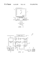
- FIG. 1 is a block diagram of a system according to the present invention.
- FIG. 2 is a block diagram of a sensor array according to the present invention.
- FIG. 3 illustrates the physical structure of the individual sensor cells and their electrical operation according to the present invention.
- FIGS. 4A-4C comprise a pictorial illustration of the operation of a system according to the present invention to provide X-Y input to a computer.
- FIGS. 5A-5C comprise a pictorial illustration of the operation of a system according to the present invention to provide Z input to a computer.
- System 11 includes a display 13 which includes a screen 15 .
- a pointer 17 is shown displayed on screen 15 .
- Display 13 may be, for example, a standard CRT computer monitor. Alternatively, screen 13 may operate on any of several non-CRT technologies used in laptop and notebook computers.
- System 11 also includes a processor 18 that includes a central processing unit (CPU) 19 and memory 20 .
- CPU 19 is a microprocessor such as an Intel 166 MHz Pentium Microprocessor.
- Memory 20 includes random access memory (RAM).
- System 11 includes a user input device 21 .
- user input device 21 is represented generally as a rectangle.
- the specific form of user input device 21 is determined by the configuration of the system.
- the user input device may be integrated into the body of a laptop or notebook computer, or it may be part of a hand-held infrared remote control device.
- User input device 21 includes a sensing element 23 .
- sensing element 23 senses movement of the user's thumb or finger, shown in phantom and designated by the numeral 25 , to control the X-Y position of pointer 17 on screen 15 .
- sensing element 23 also senses the placing or lifting of a finger on sensing element 23 or changes in finger pressure on sensing element 23 to provide Z input to microprocessor 19 .
- Z input may be interpreted as mouse button up and mouse button down signals.
- Z input may be interpreted as driving pointer 17 into a three dimensional graphical user interface displayed on screen 15 .
- User input device 21 is preferably integrated into a single chip, and it includes an array 27 of cells 29 .
- Array 27 comprises M rows and N columns. The number of rows M and columns N may or may not be the same.
- each cell 29 is smaller than the width of a fingerprint ridge, and in the preferred embodiment, cells 29 are on a pitch of 50 micrometers, which corresponds to a resolution of about 508 dots per inch.
- Device 21 includes a horizontal scanning stage 31 and a vertical scanning stage 33 . Scanning stages 31 and 33 enable one cell 29 at a time according to a predetermined scanning pattern.
- Input device 21 includes a power supply and scan control unit 35 .
- Power supply and scan control unit 35 supplies a reference voltage to each cell 29 of array 27 .
- Power supply and scan control unit 35 also operates scanning stages 31 and 33 to produce the desired scanning of cells 29 .
- An A/D converter 37 is connected to receive the output of each cell 29 of array 27 .
- the output of each cell 29 is a voltage that represents a gray scale value for the pixel defined by the cell.
- A/D converter 37 converts the voltage into an eight bit numerical gray scale value.
- the output of A/D converter 37 is connected to output logic 39 , which processes the output of A/D converter 37 to capture successive images.
- the successive images comprise arrays of pixels with each pixel having a gray scale value from zero to 255.
- the successive images are processed, preferably in microprocessor 19 , to provide X-Y, and Z inputs to microprocessor 19 .
- Each cell 29 includes a first capacitor plate 47 and a second capacitor plate 49 supported on a semiconductor substrate, which is preferably a conventional silicon substrate that may have a conventional shallow epitaxial layer defining an upper surface region thereof.
- the top surface of the substrate includes an insulating layer 41 .
- Insulating layer 41 is preferably an oxide layer, which may be a conventional thermally grown silicon dioxide layer.
- Conductor plates 47 and 49 are covered by a protective coating 51 of a hard material. Protective coating 51 protects sensor 29 from abrasion, contamination, and electrostatic discharge.
- Each cell 29 includes a high gain inverting amplifier 53 .
- the input of inverter 53 is connected to a reference voltage source V REF through an input capacitor 54 .
- the output of inverter 53 is connected to an output V OUT .
- the input of inverter 53 is connected to conductor plate 47 and the output of inverter 53 is connected to conductor plate 49 , thereby creating a charge integrator whose feedback capacitance is the effective capacitance between conductor plates 47 and 49 .
- the upper surface of the skin over each sensor acts as a third capacitor plate separated from adjacent conductor plates 47 and 49 by a dielectric layer that includes protective coating 51 and a variable thickness of air. Because fingerprint valleys 55 will be farther from conductor plates 47 and 49 than finger ridges 57 , sensors beneath valleys will have more distance between their capacitor plates 47 and 49 and the skin surface than sensors under ridges 57 . The thickness of this dielectric layer will modulate the capacitance coupling between plates 47 and 49 of each cell 29 . Accordingly, sensors 29 under valleys will exhibit a different effective capacitance than sensors 29 under ridges. As shown in FIG. 3, the effective capacitance of sensor 29 a is different from the effective capacitance of sensor 29 b.
- Sensors 29 work in two phases.
- the charge integrator is reset with a switch 59 by shorting the input and output of inverter 53 . This causes inverter 53 to settle to its logical threshold.
- a fixed charge is input to the charge integrator, causing an output voltage swing inversely proportional to the feedback capacitance, which is the effective capacitance between conductor plates 47 and 49 .
- the output of inverter 53 will range between two extremes depending on the effective feedback capacitance value. The first extreme is a saturated voltage level if the effective feedback capacitance is very small.
- the second extreme is a voltage close to the logical threshold, which is the reset value, when the effective feedback capacitance is large. Since the distance between the skin and the sensor changes the effective feedback capacitance of the charge integrator, the output of sensor 29 A under ridge 57 will be different from the output of sensor 29 B under valley 55 .
- FIGS. 4A-4C The operation of the system of the present invention to control the X-Y position of pointer 17 on screen 15 is illustrated with respect to FIGS. 4A-4C.
- an image 61 a is captured by sensing element 23 at an initial time T 0 .
- Image 61 a includes a portion 63 a , which is an image of a portion of a user's fingertip.
- the pixels of portion 63 a have numerical gray scale values greater than zero.
- the remainder 65 a of image 61 a comprises a plurality of pixels having numerical gray scale values substantially equal to zero.
- image 61 a is stored at a first memory location in microprocessor 19 .
- image 61 b which is captured at a second time T 1 .
- Image 61 b includes a portion 63 b , which is the image of the user's fingertip at time T 1 .
- image 63 b comprises a plurality of pixels having positive gray scale values.
- the remainder of 65 b of image 61 b again comprises a plurality of pixels having a gray scale values substantially equal to zero.
- image 61 b is stored at a second memory location in microprocessor 19 .
- X-Y input is based upon the displacement of portion 63 b of FIG. 4B with respect to portion 63 a of FIG. 4 A.
- image 61 a is subtracted from image 61 b to form a composite image 67 illustrated in FIG. 4 C. Since the pixels of images 61 a and 61 b have gray scale values equal to or greater than zero, preferably ranging from zero to 255, subtracting image 61 a from image 61 b results in a composite image having gray scale values ranging from ⁇ 255 to +255.
- three regions can be identified, i.e.
- composite image 67 includes a negative region 69 and a positive region 71 .
- Composite image 67 also has regions 73 and 75 which have substantially zero gray scale values. The range around zero is used to filter out the background pixels. The difference computation with the range around zero is also used to overcome the “fixed pattern noise” problem, which is connected to oxide variation, and the presence of humidity or faulty cells.
- the magnitude and direction of the finger position displacement is determined by computing the centroid 77 of positive region 71 and the centroid 79 of negative region 69 of composite image 67 .
- n is the area of or number of pixels in the region and the index i extends only to the region considered.
- the displacement of centroid 77 with respect to centroid 79 is indicated by a displacement vector 81 .
- Displacement vector 81 is the difference between the coordinates of centroids 77 and 79 .
- the displacement vector, or a velocity vector obtained by dividing the displacement vector by the time between T 0 and T 1 is input to pointer control software in microprocessor 19 , thereby to control the position of pointer 17 on screen 15 .
- FIGS. 5A-5C there is illustrated the operation of the present invention in processing Z input.
- an image 83 a is captured at a first time T 0 .
- Image 83 a includes a portion 85 a which comprises a plurality of pixels having positive gray scale values.
- the remaining portion 87 a of image 83 a comprises pixels having gray scale values substantially equal to zero.
- FIG. 5B there is shown an image 83 b captured at a second time T 1 .
- Image 83 b includes a portion 85 b and a remaining portion 87 b . It will be observed that portion 85 b of image 83 b is larger than portion 85 a of image 83 a , which indicates that the user has increased fingertip pressure on sensor 23 .
- image 83 a is stored at a first memory location and image 83 a is stored at a second memory location.
- Image 83 a is then subtracted from image 83 b to form a composite image 89 , which is illustrated in FIG. 5 C.
- Composite image 89 includes a region 91 , which comprises pixels having positive gray scale values.
- Composite image 89 also includes regions 93 and 95 , each comprising pixels having gray scale values substantially equal to zero.
- FIGS. 5A and 5B there has been substantially no X-Y movement of the user's fingertip. Accordingly, there is no negative region in composite image 89 .
- the present invention computes Z displacement by comparing the areas of the positive and negative regions of composite image 89 . If the positive region is larger than the negative region, as shown in FIG. 5C in which there is no negative region, then a positive Z displacement is indicated. Alternatively, if the negative region in the composite image is larger than the positive region, then a negative Z displacement is indicated. It will be noted with respect to FIG. 4C, that positive region 71 and negative region 69 are of substantially the same area, which indicates no Z displacement.
- N p is the number of positive pixels and N N is the number of negative pixels.
- N p is the number of positive pixels and N N is the number of negative pixels.
- the Z displacement is +1.
- a positive Z displacement is interpreted as a mouse button down input and a negative Z displacement is interpreted as a mouse button up input.
- the system moves the image captured at time T 1 into the first memory location, captures an image at a time T 2 , and stores the captured image in the second memory location.
- the system repeats the steps of the method of the present invention to provide X-Y and Z input to the computer system.
- the present invention provides an efficient system and method for providing user input to a computer or the like. While the present invention has been illustrated and described with respect to a presently preferred embodiment, those skilled in the art, given the benefit of this disclosure, will recognize alternative embodiments. Additionally, certain features of the invention may be used independently of other features. For example, the X-Y input feature and the Z input feature may be implemented separately, all as would be apparent to one skilled in the art.
Abstract
Description


Claims (20)
Priority Applications (1)
| Application Number | Priority Date | Filing Date | Title |
|---|---|---|---|
| US09/151,558 US6292173B1 (en) | 1998-09-11 | 1998-09-11 | Touchpad computer input system and method |
Applications Claiming Priority (1)
| Application Number | Priority Date | Filing Date | Title |
|---|---|---|---|
| US09/151,558 US6292173B1 (en) | 1998-09-11 | 1998-09-11 | Touchpad computer input system and method |
Publications (1)
| Publication Number | Publication Date |
|---|---|
| US6292173B1 true US6292173B1 (en) | 2001-09-18 |
Family
ID=22539305
Family Applications (1)
| Application Number | Title | Priority Date | Filing Date |
|---|---|---|---|
| US09/151,558 Expired - Lifetime US6292173B1 (en) | 1998-09-11 | 1998-09-11 | Touchpad computer input system and method |
Country Status (1)
| Country | Link |
|---|---|
| US (1) | US6292173B1 (en) |
Cited By (35)
| Publication number | Priority date | Publication date | Assignee | Title |
|---|---|---|---|---|
| US20030085882A1 (en) * | 2001-11-08 | 2003-05-08 | Koninklijke Philips Electronics N.V. | Multi-point touch pad |
| US20030122779A1 (en) * | 2001-11-01 | 2003-07-03 | Martin Kenneth M. | Method and apparatus for providing tactile sensations |
| US20030146899A1 (en) * | 2002-02-06 | 2003-08-07 | Fujitsu Component Limited | Input device and pointer control method |
| US20030222856A1 (en) * | 2002-01-29 | 2003-12-04 | Fedorak Mark V. | Computer pointer control |
| US20040239648A1 (en) * | 2003-05-30 | 2004-12-02 | Abdallah David S. | Man-machine interface for controlling access to electronic devices |
| US20050028112A1 (en) * | 2003-07-30 | 2005-02-03 | Canon Kabushiki Kaisha | Reduced image production method and apparatus |
| US20050046621A1 (en) * | 2003-08-29 | 2005-03-03 | Nokia Corporation | Method and device for recognizing a dual point user input on a touch based user input device |
| US6871242B1 (en) * | 1999-03-31 | 2005-03-22 | International Business Machines Corporation | Personal computer with a biometric sensor having improved resistance to environmental distortions |
| US20050264541A1 (en) * | 2001-03-26 | 2005-12-01 | Mitsuru Satoh | Information input/output apparatus, information input/output control method, and computer product |
| US20070046647A1 (en) * | 2005-08-30 | 2007-03-01 | Nintendo Co., Ltd. | Input data processing program and information processing apparatus |
| US20080062169A1 (en) * | 2004-08-02 | 2008-03-13 | Koninklijke Philips Electronics, N.V. | Method Of Enabling To Model Virtual Objects |
| US20080252617A1 (en) * | 2006-11-06 | 2008-10-16 | Toshiba Matsushita Display Technology Co., Ltd. | Display apparatus with optical input function |
| US20080284754A1 (en) * | 2007-05-15 | 2008-11-20 | High Tech Computer, Corp. | Method for operating user interface and recording medium for storing program applying the same |
| US20090009195A1 (en) * | 2007-07-03 | 2009-01-08 | Cypress Semiconductor Corporation | Method for improving scan time and sensitivity in touch sensitive user interface device |
| US20090085881A1 (en) * | 2007-09-28 | 2009-04-02 | Microsoft Corporation | Detecting finger orientation on a touch-sensitive device |
| US20090153374A1 (en) * | 2005-08-01 | 2009-06-18 | Wai-Lin Maw | Virtual keypad input device |
| US20090278805A1 (en) * | 2007-05-15 | 2009-11-12 | High Tech Computer, Corp. | Electronic device with switchable user interface and electronic device with accessible touch operation |
| US20100020037A1 (en) * | 2008-07-25 | 2010-01-28 | Tomoya Narita | Information processing apparatus and information processing method |
| US20100090712A1 (en) * | 2008-10-15 | 2010-04-15 | Synaptics Incorporated | Sensor device and method with at surface object sensing and away from surface object sensing |
| US20110025629A1 (en) * | 2009-07-28 | 2011-02-03 | Cypress Semiconductor Corporation | Dynamic Mode Switching for Fast Touch Response |
| US8723825B2 (en) | 2009-07-28 | 2014-05-13 | Cypress Semiconductor Corporation | Predictive touch surface scanning |
| US8723827B2 (en) | 2009-07-28 | 2014-05-13 | Cypress Semiconductor Corporation | Predictive touch surface scanning |
| US8929619B2 (en) | 2011-01-26 | 2015-01-06 | Synaptics Incorporated | System and method of image reconstruction with dual line scanner using line counts |
| US8943580B2 (en) | 2007-09-24 | 2015-01-27 | Apple Inc. | Embedded authentication systems in an electronic device |
| USD737288S1 (en) * | 2007-03-22 | 2015-08-25 | Fujifilm Corporation | Electronic camera |
| US9166621B2 (en) | 2006-11-14 | 2015-10-20 | Cypress Semiconductor Corporation | Capacitance to code converter with sigma-delta modulator |
| US9582178B2 (en) | 2011-11-07 | 2017-02-28 | Immersion Corporation | Systems and methods for multi-pressure interaction on touch-sensitive surfaces |
| US9847999B2 (en) | 2016-05-19 | 2017-12-19 | Apple Inc. | User interface for a device requesting remote authorization |
| US9891709B2 (en) | 2012-05-16 | 2018-02-13 | Immersion Corporation | Systems and methods for content- and context specific haptic effects using predefined haptic effects |
| US9898642B2 (en) | 2013-09-09 | 2018-02-20 | Apple Inc. | Device, method, and graphical user interface for manipulating user interfaces based on fingerprint sensor inputs |
| US9904394B2 (en) | 2013-03-13 | 2018-02-27 | Immerson Corporation | Method and devices for displaying graphical user interfaces based on user contact |
| US10142835B2 (en) | 2011-09-29 | 2018-11-27 | Apple Inc. | Authentication with secondary approver |
| US10395128B2 (en) | 2017-09-09 | 2019-08-27 | Apple Inc. | Implementation of biometric authentication |
| US10484384B2 (en) | 2011-09-29 | 2019-11-19 | Apple Inc. | Indirect authentication |
| US11209961B2 (en) | 2012-05-18 | 2021-12-28 | Apple Inc. | Device, method, and graphical user interface for manipulating user interfaces based on fingerprint sensor inputs |
Citations (17)
| Publication number | Priority date | Publication date | Assignee | Title |
|---|---|---|---|---|
| US4353056A (en) * | 1980-06-05 | 1982-10-05 | Siemens Corporation | Capacitive fingerprint sensor |
| US5115475A (en) * | 1990-06-04 | 1992-05-19 | Motorola, Inc. | Automatic semiconductor package inspection method |
| US5168531A (en) * | 1991-06-27 | 1992-12-01 | Digital Equipment Corporation | Real-time recognition of pointing information from video |
| US5239292A (en) * | 1988-10-04 | 1993-08-24 | Crosfield Electronics Ltd. | Computer graphics system electronically simulating painting on canvas |
| US5325442A (en) * | 1990-05-18 | 1994-06-28 | U.S. Philips Corporation | Fingerprint sensing device and recognition system having predetermined electrode activation |
| US5463388A (en) * | 1993-01-29 | 1995-10-31 | At&T Ipm Corp. | Computer mouse or keyboard input device utilizing capacitive sensors |
| US5483601A (en) * | 1992-02-10 | 1996-01-09 | Keith Faulkner | Apparatus and method for biometric identification using silhouette and displacement images of a portion of a person's hand |
| US5483261A (en) * | 1992-02-14 | 1996-01-09 | Itu Research, Inc. | Graphical input controller and method with rear screen image detection |
| US5488204A (en) * | 1992-06-08 | 1996-01-30 | Synaptics, Incorporated | Paintbrush stylus for capacitive touch sensor pad |
| US5543588A (en) * | 1992-06-08 | 1996-08-06 | Synaptics, Incorporated | Touch pad driven handheld computing device |
| US5543591A (en) * | 1992-06-08 | 1996-08-06 | Synaptics, Incorporated | Object position detector with edge motion feature and gesture recognition |
| US5687333A (en) * | 1994-03-31 | 1997-11-11 | Kabushiki Kaisha Toshiba | Information service system responsive to user's pointing manipulation |
| US5799098A (en) * | 1994-10-20 | 1998-08-25 | Calspan Corporation | Fingerprint identification system |
| US5825352A (en) * | 1996-01-04 | 1998-10-20 | Logitech, Inc. | Multiple fingers contact sensing method for emulating mouse buttons and mouse operations on a touch sensor pad |
| US5943043A (en) * | 1995-11-09 | 1999-08-24 | International Business Machines Corporation | Touch panel "double-touch" input method and detection apparatus |
| US5963679A (en) * | 1996-01-26 | 1999-10-05 | Harris Corporation | Electric field fingerprint sensor apparatus and related methods |
| US6037882A (en) * | 1997-09-30 | 2000-03-14 | Levy; David H. | Method and apparatus for inputting data to an electronic system |
-
1998
- 1998-09-11 US US09/151,558 patent/US6292173B1/en not_active Expired - Lifetime
Patent Citations (17)
| Publication number | Priority date | Publication date | Assignee | Title |
|---|---|---|---|---|
| US4353056A (en) * | 1980-06-05 | 1982-10-05 | Siemens Corporation | Capacitive fingerprint sensor |
| US5239292A (en) * | 1988-10-04 | 1993-08-24 | Crosfield Electronics Ltd. | Computer graphics system electronically simulating painting on canvas |
| US5325442A (en) * | 1990-05-18 | 1994-06-28 | U.S. Philips Corporation | Fingerprint sensing device and recognition system having predetermined electrode activation |
| US5115475A (en) * | 1990-06-04 | 1992-05-19 | Motorola, Inc. | Automatic semiconductor package inspection method |
| US5168531A (en) * | 1991-06-27 | 1992-12-01 | Digital Equipment Corporation | Real-time recognition of pointing information from video |
| US5483601A (en) * | 1992-02-10 | 1996-01-09 | Keith Faulkner | Apparatus and method for biometric identification using silhouette and displacement images of a portion of a person's hand |
| US5483261A (en) * | 1992-02-14 | 1996-01-09 | Itu Research, Inc. | Graphical input controller and method with rear screen image detection |
| US5488204A (en) * | 1992-06-08 | 1996-01-30 | Synaptics, Incorporated | Paintbrush stylus for capacitive touch sensor pad |
| US5543588A (en) * | 1992-06-08 | 1996-08-06 | Synaptics, Incorporated | Touch pad driven handheld computing device |
| US5543591A (en) * | 1992-06-08 | 1996-08-06 | Synaptics, Incorporated | Object position detector with edge motion feature and gesture recognition |
| US5463388A (en) * | 1993-01-29 | 1995-10-31 | At&T Ipm Corp. | Computer mouse or keyboard input device utilizing capacitive sensors |
| US5687333A (en) * | 1994-03-31 | 1997-11-11 | Kabushiki Kaisha Toshiba | Information service system responsive to user's pointing manipulation |
| US5799098A (en) * | 1994-10-20 | 1998-08-25 | Calspan Corporation | Fingerprint identification system |
| US5943043A (en) * | 1995-11-09 | 1999-08-24 | International Business Machines Corporation | Touch panel "double-touch" input method and detection apparatus |
| US5825352A (en) * | 1996-01-04 | 1998-10-20 | Logitech, Inc. | Multiple fingers contact sensing method for emulating mouse buttons and mouse operations on a touch sensor pad |
| US5963679A (en) * | 1996-01-26 | 1999-10-05 | Harris Corporation | Electric field fingerprint sensor apparatus and related methods |
| US6037882A (en) * | 1997-09-30 | 2000-03-14 | Levy; David H. | Method and apparatus for inputting data to an electronic system |
Cited By (105)
| Publication number | Priority date | Publication date | Assignee | Title |
|---|---|---|---|---|
| US6871242B1 (en) * | 1999-03-31 | 2005-03-22 | International Business Machines Corporation | Personal computer with a biometric sensor having improved resistance to environmental distortions |
| US7176904B2 (en) * | 2001-03-26 | 2007-02-13 | Ricoh Company, Limited | Information input/output apparatus, information input/output control method, and computer product |
| US20050264541A1 (en) * | 2001-03-26 | 2005-12-01 | Mitsuru Satoh | Information input/output apparatus, information input/output control method, and computer product |
| US7808488B2 (en) | 2001-11-01 | 2010-10-05 | Immersion Corporation | Method and apparatus for providing tactile sensations |
| US8159461B2 (en) | 2001-11-01 | 2012-04-17 | Immersion Corporation | Method and apparatus for providing tactile sensations |
| US8773356B2 (en) | 2001-11-01 | 2014-07-08 | Immersion Corporation | Method and apparatus for providing tactile sensations |
| US7336260B2 (en) * | 2001-11-01 | 2008-02-26 | Immersion Corporation | Method and apparatus for providing tactile sensations |
| US20070229455A1 (en) * | 2001-11-01 | 2007-10-04 | Immersion Corporation | Method and Apparatus for Providing Tactile Sensations |
| US20030122779A1 (en) * | 2001-11-01 | 2003-07-03 | Martin Kenneth M. | Method and apparatus for providing tactile sensations |
| US20030085882A1 (en) * | 2001-11-08 | 2003-05-08 | Koninklijke Philips Electronics N.V. | Multi-point touch pad |
| US6995752B2 (en) * | 2001-11-08 | 2006-02-07 | Koninklijke Philips Electronics N.V. | Multi-point touch pad |
| US20030222856A1 (en) * | 2002-01-29 | 2003-12-04 | Fedorak Mark V. | Computer pointer control |
| US7109975B2 (en) | 2002-01-29 | 2006-09-19 | Meta4Hand Inc. | Computer pointer control |
| US20030146899A1 (en) * | 2002-02-06 | 2003-08-07 | Fujitsu Component Limited | Input device and pointer control method |
| US6937226B2 (en) * | 2002-02-06 | 2005-08-30 | Fujitsu Component Limited | Input device and pointer control method |
| US7420546B2 (en) * | 2003-05-30 | 2008-09-02 | Privaris, Inc. | Man-machine interface for controlling access to electronic devices |
| US7525537B2 (en) * | 2003-05-30 | 2009-04-28 | Privaris, Inc. | Man-machine interface for controlling access to electronic devices |
| US20040239648A1 (en) * | 2003-05-30 | 2004-12-02 | Abdallah David S. | Man-machine interface for controlling access to electronic devices |
| US20050093834A1 (en) * | 2003-05-30 | 2005-05-05 | Abdallah David S. | Man-machine interface for controlling access to electronic devices |
| WO2004109454A2 (en) * | 2003-05-30 | 2004-12-16 | Privaris, Inc. | A man-machine interface for controlling access to electronic devices |
| USRE42038E1 (en) | 2003-05-30 | 2011-01-18 | Privaris, Inc. | Man-machine interface for controlling access to electronic devices |
| WO2004109454A3 (en) * | 2003-05-30 | 2005-01-27 | Privaris Inc | A man-machine interface for controlling access to electronic devices |
| US7688314B2 (en) * | 2003-05-30 | 2010-03-30 | Privaris, Inc. | Man-machine interface for controlling access to electronic devices |
| US20090213087A1 (en) * | 2003-05-30 | 2009-08-27 | Abdallah David S | Man-machine interface for controlling access to electronic devices |
| US20080317302A1 (en) * | 2003-05-30 | 2008-12-25 | Abdallah David S | Man-machine interface for controlling access to electronic devices |
| US9342674B2 (en) | 2003-05-30 | 2016-05-17 | Apple Inc. | Man-machine interface for controlling access to electronic devices |
| US7324087B2 (en) * | 2003-07-30 | 2008-01-29 | Canon Kabushiki Kaisha | Reduced image production method and apparatus |
| US20050028112A1 (en) * | 2003-07-30 | 2005-02-03 | Canon Kabushiki Kaisha | Reduced image production method and apparatus |
| US20100259499A1 (en) * | 2003-08-29 | 2010-10-14 | Terho Kaikuranta | Method and device for recognizing a dual point user input on a touch based user input device |
| US20050046621A1 (en) * | 2003-08-29 | 2005-03-03 | Nokia Corporation | Method and device for recognizing a dual point user input on a touch based user input device |
| US20080062169A1 (en) * | 2004-08-02 | 2008-03-13 | Koninklijke Philips Electronics, N.V. | Method Of Enabling To Model Virtual Objects |
| US20090153374A1 (en) * | 2005-08-01 | 2009-06-18 | Wai-Lin Maw | Virtual keypad input device |
| US8780052B2 (en) | 2005-08-30 | 2014-07-15 | Nintendo Co., Ltd. | Input data processing program and information processing apparatus |
| US20070046647A1 (en) * | 2005-08-30 | 2007-03-01 | Nintendo Co., Ltd. | Input data processing program and information processing apparatus |
| EP1760571A3 (en) * | 2005-08-30 | 2012-04-04 | Nintendo Co., Ltd. | Input data processing program and information processing apparatus |
| EP1760571A2 (en) * | 2005-08-30 | 2007-03-07 | Nintendo Co., Limited | Input data processing program and information processing apparatus |
| US20080252617A1 (en) * | 2006-11-06 | 2008-10-16 | Toshiba Matsushita Display Technology Co., Ltd. | Display apparatus with optical input function |
| US7924273B2 (en) * | 2006-11-06 | 2011-04-12 | Toshiba Matsushita Display Technology Co., Ltd. | Display apparatus with optical input function |
| US9166621B2 (en) | 2006-11-14 | 2015-10-20 | Cypress Semiconductor Corporation | Capacitance to code converter with sigma-delta modulator |
| USD737288S1 (en) * | 2007-03-22 | 2015-08-25 | Fujifilm Corporation | Electronic camera |
| US8456442B2 (en) * | 2007-05-15 | 2013-06-04 | Htc Corporation | Electronic device with switchable user interface and electronic device with accessible touch operation |
| US20090278805A1 (en) * | 2007-05-15 | 2009-11-12 | High Tech Computer, Corp. | Electronic device with switchable user interface and electronic device with accessible touch operation |
| US20080284754A1 (en) * | 2007-05-15 | 2008-11-20 | High Tech Computer, Corp. | Method for operating user interface and recording medium for storing program applying the same |
| US8487883B2 (en) * | 2007-05-15 | 2013-07-16 | Htc Corporation | Method for operating user interface and recording medium for storing program applying the same |
| US20090009195A1 (en) * | 2007-07-03 | 2009-01-08 | Cypress Semiconductor Corporation | Method for improving scan time and sensitivity in touch sensitive user interface device |
| US8508244B2 (en) * | 2007-07-03 | 2013-08-13 | Cypress Semiconductor Corporation | Method for improving scan time and sensitivity in touch sensitive user interface device |
| US9482559B2 (en) | 2007-07-03 | 2016-11-01 | Parade Technologies, Ltd. | Method for improving scan time and sensitivity in touch sensitive user interface device |
| US11468155B2 (en) | 2007-09-24 | 2022-10-11 | Apple Inc. | Embedded authentication systems in an electronic device |
| US8943580B2 (en) | 2007-09-24 | 2015-01-27 | Apple Inc. | Embedded authentication systems in an electronic device |
| US9250795B2 (en) | 2007-09-24 | 2016-02-02 | Apple Inc. | Embedded authentication systems in an electronic device |
| US9519771B2 (en) | 2007-09-24 | 2016-12-13 | Apple Inc. | Embedded authentication systems in an electronic device |
| US9495531B2 (en) | 2007-09-24 | 2016-11-15 | Apple Inc. | Embedded authentication systems in an electronic device |
| US9953152B2 (en) | 2007-09-24 | 2018-04-24 | Apple Inc. | Embedded authentication systems in an electronic device |
| US10275585B2 (en) | 2007-09-24 | 2019-04-30 | Apple Inc. | Embedded authentication systems in an electronic device |
| US10956550B2 (en) | 2007-09-24 | 2021-03-23 | Apple Inc. | Embedded authentication systems in an electronic device |
| US9329771B2 (en) | 2007-09-24 | 2016-05-03 | Apple Inc | Embedded authentication systems in an electronic device |
| US9038167B2 (en) | 2007-09-24 | 2015-05-19 | Apple Inc. | Embedded authentication systems in an electronic device |
| US9304624B2 (en) | 2007-09-24 | 2016-04-05 | Apple Inc. | Embedded authentication systems in an electronic device |
| US9274647B2 (en) | 2007-09-24 | 2016-03-01 | Apple Inc. | Embedded authentication systems in an electronic device |
| US9128601B2 (en) | 2007-09-24 | 2015-09-08 | Apple Inc. | Embedded authentication systems in an electronic device |
| US9134896B2 (en) | 2007-09-24 | 2015-09-15 | Apple Inc. | Embedded authentication systems in an electronic device |
| CN101809880A (en) * | 2007-09-28 | 2010-08-18 | 微软公司 | Detecting finger orientation on a touch-sensitive device |
| US8125458B2 (en) * | 2007-09-28 | 2012-02-28 | Microsoft Corporation | Detecting finger orientation on a touch-sensitive device |
| CN101809880B (en) * | 2007-09-28 | 2013-06-19 | 微软公司 | Detecting finger orientation on a touch-sensitive device |
| US20090085881A1 (en) * | 2007-09-28 | 2009-04-02 | Microsoft Corporation | Detecting finger orientation on a touch-sensitive device |
| US20100020037A1 (en) * | 2008-07-25 | 2010-01-28 | Tomoya Narita | Information processing apparatus and information processing method |
| US9442601B2 (en) * | 2008-07-25 | 2016-09-13 | Sony Corporation | Information processing apparatus and information processing method |
| US20100090712A1 (en) * | 2008-10-15 | 2010-04-15 | Synaptics Incorporated | Sensor device and method with at surface object sensing and away from surface object sensing |
| US8330474B2 (en) * | 2008-10-15 | 2012-12-11 | Synaptics Incorporated | Sensor device and method with at surface object sensing and away from surface object sensing |
| US9007342B2 (en) | 2009-07-28 | 2015-04-14 | Cypress Semiconductor Corporation | Dynamic mode switching for fast touch response |
| US20110025629A1 (en) * | 2009-07-28 | 2011-02-03 | Cypress Semiconductor Corporation | Dynamic Mode Switching for Fast Touch Response |
| US8723827B2 (en) | 2009-07-28 | 2014-05-13 | Cypress Semiconductor Corporation | Predictive touch surface scanning |
| US8723825B2 (en) | 2009-07-28 | 2014-05-13 | Cypress Semiconductor Corporation | Predictive touch surface scanning |
| US9417728B2 (en) | 2009-07-28 | 2016-08-16 | Parade Technologies, Ltd. | Predictive touch surface scanning |
| US9069405B2 (en) | 2009-07-28 | 2015-06-30 | Cypress Semiconductor Corporation | Dynamic mode switching for fast touch response |
| US8929619B2 (en) | 2011-01-26 | 2015-01-06 | Synaptics Incorporated | System and method of image reconstruction with dual line scanner using line counts |
| US10516997B2 (en) | 2011-09-29 | 2019-12-24 | Apple Inc. | Authentication with secondary approver |
| US10419933B2 (en) | 2011-09-29 | 2019-09-17 | Apple Inc. | Authentication with secondary approver |
| US11755712B2 (en) | 2011-09-29 | 2023-09-12 | Apple Inc. | Authentication with secondary approver |
| US10142835B2 (en) | 2011-09-29 | 2018-11-27 | Apple Inc. | Authentication with secondary approver |
| US11200309B2 (en) | 2011-09-29 | 2021-12-14 | Apple Inc. | Authentication with secondary approver |
| US10484384B2 (en) | 2011-09-29 | 2019-11-19 | Apple Inc. | Indirect authentication |
| US10152131B2 (en) | 2011-11-07 | 2018-12-11 | Immersion Corporation | Systems and methods for multi-pressure interaction on touch-sensitive surfaces |
| US9582178B2 (en) | 2011-11-07 | 2017-02-28 | Immersion Corporation | Systems and methods for multi-pressure interaction on touch-sensitive surfaces |
| US10775895B2 (en) | 2011-11-07 | 2020-09-15 | Immersion Corporation | Systems and methods for multi-pressure interaction on touch-sensitive surfaces |
| US9891709B2 (en) | 2012-05-16 | 2018-02-13 | Immersion Corporation | Systems and methods for content- and context specific haptic effects using predefined haptic effects |
| US11209961B2 (en) | 2012-05-18 | 2021-12-28 | Apple Inc. | Device, method, and graphical user interface for manipulating user interfaces based on fingerprint sensor inputs |
| US9904394B2 (en) | 2013-03-13 | 2018-02-27 | Immerson Corporation | Method and devices for displaying graphical user interfaces based on user contact |
| US11287942B2 (en) | 2013-09-09 | 2022-03-29 | Apple Inc. | Device, method, and graphical user interface for manipulating user interfaces |
| US10410035B2 (en) | 2013-09-09 | 2019-09-10 | Apple Inc. | Device, method, and graphical user interface for manipulating user interfaces based on fingerprint sensor inputs |
| US11768575B2 (en) | 2013-09-09 | 2023-09-26 | Apple Inc. | Device, method, and graphical user interface for manipulating user interfaces based on unlock inputs |
| US10055634B2 (en) | 2013-09-09 | 2018-08-21 | Apple Inc. | Device, method, and graphical user interface for manipulating user interfaces based on fingerprint sensor inputs |
| US11494046B2 (en) | 2013-09-09 | 2022-11-08 | Apple Inc. | Device, method, and graphical user interface for manipulating user interfaces based on unlock inputs |
| US10262182B2 (en) | 2013-09-09 | 2019-04-16 | Apple Inc. | Device, method, and graphical user interface for manipulating user interfaces based on unlock inputs |
| US9898642B2 (en) | 2013-09-09 | 2018-02-20 | Apple Inc. | Device, method, and graphical user interface for manipulating user interfaces based on fingerprint sensor inputs |
| US10372963B2 (en) | 2013-09-09 | 2019-08-06 | Apple Inc. | Device, method, and graphical user interface for manipulating user interfaces based on fingerprint sensor inputs |
| US10334054B2 (en) | 2016-05-19 | 2019-06-25 | Apple Inc. | User interface for a device requesting remote authorization |
| US11206309B2 (en) | 2016-05-19 | 2021-12-21 | Apple Inc. | User interface for remote authorization |
| US9847999B2 (en) | 2016-05-19 | 2017-12-19 | Apple Inc. | User interface for a device requesting remote authorization |
| US10749967B2 (en) | 2016-05-19 | 2020-08-18 | Apple Inc. | User interface for remote authorization |
| US11393258B2 (en) | 2017-09-09 | 2022-07-19 | Apple Inc. | Implementation of biometric authentication |
| US10872256B2 (en) | 2017-09-09 | 2020-12-22 | Apple Inc. | Implementation of biometric authentication |
| US10395128B2 (en) | 2017-09-09 | 2019-08-27 | Apple Inc. | Implementation of biometric authentication |
| US11765163B2 (en) | 2017-09-09 | 2023-09-19 | Apple Inc. | Implementation of biometric authentication |
| US10410076B2 (en) | 2017-09-09 | 2019-09-10 | Apple Inc. | Implementation of biometric authentication |
Similar Documents
| Publication | Publication Date | Title |
|---|---|---|
| US6292173B1 (en) | Touchpad computer input system and method | |
| US6408087B1 (en) | Capacitive semiconductor user input device | |
| US6256022B1 (en) | Low-cost semiconductor user input device | |
| US6392636B1 (en) | Touchpad providing screen cursor/pointer movement control | |
| US5463388A (en) | Computer mouse or keyboard input device utilizing capacitive sensors | |
| US7639234B2 (en) | Capacitive sensing and absolute position mapping in displacement type pointing devices | |
| US7889176B2 (en) | Capacitive sensing in displacement type pointing devices | |
| US7460109B2 (en) | Navigation and fingerprint sensor | |
| US6847354B2 (en) | Three dimensional interactive display | |
| US8005275B2 (en) | Pointer tool | |
| US7324095B2 (en) | Pressure-sensitive input device for data processing systems | |
| EP0422361B1 (en) | Data input device for compact electronic equipments | |
| US7576726B2 (en) | Dual-positioning controller and method for controlling an indicium on a display of an electronic device | |
| US7409107B2 (en) | Input device, information device, and control information generation method | |
| US20120092250A1 (en) | Finger-operated input device | |
| JPH0683523A (en) | Work-surface system and realizing method thereof, sensor utilizing method and person identifying method | |
| US20080042974A1 (en) | System and method for determining cursor speed in a puck-based pointing device | |
| US5883617A (en) | Pointing device with improved cursor control data | |
| JP2004259173A (en) | Pointing device | |
| US20090153484A1 (en) | Mouse and method for cursor control | |
| US9395858B2 (en) | Capacitive finger navigation device with hybrid mode and operating method thereof | |
| KR20180015400A (en) | Semiconductor device | |
| CN112041800A (en) | Fingerprint sensing system and method for providing user input on electronic device using fingerprint sensor |
Legal Events
| Date | Code | Title | Description |
|---|---|---|---|
| AS | Assignment |
Owner name: STMICROELECTRONICS S.R.L., ITALY Free format text: ASSIGNMENT OF ASSIGNORS INTEREST;ASSIGNORS:RAMBALDI, ROBERTO;TARTAGNI, MARCO;VAJNA, ZSOLT MIKLOS KOVACS;AND OTHERS;REEL/FRAME:011716/0946;SIGNING DATES FROM 19990326 TO 19990401 |
|
| STCF | Information on status: patent grant |
Free format text: PATENTED CASE |
|
| AS | Assignment |
Owner name: UPEK, INC., CALIFORNIA Free format text: ASSIGNMENT OF ASSIGNORS INTEREST;ASSIGNORS:STMICROELECTRONICS SRL;STMICROELECTRONICS N.V.;REEL/FRAME:014499/0234 Effective date: 20040304 |
|
| FEPP | Fee payment procedure |
Free format text: PAYOR NUMBER ASSIGNED (ORIGINAL EVENT CODE: ASPN); ENTITY STATUS OF PATENT OWNER: LARGE ENTITY |
|
| FPAY | Fee payment |
Year of fee payment: 4 |
|
| FEPP | Fee payment procedure |
Free format text: PAT HOLDER CLAIMS SMALL ENTITY STATUS, ENTITY STATUS SET TO SMALL (ORIGINAL EVENT CODE: LTOS); ENTITY STATUS OF PATENT OWNER: LARGE ENTITY |
|
| FPAY | Fee payment |
Year of fee payment: 8 |
|
| AS | Assignment |
Owner name: AUTHENTEC, INC., FLORIDA Free format text: ASSIGNMENT OF ASSIGNORS INTEREST;ASSIGNOR:UPEK, INC.;REEL/FRAME:026944/0942 Effective date: 20110901 |
|
| FEPP | Fee payment procedure |
Free format text: PAT HOLDER NO LONGER CLAIMS SMALL ENTITY STATUS, ENTITY STATUS SET TO UNDISCOUNTED (ORIGINAL EVENT CODE: STOL); ENTITY STATUS OF PATENT OWNER: LARGE ENTITY |
|
| AS | Assignment |
Owner name: AUTHENTEC, INC., FLORIDA Free format text: CORRECTIVE ASSIGNMENT TO CORRECT THE ASSIGNMENT DOCUMENT TO IDENTIFY UPEK, INC. AS A DELAWARE CORPORATION PREVIOUSLY RECORDED ON REEL 026944 FRAME 0942. ASSIGNOR(S) HEREBY CONFIRMS THE ASSIGNMENT OF ASSIGNOR'S INTEREST;ASSIGNOR:UPEK, INC.;REEL/FRAME:029074/0347 Effective date: 20121003 |
|
| FPAY | Fee payment |
Year of fee payment: 12 |
|
| AS | Assignment |
Owner name: IDEX ASA, NORWAY Free format text: LICENSE;ASSIGNOR:AUTHENTEC, INC.;REEL/FRAME:030254/0103 Effective date: 20100907 Owner name: IDEX ASA, NORWAY Free format text: LICENSE;ASSIGNOR:APPLE INC.;REEL/FRAME:030254/0110 Effective date: 20121004 |
|
| AS | Assignment |
Owner name: APPLE INC., CALIFORNIA Free format text: ASSIGNMENT OF ASSIGNORS INTEREST;ASSIGNOR:AUTHENTEC, INC.;REEL/FRAME:035552/0286 Effective date: 20130210 |