US6296020B1 - Fluid circuit components based upon passive fluid dynamics - Google Patents
Fluid circuit components based upon passive fluid dynamics Download PDFInfo
- Publication number
- US6296020B1 US6296020B1 US09/417,691 US41769199A US6296020B1 US 6296020 B1 US6296020 B1 US 6296020B1 US 41769199 A US41769199 A US 41769199A US 6296020 B1 US6296020 B1 US 6296020B1
- Authority
- US
- United States
- Prior art keywords
- fluid
- stopping means
- microchannel
- fluid circuit
- passive
- Prior art date
- Legal status (The legal status is an assumption and is not a legal conclusion. Google has not performed a legal analysis and makes no representation as to the accuracy of the status listed.)
- Expired - Fee Related
Links
Images


Classifications
-
- F—MECHANICAL ENGINEERING; LIGHTING; HEATING; WEAPONS; BLASTING
- F15—FLUID-PRESSURE ACTUATORS; HYDRAULICS OR PNEUMATICS IN GENERAL
- F15C—FLUID-CIRCUIT ELEMENTS PREDOMINANTLY USED FOR COMPUTING OR CONTROL PURPOSES
- F15C1/00—Circuit elements having no moving parts
- F15C1/14—Stream-interaction devices; Momentum-exchange devices, e.g. operating by exchange between two orthogonal fluid jets ; Proportional amplifiers
-
- G—PHYSICS
- G01—MEASURING; TESTING
- G01N—INVESTIGATING OR ANALYSING MATERIALS BY DETERMINING THEIR CHEMICAL OR PHYSICAL PROPERTIES
- G01N35/00—Automatic analysis not limited to methods or materials provided for in any single one of groups G01N1/00 - G01N33/00; Handling materials therefor
-
- B—PERFORMING OPERATIONS; TRANSPORTING
- B01—PHYSICAL OR CHEMICAL PROCESSES OR APPARATUS IN GENERAL
- B01F—MIXING, e.g. DISSOLVING, EMULSIFYING OR DISPERSING
- B01F25/00—Flow mixers; Mixers for falling materials, e.g. solid particles
- B01F25/30—Injector mixers
- B01F25/31—Injector mixers in conduits or tubes through which the main component flows
-
- B—PERFORMING OPERATIONS; TRANSPORTING
- B01—PHYSICAL OR CHEMICAL PROCESSES OR APPARATUS IN GENERAL
- B01F—MIXING, e.g. DISSOLVING, EMULSIFYING OR DISPERSING
- B01F25/00—Flow mixers; Mixers for falling materials, e.g. solid particles
- B01F25/40—Static mixers
- B01F25/42—Static mixers in which the mixing is affected by moving the components jointly in changing directions, e.g. in tubes provided with baffles or obstructions
- B01F25/43—Mixing tubes, e.g. wherein the material is moved in a radial or partly reversed direction
- B01F25/432—Mixing tubes, e.g. wherein the material is moved in a radial or partly reversed direction with means for dividing the material flow into separate sub-flows and for repositioning and recombining these sub-flows; Cross-mixing, e.g. conducting the outer layer of the material nearer to the axis of the tube or vice-versa
- B01F25/4321—Mixing tubes, e.g. wherein the material is moved in a radial or partly reversed direction with means for dividing the material flow into separate sub-flows and for repositioning and recombining these sub-flows; Cross-mixing, e.g. conducting the outer layer of the material nearer to the axis of the tube or vice-versa the subflows consisting of at least two flat layers which are recombined, e.g. using means having restriction or expansion zones
- B01F25/43211—Mixing tubes, e.g. wherein the material is moved in a radial or partly reversed direction with means for dividing the material flow into separate sub-flows and for repositioning and recombining these sub-flows; Cross-mixing, e.g. conducting the outer layer of the material nearer to the axis of the tube or vice-versa the subflows consisting of at least two flat layers which are recombined, e.g. using means having restriction or expansion zones using a simple by-pass for separating and recombining the flow, e.g. by using branches of different length
-
- B—PERFORMING OPERATIONS; TRANSPORTING
- B01—PHYSICAL OR CHEMICAL PROCESSES OR APPARATUS IN GENERAL
- B01F—MIXING, e.g. DISSOLVING, EMULSIFYING OR DISPERSING
- B01F33/00—Other mixers; Mixing plants; Combinations of mixers
- B01F33/30—Micromixers
-
- B—PERFORMING OPERATIONS; TRANSPORTING
- B01—PHYSICAL OR CHEMICAL PROCESSES OR APPARATUS IN GENERAL
- B01F—MIXING, e.g. DISSOLVING, EMULSIFYING OR DISPERSING
- B01F35/00—Accessories for mixers; Auxiliary operations or auxiliary devices; Parts or details of general application
- B01F35/71—Feed mechanisms
- B01F35/715—Feeding the components in several steps, e.g. successive steps
-
- B—PERFORMING OPERATIONS; TRANSPORTING
- B01—PHYSICAL OR CHEMICAL PROCESSES OR APPARATUS IN GENERAL
- B01F—MIXING, e.g. DISSOLVING, EMULSIFYING OR DISPERSING
- B01F35/00—Accessories for mixers; Auxiliary operations or auxiliary devices; Parts or details of general application
- B01F35/71—Feed mechanisms
- B01F35/717—Feed mechanisms characterised by the means for feeding the components to the mixer
- B01F35/7172—Feed mechanisms characterised by the means for feeding the components to the mixer using capillary forces
-
- B—PERFORMING OPERATIONS; TRANSPORTING
- B01—PHYSICAL OR CHEMICAL PROCESSES OR APPARATUS IN GENERAL
- B01J—CHEMICAL OR PHYSICAL PROCESSES, e.g. CATALYSIS OR COLLOID CHEMISTRY; THEIR RELEVANT APPARATUS
- B01J19/00—Chemical, physical or physico-chemical processes in general; Their relevant apparatus
- B01J19/0093—Microreactors, e.g. miniaturised or microfabricated reactors
-
- B—PERFORMING OPERATIONS; TRANSPORTING
- B01—PHYSICAL OR CHEMICAL PROCESSES OR APPARATUS IN GENERAL
- B01L—CHEMICAL OR PHYSICAL LABORATORY APPARATUS FOR GENERAL USE
- B01L3/00—Containers or dishes for laboratory use, e.g. laboratory glassware; Droppers
- B01L3/50—Containers for the purpose of retaining a material to be analysed, e.g. test tubes
- B01L3/502—Containers for the purpose of retaining a material to be analysed, e.g. test tubes with fluid transport, e.g. in multi-compartment structures
- B01L3/5027—Containers for the purpose of retaining a material to be analysed, e.g. test tubes with fluid transport, e.g. in multi-compartment structures by integrated microfluidic structures, i.e. dimensions of channels and chambers are such that surface tension forces are important, e.g. lab-on-a-chip
- B01L3/502738—Containers for the purpose of retaining a material to be analysed, e.g. test tubes with fluid transport, e.g. in multi-compartment structures by integrated microfluidic structures, i.e. dimensions of channels and chambers are such that surface tension forces are important, e.g. lab-on-a-chip characterised by integrated valves
-
- F—MECHANICAL ENGINEERING; LIGHTING; HEATING; WEAPONS; BLASTING
- F15—FLUID-PRESSURE ACTUATORS; HYDRAULICS OR PNEUMATICS IN GENERAL
- F15C—FLUID-CIRCUIT ELEMENTS PREDOMINANTLY USED FOR COMPUTING OR CONTROL PURPOSES
- F15C1/00—Circuit elements having no moving parts
- F15C1/14—Stream-interaction devices; Momentum-exchange devices, e.g. operating by exchange between two orthogonal fluid jets ; Proportional amplifiers
- F15C1/146—Stream-interaction devices; Momentum-exchange devices, e.g. operating by exchange between two orthogonal fluid jets ; Proportional amplifiers multiple arrangements thereof, forming counting circuits, sliding registers, integration circuits or the like
-
- B—PERFORMING OPERATIONS; TRANSPORTING
- B01—PHYSICAL OR CHEMICAL PROCESSES OR APPARATUS IN GENERAL
- B01F—MIXING, e.g. DISSOLVING, EMULSIFYING OR DISPERSING
- B01F2101/00—Mixing characterised by the nature of the mixed materials or by the application field
- B01F2101/23—Mixing of laboratory samples e.g. in preparation of analysing or testing properties of materials
-
- B—PERFORMING OPERATIONS; TRANSPORTING
- B01—PHYSICAL OR CHEMICAL PROCESSES OR APPARATUS IN GENERAL
- B01L—CHEMICAL OR PHYSICAL LABORATORY APPARATUS FOR GENERAL USE
- B01L2200/00—Solutions for specific problems relating to chemical or physical laboratory apparatus
- B01L2200/02—Adapting objects or devices to another
- B01L2200/025—Align devices or objects to ensure defined positions relative to each other
-
- B—PERFORMING OPERATIONS; TRANSPORTING
- B01—PHYSICAL OR CHEMICAL PROCESSES OR APPARATUS IN GENERAL
- B01L—CHEMICAL OR PHYSICAL LABORATORY APPARATUS FOR GENERAL USE
- B01L2200/00—Solutions for specific problems relating to chemical or physical laboratory apparatus
- B01L2200/06—Fluid handling related problems
- B01L2200/0621—Control of the sequence of chambers filled or emptied
-
- B—PERFORMING OPERATIONS; TRANSPORTING
- B01—PHYSICAL OR CHEMICAL PROCESSES OR APPARATUS IN GENERAL
- B01L—CHEMICAL OR PHYSICAL LABORATORY APPARATUS FOR GENERAL USE
- B01L2200/00—Solutions for specific problems relating to chemical or physical laboratory apparatus
- B01L2200/06—Fluid handling related problems
- B01L2200/0684—Venting, avoiding backpressure, avoid gas bubbles
-
- B—PERFORMING OPERATIONS; TRANSPORTING
- B01—PHYSICAL OR CHEMICAL PROCESSES OR APPARATUS IN GENERAL
- B01L—CHEMICAL OR PHYSICAL LABORATORY APPARATUS FOR GENERAL USE
- B01L2200/00—Solutions for specific problems relating to chemical or physical laboratory apparatus
- B01L2200/10—Integrating sample preparation and analysis in single entity, e.g. lab-on-a-chip concept
-
- B—PERFORMING OPERATIONS; TRANSPORTING
- B01—PHYSICAL OR CHEMICAL PROCESSES OR APPARATUS IN GENERAL
- B01L—CHEMICAL OR PHYSICAL LABORATORY APPARATUS FOR GENERAL USE
- B01L2200/00—Solutions for specific problems relating to chemical or physical laboratory apparatus
- B01L2200/12—Specific details about manufacturing devices
-
- B—PERFORMING OPERATIONS; TRANSPORTING
- B01—PHYSICAL OR CHEMICAL PROCESSES OR APPARATUS IN GENERAL
- B01L—CHEMICAL OR PHYSICAL LABORATORY APPARATUS FOR GENERAL USE
- B01L2300/00—Additional constructional details
- B01L2300/08—Geometry, shape and general structure
- B01L2300/0861—Configuration of multiple channels and/or chambers in a single devices
- B01L2300/0864—Configuration of multiple channels and/or chambers in a single devices comprising only one inlet and multiple receiving wells, e.g. for separation, splitting
-
- B—PERFORMING OPERATIONS; TRANSPORTING
- B01—PHYSICAL OR CHEMICAL PROCESSES OR APPARATUS IN GENERAL
- B01L—CHEMICAL OR PHYSICAL LABORATORY APPARATUS FOR GENERAL USE
- B01L2300/00—Additional constructional details
- B01L2300/08—Geometry, shape and general structure
- B01L2300/0861—Configuration of multiple channels and/or chambers in a single devices
- B01L2300/0867—Multiple inlets and one sample wells, e.g. mixing, dilution
-
- B—PERFORMING OPERATIONS; TRANSPORTING
- B01—PHYSICAL OR CHEMICAL PROCESSES OR APPARATUS IN GENERAL
- B01L—CHEMICAL OR PHYSICAL LABORATORY APPARATUS FOR GENERAL USE
- B01L2300/00—Additional constructional details
- B01L2300/08—Geometry, shape and general structure
- B01L2300/0861—Configuration of multiple channels and/or chambers in a single devices
- B01L2300/087—Multiple sequential chambers
-
- B—PERFORMING OPERATIONS; TRANSPORTING
- B01—PHYSICAL OR CHEMICAL PROCESSES OR APPARATUS IN GENERAL
- B01L—CHEMICAL OR PHYSICAL LABORATORY APPARATUS FOR GENERAL USE
- B01L2300/00—Additional constructional details
- B01L2300/08—Geometry, shape and general structure
- B01L2300/0861—Configuration of multiple channels and/or chambers in a single devices
- B01L2300/0874—Three dimensional network
-
- B—PERFORMING OPERATIONS; TRANSPORTING
- B01—PHYSICAL OR CHEMICAL PROCESSES OR APPARATUS IN GENERAL
- B01L—CHEMICAL OR PHYSICAL LABORATORY APPARATUS FOR GENERAL USE
- B01L2300/00—Additional constructional details
- B01L2300/08—Geometry, shape and general structure
- B01L2300/0887—Laminated structure
-
- B—PERFORMING OPERATIONS; TRANSPORTING
- B01—PHYSICAL OR CHEMICAL PROCESSES OR APPARATUS IN GENERAL
- B01L—CHEMICAL OR PHYSICAL LABORATORY APPARATUS FOR GENERAL USE
- B01L2300/00—Additional constructional details
- B01L2300/16—Surface properties and coatings
- B01L2300/161—Control and use of surface tension forces, e.g. hydrophobic, hydrophilic
- B01L2300/165—Specific details about hydrophobic, oleophobic surfaces
-
- B—PERFORMING OPERATIONS; TRANSPORTING
- B01—PHYSICAL OR CHEMICAL PROCESSES OR APPARATUS IN GENERAL
- B01L—CHEMICAL OR PHYSICAL LABORATORY APPARATUS FOR GENERAL USE
- B01L2300/00—Additional constructional details
- B01L2300/18—Means for temperature control
-
- B—PERFORMING OPERATIONS; TRANSPORTING
- B01—PHYSICAL OR CHEMICAL PROCESSES OR APPARATUS IN GENERAL
- B01L—CHEMICAL OR PHYSICAL LABORATORY APPARATUS FOR GENERAL USE
- B01L2400/00—Moving or stopping fluids
- B01L2400/04—Moving fluids with specific forces or mechanical means
- B01L2400/0403—Moving fluids with specific forces or mechanical means specific forces
- B01L2400/0406—Moving fluids with specific forces or mechanical means specific forces capillary forces
-
- B—PERFORMING OPERATIONS; TRANSPORTING
- B01—PHYSICAL OR CHEMICAL PROCESSES OR APPARATUS IN GENERAL
- B01L—CHEMICAL OR PHYSICAL LABORATORY APPARATUS FOR GENERAL USE
- B01L2400/00—Moving or stopping fluids
- B01L2400/04—Moving fluids with specific forces or mechanical means
- B01L2400/0475—Moving fluids with specific forces or mechanical means specific mechanical means and fluid pressure
- B01L2400/0487—Moving fluids with specific forces or mechanical means specific mechanical means and fluid pressure fluid pressure, pneumatics
-
- B—PERFORMING OPERATIONS; TRANSPORTING
- B01—PHYSICAL OR CHEMICAL PROCESSES OR APPARATUS IN GENERAL
- B01L—CHEMICAL OR PHYSICAL LABORATORY APPARATUS FOR GENERAL USE
- B01L2400/00—Moving or stopping fluids
- B01L2400/06—Valves, specific forms thereof
- B01L2400/0688—Valves, specific forms thereof surface tension valves, capillary stop, capillary break
-
- B—PERFORMING OPERATIONS; TRANSPORTING
- B01—PHYSICAL OR CHEMICAL PROCESSES OR APPARATUS IN GENERAL
- B01L—CHEMICAL OR PHYSICAL LABORATORY APPARATUS FOR GENERAL USE
- B01L2400/00—Moving or stopping fluids
- B01L2400/06—Valves, specific forms thereof
- B01L2400/0694—Valves, specific forms thereof vents used to stop and induce flow, backpressure valves
-
- B—PERFORMING OPERATIONS; TRANSPORTING
- B01—PHYSICAL OR CHEMICAL PROCESSES OR APPARATUS IN GENERAL
- B01L—CHEMICAL OR PHYSICAL LABORATORY APPARATUS FOR GENERAL USE
- B01L3/00—Containers or dishes for laboratory use, e.g. laboratory glassware; Droppers
- B01L3/50—Containers for the purpose of retaining a material to be analysed, e.g. test tubes
- B01L3/502—Containers for the purpose of retaining a material to be analysed, e.g. test tubes with fluid transport, e.g. in multi-compartment structures
- B01L3/5027—Containers for the purpose of retaining a material to be analysed, e.g. test tubes with fluid transport, e.g. in multi-compartment structures by integrated microfluidic structures, i.e. dimensions of channels and chambers are such that surface tension forces are important, e.g. lab-on-a-chip
- B01L3/50273—Containers for the purpose of retaining a material to be analysed, e.g. test tubes with fluid transport, e.g. in multi-compartment structures by integrated microfluidic structures, i.e. dimensions of channels and chambers are such that surface tension forces are important, e.g. lab-on-a-chip characterised by the means or forces applied to move the fluids
-
- B—PERFORMING OPERATIONS; TRANSPORTING
- B01—PHYSICAL OR CHEMICAL PROCESSES OR APPARATUS IN GENERAL
- B01L—CHEMICAL OR PHYSICAL LABORATORY APPARATUS FOR GENERAL USE
- B01L3/00—Containers or dishes for laboratory use, e.g. laboratory glassware; Droppers
- B01L3/50—Containers for the purpose of retaining a material to be analysed, e.g. test tubes
- B01L3/502—Containers for the purpose of retaining a material to be analysed, e.g. test tubes with fluid transport, e.g. in multi-compartment structures
- B01L3/5027—Containers for the purpose of retaining a material to be analysed, e.g. test tubes with fluid transport, e.g. in multi-compartment structures by integrated microfluidic structures, i.e. dimensions of channels and chambers are such that surface tension forces are important, e.g. lab-on-a-chip
- B01L3/502746—Containers for the purpose of retaining a material to be analysed, e.g. test tubes with fluid transport, e.g. in multi-compartment structures by integrated microfluidic structures, i.e. dimensions of channels and chambers are such that surface tension forces are important, e.g. lab-on-a-chip characterised by the means for controlling flow resistance, e.g. flow controllers, baffles
-
- F—MECHANICAL ENGINEERING; LIGHTING; HEATING; WEAPONS; BLASTING
- F28—HEAT EXCHANGE IN GENERAL
- F28F—DETAILS OF HEAT-EXCHANGE AND HEAT-TRANSFER APPARATUS, OF GENERAL APPLICATION
- F28F2245/00—Coatings; Surface treatments
- F28F2245/04—Coatings; Surface treatments hydrophobic
-
- F—MECHANICAL ENGINEERING; LIGHTING; HEATING; WEAPONS; BLASTING
- F28—HEAT EXCHANGE IN GENERAL
- F28F—DETAILS OF HEAT-EXCHANGE AND HEAT-TRANSFER APPARATUS, OF GENERAL APPLICATION
- F28F2260/00—Heat exchangers or heat exchange elements having special size, e.g. microstructures
- F28F2260/02—Heat exchangers or heat exchange elements having special size, e.g. microstructures having microchannels
-
- G—PHYSICS
- G01—MEASURING; TESTING
- G01N—INVESTIGATING OR ANALYSING MATERIALS BY DETERMINING THEIR CHEMICAL OR PHYSICAL PROPERTIES
- G01N35/00—Automatic analysis not limited to methods or materials provided for in any single one of groups G01N1/00 - G01N33/00; Handling materials therefor
- G01N2035/00178—Special arrangements of analysers
- G01N2035/00237—Handling microquantities of analyte, e.g. microvalves, capillary networks
-
- G—PHYSICS
- G01—MEASURING; TESTING
- G01N—INVESTIGATING OR ANALYSING MATERIALS BY DETERMINING THEIR CHEMICAL OR PHYSICAL PROPERTIES
- G01N35/00—Automatic analysis not limited to methods or materials provided for in any single one of groups G01N1/00 - G01N33/00; Handling materials therefor
- G01N2035/00346—Heating or cooling arrangements
- G01N2035/00356—Holding samples at elevated temperature (incubation)
- G01N2035/00366—Several different temperatures used
-
- G—PHYSICS
- G01—MEASURING; TESTING
- G01N—INVESTIGATING OR ANALYSING MATERIALS BY DETERMINING THEIR CHEMICAL OR PHYSICAL PROPERTIES
- G01N35/00—Automatic analysis not limited to methods or materials provided for in any single one of groups G01N1/00 - G01N33/00; Handling materials therefor
- G01N2035/00465—Separating and mixing arrangements
- G01N2035/00534—Mixing by a special element, e.g. stirrer
- G01N2035/00544—Mixing by a special element, e.g. stirrer using fluid flow
-
- Y—GENERAL TAGGING OF NEW TECHNOLOGICAL DEVELOPMENTS; GENERAL TAGGING OF CROSS-SECTIONAL TECHNOLOGIES SPANNING OVER SEVERAL SECTIONS OF THE IPC; TECHNICAL SUBJECTS COVERED BY FORMER USPC CROSS-REFERENCE ART COLLECTIONS [XRACs] AND DIGESTS
- Y10—TECHNICAL SUBJECTS COVERED BY FORMER USPC
- Y10S—TECHNICAL SUBJECTS COVERED BY FORMER USPC CROSS-REFERENCE ART COLLECTIONS [XRACs] AND DIGESTS
- Y10S366/00—Agitating
- Y10S366/03—Micromixers: variable geometry from the pathway influences mixing/agitation of non-laminar fluid flow
-
- Y—GENERAL TAGGING OF NEW TECHNOLOGICAL DEVELOPMENTS; GENERAL TAGGING OF CROSS-SECTIONAL TECHNOLOGIES SPANNING OVER SEVERAL SECTIONS OF THE IPC; TECHNICAL SUBJECTS COVERED BY FORMER USPC CROSS-REFERENCE ART COLLECTIONS [XRACs] AND DIGESTS
- Y10—TECHNICAL SUBJECTS COVERED BY FORMER USPC
- Y10T—TECHNICAL SUBJECTS COVERED BY FORMER US CLASSIFICATION
- Y10T137/00—Fluid handling
- Y10T137/206—Flow affected by fluid contact, energy field or coanda effect [e.g., pure fluid device or system]
- Y10T137/2076—Utilizing diverse fluids
-
- Y—GENERAL TAGGING OF NEW TECHNOLOGICAL DEVELOPMENTS; GENERAL TAGGING OF CROSS-SECTIONAL TECHNOLOGIES SPANNING OVER SEVERAL SECTIONS OF THE IPC; TECHNICAL SUBJECTS COVERED BY FORMER USPC CROSS-REFERENCE ART COLLECTIONS [XRACs] AND DIGESTS
- Y10—TECHNICAL SUBJECTS COVERED BY FORMER USPC
- Y10T—TECHNICAL SUBJECTS COVERED BY FORMER US CLASSIFICATION
- Y10T137/00—Fluid handling
- Y10T137/206—Flow affected by fluid contact, energy field or coanda effect [e.g., pure fluid device or system]
- Y10T137/2224—Structure of body of device
-
- Y—GENERAL TAGGING OF NEW TECHNOLOGICAL DEVELOPMENTS; GENERAL TAGGING OF CROSS-SECTIONAL TECHNOLOGIES SPANNING OVER SEVERAL SECTIONS OF THE IPC; TECHNICAL SUBJECTS COVERED BY FORMER USPC CROSS-REFERENCE ART COLLECTIONS [XRACs] AND DIGESTS
- Y10—TECHNICAL SUBJECTS COVERED BY FORMER USPC
- Y10T—TECHNICAL SUBJECTS COVERED BY FORMER US CLASSIFICATION
- Y10T137/00—Fluid handling
- Y10T137/206—Flow affected by fluid contact, energy field or coanda effect [e.g., pure fluid device or system]
- Y10T137/2267—Device including passages having V over gamma configuration
Definitions
- This invention deals with the passive control of fluids within a microfluidic circuit.
- the passive control is generated by using the natural forces that exist on a micro scale, specifically capillarity, which is caused by the attraction or repulsion of a fluid toward certain materials.
- the purpose is to stop fluid flow along one path in a circuit until enough pressure is generated to push the fluid past the stopping means, or until the stoppilng means itself is removed or made insignificant.
- the pressure that is generated because of the stopping means can be utilized to move fluid through the circuit in some creative manner, or to hold fluid at a specific location.
- ⁇ c or the contact angle of the fluid with the capillary tube material, governs whether the fluid in the tube is above or below the level of the fluid outside the tube. If the contact angle of the capillary tube material, with respect to the fluid, is less than 90°, the material is considered hydrophilic (water liking). If the contact angle of the tube material, with respect to the fluid, is greater than 90°, the material is considered hydrophobic (water fearing).
- ⁇ gl represents the surface tension of the fluid with respect to the ambient (usually air) (millijoules/m 2 ), g is the gravitational constant (m/s 2 ), r is the radius of the capillary tube (m), and ⁇ is the fluid density (kg/m 3 ).
- FIGS. 1A-C illustrate the concept of hydrophilicity and hydrophobicity.
- FIG. 1A illustrates ⁇ c .
- ⁇ gs is the surface tension between a gas and a solid
- ⁇ sl is the surface tension between a solid and a liquid
- ⁇ gl is the surface tension between a gas and a liquid.
- ⁇ gs ⁇ sl + ⁇ gl cos( ⁇ c ).
- ⁇ c (angle in degrees) for water on various materials at around 20° C. is shown in Table 1.
- FIG. 1B illustrates that hydrophilic tubing, such as glass, draws water into the tube.
- FIG. 1C is similar to FIG. 1B but illustrates that the use of hydrophobic tubing (such as Teflon®) pushes water away from the tube.
- hydrophobic tubing such as Teflon®
- a stopping means ⁇ gl , ⁇ c , r, or a combination of any of the three needs to change from one side of the stopping means to the other. This will generate a pressure barrier, which causes the fluid to stop until the pressure barrier is overcome or removed.
- This equation is a simplification of the physical system that may be present. A true model would take into consideration the actual channel geometries and other physical/chemical characteristics.
- FIG. 1D illustrates a change in channel radius.
- a channel of radius a changes abruptly to a channel of a smaller radius b.
- the channel of radius b again changes abruptly to the larger channel of radius a.
- the stopping means would be at the point where the channel radius increases in size.
- r 1 would be given by b and r 2 would be given by a.
- This would generate a positive value for ⁇ P, because the cosine of anges between 0 and 90 degrees (the contact angle of the material) is positive.
- a positive ⁇ P suggests a pressure barrier.
- the stopping means would be at the point where the channel decreases in size. In this case r 1 would be given by a, and r 2 by b.
- a negative cosine value due to a contact angle greater than 90 degrees, would be multiplied by a negative (1/r 1 ⁇ 1/r 2 ) term, resulting in a positive ⁇ P, or a pressure barrier.
- ⁇ P 2 ⁇ gl [cos( ⁇ c1 ) ⁇ cos( ⁇ c2 )]/r, where ⁇ c1 is the contact angle of the material before the stopping means (hydrophilic) and ⁇ c2 is the contact angle of the material after the stopping means (hydrophobic).
- ⁇ c1 is the contact angle of the material before the stopping means (hydrophilic)
- ⁇ c2 is the contact angle of the material after the stopping means (hydrophobic).
- a negative cosine of ⁇ c2 would result in a positive ⁇ P, signifying a pressure barrier.
- a change in surface tension of a fluid flowing through a microfluidic circuit could also generate a stopping means.
- ⁇ gl1 is the surface tension of a fluid before the stopping means
- ⁇ gl2 is the surface tension of the fluid after the stopping means.
- the surface tension would need to increase across the stopping means in order to create a pressure barrier.
- This invention deals with the passive control of fluids through microfluidic channels using the stopping means described in the previous paragraphs. More specifically, the stopping means derived by reducing the radius, or cross-sectional flow area, of a flow channel containing aqueous based, or polar, fluids in a hydrophobic material, or a material coated with a hydrophobic film. Also encompassed is the control of nonpolar fluids within a hydrophilic material or a material that has been coated with a hydrophilic film. A short channel narrowing, or restriction, with these characteristics can act as a passive valve.
- channel material and fluid combinations can be used to achieve the desired effect of controlling fluid flow via the use of restrictions or narrowings within microchannels to act as valves.
- PTFE Teflon® or polytetrafluoroethylene
- FEP fluorinated ethylenepropylene
- PFA perfluoralkoxy alkane
- PVDF polyvinylidene fluoride
- Valving relies upon the fact that the developing flow of a fluid stream requires extra pressure, or work, or energy, to go through a stopping means, and that it would, therefore, preferentially take a path of lesser resistance or stop altogether until enough pressure is built up that forces the fluid through the stopping means.
- Developing flow is defined as an advancing stream of fluid that possesses a moving interface of solution and air or some other gas. The point of interface is defined as the meniscus.
- Another characteristic of developing flow is that the surfaces of the flow chamber in front of, or downstream of, the advancing meniscus are not significantly wetted with the fluid that is flowing.
- Established flow is where there is no moving meniscus and where all surfaces of the flow channels are significantly wetted.
- the scope of this invention is the use of various stopping means that are designed to control the flow of fluid in a network of fluid channels. More specifically this invention details the use of short restrictions, or fluid channel narrowings, designed to control the flow of fluid in a network of hydrophobic fluid channels.
- the narrowness of the restriction, and its length, depend on the type and extent of fluid control that is required. Generally, however, only a short restriction is desirable so that the restriction itself does not significantly affect established flow in the channel once it becomes established.
- the present invention discloses means of controlling the flow of fluids through microchannels in a manner to allow mixing or diluting of the fluids and/or separation of the fluids or a fluid into several channels for multiprocessing. It also discloses various means for consolidating or combining several samples or channels into a fewer number of samples or channels, and the use of air escape channels and stopping means to facilitate complicated fluid processing.
- the flow of fluid through the microchannels is primarily controlled by restrictions or narrowings purposely placed into the channels, e.g., by micromachining. These restrictions or narrowings act as valves. Unlike valves which require moving parts, the restrictions or narrowings can be static and their function does not depend upon their motion. Flow of fluid through the microchannels can also be controlled by changing the contact angle or the surface tension, e.g., by including films of salts or surfactants or by a hydrophobic patch in an otherwise hydrophilic channel.
- FIGS. 1A-D illustrate the concept of hydrophilicity and hydrophobicity.
- FIG. 1A shows the relation between ⁇ (surface tension) and ⁇ c (the contact angle between the meniscus of fluid and the wall of a channel).
- FIG. 1B illustrates the meniscus formed when hydrophilic tubing draws water into it.
- FIG. 1C illustrates the meniscus formed when a hydrophobic tubing pushes water away from the tubing.
- FIG. 1D illustrates a channel narrowing for passively controlling fluids in either hydrophobic or hydrophilic materials.
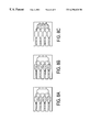
- FIGS. 2A-J illustrate a method of mixing two fluids together using a branching system of microchannels that join together.
- the channels include stopping means at points ‘a’ and ‘b’ to control the flow of fluid. Both fluids enter serially through a single common channel and are mixed subsequent to point ‘b’.
- FIGS. 2E-J illustrate the structure of the stopping means and the position of fluid at the stopping means whether the stopping means is a hydrophobic restriction, hydrophilic restriction, a hydrophobic patch or a salt patch.
- FIGS. 3A-G illustrate a method of splitting a fluid into a series of daughter channels.
- the filling of all sister wells or chambers prior to fluid flowing beyond the wells or chambers is controlled by stopping means at the far end of each well or chamber.
- FIGS. 3E-G illustrate different configuration of the stopping means, depending on which type is being employed.
- FIGS. 4A-G illustrate the presence of air or a gas which can be trapped in a series of hydrophobic microchannels and the use of a vent to allow the air or gas to escape while preventing fluid through the vent.
- FIGS. 4E-G illustrate alternative stopping means that allow air to escape if the fluid channels are not hydrophobic.
- FIGS. 5A-D illustrate a two-fluid, narrow-channel method of consolidating fluid from multiple chambers into one chamber.
- FIG. 6 illustrates a two-fluid, narrow-channel method of consolidating fluid from multiple chambers into one chamber wherein multiple narrow connecting channels connect the stopping means of each of the multiple chambers to the consolidation chamber.
- FIGS. 7A-D illustrate the concept of using air escape vents in conjunction with each of two channels wherein each of the channels comprises a stopping means.
- FIGS. 8A-C illustrate the use of ports to allow the introduction of air, another gas, or a second fluid to be introduced to force fluids past a stopping means.
- FIGS. 9A-D illustrate a physical displacement method in which pressure is applied to a flexible region of a circuit thereby forcing the fluid in the circuit to be moved.
- FIGS. 10A-C illustrate three versions of a consolidation circuit.
- FIGS. 11A-E illustrate the combination of stopping means and air escape vents to allow fluid to bypass a particular fluid circuit section.
- the bypassed region can be later perfused by a downstream stopping means generating enough backpressure to overcome the original stopping means that prevented flow into the non-perfused region.
- the invention is a method of using passive stopping means in microchannels to control the flow of fluids through the microchannels.
- a microchannel is defined herein to be a channel having a diameter of from 0.1 to 1000 microns. Advantage is taken of the surface effects between a fluid and the walls of the container holding the fluid. These surface effects come into play at the micro scale.
- the stopping means are designed to impede the flow of fluids under certain conditions thereby allowing control of the fluid. These stopping means act as passive valves because they regulate fluid flow but do not move.
- capillarity An example of the effect of surface forces is capillarity.
- Capillarity or capillary action, is demonstrated when water is drawn up into an open glass capillary tube without any outside pressure being applied. This is caused by the surface tension forces between the water and the glass surface, which pulls water into the capillary tube. The narrower the capillary tube the greater the effect of the force that pulls the water into the tube.
- One physical parameter that characterizes the magnitude of the capillary force is the contact angle between the water and the glass. For contact angles less than 90°, the material, e.g., glass, is considered to be hydrophilic and water is drawn up into the tube. When the material has a contact angle greater than 90° it is considered to be hydrophobic.
- a stopping means is generated by altering the character of a microchannel in such a way as to generate a pressure barrier.
- a pressure barrier is made by creating an abrupt change in the capillary force a fluid experiences while flowing through a microchannel.
- An abrupt change in capillary force can be made by changing the diameter of the microchannel the fluid is flowing through, by changing the contact angle of the microchannel material, by changing the surface tension of the flowing fluid, or by a combination of these methods.
- a pressure barrier can be generated by decreasing the diameter of the flow channel.
- This restriction (a narrowing) should be sufficient to cause fluid to flow in alternate channels having a diameter greater than the restriction means.
- a narrowing of a channel can be effected by different means. For example, a channel of otherwise constant diameter can have a bump or ridge at one or more points that cause a narrowing just at those points.
- Another alternative is a channel of one diameter narrowing suddenly to a channel of a smaller diameter, i.e., a wide channel narrowing to a less wide channel.
- the magnitude of the pressure barrier that is generated is proportional to the narrowness of the restriction compared to the narrowness of the channel prior to the restriction.
- a short restriction will have minimal effect on fluid flow once flow is established through the restriction. It is preferred that the restriction be 1-1000 ⁇ m long, more preferably 5-500 ⁇ m long, and most preferably 10-300 ⁇ m long.
- a pressure barrier can be generated by a channel restriction, similar to the method described for a hydrophobic material.
- the fluid will not want to exit a restriction, due to the capillary forces that are holding it there.
- the magnitude of the pressure barrier that is generated is proportional to the narrowness of the restriction compared to the narrowness of the channel after the restriction.
- a short restriction will have minimal effect on fluid flow once flow is established through the restriction.
- a pressure barrier can be generated by changing the contact angle of the flow channel. Microfabrication techniques, for example allow for the precise application of thin films of various materials that have a wide range of contact angles. The magnitude of the pressure barrier that is generated is proportional to the difference in the cosines of the contact angles of the materials comprising the stopping means.
- a stopping means can also be generated by changing the surface tension of the fluid within the microchannel. This, also, could be realized by utilizing microfabrication techniques to deposit thin films of various salts or surfactants that are absorbed into the fluid. The magnitude of the pressure barrier that is generated is proportional to the difference in the surface tensions of the fluid on each side of the stopping means.
- a stopping means in one of the channels may encourage the fluid to flow in the channel with no stopping means.
- the stopping means if designed properly, should have negligible effect on the established flow within the channels. In this case the stopping means acts as a passive valve.
- micro channels can be incorporated into a variety of techniques, e.g., splitting a sample into multiple chambers or samples or combining or mixing multiple samples together. Many variations of micro channel configurations can be designed for a particular need. The following examples illustrate some of the designs that arc quite useful.
- FIGS. 2A-J illustrate the use of stopping means in microchannels to regulate the flow of fluid through the channels.
- fluid in the main channel encounters stopping means ‘a’, causing the flow to be diverted into channel 2 .
- the fluid in channel 2 encounters stopping means ‘b’ which has a greater pressure barrier than stopping means ‘a’.
- FIG. 2C illustrates the fluid in channel 1 at the timepoint at which it reaches stopping means ‘b’. This causes the wetting of all surfaces on all sides of stopping means ‘b’.
- FIG. 2D shows a method by which two fluids can be mixed after insertion into a set of microchannels via a single microchannel.
- the example shows a first fluid inserted first into a main channel. A precisely measured amount of this first fluid can be inserted into the main channel.
- a second fluid is inserted into the main channel behind the first fluid. This second fluid forces the first fluid along the main channel until stopping means ‘a’ is reached. The first fluid is forced by this stopping means into channel 2 .
- stopping means ‘b’ Once channel 2 is filled and the first fluid reaches stopping means ‘b’, flow through channel 2 is stopped because stopping means ‘b’ has a greater pressure barrier than stopping means ‘a’. The force of the fluid in the main channel then forces the second fluid (all of the first fluid in this example having entered channel 2 ) past stopping means ‘a’. When the second fluid reaches the point of stopping means ‘b’ the pressure barrier of stopping means ‘b’ is overcome due to the wetting of both sides of stopping means ‘b’ and the removal of the meniscus which had originally formed at this point. At this point fluid will flow through channels 1 and 2 according to their respective impedances, and the first fluid that was in channel 2 will mix with the second fluid which was in channel 1 , this mixing, occurring in channel 1 subsequent to stopping means ‘b’.
- FIG. 2E illustrates the geometry and position of the stopped fluid if stopping means “a” were that of a hydrophobic restriction.
- FIG. 2F illustrates the geometry and position of the stopped fluid if stopping means “b” were that of a hydrophobic restriction.
- FIG. 2G illustrates the geometry and position of the stopped fluid if stopping means “a” were that of a hydrophilic restriction.
- FIG. 2H illustrates the geometry and position of the stopped fluid if stopping means “b” were that of a hydrophilic restriction.
- FIG. 2I illustrates the geometry and position of the stopped fluid if stopping means “a” were that of a hydrophobic patch or a film of salt.
- FIG. 2J illustrates the geometry and position of the stopped fluid if stopping means “b” were that of a hydrophobic patch of greater contact angle than that of “a”, or a film of salt that generates a greater surface tension in the fluid than that of “a”.
- the example of mixing fluids as illustrated by FIGS. 2A-J is a very simple model. More complex models in which more channels are involved could be utilized to mix more than two fluids together or to mix two fluids at one timepoint and other fluids at later timepoints, e.g. by having further branches similar to channel 2 farther downstream.
- the fluids which are inserted into the main channel can be inserted by several means.
- the main channel can encompass a single port into which all fluids are inserted or it can encompass multiple ports through which fluids can be inserted.
- the volume of fluids inserted can be matched with the volumes of channels to yield precise filling of channels and proper mixing of the fluids.
- Another example of utilizing passive valves is in a network of parallel daughter channels that flow through a set of parallel wells or chambers.
- the goal in this case is for a fluid or sample to be evenly distributed across all channels, and for all of the wells or chambers to fill simultaneously, and for the fluid in the wells or chambers to stop in the wells or chambers and not to continue flowing into the well or chamber outlet channel until desired.
- Once it is desired for the fluid to continue flowing it is desired that the fluid flow equally further down the fluid circuit, and equally into another set of chambers or wells, if present. This is performed automatically due to passive fluid dynamics. As fluid in the main channel flows toward the parallel daughter channels and wells or chambers, imperfections in the channel walls may encourage increased flow in one channel over another.
- the channel with increased flow will reach the well or chamber and fill up before its sister wells or chambers are filled.
- stopping means located at strategic points in the branching daughter channels will allow fluid to fill the branching channels and catch up and stop at each generation of stopping means before proceeding further down the fluid circuit.
- Each generation of stopping means will need to have a greater pressure barrier than the previous generation, in order to ensure the fluid does not pass one stopping means in one branch without first catching up to that generation of stopping means in all branches.
- the wells or chambers are designed with stopping means at their outlets.
- the stopping means acts as a passive valve and allows for an even division of fluid from a single channel into several daughter channels. It also allows for a specific sample in a main channel to be evenly distributed across a network of channels.
- the relative structures of the stopping means will depend on the materials, the fluid, and the pressure that is required to push the fluid past any imperfections and into all the channels, wells or chambers.
- FIGS. 3A-G illustrate the effect of imperfections in microchannels and the use of stopping means to overcome problems that could have been caused by the imperfections. It also illustrates how a sample in a main channel can be evenly distributed across multiple daughter channels.
- fluid in one branch encounters less friction and travels further than fluid in another branch, but is stopped at the first generation of stopping means.
- FIG. 3B illustrates the distribution of fluid and sample as the fluid in one set of branches reach the second generation of stopping means.
- FIG. 3C shows that the stopping means at the outlet of the wells or chambers allow all chambers to be filled, as the back pressure generated by these stopping means causes the fluid in all the branches to push past any previous stopping means and fill the chambers equally.
- FIG. 3D shows that once all wells or chambers are filled, and the desired processing in the wells or chambers is completed, fluid can be pushed out of wells or chambers, through the outlet channels, and further down the fluid circuit until the next generation of stopping means are encountered.
- the dark fluid is a sample and the lighter fluid is the system fluid. Ticks at the bottom of each figure represents the positions of the various generations of stopping means.
- FIG. 3E illustrates the geometry and position of the stopped fluid if the stopping means were that of a hydrophobic restriction.
- FIG. 3F illustrates the geometry and position of the stopped fluid if the stopping means were that of a hydrophilic restriction.
- FIG. 3G illustrates the geometry and position of the stopped fluid if the stopping means were that of a hydrophobic patch or a film of salt.
- FIGS. 3A-G need not be limited to 8 wells or chambers, rather many more wells or chambers could be present. Furthermore, there is no need for the wells or chambers to all be of the same size. This makes the division of a single sample injected at point ‘a’ into many separate wells or chambers a very simple matter. Many reaction wells or chambers can be filled without the need for pipetting individually into each well or chamber. Rather the sample is simply inserted into the apparatus at point ‘a’ and the microchannels and physical forces involved result in the filling of all wells or chambers.
- a stopping means is that of an air escape duct.
- a hydrophobic material utilizing a narrow channel as a stopping means it takes a considerable amount of pressure to force fluid into an extremely small channel or duct (on the order of a few microns in diameter). Because of this water will easily flow by such a duct and continue down the channel it is in and not enter the duct. Air, on the other hand, will have no difficulty moving through the duct if its path in the fluid is restricted. This fact allows a method of releasing air bubbles that might be trapped within a fluid channel.
- a similar air escape duct can be fabricated in hydrophilic materials using a restriction and then a widening of the channel, or by utilizing a hydrophobic or salt patch.
- FIG. 4A shows fluid traveling down two channels that join together.
- FIG. 4B shows the fluid in the lower channel reaching the intersection before the fluid in the upper channel. In such an event an air bubble will trap the fluid in the upper channel and prevent the fluid in that channel from traveling further.
- FIG. 4C illustrates how this can be overcome by the addition of an air escape duct. In this case, fluid in the upper channel can continue to flow as the air bubble travels out of the channel into the air duct.
- the air duct is represented by a long narrow channel, as might be indicative of a stopping means in a hydrophobic material.
- FIG. 4D illustrates fluid in both channels combining into the single channel and continuing to travel down the fluid circuit.
- FIG. 4E illustrates the geometry and position of the stopped fluid if the stopping means were that of a hydrophobic restriction, rather than a hydrophobic long narrow channel.
- FIG. 4F illustrates the geometry and position of the stopped fluid if the stopping means were that of a hydrophilic restriction.
- FIG. 4G illustrates the geometry and position of the stopped fluid if the stopping means were that of a hydrophobic patch or a film of salt.
- FIGS. 5A-D Another application of an air escape duct is to allow air to escape a fluidic circuit as fluid fills the circuit. This is usually done by having air escape ducts at the endpoint in a fluid circuit, which would allow air to escape the enclosed system.
- This utilization of air escape ducts are depicted in FIGS. 5A-D, FIG. 6, FIGS. 8A-C, and FIGS. 10A-C which are described in greater detail in the following Examples.
- Consolidation is the case where the contents of two or more channels or wells are to be combined into a fewer number of channels or wells.
- An example would be when 4 separate nucleic acid sequencing reactions are performed and then it is desired to combine the 4 reactions into a single well to be run on a gel or other analytical device. Four somewhat different consolidation methods are set out in this example.
- This method uses two fluids with a more viscous fluid being used to force a less viscous fluid through microchannels into a chamber or well to combine the less viscous fluid from multiple chambers or wells into a fewer number of chambers or wells. This method is illustrated by FIGS. 5A-D.
- the channel or wells to be joined are filled with a fluid.
- the outlet of the wells or channels contain stopping means used to contain the fluid at that point in the fluid circuit.
- the first fluid is stopped at the stopping means (FIG. 5 A).
- the stopping means it does not stop because the fluid meniscus is gone.
- FIGS. 3E-G illustrate the possible geometries and positions of the stopped fluid if the stopping means at the outlet of the channels or wells were that of a hydrophobic restriction, a hydrophilic restriction, or a hydrophobic patch or salt film, respectively. If the material were hydrophobic, only a long narrow channel would be needed, rather than both a restriction and then a long narrow channel.
- the utilization of air escape ducts at the consolidation chamber would be similar to those depicted in Example 3 and FIGS. 4E-G.
- FIG. 7A shows two fluids each entering a channel. Each channel has a stopping means at the point where the two channels on the left join to become a single channel. This allows the fluid in both channels to catch up to themselves at the point where the channels join (FIG. 7 C).
- the presence of an air vent in each of the two initial channels ensures that neither channel will have an air lock and both will advance to the joining region.
- FIG. 8A stopping means exist at the right of each of the 4 initial wells between each well and the exiting microchannel. Air or another gas is pushed through the ports (appearing as holes to the left of the 4 initial wells in FIGS. 8A-C) into the fluid channels. The air will displace the fluid downstream past the stopping means (FIG. 8 B), and in this case, into the consolidation well (FIG. 8 C). Air escape ducts in the consolidation well allow displaced air to exit the system so fluid can fill the consolidation well. A second fluid, rather than air, could also be pushed through the ports and used to displace the well volumes into the consolidation chamber.
- This method also requires the use of a third dimension.
- a portion, preferably the top or bottom, of the fluid circuit is made to be flexible at the point where physical displacement is to occur.
- the top or bottom plate has an opening that can allow a displacement means to compress the flexible fluid circuit to push fluid further downstream.
- This displacement means can be a fluid such as water, a gas such as air, or a plunger of some kind.
- FIGS. 9A-D shows an empty circuit.
- FIG. 9B shows the circuit partially filled with fluid.
- the bottom of the wells is made of a flexible material.
- a displacement means water
- the water compresses the bottom of the well (FIG. 9C) forcing the fluid from the well into the neighboring empty well (FIG. 9 D).
- the displacement means can be introduced elsewhere and need not be directly at the last filled well.
- FIGS. 10B-C Two modifications are illustrated in FIGS. 10B-C with FIG. 10A showing the original design for comparison.
- the design shown in FIG. 10B incorporates stopping means just upstream of each of the four wells. These stopping means facilitate an even distribution of a sample into each of the channel branches leading to the four wells.
- the 4 channels leading to the wells could have branched off from a single source or alternatively could have come from 4 different sources.
- FIG. 10B In practice the design of FIG. 10B does not work very well. This is because hydrophobic or hydrophilic restrictions act as jet nozzles pushing the second, more viscous fluid into the first fluid and causing unwanted mixing. This results in consolidation that is less than optimum and a fair amount of the second solution is found in the large consolidation well at the right in FIG. 10 B. Although this is useful as a mixing method, it is not the desired result in this case.
- FIG. 10C illustrates a modification of the consolidation design that eliminates the unwanted mixing seen with the design shown in FIG. 10 B.
- the entrance channel is put on the side of the well and the well is shaped somewhat in the form of a bowling pin where one bulb or section is significantly larger than the other section and the channel joining the two is not necessarily narrow and sharp. This allows the velocity of the second fluid to slow down and stabilize in the small first section before it interacts with the bulk of the first fluid in the large second section. If the transition between the first and second sections is smooth and gradual the second fluid (if properly chosen) will remain intact with itself and there will be a clear division between the first and second fluids as the second fluid fills the well and forces the first fluid through the narrow channel into the consolidation well.
- Example 1 illustrated the use of stopping means to divert fluid from one path to a branching path of a microfluidic circuit.
- Example 3 illustrated the use of air escape ducts to allow what would normally be trapped air to escape a channel and allow fluid to flow through the channel and eventually combine with the fluid in a joining channel. Utilizing these techniques a fluid circuit section can be temporarily bypassed using stopping means that divert fluid into a different path. A downstream stopping means can be used to overcome the pressure barrier at the original stopping means, and then an air escape duct can be used to allow fluid to flow through the bypassed region and rejoin the fluid circuit from which it had been cut off.
- FIGS. 11A-E illustrate this technique.
- fluid flows down a main channel and encounters a stopping means “a” that diverts the flow into a side channel.
- a stopping means “a” that diverts the flow into a side channel.
- the side channel rejoins the main channel it is prevented from entering the bypassed region of the main channel because of a second stopping means “b” that diverts the fluid to flow further down the main channel.
- a An air escape duct located at the upstream side of stopping, means “b” allows fluid to flow through the main channel. When it reaches stopping means “b” the meniscus disappears and the pressure barrier at stopping means “b” is eliminated.
- FIG. 11B illustrates a similar situation, except where fluid in a main channel is prevented from entering a side channel due to stopping means at “a” and “b”.
- FIG. 11C illustrates a chamber or well in the fluid circuit that may be bypassed initially, or perfused initially, depending on the location of the stopping means and air escape ducts.
- FIG. 11D illustrates a chamber that is located at the point of joining of two channels, where one inlet to the chamber is a bypassed branch from the main channel.
- FIG. 11E illustrates a main channel that includes a chamber, and a series of secondary channels that contain chambers and that are bypassed, all of which contain stopping means to prevent their perfusion, and air escape ducts that allow their ultimate perfusion.
- the stopping means at the upstream positions of the secondary channels are designed such that their pressure barriers can be overcome in the sequence that is desired, in this illustration from the top to the bottom, for the fluid circuit to function properly.
- the air escape ducts can either sequentially lead to the secondary channels that are not yet perfused, or can lead to the outside via ducts traveling in a third dimension.
- the above examples demonstrate methods of diluting or mixing two fluids traveling beside one another in a single channel, methods of allowing branching channels to divide flowing fluid, methods of allowing air to escape out of a fluid circuit, methods of consolidating channels or samples, and methods of temporarily bypassing a fluid path, all using passive fluid dynamics based on pressure barriers created by manipulating fluid capillary forces.
Abstract
Description
| TABLE 1 |
| θc for Selected Materials |
| Material | θc | ||
| Glass | 0 | ||
| Acetal | 60 | ||
| Polystyrene | 84 | ||
| HDPE (high density polyethylene) | 87.1 | ||
| PVDF (polyvinylidene fluoride) | 94.8 | ||
| PTFE (polytetrafluoroethylene) | 104 | ||
| FEP (fluorinated ethylenepropylene) | 111 | ||
Claims (58)
Priority Applications (4)
| Application Number | Priority Date | Filing Date | Title |
|---|---|---|---|
| US09/417,691 US6296020B1 (en) | 1998-10-13 | 1999-10-13 | Fluid circuit components based upon passive fluid dynamics |
| US09/967,402 US6601613B2 (en) | 1998-10-13 | 2001-09-28 | Fluid circuit components based upon passive fluid dynamics |
| US10/060,442 US6591852B1 (en) | 1998-10-13 | 2002-01-30 | Fluid circuit components based upon passive fluid dynamics |
| US10/142,555 US6637463B1 (en) | 1998-10-13 | 2002-05-10 | Multi-channel microfluidic system design with balanced fluid flow distribution |
Applications Claiming Priority (3)
| Application Number | Priority Date | Filing Date | Title |
|---|---|---|---|
| US10397098P | 1998-10-13 | 1998-10-13 | |
| US13809299P | 1999-06-08 | 1999-06-08 | |
| US09/417,691 US6296020B1 (en) | 1998-10-13 | 1999-10-13 | Fluid circuit components based upon passive fluid dynamics |
Related Child Applications (1)
| Application Number | Title | Priority Date | Filing Date |
|---|---|---|---|
| US09/967,402 Continuation US6601613B2 (en) | 1998-10-13 | 2001-09-28 | Fluid circuit components based upon passive fluid dynamics |
Publications (1)
| Publication Number | Publication Date |
|---|---|
| US6296020B1 true US6296020B1 (en) | 2001-10-02 |
Family
ID=26801047
Family Applications (1)
| Application Number | Title | Priority Date | Filing Date |
|---|---|---|---|
| US09/417,691 Expired - Fee Related US6296020B1 (en) | 1998-10-13 | 1999-10-13 | Fluid circuit components based upon passive fluid dynamics |
Country Status (9)
| Country | Link |
|---|---|
| US (1) | US6296020B1 (en) |
| EP (1) | EP1125129A1 (en) |
| JP (1) | JP2002527250A (en) |
| KR (1) | KR20010089295A (en) |
| CN (1) | CN1326549A (en) |
| AU (1) | AU763497B2 (en) |
| BR (1) | BR9914554A (en) |
| CA (1) | CA2347182C (en) |
| WO (1) | WO2000022436A1 (en) |
Cited By (240)
| Publication number | Priority date | Publication date | Assignee | Title |
|---|---|---|---|---|
| US20010035350A1 (en) * | 2000-03-28 | 2001-11-01 | Minoru Seki | Microchip for aqueous distribution and method of aqueous distribution using the same |
| US20020012616A1 (en) * | 2000-07-03 | 2002-01-31 | Xiaochuan Zhou | Fluidic methods and devices for parallel chemical reactions |
| WO2002012734A1 (en) * | 2000-08-04 | 2002-02-14 | Biomicro Systems, Inc. | Remote valving for microfluidic flow control |
| US6418968B1 (en) | 2001-04-20 | 2002-07-16 | Nanostream, Inc. | Porous microfluidic valves |
| US20020097633A1 (en) * | 2000-08-07 | 2002-07-25 | Nanostream,Inc. | Multi-stream microfluidic mixers |
| US6451264B1 (en) * | 2000-01-28 | 2002-09-17 | Roche Diagnostics Corporation | Fluid flow control in curved capillary channels |
| US20020187074A1 (en) * | 2001-06-07 | 2002-12-12 | Nanostream, Inc. | Microfluidic analytical devices and methods |
| US20020197733A1 (en) * | 2001-06-20 | 2002-12-26 | Coventor, Inc. | Microfluidic system including a virtual wall fluid interface port for interfacing fluids with the microfluidic system |
| US20020195463A1 (en) * | 2001-05-31 | 2002-12-26 | Minoru Seki | Control mechanism for trace quantity of liquid |
| US20020195343A1 (en) * | 2001-06-20 | 2002-12-26 | Coventor, Inc. | Microfabricated separation device employing a virtual wall for interfacing fluids |
| US20030015244A1 (en) * | 2001-04-25 | 2003-01-23 | Ismagilov Rustem F. | Fluidic switches and method for controlling flow in fluidic systems |
| US20030015425A1 (en) * | 2001-06-20 | 2003-01-23 | Coventor Inc. | Microfluidic system including a virtual wall fluid interface port for interfacing fluids with the microfluidic system |
| US20030077204A1 (en) * | 2001-10-18 | 2003-04-24 | Minoru Seki | Micro-globule metering and sampling structure and microchips having the structure |
| US20030099577A1 (en) * | 2000-04-03 | 2003-05-29 | Philippe Renaud | Device for dispensing accurately-controlled small doses of liquid |
| US20030118486A1 (en) * | 2000-07-03 | 2003-06-26 | Xeotron Corporation | Fluidic methods and devices for parallel chemical reactions |
| US6591852B1 (en) | 1998-10-13 | 2003-07-15 | Biomicro Systems, Inc. | Fluid circuit components based upon passive fluid dynamics |
| US20030133358A1 (en) * | 2002-01-11 | 2003-07-17 | Nanostream, Inc. | Multi-stream microfluidic aperture mixers |
| US20030138819A1 (en) * | 2001-10-26 | 2003-07-24 | Haiqing Gong | Method for detecting disease |
| US6601613B2 (en) | 1998-10-13 | 2003-08-05 | Biomicro Systems, Inc. | Fluid circuit components based upon passive fluid dynamics |
| US20030159742A1 (en) * | 2002-02-23 | 2003-08-28 | Nanostream, Inc. | Microfluidic multi-splitter |
| US20030170881A1 (en) * | 2002-03-05 | 2003-09-11 | I-Stat Corporation | Apparatus and methods for analyte measurement and immuno assay |
| US20030173650A1 (en) * | 2000-05-12 | 2003-09-18 | Olle Larsson | Micro channel in a substrate |
| US20030185713A1 (en) * | 2002-03-29 | 2003-10-02 | Leslie Leonard | Capillary flow for a heterogenous assay in a micro-channel environment |
| US20030198130A1 (en) * | 2000-08-07 | 2003-10-23 | Nanostream, Inc. | Fluidic mixer in microfluidic system |
| US6637463B1 (en) * | 1998-10-13 | 2003-10-28 | Biomicro Systems, Inc. | Multi-channel microfluidic system design with balanced fluid flow distribution |
| US20030210607A1 (en) * | 2002-05-08 | 2003-11-13 | Coventor, Inc. | On chip dilution system |
| US20040018116A1 (en) * | 2002-07-26 | 2004-01-29 | Desmond Sean M. | Microfluidic size-exclusion devices, systems, and methods |
| US20040018117A1 (en) * | 2002-07-26 | 2004-01-29 | Desmond Sean M. | Micro-channel design features that facilitate centripetal fluid transfer |
| US20040027915A1 (en) * | 2000-08-25 | 2004-02-12 | Holger Lowe | Method and statistical micromixer for mixing at least two liquids |
| US20040035481A1 (en) * | 2002-08-23 | 2004-02-26 | Seoul National University | Micro channel unit |
| US20040042930A1 (en) * | 2002-08-30 | 2004-03-04 | Clemens Charles E. | Reaction chamber with capillary lock for fluid positioning and retention |
| US6705357B2 (en) * | 2000-09-18 | 2004-03-16 | President And Fellows Of Harvard College | Method and apparatus for gradient generation |
| US20040058408A1 (en) * | 1998-04-27 | 2004-03-25 | Gyros Ab | Microfabricated apparatus for cell based assays |
| US20040063217A1 (en) * | 2002-09-27 | 2004-04-01 | Webster James Russell | Miniaturized fluid delivery and analysis system |
| US6727451B1 (en) * | 1998-04-08 | 2004-04-27 | Evotec Technologies Gmbh | Method and device for manipulating microparticles in fluid flows |
| US6733730B1 (en) * | 1999-04-26 | 2004-05-11 | Sandia Corporation | Method and apparatus for reducing sample dispersion in turns and junctions of microchannel systems |
| US20040091398A1 (en) * | 2001-06-20 | 2004-05-13 | Teragenics, Inc. | Microfluidic system including a virtual wall fluid interface port for interfacing fluids with the microfluidic system |
| US20040091399A1 (en) * | 2002-11-11 | 2004-05-13 | Chung Kwang Hyo | Device for controlling fluid using surface tension |
| US20040099310A1 (en) * | 2001-01-05 | 2004-05-27 | Per Andersson | Microfluidic device |
| US6743399B1 (en) | 1999-10-08 | 2004-06-01 | Micronics, Inc. | Pumpless microfluidics |
| US20040120856A1 (en) * | 2001-03-19 | 2004-06-24 | Per Andersson | Structural units that define fluidic functions |
| US6755211B1 (en) * | 2000-04-14 | 2004-06-29 | Nanostream, Inc. | Microfluidic systems with inter-channel impedances |
| WO2004061414A2 (en) * | 2002-12-19 | 2004-07-22 | Bayer Healthcare Llc | Method and apparatus for splitting of specimens into multiple channels of a microfluidic device |
| DE10302720A1 (en) * | 2003-01-23 | 2004-08-05 | Steag Microparts Gmbh | Microfluidic switch for stopping the flow of fluid during a time interval |
| US20040202579A1 (en) * | 1998-05-08 | 2004-10-14 | Anders Larsson | Microfluidic device |
| US20040231736A1 (en) * | 2003-05-22 | 2004-11-25 | Kim Sung Jin | Micro fluidic device for controlling flow time of micro fluid |
| US20050032238A1 (en) * | 2003-08-07 | 2005-02-10 | Nanostream, Inc. | Vented microfluidic separation devices and methods |
| US20050042770A1 (en) * | 2003-05-23 | 2005-02-24 | Gyros Ab | Fluidic functions based on non-wettable surfaces |
| US20050042766A1 (en) * | 2002-06-07 | 2005-02-24 | Amic Ab | Micro fluidic structures |
| US20050045238A1 (en) * | 2003-08-29 | 2005-03-03 | Jing-Tang Yang | Micro valve device |
| KR100471377B1 (en) * | 2002-11-20 | 2005-03-11 | 한국전자통신연구원 | Microfluidic Devices Controlled by Surface Tension |
| US20050083781A1 (en) * | 2003-10-15 | 2005-04-21 | Caren Michael P. | Methods and apparatus for mixing of liquids |
| US20050113739A1 (en) * | 2003-11-21 | 2005-05-26 | Matthias Stiene | Device and method for extracting body fluid |
| EP1534429A2 (en) * | 2002-07-26 | 2005-06-01 | Applera Corporation | Micro-channel design features that facilitate centripetal fluid transfer |
| US20050153433A1 (en) * | 2001-08-28 | 2005-07-14 | Gyros Ab | Retaining microfluidic microcavity and other microfluidic structures |
| US20050196872A1 (en) * | 2004-03-05 | 2005-09-08 | Hoa Nguyen | Mechanical device for mixing a fluid sample with a treatment solution |
| US20050220629A1 (en) * | 2004-03-31 | 2005-10-06 | Sebastian Bohm | Method of segregating a bolus of fluid using a pneumatic actuator in a fluid handling circuit |
| US20050217742A1 (en) * | 2004-03-31 | 2005-10-06 | Sebastian Bohm | Microfluidic circuit including an array of triggerable passive valves |
| US20050220644A1 (en) * | 2004-03-31 | 2005-10-06 | Sebastian Bohm | Pneumatic actuator for bolus generation in a fluid handling circuit |
| US20060002817A1 (en) * | 2004-06-30 | 2006-01-05 | Sebastian Bohm | Flow modulation devices |
| US20060000709A1 (en) * | 2004-06-30 | 2006-01-05 | Sebastian Bohm | Methods for modulation of flow in a flow pathway |
| US20060006065A1 (en) * | 2004-06-05 | 2006-01-12 | Symyx Technologies, Inc. | Microfluidic fluid distribution manifold for use with multi-channel reactor systems |
| US20060039829A1 (en) * | 2004-08-21 | 2006-02-23 | Ji Won Suk | Microfluidic device, and diagnostic and analytical apparatus using the same |
| US20060073074A1 (en) * | 2004-10-06 | 2006-04-06 | Lars Winther | Enhanced sample processing system and methods of biological slide processing |
| US20060088451A1 (en) * | 2004-10-26 | 2006-04-27 | Akihisa Nakajima | Micro-reactor for biological substance inspection and biological substance inspection device |
| US20060115382A1 (en) * | 2004-11-29 | 2006-06-01 | Canon Kabushiki Kaisha | Fluid-conveying apparatus and method for conveying fluid by using the same |
| KR100591244B1 (en) | 2004-12-14 | 2006-06-20 | 한국전자통신연구원 | Microfluidic device capable of controlling the pressure of the inlet and microfluidic network having the same |
| WO2006069757A1 (en) * | 2004-12-23 | 2006-07-06 | Perdita Backes | Novel microfluidic sample holder |
| US20060159592A1 (en) * | 1998-05-08 | 2006-07-20 | Gyros Patent Ab | Microfluidic device |
| WO2006098696A1 (en) * | 2005-03-16 | 2006-09-21 | Attogenix Biosystems Pte Ltd. | Methods and device for transmitting, enclosing and analysing fluid samples |
| US20060253692A1 (en) * | 2005-05-09 | 2006-11-09 | Searete Llc, A Limited Liability Corporation Of The State Of Delaware | Limited use memory device with associated information |
| WO2005108991A3 (en) * | 2004-05-04 | 2006-11-23 | Metrika Inc | Mechanical cartridge with test strip fluid control features for use in a fluid analyte meter |
| US20060263264A1 (en) * | 2001-06-20 | 2006-11-23 | Cytonome, Inc | Microfluidic system including a virtual wall fluid interface port for interfacing fluids with the microfluidic system |
| US20060263914A1 (en) * | 2005-05-19 | 2006-11-23 | Konica Minolta Medical & Graphic, Inc. | Testing chip and micro integrated analysis system |
| US20060268661A1 (en) * | 2005-05-09 | 2006-11-30 | Searete Llc, A Limited Liability Corporation Of The State Of Delaware | Fluid mediated disk activation and deactivation mechanisms |
| US20060275852A1 (en) * | 2005-06-06 | 2006-12-07 | Montagu Jean I | Assays based on liquid flow over arrays |
| US20060275179A1 (en) * | 2003-05-21 | 2006-12-07 | Centre National De La Recherche Scientifique | Microfluidic device |
| US20060278287A1 (en) * | 2003-05-23 | 2006-12-14 | Matthew Fielden | Hydrophilic/hydrophobic surfaces |
| US20060280029A1 (en) * | 2005-06-13 | 2006-12-14 | President And Fellows Of Harvard College | Microfluidic mixer |
| US20060291354A1 (en) * | 2005-05-09 | 2006-12-28 | Searete Llc, A Limited Liability Corporation Of The State Of Delaware | Method and system for fluid mediated disk activation and deactivation |
| US20070002708A1 (en) * | 2005-05-09 | 2007-01-04 | Searete, Llc, A Limited Liability Corporation Of The State Of Delaware | Rotation responsive disk activation and deactivation mechanisms |
| US20070058505A1 (en) * | 2005-09-09 | 2007-03-15 | Searete Llc, A Limited Liability Corporation Of The State Of Delaware | Data retrieval systems |
| US20070070868A1 (en) * | 2005-05-09 | 2007-03-29 | Searete Llc, A Limited Liability Corporation Of The State Of Delaware | Fluid mediated disk activation and deactivation mechanisms |
| US20070080976A1 (en) * | 2005-10-11 | 2007-04-12 | Shaw-Hwa Parng | Biochip with microchannels |
| US20070105236A1 (en) * | 2003-11-29 | 2007-05-10 | Digital Bio Technology | Method of examining blood type and apparatus for examining blood type using the method |
| US20070173759A1 (en) * | 1999-10-08 | 2007-07-26 | Augustine Scott D | Intravenous fluid warming cassette with stiffening member and integral handle |
| US20070253316A1 (en) * | 2005-05-09 | 2007-11-01 | Searete Llc, A Limited Liability Corporation Of The State Of Delaware | Method of manufacturing a limited use data storing device |
| US20070263477A1 (en) * | 2006-05-11 | 2007-11-15 | The Texas A&M University System | Method for mixing fluids in microfluidic channels |
| US20080006533A1 (en) * | 2001-11-13 | 2008-01-10 | Caliper Technologies Corp. | Prevention of Precipitate Blockage in Microfluidic Channels |
| US20080031089A1 (en) * | 2006-08-04 | 2008-02-07 | Zhenghua Ji | Low-volume mixing of sample |
| US20080032311A1 (en) * | 2006-08-04 | 2008-02-07 | Zhenghua Ji | Low volume mixing of sample |
| US20080038839A1 (en) * | 2004-01-26 | 2008-02-14 | Vincent Linder | Fluid Delivery System And Method |
| US7338760B2 (en) | 2001-10-26 | 2008-03-04 | Ntu Ventures Private Limited | Sample preparation integrated chip |
| US20080069729A1 (en) * | 2005-02-16 | 2008-03-20 | Mcneely Michael R | Liquid Valving Using Reactive or Responsive Materials |
| US7347617B2 (en) * | 2003-08-19 | 2008-03-25 | Siemens Healthcare Diagnostics Inc. | Mixing in microfluidic devices |
| US20080081378A1 (en) * | 2006-07-12 | 2008-04-03 | Metrika, Inc. | Mechanical device for mixing a fluid sample with a treatment solution |
| EP1942347A1 (en) * | 2005-10-28 | 2008-07-09 | Arkray, Inc. | Liquid feeding method and cartridge to be used therein |
| US7412990B2 (en) | 2003-12-22 | 2008-08-19 | Electronics And Telecommunications Research Institute | Microfluidic control device and method for controlling microfluid |
| EP1983060A1 (en) * | 2007-04-17 | 2008-10-22 | Tesa AG | Biosensor and production of same |
| WO2008127191A1 (en) * | 2007-04-16 | 2008-10-23 | Åmic AB | Device for handling liquid samples |
| US20080269676A1 (en) * | 2007-04-24 | 2008-10-30 | Arizant Healthcare Inc. | High flow rate infusion with extraction assist |
| US20080273918A1 (en) * | 2007-05-04 | 2008-11-06 | Claros Diagnostics, Inc. | Fluidic connectors and microfluidic systems |
| US7459127B2 (en) * | 2002-02-26 | 2008-12-02 | Siemens Healthcare Diagnostics Inc. | Method and apparatus for precise transfer and manipulation of fluids by centrifugal and/or capillary forces |
| US20080314454A1 (en) * | 2006-02-16 | 2008-12-25 | Commissariat A L'energie Atomique | Method for Controlling the Progression of a Fluid In a Microfluidic Component |
| US20090044603A1 (en) * | 2007-08-14 | 2009-02-19 | General Electric Company | Article, device, and method |
| US20090165873A1 (en) * | 2007-12-28 | 2009-07-02 | Lalit Chordia | Variable ratio flow splitter for a flowstream |
| DE202009008052U1 (en) | 2009-03-23 | 2009-08-27 | Thinxxs Microtechnology Ag | Device for transporting a fluid in a channel strand of a microfluidic element |
| US20090250347A1 (en) * | 2008-04-03 | 2009-10-08 | Protea Biosciences, Inc. | Microfluidic devices & processes for electrokinetic transport |
| US20090250345A1 (en) * | 2008-04-03 | 2009-10-08 | Protea Biosciences, Inc. | Microfluidic electroelution devices & processes |
| US20090266421A1 (en) * | 2008-04-25 | 2009-10-29 | Claros Diagnostics, Inc. | Flow control in microfluidic systems |
| US7668068B2 (en) | 2005-06-09 | 2010-02-23 | Searete Llc | Rotation responsive disk activation and deactivation mechanisms |
| US20100078086A1 (en) * | 2008-09-29 | 2010-04-01 | Roland Guidat | Multiple flow path microreactor design |
| US20100167943A1 (en) * | 2008-06-09 | 2010-07-01 | Nils Adey | System and Method for Hybridization Slide Processing |
| US7770028B2 (en) | 2005-09-09 | 2010-08-03 | Invention Science Fund 1, Llc | Limited use data storing device |
| US20100196207A1 (en) * | 2009-02-02 | 2010-08-05 | David Steinmiller | Structures for controlling light interaction with microfluidic devices |
| US20100200021A1 (en) * | 2006-02-17 | 2010-08-12 | Nils Adey | Slide Conditioning Systems and Methods |
| US20110003398A1 (en) * | 2009-07-02 | 2011-01-06 | Amic Ab | Assay device comprising serial reaction zones |
| US20110002207A1 (en) * | 2006-06-19 | 2011-01-06 | Searete Llc, A Limited Liability Corporation Of The State Of Delaware | Method and system for fluid mediated disk activation and deactivation |
| US7907486B2 (en) | 2006-06-20 | 2011-03-15 | The Invention Science Fund I, Llc | Rotation responsive disk activation and deactivation mechanisms |
| US7916592B2 (en) | 2005-05-09 | 2011-03-29 | The Invention Science Fund I, Llc | Fluid mediated disk activation and deactivation mechanisms |
| US7916615B2 (en) | 2005-06-09 | 2011-03-29 | The Invention Science Fund I, Llc | Method and system for rotational control of data storage devices |
| US20110124025A1 (en) * | 2009-11-20 | 2011-05-26 | College Of Nanoscale Science And Engineering | Cell Collecting Devices and Methods for Collecting Cells |
| US20110120562A1 (en) * | 2009-11-24 | 2011-05-26 | Claros Diagnostics, Inc. | Fluid mixing and delivery in microfluidic systems |
| US20110177586A1 (en) * | 2002-05-09 | 2011-07-21 | The University Of Chicago | Device and method for pressure-driven plug transport |
| US20110181981A1 (en) * | 2005-05-09 | 2011-07-28 | Searete Llc, A Limited Liability Corporation Of The State Of Delaware | Method and system for rotational control of data storage devices |
| US20110190153A1 (en) * | 2008-06-09 | 2011-08-04 | Nils Adey | System and method for hybridization slide processing |
| US20110192217A1 (en) * | 2010-02-08 | 2011-08-11 | Agilent Technologies, Inc. | Flow Distribution Mixer |
| USD645971S1 (en) | 2010-05-11 | 2011-09-27 | Claros Diagnostics, Inc. | Sample cassette |
| DE102010028012A1 (en) * | 2010-04-21 | 2011-10-27 | Qiagen Gmbh | Liquid control for micro flow system |
| US20110269226A1 (en) * | 2008-08-27 | 2011-11-03 | Agency For Science, Technology And Research | Microfluidic Continuous Flow Device for Culturing Biological Material |
| US20120003675A1 (en) * | 2010-03-17 | 2012-01-05 | Retterer Scott T | Method for Preparing Small Volume Reaction Containers |
| US8099608B2 (en) | 2005-05-09 | 2012-01-17 | The Invention Science Fund I, Llc | Limited use data storing device |
| US8101431B2 (en) | 2004-02-27 | 2012-01-24 | Board Of Regents, The University Of Texas System | Integration of fluids and reagents into self-contained cartridges containing sensor elements and reagent delivery systems |
| US8105849B2 (en) | 2004-02-27 | 2012-01-31 | Board Of Regents, The University Of Texas System | Integration of fluids and reagents into self-contained cartridges containing sensor elements |
| US8121016B2 (en) | 2005-05-09 | 2012-02-21 | The Invention Science Fund I, Llc | Rotation responsive disk activation and deactivation mechanisms |
| WO2012027527A2 (en) * | 2010-08-26 | 2012-03-01 | Reichert David E | Microreactor and method for preparing a radiolabeled complex or a biomolecule conjugate |
| US8140745B2 (en) | 2005-09-09 | 2012-03-20 | The Invention Science Fund I, Llc | Data retrieval methods |
| US8159925B2 (en) | 2005-08-05 | 2012-04-17 | The Invention Science Fund I, Llc | Limited use memory device with associated information |
| US20120097272A1 (en) * | 2009-01-30 | 2012-04-26 | Universiteit Leiden | Phaseguide patterns for liquid manipulation |
| US8220014B2 (en) | 2005-05-09 | 2012-07-10 | The Invention Science Fund I, Llc | Modifiable memory devices having limited expected lifetime |
| US8218262B2 (en) | 2005-05-09 | 2012-07-10 | The Invention Science Fund I, Llc | Method of manufacturing a limited use data storing device including structured data and primary and secondary read-support information |
| US8264928B2 (en) | 2006-06-19 | 2012-09-11 | The Invention Science Fund I, Llc | Method and system for fluid mediated disk activation and deactivation |
| US8312890B1 (en) * | 2004-10-18 | 2012-11-20 | Applied Biosystems, Llc | Dissolvable valve in a fluid processing device |
| US8377398B2 (en) | 2005-05-31 | 2013-02-19 | The Board Of Regents Of The University Of Texas System | Methods and compositions related to determination and use of white blood cell counts |
| US8389272B2 (en) | 2004-01-26 | 2013-03-05 | President And Fellows Of Harvard College | Fluid delivery system and method |
| US20130114369A1 (en) * | 2010-06-28 | 2013-05-09 | Dic Corporation | Micro mixer |
| US8462605B2 (en) | 2005-05-09 | 2013-06-11 | The Invention Science Fund I, Llc | Method of manufacturing a limited use data storing device |
| US20130206264A1 (en) * | 2010-03-15 | 2013-08-15 | Boehringer Ingelheim International Gmbh | Device and method for manipulating a liquid |
| US8580569B2 (en) | 2010-04-16 | 2013-11-12 | Opko Diagnostics, Llc | Feedback control in microfluidic systems |
| US8591829B2 (en) | 2008-12-18 | 2013-11-26 | Opko Diagnostics, Llc | Reagent storage in microfluidic systems and related articles and methods |
| US20140065597A1 (en) * | 2011-03-08 | 2014-03-06 | Universiteit Leiden | Apparatuses for and methods of processing cells and related structures |
| EP2805772A1 (en) * | 2004-09-02 | 2014-11-26 | Honeywell International Inc. | Method and apparatus for determining one or more operating parameters for a microfluidic circuit |
| WO2015047190A1 (en) * | 2013-09-30 | 2015-04-02 | Agency For Science, Technology And Research | Microfluidic device |
| US20150107709A1 (en) * | 2010-09-14 | 2015-04-23 | Xingyue Peng | Microdevice structure of microchannel chip |
| US9038919B2 (en) | 2003-04-10 | 2015-05-26 | President And Fellows Of Harvard College | Formation and control of fluidic species |
| US9068699B2 (en) | 2007-04-19 | 2015-06-30 | Brandeis University | Manipulation of fluids, fluid components and reactions in microfluidic systems |
| TWI494567B (en) * | 2011-10-13 | 2015-08-01 | Univ Nat Cheng Kung | Chip, device, and method for blood coagulation |
| US20150258545A1 (en) * | 2014-03-14 | 2015-09-17 | Agency For Science, Technology And Research | Microfluidic devices and methods for controlling a microfluidic device |
| US20150306597A1 (en) * | 2012-11-16 | 2015-10-29 | Lightstat, Llc | Redundant microfluidic measurement techniques |
| US9255866B2 (en) | 2013-03-13 | 2016-02-09 | Opko Diagnostics, Llc | Mixing of fluids in fluidic systems |
| US9328344B2 (en) | 2006-01-11 | 2016-05-03 | Raindance Technologies, Inc. | Microfluidic devices and methods of use in the formation and control of nanoreactors |
| US9366632B2 (en) | 2010-02-12 | 2016-06-14 | Raindance Technologies, Inc. | Digital analyte analysis |
| US9396752B2 (en) | 2005-08-05 | 2016-07-19 | Searete Llc | Memory device activation and deactivation |
| US9440232B2 (en) | 2007-02-06 | 2016-09-13 | Raindance Technologies, Inc. | Manipulation of fluids and reactions in microfluidic systems |
| US9562837B2 (en) | 2006-05-11 | 2017-02-07 | Raindance Technologies, Inc. | Systems for handling microfludic droplets |
| EP2972185A4 (en) * | 2013-03-14 | 2017-02-22 | The Board of Trustees of The Leland Stanford Junior University | Capillary barriers for staged loading of microfluidic devices |
| US9789482B2 (en) | 2003-08-27 | 2017-10-17 | President And Fellows Of Harvard College | Methods of introducing a fluid into droplets |
| USD804682S1 (en) | 2015-08-10 | 2017-12-05 | Opko Diagnostics, Llc | Multi-layered sample cassette |
| US9856530B2 (en) | 2012-12-14 | 2018-01-02 | 10X Genomics, Inc. | Methods and systems for processing polynucleotides |
| US9878323B2 (en) | 2005-12-21 | 2018-01-30 | Meso Scale Technologies, Llc | Assay modules having assay reagents and methods of making and using same |
| EP3154666A4 (en) * | 2014-06-13 | 2018-02-21 | Mcneely, Michael, Ryan | Capillary pressure re-set mechanism and applications |
| US9951386B2 (en) | 2014-06-26 | 2018-04-24 | 10X Genomics, Inc. | Methods and systems for processing polynucleotides |
| US9962693B2 (en) | 2012-12-13 | 2018-05-08 | Koninklijke Philips N.V. | Fluidic system with fluidic stop |
| US9975122B2 (en) | 2014-11-05 | 2018-05-22 | 10X Genomics, Inc. | Instrument systems for integrated sample processing |
| US10011872B1 (en) | 2016-12-22 | 2018-07-03 | 10X Genomics, Inc. | Methods and systems for processing polynucleotides |
| US10053723B2 (en) | 2012-08-14 | 2018-08-21 | 10X Genomics, Inc. | Capsule array devices and methods of use |
| US10071377B2 (en) | 2014-04-10 | 2018-09-11 | 10X Genomics, Inc. | Fluidic devices, systems, and methods for encapsulating and partitioning reagents, and applications of same |
| US20180311627A1 (en) * | 2015-06-29 | 2018-11-01 | Imec Vzw | Valve-Less Mixing Method and Mixing Device |
| US10150963B2 (en) | 2013-02-08 | 2018-12-11 | 10X Genomics, Inc. | Partitioning and processing of analytes and other species |
| US10221442B2 (en) | 2012-08-14 | 2019-03-05 | 10X Genomics, Inc. | Compositions and methods for sample processing |
| US10221436B2 (en) | 2015-01-12 | 2019-03-05 | 10X Genomics, Inc. | Processes and systems for preparation of nucleic acid sequencing libraries and libraries prepared using same |
| US10227648B2 (en) | 2012-12-14 | 2019-03-12 | 10X Genomics, Inc. | Methods and systems for processing polynucleotides |
| US10273541B2 (en) | 2012-08-14 | 2019-04-30 | 10X Genomics, Inc. | Methods and systems for processing polynucleotides |
| US10279345B2 (en) | 2014-12-12 | 2019-05-07 | Opko Diagnostics, Llc | Fluidic systems comprising an incubation channel, including fluidic systems formed by molding |
| US10287623B2 (en) | 2014-10-29 | 2019-05-14 | 10X Genomics, Inc. | Methods and compositions for targeted nucleic acid sequencing |
| US10323279B2 (en) | 2012-08-14 | 2019-06-18 | 10X Genomics, Inc. | Methods and systems for processing polynucleotides |
| US10351905B2 (en) | 2010-02-12 | 2019-07-16 | Bio-Rad Laboratories, Inc. | Digital analyte analysis |
| US10400235B2 (en) | 2017-05-26 | 2019-09-03 | 10X Genomics, Inc. | Single cell analysis of transposase accessible chromatin |
| US10400280B2 (en) | 2012-08-14 | 2019-09-03 | 10X Genomics, Inc. | Methods and systems for processing polynucleotides |
| US10415030B2 (en) | 2016-01-29 | 2019-09-17 | Purigen Biosystems, Inc. | Isotachophoresis for purification of nucleic acids |
| US10428326B2 (en) | 2017-01-30 | 2019-10-01 | 10X Genomics, Inc. | Methods and systems for droplet-based single cell barcoding |
| US10533221B2 (en) | 2012-12-14 | 2020-01-14 | 10X Genomics, Inc. | Methods and systems for processing polynucleotides |
| US10550429B2 (en) | 2016-12-22 | 2020-02-04 | 10X Genomics, Inc. | Methods and systems for processing polynucleotides |
| US10620194B2 (en) | 2001-03-19 | 2020-04-14 | Gyros Patent Ab | Characterization of reaction variables |
| CN111032202A (en) * | 2017-09-06 | 2020-04-17 | 沃特世科技公司 | Fluid mixer |
| US10639597B2 (en) | 2006-05-11 | 2020-05-05 | Bio-Rad Laboratories, Inc. | Microfluidic devices |
| US10647981B1 (en) | 2015-09-08 | 2020-05-12 | Bio-Rad Laboratories, Inc. | Nucleic acid library generation methods and compositions |
| US10672503B2 (en) | 2012-03-05 | 2020-06-02 | Opko Diagnostics, Llc | Methods and apparatuses for conducting analyses |
| US10677791B2 (en) | 2014-07-01 | 2020-06-09 | Nikon Corporation | Fluidic device, fluid control method, testing device, testing method, and fluidic device manufacturing method |
| US10697000B2 (en) | 2015-02-24 | 2020-06-30 | 10X Genomics, Inc. | Partition processing methods and systems |
| US10732649B2 (en) | 2004-07-02 | 2020-08-04 | The University Of Chicago | Microfluidic system |
| US10745742B2 (en) | 2017-11-15 | 2020-08-18 | 10X Genomics, Inc. | Functionalized gel beads |
| US10752949B2 (en) | 2012-08-14 | 2020-08-25 | 10X Genomics, Inc. | Methods and systems for processing polynucleotides |
| US10774370B2 (en) | 2015-12-04 | 2020-09-15 | 10X Genomics, Inc. | Methods and compositions for nucleic acid analysis |
| US10815525B2 (en) | 2016-12-22 | 2020-10-27 | 10X Genomics, Inc. | Methods and systems for processing polynucleotides |
| US10829815B2 (en) | 2017-11-17 | 2020-11-10 | 10X Genomics, Inc. | Methods and systems for associating physical and genetic properties of biological particles |
| US10852310B2 (en) | 2015-12-11 | 2020-12-01 | Opko Diagnostics, Llc | Fluidic systems involving incubation of samples and/or reagents |
| US20200400691A1 (en) * | 2013-05-23 | 2020-12-24 | Qorvo Biotechnologies, Llc | Two part assembly |
| WO2021014683A1 (en) * | 2019-07-19 | 2021-01-28 | アルプスアルパイン株式会社 | Fluid stirring device |
| WO2021040624A1 (en) * | 2019-08-30 | 2021-03-04 | Agency For Science, Technology And Research | A microfluidic device and a method of manufacturing thereof |
| US10946375B2 (en) | 2015-04-09 | 2021-03-16 | Angle Europe Limited | Disposable bioassay cartridge and method of performing multiple assay steps and fluid transfer within the cartridge |
| CN112619719A (en) * | 2020-12-04 | 2021-04-09 | 深圳先进技术研究院 | Droplet generation microdevice for digital PCR |
| CN112937122A (en) * | 2021-01-28 | 2021-06-11 | 华中科技大学 | Electronic jet printing nozzle and system capable of spraying uniformly |
| US11041150B2 (en) | 2017-08-02 | 2021-06-22 | Purigen Biosystems, Inc. | Systems, devices, and methods for isotachophoresis |
| US11077415B2 (en) | 2011-02-11 | 2021-08-03 | Bio-Rad Laboratories, Inc. | Methods for forming mixed droplets |
| US11084036B2 (en) | 2016-05-13 | 2021-08-10 | 10X Genomics, Inc. | Microfluidic systems and methods of use |
| US11155881B2 (en) | 2018-04-06 | 2021-10-26 | 10X Genomics, Inc. | Systems and methods for quality control in single cell processing |
| US11168353B2 (en) | 2011-02-18 | 2021-11-09 | Bio-Rad Laboratories, Inc. | Compositions and methods for molecular labeling |
| US11174509B2 (en) | 2013-12-12 | 2021-11-16 | Bio-Rad Laboratories, Inc. | Distinguishing rare variations in a nucleic acid sequence from a sample |
| US11187702B2 (en) | 2003-03-14 | 2021-11-30 | Bio-Rad Laboratories, Inc. | Enzyme quantification |
| US11209222B1 (en) | 2020-08-20 | 2021-12-28 | Hamilton Sundstrand Corporation | Spiral heat exchanger header |
| US11254968B2 (en) | 2010-02-12 | 2022-02-22 | Bio-Rad Laboratories, Inc. | Digital analyte analysis |
| US11268770B2 (en) * | 2019-09-06 | 2022-03-08 | Hamilton Sunstrand Corporation | Heat exchanger with radially converging manifold |
| US11274886B2 (en) | 2019-03-08 | 2022-03-15 | Hamilton Sundstrand Corporation | Heat exchanger header with fractal geometry |
| US11274343B2 (en) | 2015-02-24 | 2022-03-15 | 10X Genomics, Inc. | Methods and compositions for targeted nucleic acid sequence coverage |
| US11280550B2 (en) | 2019-03-08 | 2022-03-22 | Hamilton Sundstrand Corporation | Radially layered helical core geometry for heat exchanger |
| US11300571B2 (en) | 2005-12-21 | 2022-04-12 | Meso Scale Technologies, Llc. | Assay apparatuses, methods and reagents |
| US11305236B2 (en) | 2014-06-13 | 2022-04-19 | Gattaco Inc. | Surface tension driven filtration |
| US11359864B2 (en) | 2019-03-08 | 2022-06-14 | Hamilton Sundstrand Corporation | Rectangular helical core geometry for heat exchanger |
| DE212020000662U1 (en) | 2019-06-24 | 2022-06-30 | Run Ze Gao | Air microfluidic and air minifluidic based active compression device and clothing |
| US11390917B2 (en) | 2010-02-12 | 2022-07-19 | Bio-Rad Laboratories, Inc. | Digital analyte analysis |
| US11511242B2 (en) | 2008-07-18 | 2022-11-29 | Bio-Rad Laboratories, Inc. | Droplet libraries |
| US11555805B2 (en) | 2019-08-12 | 2023-01-17 | Waters Technologies Corporation | Mixer for chromatography system |
| US11591637B2 (en) | 2012-08-14 | 2023-02-28 | 10X Genomics, Inc. | Compositions and methods for sample processing |
| US11629344B2 (en) | 2014-06-26 | 2023-04-18 | 10X Genomics, Inc. | Methods and systems for processing polynucleotides |
| US11635427B2 (en) | 2010-09-30 | 2023-04-25 | Bio-Rad Laboratories, Inc. | Sandwich assays in droplets |
| US11773389B2 (en) | 2017-05-26 | 2023-10-03 | 10X Genomics, Inc. | Single cell analysis of transposase accessible chromatin |
| US11786872B2 (en) | 2004-10-08 | 2023-10-17 | United Kingdom Research And Innovation | Vitro evolution in microfluidic systems |
| US11901041B2 (en) | 2013-10-04 | 2024-02-13 | Bio-Rad Laboratories, Inc. | Digital analysis of nucleic acid modification |
| US11898193B2 (en) | 2011-07-20 | 2024-02-13 | Bio-Rad Laboratories, Inc. | Manipulating droplet size |
Families Citing this family (84)
| Publication number | Priority date | Publication date | Assignee | Title |
|---|---|---|---|---|
| JP4733331B2 (en) | 2000-03-14 | 2011-07-27 | マイクロニックス、インコーポレーテッド | Microfluidic analysis device |
| WO2001089696A2 (en) * | 2000-05-24 | 2001-11-29 | Micronics, Inc. | Microfluidic concentration gradient loop |
| GB2366529A (en) * | 2000-09-11 | 2002-03-13 | Univ Sheffield | Fluidic control valve for an assembly containing a plurality of microreactors |
| DE10062246C1 (en) * | 2000-12-14 | 2002-05-29 | Advalytix Ag | Device for manipulating small amounts of liquid on solid body surface used in microanalysis comprises solid body substrate having surface with contacting regions, and unit for producing external force |
| US7829025B2 (en) | 2001-03-28 | 2010-11-09 | Venture Lending & Leasing Iv, Inc. | Systems and methods for thermal actuation of microfluidic devices |
| US7635585B2 (en) | 2001-05-31 | 2009-12-22 | Jae Chern Yoo | Micro valve apparatus using micro bead and method for controlling the same |
| JP4792664B2 (en) * | 2001-06-15 | 2011-10-12 | コニカミノルタホールディングス株式会社 | Mixing method, mixing mechanism, micromixer and microchip having the mixing mechanism |
| US20030032198A1 (en) * | 2001-08-13 | 2003-02-13 | Symyx Technologies, Inc. | High throughput dispensing of fluids |
| EP1493024A1 (en) | 2002-04-09 | 2005-01-05 | Humboldt-Universität zu Berlin | Automatic sample collector |
| JP4262674B2 (en) | 2002-04-30 | 2009-05-13 | アークレイ株式会社 | Analytical tool, sample analysis method and analytical device using analytical tool |
| DE10302721A1 (en) * | 2003-01-23 | 2004-08-05 | Steag Microparts Gmbh | Microfluidic arrangement for dosing liquids |
| US8309039B2 (en) * | 2003-05-14 | 2012-11-13 | James Russell Webster | Valve structure for consistent valve operation of a miniaturized fluid delivery and analysis system |
| US7731906B2 (en) | 2003-07-31 | 2010-06-08 | Handylab, Inc. | Processing particle-containing samples |
| EP1525916A1 (en) * | 2003-10-23 | 2005-04-27 | F. Hoffmann-La Roche Ag | Flow triggering device |
| DE10360220A1 (en) * | 2003-12-20 | 2005-07-21 | Steag Microparts Gmbh | Fine structure arrangement in fluid ejection system, has predetermined region in transitional zone between inlet and discharge ports, at which capillary force is maximum |
| DE102004007567A1 (en) * | 2004-02-17 | 2005-09-01 | Boehringer Ingelheim Microparts Gmbh | Microstructured platform and method for handling a liquid |
| US7156117B2 (en) | 2004-03-31 | 2007-01-02 | Lifescan Scotland Limited | Method of controlling the movement of fluid through a microfluidic circuit using an array of triggerable passive valves |
| US7059352B2 (en) | 2004-03-31 | 2006-06-13 | Lifescan Scotland | Triggerable passive valve for use in controlling the flow of fluid |
| US8852862B2 (en) | 2004-05-03 | 2014-10-07 | Handylab, Inc. | Method for processing polynucleotide-containing samples |
| US7887750B2 (en) | 2004-05-05 | 2011-02-15 | Bayer Healthcare Llc | Analytical systems, devices, and cartridges therefor |
| JP2006142242A (en) * | 2004-11-22 | 2006-06-08 | Olympus Corp | Device for controlling micromotion of liquid |
| EP1880750B1 (en) * | 2005-01-06 | 2015-08-12 | Shimadzu Corporation | Gas exchange chip, method of gas extraction using the same, and totally organic matter carbon measuring instrument |
| WO2006090144A1 (en) * | 2005-02-25 | 2006-08-31 | Inverness Medical Switzerland Gmbh | Fluidic gating device |
| WO2006110096A1 (en) * | 2005-04-14 | 2006-10-19 | Gyros Patent Ab | Microfluidic device with serial valve |
| EP1874676A4 (en) * | 2005-04-14 | 2010-08-11 | Gyros Patent Ab | Separation structure |
| DE102005061811A1 (en) * | 2005-12-23 | 2007-06-28 | MAX-PLANCK-Gesellschaft zur Förderung der Wissenschaften e.V. | Sample chamber for admission of liquid or liquid-containing biological samples, comprises two chamber walls spaced from each other, a sample area, an observation area, media connection connected to the sample area, and tempering equipment |
| US10900066B2 (en) | 2006-03-24 | 2021-01-26 | Handylab, Inc. | Microfluidic system for amplifying and detecting polynucleotides in parallel |
| US11806718B2 (en) | 2006-03-24 | 2023-11-07 | Handylab, Inc. | Fluorescence detector for microfluidic diagnostic system |
| US7998708B2 (en) | 2006-03-24 | 2011-08-16 | Handylab, Inc. | Microfluidic system for amplifying and detecting polynucleotides in parallel |
| US8883490B2 (en) | 2006-03-24 | 2014-11-11 | Handylab, Inc. | Fluorescence detector for microfluidic diagnostic system |
| JP5415253B2 (en) | 2006-03-24 | 2014-02-12 | ハンディラブ・インコーポレーテッド | Integrated system for processing microfluidic samples and methods of use thereof |
| JP4619316B2 (en) * | 2006-04-27 | 2011-01-26 | シャープ株式会社 | Gas-liquid mixing device |
| JP4899681B2 (en) | 2006-07-18 | 2012-03-21 | 富士ゼロックス株式会社 | Microchannel device |
| US8465637B2 (en) | 2006-11-21 | 2013-06-18 | Medimate Holding B.V. | Ion sensor for fluid and method for its manufacture |
| JP4852399B2 (en) * | 2006-11-22 | 2012-01-11 | 富士フイルム株式会社 | Two-component merger |
| KR100850235B1 (en) * | 2007-02-16 | 2008-08-04 | 한국과학기술원 | Microfluidic chip and extension microfluidic chip for particle focusing based on hydrophoresis |
| US20100101660A1 (en) * | 2007-02-27 | 2010-04-29 | Konica Minolta Holdings, Inc. | Channel switching system |
| JP5151204B2 (en) | 2007-03-27 | 2013-02-27 | 富士ゼロックス株式会社 | Microchannel device and method of manufacturing microchannel device |
| CN101711359A (en) | 2007-05-18 | 2010-05-19 | 麦迪美特控股有限公司 | Test chip with plug for measuring the concentration of an analyte in a liquid, housing for test chip and socket for plug |
| WO2009012185A1 (en) | 2007-07-13 | 2009-01-22 | Handylab, Inc. | Polynucleotide capture materials, and methods of using same |
| US8105783B2 (en) | 2007-07-13 | 2012-01-31 | Handylab, Inc. | Microfluidic cartridge |
| US8287820B2 (en) | 2007-07-13 | 2012-10-16 | Handylab, Inc. | Automated pipetting apparatus having a combined liquid pump and pipette head system |
| US9186677B2 (en) | 2007-07-13 | 2015-11-17 | Handylab, Inc. | Integrated apparatus for performing nucleic acid extraction and diagnostic testing on multiple biological samples |
| US8182763B2 (en) | 2007-07-13 | 2012-05-22 | Handylab, Inc. | Rack for sample tubes and reagent holders |
| JP5119848B2 (en) | 2007-10-12 | 2013-01-16 | 富士ゼロックス株式会社 | Microreactor device |
| US8697010B2 (en) | 2007-12-19 | 2014-04-15 | Shimadzu Corporation | Dispensing device |
| JP2009204339A (en) * | 2008-02-26 | 2009-09-10 | Sharp Corp | Liquid feeding structure and microanalyzing chip using the same |
| WO2009139898A2 (en) | 2008-05-16 | 2009-11-19 | President And Fellows Of Harvard College | Valves and other flow control in fluidic systems including microfluidic systems |
| US20100047898A1 (en) * | 2008-08-19 | 2010-02-25 | Biomerieux, Inc. | Mixing pipette |
| JP5429774B2 (en) * | 2008-10-01 | 2014-02-26 | シャープ株式会社 | Liquid feeding structure, micro-analysis chip and analyzer using the same |
| EP2349566B1 (en) | 2008-10-03 | 2016-01-06 | Micronics, Inc. | Microfluidic apparatus and methods for performing blood typing and crossmatching |
| JP2010115624A (en) | 2008-11-14 | 2010-05-27 | Fuji Xerox Co Ltd | Microchannel device, separation device, and separation method |
| JP5003702B2 (en) | 2009-03-16 | 2012-08-15 | 富士ゼロックス株式会社 | Microfluidic device and microfluidic control method |
| CN101533005B (en) * | 2009-04-14 | 2012-10-10 | 北京大学 | Microflow distribution device, manufacturing method and application thereof |
| JP5665864B2 (en) * | 2009-07-07 | 2015-02-04 | ベーリンガー インゲルハイム マイクロパーツ ゲゼルシャフト ミットベシュレンクテル ハフツングBoehringer Ingelheim microParts GmbH | Plasma separation reservoir |
| JP2011158456A (en) * | 2010-02-03 | 2011-08-18 | Kohei Kosaka | Device for surface tension measurement of capillary tube rising system |
| CN105443450B (en) * | 2010-09-14 | 2017-10-17 | 彭兴跃 | A kind of structure of microfluidic circuit chip series micro element |
| WO2012056334A1 (en) | 2010-10-28 | 2012-05-03 | International Business Machines Corporation | Microfluidic device with auxiliary and bypass channels |
| EP2455162A1 (en) * | 2010-10-29 | 2012-05-23 | Roche Diagnostics GmbH | Microfluidic element for analysing a fluid sample |
| CN106190806B (en) | 2011-04-15 | 2018-11-06 | 贝克顿·迪金森公司 | Scan real-time microfluid thermal cycler and the method for synchronous thermal cycle and scanning optical detection |
| JP5902426B2 (en) * | 2011-09-22 | 2016-04-13 | シャープ株式会社 | Liquid feeding device and liquid feeding method |
| CN104040238B (en) | 2011-11-04 | 2017-06-27 | 汉迪拉布公司 | Polynucleotides sample preparation apparatus |
| US8622605B2 (en) | 2011-11-25 | 2014-01-07 | Nec Corporation | Fluid mixing device |
| CN107881219B (en) | 2012-02-03 | 2021-09-10 | 贝克顿·迪金森公司 | External file for molecular diagnostic test assignment and compatibility determination between tests |
| GB2505706A (en) * | 2012-09-10 | 2014-03-12 | Univ Leiden | Apparatus comprising meniscus alignment barriers |
| EP2920574B1 (en) * | 2012-11-19 | 2021-06-16 | The General Hospital Corporation | System and method for integrated multiplexed photometry module |
| JP2013137327A (en) * | 2013-03-28 | 2013-07-11 | Medimate Holding B V | Micro fluid type measuring device |
| US10386377B2 (en) | 2013-05-07 | 2019-08-20 | Micronics, Inc. | Microfluidic devices and methods for performing serum separation and blood cross-matching |
| EP3083052B1 (en) * | 2013-12-19 | 2019-09-25 | GE Healthcare Bio-Sciences AB | Laminated microfluidic device with membrane valves |
| DK3279310T3 (en) * | 2015-04-03 | 2021-08-02 | Aist | CELL CULTIVATION APPARATUS AND CELL CULTURE METHOD |
| JP6903678B2 (en) * | 2016-02-19 | 2021-07-14 | ペルキネルマー ヘルス サイエンシーズ, インコーポレイテッド | Microfluidic mixing devices and methods |
| JP6868036B2 (en) * | 2016-04-14 | 2021-05-12 | ヒューレット−パッカード デベロップメント カンパニー エル.ピー.Hewlett‐Packard Development Company, L.P. | Microfluidic device with capillary chamber |
| JP6772582B2 (en) * | 2016-06-27 | 2020-10-21 | コニカミノルタ株式会社 | Inkjet head and inkjet recorder |
| FR3058995B1 (en) * | 2016-11-18 | 2021-02-19 | Commissariat Energie Atomique | METHOD AND SYSTEM FOR CONTROL OF A MICROFLUIDIC DEVICE |
| JP6339274B1 (en) * | 2017-06-19 | 2018-06-06 | 積水化学工業株式会社 | Microfluidic device |
| FR3068027B1 (en) * | 2017-06-26 | 2023-03-10 | Commissariat Energie Atomique | MICROFLUIDIC DEVICE WITH SEVERAL PARALLEL CHAMBER |
| US11185830B2 (en) | 2017-09-06 | 2021-11-30 | Waters Technologies Corporation | Fluid mixer |
| JP7207325B2 (en) * | 2017-12-13 | 2023-01-18 | 株式会社ニコン | Fluid device |
| US10974240B2 (en) * | 2018-07-06 | 2021-04-13 | Qorvo Us, Inc. | Fluidic channel for a cartridge |
| US20220196693A1 (en) * | 2019-04-22 | 2022-06-23 | Sekisui Chemical Co., Ltd. | Chip and fluid-merging method |
| JPWO2020218439A1 (en) * | 2019-04-25 | 2020-10-29 | ||
| WO2022010665A1 (en) | 2020-07-07 | 2022-01-13 | Waters Technologies Corporation | Mixer for liquid chromatography |
| EP4191251A1 (en) * | 2020-07-29 | 2023-06-07 | Kyocera Corporation | Flow path device |
| EP4217729A1 (en) | 2020-09-22 | 2023-08-02 | Waters Technologies Corporation | Continuous flow mixer |
Citations (48)
| Publication number | Priority date | Publication date | Assignee | Title |
|---|---|---|---|---|
| US3191623A (en) * | 1963-02-21 | 1965-06-29 | Romald E Bowles | Passive pure fluid component |
| US3327726A (en) * | 1964-06-24 | 1967-06-27 | Foxboro Co | Fluid switch system |
| US3417770A (en) * | 1965-06-07 | 1968-12-24 | Electro Optical Systems Inc | Fluid amplifier system |
| US3799742A (en) | 1971-12-20 | 1974-03-26 | C Coleman | Miniaturized integrated analytical test container |
| US3993062A (en) | 1975-11-03 | 1976-11-23 | Baxter Laboratories, Inc. | Hydrophobic valve |
| US4426451A (en) | 1981-01-28 | 1984-01-17 | Eastman Kodak Company | Multi-zoned reaction vessel having pressure-actuatable control means between zones |
| US4618476A (en) | 1984-02-10 | 1986-10-21 | Eastman Kodak Company | Capillary transport device having speed and meniscus control means |
| US4676274A (en) * | 1985-02-28 | 1987-06-30 | Brown James F | Capillary flow control |
| US4756884A (en) | 1985-08-05 | 1988-07-12 | Biotrack, Inc. | Capillary flow device |
| US4868129A (en) | 1987-08-27 | 1989-09-19 | Biotrack Inc. | Apparatus and method for dilution and mixing of liquid samples |
| US4946795A (en) | 1987-08-27 | 1990-08-07 | Biotrack, Inc. | Apparatus and method for dilution and mixing of liquid samples |
| US4963498A (en) | 1985-08-05 | 1990-10-16 | Biotrack | Capillary flow device |
| US5051182A (en) | 1989-10-06 | 1991-09-24 | Ying Wang | Hydrophobic microporus membrane |
| US5077017A (en) | 1987-11-05 | 1991-12-31 | Biotrack, Inc. | Integrated serial dilution and mixing cartridge |
| US5104813A (en) | 1989-04-13 | 1992-04-14 | Biotrack, Inc. | Dilution and mixing cartridge |
| US5119116A (en) | 1990-07-31 | 1992-06-02 | Xerox Corporation | Thermal ink jet channel with non-wetting walls and a step structure |
| US5223219A (en) | 1992-04-10 | 1993-06-29 | Biotrack, Inc. | Analytical cartridge and system for detecting analytes in liquid samples |
| US5230866A (en) | 1991-03-01 | 1993-07-27 | Biotrack, Inc. | Capillary stop-flow junction having improved stability against accidental fluid flow |
| US5304487A (en) | 1992-05-01 | 1994-04-19 | Trustees Of The University Of Pennsylvania | Fluid handling in mesoscale analytical devices |
| US5378504A (en) | 1993-08-12 | 1995-01-03 | Bayard; Michel L. | Method for modifying phase change ink jet printing heads to prevent degradation of ink contact angles |
| US5427946A (en) | 1992-05-01 | 1995-06-27 | Trustees Of The University Of Pennsylvania | Mesoscale sperm handling devices |
| US5486335A (en) | 1992-05-01 | 1996-01-23 | Trustees Of The University Of Pennsylvania | Analysis based on flow restriction |
| US5498392A (en) | 1992-05-01 | 1996-03-12 | Trustees Of The University Of Pennsylvania | Mesoscale polynucleotide amplification device and method |
| US5587128A (en) | 1992-05-01 | 1996-12-24 | The Trustees Of The University Of Pennsylvania | Mesoscale polynucleotide amplification devices |
| WO1997002357A1 (en) | 1995-06-29 | 1997-01-23 | Affymetrix, Inc. | Integrated nucleic acid diagnostic device |
| US5637469A (en) | 1992-05-01 | 1997-06-10 | Trustees Of The University Of Pennsylvania | Methods and apparatus for the detection of an analyte utilizing mesoscale flow systems |
| US5726026A (en) | 1992-05-01 | 1998-03-10 | Trustees Of The University Of Pennsylvania | Mesoscale sample preparation device and systems for determination and processing of analytes |
| US5726404A (en) | 1996-05-31 | 1998-03-10 | University Of Washington | Valveless liquid microswitch |
| US5730187A (en) * | 1994-02-17 | 1998-03-24 | Howitz; Steffen | Fluid microdiode |
| WO1998029736A1 (en) | 1996-12-31 | 1998-07-09 | Genometrix Incorporated | Multiplexed molecular analysis apparatus and method |
| US5846396A (en) | 1994-11-10 | 1998-12-08 | Sarnoff Corporation | Liquid distribution system |
| WO1998056505A1 (en) | 1997-06-09 | 1998-12-17 | Caliper Technologies Corporation | Methods and apparatus for in situ concentration and/or dilution of materials in microfluidic systems |
| US5900130A (en) | 1997-06-18 | 1999-05-04 | Alcara Biosciences, Inc. | Method for sample injection in microchannel device |
| US5910287A (en) | 1997-06-03 | 1999-06-08 | Aurora Biosciences Corporation | Low background multi-well plates with greater than 864 wells for fluorescence measurements of biological and biochemical samples |
| WO1999033126A1 (en) | 1997-12-19 | 1999-07-01 | Wang Jin San | Metal-hydride hydrogen storage rechargeable batteries |
| US5922604A (en) | 1997-06-05 | 1999-07-13 | Gene Tec Corporation | Thin reaction chambers for containing and handling liquid microvolumes |
| US5958344A (en) | 1995-11-09 | 1999-09-28 | Sarnoff Corporation | System for liquid distribution |
| US5976336A (en) | 1997-04-25 | 1999-11-02 | Caliper Technologies Corp. | Microfluidic devices incorporating improved channel geometries |
| US5980719A (en) | 1997-05-13 | 1999-11-09 | Sarnoff Corporation | Electrohydrodynamic receptor |
| WO1999056954A1 (en) | 1998-05-06 | 1999-11-11 | Caliper Technologies Corp. | Methods of fabricating polymeric structures incorporating microscale fluidic elements |
| US5992820A (en) | 1997-11-19 | 1999-11-30 | Sarnoff Corporation | Flow control in microfluidics devices by controlled bubble formation |
| WO1999064836A1 (en) | 1998-06-08 | 1999-12-16 | Caliper Technologies Corp. | Microfluidic devices, systems and methods for performing integrated reactions and separations |
| US6046056A (en) | 1996-06-28 | 2000-04-04 | Caliper Technologies Corporation | High throughput screening assay systems in microscale fluidic devices |
| US6048498A (en) | 1997-08-05 | 2000-04-11 | Caliper Technologies Corp. | Microfluidic devices and systems |
| US6068752A (en) | 1997-04-25 | 2000-05-30 | Caliper Technologies Corp. | Microfluidic devices incorporating improved channel geometries |
| EP1016864A2 (en) | 1998-12-28 | 2000-07-05 | Affymetrix, Inc. (a California Corporation) | Process for microfabrication of integrated PCR-CE device and product produced by the same |
| US6086825A (en) | 1997-06-06 | 2000-07-11 | Caliper Technologies Corporation | Microfabricated structures for facilitating fluid introduction into microfluidic devices |
| US6086740A (en) | 1998-10-29 | 2000-07-11 | Caliper Technologies Corp. | Multiplexed microfluidic devices and systems |
-
1999
- 1999-10-13 JP JP2000576283A patent/JP2002527250A/en active Pending
- 1999-10-13 EP EP19990951938 patent/EP1125129A1/en not_active Withdrawn
- 1999-10-13 CA CA 2347182 patent/CA2347182C/en not_active Expired - Fee Related
- 1999-10-13 US US09/417,691 patent/US6296020B1/en not_active Expired - Fee Related
- 1999-10-13 KR KR1020017004575A patent/KR20010089295A/en not_active Application Discontinuation
- 1999-10-13 AU AU64268/99A patent/AU763497B2/en not_active Ceased
- 1999-10-13 WO PCT/US1999/023729 patent/WO2000022436A1/en not_active Application Discontinuation
- 1999-10-13 BR BR9914554A patent/BR9914554A/en not_active IP Right Cessation
- 1999-10-13 CN CN99812094A patent/CN1326549A/en active Pending
Patent Citations (57)
| Publication number | Priority date | Publication date | Assignee | Title |
|---|---|---|---|---|
| US3191623A (en) * | 1963-02-21 | 1965-06-29 | Romald E Bowles | Passive pure fluid component |
| US3327726A (en) * | 1964-06-24 | 1967-06-27 | Foxboro Co | Fluid switch system |
| US3417770A (en) * | 1965-06-07 | 1968-12-24 | Electro Optical Systems Inc | Fluid amplifier system |
| US3799742A (en) | 1971-12-20 | 1974-03-26 | C Coleman | Miniaturized integrated analytical test container |
| US3993062A (en) | 1975-11-03 | 1976-11-23 | Baxter Laboratories, Inc. | Hydrophobic valve |
| US4426451A (en) | 1981-01-28 | 1984-01-17 | Eastman Kodak Company | Multi-zoned reaction vessel having pressure-actuatable control means between zones |
| US4618476A (en) | 1984-02-10 | 1986-10-21 | Eastman Kodak Company | Capillary transport device having speed and meniscus control means |
| US4676274A (en) * | 1985-02-28 | 1987-06-30 | Brown James F | Capillary flow control |
| US4756884A (en) | 1985-08-05 | 1988-07-12 | Biotrack, Inc. | Capillary flow device |
| US4963498A (en) | 1985-08-05 | 1990-10-16 | Biotrack | Capillary flow device |
| US4868129A (en) | 1987-08-27 | 1989-09-19 | Biotrack Inc. | Apparatus and method for dilution and mixing of liquid samples |
| US4946795A (en) | 1987-08-27 | 1990-08-07 | Biotrack, Inc. | Apparatus and method for dilution and mixing of liquid samples |
| US5077017A (en) | 1987-11-05 | 1991-12-31 | Biotrack, Inc. | Integrated serial dilution and mixing cartridge |
| US5104813A (en) | 1989-04-13 | 1992-04-14 | Biotrack, Inc. | Dilution and mixing cartridge |
| US5051182A (en) | 1989-10-06 | 1991-09-24 | Ying Wang | Hydrophobic microporus membrane |
| US5119116A (en) | 1990-07-31 | 1992-06-02 | Xerox Corporation | Thermal ink jet channel with non-wetting walls and a step structure |
| US5230866A (en) | 1991-03-01 | 1993-07-27 | Biotrack, Inc. | Capillary stop-flow junction having improved stability against accidental fluid flow |
| US5223219A (en) | 1992-04-10 | 1993-06-29 | Biotrack, Inc. | Analytical cartridge and system for detecting analytes in liquid samples |
| US5955029A (en) | 1992-05-01 | 1999-09-21 | Trustees Of The University Of Pennsylvania | Mesoscale polynucleotide amplification device and method |
| US5866345A (en) | 1992-05-01 | 1999-02-02 | The Trustees Of The University Of Pennsylvania | Apparatus for the detection of an analyte utilizing mesoscale flow systems |
| US5427946A (en) | 1992-05-01 | 1995-06-27 | Trustees Of The University Of Pennsylvania | Mesoscale sperm handling devices |
| US5486335A (en) | 1992-05-01 | 1996-01-23 | Trustees Of The University Of Pennsylvania | Analysis based on flow restriction |
| US5498392A (en) | 1992-05-01 | 1996-03-12 | Trustees Of The University Of Pennsylvania | Mesoscale polynucleotide amplification device and method |
| US5587128A (en) | 1992-05-01 | 1996-12-24 | The Trustees Of The University Of Pennsylvania | Mesoscale polynucleotide amplification devices |
| US5304487A (en) | 1992-05-01 | 1994-04-19 | Trustees Of The University Of Pennsylvania | Fluid handling in mesoscale analytical devices |
| US5635358A (en) | 1992-05-01 | 1997-06-03 | Trustees Of The University Of Pennsylvania | Fluid handling methods for use in mesoscale analytical devices |
| US5637469A (en) | 1992-05-01 | 1997-06-10 | Trustees Of The University Of Pennsylvania | Methods and apparatus for the detection of an analyte utilizing mesoscale flow systems |
| US5726026A (en) | 1992-05-01 | 1998-03-10 | Trustees Of The University Of Pennsylvania | Mesoscale sample preparation device and systems for determination and processing of analytes |
| US5928880A (en) | 1992-05-01 | 1999-07-27 | Trustees Of The University Of Pennsylvania | Mesoscale sample preparation device and systems for determination and processing of analytes |
| US5378504A (en) | 1993-08-12 | 1995-01-03 | Bayard; Michel L. | Method for modifying phase change ink jet printing heads to prevent degradation of ink contact angles |
| US5730187A (en) * | 1994-02-17 | 1998-03-24 | Howitz; Steffen | Fluid microdiode |
| US5846396A (en) | 1994-11-10 | 1998-12-08 | Sarnoff Corporation | Liquid distribution system |
| US6043080A (en) | 1995-06-29 | 2000-03-28 | Affymetrix, Inc. | Integrated nucleic acid diagnostic device |
| US5856174A (en) | 1995-06-29 | 1999-01-05 | Affymetrix, Inc. | Integrated nucleic acid diagnostic device |
| US5922591A (en) | 1995-06-29 | 1999-07-13 | Affymetrix, Inc. | Integrated nucleic acid diagnostic device |
| WO1997002357A1 (en) | 1995-06-29 | 1997-01-23 | Affymetrix, Inc. | Integrated nucleic acid diagnostic device |
| US5958344A (en) | 1995-11-09 | 1999-09-28 | Sarnoff Corporation | System for liquid distribution |
| US5726404A (en) | 1996-05-31 | 1998-03-10 | University Of Washington | Valveless liquid microswitch |
| US6046056A (en) | 1996-06-28 | 2000-04-04 | Caliper Technologies Corporation | High throughput screening assay systems in microscale fluidic devices |
| WO1998029736A1 (en) | 1996-12-31 | 1998-07-09 | Genometrix Incorporated | Multiplexed molecular analysis apparatus and method |
| US6068752A (en) | 1997-04-25 | 2000-05-30 | Caliper Technologies Corp. | Microfluidic devices incorporating improved channel geometries |
| US5976336A (en) | 1997-04-25 | 1999-11-02 | Caliper Technologies Corp. | Microfluidic devices incorporating improved channel geometries |
| US5980719A (en) | 1997-05-13 | 1999-11-09 | Sarnoff Corporation | Electrohydrodynamic receptor |
| US5910287A (en) | 1997-06-03 | 1999-06-08 | Aurora Biosciences Corporation | Low background multi-well plates with greater than 864 wells for fluorescence measurements of biological and biochemical samples |
| US5922604A (en) | 1997-06-05 | 1999-07-13 | Gene Tec Corporation | Thin reaction chambers for containing and handling liquid microvolumes |
| US6086825A (en) | 1997-06-06 | 2000-07-11 | Caliper Technologies Corporation | Microfabricated structures for facilitating fluid introduction into microfluidic devices |
| US6004515A (en) | 1997-06-09 | 1999-12-21 | Calipher Technologies Corp. | Methods and apparatus for in situ concentration and/or dilution of materials in microfluidic systems |
| WO1998056505A1 (en) | 1997-06-09 | 1998-12-17 | Caliper Technologies Corporation | Methods and apparatus for in situ concentration and/or dilution of materials in microfluidic systems |
| US5869004A (en) | 1997-06-09 | 1999-02-09 | Caliper Technologies Corp. | Methods and apparatus for in situ concentration and/or dilution of materials in microfluidic systems |
| US5900130A (en) | 1997-06-18 | 1999-05-04 | Alcara Biosciences, Inc. | Method for sample injection in microchannel device |
| US6048498A (en) | 1997-08-05 | 2000-04-11 | Caliper Technologies Corp. | Microfluidic devices and systems |
| US5992820A (en) | 1997-11-19 | 1999-11-30 | Sarnoff Corporation | Flow control in microfluidics devices by controlled bubble formation |
| WO1999033126A1 (en) | 1997-12-19 | 1999-07-01 | Wang Jin San | Metal-hydride hydrogen storage rechargeable batteries |
| WO1999056954A1 (en) | 1998-05-06 | 1999-11-11 | Caliper Technologies Corp. | Methods of fabricating polymeric structures incorporating microscale fluidic elements |
| WO1999064836A1 (en) | 1998-06-08 | 1999-12-16 | Caliper Technologies Corp. | Microfluidic devices, systems and methods for performing integrated reactions and separations |
| US6086740A (en) | 1998-10-29 | 2000-07-11 | Caliper Technologies Corp. | Multiplexed microfluidic devices and systems |
| EP1016864A2 (en) | 1998-12-28 | 2000-07-05 | Affymetrix, Inc. (a California Corporation) | Process for microfabrication of integrated PCR-CE device and product produced by the same |
Non-Patent Citations (10)
| Title |
|---|
| "Recent Patent in Microfabrication and Microfluidics", Nature Biotechnology, vol. 17, Jun. 1999, p. 606. |
| Anderson, R.C. et al., "Microfluidic Biochemical Analysis System", Int. Conf. On Solid-State Sens. and Act, Transducers '97; Chicago, Jun. 16-19, 1997; pp. 477-480. |
| Anderson, Rolfe C. et al., "Advances in Integrated Genetic Analysis," Affymetrix, Inc. 1998. |
| Brahmasandra, S.N. et al., "A Microfabricated Fluidic Reaction and Separation System for Integrated DNA Analysis", Micro Total Analysis Systems '98, D.J. Harrison and A. Van den Berg, eds. Kluwer Acad. Publ., Dordrecht (1998); Proceedings of the muTAS '98 Workshop, Banff, Canada, Oct. 13-16, 1998; pp. 267-270 and cover page. |
| Brahmasandra, S.N. et al., "A Microfabricated Fluidic Reaction and Separation System for Integrated DNA Analysis", Micro Total Analysis Systems '98, D.J. Harrison and A. Van den Berg, eds. Kluwer Acad. Publ., Dordrecht (1998); Proceedings of the μTAS '98 Workshop, Banff, Canada, Oct. 13-16, 1998; pp. 267-270 and cover page. |
| Hosokawa, K. et al., "Hydrophobic Microcapillary Vent for Pneumatic Manipulation of Liquid in muTAS", Micro Total Analysis Systems '98, D.J. Harrison and A. Van den Berg, eds. Kluwer Acad. Publ., Dordrecht (1998); Proceedings of the muTAS '98 Workshop, Banff, Canada, Oct. 13-16, 1998; pp. 307-310 and cover page. |
| Hosokawa, K. et al., "Hydrophobic Microcapillary Vent for Pneumatic Manipulation of Liquid in μTAS", Micro Total Analysis Systems '98, D.J. Harrison and A. Van den Berg, eds. Kluwer Acad. Publ., Dordrecht (1998); Proceedings of the μTAS '98 Workshop, Banff, Canada, Oct. 13-16, 1998; pp. 307-310 and cover page. |
| Lee, L.P. et al., "Key Elements of a Transparent Teflon(R) Microfluidic System", Micro Total Analysis Systems '98, D.J. Harrison and A. Van den Berg, eds. Kluwer Acad. Publ., Dordrecht (1998); Proceedings of the muTAS '98 Workshop, Banff, Canada, Oct. 13-16, 1998; pp. 245-248 and cover page. |
| Lee, L.P. et al., "Key Elements of a Transparent Teflon® Microfluidic System", Micro Total Analysis Systems '98, D.J. Harrison and A. Van den Berg, eds. Kluwer Acad. Publ., Dordrecht (1998); Proceedings of the μTAS '98 Workshop, Banff, Canada, Oct. 13-16, 1998; pp. 245-248 and cover page. |
| Man, P.F., et al., "Microfabricated Capillarity-Driven Stop Valve and Sample Injector," University of Michigan 1998. |
Cited By (514)
| Publication number | Priority date | Publication date | Assignee | Title |
|---|---|---|---|---|
| US6727451B1 (en) * | 1998-04-08 | 2004-04-27 | Evotec Technologies Gmbh | Method and device for manipulating microparticles in fluid flows |
| US7935522B2 (en) | 1998-04-27 | 2011-05-03 | Gyros Patent Ab | Microfabricated apparatus for cell based assays |
| US20060194273A1 (en) * | 1998-04-27 | 2006-08-31 | Gyros Patent Ab | Microfabricated apparatus for cell based assays |
| US20040058408A1 (en) * | 1998-04-27 | 2004-03-25 | Gyros Ab | Microfabricated apparatus for cell based assays |
| US8030062B2 (en) | 1998-04-27 | 2011-10-04 | Gyros Patent Ab | Microfabricated apparatus for cell based assays |
| US20040202579A1 (en) * | 1998-05-08 | 2004-10-14 | Anders Larsson | Microfluidic device |
| US20060159592A1 (en) * | 1998-05-08 | 2006-07-20 | Gyros Patent Ab | Microfluidic device |
| US8722421B2 (en) | 1998-05-08 | 2014-05-13 | Gyros Patent Ab | Microfluidic device |
| US6591852B1 (en) | 1998-10-13 | 2003-07-15 | Biomicro Systems, Inc. | Fluid circuit components based upon passive fluid dynamics |
| US6601613B2 (en) | 1998-10-13 | 2003-08-05 | Biomicro Systems, Inc. | Fluid circuit components based upon passive fluid dynamics |
| US6637463B1 (en) * | 1998-10-13 | 2003-10-28 | Biomicro Systems, Inc. | Multi-channel microfluidic system design with balanced fluid flow distribution |
| US6733730B1 (en) * | 1999-04-26 | 2004-05-11 | Sandia Corporation | Method and apparatus for reducing sample dispersion in turns and junctions of microchannel systems |
| US6743399B1 (en) | 1999-10-08 | 2004-06-01 | Micronics, Inc. | Pumpless microfluidics |
| US7853131B2 (en) | 1999-10-08 | 2010-12-14 | Arizant Healthcare Inc. | Intravenous fluid warming cassette |
| US20110046551A1 (en) * | 1999-10-08 | 2011-02-24 | Arizant Healthcare Inc. | Intravenous fluid warming cassette system |
| US20070173759A1 (en) * | 1999-10-08 | 2007-07-26 | Augustine Scott D | Intravenous fluid warming cassette with stiffening member and integral handle |
| US6451264B1 (en) * | 2000-01-28 | 2002-09-17 | Roche Diagnostics Corporation | Fluid flow control in curved capillary channels |
| US20010035350A1 (en) * | 2000-03-28 | 2001-11-01 | Minoru Seki | Microchip for aqueous distribution and method of aqueous distribution using the same |
| US20030099577A1 (en) * | 2000-04-03 | 2003-05-29 | Philippe Renaud | Device for dispensing accurately-controlled small doses of liquid |
| US7229594B2 (en) | 2000-04-03 | 2007-06-12 | Parabol Technologies S.A. | Device for dispensing accurately-controlled small doses of liquid |
| US6755211B1 (en) * | 2000-04-14 | 2004-06-29 | Nanostream, Inc. | Microfluidic systems with inter-channel impedances |
| US20030173650A1 (en) * | 2000-05-12 | 2003-09-18 | Olle Larsson | Micro channel in a substrate |
| US20030118486A1 (en) * | 2000-07-03 | 2003-06-26 | Xeotron Corporation | Fluidic methods and devices for parallel chemical reactions |
| US20030091476A1 (en) * | 2000-07-03 | 2003-05-15 | Xiaochuan Zhou | Fluidic methods and devices for parallel chemical reactions |
| US20020012616A1 (en) * | 2000-07-03 | 2002-01-31 | Xiaochuan Zhou | Fluidic methods and devices for parallel chemical reactions |
| US20070281357A1 (en) * | 2000-07-03 | 2007-12-06 | Invitrogen Corporation | Fluidic methods for devices for parallel chemical reactions |
| US6615856B2 (en) * | 2000-08-04 | 2003-09-09 | Biomicro Systems, Inc. | Remote valving for microfluidic flow control |
| WO2002012734A1 (en) * | 2000-08-04 | 2002-02-14 | Biomicro Systems, Inc. | Remote valving for microfluidic flow control |
| US6890093B2 (en) | 2000-08-07 | 2005-05-10 | Nanostream, Inc. | Multi-stream microfludic mixers |
| US20030198130A1 (en) * | 2000-08-07 | 2003-10-23 | Nanostream, Inc. | Fluidic mixer in microfluidic system |
| US20020097633A1 (en) * | 2000-08-07 | 2002-07-25 | Nanostream,Inc. | Multi-stream microfluidic mixers |
| US6935772B2 (en) | 2000-08-07 | 2005-08-30 | Nanostream, Inc. | Fluidic mixer in microfluidic system |
| US6935768B2 (en) * | 2000-08-25 | 2005-08-30 | Institut Fur Mikrotechnik Mainz Gmbh | Method and statistical micromixer for mixing at least two liquids |
| US20040027915A1 (en) * | 2000-08-25 | 2004-02-12 | Holger Lowe | Method and statistical micromixer for mixing at least two liquids |
| US20050217750A1 (en) * | 2000-09-18 | 2005-10-06 | President And Fellows Of Harvard College | Method and apparatus for gradient generation |
| US6705357B2 (en) * | 2000-09-18 | 2004-03-16 | President And Fellows Of Harvard College | Method and apparatus for gradient generation |
| US7314070B2 (en) | 2000-09-18 | 2008-01-01 | President And Fellows Of Harvard College | Method and apparatus for gradient generation |
| US6883559B2 (en) | 2000-09-18 | 2005-04-26 | President And Fellows Of Harvard College | Method and apparatus for gradient generation |
| US20040099310A1 (en) * | 2001-01-05 | 2004-05-27 | Per Andersson | Microfluidic device |
| US7429354B2 (en) | 2001-03-19 | 2008-09-30 | Gyros Patent Ab | Structural units that define fluidic functions |
| US10620194B2 (en) | 2001-03-19 | 2020-04-14 | Gyros Patent Ab | Characterization of reaction variables |
| US20040120856A1 (en) * | 2001-03-19 | 2004-06-24 | Per Andersson | Structural units that define fluidic functions |
| US6499499B2 (en) | 2001-04-20 | 2002-12-31 | Nanostream, Inc. | Flow control in multi-stream microfluidic devices |
| US6418968B1 (en) | 2001-04-20 | 2002-07-16 | Nanostream, Inc. | Porous microfluidic valves |
| US6748978B2 (en) | 2001-04-20 | 2004-06-15 | Nanostream, Inc. | Microfluidic devices with porous regions |
| US20030015244A1 (en) * | 2001-04-25 | 2003-01-23 | Ismagilov Rustem F. | Fluidic switches and method for controlling flow in fluidic systems |
| US6843262B2 (en) * | 2001-04-25 | 2005-01-18 | President And Fellows Of Harvard College | Fluidic switches and methods for controlling flow in fluidic systems |
| US20020195463A1 (en) * | 2001-05-31 | 2002-12-26 | Minoru Seki | Control mechanism for trace quantity of liquid |
| US6919046B2 (en) | 2001-06-07 | 2005-07-19 | Nanostream, Inc. | Microfluidic analytical devices and methods |
| US20020187074A1 (en) * | 2001-06-07 | 2002-12-12 | Nanostream, Inc. | Microfluidic analytical devices and methods |
| US20020195343A1 (en) * | 2001-06-20 | 2002-12-26 | Coventor, Inc. | Microfabricated separation device employing a virtual wall for interfacing fluids |
| US20070148777A1 (en) * | 2001-06-20 | 2007-06-28 | Cytonome, Inc. | Microfluidic system including a virtual wall fluid interface port for interfacing fluids with the microfluidic system |
| US20060263264A1 (en) * | 2001-06-20 | 2006-11-23 | Cytonome, Inc | Microfluidic system including a virtual wall fluid interface port for interfacing fluids with the microfluidic system |
| US20020197733A1 (en) * | 2001-06-20 | 2002-12-26 | Coventor, Inc. | Microfluidic system including a virtual wall fluid interface port for interfacing fluids with the microfluidic system |
| US20040091398A1 (en) * | 2001-06-20 | 2004-05-13 | Teragenics, Inc. | Microfluidic system including a virtual wall fluid interface port for interfacing fluids with the microfluidic system |
| US7211442B2 (en) | 2001-06-20 | 2007-05-01 | Cytonome, Inc. | Microfluidic system including a virtual wall fluid interface port for interfacing fluids with the microfluidic system |
| US7179423B2 (en) | 2001-06-20 | 2007-02-20 | Cytonome, Inc. | Microfluidic system including a virtual wall fluid interface port for interfacing fluids with the microfluidic system |
| US20030015425A1 (en) * | 2001-06-20 | 2003-01-23 | Coventor Inc. | Microfluidic system including a virtual wall fluid interface port for interfacing fluids with the microfluidic system |
| US7275858B2 (en) | 2001-08-28 | 2007-10-02 | Gyros Patent Ab | Retaining microfluidic microcavity and other microfluidic structures |
| US8268262B2 (en) | 2001-08-28 | 2012-09-18 | Gyros Patent Ab | Retaining microfluidic microcavity and other microfluidic structures |
| US7459129B2 (en) | 2001-08-28 | 2008-12-02 | Gyros Patent Ab | Retaining microfluidic microcavity and other microfluidic structures |
| US7300199B2 (en) | 2001-08-28 | 2007-11-27 | Gyros Ab | Retaining microfluidic microcavity and other microfluidic structures |
| US20050153434A1 (en) * | 2001-08-28 | 2005-07-14 | Gyros Ab | Retaining microfluidic microcavity and other microfluidic structures |
| US20050153432A1 (en) * | 2001-08-28 | 2005-07-14 | Gyros Ab | Retaining microfluidic microcavity and other microfluidic structures |
| US20050153433A1 (en) * | 2001-08-28 | 2005-07-14 | Gyros Ab | Retaining microfluidic microcavity and other microfluidic structures |
| US20030077204A1 (en) * | 2001-10-18 | 2003-04-24 | Minoru Seki | Micro-globule metering and sampling structure and microchips having the structure |
| US7338760B2 (en) | 2001-10-26 | 2008-03-04 | Ntu Ventures Private Limited | Sample preparation integrated chip |
| US20030138819A1 (en) * | 2001-10-26 | 2003-07-24 | Haiqing Gong | Method for detecting disease |
| US20080006533A1 (en) * | 2001-11-13 | 2008-01-10 | Caliper Technologies Corp. | Prevention of Precipitate Blockage in Microfluidic Channels |
| US20030133358A1 (en) * | 2002-01-11 | 2003-07-17 | Nanostream, Inc. | Multi-stream microfluidic aperture mixers |
| US6877892B2 (en) | 2002-01-11 | 2005-04-12 | Nanostream, Inc. | Multi-stream microfluidic aperture mixers |
| US20030159742A1 (en) * | 2002-02-23 | 2003-08-28 | Nanostream, Inc. | Microfluidic multi-splitter |
| US6845787B2 (en) * | 2002-02-23 | 2005-01-25 | Nanostream, Inc. | Microfluidic multi-splitter |
| US7459127B2 (en) * | 2002-02-26 | 2008-12-02 | Siemens Healthcare Diagnostics Inc. | Method and apparatus for precise transfer and manipulation of fluids by centrifugal and/or capillary forces |
| US8337775B2 (en) | 2002-02-26 | 2012-12-25 | Siemens Healthcare Diagnostics, Inc. | Apparatus for precise transfer and manipulation of fluids by centrifugal and or capillary forces |
| US7419821B2 (en) * | 2002-03-05 | 2008-09-02 | I-Stat Corporation | Apparatus and methods for analyte measurement and immunoassay |
| US20030170881A1 (en) * | 2002-03-05 | 2003-09-11 | I-Stat Corporation | Apparatus and methods for analyte measurement and immuno assay |
| US8679827B2 (en) | 2002-03-05 | 2014-03-25 | Abbott Point Of Care Inc. | Apparatus and methods for analyte measurement and immunoassay |
| US8017382B2 (en) | 2002-03-05 | 2011-09-13 | Abbott Point Of Care Inc. | Apparatus and methods for analyte measurement and immunoassay |
| US20090065368A1 (en) * | 2002-03-05 | 2009-03-12 | I-Stat Corporation | Apparatus and methods for analyte measurement and immunoassay |
| US8642322B2 (en) | 2002-03-05 | 2014-02-04 | Abbott Point Of Care Inc. | Apparatus and methods for analyte measurement immunoassay |
| US8222024B2 (en) | 2002-03-05 | 2012-07-17 | Abbott Point Of Care Inc. | Apparatus and methods for analyte measurement and immunoassay |
| US20030185713A1 (en) * | 2002-03-29 | 2003-10-02 | Leslie Leonard | Capillary flow for a heterogenous assay in a micro-channel environment |
| US7524462B2 (en) * | 2002-03-29 | 2009-04-28 | Agilent Technologies, Inc. | Capillary flow for a heterogenous assay in a micro-channel environment |
| US20030210607A1 (en) * | 2002-05-08 | 2003-11-13 | Coventor, Inc. | On chip dilution system |
| US7401972B2 (en) | 2002-05-08 | 2008-07-22 | Cytonome, Inc. | On chip dilution system |
| US20050148082A1 (en) * | 2002-05-08 | 2005-07-07 | Cytonome, Inc. | On chip dilution system |
| US6883957B2 (en) | 2002-05-08 | 2005-04-26 | Cytonome, Inc. | On chip dilution system |
| US9329107B2 (en) * | 2002-05-09 | 2016-05-03 | The University Of Chicago | Device for pressure-driven plug transport comprising microchannel with traps |
| US20110177586A1 (en) * | 2002-05-09 | 2011-07-21 | The University Of Chicago | Device and method for pressure-driven plug transport |
| EP1511570B1 (en) * | 2002-06-07 | 2008-08-13 | Amic AB | Micro fluidic structures |
| US8025854B2 (en) | 2002-06-07 | 2011-09-27 | Amic Ab | Micro fluidic structures |
| US20050042766A1 (en) * | 2002-06-07 | 2005-02-24 | Amic Ab | Micro fluidic structures |
| EP1534429A2 (en) * | 2002-07-26 | 2005-06-01 | Applera Corporation | Micro-channel design features that facilitate centripetal fluid transfer |
| US20050183957A1 (en) * | 2002-07-26 | 2005-08-25 | Applera Corporation | Micro-channel design features that facilitate centripetal fluid transfer |
| US7041258B2 (en) | 2002-07-26 | 2006-05-09 | Applera Corporation | Micro-channel design features that facilitate centripetal fluid transfer |
| US20040018116A1 (en) * | 2002-07-26 | 2004-01-29 | Desmond Sean M. | Microfluidic size-exclusion devices, systems, and methods |
| US20040018117A1 (en) * | 2002-07-26 | 2004-01-29 | Desmond Sean M. | Micro-channel design features that facilitate centripetal fluid transfer |
| US8623296B2 (en) | 2002-07-26 | 2014-01-07 | Applied Biosystems, Llc | Microfluidic size-exclusion devices, systems, and methods |
| US7214348B2 (en) | 2002-07-26 | 2007-05-08 | Applera Corporation | Microfluidic size-exclusion devices, systems, and methods |
| US20070207065A1 (en) * | 2002-07-26 | 2007-09-06 | Applera Corporation | Microfluidic size-exclusion devices, systems, and methods |
| US20100298172A1 (en) * | 2002-07-26 | 2010-11-25 | Applied Biosystems, Llc | Microfluidic size-exclusion devices, systems, and methods |
| EP1534429A4 (en) * | 2002-07-26 | 2005-09-07 | Applera Corp | Micro-channel design features that facilitate centripetal fluid transfer |
| US10625258B2 (en) | 2002-07-26 | 2020-04-21 | Applied Biosystems, Llc | Microfluidic size-exclusion devices, systems, and methods |
| US6866067B2 (en) * | 2002-08-23 | 2005-03-15 | Seoul National University | Micro channel unit |
| US20040035481A1 (en) * | 2002-08-23 | 2004-02-26 | Seoul National University | Micro channel unit |
| US20040042930A1 (en) * | 2002-08-30 | 2004-03-04 | Clemens Charles E. | Reaction chamber with capillary lock for fluid positioning and retention |
| US20040063217A1 (en) * | 2002-09-27 | 2004-04-01 | Webster James Russell | Miniaturized fluid delivery and analysis system |
| US20100105065A1 (en) * | 2002-09-27 | 2010-04-29 | James Russell Webster | Miniaturized Fluid Delivery and Analysis System |
| US7666687B2 (en) | 2002-09-27 | 2010-02-23 | James Russell Webster | Miniaturized fluid delivery and analysis system |
| US7241421B2 (en) | 2002-09-27 | 2007-07-10 | Ast Management Inc. | Miniaturized fluid delivery and analysis system |
| US20070020147A1 (en) * | 2002-09-27 | 2007-01-25 | Agnitio Science & Technology | Miniaturized fluid delivery and analysis system |
| US20070020148A1 (en) * | 2002-09-27 | 2007-01-25 | Agnitio Science & Technology | Miniaturized fluid delivery and analysis system |
| US20070031287A1 (en) * | 2002-09-27 | 2007-02-08 | Agnitio Science & Technology | Miniaturized fluid delivery and analysis system |
| US8323887B2 (en) | 2002-09-27 | 2012-12-04 | James Russell Webster | Miniaturized fluid delivery and analysis system |
| KR100444751B1 (en) * | 2002-11-11 | 2004-08-16 | 한국전자통신연구원 | Device of Controlling Fluid using Surface Tension |
| US20040091399A1 (en) * | 2002-11-11 | 2004-05-13 | Chung Kwang Hyo | Device for controlling fluid using surface tension |
| US7445754B2 (en) * | 2002-11-11 | 2008-11-04 | Electronics And Telecommunications Research Institute | Device for controlling fluid using surface tension |
| KR100471377B1 (en) * | 2002-11-20 | 2005-03-11 | 한국전자통신연구원 | Microfluidic Devices Controlled by Surface Tension |
| WO2004061414A3 (en) * | 2002-12-19 | 2004-10-07 | Bayer Healthcare Llc | Method and apparatus for splitting of specimens into multiple channels of a microfluidic device |
| US7125711B2 (en) * | 2002-12-19 | 2006-10-24 | Bayer Healthcare Llc | Method and apparatus for splitting of specimens into multiple channels of a microfluidic device |
| WO2004061414A2 (en) * | 2002-12-19 | 2004-07-22 | Bayer Healthcare Llc | Method and apparatus for splitting of specimens into multiple channels of a microfluidic device |
| US7134453B2 (en) * | 2003-01-23 | 2006-11-14 | Boehringer Ingelheim Microparts Gmbh | Microfluidic switch for stopping a liquid flow during a time interval |
| US20040206408A1 (en) * | 2003-01-23 | 2004-10-21 | Ralf-Peter Peters | Microfluidic switch for stopping a liquid flow during a time interval |
| DE10302720A1 (en) * | 2003-01-23 | 2004-08-05 | Steag Microparts Gmbh | Microfluidic switch for stopping the flow of fluid during a time interval |
| US11187702B2 (en) | 2003-03-14 | 2021-11-30 | Bio-Rad Laboratories, Inc. | Enzyme quantification |
| US11141731B2 (en) | 2003-04-10 | 2021-10-12 | President And Fellows Of Harvard College | Formation and control of fluidic species |
| US20150283546A1 (en) | 2003-04-10 | 2015-10-08 | President And Fellows Of Harvard College | Formation and control of fluidic species |
| US10293341B2 (en) | 2003-04-10 | 2019-05-21 | President And Fellows Of Harvard College | Formation and control of fluidic species |
| US9038919B2 (en) | 2003-04-10 | 2015-05-26 | President And Fellows Of Harvard College | Formation and control of fluidic species |
| US7972561B2 (en) | 2003-05-21 | 2011-07-05 | Centre National De La Recherche | Microfluidic device |
| US20060275179A1 (en) * | 2003-05-21 | 2006-12-07 | Centre National De La Recherche Scientifique | Microfluidic device |
| US20040231736A1 (en) * | 2003-05-22 | 2004-11-25 | Kim Sung Jin | Micro fluidic device for controlling flow time of micro fluid |
| US6901963B2 (en) * | 2003-05-22 | 2005-06-07 | Electronics And Telecommunications Research Institute | Micro fluidic device for controlling flow time of micro fluid |
| US7833486B2 (en) * | 2003-05-23 | 2010-11-16 | Gyros Patent Ab | Hydrophilic/hydrophobic surfaces |
| US20060278287A1 (en) * | 2003-05-23 | 2006-12-14 | Matthew Fielden | Hydrophilic/hydrophobic surfaces |
| US20050042770A1 (en) * | 2003-05-23 | 2005-02-24 | Gyros Ab | Fluidic functions based on non-wettable surfaces |
| US20050032238A1 (en) * | 2003-08-07 | 2005-02-10 | Nanostream, Inc. | Vented microfluidic separation devices and methods |
| US7347617B2 (en) * | 2003-08-19 | 2008-03-25 | Siemens Healthcare Diagnostics Inc. | Mixing in microfluidic devices |
| US10625256B2 (en) | 2003-08-27 | 2020-04-21 | President And Fellows Of Harvard College | Electronic control of fluidic species |
| US11383234B2 (en) | 2003-08-27 | 2022-07-12 | President And Fellows Of Harvard College | Electronic control of fluidic species |
| US9878325B2 (en) | 2003-08-27 | 2018-01-30 | President And Fellows Of Harvard College | Electronic control of fluidic species |
| US9789482B2 (en) | 2003-08-27 | 2017-10-17 | President And Fellows Of Harvard College | Methods of introducing a fluid into droplets |
| US20050045238A1 (en) * | 2003-08-29 | 2005-03-03 | Jing-Tang Yang | Micro valve device |
| US20050083781A1 (en) * | 2003-10-15 | 2005-04-21 | Caren Michael P. | Methods and apparatus for mixing of liquids |
| US7147362B2 (en) | 2003-10-15 | 2006-12-12 | Agilent Technologies, Inc. | Method of mixing by intermittent centrifugal force |
| US20050113739A1 (en) * | 2003-11-21 | 2005-05-26 | Matthias Stiene | Device and method for extracting body fluid |
| US20070105236A1 (en) * | 2003-11-29 | 2007-05-10 | Digital Bio Technology | Method of examining blood type and apparatus for examining blood type using the method |
| US7412990B2 (en) | 2003-12-22 | 2008-08-19 | Electronics And Telecommunications Research Institute | Microfluidic control device and method for controlling microfluid |
| US10048252B2 (en) | 2004-01-26 | 2018-08-14 | President And Fellows Of Harvard College | Fluid delivery system and method |
| US20080038839A1 (en) * | 2004-01-26 | 2008-02-14 | Vincent Linder | Fluid Delivery System And Method |
| US9116148B2 (en) | 2004-01-26 | 2015-08-25 | President And Fellows Of Harvard College | Fluid delivery system and method |
| US8030057B2 (en) | 2004-01-26 | 2011-10-04 | President And Fellows Of Harvard College | Fluid delivery system and method |
| US8389272B2 (en) | 2004-01-26 | 2013-03-05 | President And Fellows Of Harvard College | Fluid delivery system and method |
| US8105849B2 (en) | 2004-02-27 | 2012-01-31 | Board Of Regents, The University Of Texas System | Integration of fluids and reagents into self-contained cartridges containing sensor elements |
| US8101431B2 (en) | 2004-02-27 | 2012-01-24 | Board Of Regents, The University Of Texas System | Integration of fluids and reagents into self-contained cartridges containing sensor elements and reagent delivery systems |
| US7588724B2 (en) | 2004-03-05 | 2009-09-15 | Bayer Healthcare Llc | Mechanical device for mixing a fluid sample with a treatment solution |
| US7749770B2 (en) | 2004-03-05 | 2010-07-06 | Bayer Healthcare Llc | Mechanical device for mixing a fluid sample with a treatment solution |
| US20050196872A1 (en) * | 2004-03-05 | 2005-09-08 | Hoa Nguyen | Mechanical device for mixing a fluid sample with a treatment solution |
| US20050217742A1 (en) * | 2004-03-31 | 2005-10-06 | Sebastian Bohm | Microfluidic circuit including an array of triggerable passive valves |
| US20050220644A1 (en) * | 2004-03-31 | 2005-10-06 | Sebastian Bohm | Pneumatic actuator for bolus generation in a fluid handling circuit |
| US7665303B2 (en) | 2004-03-31 | 2010-02-23 | Lifescan Scotland, Ltd. | Method of segregating a bolus of fluid using a pneumatic actuator in a fluid handling circuit |
| US20050220629A1 (en) * | 2004-03-31 | 2005-10-06 | Sebastian Bohm | Method of segregating a bolus of fluid using a pneumatic actuator in a fluid handling circuit |
| US8574919B2 (en) | 2004-05-04 | 2013-11-05 | Bayer Healthcare Llc | Mechanical cartridge with test strip fluid control features for use in a fluid analyte meter |
| US7674615B2 (en) | 2004-05-04 | 2010-03-09 | Bayer Healthcare Llc | Mechanical cartridge with test strip fluid control features for use in a fluid analyte meter |
| US20100226822A1 (en) * | 2004-05-04 | 2010-09-09 | Bayer Healthcare Llc | Mechanical cartridge with test strip fluid control features for use in a fluid analyte meter |
| WO2005108991A3 (en) * | 2004-05-04 | 2006-11-23 | Metrika Inc | Mechanical cartridge with test strip fluid control features for use in a fluid analyte meter |
| CN1981186B (en) * | 2004-05-04 | 2012-06-20 | 拜耳医药保健有限公司 | Mechanical cartridge with test strip fluid control features for use in a fluid analyte meter |
| US20060006065A1 (en) * | 2004-06-05 | 2006-01-12 | Symyx Technologies, Inc. | Microfluidic fluid distribution manifold for use with multi-channel reactor systems |
| US7758814B2 (en) | 2004-06-05 | 2010-07-20 | Freeslate, Inc. | Microfluidic fluid distribution manifold for use with multi-channel reactor systems |
| US20060002817A1 (en) * | 2004-06-30 | 2006-01-05 | Sebastian Bohm | Flow modulation devices |
| EP1612430A3 (en) * | 2004-06-30 | 2007-12-05 | Lifescan Scotland Ltd | Methods for modulation of flow in a microfluidic pathway |
| US20060000709A1 (en) * | 2004-06-30 | 2006-01-05 | Sebastian Bohm | Methods for modulation of flow in a flow pathway |
| EP1612429A3 (en) * | 2004-06-30 | 2007-09-05 | Lifescan Scotland Ltd | Microfluidic flow modulation device |
| US10732649B2 (en) | 2004-07-02 | 2020-08-04 | The University Of Chicago | Microfluidic system |
| US20060039829A1 (en) * | 2004-08-21 | 2006-02-23 | Ji Won Suk | Microfluidic device, and diagnostic and analytical apparatus using the same |
| EP2805772A1 (en) * | 2004-09-02 | 2014-11-26 | Honeywell International Inc. | Method and apparatus for determining one or more operating parameters for a microfluidic circuit |
| US20060073074A1 (en) * | 2004-10-06 | 2006-04-06 | Lars Winther | Enhanced sample processing system and methods of biological slide processing |
| US11786872B2 (en) | 2004-10-08 | 2023-10-17 | United Kingdom Research And Innovation | Vitro evolution in microfluidic systems |
| US8312890B1 (en) * | 2004-10-18 | 2012-11-20 | Applied Biosystems, Llc | Dissolvable valve in a fluid processing device |
| US7361315B2 (en) * | 2004-10-26 | 2008-04-22 | Konica Minolta Medical & Graphic, Inc. | Micro-reactor for biological substance inspection and biological substance inspection device |
| US20060088451A1 (en) * | 2004-10-26 | 2006-04-27 | Akihisa Nakajima | Micro-reactor for biological substance inspection and biological substance inspection device |
| US20060115382A1 (en) * | 2004-11-29 | 2006-06-01 | Canon Kabushiki Kaisha | Fluid-conveying apparatus and method for conveying fluid by using the same |
| US8168136B2 (en) | 2004-11-29 | 2012-05-01 | Canon Kabushiki Kaisha | Fluid-conveying apparatus and method for conveying fluid by using the same |
| KR100591244B1 (en) | 2004-12-14 | 2006-06-20 | 한국전자통신연구원 | Microfluidic device capable of controlling the pressure of the inlet and microfluidic network having the same |
| US20080190220A1 (en) * | 2004-12-23 | 2008-08-14 | Oktavia Backes | Novel Microfluidic Sample Holder |
| WO2006069757A1 (en) * | 2004-12-23 | 2006-07-06 | Perdita Backes | Novel microfluidic sample holder |
| AU2005321534B2 (en) * | 2004-12-23 | 2011-04-07 | Oktavia Backes | Novel microfluidic sample holder |
| US20080069729A1 (en) * | 2005-02-16 | 2008-03-20 | Mcneely Michael R | Liquid Valving Using Reactive or Responsive Materials |
| WO2006098696A1 (en) * | 2005-03-16 | 2006-09-21 | Attogenix Biosystems Pte Ltd. | Methods and device for transmitting, enclosing and analysing fluid samples |
| US8218262B2 (en) | 2005-05-09 | 2012-07-10 | The Invention Science Fund I, Llc | Method of manufacturing a limited use data storing device including structured data and primary and secondary read-support information |
| US20060268661A1 (en) * | 2005-05-09 | 2006-11-30 | Searete Llc, A Limited Liability Corporation Of The State Of Delaware | Fluid mediated disk activation and deactivation mechanisms |
| US7748012B2 (en) | 2005-05-09 | 2010-06-29 | Searete Llc | Method of manufacturing a limited use data storing device |
| US7694316B2 (en) | 2005-05-09 | 2010-04-06 | The Invention Science Fund I, Llc | Fluid mediated disk activation and deactivation mechanisms |
| US20070070868A1 (en) * | 2005-05-09 | 2007-03-29 | Searete Llc, A Limited Liability Corporation Of The State Of Delaware | Fluid mediated disk activation and deactivation mechanisms |
| US20070253316A1 (en) * | 2005-05-09 | 2007-11-01 | Searete Llc, A Limited Liability Corporation Of The State Of Delaware | Method of manufacturing a limited use data storing device |
| US7668069B2 (en) | 2005-05-09 | 2010-02-23 | Searete Llc | Limited use memory device with associated information |
| US7778124B2 (en) | 2005-05-09 | 2010-08-17 | Invention Science Fund 1, Llc | Method and system for fluid mediated disk activation and deactivation |
| US8745347B2 (en) | 2005-05-09 | 2014-06-03 | The Invention Science Fund I, Llc | Limited use data storing device |
| US8099608B2 (en) | 2005-05-09 | 2012-01-17 | The Invention Science Fund I, Llc | Limited use data storing device |
| US7796485B2 (en) | 2005-05-09 | 2010-09-14 | Invention Science Fund 1, Llc | Method and system for fluid mediated disk activation and deactivation |
| US8089839B2 (en) | 2005-05-09 | 2012-01-03 | The Invention Science Fund I, Llc | Method and system for fluid mediated disk activation and deactivation |
| US8462605B2 (en) | 2005-05-09 | 2013-06-11 | The Invention Science Fund I, Llc | Method of manufacturing a limited use data storing device |
| US20110181981A1 (en) * | 2005-05-09 | 2011-07-28 | Searete Llc, A Limited Liability Corporation Of The State Of Delaware | Method and system for rotational control of data storage devices |
| US8220014B2 (en) | 2005-05-09 | 2012-07-10 | The Invention Science Fund I, Llc | Modifiable memory devices having limited expected lifetime |
| US7512959B2 (en) | 2005-05-09 | 2009-03-31 | Searete Llc | Rotation responsive disk activation and deactivation mechanisms |
| US20060291354A1 (en) * | 2005-05-09 | 2006-12-28 | Searete Llc, A Limited Liability Corporation Of The State Of Delaware | Method and system for fluid mediated disk activation and deactivation |
| US20060253692A1 (en) * | 2005-05-09 | 2006-11-09 | Searete Llc, A Limited Liability Corporation Of The State Of Delaware | Limited use memory device with associated information |
| US7369471B2 (en) | 2005-05-09 | 2008-05-06 | Searete Llc | Method and system for fluid mediated disk activation and deactivation |
| US7596073B2 (en) | 2005-05-09 | 2009-09-29 | Searete Llc | Method and system for fluid mediated disk activation and deactivation |
| US7519980B2 (en) | 2005-05-09 | 2009-04-14 | Searete Llc | Fluid mediated disk activation and deactivation mechanisms |
| US8121016B2 (en) | 2005-05-09 | 2012-02-21 | The Invention Science Fund I, Llc | Rotation responsive disk activation and deactivation mechanisms |
| US7916592B2 (en) | 2005-05-09 | 2011-03-29 | The Invention Science Fund I, Llc | Fluid mediated disk activation and deactivation mechanisms |
| US20070002708A1 (en) * | 2005-05-09 | 2007-01-04 | Searete, Llc, A Limited Liability Corporation Of The State Of Delaware | Rotation responsive disk activation and deactivation mechanisms |
| US20060263914A1 (en) * | 2005-05-19 | 2006-11-23 | Konica Minolta Medical & Graphic, Inc. | Testing chip and micro integrated analysis system |
| US7482585B2 (en) * | 2005-05-19 | 2009-01-27 | Konica Minolta Medical & Graphic, Inc. | Testing chip and micro integrated analysis system |
| US8377398B2 (en) | 2005-05-31 | 2013-02-19 | The Board Of Regents Of The University Of Texas System | Methods and compositions related to determination and use of white blood cell counts |
| US20060275852A1 (en) * | 2005-06-06 | 2006-12-07 | Montagu Jean I | Assays based on liquid flow over arrays |
| US8986983B2 (en) | 2005-06-06 | 2015-03-24 | Courtagen Life Sciences, Inc. | Assays based on liquid flow over arrays |
| US7916615B2 (en) | 2005-06-09 | 2011-03-29 | The Invention Science Fund I, Llc | Method and system for rotational control of data storage devices |
| US7668068B2 (en) | 2005-06-09 | 2010-02-23 | Searete Llc | Rotation responsive disk activation and deactivation mechanisms |
| US20060280029A1 (en) * | 2005-06-13 | 2006-12-14 | President And Fellows Of Harvard College | Microfluidic mixer |
| US8159925B2 (en) | 2005-08-05 | 2012-04-17 | The Invention Science Fund I, Llc | Limited use memory device with associated information |
| US9396752B2 (en) | 2005-08-05 | 2016-07-19 | Searete Llc | Memory device activation and deactivation |
| US7565596B2 (en) | 2005-09-09 | 2009-07-21 | Searete Llc | Data recovery systems |
| US20070058505A1 (en) * | 2005-09-09 | 2007-03-15 | Searete Llc, A Limited Liability Corporation Of The State Of Delaware | Data retrieval systems |
| US8332724B2 (en) | 2005-09-09 | 2012-12-11 | The Invention Science Fund I, Llc | Data retrieval systems |
| US8140745B2 (en) | 2005-09-09 | 2012-03-20 | The Invention Science Fund I, Llc | Data retrieval methods |
| US7770028B2 (en) | 2005-09-09 | 2010-08-03 | Invention Science Fund 1, Llc | Limited use data storing device |
| US8032798B2 (en) | 2005-09-09 | 2011-10-04 | The Invention Science Fund I, Llc | Data retrieval systems |
| US7585462B2 (en) | 2005-10-11 | 2009-09-08 | Industrial Technology Research Institute | Biochip with microchannels |
| US20070080976A1 (en) * | 2005-10-11 | 2007-04-12 | Shaw-Hwa Parng | Biochip with microchannels |
| US20090151792A1 (en) * | 2005-10-28 | 2009-06-18 | Arkray, Inc. | Liquid Feeding Method and Cartridge To Be Used Therein |
| EP1942347A4 (en) * | 2005-10-28 | 2009-02-18 | Arkray Inc | Liquid feeding method and cartridge to be used therein |
| EP1942347A1 (en) * | 2005-10-28 | 2008-07-09 | Arkray, Inc. | Liquid feeding method and cartridge to be used therein |
| US8172455B2 (en) | 2005-10-28 | 2012-05-08 | Arkray, Inc. | Liquid feeding method and cartridge to be used therein |
| US9878323B2 (en) | 2005-12-21 | 2018-01-30 | Meso Scale Technologies, Llc | Assay modules having assay reagents and methods of making and using same |
| US11892455B2 (en) | 2005-12-21 | 2024-02-06 | Meso Scale Technologies, Llc. | Assay apparatuses, methods and reagents |
| US11065615B2 (en) | 2005-12-21 | 2021-07-20 | Meso Scale Technologies, Llc | Assay modules having assay reagents and methods of making and using same |
| US11300571B2 (en) | 2005-12-21 | 2022-04-12 | Meso Scale Technologies, Llc. | Assay apparatuses, methods and reagents |
| US9534216B2 (en) | 2006-01-11 | 2017-01-03 | Raindance Technologies, Inc. | Microfluidic devices and methods of use in the formation and control of nanoreactors |
| US9328344B2 (en) | 2006-01-11 | 2016-05-03 | Raindance Technologies, Inc. | Microfluidic devices and methods of use in the formation and control of nanoreactors |
| US9410151B2 (en) | 2006-01-11 | 2016-08-09 | Raindance Technologies, Inc. | Microfluidic devices and methods of use in the formation and control of nanoreactors |
| US8215338B2 (en) | 2006-02-16 | 2012-07-10 | Commissariat A L'energie Atomique | Method for controlling the progression of a fluid in a microfluidic component |
| US20080314454A1 (en) * | 2006-02-16 | 2008-12-25 | Commissariat A L'energie Atomique | Method for Controlling the Progression of a Fluid In a Microfluidic Component |
| US20100200021A1 (en) * | 2006-02-17 | 2010-08-12 | Nils Adey | Slide Conditioning Systems and Methods |
| US9562837B2 (en) | 2006-05-11 | 2017-02-07 | Raindance Technologies, Inc. | Systems for handling microfludic droplets |
| US10639597B2 (en) | 2006-05-11 | 2020-05-05 | Bio-Rad Laboratories, Inc. | Microfluidic devices |
| US11351510B2 (en) | 2006-05-11 | 2022-06-07 | Bio-Rad Laboratories, Inc. | Microfluidic devices |
| US20070263477A1 (en) * | 2006-05-11 | 2007-11-15 | The Texas A&M University System | Method for mixing fluids in microfluidic channels |
| US20110002207A1 (en) * | 2006-06-19 | 2011-01-06 | Searete Llc, A Limited Liability Corporation Of The State Of Delaware | Method and system for fluid mediated disk activation and deactivation |
| US8432777B2 (en) | 2006-06-19 | 2013-04-30 | The Invention Science Fund I, Llc | Method and system for fluid mediated disk activation and deactivation |
| US8264928B2 (en) | 2006-06-19 | 2012-09-11 | The Invention Science Fund I, Llc | Method and system for fluid mediated disk activation and deactivation |
| US7907486B2 (en) | 2006-06-20 | 2011-03-15 | The Invention Science Fund I, Llc | Rotation responsive disk activation and deactivation mechanisms |
| US20080081378A1 (en) * | 2006-07-12 | 2008-04-03 | Metrika, Inc. | Mechanical device for mixing a fluid sample with a treatment solution |
| US7771655B2 (en) | 2006-07-12 | 2010-08-10 | Bayer Healthcare Llc | Mechanical device for mixing a fluid sample with a treatment solution |
| US20080032311A1 (en) * | 2006-08-04 | 2008-02-07 | Zhenghua Ji | Low volume mixing of sample |
| US20080031089A1 (en) * | 2006-08-04 | 2008-02-07 | Zhenghua Ji | Low-volume mixing of sample |
| US11819849B2 (en) | 2007-02-06 | 2023-11-21 | Brandeis University | Manipulation of fluids and reactions in microfluidic systems |
| US10603662B2 (en) | 2007-02-06 | 2020-03-31 | Brandeis University | Manipulation of fluids and reactions in microfluidic systems |
| US9440232B2 (en) | 2007-02-06 | 2016-09-13 | Raindance Technologies, Inc. | Manipulation of fluids and reactions in microfluidic systems |
| CN101678355B (en) * | 2007-04-16 | 2012-11-14 | 阿米克股份公司 | Device for handling liquid samples |
| WO2008127191A1 (en) * | 2007-04-16 | 2008-10-23 | Åmic AB | Device for handling liquid samples |
| WO2008125513A1 (en) * | 2007-04-17 | 2008-10-23 | Tesa Se | Biosensor and the production thereof |
| EP1983060A1 (en) * | 2007-04-17 | 2008-10-22 | Tesa AG | Biosensor and production of same |
| US11618024B2 (en) | 2007-04-19 | 2023-04-04 | President And Fellows Of Harvard College | Manipulation of fluids, fluid components and reactions in microfluidic systems |
| US10357772B2 (en) | 2007-04-19 | 2019-07-23 | President And Fellows Of Harvard College | Manipulation of fluids, fluid components and reactions in microfluidic systems |
| US9068699B2 (en) | 2007-04-19 | 2015-06-30 | Brandeis University | Manipulation of fluids, fluid components and reactions in microfluidic systems |
| US11224876B2 (en) | 2007-04-19 | 2022-01-18 | Brandeis University | Manipulation of fluids, fluid components and reactions in microfluidic systems |
| US10960397B2 (en) | 2007-04-19 | 2021-03-30 | President And Fellows Of Harvard College | Manipulation of fluids, fluid components and reactions in microfluidic systems |
| US10675626B2 (en) | 2007-04-19 | 2020-06-09 | President And Fellows Of Harvard College | Manipulation of fluids, fluid components and reactions in microfluidic systems |
| US8241409B2 (en) | 2007-04-24 | 2012-08-14 | Arizant Healthcare Inc. | Bubble trap for high flow rate infusion |
| US8385731B2 (en) | 2007-04-24 | 2013-02-26 | Arizant Healthcare Inc. | Heat exchanger for high flow rate infusion |
| US7983540B2 (en) | 2007-04-24 | 2011-07-19 | Arizant Healthcare Inc. | Heat exchanger for high flow rate infusion |
| US20080269663A1 (en) * | 2007-04-24 | 2008-10-30 | Arizant Healthcare Inc. | High flow rate infusion unit and heat exchanger |
| US20080269679A1 (en) * | 2007-04-24 | 2008-10-30 | Arizant Healthcare Inc. | Bubble trap for high flow rate infusion |
| US7803217B2 (en) | 2007-04-24 | 2010-09-28 | Arizant Healthcare, Inc. | Bubble trap for high flow rate infusion |
| US20100300293A1 (en) * | 2007-04-24 | 2010-12-02 | Arizant Healthcare Inc. | Bubble trap for high flow rate infusion |
| US20100222737A1 (en) * | 2007-04-24 | 2010-09-02 | Arizant Healthcare Inc. | High flow rate infusion unit and heat exchanger |
| US20080269676A1 (en) * | 2007-04-24 | 2008-10-30 | Arizant Healthcare Inc. | High flow rate infusion with extraction assist |
| US8180206B2 (en) | 2007-04-24 | 2012-05-15 | Arizant Healthcare Inc. | High flow rate infusion with extraction assist |
| US7720362B2 (en) | 2007-04-24 | 2010-05-18 | Arizant Healthcare Inc. | Heat exchanger for high flow rate infusion |
| US7927302B2 (en) | 2007-04-24 | 2011-04-19 | Arizant Healthcare Inc. | High flow rate infusion unit and heat exchanger |
| US20100185149A1 (en) * | 2007-04-24 | 2010-07-22 | Arizant Healthcare Inc. | Heat exchanger for high flow rate infusion |
| US20080273918A1 (en) * | 2007-05-04 | 2008-11-06 | Claros Diagnostics, Inc. | Fluidic connectors and microfluidic systems |
| US9075047B2 (en) | 2007-05-04 | 2015-07-07 | Opko Diagnostics, Llc | Fluidic connectors and microfluidic systems |
| US8409527B2 (en) | 2007-05-04 | 2013-04-02 | Opko Diagnostics, Llc | Fluidic connectors and microfluidic systems |
| US9234888B2 (en) | 2007-05-04 | 2016-01-12 | Opko Diagnostics, Llc | Fluidic connectors and microfluidic systems |
| US10408824B2 (en) | 2007-05-04 | 2019-09-10 | Opko Diagnostics, Llc | Fluidic connectors and microfluidic systems |
| US8802445B2 (en) | 2007-05-04 | 2014-08-12 | Opko Diagnostics, Llc | Fluidic connectors and microfluidic systems |
| US8202492B2 (en) | 2007-05-04 | 2012-06-19 | Opko Diagnostics, Llc | Fluidic connectors and microfluidic systems |
| US10775369B2 (en) | 2007-05-04 | 2020-09-15 | Opko Diagnostics, Llc | Fluidic systems for analyses |
| US8475737B2 (en) | 2007-05-04 | 2013-07-02 | Opko Diagnostics, Llc | Fluidic connectors and microfluidic systems |
| WO2009023373A3 (en) * | 2007-08-14 | 2009-07-16 | Gen Electric | Article, device, and method |
| US7977660B2 (en) | 2007-08-14 | 2011-07-12 | General Electric Company | Article, device, and method |
| US20090044603A1 (en) * | 2007-08-14 | 2009-02-19 | General Electric Company | Article, device, and method |
| US7905133B2 (en) * | 2007-12-28 | 2011-03-15 | Thar Instruments, Inc. | Variable ratio flow splitter for a flowstream |
| US20090165873A1 (en) * | 2007-12-28 | 2009-07-02 | Lalit Chordia | Variable ratio flow splitter for a flowstream |
| US20090250347A1 (en) * | 2008-04-03 | 2009-10-08 | Protea Biosciences, Inc. | Microfluidic devices & processes for electrokinetic transport |
| US20090250345A1 (en) * | 2008-04-03 | 2009-10-08 | Protea Biosciences, Inc. | Microfluidic electroelution devices & processes |
| US9592505B2 (en) | 2008-04-25 | 2017-03-14 | Opko Diagnostics, Llc | Flow control in microfluidic systems |
| US8222049B2 (en) | 2008-04-25 | 2012-07-17 | Opko Diagnostics, Llc | Flow control in microfluidic systems |
| US10159978B2 (en) | 2008-04-25 | 2018-12-25 | Opko Diagnostics, Llc | Flow control in microfluidic systems |
| US20090266421A1 (en) * | 2008-04-25 | 2009-10-29 | Claros Diagnostics, Inc. | Flow control in microfluidic systems |
| US9849455B2 (en) | 2008-04-25 | 2017-12-26 | Opko Diagnostics, Llc | Flow control in microfluidic systems |
| US20100167943A1 (en) * | 2008-06-09 | 2010-07-01 | Nils Adey | System and Method for Hybridization Slide Processing |
| US20110190153A1 (en) * | 2008-06-09 | 2011-08-04 | Nils Adey | System and method for hybridization slide processing |
| US11596908B2 (en) | 2008-07-18 | 2023-03-07 | Bio-Rad Laboratories, Inc. | Droplet libraries |
| US11534727B2 (en) | 2008-07-18 | 2022-12-27 | Bio-Rad Laboratories, Inc. | Droplet libraries |
| US11511242B2 (en) | 2008-07-18 | 2022-11-29 | Bio-Rad Laboratories, Inc. | Droplet libraries |
| US20110269226A1 (en) * | 2008-08-27 | 2011-11-03 | Agency For Science, Technology And Research | Microfluidic Continuous Flow Device for Culturing Biological Material |
| US8534909B2 (en) * | 2008-09-29 | 2013-09-17 | Corning Incorporated | Multiple flow path microreactor design |
| US20100078086A1 (en) * | 2008-09-29 | 2010-04-01 | Roland Guidat | Multiple flow path microreactor design |
| US9561506B2 (en) | 2008-12-18 | 2017-02-07 | Opko Diagnostics, Llc | Reagent storage in microfluidic systems and related articles and methods |
| US10589265B2 (en) | 2008-12-18 | 2020-03-17 | Opko Diagnostics, Llc | Reagent storage in microfluidic systems and related articles and methods |
| US9878324B2 (en) | 2008-12-18 | 2018-01-30 | Opko Diagnostics, Llc | Reagent storage in microfluidic systems and related articles and methods |
| US8591829B2 (en) | 2008-12-18 | 2013-11-26 | Opko Diagnostics, Llc | Reagent storage in microfluidic systems and related articles and methods |
| US9174215B2 (en) * | 2009-01-30 | 2015-11-03 | Universiteit Leiden | Phaseguide patterns for liquid manipulation |
| US20120097272A1 (en) * | 2009-01-30 | 2012-04-26 | Universiteit Leiden | Phaseguide patterns for liquid manipulation |
| US9770715B2 (en) | 2009-02-02 | 2017-09-26 | Opko Diagnostics, Llc | Structures for controlling light interaction with microfluidic devices |
| US20100196207A1 (en) * | 2009-02-02 | 2010-08-05 | David Steinmiller | Structures for controlling light interaction with microfluidic devices |
| US8480975B2 (en) | 2009-02-02 | 2013-07-09 | Opko Diagnostics, Llc | Structures for controlling light interaction with microfluidic devices |
| US8221700B2 (en) | 2009-02-02 | 2012-07-17 | Opko Diagnostics, Llc | Structures for controlling light interaction with microfluidic devices |
| US8802029B2 (en) | 2009-02-02 | 2014-08-12 | Opko Diagnostics, Llc | Structures for controlling light interaction with microfluidic devices |
| US9827563B2 (en) | 2009-02-02 | 2017-11-28 | Opko Diagnostics, Llc | Fluidic systems and methods for analyses |
| US9827564B2 (en) | 2009-02-02 | 2017-11-28 | Opko Diagnostics, Llc | Fluidic systems and methods for analyses |
| DE202009008052U1 (en) | 2009-03-23 | 2009-08-27 | Thinxxs Microtechnology Ag | Device for transporting a fluid in a channel strand of a microfluidic element |
| US10315197B2 (en) | 2009-03-23 | 2019-06-11 | Thinkkx Microtechnology Ag | Apparatus for transporting a fluid within a channel leg of a microfluidic element |
| WO2010139295A1 (en) | 2009-06-05 | 2010-12-09 | Thinxxs Microtechnology Ag | Apparatus for transporting a fluid within a channel leg of a microfluidic element |
| EP3978132A1 (en) | 2009-06-05 | 2022-04-06 | ThinXXS Microtechnology AG | Device for transporting a fluid in a duct section of a microfluidic element |
| EP3978133A1 (en) | 2009-06-05 | 2022-04-06 | ThinXXS Microtechnology AG | Device for transporting a fluid in a duct section of a microfluidic element |
| US20110003398A1 (en) * | 2009-07-02 | 2011-01-06 | Amic Ab | Assay device comprising serial reaction zones |
| US8409523B2 (en) | 2009-07-02 | 2013-04-02 | Amic Ab | Assay device comprising serial reaction zones |
| US20110124025A1 (en) * | 2009-11-20 | 2011-05-26 | College Of Nanoscale Science And Engineering | Cell Collecting Devices and Methods for Collecting Cells |
| US10413899B2 (en) | 2009-11-24 | 2019-09-17 | Opko Diagnostics, Llc | Fluid mixing and delivery in microfluidic systems |
| US9731291B2 (en) | 2009-11-24 | 2017-08-15 | Opko Diagnostics, Llc | Fluid mixing and delivery in microfluidic systems |
| US8567425B2 (en) | 2009-11-24 | 2013-10-29 | Opko Diagnostics, Llc | Fluid mixing and delivery in microfluidic systems |
| US8915259B2 (en) | 2009-11-24 | 2014-12-23 | Opko Diagnostics, Llc | Fluid mixing and delivery in microfluidic systems |
| US9861980B2 (en) | 2009-11-24 | 2018-01-09 | Opko Diagnostics, Llc | Fluid mixing and delivery in microfluidic systems |
| US9075051B2 (en) | 2009-11-24 | 2015-07-07 | Opko Diagnostics, Llc | Fluid mixing and delivery in microfluidic systems |
| US20110120562A1 (en) * | 2009-11-24 | 2011-05-26 | Claros Diagnostics, Inc. | Fluid mixing and delivery in microfluidic systems |
| US10953398B2 (en) | 2009-11-24 | 2021-03-23 | Opko Diagnostics, Llc | Fluid mixing and delivery in microfluidic systems |
| US9555408B2 (en) | 2009-11-24 | 2017-01-31 | Opko Diagnostics, Llc | Fluid mixing and delivery in microfluidic systems |
| US20110192217A1 (en) * | 2010-02-08 | 2011-08-11 | Agilent Technologies, Inc. | Flow Distribution Mixer |
| US8511889B2 (en) * | 2010-02-08 | 2013-08-20 | Agilent Technologies, Inc. | Flow distribution mixer |
| US11390917B2 (en) | 2010-02-12 | 2022-07-19 | Bio-Rad Laboratories, Inc. | Digital analyte analysis |
| US11254968B2 (en) | 2010-02-12 | 2022-02-22 | Bio-Rad Laboratories, Inc. | Digital analyte analysis |
| US10351905B2 (en) | 2010-02-12 | 2019-07-16 | Bio-Rad Laboratories, Inc. | Digital analyte analysis |
| US10808279B2 (en) | 2010-02-12 | 2020-10-20 | Bio-Rad Laboratories, Inc. | Digital analyte analysis |
| US9366632B2 (en) | 2010-02-12 | 2016-06-14 | Raindance Technologies, Inc. | Digital analyte analysis |
| US8919383B2 (en) * | 2010-03-15 | 2014-12-30 | Boehringer Ingelheim International Gmbh | Device and method for manipulating a liquid |
| US20130206264A1 (en) * | 2010-03-15 | 2013-08-15 | Boehringer Ingelheim International Gmbh | Device and method for manipulating a liquid |
| US9630178B2 (en) * | 2010-03-17 | 2017-04-25 | Ut-Battelle, Llc | Method for preparing small volume reaction containers |
| US20120003675A1 (en) * | 2010-03-17 | 2012-01-05 | Retterer Scott T | Method for Preparing Small Volume Reaction Containers |
| US9643182B2 (en) | 2010-04-16 | 2017-05-09 | Opko Diagnostics, Llc | Systems and devices for analysis of samples |
| US9116124B2 (en) | 2010-04-16 | 2015-08-25 | Opko Diagnostics, Llc | Feedback control in microfluidic systems |
| US8765062B2 (en) | 2010-04-16 | 2014-07-01 | Opko Diagnostics, Llc | Systems and devices for analysis of samples |
| US9981266B2 (en) | 2010-04-16 | 2018-05-29 | Opko Diagnostics, Llc | Feedback control in microfluidic systems |
| US11458473B2 (en) | 2010-04-16 | 2022-10-04 | Opko Diagnostics, Llc | Systems and devices for analysis of samples |
| US8932523B2 (en) | 2010-04-16 | 2015-01-13 | Opko Diagnostics, Llc | Systems and devices for analysis of samples |
| US9682376B2 (en) | 2010-04-16 | 2017-06-20 | Opko Diagnostics, Llc | Systems and devices for analysis of samples |
| US8580569B2 (en) | 2010-04-16 | 2013-11-12 | Opko Diagnostics, Llc | Feedback control in microfluidic systems |
| US10456784B2 (en) | 2010-04-16 | 2019-10-29 | Opko Diagnostics, Llc | Systems and devices for analysis of samples |
| DE102010028012A1 (en) * | 2010-04-21 | 2011-10-27 | Qiagen Gmbh | Liquid control for micro flow system |
| USD645971S1 (en) | 2010-05-11 | 2011-09-27 | Claros Diagnostics, Inc. | Sample cassette |
| US20130114369A1 (en) * | 2010-06-28 | 2013-05-09 | Dic Corporation | Micro mixer |
| US9073018B2 (en) * | 2010-06-28 | 2015-07-07 | Dic Corporation | Micro mixer |
| WO2012027527A3 (en) * | 2010-08-26 | 2012-05-10 | Reichert David E | Microreactor and method for preparing a radiolabeled complex or a biomolecule conjugate |
| US8980185B2 (en) | 2010-08-26 | 2015-03-17 | The Board Of Trustees Of The University Of Illinois | Microreactor and method for preparing a radiolabeled complex or a biomolecule conjugate |
| WO2012027527A2 (en) * | 2010-08-26 | 2012-03-01 | Reichert David E | Microreactor and method for preparing a radiolabeled complex or a biomolecule conjugate |
| US9328849B2 (en) * | 2010-09-14 | 2016-05-03 | Xingyue Peng | Microdevice structure of microchannel chip |
| US20150107709A1 (en) * | 2010-09-14 | 2015-04-23 | Xingyue Peng | Microdevice structure of microchannel chip |
| US11635427B2 (en) | 2010-09-30 | 2023-04-25 | Bio-Rad Laboratories, Inc. | Sandwich assays in droplets |
| US11077415B2 (en) | 2011-02-11 | 2021-08-03 | Bio-Rad Laboratories, Inc. | Methods for forming mixed droplets |
| US11168353B2 (en) | 2011-02-18 | 2021-11-09 | Bio-Rad Laboratories, Inc. | Compositions and methods for molecular labeling |
| US11768198B2 (en) | 2011-02-18 | 2023-09-26 | Bio-Rad Laboratories, Inc. | Compositions and methods for molecular labeling |
| US11747327B2 (en) | 2011-02-18 | 2023-09-05 | Bio-Rad Laboratories, Inc. | Compositions and methods for molecular labeling |
| US10900008B2 (en) | 2011-03-08 | 2021-01-26 | Universiteit Leiden | Apparatuses for and methods of processing cells and related structures |
| US20140065597A1 (en) * | 2011-03-08 | 2014-03-06 | Universiteit Leiden | Apparatuses for and methods of processing cells and related structures |
| US10450542B2 (en) * | 2011-03-08 | 2019-10-22 | Universiteit Leiden | Apparatuses for and methods of processing cells and related structures |
| US9771553B2 (en) * | 2011-03-08 | 2017-09-26 | Universiteit Leiden | Apparatus for and methods of processing liquids or liquid-based substances |
| US11754499B2 (en) | 2011-06-02 | 2023-09-12 | Bio-Rad Laboratories, Inc. | Enzyme quantification |
| US11898193B2 (en) | 2011-07-20 | 2024-02-13 | Bio-Rad Laboratories, Inc. | Manipulating droplet size |
| TWI494567B (en) * | 2011-10-13 | 2015-08-01 | Univ Nat Cheng Kung | Chip, device, and method for blood coagulation |
| US10672503B2 (en) | 2012-03-05 | 2020-06-02 | Opko Diagnostics, Llc | Methods and apparatuses for conducting analyses |
| US10584381B2 (en) | 2012-08-14 | 2020-03-10 | 10X Genomics, Inc. | Methods and systems for processing polynucleotides |
| US10221442B2 (en) | 2012-08-14 | 2019-03-05 | 10X Genomics, Inc. | Compositions and methods for sample processing |
| US11021749B2 (en) | 2012-08-14 | 2021-06-01 | 10X Genomics, Inc. | Methods and systems for processing polynucleotides |
| US10450607B2 (en) | 2012-08-14 | 2019-10-22 | 10X Genomics, Inc. | Methods and systems for processing polynucleotides |
| US10400280B2 (en) | 2012-08-14 | 2019-09-03 | 10X Genomics, Inc. | Methods and systems for processing polynucleotides |
| US10752950B2 (en) | 2012-08-14 | 2020-08-25 | 10X Genomics, Inc. | Methods and systems for processing polynucleotides |
| US10752949B2 (en) | 2012-08-14 | 2020-08-25 | 10X Genomics, Inc. | Methods and systems for processing polynucleotides |
| US11035002B2 (en) | 2012-08-14 | 2021-06-15 | 10X Genomics, Inc. | Methods and systems for processing polynucleotides |
| US10323279B2 (en) | 2012-08-14 | 2019-06-18 | 10X Genomics, Inc. | Methods and systems for processing polynucleotides |
| US11441179B2 (en) | 2012-08-14 | 2022-09-13 | 10X Genomics, Inc. | Methods and systems for processing polynucleotides |
| US11591637B2 (en) | 2012-08-14 | 2023-02-28 | 10X Genomics, Inc. | Compositions and methods for sample processing |
| US11359239B2 (en) | 2012-08-14 | 2022-06-14 | 10X Genomics, Inc. | Methods and systems for processing polynucleotides |
| US10273541B2 (en) | 2012-08-14 | 2019-04-30 | 10X Genomics, Inc. | Methods and systems for processing polynucleotides |
| US10626458B2 (en) | 2012-08-14 | 2020-04-21 | 10X Genomics, Inc. | Methods and systems for processing polynucleotides |
| US10053723B2 (en) | 2012-08-14 | 2018-08-21 | 10X Genomics, Inc. | Capsule array devices and methods of use |
| US11078522B2 (en) | 2012-08-14 | 2021-08-03 | 10X Genomics, Inc. | Capsule array devices and methods of use |
| US10597718B2 (en) | 2012-08-14 | 2020-03-24 | 10X Genomics, Inc. | Methods and systems for sample processing polynucleotides |
| US10669583B2 (en) | 2012-08-14 | 2020-06-02 | 10X Genomics, Inc. | Method and systems for processing polynucleotides |
| US20150306597A1 (en) * | 2012-11-16 | 2015-10-29 | Lightstat, Llc | Redundant microfluidic measurement techniques |
| US9962693B2 (en) | 2012-12-13 | 2018-05-08 | Koninklijke Philips N.V. | Fluidic system with fluidic stop |
| US10533221B2 (en) | 2012-12-14 | 2020-01-14 | 10X Genomics, Inc. | Methods and systems for processing polynucleotides |
| US10253364B2 (en) | 2012-12-14 | 2019-04-09 | 10X Genomics, Inc. | Method and systems for processing polynucleotides |
| US11473138B2 (en) | 2012-12-14 | 2022-10-18 | 10X Genomics, Inc. | Methods and systems for processing polynucleotides |
| US11421274B2 (en) | 2012-12-14 | 2022-08-23 | 10X Genomics, Inc. | Methods and systems for processing polynucleotides |
| US10676789B2 (en) | 2012-12-14 | 2020-06-09 | 10X Genomics, Inc. | Methods and systems for processing polynucleotides |
| US10612090B2 (en) | 2012-12-14 | 2020-04-07 | 10X Genomics, Inc. | Methods and systems for processing polynucleotides |
| US9856530B2 (en) | 2012-12-14 | 2018-01-02 | 10X Genomics, Inc. | Methods and systems for processing polynucleotides |
| US10227648B2 (en) | 2012-12-14 | 2019-03-12 | 10X Genomics, Inc. | Methods and systems for processing polynucleotides |
| US11193121B2 (en) | 2013-02-08 | 2021-12-07 | 10X Genomics, Inc. | Partitioning and processing of analytes and other species |
| US10150964B2 (en) | 2013-02-08 | 2018-12-11 | 10X Genomics, Inc. | Partitioning and processing of analytes and other species |
| US10150963B2 (en) | 2013-02-08 | 2018-12-11 | 10X Genomics, Inc. | Partitioning and processing of analytes and other species |
| US9588027B2 (en) | 2013-03-13 | 2017-03-07 | UPKO Diagnostics, LLC | Mixing of fluids in fluidic systems |
| US10684201B2 (en) | 2013-03-13 | 2020-06-16 | Opko Diagnostics, Llc | Mixing of fluids in fluidic systems |
| US9255866B2 (en) | 2013-03-13 | 2016-02-09 | Opko Diagnostics, Llc | Mixing of fluids in fluidic systems |
| US10787660B2 (en) | 2013-03-14 | 2020-09-29 | The Board Of Trustees Of The Leland Stanford Junior University | Capillary barriers for staged loading of microfluidic devices |
| US11851647B2 (en) | 2013-03-14 | 2023-12-26 | The Board Of Trustees Of The Leland Stanford Junior University | Capillary barriers for staged loading of microfluidic devices |
| GB2526999B (en) * | 2013-03-14 | 2020-02-19 | Univ Leland Stanford Junior | Capillary barriers for staged loading of microfluidic devices |
| US10233441B2 (en) | 2013-03-14 | 2019-03-19 | The Board Of Trustees Of The Leland Stanford Junior University | Capillary barriers for staged loading of microfluidic devices |
| EP2972185A4 (en) * | 2013-03-14 | 2017-02-22 | The Board of Trustees of The Leland Stanford Junior University | Capillary barriers for staged loading of microfluidic devices |
| US11933793B2 (en) * | 2013-05-23 | 2024-03-19 | Zomedica Biotechnologies Llc | Two part assembly |
| US20200400691A1 (en) * | 2013-05-23 | 2020-12-24 | Qorvo Biotechnologies, Llc | Two part assembly |
| CN105792936A (en) * | 2013-09-30 | 2016-07-20 | 新加坡科技研究局 | Microfluidic device |
| CN105792936B (en) * | 2013-09-30 | 2018-08-31 | 新加坡科技研究局 | Microfluidic device |
| WO2015047190A1 (en) * | 2013-09-30 | 2015-04-02 | Agency For Science, Technology And Research | Microfluidic device |
| US10449541B2 (en) | 2013-09-30 | 2019-10-22 | Agency For Science, Technology And Research | Microfluidic device |
| US11901041B2 (en) | 2013-10-04 | 2024-02-13 | Bio-Rad Laboratories, Inc. | Digital analysis of nucleic acid modification |
| US11174509B2 (en) | 2013-12-12 | 2021-11-16 | Bio-Rad Laboratories, Inc. | Distinguishing rare variations in a nucleic acid sequence from a sample |
| US20150258545A1 (en) * | 2014-03-14 | 2015-09-17 | Agency For Science, Technology And Research | Microfluidic devices and methods for controlling a microfluidic device |
| US10071377B2 (en) | 2014-04-10 | 2018-09-11 | 10X Genomics, Inc. | Fluidic devices, systems, and methods for encapsulating and partitioning reagents, and applications of same |
| US10150117B2 (en) | 2014-04-10 | 2018-12-11 | 10X Genomics, Inc. | Fluidic devices, systems, and methods for encapsulating and partitioning reagents, and applications of same |
| US10343166B2 (en) | 2014-04-10 | 2019-07-09 | 10X Genomics, Inc. | Fluidic devices, systems, and methods for encapsulating and partitioning reagents, and applications of same |
| US10137449B2 (en) | 2014-04-10 | 2018-11-27 | 10X Genomics, Inc. | Fluidic devices, systems, and methods for encapsulating and partitioning reagents, and applications of same |
| US11305236B2 (en) | 2014-06-13 | 2022-04-19 | Gattaco Inc. | Surface tension driven filtration |
| US10870085B2 (en) | 2014-06-13 | 2020-12-22 | Gattaco, Inc. | Capillary pressure re-set mechanism and applications |
| EP3154666A4 (en) * | 2014-06-13 | 2018-02-21 | Mcneely, Michael, Ryan | Capillary pressure re-set mechanism and applications |
| US10480028B2 (en) | 2014-06-26 | 2019-11-19 | 10X Genomics, Inc. | Methods and systems for processing polynucleotides |
| US10344329B2 (en) | 2014-06-26 | 2019-07-09 | 10X Genomics, Inc. | Methods and systems for processing polynucleotides |
| US11629344B2 (en) | 2014-06-26 | 2023-04-18 | 10X Genomics, Inc. | Methods and systems for processing polynucleotides |
| US9951386B2 (en) | 2014-06-26 | 2018-04-24 | 10X Genomics, Inc. | Methods and systems for processing polynucleotides |
| US10457986B2 (en) | 2014-06-26 | 2019-10-29 | 10X Genomics, Inc. | Methods and systems for processing polynucleotides |
| US10760124B2 (en) | 2014-06-26 | 2020-09-01 | 10X Genomics, Inc. | Methods and systems for processing polynucleotides |
| US10337061B2 (en) | 2014-06-26 | 2019-07-02 | 10X Genomics, Inc. | Methods and systems for processing polynucleotides |
| US10030267B2 (en) | 2014-06-26 | 2018-07-24 | 10X Genomics, Inc. | Methods and systems for processing polynucleotides |
| US10041116B2 (en) | 2014-06-26 | 2018-08-07 | 10X Genomics, Inc. | Methods and systems for processing polynucleotides |
| US11713457B2 (en) | 2014-06-26 | 2023-08-01 | 10X Genomics, Inc. | Methods and systems for processing polynucleotides |
| US10208343B2 (en) | 2014-06-26 | 2019-02-19 | 10X Genomics, Inc. | Methods and systems for processing polynucleotides |
| US10677791B2 (en) | 2014-07-01 | 2020-06-09 | Nikon Corporation | Fluidic device, fluid control method, testing device, testing method, and fluidic device manufacturing method |
| US10287623B2 (en) | 2014-10-29 | 2019-05-14 | 10X Genomics, Inc. | Methods and compositions for targeted nucleic acid sequencing |
| US11739368B2 (en) | 2014-10-29 | 2023-08-29 | 10X Genomics, Inc. | Methods and compositions for targeted nucleic acid sequencing |
| US11135584B2 (en) | 2014-11-05 | 2021-10-05 | 10X Genomics, Inc. | Instrument systems for integrated sample processing |
| US9975122B2 (en) | 2014-11-05 | 2018-05-22 | 10X Genomics, Inc. | Instrument systems for integrated sample processing |
| US10245587B2 (en) | 2014-11-05 | 2019-04-02 | 10X Genomics, Inc. | Instrument systems for integrated sample processing |
| US11253853B2 (en) | 2014-12-12 | 2022-02-22 | Opko Diagnostics, Llc | Fluidic systems comprising an incubation channel, including fluidic systems formed by molding |
| US10279345B2 (en) | 2014-12-12 | 2019-05-07 | Opko Diagnostics, Llc | Fluidic systems comprising an incubation channel, including fluidic systems formed by molding |
| US10221436B2 (en) | 2015-01-12 | 2019-03-05 | 10X Genomics, Inc. | Processes and systems for preparation of nucleic acid sequencing libraries and libraries prepared using same |
| US10557158B2 (en) | 2015-01-12 | 2020-02-11 | 10X Genomics, Inc. | Processes and systems for preparation of nucleic acid sequencing libraries and libraries prepared using same |
| US11414688B2 (en) | 2015-01-12 | 2022-08-16 | 10X Genomics, Inc. | Processes and systems for preparation of nucleic acid sequencing libraries and libraries prepared using same |
| US10697000B2 (en) | 2015-02-24 | 2020-06-30 | 10X Genomics, Inc. | Partition processing methods and systems |
| US11274343B2 (en) | 2015-02-24 | 2022-03-15 | 10X Genomics, Inc. | Methods and compositions for targeted nucleic acid sequence coverage |
| US11603554B2 (en) | 2015-02-24 | 2023-03-14 | 10X Genomics, Inc. | Partition processing methods and systems |
| US10946375B2 (en) | 2015-04-09 | 2021-03-16 | Angle Europe Limited | Disposable bioassay cartridge and method of performing multiple assay steps and fluid transfer within the cartridge |
| US10537862B2 (en) * | 2015-06-29 | 2020-01-21 | Imec Vzw | Valve-less mixing method and mixing device |
| US20180311627A1 (en) * | 2015-06-29 | 2018-11-01 | Imec Vzw | Valve-Less Mixing Method and Mixing Device |
| USD804682S1 (en) | 2015-08-10 | 2017-12-05 | Opko Diagnostics, Llc | Multi-layered sample cassette |
| USD817511S1 (en) | 2015-08-10 | 2018-05-08 | Opko Diagnostics, Llc | Multi-layered sample cassette |
| US10647981B1 (en) | 2015-09-08 | 2020-05-12 | Bio-Rad Laboratories, Inc. | Nucleic acid library generation methods and compositions |
| US11473125B2 (en) | 2015-12-04 | 2022-10-18 | 10X Genomics, Inc. | Methods and compositions for nucleic acid analysis |
| US10774370B2 (en) | 2015-12-04 | 2020-09-15 | 10X Genomics, Inc. | Methods and compositions for nucleic acid analysis |
| US11873528B2 (en) | 2015-12-04 | 2024-01-16 | 10X Genomics, Inc. | Methods and compositions for nucleic acid analysis |
| US11624085B2 (en) | 2015-12-04 | 2023-04-11 | 10X Genomics, Inc. | Methods and compositions for nucleic acid analysis |
| US10852310B2 (en) | 2015-12-11 | 2020-12-01 | Opko Diagnostics, Llc | Fluidic systems involving incubation of samples and/or reagents |
| US10415030B2 (en) | 2016-01-29 | 2019-09-17 | Purigen Biosystems, Inc. | Isotachophoresis for purification of nucleic acids |
| US10822603B2 (en) | 2016-01-29 | 2020-11-03 | Purigen Biosystems, Inc. | Isotachophoresis for purification of nucleic acids |
| US11674132B2 (en) | 2016-01-29 | 2023-06-13 | Purigen Biosystems, Inc. | Isotachophoresis for purification of nucleic acids |
| US11084036B2 (en) | 2016-05-13 | 2021-08-10 | 10X Genomics, Inc. | Microfluidic systems and methods of use |
| US11180805B2 (en) | 2016-12-22 | 2021-11-23 | 10X Genomics, Inc | Methods and systems for processing polynucleotides |
| US10323278B2 (en) | 2016-12-22 | 2019-06-18 | 10X Genomics, Inc. | Methods and systems for processing polynucleotides |
| US10793905B2 (en) | 2016-12-22 | 2020-10-06 | 10X Genomics, Inc. | Methods and systems for processing polynucleotides |
| US10011872B1 (en) | 2016-12-22 | 2018-07-03 | 10X Genomics, Inc. | Methods and systems for processing polynucleotides |
| US10550429B2 (en) | 2016-12-22 | 2020-02-04 | 10X Genomics, Inc. | Methods and systems for processing polynucleotides |
| US10480029B2 (en) | 2016-12-22 | 2019-11-19 | 10X Genomics, Inc. | Methods and systems for processing polynucleotides |
| US10815525B2 (en) | 2016-12-22 | 2020-10-27 | 10X Genomics, Inc. | Methods and systems for processing polynucleotides |
| US10858702B2 (en) | 2016-12-22 | 2020-12-08 | 10X Genomics, Inc. | Methods and systems for processing polynucleotides |
| US10428326B2 (en) | 2017-01-30 | 2019-10-01 | 10X Genomics, Inc. | Methods and systems for droplet-based single cell barcoding |
| US11193122B2 (en) | 2017-01-30 | 2021-12-07 | 10X Genomics, Inc. | Methods and systems for droplet-based single cell barcoding |
| US10400235B2 (en) | 2017-05-26 | 2019-09-03 | 10X Genomics, Inc. | Single cell analysis of transposase accessible chromatin |
| US10844372B2 (en) | 2017-05-26 | 2020-11-24 | 10X Genomics, Inc. | Single cell analysis of transposase accessible chromatin |
| US11155810B2 (en) | 2017-05-26 | 2021-10-26 | 10X Genomics, Inc. | Single cell analysis of transposase accessible chromatin |
| US11773389B2 (en) | 2017-05-26 | 2023-10-03 | 10X Genomics, Inc. | Single cell analysis of transposase accessible chromatin |
| US10927370B2 (en) | 2017-05-26 | 2021-02-23 | 10X Genomics, Inc. | Single cell analysis of transposase accessible chromatin |
| US11198866B2 (en) | 2017-05-26 | 2021-12-14 | 10X Genomics, Inc. | Single cell analysis of transposase accessible chromatin |
| US11041150B2 (en) | 2017-08-02 | 2021-06-22 | Purigen Biosystems, Inc. | Systems, devices, and methods for isotachophoresis |
| CN111032202A (en) * | 2017-09-06 | 2020-04-17 | 沃特世科技公司 | Fluid mixer |
| US11884962B2 (en) | 2017-11-15 | 2024-01-30 | 10X Genomics, Inc. | Functionalized gel beads |
| US10745742B2 (en) | 2017-11-15 | 2020-08-18 | 10X Genomics, Inc. | Functionalized gel beads |
| US10876147B2 (en) | 2017-11-15 | 2020-12-29 | 10X Genomics, Inc. | Functionalized gel beads |
| US10829815B2 (en) | 2017-11-17 | 2020-11-10 | 10X Genomics, Inc. | Methods and systems for associating physical and genetic properties of biological particles |
| US11155881B2 (en) | 2018-04-06 | 2021-10-26 | 10X Genomics, Inc. | Systems and methods for quality control in single cell processing |
| US11280550B2 (en) | 2019-03-08 | 2022-03-22 | Hamilton Sundstrand Corporation | Radially layered helical core geometry for heat exchanger |
| US11274886B2 (en) | 2019-03-08 | 2022-03-15 | Hamilton Sundstrand Corporation | Heat exchanger header with fractal geometry |
| US11359864B2 (en) | 2019-03-08 | 2022-06-14 | Hamilton Sundstrand Corporation | Rectangular helical core geometry for heat exchanger |
| DE212020000662U1 (en) | 2019-06-24 | 2022-06-30 | Run Ze Gao | Air microfluidic and air minifluidic based active compression device and clothing |
| WO2021014683A1 (en) * | 2019-07-19 | 2021-01-28 | アルプスアルパイン株式会社 | Fluid stirring device |
| US11555805B2 (en) | 2019-08-12 | 2023-01-17 | Waters Technologies Corporation | Mixer for chromatography system |
| WO2021040624A1 (en) * | 2019-08-30 | 2021-03-04 | Agency For Science, Technology And Research | A microfluidic device and a method of manufacturing thereof |
| US11268770B2 (en) * | 2019-09-06 | 2022-03-08 | Hamilton Sunstrand Corporation | Heat exchanger with radially converging manifold |
| US11209222B1 (en) | 2020-08-20 | 2021-12-28 | Hamilton Sundstrand Corporation | Spiral heat exchanger header |
| CN112619719A (en) * | 2020-12-04 | 2021-04-09 | 深圳先进技术研究院 | Droplet generation microdevice for digital PCR |
| CN112937122A (en) * | 2021-01-28 | 2021-06-11 | 华中科技大学 | Electronic jet printing nozzle and system capable of spraying uniformly |
Also Published As
| Publication number | Publication date |
|---|---|
| CA2347182A1 (en) | 2000-04-20 |
| KR20010089295A (en) | 2001-09-29 |
| AU6426899A (en) | 2000-05-01 |
| CA2347182C (en) | 2004-06-15 |
| JP2002527250A (en) | 2002-08-27 |
| EP1125129A1 (en) | 2001-08-22 |
| WO2000022436A1 (en) | 2000-04-20 |
| CN1326549A (en) | 2001-12-12 |
| BR9914554A (en) | 2001-06-26 |
| AU763497B2 (en) | 2003-07-24 |
Similar Documents
| Publication | Publication Date | Title |
|---|---|---|
| US6296020B1 (en) | Fluid circuit components based upon passive fluid dynamics | |
| US6601613B2 (en) | Fluid circuit components based upon passive fluid dynamics | |
| US6591852B1 (en) | Fluid circuit components based upon passive fluid dynamics | |
| EP3442707B1 (en) | Systems for the collection of droplets and/or other entities | |
| Adamson et al. | Production of arrays of chemically distinct nanolitre plugs via repeated splitting in microfluidic devices | |
| Baroud et al. | Multiphase flows in microfluidics | |
| US8986628B2 (en) | Method and apparatus for fluid dispersion | |
| US20150125947A1 (en) | Microfluidic device | |
| US8746285B2 (en) | Programmable fluidic droplet generation | |
| US20020166582A1 (en) | Microfluidic branch metering systems and methods | |
| JP2009273461A (en) | Microfluid system and method for sorting cell population, and encapsulating them continuously after sorting | |
| CN105765055A (en) | Microfluidic devices and methods of their use | |
| JP2005181295A (en) | Flow trigger apparatus | |
| KR20040100245A (en) | Micro-fluidic device to control flow time of micro-fluid | |
| US20160129444A1 (en) | Coalescence of droplets | |
| CN106076446A (en) | A kind of pair of branch road realizes the microchannel of interval microlayer model fusion function | |
| US20060281192A1 (en) | Method for mixing fluids in microfluidic systems | |
| KR20060017701A (en) | Microfluidic device and apparatus for diagnosing and analyzing having the same | |
| ZA200102964B (en) | Fluid circuit components based upon passive fluid dynamics. | |
| MXPA01003692A (en) | Fluid circuit components based upon passive fluid dynamics | |
| EP3953035B1 (en) | Method for injecting droplets in a microfluidic system | |
| EP1525919A1 (en) | Flow triggering device | |
| Baroud | Département de Mécanique Laboratoire d’Hydrodynamique de l’Ecole Polytechnique (LadHyX) | |
| Priest | Tailoring Wettability for Passive Fluid Control in Microfluidics | |
| WO2017064515A1 (en) | Interactions between immiscible fluids |
Legal Events
| Date | Code | Title | Description |
|---|---|---|---|
| AS | Assignment |
Owner name: MYRIAD GENETICS, INC., UTAH Free format text: ASSIGNMENT OF ASSIGNORS INTEREST;ASSIGNOR:OLIPHANT, ARNOLD R.;REEL/FRAME:010442/0061 Effective date: 19991129 Owner name: BIOMICRO SYSTEMS, INC., UTAH Free format text: ASSIGNMENT OF ASSIGNORS INTEREST;ASSIGNORS:MCNEELY, MICHAEL R.;SPUTE, MARK K.;REEL/FRAME:010442/0063 Effective date: 19991129 |
|
| AS | Assignment |
Owner name: BIOMICRO SYSTEMS, INC., UTAH Free format text: ASSIGNMENT OF ASSIGNORS INTEREST;ASSIGNOR:MYRIAD GENETICS, INC.;REEL/FRAME:012053/0946 Effective date: 20010730 |
|
| CC | Certificate of correction | ||
| FEPP | Fee payment procedure |
Free format text: PAT HOLDER NO LONGER CLAIMS SMALL ENTITY STATUS, ENTITY STATUS SET TO UNDISCOUNTED (ORIGINAL EVENT CODE: STOL); ENTITY STATUS OF PATENT OWNER: LARGE ENTITY |
|
| AS | Assignment |
Owner name: MYRIAD GENETICS, INC., UTAH Free format text: ASSIGNMENT OF ASSIGNORS INTEREST;ASSIGNOR:BIOMICRO SYSTEMS, INC.;REEL/FRAME:016145/0126 Effective date: 20040505 |
|
| FPAY | Fee payment |
Year of fee payment: 4 |
|
| FEPP | Fee payment procedure |
Free format text: PAYOR NUMBER ASSIGNED (ORIGINAL EVENT CODE: ASPN); ENTITY STATUS OF PATENT OWNER: LARGE ENTITY |
|
| FPAY | Fee payment |
Year of fee payment: 8 |
|
| REMI | Maintenance fee reminder mailed | ||
| LAPS | Lapse for failure to pay maintenance fees | ||
| STCH | Information on status: patent discontinuation |
Free format text: PATENT EXPIRED DUE TO NONPAYMENT OF MAINTENANCE FEES UNDER 37 CFR 1.362 |
|
| FP | Lapsed due to failure to pay maintenance fee |
Effective date: 20131002 |