US6297640B1 - Transfer switch position sensing using coil control contacts - Google Patents
Transfer switch position sensing using coil control contacts Download PDFInfo
- Publication number
- US6297640B1 US6297640B1 US09/289,916 US28991699A US6297640B1 US 6297640 B1 US6297640 B1 US 6297640B1 US 28991699 A US28991699 A US 28991699A US 6297640 B1 US6297640 B1 US 6297640B1
- Authority
- US
- United States
- Prior art keywords
- contacts
- normal
- alternate
- voltage
- source
- Prior art date
- Legal status (The legal status is an assumption and is not a legal conclusion. Google has not performed a legal analysis and makes no representation as to the accuracy of the status listed.)
- Expired - Lifetime
Links
- 238000012544 monitoring process Methods 0.000 claims abstract description 61
- 238000000034 method Methods 0.000 claims abstract description 21
- 230000001939 inductive effect Effects 0.000 claims description 6
- 238000010586 diagram Methods 0.000 description 2
- 238000010276 construction Methods 0.000 description 1
- 238000012986 modification Methods 0.000 description 1
- 230000004048 modification Effects 0.000 description 1
- 230000001052 transient effect Effects 0.000 description 1
Images


Classifications
-
- H—ELECTRICITY
- H01—ELECTRIC ELEMENTS
- H01H—ELECTRIC SWITCHES; RELAYS; SELECTORS; EMERGENCY PROTECTIVE DEVICES
- H01H47/00—Circuit arrangements not adapted to a particular application of the relay and designed to obtain desired operating characteristics or to provide energising current
- H01H47/22—Circuit arrangements not adapted to a particular application of the relay and designed to obtain desired operating characteristics or to provide energising current for supplying energising current for relay coil
- H01H47/226—Circuit arrangements not adapted to a particular application of the relay and designed to obtain desired operating characteristics or to provide energising current for supplying energising current for relay coil for bistable relays
-
- H—ELECTRICITY
- H01—ELECTRIC ELEMENTS
- H01H—ELECTRIC SWITCHES; RELAYS; SELECTORS; EMERGENCY PROTECTIVE DEVICES
- H01H2300/00—Orthogonal indexing scheme relating to electric switches, relays, selectors or emergency protective devices covered by H01H
- H01H2300/018—Application transfer; between utility and emergency power supply
-
- H—ELECTRICITY
- H01—ELECTRIC ELEMENTS
- H01H—ELECTRIC SWITCHES; RELAYS; SELECTORS; EMERGENCY PROTECTIVE DEVICES
- H01H47/00—Circuit arrangements not adapted to a particular application of the relay and designed to obtain desired operating characteristics or to provide energising current
- H01H47/002—Monitoring or fail-safe circuits
Definitions
- This invention relates to an apparatus and method for determining the state of an automatic transfer switch. More specifically, the invention is directed to a method of, and the construction of apparatus for, determining the position or state of an automatic transfer switch from voltages readily available without need for special switch position contacts.
- An electronic control circuit for an automatic transfer switches must monitor the position of the transfer switch in order to initiate proper action in response to a power outage or restoration. It is known in the art to provide an automatic transfer switch with auxiliary position contacts for determining the state or position of the switch. The control circuit is operatively connected to the position contacts for determining whether the contacts are open or closed. Because the auxiliary position contacts are mechanically linked to the main contacts, the state of the switch can be determined.
- auxiliary contacts are inefficient and expensive.
- the contacts themselves and their inclusion in the structure of an automatic transfer switch are costly.
- these contacts are subject to wear and breakage.
- special circuitry must be connected to the contacts to monitor their open/closed state.
- the aforementioned problems of the prior art are overcome by the instant invention which provides a method for determining the state of an automatic transfer switch from voltages measured across the normal and alternate source contacts and normal and alternate source coil control contacts of the switch which are inherent in and necessary to the function of an automatic transfer switch, without need for auxiliary switch position contacts.
- the invention teaches a method of determining the state of an automatic transfer switch having output contacts connectable to an electrical load, normal source contacts connected to a normal source of voltage, alternate source contacts connected to an alternate source of voltage, main contacts movable between a normal position at which the main contacts are connected to the normal source contacts and an alternate position at which the main contacts are connected to the alternate source contacts, an electromechanical actuator operatively connected to the main contacts for moving the main contacts between the normal position and the alternate position, normal coil control voltage contacts connected to the actuator and connectable to the normal source of voltage for inducing the actuator means to move the main contacts to the alternate position, and alternate coil control voltage contacts connected to the actuator and connectable to the alternate source of voltage for inducing the actuator to move the main contacts to the normal position.
- an electrical control circuit determines whether there are voltages across the contacts of the normal source contacts, the alternate source contacts, the normal coil control voltage contacts, and the alternate coil control voltage contacts, respectively, and produces a signal indicating the position of the main contacts as a function of the foregoing determinations.
- Another object of the invention is to determine the position of the main contacts of an automatic transfer switch by monitoring voltages used in connection with the function of the switch.
- Still another object of the invention is to determine the position of the main contacts of an automatic transfer switch by monitoring voltages at the normal source voltage contacts, the alternate voltage contacts, the normal source coil control voltage contacts and the alternate source coil control voltage contacts.
- a further object of the invention is to detect when an error condition exists in monitoring voltages used in connection with the function of an automatic transfer switch to determine the position of the switch's main contacts.
- FIG. 1A is a schematic view of a portion of an automatic transfer switch showing the switch's coil control voltage contacts when the automatic transfer switch is in a first disposition prior to transfer of a connected load from a first source of voltage to a second source of voltage.
- FIG. 1B is a schematic view of the automatic transfer switch showing the switch's main contacts when the automatic transfer switch is in the same disposition as in FIG. 1 A.
- FIG. 1C is a schematic view of the automatic transfer switch showing the switch's coil control voltage contacts when the automatic transfer switch is in a second disposition during transfer of a connected load from the first source of voltage to the second source of voltage.
- FIG. 1D is a schematic view of the automatic transfer switch showing the switch's main contacts when the automatic transfer switch is in the same disposition as in FIG. 1 C.
- FIG. 1E is a schematic view of the automatic transfer switch showing the switch's coil control voltage contacts when the automatic transfer switch is in a third disposition during transfer of a connected load from the first source of voltage to the second source of voltage.
- FIG. 1F is a schematic view of the automatic transfer switch showing the switch's main contacts when the automatic transfer switch is in the same disposition as in FIG. 1 E.
- FIG. 1G is a schematic view of the automatic transfer switch showing the switch's coil control voltage contacts when the automatic transfer switch is in a fourth disposition during transfer of a connected load from the first source of voltage to the second source of voltage.
- FIG. 1H is a schematic view of the automatic transfer switch showing the switch's main contacts when the automatic transfer switch is in the same disposition as in FIG. 1 G.
- FIG. 1I is a schematic view of the automatic transfer switch showing the switch's coil control voltage contacts when the automatic transfer switch is in a fifth disposition during transfer of a connected load from the first source of voltage to the second source of voltage.
- FIG. 1J is a schematic view of the automatic transfer switch showing the switch's main contacts when the automatic transfer switch is in the same disposition as in FIG. 1 I.
- FIG. 2A is a schematic view of the automatic transfer switch showing the switch's coil control voltage contacts when the automatic transfer switch is in a first disposition during transfer of a connected load from the second source of voltage to the first source of voltage.
- FIG. 2B is a schematic view of the automatic transfer switch showing the switch's main contacts when the automatic transfer switch is in the same disposition as in FIG. 2 A.
- FIG. 2C is a schematic view of the automatic transfer switch showing the switch's coil control voltage contacts when the automatic transfer switch is in a second disposition during transfer of a connected load from the second source of voltage to the first source of voltage.
- FIG. 2D is a schematic view of the automatic transfer switch showing the switch's main contacts when the automatic transfer switch is in the same disposition as in FIG. 2 C.
- FIG. 2E is a schematic view of the automatic transfer switch showing the switch's coil control voltage contacts when the automatic transfer switch is in a third disposition during transfer of a connected load from the second source of voltage to the first source of voltage.
- FIG. 2F is a schematic view of the automatic transfer switch showing the switch's main contacts when the automatic transfer switch is in the same disposition as in FIG. 2 E.
- FIG. 2G is a schematic view of an automatic transfer switch showing the switch's coil control voltage contacts when the automatic transfer switch is in a fourth disposition during transfer of a connected load from the second source of voltage to the first source of voltage.
- FIG. 2H is a schematic view of the automatic transfer switch showing the switch's main contacts when the automatic transfer switch is in the same disposition as in FIG. 2 G.
- FIG. 2I is a schematic view of the automatic transfer switch showing the switch's coil control voltage contacts when the automatic transfer switch is in a fifth disposition during transfer of a connected load from the second source of voltage to the first source of voltage.
- FIG. 2J is a schematic view of the automatic transfer switch showing the switch's main contacts when the automatic transfer switch is in the same disposition as in FIG. 2 I.
- FIG. 3 is a flow diagram of the method in accordance with the preferred embodiment of the invention.
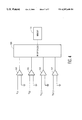
- FIG. 4 is a schematic diagram of the apparatus of the preferred embodiment of the invention.
- the present invention is applicable to automatic transfer switches, for example, automatic transfer switches of the type described in U.S. Pat. No. 5,748,432 to Przywozny et al.
- a rotating armature on which the main switch contacts are mounted is reciprocated by a solenoid between a normal position whereat the main contacts are connected to a normal voltage source and an alternate position whereat the main contacts are connected to an alternate or emergency voltage source.
- Actuation of the solenoid urges a linking arm to initiate rotation of a disc-shaped weight which is connected to the automatic transfer switch's armature. Rotation of the armature from a position at which its main contacts are connected to one of the normal and alternate voltage sources to the other source is completed due to the inertia of the rotating weight.
- the electronic control circuit for the automatic transfer switch determines the switch position from four voltages that exist in a conventional automatic transfer switch.
- the four voltages are the normal source voltage V S1 , the alternate or emergency source voltage V S2 , the coil control voltage V S1CC derived from the normal voltage source and the coil control voltage V S2CC derived from the alternate source.
- FIG. 1A there is shown an electronic control circuit 3 having contacts 11 which are connected across a main voltage source 13 and contacts 15 which are connected across an alternate voltage source 17 .
- a power outage-sensing double pole, double throw, relay 19 has its coil connected to the normal voltage source 13 , and contacts 21 which are movable between a position at which they are connected to respective normal source coil control voltage contacts 23 as shown in FIG. 1A when the relay coil is powered by the normal voltage source 13 , and a position at which the contacts 21 are connected to respective alternate source coil control voltage contacts 25 as shown in FIG. 1C when the relay coil is not powered by the normal voltage source 13 .
- a normal coil control voltage switch 27 can be closed to connect the normal voltage source 13 to the normal source coil control voltage contacts 23 and opened to disconnect the normal voltage source 13 from the normal source coil control voltage contacts 23 .
- An alternate coil control voltage switch 29 can be closed to connect the alternate voltage source 17 to the alternate source coil control voltage contacts 25 and opened to disconnect the alternate voltage source 17 from the alternate source coil control voltage contacts 25 .
- the rotating disc causes the alternate coil control voltage switch 29 to open thereby opening the coil control contacts 25 and removing power from the solenoid coil 26 .
- the transfer switch is again actuated to transfer the load 31 back to the normal voltage source 13 as follows.
- the rotating disc causes the normal coil control voltage switch 27 to open thereby opening the coil control contacts 23 and removing power from the solenoid coil 26 .
- the rotating disc causes the alternate source coil control voltage contacts 25 to close (FIGS. 2G and 2H) to prepare the switch for transfer of the load from the normal voltage source 13 to the alternate voltage source 17 in the event of another power failure or other event requiring alternate power.
- the switch contacts 5 come to rest on the normal source contacts 11 as seen in FIGS. 2I and 1J.
- FIG. 3 there is shown a flow chart for a method of determining the position of the main contacts 5 without need for special position contacts in an automatic transfer switch.
- This method can be executed by a computer in the electronic control circuit 3 which is programmed to compare the magnitudes of the voltage V S1 across the normal source contacts 11 , the voltage V S2 across alternate source contacts 15 , the voltage V S1CC across normal source coil control voltage contacts 23 , and the voltage V S2CC across alternate source coil control voltage contacts 25 , respectively, to a zero reference signal, i.e., to see of there is a voltage having a magnitude other than zero present.
- reference Y indicates the presence of a voltage, that is the magnitude of the monitored voltage is greater than zero
- N indicates the absence of a voltage, i.e., the magnitude of the monitored voltage is equal to zero.
- the transfer switch is in the disposition shown in FIG. 2A with the main contact 5 closed on the alternate source contacts 15 which have a nonzero voltage while the alternate source coil control voltage contacts 25 have no voltage. This condition is represented by condition # 5 in FIG. 3 .
- the transfer switch is in the disposition shown in FIG. 1A with the main contact 5 closed on the normal source contacts while the alternate source contacts 15 have a voltage as do the alternate source coil control voltage contacts 25 .
- This condition is represented by condition # 6 in FIG. 3 .
- the transfer switch is in the disposition shown in FIG. 1A with the main contact 5 closed on the normal source contacts 11 which have a voltage while the normal source coil control voltage contacts 23 have no voltage. This condition is represented by condition # 9 in FIG. 3 .
- the transfer switch is in the disposition shown in FIG. 2A with the main contact 5 closed on the alternate source contacts 15 while the normal source contacts 11 have a voltage as do the normal source coil control voltage contacts 23 .
- This condition is represented by condition # 11 in FIG. 3 .
- the transfer switch is in the disposition shown in FIG. 1A with the main contact 5 closed on the normal source contacts 11 while the alternate source contacts 15 have a voltage as do the alternate source coil control voltage contacts 25 .
- This condition is represented by condition # 14 in FIG. 3 .
- the transfer switch is in the disposition shown in FIG. 2A with the main contact 5 closed on the alternate source contacts 15 while the normal source contacts 11 have a voltage as do the normal source coil control voltage contacts 23 .
- This condition is represented by condition # 15 in FIG. 3 .
- the following conditions if sensed by the electronic control circuit 3 are error conditions, that is they cannot physically occur.
- Conditions 1 through 4 are ignored because neither source has voltage.
- Conditions 7 and 10 are error conditions because it is impossible for a coil control contact to have voltage across it if its respective source voltage is not available.
- Conditions 8 , 12 and 16 are error conditions because it is impossible for both sets of coil control contacts to be closed at the same time.
- Combination 13 is an error condition because if both sources are available voltage must be seen across one of the coil control contacts. The only exception to this is the case when the switch is moving and both sets of coil control contacts are open (see FIGS. 1 C and 2 C), but these cases are transient and normally of no consequence.
- signals having magnitudes proportional to the magnitudes of the normal source voltage V S1 , measured across contacts 11 , the alternate source voltage V S2 measured across contacts 15 , the normal coil control voltage V S1CC , measured across contacts 23 , and the alternate coil control voltage V S2CC , measured across contacts 25 are applied as input signals to respective comparators 101 , 103 , 105 , and 107 .
- Each of the comparators 101 , 103 , 105 , and 107 compares the magnitude of its respective input signal to a zero level signal.
- At the output of each comparator 101 , 103 , 105 , 107 there is produced a logic signal indicative of whether or not be corresponding input voltage is equal to 0 volts, i.e. whether or not a voltage is present.
- the logic signals at the outputs of the comparators 101 , 103 , 105 , and 107 are sampled at inputs of a microprocessor 109 connected to the comparators 101 , 103 , 105 , and 107 .
- the microprocessor 109 is programmed in accordance with the flow chart illustrated in FIG. 3 .
- signals indicative of the position of the automatic transfer switch's main contacts 5 or an indication of an error condition, as the situation warrants.
- the signals indicative of automatic transfer switch position or error indication can be applied as inputs to other circuitry in the electronic control circuit for automated decision making based on the disposition of the automatic transfer switch, and/or displayed on an indicator 111 as will be known to those skilled in the art.
Abstract
Description
| TABLE 1 | ||||
| |VS1|>0 | |VS2|>0 | |VS1CC|>0 | |VS2CC|>0 | Condition |
| no | no | no | no | 1. | Neither source has |
| voltage - irrelevant | |||||
| no | no | no | yes | 2. | Neither source has |
| voltage - irrelevant | |||||
| no | no | yes | no | 3. | Neither source has |
| voltage - irrelevant | |||||
| no | no | yes | yes | 4. | Neither source has |
| voltage - irrelevant | |||||
| no | yes | no | no | 5. | |
| connected to | |||||
| voltage source | |||||
| 17 | |||||
| no | yes | no | yes | 6. | |
| connected to | |||||
| voltage source | |||||
| 13 | |||||
| no | yes | yes | no | 7. | Error condition |
| no | yes | yes | yes | 8. | Error condition |
| yes | no | no | no | 9. | |
| connected to | |||||
| voltage source | |||||
| 13 | |||||
| yes | no | no | yes | 10. | Error condition |
| yes | no | yes | no | 11. | |
| connected to | |||||
| voltage source | |||||
| 17 | |||||
| yes | no | yes | yes | 12. | Error condition |
| yes | yes | no | no | 13. | Error condition |
| yes | yes | no | yes | 14. | |
| connected to | |||||
| voltage source | |||||
| 13 | |||||
| yes | yes | yes | no | 15. | |
| connected to | |||||
| voltage source | |||||
| 17 | |||||
| yes | yes | yes | yes | 16. | Error condition |
Claims (26)
Priority Applications (1)
| Application Number | Priority Date | Filing Date | Title |
|---|---|---|---|
| US09/289,916 US6297640B1 (en) | 1999-04-12 | 1999-04-12 | Transfer switch position sensing using coil control contacts |
Applications Claiming Priority (1)
| Application Number | Priority Date | Filing Date | Title |
|---|---|---|---|
| US09/289,916 US6297640B1 (en) | 1999-04-12 | 1999-04-12 | Transfer switch position sensing using coil control contacts |
Publications (1)
| Publication Number | Publication Date |
|---|---|
| US6297640B1 true US6297640B1 (en) | 2001-10-02 |
Family
ID=23113718
Family Applications (1)
| Application Number | Title | Priority Date | Filing Date |
|---|---|---|---|
| US09/289,916 Expired - Lifetime US6297640B1 (en) | 1999-04-12 | 1999-04-12 | Transfer switch position sensing using coil control contacts |
Country Status (1)
| Country | Link |
|---|---|
| US (1) | US6297640B1 (en) |
Cited By (27)
| Publication number | Priority date | Publication date | Assignee | Title |
|---|---|---|---|---|
| US20020195883A1 (en) * | 2001-04-19 | 2002-12-26 | Lazzaro Vince J. | Remotely actuated, circuit testing emergency stop apparatus and method |
| US6693248B1 (en) | 2002-10-28 | 2004-02-17 | General Electric Company | Methods and apparatus for transferring electrical power |
| US6815624B2 (en) | 2002-03-28 | 2004-11-09 | General Electric Company | Methods and apparatus for transferring electrical power |
| US7777600B2 (en) | 2004-05-20 | 2010-08-17 | Powerpath Technologies Llc | Eddy current inductive drive electromechanical liner actuator and switching arrangement |
| CN102157283A (en) * | 2011-05-16 | 2011-08-17 | 常熟开关制造有限公司(原常熟开关厂) | Control circuit for transfer switch |
| WO2013137971A1 (en) * | 2012-03-12 | 2013-09-19 | Eaton Corporation | Relay including processor providing control and/or monitoring |
| US8839815B2 (en) | 2011-12-15 | 2014-09-23 | Honeywell International Inc. | Gas valve with electronic cycle counter |
| US8899264B2 (en) | 2011-12-15 | 2014-12-02 | Honeywell International Inc. | Gas valve with electronic proof of closure system |
| US8905063B2 (en) | 2011-12-15 | 2014-12-09 | Honeywell International Inc. | Gas valve with fuel rate monitor |
| US8947242B2 (en) | 2011-12-15 | 2015-02-03 | Honeywell International Inc. | Gas valve with valve leakage test |
| US9074770B2 (en) | 2011-12-15 | 2015-07-07 | Honeywell International Inc. | Gas valve with electronic valve proving system |
| US9234661B2 (en) | 2012-09-15 | 2016-01-12 | Honeywell International Inc. | Burner control system |
| US9557059B2 (en) | 2011-12-15 | 2017-01-31 | Honeywell International Inc | Gas valve with communication link |
| US9645584B2 (en) | 2014-09-17 | 2017-05-09 | Honeywell International Inc. | Gas valve with electronic health monitoring |
| US9683674B2 (en) | 2013-10-29 | 2017-06-20 | Honeywell Technologies Sarl | Regulating device |
| US9835265B2 (en) | 2011-12-15 | 2017-12-05 | Honeywell International Inc. | Valve with actuator diagnostics |
| US9841122B2 (en) | 2014-09-09 | 2017-12-12 | Honeywell International Inc. | Gas valve with electronic valve proving system |
| US9846440B2 (en) | 2011-12-15 | 2017-12-19 | Honeywell International Inc. | Valve controller configured to estimate fuel comsumption |
| US9851103B2 (en) | 2011-12-15 | 2017-12-26 | Honeywell International Inc. | Gas valve with overpressure diagnostics |
| US9995486B2 (en) | 2011-12-15 | 2018-06-12 | Honeywell International Inc. | Gas valve with high/low gas pressure detection |
| US10024439B2 (en) | 2013-12-16 | 2018-07-17 | Honeywell International Inc. | Valve over-travel mechanism |
| US20190074714A1 (en) * | 2016-03-10 | 2019-03-07 | Robert Bosch Gmbh | Method and apparatus for supplying electric power to a device |
| US10422531B2 (en) | 2012-09-15 | 2019-09-24 | Honeywell International Inc. | System and approach for controlling a combustion chamber |
| US10503181B2 (en) | 2016-01-13 | 2019-12-10 | Honeywell International Inc. | Pressure regulator |
| US10564062B2 (en) | 2016-10-19 | 2020-02-18 | Honeywell International Inc. | Human-machine interface for gas valve |
| US10697815B2 (en) | 2018-06-09 | 2020-06-30 | Honeywell International Inc. | System and methods for mitigating condensation in a sensor module |
| US11073281B2 (en) | 2017-12-29 | 2021-07-27 | Honeywell International Inc. | Closed-loop programming and control of a combustion appliance |
Citations (1)
| Publication number | Priority date | Publication date | Assignee | Title |
|---|---|---|---|---|
| US5736594A (en) * | 1996-03-28 | 1998-04-07 | B J Services Company | Cementing compositions and methods using recycled expanded polystyrene |
-
1999
- 1999-04-12 US US09/289,916 patent/US6297640B1/en not_active Expired - Lifetime
Patent Citations (1)
| Publication number | Priority date | Publication date | Assignee | Title |
|---|---|---|---|---|
| US5736594A (en) * | 1996-03-28 | 1998-04-07 | B J Services Company | Cementing compositions and methods using recycled expanded polystyrene |
Cited By (38)
| Publication number | Priority date | Publication date | Assignee | Title |
|---|---|---|---|---|
| US6882155B2 (en) * | 2001-04-19 | 2005-04-19 | Vince J Lazzaro | Remotely actuated, circuit testing emergency stop apparatus and method |
| US20020195883A1 (en) * | 2001-04-19 | 2002-12-26 | Lazzaro Vince J. | Remotely actuated, circuit testing emergency stop apparatus and method |
| US6815624B2 (en) | 2002-03-28 | 2004-11-09 | General Electric Company | Methods and apparatus for transferring electrical power |
| US6693248B1 (en) | 2002-10-28 | 2004-02-17 | General Electric Company | Methods and apparatus for transferring electrical power |
| US8134438B2 (en) | 2004-05-20 | 2012-03-13 | Powerpath Technologies Llc | Electromechanical actuator |
| US7777600B2 (en) | 2004-05-20 | 2010-08-17 | Powerpath Technologies Llc | Eddy current inductive drive electromechanical liner actuator and switching arrangement |
| US8134437B2 (en) | 2005-05-20 | 2012-03-13 | Powerpath Technologies Llc | Eddy current inductive drive electromechanical linear actuator and switching arrangement |
| CN102157283A (en) * | 2011-05-16 | 2011-08-17 | 常熟开关制造有限公司(原常熟开关厂) | Control circuit for transfer switch |
| US9557059B2 (en) | 2011-12-15 | 2017-01-31 | Honeywell International Inc | Gas valve with communication link |
| US8899264B2 (en) | 2011-12-15 | 2014-12-02 | Honeywell International Inc. | Gas valve with electronic proof of closure system |
| US9995486B2 (en) | 2011-12-15 | 2018-06-12 | Honeywell International Inc. | Gas valve with high/low gas pressure detection |
| US9851103B2 (en) | 2011-12-15 | 2017-12-26 | Honeywell International Inc. | Gas valve with overpressure diagnostics |
| US8947242B2 (en) | 2011-12-15 | 2015-02-03 | Honeywell International Inc. | Gas valve with valve leakage test |
| US9074770B2 (en) | 2011-12-15 | 2015-07-07 | Honeywell International Inc. | Gas valve with electronic valve proving system |
| US9846440B2 (en) | 2011-12-15 | 2017-12-19 | Honeywell International Inc. | Valve controller configured to estimate fuel comsumption |
| US10851993B2 (en) | 2011-12-15 | 2020-12-01 | Honeywell International Inc. | Gas valve with overpressure diagnostics |
| US10697632B2 (en) | 2011-12-15 | 2020-06-30 | Honeywell International Inc. | Gas valve with communication link |
| US8839815B2 (en) | 2011-12-15 | 2014-09-23 | Honeywell International Inc. | Gas valve with electronic cycle counter |
| US8905063B2 (en) | 2011-12-15 | 2014-12-09 | Honeywell International Inc. | Gas valve with fuel rate monitor |
| US9835265B2 (en) | 2011-12-15 | 2017-12-05 | Honeywell International Inc. | Valve with actuator diagnostics |
| US9711309B2 (en) | 2012-03-12 | 2017-07-18 | Eaton Corporation | Relay including processor providing control and/or monitoring |
| WO2013137971A1 (en) * | 2012-03-12 | 2013-09-19 | Eaton Corporation | Relay including processor providing control and/or monitoring |
| US10422531B2 (en) | 2012-09-15 | 2019-09-24 | Honeywell International Inc. | System and approach for controlling a combustion chamber |
| US9234661B2 (en) | 2012-09-15 | 2016-01-12 | Honeywell International Inc. | Burner control system |
| US9657946B2 (en) | 2012-09-15 | 2017-05-23 | Honeywell International Inc. | Burner control system |
| US11421875B2 (en) | 2012-09-15 | 2022-08-23 | Honeywell International Inc. | Burner control system |
| US9683674B2 (en) | 2013-10-29 | 2017-06-20 | Honeywell Technologies Sarl | Regulating device |
| US10215291B2 (en) | 2013-10-29 | 2019-02-26 | Honeywell International Inc. | Regulating device |
| US10024439B2 (en) | 2013-12-16 | 2018-07-17 | Honeywell International Inc. | Valve over-travel mechanism |
| US9841122B2 (en) | 2014-09-09 | 2017-12-12 | Honeywell International Inc. | Gas valve with electronic valve proving system |
| US10203049B2 (en) | 2014-09-17 | 2019-02-12 | Honeywell International Inc. | Gas valve with electronic health monitoring |
| US9645584B2 (en) | 2014-09-17 | 2017-05-09 | Honeywell International Inc. | Gas valve with electronic health monitoring |
| US10503181B2 (en) | 2016-01-13 | 2019-12-10 | Honeywell International Inc. | Pressure regulator |
| US20190074714A1 (en) * | 2016-03-10 | 2019-03-07 | Robert Bosch Gmbh | Method and apparatus for supplying electric power to a device |
| US10756566B2 (en) * | 2016-03-10 | 2020-08-25 | Robert Bosch Gmbh | Method and apparatus for supplying electric power to a device |
| US10564062B2 (en) | 2016-10-19 | 2020-02-18 | Honeywell International Inc. | Human-machine interface for gas valve |
| US11073281B2 (en) | 2017-12-29 | 2021-07-27 | Honeywell International Inc. | Closed-loop programming and control of a combustion appliance |
| US10697815B2 (en) | 2018-06-09 | 2020-06-30 | Honeywell International Inc. | System and methods for mitigating condensation in a sensor module |
Similar Documents
| Publication | Publication Date | Title |
|---|---|---|
| US6297640B1 (en) | Transfer switch position sensing using coil control contacts | |
| US5357394A (en) | Circuit breaker with selective locking | |
| KR900000309B1 (en) | Braker pannel | |
| EP0833424A2 (en) | Live AC mains power selector for redundant systems | |
| EP0241270B1 (en) | Self-testing monitoring circuit | |
| CN105846806A (en) | Relay unit, control method for relay unit | |
| US4987513A (en) | Apparatus and method for selectively delaying the connection of an electrical supply voltage to an electrical load | |
| US6034447A (en) | Connector for consumer networks | |
| CN102099979B (en) | Method and the fault current protection device of self-test is performed by fault current protection device | |
| US6614635B2 (en) | Circuit provided with a protective function | |
| US4318093A (en) | Logic circuit monitor | |
| JPH04315298A (en) | Automatic duplex sensor switching device | |
| US20220258635A1 (en) | Charging device for a traction battery | |
| JPH0516846Y2 (en) | ||
| US6563326B1 (en) | Bus-driveable sensor apparatus with direction-dependent current/voltage characteristic curve and method for testing the apparatus | |
| JP3241073B2 (en) | Distribution system controller | |
| KR20040037811A (en) | Safety Relay | |
| KR20020062092A (en) | A device for monitoring door status of an elevator system and a method thereof and an elevator controller using the same | |
| JPS5942706Y2 (en) | Circuit element failure detection device | |
| JPH0134268Y2 (en) | ||
| KR20020074689A (en) | Apparatus and method for detecting electrovic relay | |
| JP3322324B2 (en) | Railroad crossing control device | |
| JPH0668683B2 (en) | Control output relay check circuit of controller | |
| JP2970164B2 (en) | Switching circuit | |
| KR0157942B1 (en) | Fault detecting device for underground switch |
Legal Events
| Date | Code | Title | Description |
|---|---|---|---|
| AS | Assignment |
Owner name: AUTOMATIC SWITCH COMPANY, NEW JERSEY Free format text: ASSIGNMENT OF ASSIGNORS INTEREST;ASSIGNOR:HAYES, JOHN;REEL/FRAME:009902/0316 Effective date: 19990407 |
|
| STCF | Information on status: patent grant |
Free format text: PATENTED CASE |
|
| FPAY | Fee payment |
Year of fee payment: 4 |
|
| AS | Assignment |
Owner name: ASCO POWER TECHNOLOGIES, L.P., NEW JERSEY Free format text: ASSIGNMENT OF ASSIGNORS INTEREST;ASSIGNOR:AUTOMATIC SWITCH COMPANY;REEL/FRAME:017125/0737 Effective date: 20000101 |
|
| FPAY | Fee payment |
Year of fee payment: 8 |
|
| FPAY | Fee payment |
Year of fee payment: 12 |
|
| AS | Assignment |
Owner name: JPMORGAN CHASE BANK, N.A., AS COLLATERAL AGENT, NE Free format text: SECURITY AGREEMENT;ASSIGNORS:ALBER CORP.;ASCO POWER TECHNOLOGIES, L.P.;AVOCENT CORPORATION;AND OTHERS;REEL/FRAME:040783/0148 Effective date: 20161130 Owner name: JPMORGAN CHASE BANK, N.A., AS COLLATERAL AGENT, NEW YORK Free format text: SECURITY AGREEMENT;ASSIGNORS:ALBER CORP.;ASCO POWER TECHNOLOGIES, L.P.;AVOCENT CORPORATION;AND OTHERS;REEL/FRAME:040783/0148 Effective date: 20161130 |
|
| AS | Assignment |
Owner name: JPMORGAN CHASE BANK, N.A., AS COLLATERAL AGENT, NE Free format text: SECURITY AGREEMENT;ASSIGNORS:ALBER CORP.;ASCO POWER TECHNOLOGIES, L.P.;AVOCENT CORPORATION;AND OTHERS;REEL/FRAME:040797/0615 Effective date: 20161130 Owner name: JPMORGAN CHASE BANK, N.A., AS COLLATERAL AGENT, NEW YORK Free format text: SECURITY AGREEMENT;ASSIGNORS:ALBER CORP.;ASCO POWER TECHNOLOGIES, L.P.;AVOCENT CORPORATION;AND OTHERS;REEL/FRAME:040797/0615 Effective date: 20161130 |
|
| AS | Assignment |
Owner name: ASCO POWER TECHNOLOGIES, L.P., NEW JERSEY Free format text: PARTIAL RELEASE OF SECURITY INTEREST;ASSIGNOR:JPMORGAN CHASE BANK, N.A.;REEL/FRAME:044638/0632 Effective date: 20171031 Owner name: ASCO POWER TECHNOLOGIES, L.P., NEW JERSEY Free format text: PARTIAL RELEASE OF SECURITY INTEREST;ASSIGNOR:JPMORGAN CHASE BANK, N.A.;REEL/FRAME:044652/0295 Effective date: 20171031 |