US6299841B1 - Bilaterally symmetrical battery powered microprocessor controlled lightweight hand-holdable electronic pipette - Google Patents

Bilaterally symmetrical battery powered microprocessor controlled lightweight hand-holdable electronic pipette Download PDF

Info

Publication number
US6299841B1
US6299841B1 US09/263,131 US26313199A US6299841B1 US 6299841 B1 US6299841 B1 US 6299841B1 US 26313199 A US26313199 A US 26313199A US 6299841 B1 US6299841 B1 US 6299841B1
Authority
US
United States
Prior art keywords
pipette
housing
user
control keys
handle
Prior art date
Legal status (The legal status is an assumption and is not a legal conclusion. Google has not performed a legal analysis and makes no representation as to the accuracy of the status listed.)
Expired - Fee Related
Application number
US09/263,131
Inventor
Kenneth Rainin
Christopher Kelly
James S. Petrek
Current Assignee (The listed assignees may be inaccurate. Google has not performed a legal analysis and makes no representation or warranty as to the accuracy of the list.)
Rainin Instrument Co Inc
Original Assignee
Rainin Instrument Co Inc
Priority date (The priority date is an assumption and is not a legal conclusion. Google has not performed a legal analysis and makes no representation as to the accuracy of the date listed.)
Filing date
Publication date
Application filed by Rainin Instrument Co Inc filed Critical Rainin Instrument Co Inc
Assigned to RAININ INSTRUMENT CO., INC. reassignment RAININ INSTRUMENT CO., INC. ASSIGNMENT OF ASSIGNORS INTEREST (SEE DOCUMENT FOR DETAILS). Assignors: KELLY, CHRISTOPHER, PETREK, JAMES S., RAININ, KENNETH
Priority to US09/263,131 priority Critical patent/US6299841B1/en
Priority to PCT/US2000/005880 priority patent/WO2000051739A1/en
Priority to CN00800284A priority patent/CN1302230A/en
Priority to PL00343820A priority patent/PL343820A1/en
Priority to EP00917769A priority patent/EP1076599A1/en
Priority to BRPI0005228-0A priority patent/BR0005228A/en
Priority to JP2000602398A priority patent/JP2002537981A/en
Priority to KR1020007012391A priority patent/KR20010043374A/en
Priority to TW089103940A priority patent/TW449503B/en
Priority to US09/931,964 priority patent/US20010055547A1/en
Publication of US6299841B1 publication Critical patent/US6299841B1/en
Application granted granted Critical
Assigned to RAININ INSTRUMENT, LLC reassignment RAININ INSTRUMENT, LLC ASSIGNMENT OF ASSIGNORS INTEREST (SEE DOCUMENT FOR DETAILS). Assignors: RAININ INSTRUMENT CO., INC.
Anticipated expiration legal-status Critical
Expired - Fee Related legal-status Critical Current

Links

Images

Classifications

    • GPHYSICS
    • G01MEASURING; TESTING
    • G01NINVESTIGATING OR ANALYSING MATERIALS BY DETERMINING THEIR CHEMICAL OR PHYSICAL PROPERTIES
    • G01N1/00Sampling; Preparing specimens for investigation
    • G01N1/02Devices for withdrawing samples
    • G01N1/10Devices for withdrawing samples in the liquid or fluent state
    • G01N1/14Suction devices, e.g. pumps; Ejector devices
    • BPERFORMING OPERATIONS; TRANSPORTING
    • B01PHYSICAL OR CHEMICAL PROCESSES OR APPARATUS IN GENERAL
    • B01LCHEMICAL OR PHYSICAL LABORATORY APPARATUS FOR GENERAL USE
    • B01L3/00Containers or dishes for laboratory use, e.g. laboratory glassware; Droppers
    • B01L3/02Burettes; Pipettes
    • B01L3/021Pipettes, i.e. with only one conduit for withdrawing and redistributing liquids
    • B01L3/0217Pipettes, i.e. with only one conduit for withdrawing and redistributing liquids of the plunger pump type
    • B01L3/0227Details of motor drive means
    • BPERFORMING OPERATIONS; TRANSPORTING
    • B01PHYSICAL OR CHEMICAL PROCESSES OR APPARATUS IN GENERAL
    • B01LCHEMICAL OR PHYSICAL LABORATORY APPARATUS FOR GENERAL USE
    • B01L3/00Containers or dishes for laboratory use, e.g. laboratory glassware; Droppers
    • B01L3/02Burettes; Pipettes
    • B01L3/0286Ergonomic aspects, e.g. form or arrangement of controls
    • BPERFORMING OPERATIONS; TRANSPORTING
    • B01PHYSICAL OR CHEMICAL PROCESSES OR APPARATUS IN GENERAL
    • B01LCHEMICAL OR PHYSICAL LABORATORY APPARATUS FOR GENERAL USE
    • B01L2200/00Solutions for specific problems relating to chemical or physical laboratory apparatus
    • B01L2200/08Ergonomic or safety aspects of handling devices
    • B01L2200/087Ergonomic aspects
    • BPERFORMING OPERATIONS; TRANSPORTING
    • B01PHYSICAL OR CHEMICAL PROCESSES OR APPARATUS IN GENERAL
    • B01LCHEMICAL OR PHYSICAL LABORATORY APPARATUS FOR GENERAL USE
    • B01L2300/00Additional constructional details
    • B01L2300/02Identification, exchange or storage of information
    • B01L2300/025Displaying results or values with integrated means
    • B01L2300/027Digital display, e.g. LCD, LED
    • YGENERAL TAGGING OF NEW TECHNOLOGICAL DEVELOPMENTS; GENERAL TAGGING OF CROSS-SECTIONAL TECHNOLOGIES SPANNING OVER SEVERAL SECTIONS OF THE IPC; TECHNICAL SUBJECTS COVERED BY FORMER USPC CROSS-REFERENCE ART COLLECTIONS [XRACs] AND DIGESTS
    • Y10TECHNICAL SUBJECTS COVERED BY FORMER USPC
    • Y10TTECHNICAL SUBJECTS COVERED BY FORMER US CLASSIFICATION
    • Y10T436/00Chemistry: analytical and immunological testing
    • Y10T436/25Chemistry: analytical and immunological testing including sample preparation
    • Y10T436/2575Volumetric liquid transfer

Definitions

  • the present invention relates to pipettes and more particularly to a battery powered microprocessor controlled electronic pipette which is light in weight and easily operated by a user over extended periods of time.
  • the present invention satisfies the foregoing need by providing an electronic pipette which is light in weight, comfortably holdable in either the right or left hand of a user and which is easily operated by the user to direct microprocessor controlled operation of the pipette through different user selected modes of operation for different user selected sample volume and speeds of operation.
  • the present invention comprises a bilaterally symmetrical design including an axially elongated hollow housing having a vertically extending longitudinal axis and vertically extending and substantially coaxial upper and lower portions.
  • the upper portion of the housing includes a forward compartment containing a forwardly facing alpha-numeric display adjacent a top of the housing.
  • the display is readily viewable by a user during all modes of operation of the pipette be the user right handed or left handed.
  • the forward compartment contains a plurality of columns of forwardly facing control keys as well as a plurality of forwardly facing trigger switches below the columns of control keys.
  • the display, columns of control keys and trigger switches are bilaterally symmetrical relative to the longitudinal axis of the housing.
  • the upper portion of the housing includes a rear compartment which contains a replaceable battery for powering a microprocessor and motor contained within the housing.
  • the lower portion of the housing comprises a vertically elongated handle which is coaxial with the longitudinal axis of the housing.
  • the handle has contiguous bilaterally symmetrical and vertically extending forward and rear portions for either right or left hand gripping by a user of the pipette.
  • the forward portion of the handle extends forward of the upper portion of the housing and extends vertically downward to a lower end of the housing.
  • the forward portion of the handle internally contains and shields an upper portion of a pipette tip ejector.
  • the pipette tip ejector has a thumb actuated push button located at a top of the forward portion of the handle and a vertically moveable tip ejector arm extending below the housing and vertically along a pipette tip mounting shaft to encircle the shaft adjacent a lower end thereof.
  • the pipette tip ejector is designed to eject a pipette tip from a lower end of the mounting shaft upon downward movement of the tip ejector arm. Such downward movement is in response to a downward thumb force exerted by the pipette user on the push button while the user is gripping the handle of the pipette.
  • the rear portion of the handle extends rearward from the forward portion and has a hook extending rearward from a back of an upper end of the handle.
  • the hook includes a downwardly curved lower surface for engaging an upper side of an index finger (or middle finger, if desired) of the user while the user is gripping the handle with the thumb of the user free to actuate any of the bilaterally symmetrical control keys, trigger switches and push button in any sequence desired. All this the user is free to do while clearly viewing the alpha numeric display as it responds to the actuation of the control keys and trigger switches.
  • the hook, forward and rear portion of the handle and pipette tip ejector including push button and ejector arm are all bilaterally symmetrical relative to the longitudinal axis of the housing.
  • the pipette of the present invention is easily and comfortably gripped by the user in either his or her left or right hand with the user's index finger under the hook at the rear of the handle.
  • the electronic pipette of the present invention is useable by the user over extended periods of time without unduly stressing the user's thumb, hand or forearm enabling accurate and repeatable operation of the pipette in all operational modes of pipette under control of the user.
  • FIG. 1 is a perspective view of a preferred embodiment of the present invention.
  • FIG. 2 is a front view of the electronic pipette of FIG. 1 .
  • FIG. 3 is a rear view of the electronic of the pipette FIG. 2 .
  • FIG. 4 is a right side view of the pipette of FIG. 2 .
  • FIG. 5 is a left side view of the pipette of FIG. 2 .
  • FIG. 6 is a top view of the pipette of FIG. 2 .
  • FIG. 7 is a bottom view of the pipette of FIG. 2 .
  • FIG. 8 is a cross sectional side view of the pipette of FIG. 2 showing the internal construction of the pipette and the component parts thereof.
  • the pipette 10 illustrated in the drawings comprises a bilaterally symmetrical lightweight hand holdable battery powered microprocessor controlled electronic pipette.
  • the pipette 10 includes an axially elongated hollow housing 12 having a vertically extending longitudinal axis 14 .
  • the housing 12 includes vertically extending and substantially coaxial upper and lower portions 16 and 18 .
  • the upper portion 16 of the housing includes a forward compartment 20 .
  • the compartment 20 contains and supports a forwardly facing alpha-numeric display 22 adjacent a top 24 of the housing.
  • the display is a LCD display of conventional design.
  • the forward compartment 20 contains and supports a plurality of columns (e.g.
  • vertically spaced upper control key 26 a and lower control key 26 b comprise a first column of control keys spaced to the left of the longitudinal axis 14 of the housing 12 .
  • vertically spaced upper control key 28 a and lower control key 28 b comprise a second column of control keys to the right of the longitudinal axis 14 a distance substantially equal to the spacing of the control keys 26 a, 26 b from the axis.
  • a trigger switch 30 is supported in the compartment 20 to the left of the axis 14 below the column of control keys 26 a, 26 b while a trigger switch 32 is supported in the compartment 20 to the right of the axis 14 below the second column of control keys 28 a, 28 b.
  • the right side of the trigger switch 30 and the left side of the trigger switch 32 lie substantially on a vertical plane including the longitudinal axis 14 .
  • the display 22 , the columns of control keys 26 a, 26 b and 28 a, 28 b and the trigger switches 30 and 32 are bilaterally symmetrical relative to the longitudinal axis 14 of the housing 12 and as will be described hereinafter in close proximity to a pipette user's thumb while the user is gripping the pipette 10 in his right or left hand and viewing the display 22 .
  • the upper portion 16 of the housing 12 includes a rear compartment 34 as shown in FIG. 8 .
  • the rear compartment 34 contains and supports a replaceable battery 36 for powering a microprocessor 38 and a motor 40 supported within the housing 12 for operation as described in detail in a concurrently filed patent application Ser. No. 09/263,132 abandoned, entitled “Improved Battery Powered Microprocessor Controlled Hand Portable Electronic Pipette”, assigned to the assignee of the present invention and incorporated herein by this reference.
  • the lower portion 18 of the housing 12 comprises a vertically elongated handle 42 coaxial with the longitudinal axis 14 of the housing.
  • the handle 42 comprises contiguous bilaterally symmetrical and vertically extending forward and rear portions 44 and 46 for hand gripping by a user of the pipette 10 .
  • the forward portion 44 of the handle 42 extends forward of the upper portion 16 of the housing 12 . It also extends vertically downward to a lower end 48 of the housing 12 to internally contain and shield an upper portion of a pipette tip ejector 50 having a thumb actuated push button 52 located at a top 54 of the forward portion.
  • the pipette tip ejector 50 includes a vertically moveable tip ejector arm 56 extending below the housing 12 and vertically along a pipette tip mounting shaft 58 to encircle a shaft adjacent a lower end 59 thereof.
  • the pipette tip ejector 50 may be of conventional design such as included in the well known PIPETMAN pipette or may take the form illustrated and described in U.S. Pat. No. 5,614,153 issued Mar. 25, 1997, assigned to the assignee of the present invention and incorporated herein by this reference. As described fully in the patent and as is well known with respect to the PIPETMAN pipette, it is a function of the pipette tip ejector 50 to eject a pipette tip, such as tip 60 , from the mounting shaft 58 in response to a downward thumb force exerted by user on the push button 52 .
  • the rear portion 46 of the handle 42 extends rearward from the forward portion 44 and includes a hook 62 extending rearward from a back 64 of an upper end 66 of the handle.
  • the hook preferably has a downwardly curved lower surface 68 for engaging an upper side of an index finger of the pipette user while the user is gripping the handle in either his or her right or left hand. This leaves the thumb of the user free to actuate any of the bilaterally symmetrical and closely spaced control keys ( 26 a, 26 b; 28 a, 28 b, ) trigger switches ( 30 , 32 ) and push button ( 52 ) in any sequence desired while clearly viewing the alpha-numeric display 22 as it responds to the actuation of the control keys and trigger switches.
  • the hook 62 , forward and rear portions of the handle 42 and the pipette tip ejector 50 including the push button 52 and ejector arm 54 are all bilaterally symmetrical relative to the longitudinal axis 14 of the housing. Further, it should be noted that an uppermost portion 70 of the lower surface of the hook 62 lies in substantially the same horizontal plane as a top 72 of the push button 52 . This further enhances the positioning of the user's hand in gripping the handle 42 such that freedom of movement is afforded the user's thumb to actuate the various closely spaced control keys and trigger switches as well as the push button when it is desired to eject a pipette tip from the mounting shaft of the pipette.
  • control key 26 a within the left side column preferably comprises a pipette mode of operation control key while the control key 26 b in the same column is designed to reset the mode of operation of the pipette all as described in the previously referenced concurrently filed patent application on the electronic pipette.
  • control keys 28 a and 28 b control the numeric value displayed by the display 22 as also described in detail the concurrently filed patent application.
  • actuation of the control key 28 a may increase the volume setting or speed of operation setting for the pipette 10 as indicated on the display 22 .
  • actuation of the control key 28 b may decrease the volume setting or speed of operation setting for the pipette 10 as indicated on the display 22 .
  • the first user pressed one of the trigger switches 30 , 32 may comprise an aspiration actuation trigger switch while the other one of the trigger switches may comprise a dispense actuation trigger switch.
  • either trigger switch 30 or 32 may actuate the next programmed step in the user selected mode of operation of the pipette.
  • the internal structure of the pipette provides a pipette having a center of gravity within the handle 42 .
  • This provides a balanced pipette which is neither top nor bottom heavy, free of undesired tipping when the user releases his or her grip on the handle and depends upon the hook 42 for support of the pipette.
  • FIG. 8 illustrates in cross section the internal structure of the electronic pipette.
  • the display 22 is secured by conventional means such as a retaining plate directly behind and within an upper window 74 in a bezel 76 comprising a front face of the upper portion 16 of the pipette housing 12 .
  • the display is electrically connected to a printed circuit board 78 mounted vertically within the upper portion of the housing 12 to define the forward compartment 20 for containing the display 22 , the control keys ( 26 a,b; 28 a,b ) and the trigger switches 30 and 32 as illustrated.
  • the control keys ( 26 a,b; 28 a,b ) are of conventional design and are each supported by a horizontal tube 80 within an opening 82 in a window 84 in the bezel 76 directly below the upper window 74 containing the display 22 .
  • the tubes 80 are moveable axially. Accordingly that the user's thumb in pressing on a forward exposed end of a tube will move a rear end of the tube and a conductive element carried thereby against the printed circuit board 78 to actuate the microprocessor 38 housed on the printed circuit board 78 .
  • Such actuation of the microprocessor may change or reset the mode of operation of the pipette or change the alpha-numeric displays on the display 22 as well as the volumes of liquid to be handled by and speed of operation of the pipette according to the user selected modes of operation as described in the concurrently filed patent application.
  • the volumetric settings and speed of aspiration and dispensing indications displayed by the display 22 are controlled by the keys 28 a and 28 b and are reflected in modifications of the operation of the pipette in the various 26 b modes selected by actuation of the control key 26 a, the control key 26 b being a “reset” key.
  • the trigger switches 30 , 32 on the other hand are in circuit with the microprocessor 38 as described in the concurrently filed patent application and are welded or otherwise connected to the bezel 76 . Accordingly a thumb actuation of one of the switches 30 , 32 will actuate operation of the pipette, such as aspiration, while thumb actuation of the other of the trigger switches 30 , 32 will actuate a different operation of the pipette and in at least a certain mode of operation will actuate a dispensing of a liquid by the pipette.
  • the battery 36 is contained in the rear compartment 34 between the printed circuit board 78 and a removable door 85 included in the upper portion 16 of the housing.
  • the battery 36 powers the microprocessor 38 and the motor 40 by electrical connections through a power jack connected to the printed circuit board 78 .
  • the motor 40 is located in the handle 42 of the pipette 10 below the printed circuit board 78 and is vertically secured by a support rib 86 on a backbone support 88 within the housing.
  • the motor 40 may be of conventional design and preferably is a stepper motor powered by the battery 36 and controlled by the microprocessor 38 in the manner described in the concurrently filed patent application.
  • an output shaft 89 extends vertically from the motor 40 and is connected in a conventional manner to a piston 90 such that rotation of a rotor within the motor produces axial movement of the output shaft 89 and corresponding axial movement of the piston 90 within the pipette tip mounting shaft 58 .
  • the pipette tip mounting shaft 58 is secured by a threaded nut 91 to a threaded collar 92 extending axially from a lower end of the handle 42 .
  • the piston 90 passes through a piston seal 93 which is secured in place around the piston by a spring loaded seal retainer 94 (the spring being removed for clarity of illustration).
  • the return spring in the pipette tip ejector 50 shown in FIG. 8 is also removed for clarity of illustration.
  • the return spring extends around a rod 96 between the push button 52 and ejector arm 54 secured at opposite ends of the rod. Downward movement of the push button 52 is opposed by the return spring and upon a release of the push button, the return spring returns the push button and the rod 96 to their uppermost position.
  • axial motion of the output shaft 89 of the motor 40 produces controlled axial movement of the piston 90 in the pipette tip mounting shaft 56 to draw or dispense liquid into or from a pipette tip 60 secured to a lower end of the shaft.
  • the user of the pipette grips the handle 42 in his or her right or left hand with his or her index or middle finger under the hook 62 . This leaves the user's thumb free to operate the push button 52 , the trigger switches 30 , 32 and/or control keys 26 a,b or 28 a,b in any sequence he or she desires while clearly viewing the display 22 .
  • the trigger switches and the control keys being bilaterally symmetrical relative to the longitudinal axis 14 of the pipette are easily actuated by the user's thumb without the exertion of forces which would lead to stress or strain of the user's thumb, hand or forearm. This allows the electronic pipette of the present invention to be operated in laboratories by technicians for long periods of time without resulting in fatigue or undesired strain on the thumb or hand of the user.
  • the display may be vertically elongated and the column of control keys 26 a and 26 b may be positioned on a left side of the display while the column of control keys 28 a and 28 b may be positioned on a right side of the display.
  • the bilateral symmetry of the pipette 10 is maintained and the keys and trigger switches are easily reached by the thumb of the user gripping the pipette. Accordingly, the invention is to be limited in scope only by the terms of the following claims.

Abstract

A bilaterally symmetrical lightweight hand holdable battery powered microprocessor controlled electronic pipette including an axially elongated hollow housing having a vertically extending longitudinal axis. An upper portion of the housing includes a forward compartment containing a forwardly facing alpha-numeric display, a plurality of columns of forwardly facing control keys and plurality of forwardly facing trigger switches arranged in a vertically spaced pattern such that a user in gripping a lower handle portion of the housing in either his or her right or left hand can easily reach with his thumb the control keys, trigger switches as well as a push button of a pipette tip ejector.

Description

FIELD OF INVENTION
The present invention relates to pipettes and more particularly to a battery powered microprocessor controlled electronic pipette which is light in weight and easily operated by a user over extended periods of time.
BACKGROUND
Since the first commercial introduction of a battery powered microprocessor controlled hand-holdable and easily transportable electronic pipettes by the Rainin Instrument Co., Inc., assignee of the present invention, it has been and continues to be the desire of all electronic pipette manufacturers to provide electronic pipettes which have the functional feel and operational capabilities of manual pipettes such as the world famous PIPETMAN pipette sold exclusively in the United States by the Rainin Instrument Co. for more than 25 years. Specifically in this regard, it continues to be the goal of all electronic pipette manufacturers to develop and produce electronic pipettes that are light in weight, easily holdable and transportable by a user and operational in several modes of operation over extended periods of time without creating physical stress and strain of the hand and forearms of the pipette user. The EDP electronic pipette of the Rainin Instrument Co. introduced in 1984 and its successor models addressed each of the foregoing design criteria. Following Rainin, other companies developing and manufacturing electronic pipettes have also addressed the same criteria and over the years electronic pipettes have become somewhat lighter in weight and more user friendly. However, the desire for an electronic pipette which closely approximates in feel and operational features those of the manual pipette has never been completely achieved. Accordingly, there continues to be a need for such an electronic pipette which is satisfied by the present invention.
SUMMARY OF INVENTION
Basically, the present invention satisfies the foregoing need by providing an electronic pipette which is light in weight, comfortably holdable in either the right or left hand of a user and which is easily operated by the user to direct microprocessor controlled operation of the pipette through different user selected modes of operation for different user selected sample volume and speeds of operation. In providing such a user friendly electronic pipette, the present invention comprises a bilaterally symmetrical design including an axially elongated hollow housing having a vertically extending longitudinal axis and vertically extending and substantially coaxial upper and lower portions. The upper portion of the housing includes a forward compartment containing a forwardly facing alpha-numeric display adjacent a top of the housing. Thus located, the display is readily viewable by a user during all modes of operation of the pipette be the user right handed or left handed. In addition to the display, the forward compartment contains a plurality of columns of forwardly facing control keys as well as a plurality of forwardly facing trigger switches below the columns of control keys. The display, columns of control keys and trigger switches are bilaterally symmetrical relative to the longitudinal axis of the housing. In addition, the upper portion of the housing includes a rear compartment which contains a replaceable battery for powering a microprocessor and motor contained within the housing. The lower portion of the housing comprises a vertically elongated handle which is coaxial with the longitudinal axis of the housing. The handle has contiguous bilaterally symmetrical and vertically extending forward and rear portions for either right or left hand gripping by a user of the pipette. The forward portion of the handle extends forward of the upper portion of the housing and extends vertically downward to a lower end of the housing. Preferably, the forward portion of the handle internally contains and shields an upper portion of a pipette tip ejector. Preferably, the pipette tip ejector has a thumb actuated push button located at a top of the forward portion of the handle and a vertically moveable tip ejector arm extending below the housing and vertically along a pipette tip mounting shaft to encircle the shaft adjacent a lower end thereof. Thus configured, the pipette tip ejector is designed to eject a pipette tip from a lower end of the mounting shaft upon downward movement of the tip ejector arm. Such downward movement is in response to a downward thumb force exerted by the pipette user on the push button while the user is gripping the handle of the pipette. The rear portion of the handle extends rearward from the forward portion and has a hook extending rearward from a back of an upper end of the handle. The hook includes a downwardly curved lower surface for engaging an upper side of an index finger (or middle finger, if desired) of the user while the user is gripping the handle with the thumb of the user free to actuate any of the bilaterally symmetrical control keys, trigger switches and push button in any sequence desired. All this the user is free to do while clearly viewing the alpha numeric display as it responds to the actuation of the control keys and trigger switches. In this regard, the hook, forward and rear portion of the handle and pipette tip ejector including push button and ejector arm are all bilaterally symmetrical relative to the longitudinal axis of the housing. Thus arranged, the pipette of the present invention is easily and comfortably gripped by the user in either his or her left or right hand with the user's index finger under the hook at the rear of the handle. This leaves the user's thumb free to actuate as desired any of the control keys or trigger switches which regulate the various modes of operation of the electronic pipette as well as the volumes of liquid aspirated and dispensed thereby during the several modes of operation of the pipette. All this is accomplished comfortably by the user while exerting minimal thumb forces on the control keys, trigger switches and push button. Thus, the electronic pipette of the present invention is useable by the user over extended periods of time without unduly stressing the user's thumb, hand or forearm enabling accurate and repeatable operation of the pipette in all operational modes of pipette under control of the user.
BRIEF DESCRIPTION OF DRAWINGS
FIG. 1 is a perspective view of a preferred embodiment of the present invention.
FIG. 2 is a front view of the electronic pipette of FIG. 1.
FIG. 3 is a rear view of the electronic of the pipette FIG. 2.
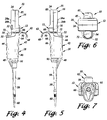
FIG. 4 is a right side view of the pipette of FIG. 2.
FIG. 5 is a left side view of the pipette of FIG. 2.
FIG. 6 is a top view of the pipette of FIG. 2.
FIG. 7 is a bottom view of the pipette of FIG. 2.
FIG. 8 is a cross sectional side view of the pipette of FIG. 2 showing the internal construction of the pipette and the component parts thereof.
DETAILED DESCRIPTION OF INVENTION
The pipette 10 illustrated in the drawings comprises a bilaterally symmetrical lightweight hand holdable battery powered microprocessor controlled electronic pipette. As illustrated, the pipette 10 includes an axially elongated hollow housing 12 having a vertically extending longitudinal axis 14. The housing 12 includes vertically extending and substantially coaxial upper and lower portions 16 and 18. The upper portion 16 of the housing includes a forward compartment 20. The compartment 20 contains and supports a forwardly facing alpha-numeric display 22 adjacent a top 24 of the housing. The display is a LCD display of conventional design. In addition, the forward compartment 20 contains and supports a plurality of columns (e.g. two) of forwardly facing control keys located below the display and plurality of forwardly facing trigger switches one located immediately below each of the columns control keys. In the illustrated embodiment of the present invention, vertically spaced upper control key 26 a and lower control key 26 b comprise a first column of control keys spaced to the left of the longitudinal axis 14 of the housing 12. Similarly, vertically spaced upper control key 28 a and lower control key 28 b comprise a second column of control keys to the right of the longitudinal axis 14 a distance substantially equal to the spacing of the control keys 26 a, 26 b from the axis. Also, a trigger switch 30 is supported in the compartment 20 to the left of the axis 14 below the column of control keys 26 a, 26 b while a trigger switch 32 is supported in the compartment 20 to the right of the axis 14 below the second column of control keys 28 a, 28 b. In fact, in the illustrated embodiment, the right side of the trigger switch 30 and the left side of the trigger switch 32 lie substantially on a vertical plane including the longitudinal axis 14.
In this regard, it is an important feature of the present invention that the display 22, the columns of control keys 26 a, 26 b and 28 a, 28 b and the trigger switches 30 and 32 are bilaterally symmetrical relative to the longitudinal axis 14 of the housing 12 and as will be described hereinafter in close proximity to a pipette user's thumb while the user is gripping the pipette 10 in his right or left hand and viewing the display 22.
In addition to the foreward compartment 20, the upper portion 16 of the housing 12 includes a rear compartment 34 as shown in FIG. 8. As illustrated, the rear compartment 34 contains and supports a replaceable battery 36 for powering a microprocessor 38 and a motor 40 supported within the housing 12 for operation as described in detail in a concurrently filed patent application Ser. No. 09/263,132 abandoned, entitled “Improved Battery Powered Microprocessor Controlled Hand Portable Electronic Pipette”, assigned to the assignee of the present invention and incorporated herein by this reference.
The lower portion 18 of the housing 12, on the other hand, comprises a vertically elongated handle 42 coaxial with the longitudinal axis 14 of the housing. The handle 42 comprises contiguous bilaterally symmetrical and vertically extending forward and rear portions 44 and 46 for hand gripping by a user of the pipette 10.
As illustrated, the forward portion 44 of the handle 42 extends forward of the upper portion 16 of the housing 12. It also extends vertically downward to a lower end 48 of the housing 12 to internally contain and shield an upper portion of a pipette tip ejector 50 having a thumb actuated push button 52 located at a top 54 of the forward portion. In addition, the pipette tip ejector 50 includes a vertically moveable tip ejector arm 56 extending below the housing 12 and vertically along a pipette tip mounting shaft 58 to encircle a shaft adjacent a lower end 59 thereof. The pipette tip ejector 50 may be of conventional design such as included in the well known PIPETMAN pipette or may take the form illustrated and described in U.S. Pat. No. 5,614,153 issued Mar. 25, 1997, assigned to the assignee of the present invention and incorporated herein by this reference. As described fully in the patent and as is well known with respect to the PIPETMAN pipette, it is a function of the pipette tip ejector 50 to eject a pipette tip, such as tip 60, from the mounting shaft 58 in response to a downward thumb force exerted by user on the push button 52.
As illustrated, the rear portion 46 of the handle 42 extends rearward from the forward portion 44 and includes a hook 62 extending rearward from a back 64 of an upper end 66 of the handle. The hook preferably has a downwardly curved lower surface 68 for engaging an upper side of an index finger of the pipette user while the user is gripping the handle in either his or her right or left hand. This leaves the thumb of the user free to actuate any of the bilaterally symmetrical and closely spaced control keys (26 a, 26 b; 28 a, 28 b,) trigger switches (30,32) and push button (52) in any sequence desired while clearly viewing the alpha-numeric display 22 as it responds to the actuation of the control keys and trigger switches. In this regard, the hook 62, forward and rear portions of the handle 42 and the pipette tip ejector 50 including the push button 52 and ejector arm 54 are all bilaterally symmetrical relative to the longitudinal axis 14 of the housing. Further, it should be noted that an uppermost portion 70 of the lower surface of the hook 62 lies in substantially the same horizontal plane as a top 72 of the push button 52. This further enhances the positioning of the user's hand in gripping the handle 42 such that freedom of movement is afforded the user's thumb to actuate the various closely spaced control keys and trigger switches as well as the push button when it is desired to eject a pipette tip from the mounting shaft of the pipette.
In this regard, the control key 26 a within the left side column preferably comprises a pipette mode of operation control key while the control key 26 b in the same column is designed to reset the mode of operation of the pipette all as described in the previously referenced concurrently filed patent application on the electronic pipette.
Further, as illustrated, in the right side column of control keys, the control keys 28 a and 28 b control the numeric value displayed by the display 22 as also described in detail the concurrently filed patent application. For example, actuation of the control key 28 a may increase the volume setting or speed of operation setting for the pipette 10 as indicated on the display 22. On the other hand, actuation of the control key 28 b may decrease the volume setting or speed of operation setting for the pipette 10 as indicated on the display 22.
Finally, as described in the concurrently filed patent application, in at least one mode of operation of the electronic pipette 10, the first user pressed one of the trigger switches 30,32 may comprise an aspiration actuation trigger switch while the other one of the trigger switches may comprise a dispense actuation trigger switch. In all other modes of pipette operation, either trigger switch 30 or 32 may actuate the next programmed step in the user selected mode of operation of the pipette.
More particularly, in the preferred embodiment of the pipette of the present invention, the internal structure of the pipette provides a pipette having a center of gravity within the handle 42. This provides a balanced pipette which is neither top nor bottom heavy, free of undesired tipping when the user releases his or her grip on the handle and depends upon the hook 42 for support of the pipette. Such balanced structure is represented most clearly in FIG. 8 which illustrates in cross section the internal structure of the electronic pipette.
In this regard, it should be noted that the display 22 is secured by conventional means such as a retaining plate directly behind and within an upper window 74 in a bezel 76 comprising a front face of the upper portion 16 of the pipette housing 12. The display is electrically connected to a printed circuit board 78 mounted vertically within the upper portion of the housing 12 to define the forward compartment 20 for containing the display 22, the control keys (26 a,b; 28 a,b) and the trigger switches 30 and 32 as illustrated.
The control keys (26 a,b; 28 a,b) are of conventional design and are each supported by a horizontal tube 80 within an opening 82 in a window 84 in the bezel 76 directly below the upper window 74 containing the display 22. The tubes 80 are moveable axially. Accordingly that the user's thumb in pressing on a forward exposed end of a tube will move a rear end of the tube and a conductive element carried thereby against the printed circuit board 78 to actuate the microprocessor 38 housed on the printed circuit board 78. Such actuation of the microprocessor may change or reset the mode of operation of the pipette or change the alpha-numeric displays on the display 22 as well as the volumes of liquid to be handled by and speed of operation of the pipette according to the user selected modes of operation as described in the concurrently filed patent application. In particular, the volumetric settings and speed of aspiration and dispensing indications displayed by the display 22 are controlled by the keys 28 a and 28 b and are reflected in modifications of the operation of the pipette in the various 26 b modes selected by actuation of the control key 26 a, the control key 26 b being a “reset” key.
The trigger switches 30,32 on the other hand are in circuit with the microprocessor 38 as described in the concurrently filed patent application and are welded or otherwise connected to the bezel 76. Accordingly a thumb actuation of one of the switches 30,32 will actuate operation of the pipette, such as aspiration, while thumb actuation of the other of the trigger switches 30,32 will actuate a different operation of the pipette and in at least a certain mode of operation will actuate a dispensing of a liquid by the pipette.
Further, as illustrated, the battery 36 is contained in the rear compartment 34 between the printed circuit board 78 and a removable door 85 included in the upper portion 16 of the housing. As described in the concurrently filed patent application, the battery 36 powers the microprocessor 38 and the motor 40 by electrical connections through a power jack connected to the printed circuit board 78. The motor 40 is located in the handle 42 of the pipette 10 below the printed circuit board 78 and is vertically secured by a support rib 86 on a backbone support 88 within the housing. The motor 40 may be of conventional design and preferably is a stepper motor powered by the battery 36 and controlled by the microprocessor 38 in the manner described in the concurrently filed patent application.
As illustrated, an output shaft 89 extends vertically from the motor 40 and is connected in a conventional manner to a piston 90 such that rotation of a rotor within the motor produces axial movement of the output shaft 89 and corresponding axial movement of the piston 90 within the pipette tip mounting shaft 58. The pipette tip mounting shaft 58, in turn, is secured by a threaded nut 91 to a threaded collar 92 extending axially from a lower end of the handle 42. The piston 90 passes through a piston seal 93 which is secured in place around the piston by a spring loaded seal retainer 94 (the spring being removed for clarity of illustration).
Also removed for clarity of illustration is the return spring in the pipette tip ejector 50 shown in FIG. 8. The return spring extends around a rod 96 between the push button 52 and ejector arm 54 secured at opposite ends of the rod. Downward movement of the push button 52 is opposed by the return spring and upon a release of the push button, the return spring returns the push button and the rod 96 to their uppermost position.
In the operation of the pipette 10, axial motion of the output shaft 89 of the motor 40 produces controlled axial movement of the piston 90 in the pipette tip mounting shaft 56 to draw or dispense liquid into or from a pipette tip 60 secured to a lower end of the shaft. In all of the operations of the pipette 10, the user of the pipette grips the handle 42 in his or her right or left hand with his or her index or middle finger under the hook 62. This leaves the user's thumb free to operate the push button 52, the trigger switches 30,32 and/or control keys 26 a,b or 28 a,b in any sequence he or she desires while clearly viewing the display 22. The trigger switches and the control keys being bilaterally symmetrical relative to the longitudinal axis 14 of the pipette are easily actuated by the user's thumb without the exertion of forces which would lead to stress or strain of the user's thumb, hand or forearm. This allows the electronic pipette of the present invention to be operated in laboratories by technicians for long periods of time without resulting in fatigue or undesired strain on the thumb or hand of the user.
While a particular preferred embodiment of the present invention has been described in detail herein, it is appreciated the changes and modifications may be made in the illustrated embodiment without departing from the spirit of the invention. For example, the display may be vertically elongated and the column of control keys 26 a and 26 b may be positioned on a left side of the display while the column of control keys 28 a and 28 b may be positioned on a right side of the display. The bilateral symmetry of the pipette 10 is maintained and the keys and trigger switches are easily reached by the thumb of the user gripping the pipette. Accordingly, the invention is to be limited in scope only by the terms of the following claims.

Claims (7)

What is claimed is:
1. A bilaterally symmetrical light weight microprocessor controlled electronic pipette holdable in either the right or left hand of a user with the thumb of user's hand holding the pipette free to actuate forwardly facing control keys to set the operation of the pipette and trigger switches to actuate operation of the pipette while viewing a forwardly facing display, the pipette comprising:
an axially elongated hollow housing having a vertically extending longitudinal axis and including vertically extending and substantially coaxial upper and lower portions;
the upper portion of the housing including a forward compartment and a rearward compartment,
the forward compartment containing
a forwardly facing alpha-numeric display adjacent a top of the housing,
a plurality of columns of forwardly facing pipette operation setting control keys and
a plurality of forwardly facing pipette operation actuating trigger switches below the columns of control keys,
the display, columns of control keys and trigger switches being bilaterally symmetrical relative to the longitudinal axis of the housing, and
the rear compartment containing a replaceable battery for powering a microprocessor and motor contained within the housing;
the lower portion of the housing comprising a vertically elongated handle coaxial with the longitudinal axis of the housing and having contiguous bilaterally symmetrical and vertically extending forward and rear portions for hand gripping by the user of the pipette,
the forward portion of the handle extending forward of the upper portion of the housing and extending vertically downward to a lower end of the housing, and
the rear portion of the handle extending rearward from the forward portion of the handle and having a hook extending rearward from a back of an upper end of the handle and having a downwardly curved lower surface for engaging an upper side of an index or middle finger of the user while the user is gripping the handle with the thumb of the user free to actuate any of the bilaterally symmetrical control keys and trigger switches in any sequence desired while clearly viewing the alpha-numeric display as it responds to the actuation of the control keys and trigger switches,
the hook, forward and rear portions of the handle all being bilaterally symmetrical relative to the longitudinal axis of the housing.
2. The pipette of claim 1 wherein the control keys are below the display.
3. The pipette of claim 1 wherein the forward portion of the handle internally contains and shields an upper portion of a pipette tip ejector having a thumb actuated push button located at a top of the forward portion and a vertically moveable tip ejector arm extending below the housing and vertically along a pipette tip mounting shaft to encircle the shaft adjacent a lower end thereof to eject a pipette tip from the shaft upon downward movement of the tip ejector arm in response to a downward thumb force exerted by the user on the push button, pipette tip ejector including the push button and the ejector arm being bilaterally symmetrical relative to the longitudinal axis of the pipette housing.
4. The pipette of claim 3 wherein an uppermost portion of the lower surface of the hook lies in substantially the same horizontal plane as a top of the push button.
5. The pipette of claim 1 wherein a first one of the columns of control keys comprise a pipette mode of operation control key and a key for resetting the mode of operation of the pipette.
6. The pipette of claim 5 wherein a second one of the columns of control keys comprise keys for controlling the numeric value displayed by the display.
7. The pipette of claim 5 wherein in at least one mode of operation of the pipette a first one of the trigger switches comprises an aspiration actuation trigger switch while a second one of the trigger switches comprises a dispense actuation trigger switch.
US09/263,131 1999-03-05 1999-03-05 Bilaterally symmetrical battery powered microprocessor controlled lightweight hand-holdable electronic pipette Expired - Fee Related US6299841B1 (en)

Priority Applications (10)

Application Number Priority Date Filing Date Title
US09/263,131 US6299841B1 (en) 1999-03-05 1999-03-05 Bilaterally symmetrical battery powered microprocessor controlled lightweight hand-holdable electronic pipette
JP2000602398A JP2002537981A (en) 1999-03-05 2000-03-03 Symmetric, lightweight, grippable, battery-operated, microprocessor-controlled electronic pipette
CN00800284A CN1302230A (en) 1999-03-05 2000-03-03 Bilaterally symmetrical battery powered microprocessor controlled lightweight hand-holdable electronic pipette
PL00343820A PL343820A1 (en) 1999-03-05 2000-03-03 Bilaterally symmetrical battery powered microprocessor controlled lightweight hand-holdable electronic pipette
EP00917769A EP1076599A1 (en) 1999-03-05 2000-03-03 Bilaterally symmetrical battery powered microprocessor controlled lightweight hand-holdable electronic pipette
BRPI0005228-0A BR0005228A (en) 1999-03-05 2000-03-03 Portable, lightweight, bilateral symmetry microprocessor controlled electronic pipette
PCT/US2000/005880 WO2000051739A1 (en) 1999-03-05 2000-03-03 Bilaterally symmetrical battery powered microprocessor controlled lightweight hand-holdable electronic pipette
KR1020007012391A KR20010043374A (en) 1999-03-05 2000-03-03 Bilaterally symmetrical battery powered microprocessor controlled lightweight hand-holdable electronic pipette
TW089103940A TW449503B (en) 1999-03-05 2000-03-06 Bilaterally symmetrical battery powered microprocessor controlled lightweight hand-hold electronic pipetie
US09/931,964 US20010055547A1 (en) 1999-03-05 2001-08-17 Bilaterally symmetrical battery powered microprocessor controlled lightweight hand-holdable electronic pipette

Applications Claiming Priority (1)

Application Number Priority Date Filing Date Title
US09/263,131 US6299841B1 (en) 1999-03-05 1999-03-05 Bilaterally symmetrical battery powered microprocessor controlled lightweight hand-holdable electronic pipette

Related Child Applications (1)

Application Number Title Priority Date Filing Date
US09/931,964 Continuation US20010055547A1 (en) 1999-03-05 2001-08-17 Bilaterally symmetrical battery powered microprocessor controlled lightweight hand-holdable electronic pipette

Publications (1)

Publication Number Publication Date
US6299841B1 true US6299841B1 (en) 2001-10-09

Family

ID=23000503

Family Applications (2)

Application Number Title Priority Date Filing Date
US09/263,131 Expired - Fee Related US6299841B1 (en) 1999-03-05 1999-03-05 Bilaterally symmetrical battery powered microprocessor controlled lightweight hand-holdable electronic pipette
US09/931,964 Abandoned US20010055547A1 (en) 1999-03-05 2001-08-17 Bilaterally symmetrical battery powered microprocessor controlled lightweight hand-holdable electronic pipette

Family Applications After (1)

Application Number Title Priority Date Filing Date
US09/931,964 Abandoned US20010055547A1 (en) 1999-03-05 2001-08-17 Bilaterally symmetrical battery powered microprocessor controlled lightweight hand-holdable electronic pipette

Country Status (9)

Country Link
US (2) US6299841B1 (en)
EP (1) EP1076599A1 (en)
JP (1) JP2002537981A (en)
KR (1) KR20010043374A (en)
CN (1) CN1302230A (en)
BR (1) BR0005228A (en)
PL (1) PL343820A1 (en)
TW (1) TW449503B (en)
WO (1) WO2000051739A1 (en)

Cited By (31)

* Cited by examiner, † Cited by third party
Publication number Priority date Publication date Assignee Title
US20010055547A1 (en) * 1999-03-05 2001-12-27 Rainin Instrument Co., Inc. Bilaterally symmetrical battery powered microprocessor controlled lightweight hand-holdable electronic pipette
US20020001545A1 (en) * 2000-06-26 2002-01-03 Cronenberg Richard A. Automatic pipette identification and detipping
US20020012613A1 (en) * 2000-06-26 2002-01-31 Scordato Richard E. Handheld pipette
US20020018734A1 (en) * 2000-08-03 2002-02-14 Ralf Braun Liquid dispensing and/or aspirating device to be operated manually repeatedly
US6428750B1 (en) * 2000-02-17 2002-08-06 Rainin Instrument, Llc Volume adjustable manual pipette with quick set volume adjustment
WO2003002257A2 (en) * 2001-06-29 2003-01-09 Bach David T Precision fluid dispensing system
US6540964B2 (en) * 1999-12-24 2003-04-01 Brand Gmbh + Co Kg Pipette for a pipette system
US6673318B1 (en) * 1999-05-31 2004-01-06 Bridgestone Corporation Pipette
US6740295B2 (en) * 1999-04-01 2004-05-25 Brand Gmbh + Co Kg Method and device for detecting the type of replaceable piston-cylinder units for pipetting or dosing apparatus
US20040149052A1 (en) * 2003-01-16 2004-08-05 Bernd Jagdhuber Proportioning device
US6787367B1 (en) * 1999-07-07 2004-09-07 Biohit Oyj Suction device
US20050118069A1 (en) * 2003-11-27 2005-06-02 Gilson S.A.S. Electronic pipette
US20050158214A1 (en) * 2001-10-16 2005-07-21 Richard Cote Hand-held pipettor
US20050175511A1 (en) * 2004-02-11 2005-08-11 Cote Richard A. Pipette tip mounting and ejection assembly and associated pipette tip
US20050247141A1 (en) * 2004-05-06 2005-11-10 Herbert Belgardt Pipette
US20060027033A1 (en) * 2002-10-16 2006-02-09 Richard Cote Hand-held pipette employing voice recognition control
US7093507B2 (en) 2003-05-12 2006-08-22 Bel-Art Products, Inc. Pipette control arrangement
US20070276546A1 (en) * 2006-05-23 2007-11-29 Eppendorf Ag Electronic metering apparatus for metering liquids
US20080206109A1 (en) * 2003-11-19 2008-08-28 Juha Telimaa Electric Pipette
US7540205B2 (en) 2007-09-17 2009-06-02 Viaflo Corp. Electronic pipettor
USD620602S1 (en) 2008-01-03 2010-07-27 Vistalab Technologies, Inc. Pipette
US7794664B2 (en) 2006-11-16 2010-09-14 Idexx Laboratories, Inc. Pipette tip
US20110195518A1 (en) * 2010-02-09 2011-08-11 Gjerde Douglas T Method and Apparatus for Pipette Tip Columns
US20110214518A1 (en) * 2008-09-23 2011-09-08 Ahn Biotechnologie Gmbh Electronic piston stroke pipette
US8033188B2 (en) 2007-09-17 2011-10-11 Integra Biosciences Corp. Pipettor software interface
US8057756B2 (en) * 2005-01-28 2011-11-15 Parker-Hannifin Corporation Sampling probe, gripper and interface for laboratory sample management systems
US20120055269A1 (en) * 2006-01-27 2012-03-08 Londo Thomas R Sampling probe, gripper and interface for laboratory sample management systems
US9604207B2 (en) * 2013-05-14 2017-03-28 A&D Company, Limited Pipette device
US10265695B2 (en) * 2016-03-22 2019-04-23 Icomes Lab Co., Ltd. Pipetting system
USD963886S1 (en) * 2021-03-12 2022-09-13 Mettler-Toledo Rainin, LLC Pipette body
USD969340S1 (en) 2014-01-13 2022-11-08 Gilson, Inc. Pipette

Families Citing this family (12)

* Cited by examiner, † Cited by third party
Publication number Priority date Publication date Assignee Title
JP2004337108A (en) * 2003-05-16 2004-12-02 Hitachi High-Technologies Corp Apparatus for refining nucleic acid, chip for catching nucleic acid and method for refining nucleic acid
DE102005014572B4 (en) * 2005-03-31 2007-01-04 Eppendorf Ag pipetting
DE102006032859A1 (en) * 2006-07-14 2008-01-17 Eppendorf Ag Electronic dosing device for dosing liquids
DE102006037213A1 (en) * 2006-08-09 2008-02-14 Eppendorf Ag Electronic dosing device for dosing liquids
US8900526B2 (en) * 2008-04-08 2014-12-02 Socorex Isba S.A. Joint for device for metering liquids
WO2010126459A1 (en) * 2009-04-27 2010-11-04 Ei Spectra, Llc Pipette instrument
WO2013005224A1 (en) * 2011-07-06 2013-01-10 Shan Chirag Narendrabhai Pipette controller
EP2641656B1 (en) * 2012-03-20 2019-02-20 Eppendorf AG Electrical pipette device and method for operating same
JP6353635B2 (en) * 2013-05-13 2018-07-04 株式会社アイカムス・ラボ Dispensing device
JP6353701B2 (en) * 2014-05-22 2018-07-04 株式会社アイカムス・ラボ Dispensing device
EP3399214B1 (en) 2017-05-05 2020-07-15 Eppendorf AG Electronic dosing drive
CN108330097B (en) * 2018-03-16 2020-10-23 天信和(苏州)生物科技有限公司 Cell culture and detection method

Citations (11)

* Cited by examiner, † Cited by third party
Publication number Priority date Publication date Assignee Title
US3915651A (en) * 1972-09-22 1975-10-28 Us Government Direct digital control pipette
US4369665A (en) * 1978-01-11 1983-01-25 Indicon Inc. Manually holdable automatic pipette
US4567780A (en) * 1984-03-12 1986-02-04 American Hospital Supply Corporation Hand-held pipette with disposable capillary
US4671123A (en) * 1984-02-16 1987-06-09 Rainin Instrument Co., Inc. Methods and apparatus for pipetting and/or titrating liquids using a hand held self-contained automated pipette
US4821586A (en) * 1988-02-25 1989-04-18 Medical Laboratory Automation, Inc. Programmable pipette
US4967606A (en) * 1988-04-29 1990-11-06 Caveo Scientific Instruments, Inc. Method and apparatus for pipetting liquids
US5002737A (en) * 1985-07-08 1991-03-26 Labsystems Oy Electrically operated pipette
US5343769A (en) * 1990-05-04 1994-09-06 Biohit Oy Procedure for filling and emptying a pipette, and pipette
US5389341A (en) * 1992-06-24 1995-02-14 Labsystems Oy Knob pipette
US5892161A (en) * 1997-09-09 1999-04-06 Tyco Group S.A.R.L. Transducer assembly for an electronically monitored mechanical pipette
US5983733A (en) * 1996-11-15 1999-11-16 Hamilton Company Manual pipette

Family Cites Families (1)

* Cited by examiner, † Cited by third party
Publication number Priority date Publication date Assignee Title
US6299841B1 (en) * 1999-03-05 2001-10-09 Rainin Instrument Co., Inc. Bilaterally symmetrical battery powered microprocessor controlled lightweight hand-holdable electronic pipette

Patent Citations (11)

* Cited by examiner, † Cited by third party
Publication number Priority date Publication date Assignee Title
US3915651A (en) * 1972-09-22 1975-10-28 Us Government Direct digital control pipette
US4369665A (en) * 1978-01-11 1983-01-25 Indicon Inc. Manually holdable automatic pipette
US4671123A (en) * 1984-02-16 1987-06-09 Rainin Instrument Co., Inc. Methods and apparatus for pipetting and/or titrating liquids using a hand held self-contained automated pipette
US4567780A (en) * 1984-03-12 1986-02-04 American Hospital Supply Corporation Hand-held pipette with disposable capillary
US5002737A (en) * 1985-07-08 1991-03-26 Labsystems Oy Electrically operated pipette
US4821586A (en) * 1988-02-25 1989-04-18 Medical Laboratory Automation, Inc. Programmable pipette
US4967606A (en) * 1988-04-29 1990-11-06 Caveo Scientific Instruments, Inc. Method and apparatus for pipetting liquids
US5343769A (en) * 1990-05-04 1994-09-06 Biohit Oy Procedure for filling and emptying a pipette, and pipette
US5389341A (en) * 1992-06-24 1995-02-14 Labsystems Oy Knob pipette
US5983733A (en) * 1996-11-15 1999-11-16 Hamilton Company Manual pipette
US5892161A (en) * 1997-09-09 1999-04-06 Tyco Group S.A.R.L. Transducer assembly for an electronically monitored mechanical pipette

Cited By (54)

* Cited by examiner, † Cited by third party
Publication number Priority date Publication date Assignee Title
US20010055547A1 (en) * 1999-03-05 2001-12-27 Rainin Instrument Co., Inc. Bilaterally symmetrical battery powered microprocessor controlled lightweight hand-holdable electronic pipette
US6740295B2 (en) * 1999-04-01 2004-05-25 Brand Gmbh + Co Kg Method and device for detecting the type of replaceable piston-cylinder units for pipetting or dosing apparatus
US6673318B1 (en) * 1999-05-31 2004-01-06 Bridgestone Corporation Pipette
US6787367B1 (en) * 1999-07-07 2004-09-07 Biohit Oyj Suction device
US6540964B2 (en) * 1999-12-24 2003-04-01 Brand Gmbh + Co Kg Pipette for a pipette system
US6428750B1 (en) * 2000-02-17 2002-08-06 Rainin Instrument, Llc Volume adjustable manual pipette with quick set volume adjustment
US20060104866A1 (en) * 2000-06-26 2006-05-18 Vistalab Technologies, Inc. Automatic pipette identification and detipping
US7416704B2 (en) 2000-06-26 2008-08-26 Vistalab Technologies, Inc. Handheld pipette
US20020012613A1 (en) * 2000-06-26 2002-01-31 Scordato Richard E. Handheld pipette
US6749812B2 (en) * 2000-06-26 2004-06-15 Vistalab Technologies Automatic pipette detipping
US8114362B2 (en) 2000-06-26 2012-02-14 Vistalab Technologies, Inc. Automatic pipette identification
US20020001545A1 (en) * 2000-06-26 2002-01-03 Cronenberg Richard A. Automatic pipette identification and detipping
US6841129B2 (en) * 2000-08-03 2005-01-11 Brand Gmbh + Co Kg Liquid dispensing and/or aspirating device to be operated manually repeatedly
US20020018734A1 (en) * 2000-08-03 2002-02-14 Ralf Braun Liquid dispensing and/or aspirating device to be operated manually repeatedly
AU2002320177B8 (en) * 2001-06-29 2003-03-03 Muniswamappa Anjanappa Precision fluid dispensing system
WO2003002257A3 (en) * 2001-06-29 2003-03-20 David T Bach Precision fluid dispensing system
AU2002320177B2 (en) * 2001-06-29 2008-01-24 Muniswamappa Anjanappa Precision fluid dispensing system
WO2003002257A2 (en) * 2001-06-29 2003-01-09 Bach David T Precision fluid dispensing system
US20050158214A1 (en) * 2001-10-16 2005-07-21 Richard Cote Hand-held pipettor
US8088342B2 (en) 2001-10-16 2012-01-03 Matrix Technologies Corporation Hand-held pipettor
US20060027033A1 (en) * 2002-10-16 2006-02-09 Richard Cote Hand-held pipette employing voice recognition control
US20040149052A1 (en) * 2003-01-16 2004-08-05 Bernd Jagdhuber Proportioning device
US7146867B2 (en) * 2003-01-16 2006-12-12 Eppendorf Ag Proportioning device
US7093507B2 (en) 2003-05-12 2006-08-22 Bel-Art Products, Inc. Pipette control arrangement
US20080206109A1 (en) * 2003-11-19 2008-08-28 Juha Telimaa Electric Pipette
US7648679B2 (en) 2003-11-19 2010-01-19 Thermo Fisher Scientific Oy Electric pipette
US20050118069A1 (en) * 2003-11-27 2005-06-02 Gilson S.A.S. Electronic pipette
US7976793B2 (en) 2003-11-27 2011-07-12 Gilson S.A.S. Electronic pipette
US20080271514A1 (en) * 2003-11-27 2008-11-06 Gilson S.A.S. System and Method for Precise Liquid Measurement in a Liquid Sampling Pipette
US8163256B2 (en) 2004-02-11 2012-04-24 Matrix Technologies Corporation Pipette tip mounting and ejection assembly and associated pipette tip
US20090280033A1 (en) * 2004-02-11 2009-11-12 Matrix Technologies Corporation Pipette Tip Mounting And Ejection Assembly And Associated Pipette Tip
US7641859B2 (en) * 2004-02-11 2010-01-05 Matrix Technologies Corporation Pipette tip mounting and ejection assembly and associated pipette tip
US20050175511A1 (en) * 2004-02-11 2005-08-11 Cote Richard A. Pipette tip mounting and ejection assembly and associated pipette tip
US20050247141A1 (en) * 2004-05-06 2005-11-10 Herbert Belgardt Pipette
US7421913B2 (en) * 2004-05-06 2008-09-09 Eppendorf Ag Pipette
US8057756B2 (en) * 2005-01-28 2011-11-15 Parker-Hannifin Corporation Sampling probe, gripper and interface for laboratory sample management systems
US20120055269A1 (en) * 2006-01-27 2012-03-08 Londo Thomas R Sampling probe, gripper and interface for laboratory sample management systems
US8096198B2 (en) * 2006-05-23 2012-01-17 Eppendorf Ag Electronic metering apparatus for metering liquids
US20070276546A1 (en) * 2006-05-23 2007-11-29 Eppendorf Ag Electronic metering apparatus for metering liquids
US7794664B2 (en) 2006-11-16 2010-09-14 Idexx Laboratories, Inc. Pipette tip
US20090196797A1 (en) * 2007-09-17 2009-08-06 Viaflo Corporation Electronic Pipettor With Improved Accuracy
US8033188B2 (en) 2007-09-17 2011-10-11 Integra Biosciences Corp. Pipettor software interface
US8122779B2 (en) 2007-09-17 2012-02-28 Integra Biosciences Corp. Electronic pipettor with improved accuracy
US7540205B2 (en) 2007-09-17 2009-06-02 Viaflo Corp. Electronic pipettor
USD620602S1 (en) 2008-01-03 2010-07-27 Vistalab Technologies, Inc. Pipette
US20110214518A1 (en) * 2008-09-23 2011-09-08 Ahn Biotechnologie Gmbh Electronic piston stroke pipette
US9242244B2 (en) * 2010-02-09 2016-01-26 Douglas T. Gjerde Method and apparatus for pipette tip columns
US20110195518A1 (en) * 2010-02-09 2011-08-11 Gjerde Douglas T Method and Apparatus for Pipette Tip Columns
US9604207B2 (en) * 2013-05-14 2017-03-28 A&D Company, Limited Pipette device
USD969340S1 (en) 2014-01-13 2022-11-08 Gilson, Inc. Pipette
USD998169S1 (en) 2014-01-13 2023-09-05 Gilson, Inc. Pipette
USD998818S1 (en) 2014-01-13 2023-09-12 Gilson, Inc. Cartridge for a pipette device
US10265695B2 (en) * 2016-03-22 2019-04-23 Icomes Lab Co., Ltd. Pipetting system
USD963886S1 (en) * 2021-03-12 2022-09-13 Mettler-Toledo Rainin, LLC Pipette body

Also Published As

Publication number Publication date
WO2000051739A1 (en) 2000-09-08
JP2002537981A (en) 2002-11-12
KR20010043374A (en) 2001-05-25
BR0005228A (en) 2007-05-29
PL343820A1 (en) 2001-09-10
CN1302230A (en) 2001-07-04
TW449503B (en) 2001-08-11
US20010055547A1 (en) 2001-12-27
EP1076599A1 (en) 2001-02-21

Similar Documents

Publication Publication Date Title
US6299841B1 (en) Bilaterally symmetrical battery powered microprocessor controlled lightweight hand-holdable electronic pipette
US7540205B2 (en) Electronic pipettor
JP6325600B2 (en) Electronic pipette with biaxial controller
US10105698B2 (en) Pipette with a tracking system
EP2065088B1 (en) A microprocessor controlled hand held portable electronic pipette
JP5047693B2 (en) Electronic weighing device
US7416704B2 (en) Handheld pipette
US7574929B2 (en) Controllable pipette
JP2008039785A (en) Electronic measuring apparatus
KR20110069825A (en) Electronic piston stroke pipette
US7972575B2 (en) Two-phase pipette
EP1087839B1 (en) Improved battery powered microprocessor controlled hand portable electronic pipette
MXPA00010803A (en) Bilaterally symmetrical battery powered microprocessor controlled lightweight hand-holdable electronic pipette
CN220610449U (en) Pipette for gene analyzer
JPH02194845A (en) Pipet

Legal Events

Date Code Title Description
AS Assignment

Owner name: RAININ INSTRUMENT CO., INC., CALIFORNIA

Free format text: ASSIGNMENT OF ASSIGNORS INTEREST;ASSIGNORS:RAININ, KENNETH;KELLY, CHRISTOPHER;PETREK, JAMES S.;REEL/FRAME:009824/0560

Effective date: 19990304

AS Assignment

Owner name: RAININ INSTRUMENT, LLC, CALIFORNIA

Free format text: ASSIGNMENT OF ASSIGNORS INTEREST;ASSIGNOR:RAININ INSTRUMENT CO., INC.;REEL/FRAME:012343/0670

Effective date: 20011012

REMI Maintenance fee reminder mailed
LAPS Lapse for failure to pay maintenance fees
STCH Information on status: patent discontinuation

Free format text: PATENT EXPIRED DUE TO NONPAYMENT OF MAINTENANCE FEES UNDER 37 CFR 1.362

FP Lapsed due to failure to pay maintenance fee

Effective date: 20051009