US6303389B1 - Rapid flow-through binding assay apparatus and method therefor - Google Patents
Rapid flow-through binding assay apparatus and method therefor Download PDFInfo
- Publication number
- US6303389B1 US6303389B1 US09/106,824 US10682498A US6303389B1 US 6303389 B1 US6303389 B1 US 6303389B1 US 10682498 A US10682498 A US 10682498A US 6303389 B1 US6303389 B1 US 6303389B1
- Authority
- US
- United States
- Prior art keywords
- top plate
- bottom plate
- assay
- plate
- membrane
- Prior art date
- Legal status (The legal status is an assumption and is not a legal conclusion. Google has not performed a legal analysis and makes no representation as to the accuracy of the status listed.)
- Expired - Fee Related
Links
Images


Classifications
-
- G—PHYSICS
- G01—MEASURING; TESTING
- G01N—INVESTIGATING OR ANALYSING MATERIALS BY DETERMINING THEIR CHEMICAL OR PHYSICAL PROPERTIES
- G01N33/00—Investigating or analysing materials by specific methods not covered by groups G01N1/00 - G01N31/00
- G01N33/48—Biological material, e.g. blood, urine; Haemocytometers
- G01N33/50—Chemical analysis of biological material, e.g. blood, urine; Testing involving biospecific ligand binding methods; Immunological testing
- G01N33/53—Immunoassay; Biospecific binding assay; Materials therefor
- G01N33/543—Immunoassay; Biospecific binding assay; Materials therefor with an insoluble carrier for immobilising immunochemicals
- G01N33/54366—Apparatus specially adapted for solid-phase testing
-
- B—PERFORMING OPERATIONS; TRANSPORTING
- B01—PHYSICAL OR CHEMICAL PROCESSES OR APPARATUS IN GENERAL
- B01L—CHEMICAL OR PHYSICAL LABORATORY APPARATUS FOR GENERAL USE
- B01L3/00—Containers or dishes for laboratory use, e.g. laboratory glassware; Droppers
- B01L3/50—Containers for the purpose of retaining a material to be analysed, e.g. test tubes
- B01L3/502—Containers for the purpose of retaining a material to be analysed, e.g. test tubes with fluid transport, e.g. in multi-compartment structures
- B01L3/5025—Containers for the purpose of retaining a material to be analysed, e.g. test tubes with fluid transport, e.g. in multi-compartment structures for parallel transport of multiple samples
- B01L3/50255—Multi-well filtration
-
- B—PERFORMING OPERATIONS; TRANSPORTING
- B01—PHYSICAL OR CHEMICAL PROCESSES OR APPARATUS IN GENERAL
- B01L—CHEMICAL OR PHYSICAL LABORATORY APPARATUS FOR GENERAL USE
- B01L3/00—Containers or dishes for laboratory use, e.g. laboratory glassware; Droppers
- B01L3/50—Containers for the purpose of retaining a material to be analysed, e.g. test tubes
- B01L3/508—Containers for the purpose of retaining a material to be analysed, e.g. test tubes rigid containers not provided for above
- B01L3/5085—Containers for the purpose of retaining a material to be analysed, e.g. test tubes rigid containers not provided for above for multiple samples, e.g. microtitration plates
- B01L3/50853—Containers for the purpose of retaining a material to be analysed, e.g. test tubes rigid containers not provided for above for multiple samples, e.g. microtitration plates with covers or lids
-
- B—PERFORMING OPERATIONS; TRANSPORTING
- B01—PHYSICAL OR CHEMICAL PROCESSES OR APPARATUS IN GENERAL
- B01L—CHEMICAL OR PHYSICAL LABORATORY APPARATUS FOR GENERAL USE
- B01L2200/00—Solutions for specific problems relating to chemical or physical laboratory apparatus
- B01L2200/04—Exchange or ejection of cartridges, containers or reservoirs
-
- B—PERFORMING OPERATIONS; TRANSPORTING
- B01—PHYSICAL OR CHEMICAL PROCESSES OR APPARATUS IN GENERAL
- B01L—CHEMICAL OR PHYSICAL LABORATORY APPARATUS FOR GENERAL USE
- B01L2300/00—Additional constructional details
- B01L2300/06—Auxiliary integrated devices, integrated components
- B01L2300/0681—Filter
-
- B—PERFORMING OPERATIONS; TRANSPORTING
- B01—PHYSICAL OR CHEMICAL PROCESSES OR APPARATUS IN GENERAL
- B01L—CHEMICAL OR PHYSICAL LABORATORY APPARATUS FOR GENERAL USE
- B01L2300/00—Additional constructional details
- B01L2300/08—Geometry, shape and general structure
- B01L2300/0809—Geometry, shape and general structure rectangular shaped
-
- B—PERFORMING OPERATIONS; TRANSPORTING
- B01—PHYSICAL OR CHEMICAL PROCESSES OR APPARATUS IN GENERAL
- B01L—CHEMICAL OR PHYSICAL LABORATORY APPARATUS FOR GENERAL USE
- B01L2400/00—Moving or stopping fluids
- B01L2400/04—Moving fluids with specific forces or mechanical means
- B01L2400/0475—Moving fluids with specific forces or mechanical means specific mechanical means and fluid pressure
- B01L2400/0487—Moving fluids with specific forces or mechanical means specific mechanical means and fluid pressure fluid pressure, pneumatics
- B01L2400/049—Moving fluids with specific forces or mechanical means specific mechanical means and fluid pressure fluid pressure, pneumatics vacuum
-
- B—PERFORMING OPERATIONS; TRANSPORTING
- B01—PHYSICAL OR CHEMICAL PROCESSES OR APPARATUS IN GENERAL
- B01L—CHEMICAL OR PHYSICAL LABORATORY APPARATUS FOR GENERAL USE
- B01L9/00—Supporting devices; Holding devices
- B01L9/52—Supports specially adapted for flat sample carriers, e.g. for plates, slides, chips
-
- Y—GENERAL TAGGING OF NEW TECHNOLOGICAL DEVELOPMENTS; GENERAL TAGGING OF CROSS-SECTIONAL TECHNOLOGIES SPANNING OVER SEVERAL SECTIONS OF THE IPC; TECHNICAL SUBJECTS COVERED BY FORMER USPC CROSS-REFERENCE ART COLLECTIONS [XRACs] AND DIGESTS
- Y02—TECHNOLOGIES OR APPLICATIONS FOR MITIGATION OR ADAPTATION AGAINST CLIMATE CHANGE
- Y02A—TECHNOLOGIES FOR ADAPTATION TO CLIMATE CHANGE
- Y02A50/00—TECHNOLOGIES FOR ADAPTATION TO CLIMATE CHANGE in human health protection, e.g. against extreme weather
- Y02A50/30—Against vector-borne diseases, e.g. mosquito-borne, fly-borne, tick-borne or waterborne diseases whose impact is exacerbated by climate change
-
- Y—GENERAL TAGGING OF NEW TECHNOLOGICAL DEVELOPMENTS; GENERAL TAGGING OF CROSS-SECTIONAL TECHNOLOGIES SPANNING OVER SEVERAL SECTIONS OF THE IPC; TECHNICAL SUBJECTS COVERED BY FORMER USPC CROSS-REFERENCE ART COLLECTIONS [XRACs] AND DIGESTS
- Y10—TECHNICAL SUBJECTS COVERED BY FORMER USPC
- Y10S—TECHNICAL SUBJECTS COVERED BY FORMER USPC CROSS-REFERENCE ART COLLECTIONS [XRACs] AND DIGESTS
- Y10S436/00—Chemistry: analytical and immunological testing
- Y10S436/807—Apparatus included in process claim, e.g. physical support structures
- Y10S436/809—Multifield plates or multicontainer arrays
-
- Y—GENERAL TAGGING OF NEW TECHNOLOGICAL DEVELOPMENTS; GENERAL TAGGING OF CROSS-SECTIONAL TECHNOLOGIES SPANNING OVER SEVERAL SECTIONS OF THE IPC; TECHNICAL SUBJECTS COVERED BY FORMER USPC CROSS-REFERENCE ART COLLECTIONS [XRACs] AND DIGESTS
- Y10—TECHNICAL SUBJECTS COVERED BY FORMER USPC
- Y10T—TECHNICAL SUBJECTS COVERED BY FORMER US CLASSIFICATION
- Y10T436/00—Chemistry: analytical and immunological testing
- Y10T436/25—Chemistry: analytical and immunological testing including sample preparation
- Y10T436/25375—Liberation or purification of sample or separation of material from a sample [e.g., filtering, centrifuging, etc.]
Definitions
- the invention relates generally to improved devices for performing binding assays and, more particularly, to rapid flow-through binding assay apparatus and methods.
- Binding assays are routinely used to screen for and diagnose a host of diseases and conditions, including Lyme disease, herpes, acquired immunodeficiency syndrome (AIDS), streptococcal infections, lupus and pregnancy. Such assays are relatively simple in theory, utilizing the binding affinity between two or more binding members to detect and/or quantify the presence of one of the members, referred to herein as the analyte. Binding members comprise a wide range of substances, including antigens, antibodies, haptens, complimentary nucleic acid sequences, ligands, small molecules and receptors. Antigen-antibody binding member pairs used in immunoassays currently enjoy the most widespread use.
- a common format of a binding assay involves immobilizing a binding member specific for the analyte on a paper-like sheet or membrane. The membrane is then contacted with the test sample and appropriate reagents under conditions allowing binding to occur between the immobilized binding member and any analyte in the sample, with means for detecting binding events also provided. Often a labeled second binding member which binds to the first binding member-analyte complex is added to provide a detectable signal on the membrane.
- the sandwich immunoassay is an example of one commonly used binding assay for antibody detection.
- the antigen is immobilized on a solid substrate.
- Antibody containing solution e.g., diluted serum
- Antibodies specific to the antigen bind to it, and unbound antibodies are then removed by buffer washes.
- a detection agent which may typically be a secondary antibody conjugated to an enzyme, is then incubated with the primary antibody-antigen complex.
- an enzyme substrate is added which is converted into a visual, detectable product whenever the enzyme is.
- Such multi-step sandwich immunoassays can be developed in many different ways depending on assay requirements.
- a Western Blot is another example of a commonly used immunoassay.
- the Western Blot method comprises a sequence of incubation and wash steps performed on a membrane bearing electrophoretically resolved antigen bands.
- the membrane is cut into narrow strips, each bearing the identical pattern of antigen bands.
- Strips are then processed in reagent solutions individually in narrow trays, each typically holding 0.5-2.0 ml.
- the strip is incubated with a blocking solution containing a non-specific protein, e.g., non-fat dry milk, bovine serum albumin, newborn calf serum or gelatin.
- a non-specific protein e.g., non-fat dry milk, bovine serum albumin, newborn calf serum or gelatin.
- the strip After washing off excess blocking solution with a wash buffer, typically a physiological saline buffer containing a low percentage of detergent, the strip is then incubated with antibody solution.
- Antibody solution may be diluted human or animal serum, cerebrospinal fluid, dried blood spot eluate, monoclonal antibody, to name a few. Unbound antibody is then washed off with buffer, and the strip is incubated in the detection reagent.
- the detection reagent could be goat-anti-human IgG-alkaline phosphatase conjugate.
- Unbound detection reagent is washed off with buffer, and finally the substrate (for alkaline phosphatase, a common substrate is 5-bromo-4-chloro-3-indolyl phosphate plus nitroblue tetrazolium) for the detection enzyme is added.
- the conversion of the substrate to a visually detectable product is allowed to proceed until optimal visualization of bands, and then substrate is washed away.
- the strip is typically dried, providing a permanent record of the assay result. Bands on the strip indicating antibody reactivity can be compared with control strips to determine the specificity of the immunoreaction.
- a positive test result is defined as the appearance of certain combinations of specific bands. For example, an HIV Western Blot test requires the presence of two bands to be considered positive, while a Lyme Western Blot test requires five out of ten bands to be positive for IgG, or two out of three bands to be positive for IgM.
- the Western Blot method involves incubating the membrane strips sequentially in reagent solutions usually contained in a tray.
- incubations with antibody solutions and detection reagents may take 30 minutes to several hours each. Wash steps may take 5-10 minutes each.
- the total time for processing a blot is therefore, not less than one hour, and is often several hours.
- a binding assay e.g., an immunoassay, including a Western Blot.
- the invention includes, inter alia, systems and methods for providing assay cassettes that can be employed during rapid flow-through binding assays.
- the assay cassettes can be disposable units suitable for one-time use and readily assembled to include a filter membrane carried between an upper plate and a lower plate.
- a pattern of channels can extend through the top plate to allow a fluid sample to be applied through the top plate and onto the filter.
- the bottom plate can include a plurality of channels that are aligned with the channel of the top plate and which will allow a negative pressure to be applied to the underside of the filter membrane to draw the sample through the filter.
- the cassette includes a frangible section that allows the cassette to be divided into at least a first and second component.
- the cassettes comprise a multi-channeled top plate that can be received into a multi-channeled bottom plate to define an interior chamber between the top plate and the bottom plate.
- a membrane having antibodies bound thereon can be received within the interior chamber and sandwiched between the top plate and bottom plate.
- the bottom plate and top plate can include an engagement mechanism, such as a notch and catch assembly that allows the top plate and bottom plate to be joined together.
- the bottom plate and top plate can be joined together in such a manner that a membrane placed into the interior chamber of the cassette is sandwiched between the bottom surface of the top plate and the top surface of the bottom plate.
- the assembled cassette with the membrane therein can be placed in an assay machine, such as a machine of the type described in U.S.
- the cassette can be compressed by the plates of a container that can compress together the top plate and bottom plate of the assay cassette to hold together the top plate and bottom plate with sufficient force that a series of substantially tight seals are formed around the portions of a filter membrane, sandwiched between the two plates, that are enclosed by the walls of the channels found in the top plate. Effectively, this causes the filter membrane to act as a series of strips of membrane wherein each strip is isolated from the other strips formed on the membrane by the grooves of the upper plate. In this way, the assay cassette can be employed for carrying out a plurality of reactions with reduced or eliminated cross-contamination.
- the invention assay cassettes described herein comprise a top plate having a frangible portion extending transversely across the top plate and a bottom plate having a peripheral side wall and being adapted to couple with said top plate to define an interior chamber capable of receiving a filter membrane.
- the frangible portion is formed by a score extending across the width of the top plate.
- the frangible portion can include a cavity or a frangible seal or any other mechanism suitable for allowing the top plate to be divided into separate components.
- the top plate can include a hinge for allowing the assay cassette to be swung open for giving access to the filter membrane stored therein.
- the assay cassette can include a top plate that has a recessed bottom surface which extends into a chamber a distance sufficient to butt against a membrane received therein.
- the top plate can also include a substantially open channel that extends through the top plate and provides an opening through the top plate to allow contact with a membrane within the chamber.
- the assay cassette can include open channels that allows a sample material to be delivered through an opening in the top plate and onto a membrane contained within the chamber of the assay cassette.
- the open channels can be formed in a pattern, such as a plurality of longitudinally extending channels, or as a plurality of concentric rings. However, it will be understood that any suitable pattern can be employed without departing from the scope of the invention, including systems with two, four, eight, or twenty-four channels, or openings formed as dots, ellipses, wells or any other suitable configuration.
- the assay cassette includes an engagement mechanism for holding the top plate together with the bottom plate.
- the engagement mechanism includes a catch for holding the top plate together with the bottom plate.
- the engagement mechanism allows for some vertical movement of the plates relative to each other. Accordingly, the top plate and bottom plate, in an engaged state, can be moved closer together, sandwich a filter membrane therebetween.
- the catch can be formed from a recessed surface in the top plate which will slidingly receive and engage with a surface protrusion located on the side wall of the bottom plate.
- the engagement mechanism can include a clasp capable of joining the top plate together with the bottom plate.
- the clasp can be a simple elastic element, such as a rubber band that can be fitted on the outside of the cassette when the top plate and bottom plate are joined together.
- Other mechanisms for joining and holding together the top plate and bottom plate can be practiced without departing from the scope of the invention.
- the assay cassette can include a vacuum port disposed in the bottom plate.
- the vacuum port can allow a vacuum to be applied to the interior chamber, and is understood to facilitate drawing fluid through the filter membrane.
- the vacuum port is formed in part by channels formed in the bottom plate of the cassette assembly. In a preferred practice, the channels in the bottom plate are aligned with the channels in the top plate to provide for fluid to be drawn through the channels in the top plate, and the membrane and into the channels of the bottom plate, where any excess fluid can be drawn off to a waste container.
- the assay cassette when assembled, is put into a container that is part of an agitator system for performing rapid flow-through assays.
- One such system provides a vacuum port that may be operatively-linked to a vacuum source.
- Test samples and assay reagents may be applied to the filter membrane of the assay cassette through the opening in the top plate and the vacuum source can apply a negative pressure to the channels bottom plate to draw material and reagents through the membrane.
- systems described herein can include systems for opening an assay cassette having a frangible section.
- These systems can include a base plate, and a top plate that is hingedly mounted to the base plate and spaced away from the base plate for defining a gap capable of receiving one end of the assay cassette. Once the assay cassette is received within the device, pivoting the top plate relative to the base plate provides a shearing force capable of opening the assay cassette.
- the assay cassettes described herein can be opened in response to a shear force applied to the frangible section, wherein in one embodiment the assay cassette opens by having the frangible section of the assay cassette break-off and separate from the cassette, or alternatively, the frangible section can break along one side of the assay cassette, with the other side still attached, yet in manner that allows the two sections to move relative to each other to provide access to the interior of the cassette.
- the membranes of the invention may be prepared by methods known to those skilled in the art.
- antigens may be applied to the membranes by electrophoresis and transblotting.
- Antigens or other binding members may also be applied directly to membranes by, for example, pens, brushes, spray devices, ink jet devices as well as flow-through devices such as the MinislotTM (Immunetics, Cambridge, Mass. ).
- the plates and other portions of the apparatus may be made by methods known in the art, and are preferably of a solution-resistant material, e.g., Plexiglas, molded plastics, aluminum, stainless steel or other synthetic materials.
- a test sample is allowed to come into contact with the surface of the membrane (on which a binding member specific for an analyte of interest is immobilized), through a multiple-channeled plate of a removable cassette of the invention.
- Appropriate volumes of test samples and assay reagents are placed, e.g., by pipetting, on the membrane through the channels.
- the test sample is drawn through the membrane under vacuum.
- the channels may then be flushed to rinse away unbound materials.
- additional reagents, indicators, or binding members can also be introduced into the channels, preferably under vacuum, to provide a detectable signal. If the test sample contains an analyte of interest, it will bind to the binding member specific for the analyte on the membrane.
- the removable cassettes described herein can be provided to the consumer for a single and disposable use.
- the membrane provided can include any desired binding members for detection of analytes of interest, including several different binding members, to permit simultaneous screening or the presence of more than one analyte.
- the membrane may also include only one type of binding member, allowing detection of a desired analyte from several test samples.
- the methods of the invention may also require smaller volumes of reagents than known methods and thus the apparatus and methods of the invention may provide additional costs savings.
- a further advantage of the apparatus and methods of the invention is the increased speed of assay as compared to conventional assay apparatus and methods.
- Yet a further advantage of the apparatus and methods of the invention is the increased clarity of the visual result as compared to conventional apparatus and methods.
- kits comprising a removable cassette having a membrane with preselected binding members specific for analytes of interest immobilized thereon, and reagents for carrying out the specific binding assay.
- the kit may further comprise instructions for use as well as appropriate packaging.
- FIG. 1 provides an exploded view of one assay cassette according to the invention
- FIG. 2 provides a cross-sectional view of the top plate of the assay cassette of FIG. 1;
- FIG. 3 depicts in greater detail the channels of the top plate of FIG. 2;
- FIG. 4 depicts the underside of the top plate of FIG. 2;
- FIG. 5 depicts in greater detail the latching mechanism of the assay cassette of FIG. 1;
- FIG. 6 depicts in greater detail the bottom plate of the assay cassette
- FIG. 7 provides an exploded view of the assay cassette of FIG. 1;
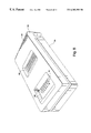
- FIG. 8 illustrates a chamber for holding an assay cassette during an assay such as a rapid flow-through assay
- FIG. 9 illustrates one system for opening the assay cassette of FIG. 1;
- FIG. 10 illustrates the cassette being opened by the device of FIG. 1;
- FIG. 11 illustrates the removal of the filter of an assay cassette that has been opened.
- an assay cassette for use during rapid flow-through assaying that includes a frangible section.
- the assay cassettes described herein can be adapted and modified to provide systems that can be employed in other types of assays, including any assay that requires filtering a sample material through a filter membrane, such as direct or sandwich assays.
- an analyte is bound to a binding member immobilized on the membrane, and a labeled second binding member is bound thereto to provide a detectable signal.
- labels or indicator schemes which provide a detectable signal that analyte binding has occurred can be employed with the systems described herein, including, for example, direct labels such as fluorescent, radioactive and chromophoric labels. Labels which may require development or enzymatic reagents, such as horseradish peroxidase or alkaline phosphatase, can also be utilized. Additionally, indirect label vehicles such as Protein A or avidin/biotin methods, know to those skilled in the art, can also be adapted for use with the apparatus and methods described herein. Accordingly, will be understood that the systems and methods described herein are exemplary and provided for purposes of illustrating the invention and that many modifications, substitutions, and additions can be made to the systems described herein without departing from the scope of the invention.
- each reagent or wash solution is added sequentially as soon as the previous solution has been fully aspirated through the membrane.
- the sequence of solutions generally comprises, in order: blocking solution (e.g., detergent Tween-20), primary antibody (diluted human serum), three washes with buffer containing phosphate-buffered saline and Tween-20 detergent, secondary antibody (e.g., diluted anti-human IgG-alkaline phosphatase conjugate), three more buffer washes, distilled water, and enzyme substrate (e.g., 5-bromo-4chloro-3-indoly-phosphate and nitroblue tetrazolium solution).
- blocking solution e.g., detergent Tween-20
- primary antibody diluted human serum
- secondary antibody e.g., diluted anti-human IgG-alkaline phosphatase conjugate
- enzyme substrate e.g., 5-bromo-4chloro-3-indoly-phosphate and nitroblue tetrazolium
- the assay device and binding assay of the invention are well-suited for conducting immunoassays for the presence of analytes in any biological material, e.g., an antibody or antigen analyte in human or animal serum, urine, stool, saliva or other body fluids, secretions or excretions. It will be appreciated, however, that the device and assays of the invention can be adapted to utilize the binding affinity of any binding member such as, for example, haptens, complimentary nucleic acid sequences, ligands, small molecules and receptors.
- the invention can also be used to screen for the presence of microbial organisms, including bacteria, viruses and fungi.
- the device of the invention can additionally be used to screen or otherwise characterize binding specificities of monoclonal antibodies, antibodies of different species and antibodies produced by genetic engineering or other in vitro techniques.
- binding assays which can be conducted with the device and in accordance with the principles of the invention include assays to detect the presence of antibodies specific for bacterial proteins of Borrelia burgdorferi which causes Lyme disease, for viral proteins of HSV which causes herpes, for viral HIV proteins implicated in acquired immunodeficiency syndrome (AIDS), for antigens specific to human chorionic gonadotropin (HCG) to detect pregnancy, for rheumatoid arthritis, and for a variety of bacterial and viral infections.
- AIDS acquired immunodeficiency syndrome
- HCG human chorionic gonadotropin
- the device and assays of the invention be used to screen for toxins such as, e.g., that of Clostridium difficile, and to screen for specific nucleic acid sequences to detect, e.g., pathogens, genetic defects, etc.
- kits comprising a top plate with channels and a membrane with preselected binding members specific for analytes of interest immobilized thereon, and packaging enclosing the top plate and membrane.
- Appropriate processing reagents for carrying out the specific binding assay may also be included, as well as instructions for use.
- To initiate the test the operator would need only to connect the disposable unit to a vacuum source and apply test solutions to the channels. Application of test solutions could be performed manually, or by a robotic liquid handling system under software control. In all cases, a visual or otherwise detectable pattern of reactivity, in the form of bands or otherwise, is generated in each test channel, and can be analyzed to obtain a test result.
- FIG. 1 depicts one embodiment of a cassette assembly according to the invention. Specifically, FIG. 1 depicts an assay cassette 10 , having a label 12 , a top plate 14 , a membrane 16 , a filter pad 18 , and a bottom plate 20 .
- the cassette 10 depicted in FIG. 1 is a disposable device, typically manufactured for one-time use and made out of plastic components which are readily manufactured by techniques well known in the art.
- FIG. 1 shows the relative order in which the above elements can be assembled together to provide an assay cassette suitable for rapid flow-through binding assays.
- FIG. 1 shows that the label 12 can attach to the top plate 14 and that the top plate 14 can fit over the bottom plate 20 so that the membrane 16 and the filter pad 18 fit within an interior chamber that is formed within the assay cassette 10 when the top plate 14 is fit over the bottom plate 20 .
- the elements depicted in FIG. 1 cooperate to form an assembly that can securely hold a membrane 16 between the two plates of the cassette.
- the top plate and bottom plate can be assembled in a manner that allows the plates to be moved closer together, for compressing the membrane 16 .
- This cassette assembly can then be employed within a device for performing a rapid flow-through assay, such as the devices described in the above-referenced U.S. patent application Ser. No. 09/045,630, filed Mar. 19, 1998.
- the label 12 depicted in FIG. 1 is a plastic label having a two-part adhesive backing which allows the label 12 to be affixed to the upper surface of the top plate 14 .
- the underside of the label 12 can have an adhesive material applied around the rim of the label 12 such that the label 12 can seal to the perimeter of the top plate 14 .
- the adhesive material is away from the channels 32 , and therefore away from the sample and reagent materials.
- the portion of the label 12 that fits over the channels 32 can be water proof, or other wise fluid resistant.
- the label 12 includes a sample/viewing window 22 disposed at one end of the label 12 .
- the sample/viewing window 22 is an aperture extending transversely along one end of the label 12 and providing an aperture through which a sample material can be delivered into the cassette assembly 10 .
- the depicted label 12 includes three peel-away labels 24 A- 24 C. Each of these three labels provides a set of data fields into which a lab technician can enter information. The information can include the patient identifier, such as the patient's name or social security number, the date of performing the assay, a barcode describing information about the assay, patient or lab, or any other relevant information. Each of the three peel-away labels 24 A- 24 C can be employed by the lab technician for labeling different components that are employed during the assay.
- one label can be left on the cassette device 10 , or located to a different location on the cassette device 10 .
- a second label can be maintained in-house, such as in an internal lab notebook.
- the third peel-away label can be employed for labeling a kit that includes the processed portions of the assay, such as a processed membrane.
- the depicted label 12 is waterproof, or otherwise fluid resistant for both top and bottom.
- the label 12 can be a multi-part label, wherein individual parts of the label can be peeled from the multi-part label and applied to different components of the test kit.
- the top plate 14 depicted in FIG. 1 includes a side wall 28 that surrounds the periphery of the plate 14 .
- a plurality of channels 32 that extend longitudinally across the top surface 30 .
- there are eight channels 32 however any number of channels can be employed depending on the application.
- the label 12 fits between the walls of a raised lip 35 which extends around three sides of the top surface of the top plate 14 .
- the depicted top plate 14 further includes a weakened portion 34 that in the depicted embodiment comprises a score disposed at one end of the top plate 14 and extending for the full width of the top plate 14 and being transverse to the channels 32 .
- FIG. 2 depicts in greater detail a portion of the top plate 14 .
- FIG. 2 provides a cut-away view and side perspective of one end of the top plate 14 .
- FIG. 2 shows in greater detail the frangible portion 34 that extends transversely across the top of the top plate 14 .
- the cut-away perspective of FIG. 2 shows that the top plate 14 has a recessed bottom wall 38 and has a catch wall 40 that has a plateau 42 that, as will be described in greater detail hereinafter, provides a surface for engaging against a catch on the bottom plate 20 depicted in FIG. 1 to engage the bottom plate 20 with the top plate 14 .
- FIG. 2 also illustrates in greater detail that the frangible portion 34 is formed as a V-shaped groove that extends partially into the top plate 14 .
- this groove provides a weakened section along the top plate 14 along which a fracture can more easily occur.
- a mechanical force such as a shear force applied to the top plate 14 can result in a fracture occurring along the frangible portion 34 such that the fracture travels downward from the grove 34 to the recessed bottom surface 38 .
- This results in the fracture of the top plate 14 fracturing into two components, a larger component and a smaller component.
- the weakened portion is depicted as a score that extends across the width of the top plate 14 .
- the frangible portion 34 can also include a concavity extending along the width of the top plate 14 wherein a fracture is more easy to occur, a breakable seal that can be pulled away by a lab technician to separate the top plate 14 into a larger component and a smaller component, or any other mechanism suitable for providing a weakened portion within the top plate 14 .
- Other embodiments can include notches that are square, or V-shaped, thin wall molded sections that in molding would provide internally molded knits or stress lines, or any other structure susceptible to breakage.
- the frangible portion 34 is depicted as being in the top surface of the top plate 14 at one end of the top plate 14 , it will be understood that the frangible portion 34 can be located at alternative positions, including at the other end of the top plate 14 , close to the center of the top plate 14 , at an edge of the top of 14 between the wall 14 and the side wall 28 , on the underside of the top plate 14 , in the side walls, or any other suitable location.
- the cassette can be made with clasps that allow a distal end of the assembled cassette to be separated from a proximal end of the cassette, therefore, providing a system wherein a section of the assembled cassette is detachable from the rest of the casette.
- the channels 32 and the top plate 14 can be described in greater detail.
- the channels 32 depicted in FIG. 3 are open grooves that extend longitudinally and that provide openings from the top surface 30 of the top plate 14 through to the bottom surface 38 of the top plate 14 . Accordingly, the channels 32 provide openings through which a substance can be delivered into the cassette assembly 10 .
- the channels 32 are alternately staggered to provide for greater visibility as the lab technician fills each of the grooves with sample material to be processed during the assay. It will be understood that each of the channels 32 can receive a separate sample of material to be assayed.
- channels 32 are fluidicly isolated from each other such that fluid cannot pass through the walls of the channels 32 to leave one channel and to enter into another channel. It will also be understood that the channels can be provided by other elements, including dots, and wells, similar to the dots found on a micro-titer plate, grooves, transverse channels or combinations thereof.
- FIG. 4 depicts in greater detail the bottom surface 38 of the top plate 14 . Specifically, FIG. 4 depicts that the bottom surface of 38 is recessed from the top of the top plate 14 and extends into the chamber defined by the top plate 14 and the side wall 28 . Additionally, FIG. 4 depicts that each of the channels 32 extends all the way through the top plate 14 to define a plurality of openings in the bottom surface 38 . FIG. 4 depicts that the catch wall 40 is formed into the side wall 28 of one end of the top plate 14 , however, it will be understood that a similar catch wall 40 is formed in the other sidewall of the cassette. As shown in FIG. 4 the catch wall 40 is centrally located and extends for a portion of the end of the side wall 28 .
- the end of the side wall 28 in which the catch wall 40 is located is, in the depicted embodiment, offset from the rest of the side wall 28 . Specifically, the side wall 28 steps inward toward the recessed bottom surface 38 as the wall 28 extends towards the catch wall 40 . This is understood to provide one end of the top plate 14 with a reduced width. This reduced width feature can be employed for orientation purposes, and specifically to allow the narrowed end of the top plate 14 to be received within a device for fracturing the top plate 14 . Such a device will be described in greater detail hereinafter.
- FIG. 5 depicts in greater detail the engagement mechanism of the cassette assembly 10 .
- FIG. 5 provides a cross-sectional view of the cassette assembly, showing the engagement mechanism that is formed by the catch wall 40 located in the end wall 28 of the top plate 14 and by the lock wall 44 located on the end wall of the bottom plate 20 .
- the locking wall 44 includes a lip 48 that extends outwardly from the side wall of the bottom plate 20 .
- the lip 48 can fit into the chamber defined by the catch wall 40 that is notched into the side wall 28 of the top plate 14 .
- the lip 48 Upon insertion of the locking wall 44 into the cavity formed above the catch wall 40 , the lip 48 extends into the cavity and butts against the catch wall 40 , which acts as a mechanical stop preventing the lip 48 from moving downwardly.
- a gap 46 that allows the top plate 14 to travel downward toward the bottom plate 20 and compress the membrane 16 held between the top plate and the bottom plate. Accordingly, upon insertion of the locking wall 44 into the cavity formed above the catch wall 40 , the bottom plate 20 is stopped from moving downwardly and away from the top plate, thereby being engaged therewith, however, the top plate 14 can be move downward toward the bottom plate 20 to allow further compression of the membrane 16 . Such movement can occur when the assay cassette 10 is placed within a container, such as that described hereinafter with reference to FIG. 8, and the top plate of the container is brought down and pushed against the top plate 14 of the assay cassette.
- the assay cassette 10 has been depicted having the locking walls 48 and catch wall 40 as the engaging mechanism, it will be understood that other devices can be employed for engaging the top plate 14 with the bottom plate 20 .
- a clasp mechanism can be employed which can wrap around the exterior of the assay cassette 10 , wrapping around both the top plate 14 and the bottom plate 20 and thereby preventing the plates from separating.
- a screw mechanism can be employed for allowing a screw to be threaded through both the top plate 14 and the bottom plate 20 , thereby joining the two plates together.
- Gaskets can be applied around the periphery of the plate, to allow the plates to seal and to allow further compression of the plates, and the membrane Additionally, other techniques can be employed, such as ultra-sonic welding, fast drying glues and adhesives, which can be applied in various ways for permanently joining the top plate 14 to the bottom plate 20 , and other mechanisms can be employed for allowing the plates to be brought closer together and for allowing the membrane 16 to be compressed.
- FIG. 5 further depicts the membrane 16 , and filter pad 18 , which are disposed between the top plate 14 and the bottom plate 20 .
- FIG. 5 shows the filter pad 18 supports the membrane 16 , and provides a raised surface upon which the membrane 16 can be seated.
- FIG. 5 further depicts that the coupling of the bottom plate 20 with the top plate 14 forms an interior chamber 15 in which are disposed the membrane 16 and the filter pad 18 .
- the filter pad 18 is dimensionally adapted to raise the membrane 16 into engagement with the recessed bottom surface 38 of the top plate 14 when the top plate 14 is joined to the bottom plate 20 . In this way, the membrane 16 is sandwiched within the assay cassette 10 .
- the membrane 16 can be a nitrocellulose membrane bearing electrophoretically resolved antigens of Borrelia burgdorferi was prepared by standard blotting procedures (e.g., Towbin, H., Stehelin, T. and Gordon, J., Proc. Nat. Acad. Sci. U.S.A. 76:4350-4354 (1979)), then washed 30 minutes in distilled water. Additional stripes of defined antigens may be applied to the membrane at this point by non-electrophoretic methods.
- the nitrocellulose membrane can have a 0.2 ⁇ pore size and can be obtained from commercial suppliers such as Schleicher & Schuell (Keene, N.H.), Whatman, Inc. (Fairfield, N.J.), or others.
- the nitrocellulose membrane can be cut to fit the cassette, such as being cut to 2′′ wide ⁇ 4′′ long.
- the wet membrane can be placed over an identically sized piece of dry filter paper.
- a variety of filter papers may be used, but a paper specifically intended for wicking is optimal, such as. #320 paper from Ahlstrom Filtration Inc. (Mount Holly Springs, Pa. ), a 2.5 mm thick blotting paper.
- the bottom 20 includes a weakened portion 52 that, when the top plate 14 is joined to the bottom plate 20 is positioned in opposition to the frangible portion 34 of top plate 14 .
- This alternate embodiment allows a shear force to fracture the top plate 14 and the bottom plate 20 .
- FIG. 6 depicts in greater detail the bottom plate 20 . Specifically, FIG. 6 depicts the bottom plate 20 , the side wall 60 , alignment pins 62 , bottom surface 64 , vacuum slots 68 , and the locking wall 44 .
- the side wall 60 forms a peripheral wall around the bottom plate 20 , running along the full perimeter of the bottom surface 64 .
- the alignment pins 62 are mounted to the side wall and dimensionally adapted to extend into the interior of the bottom plate 20 a distance sufficient to allow for proper alignment of the filter pad 18 and filter 16 that are disposed within the bottom plate 20 .
- FIG. 6 further depicts the locking wall 44 that is formed integrally into one part of side wall 60 . Specifically, the depicted locking wall 44 is formed by two groves 70 that extend through the side wall 60 . Accordingly, the locking wall 44 lacks side wall support and is anchored only at the bottom section of locking wall 44 .
- the side wall 44 can deflect laterally, either inwardly or outwardly relative to the interior of the bottom plate 20 .
- FIG. 6 further depicts that the locking wall 44 has a outwardly extending protrusion that forms the lip 48 .
- This outwardly extending protrusion causes the locking wall 44 to deflect inwardly as the bottom plate is being slid into the top plate.
- the resilient locking wall 44 drives the protrusion into the cavity causing the lip 48 to butt against the locking wall 40 engaging the bottom plate with the top plate.
- FIG. 7 provides an exploded view with an upward looking prospective of the assay cassette 10 depicted in FIG. 1 .
- FIG. 7 shows the assay cassette 10 which includes the label 12 , the top plate 14 , the membrane 16 , the filter pad 18 and the bottom plate 20 . From the prospective provided by FIG. 7 it can be seen that the recessed bottom surface 38 of the top plate 14 is brought down upon the membrane 16 to sandwich the membrane 16 and filter pad 18 between the recessed bottom surface 38 and the bottom plate 20 .
- FIG. 7 also illustrates the bumps 78 that are optionally provided on the bottom surface 76 of the bottom plate 20 .
- the bumps 78 are located on the ribs 36 between the channels 68 that extend through the bottom plate 20 .
- the bumps 78 on the ribs 36 help push the filter pad 18 against the bottom surface of the top plate 14 , by allowing the vacuum applied to the underside of the cassette to act on the cassette and pull down the membrane and filter pad.
- there are two sets of bumps 78 there are two sets of bumps 78 , however, any suitable number and pattern can be employed to provide for optimal pressure on the filter pad.
- the depicted bumps 78 include an upper set and a lower set, each of which is longitudinally spaced apart.
- the pairs of bumps provide a gap between the bottom surface 76 of the cassette 10 and the bottom surface of the chamber in which the cassette 10 can be received during a rapid flow through assay.
- One such chamber is described in the above referenced patent application entitled “Systems and Method for Rapid Blot Screening”, and another chamber is described with reference to FIG. 8 .
- the gap provided by the bumps 78 allows for a negative pressure within the interior of the chamber holding the assay cassette 10 to be applied through the grooves 68 to the underside of the filter pad 18 and membrane 16 . In this way, a negative pressure applied to the chamber holding the assay cassette 10 can act on a sample material applied through the sample window 20 in label 12 to pull sample material through the membrane 16 and filter pad 18 and to be drawn through the grooves 68 .
- FIG. 8 illustrates a chamber 80 that includes a lid 82 that is hingedly mounted to a base plate 84 , and then further includes a label window 88 and a pipette window 90 .
- the assay cassette 10 can be received within the chamber 80 to be held there during the rapid flow through assay.
- the lid 82 can seal against the base plate 84 , wherein the base plate 84 can have a perimeter gasket that allows a vacuum seal to be formed between the lid 80 and the base plate 84 .
- a gasket seal can fit above the perimeters of the underside of the label viewing window 88 and the pipette window 90 .
- each of the windows comprises a transparent surface located within the body of the lid 80 .
- the transparent servers provides a viewing structure that allows for viewing of the label 12 , and for viewing of the channels of the assay cassette 10 .
- no viewing windows are provided.
- the chamber 80 can further include a vacuum port (not shown) that can be disposed in the bottom plate 84 and that can be employed for applying a negative pressure to the interior of the chamber 80 . As discussed above with a reference FIG. 7 this negative pressure can draw sample and other fluid material through the membrane 16 for performing the flow through assay.
- the base plate 84 includes a perimeter gasket against which an assay cassette received within the chamber 80 can sit.
- the gasket provides a vacuum seal that forms above the perimeter of the bottom surface 76 of the bottom plate 20 of the assay cassette 10 .
- a vacuum port (not shown) in the bottom surface of the bottom plate 84 can be aligned to apply a negative pressure against the bottom surface 76 of the assay cassette 10 .
- the chamber gasket seal between the assay cassette 10 and the bottom plate 84 of the container 80 provides a vacuum tight chamber that can maintain the negative pressure so that it is transmitted to the sample material being processed in the assay cassette 10 .
- the assay cassette 10 can be opened to allow a lab technician to remove the membrane 16 for subsequent processing and analysis.
- the cassette 10 can be placed in an opening device, such as the device 100 depicted in FIG. 9 .
- the device 100 can include an upper plate 102 that is hingedly mounted to a lower plate 104 , by the hinge 108 .
- the upper plate 102 is spaced away from the base plate 104 a distance sufficient to allow the assay cassette 10 to fit within the gap formed between the two plates.
- the assay cassette 10 fits within the gap and comes to rest against the arm 110 that acts as a stop to prevent further movement of the assay cassette 10 .
- the arm 110 is disposed on the upper plate 102 a distance sufficient to dispose the frangible portion 34 at a point at which sheer forces will act when the upper plate 102 is pivoted downwardly toward the base plate 104 .
- pivoting the upper plate 102 toward the base plate 104 causes sheer forces to act on the frangible portion 34 allowing the one end of the assay cassette 10 to break off from the other end.
- the portion of the assay cassette 10 that breaks off 116 is allowed to fall away from the device 100 and can land into a container, such as a jelly container, that can be adapted for collecting waste product that can be disposed of properly later.
- a container such as a jelly container
- FIG. 11 depicts that once the end portion of the assay cassette 10 is fractured and removed from the larger component of the assay cassette 10 , the filter paper can be removed from the interior chamber.
- FIG. 11 shows that the top plate 14 can be slid back to unlatch the top plate 14 from the bottom plate 20 .
- the lab technician can lift the top plate 14 from the bottom plate 20 exposing the membrane 16 . Any additional steps that are necessary can be performed at that time and after performing such steps the lab technician can remove the membrane 16 and filter medium 18 from the bottom plate 20 for further analysis or for disposal.
Abstract
Description
Claims (16)
Priority Applications (1)
| Application Number | Priority Date | Filing Date | Title |
|---|---|---|---|
| US09/106,824 US6303389B1 (en) | 1997-06-27 | 1998-06-29 | Rapid flow-through binding assay apparatus and method therefor |
Applications Claiming Priority (4)
| Application Number | Priority Date | Filing Date | Title |
|---|---|---|---|
| US88401797A | 1997-06-27 | 1997-06-27 | |
| US93977897A | 1997-09-29 | 1997-09-29 | |
| US09/045,630 US6194160B1 (en) | 1998-03-19 | 1998-03-19 | Systems and methods for rapid blot screening |
| US09/106,824 US6303389B1 (en) | 1997-06-27 | 1998-06-29 | Rapid flow-through binding assay apparatus and method therefor |
Related Parent Applications (1)
| Application Number | Title | Priority Date | Filing Date |
|---|---|---|---|
| US09/045,630 Continuation-In-Part US6194160B1 (en) | 1997-06-27 | 1998-03-19 | Systems and methods for rapid blot screening |
Publications (1)
| Publication Number | Publication Date |
|---|---|
| US6303389B1 true US6303389B1 (en) | 2001-10-16 |
Family
ID=27366724
Family Applications (1)
| Application Number | Title | Priority Date | Filing Date |
|---|---|---|---|
| US09/106,824 Expired - Fee Related US6303389B1 (en) | 1997-06-27 | 1998-06-29 | Rapid flow-through binding assay apparatus and method therefor |
Country Status (4)
| Country | Link |
|---|---|
| US (1) | US6303389B1 (en) |
| EP (1) | EP0991928A2 (en) |
| AU (1) | AU8275998A (en) |
| WO (1) | WO1999000655A2 (en) |
Cited By (53)
| Publication number | Priority date | Publication date | Assignee | Title |
|---|---|---|---|---|
| US20020110925A1 (en) * | 2000-06-13 | 2002-08-15 | Symyx Technologies, Inc. | Apparatus and method for testing compositions in contact with a porous medium |
| WO2002072264A1 (en) * | 2001-03-09 | 2002-09-19 | Biomicro Systems, Inc. | Method and system for microfluidic interfacing to arrays |
| US20030108949A1 (en) * | 2001-07-03 | 2003-06-12 | Gang Bao | Filtration-based microarray chip |
| US6592734B2 (en) * | 2001-04-27 | 2003-07-15 | Wealtec Enterprise Co., Ltd. | Semi-dry electroblotter |
| US20030152489A1 (en) * | 2000-08-19 | 2003-08-14 | Rolf Gueller | Contact unit comprising at least one reaction container integrated therein or attached thereto |
| US20030235518A1 (en) * | 2002-06-21 | 2003-12-25 | Shea Laurence R. | Array assay devices and methods of using the same |
| US6676904B1 (en) * | 2000-07-12 | 2004-01-13 | Us Gov Sec Navy | Nanoporous membrane immunosensor |
| WO2004018100A2 (en) * | 2002-08-26 | 2004-03-04 | Lattec I/S | A testing device for testing or analysing fluids and a holder and a storage container for such devices |
| US20040057877A1 (en) * | 2000-12-20 | 2004-03-25 | Markus Rarbach | Solid phase substrates for structured reaction substrates |
| US20040137604A1 (en) * | 1999-12-22 | 2004-07-15 | Jack Goodman | Flow-thru chip cartridge, chip holder, system and method thereof |
| US20040156747A1 (en) * | 2002-08-26 | 2004-08-12 | Lattec I/S | Testing device for testing or analysing fluids and a holder and a storage container for such devices |
| US20040185551A1 (en) * | 2003-03-20 | 2004-09-23 | Northeastern Ohio Universities College Of Medicine | Self-contained assay device for rapid detection of biohazardous agents |
| US20040241788A1 (en) * | 2003-03-17 | 2004-12-02 | Charles River Laboratories, Inc. | Methods and compositions for the detection of microbial contaminants |
| US20050032037A1 (en) * | 2001-10-10 | 2005-02-10 | Megan Ash | System and apparatus for use in detecting microorganisms |
| US6893562B2 (en) * | 2000-05-05 | 2005-05-17 | Millipore Corporation | Underdrain for filtration membrane |
| US20050164373A1 (en) * | 2004-01-22 | 2005-07-28 | Oldham Mark F. | Diffusion-aided loading system for microfluidic devices |
| US20060183181A1 (en) * | 2004-12-02 | 2006-08-17 | Wainwright Norman R | Methods and compositions for the detection and/or quantification of gram positive bacterial contaminants |
| US20060216780A1 (en) * | 2005-01-13 | 2006-09-28 | Wainwright Norman R | Method for classifying a microorganism in a biological sample |
| US20070004030A1 (en) * | 2005-06-29 | 2007-01-04 | Fuji Photo Film Co., Ltd. | Flow cell device, sensor unit and assay apparatus |
| US20070098601A1 (en) * | 2005-11-03 | 2007-05-03 | Millipore Corporation | Immunoassay product and process |
| US20070243628A1 (en) * | 2005-11-03 | 2007-10-18 | Millipore Corporation | Immunoassay product and process |
| US20070292858A1 (en) * | 2004-06-07 | 2007-12-20 | Iquum, Inc. | Sample Multiprocessing |
| KR100806202B1 (en) | 2007-02-15 | 2008-02-22 | 광주과학기술원 | An apparatus for multiple fluorescence in situ hybridization analysis |
| US20080096189A1 (en) * | 2004-11-24 | 2008-04-24 | Boone James H | Device and Method for Detection of Analytes |
| WO2008103241A2 (en) * | 2007-02-16 | 2008-08-28 | Entegris, Inc. | A fluid filter with polymeric membrane and metal supports |
| US20090181411A1 (en) * | 2006-06-23 | 2009-07-16 | Micronics, Inc. | Methods and devices for microfluidic point-of-care immunoassays |
| US20090226935A1 (en) * | 2002-01-25 | 2009-09-10 | University Of Pittsburgh - Of The Commonwealth System Of Higher Education | Nuclear matrix protein alterations associated with colon cancer and colon metastasis to the liver, and uses thereof |
| US20090286692A1 (en) * | 2008-04-15 | 2009-11-19 | Wainwright Norman R | Cartridge and Method for Sample Analysis |
| US20100047920A1 (en) * | 2008-08-20 | 2010-02-25 | Northeastern Ohio Universities College Of Medicine | Device improving the detection of a ligand |
| US20100248979A1 (en) * | 2007-10-03 | 2010-09-30 | Diagcor Bioscience Incorporation Ltd. | Reversed flow through platform for rapid analysis of target analytes with increased sensitivity and specificity and the device thereof |
| US20120085648A1 (en) * | 2010-08-12 | 2012-04-12 | Kartalov Emil P | Microfluidic fluid separator and related methods |
| WO2013106458A2 (en) | 2012-01-09 | 2013-07-18 | Micronics, Inc. | Microfluidic reactor system |
| US20130338039A1 (en) * | 2008-09-25 | 2013-12-19 | Mohammad A. Mazed | Chemical composition and its delivery for lowering the risks of alzheimer's, cardiovascular and type-2 diabetes diseases |
| US20140174160A1 (en) * | 2011-08-22 | 2014-06-26 | Waters Technologies Corporation | Microfluidic device with dried blood spots (dbs) card interface |
| US9045723B2 (en) | 2009-08-07 | 2015-06-02 | Aes Chemunex | Device and method for dispensing a product into a petri dish |
| US9056291B2 (en) | 2005-11-30 | 2015-06-16 | Micronics, Inc. | Microfluidic reactor system |
| US9138743B2 (en) | 2006-10-04 | 2015-09-22 | University Of Washington | Method and device for rapid parallel microfluidic molecular affinity assays |
| US9272279B2 (en) | 2011-05-11 | 2016-03-01 | Emd Millipore Corporation | Immunoassay product and process |
| US9468894B2 (en) | 2005-11-30 | 2016-10-18 | Micronics, Inc. | Microfluidic mixing and analytical apparatus |
| US9528987B2 (en) | 2011-06-23 | 2016-12-27 | University Of Washington | Reagent patterning in capillarity-based analyzers and associated systems and methods |
| USD803416S1 (en) * | 2015-04-28 | 2017-11-21 | University Of British Columbia | Microfluidic cartridge |
| US9895692B2 (en) | 2010-01-29 | 2018-02-20 | Micronics, Inc. | Sample-to-answer microfluidic cartridge |
| US10065186B2 (en) | 2012-12-21 | 2018-09-04 | Micronics, Inc. | Fluidic circuits and related manufacturing methods |
| US10087440B2 (en) | 2013-05-07 | 2018-10-02 | Micronics, Inc. | Device for preparation and analysis of nucleic acids |
| US10190153B2 (en) | 2013-05-07 | 2019-01-29 | Micronics, Inc. | Methods for preparation of nucleic acid-containing samples using clay minerals and alkaline solutions |
| US10386377B2 (en) | 2013-05-07 | 2019-08-20 | Micronics, Inc. | Microfluidic devices and methods for performing serum separation and blood cross-matching |
| US10436713B2 (en) | 2012-12-21 | 2019-10-08 | Micronics, Inc. | Portable fluorescence detection system and microassay cartridge |
| US10518262B2 (en) | 2012-12-21 | 2019-12-31 | Perkinelmer Health Sciences, Inc. | Low elasticity films for microfluidic use |
| US20200353466A1 (en) * | 2016-07-31 | 2020-11-12 | Ancera, Llc | Systems, devices and methods for cartridge securement |
| US11098346B2 (en) | 2013-01-22 | 2021-08-24 | University Of Washington | Sequential delivery of fluid volumes and associated devices, systems and methods |
| WO2022018340A1 (en) * | 2020-07-21 | 2022-01-27 | Netri | Device for positioning and attaching microfluidic devices |
| WO2022115515A1 (en) * | 2020-11-25 | 2022-06-02 | Meso Scale Technologies, Llc. | Packaging for plates |
| US11833526B2 (en) | 2015-06-26 | 2023-12-05 | Ancera Inc. | Background defocusing and clearing in ferrofluid-based capture assays |
Families Citing this family (62)
| Publication number | Priority date | Publication date | Assignee | Title |
|---|---|---|---|---|
| US6194160B1 (en) * | 1998-03-19 | 2001-02-27 | Immunetics, Inc. | Systems and methods for rapid blot screening |
| US7052545B2 (en) | 2001-04-06 | 2006-05-30 | California Institute Of Technology | High throughput screening of crystallization of materials |
| US7244402B2 (en) | 2001-04-06 | 2007-07-17 | California Institute Of Technology | Microfluidic protein crystallography |
| US7144616B1 (en) | 1999-06-28 | 2006-12-05 | California Institute Of Technology | Microfabricated elastomeric valve and pump systems |
| US6929030B2 (en) | 1999-06-28 | 2005-08-16 | California Institute Of Technology | Microfabricated elastomeric valve and pump systems |
| US7306672B2 (en) | 2001-04-06 | 2007-12-11 | California Institute Of Technology | Microfluidic free interface diffusion techniques |
| CA2721172C (en) | 1999-06-28 | 2012-04-10 | California Institute Of Technology | Microfabricated elastomeric valve and pump systems |
| US8052792B2 (en) | 2001-04-06 | 2011-11-08 | California Institute Of Technology | Microfluidic protein crystallography techniques |
| US7217321B2 (en) | 2001-04-06 | 2007-05-15 | California Institute Of Technology | Microfluidic protein crystallography techniques |
| US7459022B2 (en) | 2001-04-06 | 2008-12-02 | California Institute Of Technology | Microfluidic protein crystallography |
| US7195670B2 (en) | 2000-06-27 | 2007-03-27 | California Institute Of Technology | High throughput screening of crystallization of materials |
| US8550119B2 (en) | 1999-06-28 | 2013-10-08 | California Institute Of Technology | Microfabricated elastomeric valve and pump systems |
| US6899137B2 (en) | 1999-06-28 | 2005-05-31 | California Institute Of Technology | Microfabricated elastomeric valve and pump systems |
| US8709153B2 (en) | 1999-06-28 | 2014-04-29 | California Institute Of Technology | Microfludic protein crystallography techniques |
| WO2001020325A1 (en) * | 1999-09-16 | 2001-03-22 | Immunetics, Inc. | Membrane immunoassays for detection of multiple tick-borne diseases |
| US6315958B1 (en) * | 1999-11-10 | 2001-11-13 | Wisconsin Alumni Research Foundation | Flow cell for synthesis of arrays of DNA probes and the like |
| US7867763B2 (en) | 2004-01-25 | 2011-01-11 | Fluidigm Corporation | Integrated chip carriers with thermocycler interfaces and methods of using the same |
| US20050118073A1 (en) | 2003-11-26 | 2005-06-02 | Fluidigm Corporation | Devices and methods for holding microfluidic devices |
| CA2406707A1 (en) * | 2000-04-06 | 2001-10-18 | Robert Nagle | Microfluidic devices and systems incorporating cover layers |
| DE10027524A1 (en) * | 2000-06-02 | 2001-12-13 | Max Planck Gesellschaft | Device and method for processing substrate-bound samples |
| US7351376B1 (en) | 2000-06-05 | 2008-04-01 | California Institute Of Technology | Integrated active flux microfluidic devices and methods |
| EP1334347A1 (en) | 2000-09-15 | 2003-08-13 | California Institute Of Technology | Microfabricated crossflow devices and methods |
| US7678547B2 (en) | 2000-10-03 | 2010-03-16 | California Institute Of Technology | Velocity independent analyte characterization |
| US7258774B2 (en) | 2000-10-03 | 2007-08-21 | California Institute Of Technology | Microfluidic devices and methods of use |
| US7097809B2 (en) | 2000-10-03 | 2006-08-29 | California Institute Of Technology | Combinatorial synthesis system |
| EP1343973B2 (en) | 2000-11-16 | 2020-09-16 | California Institute Of Technology | Apparatus and methods for conducting assays and high throughput screening |
| US6491873B2 (en) * | 2001-01-23 | 2002-12-10 | Varian, Inc. | Multi-well filtration apparatus |
| CA2442914A1 (en) * | 2001-04-06 | 2002-10-17 | California Institute Of Technology | High throughput screening of crystallization of materials |
| AU2002307152A1 (en) | 2001-04-06 | 2002-10-21 | California Institute Of Technology | Nucleic acid amplification utilizing microfluidic devices |
| US6752922B2 (en) | 2001-04-06 | 2004-06-22 | Fluidigm Corporation | Microfluidic chromatography |
| DE60239328D1 (en) | 2001-04-06 | 2011-04-14 | Fluidigm Corp | POLYMER SURFACE MODIFICATION |
| JP2002357604A (en) * | 2001-04-17 | 2002-12-13 | Nisshinbo Ind Inc | Reaction vessel and analysis method for biologically active substance using the same |
| US7075162B2 (en) | 2001-08-30 | 2006-07-11 | Fluidigm Corporation | Electrostatic/electrostrictive actuation of elastomer structures using compliant electrodes |
| US7192629B2 (en) | 2001-10-11 | 2007-03-20 | California Institute Of Technology | Devices utilizing self-assembled gel and method of manufacture |
| US8440093B1 (en) | 2001-10-26 | 2013-05-14 | Fuidigm Corporation | Methods and devices for electronic and magnetic sensing of the contents of microfluidic flow channels |
| EP1463796B1 (en) | 2001-11-30 | 2013-01-09 | Fluidigm Corporation | Microfluidic device and methods of using same |
| US7691333B2 (en) | 2001-11-30 | 2010-04-06 | Fluidigm Corporation | Microfluidic device and methods of using same |
| EP1499706A4 (en) | 2002-04-01 | 2010-11-03 | Fluidigm Corp | Microfluidic particle-analysis systems |
| US8220494B2 (en) | 2002-09-25 | 2012-07-17 | California Institute Of Technology | Microfluidic large scale integration |
| EP1551753A2 (en) | 2002-09-25 | 2005-07-13 | California Institute Of Technology | Microfluidic large scale integration |
| JP5695287B2 (en) | 2002-10-02 | 2015-04-01 | カリフォルニア インスティテュート オブ テクノロジー | Nucleic acid analysis of microfluids |
| CA2499913A1 (en) | 2002-10-10 | 2004-04-22 | Irm, Llc | Capacity altering device, holder and methods of sample processing |
| US7476363B2 (en) | 2003-04-03 | 2009-01-13 | Fluidigm Corporation | Microfluidic devices and methods of using same |
| US8828663B2 (en) | 2005-03-18 | 2014-09-09 | Fluidigm Corporation | Thermal reaction device and method for using the same |
| US7604965B2 (en) | 2003-04-03 | 2009-10-20 | Fluidigm Corporation | Thermal reaction device and method for using the same |
| US20050145496A1 (en) | 2003-04-03 | 2005-07-07 | Federico Goodsaid | Thermal reaction device and method for using the same |
| US7666361B2 (en) | 2003-04-03 | 2010-02-23 | Fluidigm Corporation | Microfluidic devices and methods of using same |
| WO2004094020A2 (en) | 2003-04-17 | 2004-11-04 | Fluidigm Corporation | Crystal growth devices and systems, and methods for using same |
| US8207311B2 (en) * | 2003-05-16 | 2012-06-26 | Diadexus, Inc. | Ovr115 antibody compositions and methods of use |
| CA2526368A1 (en) | 2003-05-20 | 2004-12-02 | Fluidigm Corporation | Method and system for microfluidic device and imaging thereof |
| SG145697A1 (en) | 2003-07-28 | 2008-09-29 | Fluidigm Corp | Image processing method and system for microfluidic devices |
| US7413712B2 (en) | 2003-08-11 | 2008-08-19 | California Institute Of Technology | Microfluidic rotary flow reactor matrix |
| US7407799B2 (en) | 2004-01-16 | 2008-08-05 | California Institute Of Technology | Microfluidic chemostat |
| WO2005072353A2 (en) | 2004-01-25 | 2005-08-11 | Fluidigm Corporation | Crystal forming devices and systems and methods for making and using the same |
| US7815868B1 (en) | 2006-02-28 | 2010-10-19 | Fluidigm Corporation | Microfluidic reaction apparatus for high throughput screening |
| AU2008265610B2 (en) | 2007-06-21 | 2012-08-23 | Gen-Probe Incorporated | Instrument and receptacles for performing processes |
| WO2009128009A1 (en) * | 2008-04-18 | 2009-10-22 | Koninklijke Philips Electronics N.V. | Flow-through biosensor |
| FR2945457B1 (en) * | 2009-05-12 | 2011-07-15 | Aes Chemunex | AN ASSEMBLY OF A FILTRATION MEMBRANE AND A SUPPORT PLATE, AND A MICROBIOLOGICAL TEST DEVICE USING THE SAME. |
| CN103403533B (en) | 2011-02-24 | 2017-02-15 | 简.探针公司 | Systems and methods for distinguishing optical signals of different modulation frequencies in an optical signal detector |
| GB201400115D0 (en) * | 2014-01-05 | 2014-02-19 | Gerardos Georgios | Multiple ligands detection using an immunoassay device |
| EP3385697A1 (en) * | 2017-04-04 | 2018-10-10 | Raman Health Technologies, S.L | Sample holder |
| CN115166109B (en) * | 2022-06-13 | 2023-09-15 | 深圳市鑫宇环标准技术有限公司 | Method for detecting 2-ethylhexyl diphenyl phosphate in leather |
Citations (15)
| Publication number | Priority date | Publication date | Assignee | Title |
|---|---|---|---|---|
| US4493815A (en) | 1983-07-28 | 1985-01-15 | Bio-Rad Laboratories, Inc. | Supporting and filtering biochemical test plate assembly |
| US4713349A (en) | 1985-02-25 | 1987-12-15 | Wisconsin Alumni Research Foundation | Templet for simultaneous screening of several antibodies and method of using the same |
| US4754656A (en) * | 1987-04-06 | 1988-07-05 | Charm Stanley E | Sanitary milk sampling apparatus and method |
| WO1988006723A1 (en) | 1987-02-24 | 1988-09-07 | Bionique Laboratories, Inc. | Disposable immunoassay and biochemical test device suitable for field and office use |
| US4834946A (en) | 1987-02-05 | 1989-05-30 | Levin Andrew E | Apparatus for blot screening numerous, small volume, antibody solutions |
| US4912034A (en) | 1987-09-21 | 1990-03-27 | Biogenex Laboratories | Immunoassay test device and method |
| US4948442A (en) | 1985-06-18 | 1990-08-14 | Polyfiltronics, Inc. | Method of making a multiwell test plate |
| US4978507A (en) | 1988-05-31 | 1990-12-18 | Levin Andrew E | Fluid flow manifold for blot type screening apparatus |
| US5047215A (en) | 1985-06-18 | 1991-09-10 | Polyfiltronics, Inc. | Multiwell test plate |
| US5087556A (en) | 1989-05-17 | 1992-02-11 | Actimed Laboratories, Inc. | Method for quantitative analysis of body fluid constituents |
| US5100626A (en) | 1990-05-24 | 1992-03-31 | Levin Andrew E | Binding assay device with removable cassette and manifold |
| US5208161A (en) | 1987-08-27 | 1993-05-04 | Polyfiltronics N.A., Inc. | Filter units |
| US5219421A (en) * | 1992-06-16 | 1993-06-15 | Reid Dominion Packaging Limited | Paperboard tissue box with paperboard dispenser |
| US5227137A (en) | 1991-04-04 | 1993-07-13 | Nicholson Precision Instruments Inc. | Vacuum clamped multi-sample filtration apparatus |
| US5540354A (en) * | 1993-11-01 | 1996-07-30 | B.F.A. Manufacturing Limited | Top dispensing tissue container and bulk tissue packets |
-
1998
- 1998-06-29 EP EP98932988A patent/EP0991928A2/en not_active Withdrawn
- 1998-06-29 AU AU82759/98A patent/AU8275998A/en not_active Abandoned
- 1998-06-29 US US09/106,824 patent/US6303389B1/en not_active Expired - Fee Related
- 1998-06-29 WO PCT/US1998/013573 patent/WO1999000655A2/en not_active Application Discontinuation
Patent Citations (15)
| Publication number | Priority date | Publication date | Assignee | Title |
|---|---|---|---|---|
| US4493815A (en) | 1983-07-28 | 1985-01-15 | Bio-Rad Laboratories, Inc. | Supporting and filtering biochemical test plate assembly |
| US4713349A (en) | 1985-02-25 | 1987-12-15 | Wisconsin Alumni Research Foundation | Templet for simultaneous screening of several antibodies and method of using the same |
| US4948442A (en) | 1985-06-18 | 1990-08-14 | Polyfiltronics, Inc. | Method of making a multiwell test plate |
| US5047215A (en) | 1985-06-18 | 1991-09-10 | Polyfiltronics, Inc. | Multiwell test plate |
| US4834946A (en) | 1987-02-05 | 1989-05-30 | Levin Andrew E | Apparatus for blot screening numerous, small volume, antibody solutions |
| WO1988006723A1 (en) | 1987-02-24 | 1988-09-07 | Bionique Laboratories, Inc. | Disposable immunoassay and biochemical test device suitable for field and office use |
| US4754656A (en) * | 1987-04-06 | 1988-07-05 | Charm Stanley E | Sanitary milk sampling apparatus and method |
| US5208161A (en) | 1987-08-27 | 1993-05-04 | Polyfiltronics N.A., Inc. | Filter units |
| US4912034A (en) | 1987-09-21 | 1990-03-27 | Biogenex Laboratories | Immunoassay test device and method |
| US4978507A (en) | 1988-05-31 | 1990-12-18 | Levin Andrew E | Fluid flow manifold for blot type screening apparatus |
| US5087556A (en) | 1989-05-17 | 1992-02-11 | Actimed Laboratories, Inc. | Method for quantitative analysis of body fluid constituents |
| US5100626A (en) | 1990-05-24 | 1992-03-31 | Levin Andrew E | Binding assay device with removable cassette and manifold |
| US5227137A (en) | 1991-04-04 | 1993-07-13 | Nicholson Precision Instruments Inc. | Vacuum clamped multi-sample filtration apparatus |
| US5219421A (en) * | 1992-06-16 | 1993-06-15 | Reid Dominion Packaging Limited | Paperboard tissue box with paperboard dispenser |
| US5540354A (en) * | 1993-11-01 | 1996-07-30 | B.F.A. Manufacturing Limited | Top dispensing tissue container and bulk tissue packets |
Non-Patent Citations (16)
| Title |
|---|
| Promotional Material, "Fast Blot-Developer(TM) System, For Use with Full Size Gels," Pierce Chemical Company (1995), pp. 1-9. |
| Promotional Material, "Immunetics introduces. . . Miniblotter(R) and Minislot(TM) Instruments for Checkerboard DNA Hybridization and Checkerboard Antibody Blots," Immunetics (2 pages). |
| Promotional Material, "Immunoassays," Pierce Chemical Company (T-310-T-311). |
| Promotional Material, "Instruction-Fast Blot Developer," Pierce Chemical Company, 10 pages (1991). |
| Promotional Material, "Labware & Equipment," Pierce Chemical Company (0-188-0-189). |
| Promotional Material, "The Convertible(TM) Filtration Manifold System", GIBCO BRL, 5 pages (1991). |
| Promotional Material, "The Multi screen Assay System," Millipore (pp. 399-403 & 477-479. |
| Promotional Material, "The three-in-one System for Dot/Slot Blotting or DNA / RNA Transfers from Min Gels in 30 Minutes!", American Bionetics ( 4 pages). |
| Promotional Material, "Fast Blot-Developer™ System, For Use with Full Size Gels," Pierce Chemical Company (1995), pp. 1-9. |
| Promotional Material, "Immunetics introduces. . . Miniblotter® and Minislot™ Instruments for Checkerboard DNA Hybridization and Checkerboard Antibody Blots," Immunetics (2 pages). |
| Promotional Material, "The Convertible™ Filtration Manifold System", GIBCO BRL, 5 pages (1991). |
| Promotional Material, The Fast Blot-Developer(TM) System, Pierce Chemical Company, pp. 20-21. |
| Promotional Material, The Fast Blot-Developer™ System, Pierce Chemical Company, pp. 20-21. |
| Socransky, S.S. et al., "Checkerboard DNA-DNA Hybridization," Biotechniques 17 (4): 788-791 (1994). |
| The Fisher Catalog, p. 123, (1990). |
| Towbin, H., et al., "Electrophoretic Transfer of proteins from polyacrylamide gels to nitrocellulose sheets: Procedure and some applications", Proc. Natl. Acad. Sci. USA, vol. 76, No. 9, pp. 4350-4354 (Sep. 1979). |
Cited By (114)
| Publication number | Priority date | Publication date | Assignee | Title |
|---|---|---|---|---|
| US7326561B2 (en) * | 1999-12-22 | 2008-02-05 | Jack Goodman | Flow-thru chip cartridge, chip holder, system and method thereof |
| US20040137604A1 (en) * | 1999-12-22 | 2004-07-15 | Jack Goodman | Flow-thru chip cartridge, chip holder, system and method thereof |
| US20060131237A1 (en) * | 2000-05-05 | 2006-06-22 | Busnach Jeffrey S | Underdrain for filtration membrane |
| US6989099B2 (en) | 2000-05-05 | 2006-01-24 | Millipore Corporation | Underdrain for filtration membrane |
| US20050145581A1 (en) * | 2000-05-05 | 2005-07-07 | Busnach Jeffrey S. | Underdrain for filtration membrane |
| US6893562B2 (en) * | 2000-05-05 | 2005-05-17 | Millipore Corporation | Underdrain for filtration membrane |
| US7112281B2 (en) | 2000-05-05 | 2006-09-26 | Millipore Corporation | Underdrain for filtration membrane |
| US20020110925A1 (en) * | 2000-06-13 | 2002-08-15 | Symyx Technologies, Inc. | Apparatus and method for testing compositions in contact with a porous medium |
| US6878344B2 (en) * | 2000-06-13 | 2005-04-12 | Symyx Technologies, Inc. | Apparatus for testing compositions in contact with a porous medium |
| US20040126899A1 (en) * | 2000-07-12 | 2004-07-01 | Lee Gil U. | Nanoporous membrane immunosensor |
| US7118923B2 (en) | 2000-07-12 | 2006-10-10 | The United States Of America As Represented By The Secretary Of The Navy | Nanoporous membrane immunosensor |
| US6676904B1 (en) * | 2000-07-12 | 2004-01-13 | Us Gov Sec Navy | Nanoporous membrane immunosensor |
| US7341696B2 (en) | 2000-07-12 | 2008-03-11 | The United States Of America As Represented By The Secretary Of The Navy | Nanoporous membrane immunosensor |
| US20070264706A1 (en) * | 2000-07-12 | 2007-11-15 | Lee Gil U | Nanoporous membrane immunosensor |
| US20030152489A1 (en) * | 2000-08-19 | 2003-08-14 | Rolf Gueller | Contact unit comprising at least one reaction container integrated therein or attached thereto |
| US7402285B2 (en) * | 2000-08-19 | 2008-07-22 | Chemspeed Technologies Ag | Switch block having at least one attached or integrated reaction vessel |
| US20040057877A1 (en) * | 2000-12-20 | 2004-03-25 | Markus Rarbach | Solid phase substrates for structured reaction substrates |
| WO2002072264A1 (en) * | 2001-03-09 | 2002-09-19 | Biomicro Systems, Inc. | Method and system for microfluidic interfacing to arrays |
| US20050019898A1 (en) * | 2001-03-09 | 2005-01-27 | Nils Adey | Fluid mixing in low aspect ratio chambers |
| US6592734B2 (en) * | 2001-04-27 | 2003-07-15 | Wealtec Enterprise Co., Ltd. | Semi-dry electroblotter |
| US20030108949A1 (en) * | 2001-07-03 | 2003-06-12 | Gang Bao | Filtration-based microarray chip |
| US7374951B2 (en) * | 2001-10-10 | 2008-05-20 | Tecrainternational Pty Ltd. | System and apparatus for use in detecting microorganisms |
| US20050032037A1 (en) * | 2001-10-10 | 2005-02-10 | Megan Ash | System and apparatus for use in detecting microorganisms |
| US7771986B2 (en) | 2001-10-10 | 2010-08-10 | 3M Innovative Properties Company | System and apparatus for use in detecting microorganisms |
| US20080153151A1 (en) * | 2001-10-10 | 2008-06-26 | Tecra International Pty Ltd. | System and apparatus for use in detecting microorganisms |
| US20090226935A1 (en) * | 2002-01-25 | 2009-09-10 | University Of Pittsburgh - Of The Commonwealth System Of Higher Education | Nuclear matrix protein alterations associated with colon cancer and colon metastasis to the liver, and uses thereof |
| EP1374988A3 (en) * | 2002-06-21 | 2004-04-07 | Agilent Technologies, Inc. | Array assay devices and methods of using the same |
| EP1374988A2 (en) * | 2002-06-21 | 2004-01-02 | Agilent Technologies, Inc. | Array assay devices and methods of using the same |
| US20030235518A1 (en) * | 2002-06-21 | 2003-12-25 | Shea Laurence R. | Array assay devices and methods of using the same |
| US20080317635A1 (en) * | 2002-08-26 | 2008-12-25 | Hans Henrik Jochumsen | Testing Device For Testing Or Analysing Fluids And A Holder And A Storage Container For Such Devices |
| US8216524B2 (en) | 2002-08-26 | 2012-07-10 | Lattec I/S | Testing device for testing or analysing fluids and a holder and a storage container for such devices |
| AU2003257403B2 (en) * | 2002-08-26 | 2008-12-18 | Lattec I/S | A testing device for testing or analysing fluids and a holder and a storage container for such devices |
| US20040156747A1 (en) * | 2002-08-26 | 2004-08-12 | Lattec I/S | Testing device for testing or analysing fluids and a holder and a storage container for such devices |
| WO2004018100A3 (en) * | 2002-08-26 | 2004-05-06 | Lattec I S | A testing device for testing or analysing fluids and a holder and a storage container for such devices |
| WO2004018100A2 (en) * | 2002-08-26 | 2004-03-04 | Lattec I/S | A testing device for testing or analysing fluids and a holder and a storage container for such devices |
| US7329538B2 (en) | 2003-03-17 | 2008-02-12 | Charles River Laboratories, Inc. | Methods and compositions for the detection of microbial contaminants |
| US7939291B2 (en) | 2003-03-17 | 2011-05-10 | Charles River Laboratories, Inc. | Methods for the detection of microbial contaminants |
| US20080020422A1 (en) * | 2003-03-17 | 2008-01-24 | Wainwright Norman R | Methods and Compositions for the Detection of Microbial Contaminants |
| US10119969B2 (en) | 2003-03-17 | 2018-11-06 | Charles River Laboratories, Inc. | Compositions for the detection of microbial contaminants |
| US20040241788A1 (en) * | 2003-03-17 | 2004-12-02 | Charles River Laboratories, Inc. | Methods and compositions for the detection of microbial contaminants |
| US20040185551A1 (en) * | 2003-03-20 | 2004-09-23 | Northeastern Ohio Universities College Of Medicine | Self-contained assay device for rapid detection of biohazardous agents |
| US7811811B2 (en) | 2003-03-20 | 2010-10-12 | Northeastern Ohio Universities College Of Medicine | Self-contained assay device for rapid detection of biohazardous agents |
| US20070042489A1 (en) * | 2003-03-20 | 2007-02-22 | Northeastern Ohio Universities College Of Medicine | Self-contained assay device for rapid detection of biohazardous agents |
| US7060225B2 (en) | 2003-03-20 | 2006-06-13 | Northeastern Ohio Universities College Of Medicine | Self-contained assay device for rapid detection of biohazardous agents |
| US20050164373A1 (en) * | 2004-01-22 | 2005-07-28 | Oldham Mark F. | Diffusion-aided loading system for microfluidic devices |
| US20090000690A1 (en) * | 2004-01-22 | 2009-01-01 | Applera Corporation | Diffusion-aided loading system for microfluidic devices |
| US20100323919A1 (en) * | 2004-06-07 | 2010-12-23 | Iquum, Inc. | Sample multiprocessing |
| US7785535B2 (en) | 2004-06-07 | 2010-08-31 | Iquum, Inc. | Sample multiprocessing |
| US8414845B2 (en) | 2004-06-07 | 2013-04-09 | Iquum, Inc. | Sample multiprocessing |
| US20070292858A1 (en) * | 2004-06-07 | 2007-12-20 | Iquum, Inc. | Sample Multiprocessing |
| US9274112B2 (en) * | 2004-11-24 | 2016-03-01 | Techlab, Inc. | Device and method for detection of analytes |
| AU2005309443B2 (en) * | 2004-11-24 | 2011-03-03 | Techlab, Inc. | Device and method for detection of analytes |
| US8541242B2 (en) | 2004-11-24 | 2013-09-24 | Techlab, Inc. | Device and method for detection of analytes |
| US20130273642A1 (en) * | 2004-11-24 | 2013-10-17 | Techlab, Inc. | Device and method for detection of analytes |
| JP2008522165A (en) * | 2004-11-24 | 2008-06-26 | テクラブ インコーポレイテッド | Apparatus and method for detecting an analyte |
| US8343726B2 (en) * | 2004-11-24 | 2013-01-01 | Techlab, Inc. | Device and method for detection of analytes |
| US20080096189A1 (en) * | 2004-11-24 | 2008-04-24 | Boone James H | Device and Method for Detection of Analytes |
| US20060183181A1 (en) * | 2004-12-02 | 2006-08-17 | Wainwright Norman R | Methods and compositions for the detection and/or quantification of gram positive bacterial contaminants |
| US8440394B2 (en) | 2004-12-02 | 2013-05-14 | Charles River Laboratories, Inc. | Methods for the detection and/or quantification of gram positive bacterial contaminants |
| US7968280B2 (en) | 2004-12-02 | 2011-06-28 | Charles River Laboratories, Inc. | Methods for the detection and/or quantification of gram positive bacterial contaminants |
| US7479375B2 (en) | 2005-01-13 | 2009-01-20 | Charles River Laboratories, Inc. | Method for classifying a microorganism in a biological sample |
| US20060216780A1 (en) * | 2005-01-13 | 2006-09-28 | Wainwright Norman R | Method for classifying a microorganism in a biological sample |
| US7901899B1 (en) | 2005-01-13 | 2011-03-08 | Charles River Laboratories, Inc. | Method for classifying a microorganism in a biological sample |
| US20070004030A1 (en) * | 2005-06-29 | 2007-01-04 | Fuji Photo Film Co., Ltd. | Flow cell device, sensor unit and assay apparatus |
| US7625748B2 (en) * | 2005-06-29 | 2009-12-01 | Fujifilm Corporation | Flow cell device, sensor unit and assay apparatus |
| US8460618B2 (en) * | 2005-11-03 | 2013-06-11 | Emd Millipore Corporation | Immunoassay product and process |
| US20070243628A1 (en) * | 2005-11-03 | 2007-10-18 | Millipore Corporation | Immunoassay product and process |
| US20070098601A1 (en) * | 2005-11-03 | 2007-05-03 | Millipore Corporation | Immunoassay product and process |
| US8652421B2 (en) * | 2005-11-03 | 2014-02-18 | Emd Millipore Corporation | Immunoassay product and process |
| US8652422B2 (en) | 2005-11-03 | 2014-02-18 | EMD Mllipore Corporation | Immunoassay product and process |
| US8557600B2 (en) | 2005-11-03 | 2013-10-15 | Emd Millipore Corporation | Immunoassay product and process |
| US20110038757A1 (en) * | 2005-11-03 | 2011-02-17 | Millipore Corporation | Immunoassay product and process |
| US9056291B2 (en) | 2005-11-30 | 2015-06-16 | Micronics, Inc. | Microfluidic reactor system |
| US9468894B2 (en) | 2005-11-30 | 2016-10-18 | Micronics, Inc. | Microfluidic mixing and analytical apparatus |
| US20090181411A1 (en) * | 2006-06-23 | 2009-07-16 | Micronics, Inc. | Methods and devices for microfluidic point-of-care immunoassays |
| US8110392B2 (en) | 2006-06-23 | 2012-02-07 | Micronics, Inc. | Methods and devices for microfluidic point-of-care immunoassays |
| US9138743B2 (en) | 2006-10-04 | 2015-09-22 | University Of Washington | Method and device for rapid parallel microfluidic molecular affinity assays |
| KR100806202B1 (en) | 2007-02-15 | 2008-02-22 | 광주과학기술원 | An apparatus for multiple fluorescence in situ hybridization analysis |
| WO2008103241A3 (en) * | 2007-02-16 | 2009-12-23 | Entegris, Inc. | A fluid filter with polymeric membrane and metal supports |
| WO2008103241A2 (en) * | 2007-02-16 | 2008-08-28 | Entegris, Inc. | A fluid filter with polymeric membrane and metal supports |
| US20100248979A1 (en) * | 2007-10-03 | 2010-09-30 | Diagcor Bioscience Incorporation Ltd. | Reversed flow through platform for rapid analysis of target analytes with increased sensitivity and specificity and the device thereof |
| US20090286692A1 (en) * | 2008-04-15 | 2009-11-19 | Wainwright Norman R | Cartridge and Method for Sample Analysis |
| US7947492B2 (en) | 2008-08-20 | 2011-05-24 | Northeastern Ohio Universities College Of Medicine | Device improving the detection of a ligand |
| US20100047920A1 (en) * | 2008-08-20 | 2010-02-25 | Northeastern Ohio Universities College Of Medicine | Device improving the detection of a ligand |
| US9557271B2 (en) * | 2008-09-25 | 2017-01-31 | Mohammad A. Mazed | Optical biomodule for detection of diseases |
| US20130338039A1 (en) * | 2008-09-25 | 2013-12-19 | Mohammad A. Mazed | Chemical composition and its delivery for lowering the risks of alzheimer's, cardiovascular and type-2 diabetes diseases |
| US9045723B2 (en) | 2009-08-07 | 2015-06-02 | Aes Chemunex | Device and method for dispensing a product into a petri dish |
| US9895692B2 (en) | 2010-01-29 | 2018-02-20 | Micronics, Inc. | Sample-to-answer microfluidic cartridge |
| US8480978B2 (en) * | 2010-08-12 | 2013-07-09 | University Of Southern California | Microfluidic fluid separator and related methods |
| US20120085648A1 (en) * | 2010-08-12 | 2012-04-12 | Kartalov Emil P | Microfluidic fluid separator and related methods |
| US9149805B2 (en) | 2010-08-12 | 2015-10-06 | University Of Southern California | Microfluidic fluid separator and related methods |
| US9891218B2 (en) | 2011-05-11 | 2018-02-13 | Emd Millipore Corporation | Immunoassay product and process |
| US9272279B2 (en) | 2011-05-11 | 2016-03-01 | Emd Millipore Corporation | Immunoassay product and process |
| US9528987B2 (en) | 2011-06-23 | 2016-12-27 | University Of Washington | Reagent patterning in capillarity-based analyzers and associated systems and methods |
| US9709535B2 (en) * | 2011-08-22 | 2017-07-18 | Waters Technologies Corporation | Microfluidic device with dried blood spots (Dbs) card interface |
| US10024826B2 (en) | 2011-08-22 | 2018-07-17 | Waters Technologies Corporation | Analysis of dried blood spot samples in a microfluidic system with dilution of extracted samples |
| US20140174160A1 (en) * | 2011-08-22 | 2014-06-26 | Waters Technologies Corporation | Microfluidic device with dried blood spots (dbs) card interface |
| WO2013106458A2 (en) | 2012-01-09 | 2013-07-18 | Micronics, Inc. | Microfluidic reactor system |
| US10436713B2 (en) | 2012-12-21 | 2019-10-08 | Micronics, Inc. | Portable fluorescence detection system and microassay cartridge |
| US11181105B2 (en) | 2012-12-21 | 2021-11-23 | Perkinelmer Health Sciences, Inc. | Low elasticity films for microfluidic use |
| US10065186B2 (en) | 2012-12-21 | 2018-09-04 | Micronics, Inc. | Fluidic circuits and related manufacturing methods |
| US10518262B2 (en) | 2012-12-21 | 2019-12-31 | Perkinelmer Health Sciences, Inc. | Low elasticity films for microfluidic use |
| US11098346B2 (en) | 2013-01-22 | 2021-08-24 | University Of Washington | Sequential delivery of fluid volumes and associated devices, systems and methods |
| US10386377B2 (en) | 2013-05-07 | 2019-08-20 | Micronics, Inc. | Microfluidic devices and methods for performing serum separation and blood cross-matching |
| US10190153B2 (en) | 2013-05-07 | 2019-01-29 | Micronics, Inc. | Methods for preparation of nucleic acid-containing samples using clay minerals and alkaline solutions |
| US11016108B2 (en) | 2013-05-07 | 2021-05-25 | Perkinelmer Health Sciences, Inc. | Microfluidic devices and methods for performing serum separation and blood cross-matching |
| US10087440B2 (en) | 2013-05-07 | 2018-10-02 | Micronics, Inc. | Device for preparation and analysis of nucleic acids |
| USD803416S1 (en) * | 2015-04-28 | 2017-11-21 | University Of British Columbia | Microfluidic cartridge |
| US11833526B2 (en) | 2015-06-26 | 2023-12-05 | Ancera Inc. | Background defocusing and clearing in ferrofluid-based capture assays |
| US20200353466A1 (en) * | 2016-07-31 | 2020-11-12 | Ancera, Llc | Systems, devices and methods for cartridge securement |
| US11738337B2 (en) * | 2016-07-31 | 2023-08-29 | Ancera Inc. | Systems, devices and methods for cartridge securement |
| WO2022018340A1 (en) * | 2020-07-21 | 2022-01-27 | Netri | Device for positioning and attaching microfluidic devices |
| FR3112700A1 (en) * | 2020-07-21 | 2022-01-28 | Netri | Device for positioning and fixing microfluidic devices |
| WO2022115515A1 (en) * | 2020-11-25 | 2022-06-02 | Meso Scale Technologies, Llc. | Packaging for plates |
Also Published As
| Publication number | Publication date |
|---|---|
| WO1999000655A3 (en) | 1999-10-14 |
| WO1999000655A9 (en) | 1999-04-15 |
| AU8275998A (en) | 1999-01-19 |
| WO1999000655A2 (en) | 1999-01-07 |
| EP0991928A2 (en) | 2000-04-12 |
Similar Documents
| Publication | Publication Date | Title |
|---|---|---|
| US6303389B1 (en) | Rapid flow-through binding assay apparatus and method therefor | |
| US5879951A (en) | Opposable-element assay device employing unidirectional flow | |
| EP0293447B1 (en) | A device and method for self contained solid phase immunodiffusion assay | |
| US5169789A (en) | Device and method for self contained solid phase immunodiffusion assay | |
| JP4104669B2 (en) | Removable element tester | |
| JP3585933B2 (en) | Opposite component assay device using conduction barrier | |
| AU770231B2 (en) | Analytical test device and method of use | |
| US5571667A (en) | Elongated membrane flow-through diagnostic device and method | |
| EP0586595B1 (en) | Assay device | |
| US5006474A (en) | Bi-directional lateral chromatographic test device | |
| US7344893B2 (en) | Immuno-gold lateral flow assay | |
| US5998220A (en) | Opposable-element assay devices, kits, and methods employing them | |
| US4912034A (en) | Immunoassay test device and method | |
| US5100626A (en) | Binding assay device with removable cassette and manifold | |
| EP0319294A2 (en) | Improved membrane assay using focused sample application | |
| JPH09506177A (en) | Analyzing device with flow path interruption method | |
| CA2500407C (en) | Diagnostic devices | |
| KR100847629B1 (en) | Method of detecting multiple analytes | |
| US20040133128A1 (en) | Assay device with attachable seal for use with specimen collection and assay containers | |
| IE882939L (en) | Immunometric assay kit and method applicable to whole cells | |
| WO1991015769A1 (en) | Bi-directional lateral chromatographic test methods | |
| AU3359193A (en) | Assay apparatus and method | |
| EP0402023B1 (en) | Elongated membrane flow-through diagnostic device and method | |
| WO1999005528A1 (en) | Assay and device for identifying trypanosoma cruzi infection |
Legal Events
| Date | Code | Title | Description |
|---|---|---|---|
| AS | Assignment |
Owner name: IMMUNETICS, MASSACHUSETTS Free format text: ASSIGNMENT OF ASSIGNORS INTEREST;ASSIGNORS:LEVIN, ANDREW E.;BOWERS, WILLIAM;REEL/FRAME:009727/0346 Effective date: 19981224 |
|
| CC | Certificate of correction | ||
| FPAY | Fee payment |
Year of fee payment: 4 |
|
| CC | Certificate of correction | ||
| FPAY | Fee payment |
Year of fee payment: 8 |
|
| FEPP | Fee payment procedure |
Free format text: PAYOR NUMBER ASSIGNED (ORIGINAL EVENT CODE: ASPN); ENTITY STATUS OF PATENT OWNER: SMALL ENTITY |
|
| FEPP | Fee payment procedure |
Free format text: PAYER NUMBER DE-ASSIGNED (ORIGINAL EVENT CODE: RMPN); ENTITY STATUS OF PATENT OWNER: SMALL ENTITY |
|
| REMI | Maintenance fee reminder mailed | ||
| LAPS | Lapse for failure to pay maintenance fees | ||
| STCH | Information on status: patent discontinuation |
Free format text: PATENT EXPIRED DUE TO NONPAYMENT OF MAINTENANCE FEES UNDER 37 CFR 1.362 |
|
| FP | Lapsed due to failure to pay maintenance fee |
Effective date: 20131016 |
|
| AS | Assignment |
Owner name: MIDCAP FUNDING IV TRUST, AS AGENT, MARYLAND Free format text: SECURITY INTEREST (REVOLVING LOAN);ASSIGNOR:IMMUNETICS, INC.;REEL/FRAME:040558/0445 Effective date: 20161028 Owner name: MIDCAP FINANCIAL TRUST, AS AGENT, MARYLAND Free format text: SECURITY INTEREST (TERM LOAN);ASSIGNOR:IMMUNETICS, INC.;REEL/FRAME:040558/0408 Effective date: 20161028 |
|
| AS | Assignment |
Owner name: OXFORD IMMUNOTEC GLOBAL PLC, UNITED KINGDOM Free format text: RELEASE OF SECURITY INTEREST (TERM);ASSIGNOR:MIDCAP FINANCIAL TRUST, AS AGENT;REEL/FRAME:047445/0487 Effective date: 20181106 Owner name: OXFORD IMMUNOTEC LIMITED, UNITED KINGDOM Free format text: RELEASE OF SECURITY INTEREST (TERM);ASSIGNOR:MIDCAP FINANCIAL TRUST, AS AGENT;REEL/FRAME:047445/0487 Effective date: 20181106 Owner name: IMMUNETICS, INC., MASSACHUSETTS Free format text: RELEASE OF SECURITY INTEREST (TERM);ASSIGNOR:MIDCAP FINANCIAL TRUST, AS AGENT;REEL/FRAME:047445/0487 Effective date: 20181106 Owner name: OXFORD IMMUNOTEC, INC., MASSACHUSETTS Free format text: RELEASE OF SECURITY INTEREST (TERM);ASSIGNOR:MIDCAP FINANCIAL TRUST, AS AGENT;REEL/FRAME:047445/0487 Effective date: 20181106 Owner name: OXFORD IMMUNOTEC LIMITED, UNITED KINGDOM Free format text: RELEASE OF SECURITY INTEREST (REVOLVING);ASSIGNOR:MIDCAP FUNDING IV TRUST, AS SUCCESSOR TO MIDCAP FINANCIAL TRUST;REEL/FRAME:047890/0001 Effective date: 20181106 Owner name: IMMUNETICS, INC., MASSACHUSETTS Free format text: RELEASE OF SECURITY INTEREST (REVOLVING);ASSIGNOR:MIDCAP FUNDING IV TRUST, AS SUCCESSOR TO MIDCAP FINANCIAL TRUST;REEL/FRAME:047890/0001 Effective date: 20181106 Owner name: OXFORD IMMUNOTEC, INC., MASSACHUSETTS Free format text: RELEASE OF SECURITY INTEREST (REVOLVING);ASSIGNOR:MIDCAP FUNDING IV TRUST, AS SUCCESSOR TO MIDCAP FINANCIAL TRUST;REEL/FRAME:047890/0001 Effective date: 20181106 Owner name: OXFORD IMMUNOTEC GLOBAL PLC, UNITED KINGDOM Free format text: RELEASE OF SECURITY INTEREST (REVOLVING);ASSIGNOR:MIDCAP FUNDING IV TRUST, AS SUCCESSOR TO MIDCAP FINANCIAL TRUST;REEL/FRAME:047890/0001 Effective date: 20181106 |