US6323444B1 - Seat weight measuring apparatus - Google Patents
Seat weight measuring apparatus Download PDFInfo
- Publication number
- US6323444B1 US6323444B1 US09/521,881 US52188100A US6323444B1 US 6323444 B1 US6323444 B1 US 6323444B1 US 52188100 A US52188100 A US 52188100A US 6323444 B1 US6323444 B1 US 6323444B1
- Authority
- US
- United States
- Prior art keywords
- seat
- mechanisms
- load
- transmitting
- seat weight
- Prior art date
- Legal status (The legal status is an assumption and is not a legal conclusion. Google has not performed a legal analysis and makes no representation as to the accuracy of the status listed.)
- Expired - Lifetime
Links
Images


Classifications
-
- G—PHYSICS
- G01—MEASURING; TESTING
- G01G—WEIGHING
- G01G19/00—Weighing apparatus or methods adapted for special purposes not provided for in the preceding groups
- G01G19/40—Weighing apparatus or methods adapted for special purposes not provided for in the preceding groups with provisions for indicating, recording, or computing price or other quantities dependent on the weight
- G01G19/413—Weighing apparatus or methods adapted for special purposes not provided for in the preceding groups with provisions for indicating, recording, or computing price or other quantities dependent on the weight using electromechanical or electronic computing means
- G01G19/414—Weighing apparatus or methods adapted for special purposes not provided for in the preceding groups with provisions for indicating, recording, or computing price or other quantities dependent on the weight using electromechanical or electronic computing means using electronic computing means only
- G01G19/4142—Weighing apparatus or methods adapted for special purposes not provided for in the preceding groups with provisions for indicating, recording, or computing price or other quantities dependent on the weight using electromechanical or electronic computing means using electronic computing means only for controlling activation of safety devices, e.g. airbag systems
-
- Y—GENERAL TAGGING OF NEW TECHNOLOGICAL DEVELOPMENTS; GENERAL TAGGING OF CROSS-SECTIONAL TECHNOLOGIES SPANNING OVER SEVERAL SECTIONS OF THE IPC; TECHNICAL SUBJECTS COVERED BY FORMER USPC CROSS-REFERENCE ART COLLECTIONS [XRACs] AND DIGESTS
- Y10—TECHNICAL SUBJECTS COVERED BY FORMER USPC
- Y10S—TECHNICAL SUBJECTS COVERED BY FORMER USPC CROSS-REFERENCE ART COLLECTIONS [XRACs] AND DIGESTS
- Y10S177/00—Weighing scales
- Y10S177/09—Scale bearings
Definitions
- the present invention relates to an apparatus for measuring the weight of a vehicle seat including the weight of a passenger sitting thereon and, more particularly, to a seat weight measuring apparatus which is improved to have higher precision in measuring the weight of a passenger sitting on a vehicle seat. Further, it relates to a seat weight measuring apparatus capable of detecting the center of gravity of a passenger with a smaller number of load cells.
- Automobiles are equipped with seat belts and airbags to secure safety for passengers.
- the weight body weight
- posture of a passenger for improved performance of seat belts and airbags.
- the amount of gas to be introduced into the airbag, an airbag inflating speed, or a pre-tension of the seat belt may be adjusted according to the weight and/or posture of a passenger.
- some means are needed for measuring the weight of the passenger sitting on the seat.
- the position of the center of gravity of the passenger on the seat can be referred.
- An example of such means includes a proposal (Japanese Patent Applications No. 9-156666, No. 10-121627, and the like filed by the applicant of this invention) which involves arranging load sensors (load cells) at four corners of the seat under seat rails and summing vertical loads acting on the load cells to know the weight and the center of gravity of the passenger. According to the proposed method, the position of the center of gravity of the passenger on the seat can be also obtained.
- An object of the present invention which is made in view of the above-described problems is to provide a seat weight measuring apparatus capable of decreasing manufacturing cost and assembly cost and capable of weight measurement with higher precision.
- an a seat weight measuring apparatus of a first aspect of the present invention is an apparatus for measuring the seat weight of a vehicle seat including the weight of a passenger sitting thereon, comprising: a load cell having a plurality of sensors, each of which converts at least a part of the seat weight into an electrical signal; connecting mechanisms arranged at four locations, front and rear on left and right sides, which bear the seat weight, for connecting the vehicle seat and the seat fixing portions of a vehicle body; and transmitting mechanisms for transmitting the action of the seat weight born by the connecting mechanisms to the load sensors, wherein the one load cell includes a plurality of the sensors, each of which the action is transmitted from each transmitting mechanism.
- the load sensor for measuring loads on front and rear locations on left and right sides of the seat are arranged as compact as possible, thereby reducing the number of load cells. Therefore, the manufacturing cost and also the assembly/wiring cost are reduced. Even with the reduced number of the load cells, the loads on the four locations, front and rear on left and right sides, can be measured, thereby detecting the center of gravity of the passenger.
- the transmitting mechanism selectively transmits vertical loads on the connecting mechanisms to the load sensors by canceling lateral loads.
- the transmitting mechanism transmits as little lateral loads as possible from the connecting mechanism to the load sensor wherein the lateral loads may cause error of the load sensors. Therefore, the weight of the passenger can be measured with higher precision.
- the intention of the seat weight measuring apparatus as described in this specification is basically to measure the weight of a passenger sitting on a vehicle seat. Accordingly, an apparatus for measuring only the weight of a passenger by canceling the weight of a vehicle seat itself is also contained in the range of the seat weight measuring apparatus disclosed by this specification.
- the connecting mechanisms and/or the transmitting mechanisms include arms pivotally supported by pivot shafts extending perpendicular to the vertical direction so that the actions according to the pivotal movements of the arms are transmitted to the load sensors. It is characterized in that the one load cell includes a plurality of the sensors, each of which the action is transmitted from each arm.
- the seat weight measuring apparatus of this aspect further comprises burdening members, each of which is pivotally connected to each arm, for bearing at least a part of the seat weight. This makes the connection of the arms and the seat smooth.
- the sensor and the arms are connected to each other by one horizontal shaft so as to allow the pivotal movement in the vertical direction. Even when a lateral positional variation arises on the arm, the variation is absorbed at the action point so as not to be transmitted to the load sensor.
- a seat weight measuring apparatus of a second aspect of the present invention is an apparatus for measuring the seat weight of a vehicle seat including the weight of a passenger sitting thereon, comprising: a load cell having a plurality of sensors, each of which converts at least a part of the seat weight into an electrical signal; connecting mechanisms arranged at four locations, front and rear on left and right sides, which bear the seat weight, for connecting the vehicle seat to the seat fixing portions of a vehicle body; and transmitting mechanisms for transmitting the action of the seat weight born by the connecting mechanisms to the load sensors, wherein the transmitting mechanism has a designed flexible configuration at at least one controlled position thereof.
- the designed flexible configuration means a portion, of which the shape and/or material are intentionally selected or determined to be easily deflected.
- the seat weight measuring apparatus of the present invention further comprises burdening members, each of which is pivotally connected to each arm, for bearing at least a part of the seat weight, wherein a horizontal distance (span) between the pivot shaft of the arm and a point where the burdening member is connected to the arm: a horizontal distance between the pivot of the arm and a point where the arm acts on the load sensor is in a range from 1:3 to 1:10.
- the horizontal distance between the pivot of the arm and the point where the burdening member is connected to the arm is preferably from 15 mm to 50 mm.
- Non special materials such as steel (from 2 mm to 2.3 mm in thickness) or pins (from 6 mm to 10 mm in diameter) can be employed as members for the pivotal movement of the arms, thereby reducing the cost of parts.
- the horizontal distance between the pivot of the arm and the point where the arm acts on the load sensor is preferably from 120 mm to 180 mm.
- This range allows transmission of forces born by two points to one sensor and provides suitable amount of deflection (about from ⁇ 1 mm to ⁇ 3 mm).
- FIG. 1 is a side view schematically illustrating the construction of a seat weight measuring apparatus according to a first embodiment of the present invention.
- FIGS. 2 (A), 2 (B) are side views according to a second and third embodiment, respectively, of the connecting portion (action point) between the arm and the load sensor
- FIGS. 3 (A), 3 (B) show the general structure of the seat weight measuring apparatus according to the first embodiment of the present invention, in which FIG. 3 (A) is an exploded perspective view thereof and FIG. 3 (B) is a front sectional view of the pin bracket.
- FIGS. 4 (A) through 4 (D) show the general structure of the seat weight measuring apparatus according to the first embodiment of the present invention, in which FIG. 4 (A) is a plan view, FIG. 4 (B) is a longitudinal sectional view, FIGS. 4 (C) and 4 (D) are front sectional views thereof.
- FIG. 5 is a partially broken perspective view showing detailed structure around the sensor plate according to the first embodiment.
- FIGS. 6 (A-C) are plan views showing the detailed structure of the sensor plate according to the first embodiment.
- FIGS. 7 (A) through 7 (C) are views of the first embodiment showing the relation between the sensor plate and the half arm, in which FIG. 7 (A) is a plan view, FIG. 7 (B) is a side view illustrating the non-loaded state, FIG. 7 (C) is a side view schematically illustrating the loaded state.
- FIG. 8 (A) is a front sectional view schematically showing a structural example for fixing a seat to a vehicle body
- FIG. 8 (B) is a side view thereof.
- FIG. 9 (A) is a side view schematically showing a fourth embodiment.
- FIG. 9 (B) is a plan view of the seat weight measuring apparatus of the fourth embodiment.
- FIG. 10 (A) is a side view schematically showing a fifth embodiment.
- FIG. 10 (B) is a plan view of the seat weight measuring apparatus of the fifth embodiment.
- FIG. 11 (A) is a side view schematically showing a sixth embodiment.
- FIG. 11 (B) is a plan view of the seat weight measuring apparatus of the sixth embodiment.
- FIG. 12 (A) is a side view schematically showing a seventh embodiment.
- FIG. 12 (B) is a plan view of the seat weight measuring apparatus of the seventh embodiment.
- FIG. 13 (A) is a side view schematically showing a eighth embodiment.
- FIG. 13 (B) is a plan view of the seat weight measuring apparatus of the eighth embodiment.
- FIG. 14 is a front view of any of the sixth through eighth embodiments.
- FIG. 8 (A) is a front sectional view schematically showing a structural example for fixing a seat to a vehicle body and FIG. 8 (B) is a side view thereof.
- arrows in the drawings indicate as follows.
- UP the opposite direction of the gravitational direction when the vehicle is placed horizontally
- DOWN the gravitational direction
- FORWARD the forward direction of the vehicle
- BACKWARD the backward direction of the vehicle
- LEFT the left Ride as facing the forward direction of the vehicle
- RIGHT the right side as facing the same.
- a seat 3 is shown in FIGS. 8 (A), 8 (B).
- a passenger 1 sits on a seat squab 3 a of the seat 3 .
- the seat squab 3 a is supported at its lower surface by a seat frame 5 made of a steel plate.
- the seat frame 5 comprises components including a bottom plate 5 a , lateral plates 5 c , vertical plates 5 e , and slide plates 5 g .
- the bottom plate 5 a extends to cover the lower surface of the seat squab 3 a .
- the lateral plates 5 c extend along the left and right sides of the lower surface of the bottom plate 5 a .
- the vertical plates 5 e are hung from the centerlines of the lower surface of the lateral plates 5 c , respectively.
- the slide plates 5 g project right and left of the respective vertical plates 5 e like wings and the end portions of each slide plate 5 g are bent upward.
- Each seat rail 7 is arranged beneath right and left portions of the seat 3 so as to extend in the fore and aft direction and parallel to each other.
- the cross section of each seat rail 7 is formed in a U-like shape and has a concavity 7 c therein and a groove 7 a formed in the upper portion of the concavity 7 c . Inserted in the groove 7 a is the vertical plate 5 e of the seat frame 5 .
- the slide plate 5 g of the seat frame 5 is housed in the concavity 7 c of the seat rail 7 .
- the slide plate 5 g is slidable in the fore and aft direction in the seat rail 7 .
- the seat weight measuring apparatus 9 Connected to the lower surface of each seat rail 7 is a seat weight measuring apparatus 9 .
- the seat weight measuring apparatus 9 has an elongated box-like profile extending in the fore and aft direction. The seat weight measuring apparatus 9 will be detailed later.
- seat brackets 11 Attached to front and rear ends of the lower surface of the seat weight measuring apparatus 9 are seat brackets 11 .
- the seat bracket; 11 are fixed to seat fixing portions 13 of the vehicle body by means of bolts.
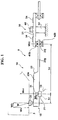
- FIG. 1 is a side view schematically illustrating the construction of a seat weight measuring apparatus according to a first embodiment of the present invention. It should be noted that the left and right directions in this figure refer to the fore and aft direction of the vehicle. Since the apparatus is substantially symmetric in the fore and aft direction, the illustration of the seat weight measuring apparatus on one side is omitted.
- Each of the seat weight measuring apparatus 9 of this embodiment comprises a connecting mechanism 15 , which connects a seat 3 (including a seat frame and a seat rail) and the seat fixing portion 13 of the vehicle body to bear the seat weight, and a transmitting mechanism 16 which transmits action of the seat weight on the connecting mechanism 15 to a load sensor 54 of a load cell 50 .
- Each connecting mechanism 15 comprises a burdening member (pin bracket) 25 , an arm (Z arm) 23 , a base pin 31 , and a base 21 .
- the burdening members 25 are arranged at four corners, front and rear on left and right sides of the seat 3 , respectively and transmit the weight of the seat including the weight of a passenger sitting thereon to the arms 23 .
- Each arm 23 is pivotable about each base pin 31 .
- the base pin 31 is connected to the seat fixing portion 13 of the vehicle body via the base 21 .
- the arm 23 has a thin plate portion 23 g extending to the right in this figure.
- the end of the thin plate portion 23 g is an action portion 23 j to the load cell 50 .
- the thin plate portion 23 g has a flexible structure (controlled flexible structure) which is relatively easily deflected.
- a portion in the arm 23 which composes in part the connecting mechanism 15 includes a rib-like wall 23 a formed to increase its stiffness and strength.
- the load cell 50 comprises the sensor plate 51 and strain gauges 54 attached on an upper surface of the sensor plate 51 .
- the load is measured by the strain gauge 54 on the sensor plate 51 .
- the right portion of the sensor plate 51 has the same structure as the left portion.
- the transmitting mechanism 16 comprises the arm 23 and the supports 41 b , 42 b . With these supports 41 b , 42 b , vertical load can be transmitted but lateral load except for a part of frictional force can not be transmitted.
- a load W of the seat 3 is transmitted from the burdening members 25 to the arms 23 .
- the load W includes a vertical component Wv and a lateral component Wh.
- the vertical component Wv includes a part of the weight of the seat 3 and the weight of the passenger.
- the loads exerted by the weight of the passenger to be transmitted from the respective burdening members 25 to the arms 23 are different according to the weight and the posture of the passenger, the acceleration of the vehicle, and the like.
- the lateral component Wh of the load W mainly depends on the acceleration of the vehicle and the force of the passenger's legs thrusting against the vehicle floor.
- a distance (span) between a position (contact portion) where the burdening member 25 acts on the arm 23 and the center line of the base pin 31 (pivot) is represented by S.
- a distance (span) between the center line of the base pin 31 and the action portion 23 j to the load cell 50 is represented by S 2 .
- the transmitting mechanism 9 of the seat weight measuring apparatus has a characteristics of selectively transmitting the vertical component as a part of the load W from the seat 3 to the load cell 50 .
- FIGS. 2 (A), 2 (B) are side views showing a second and third embodiment, respectively, of the connecting portion (action point) between the arm and the load cell.
- FIG. 2 (A) shows the second embodiment in which a pin hole 103 is formed at an end of an arm 101 and a bracket 107 of the sensor plate 51 is provided with a pin 105 so that the arm 101 and the sensor plate 51 are pivotally connected to each other.
- torsional stress due to the deflection of the arm 101 can be absorbed, thereby exhibiting an effect that only vertical force is transmitted to the sensor plate 51 .
- FIG. 2 (B) shows a third embodiment in which a curved portion 113 is formed at an end of an arm 111 and has a support 115 at its end which is connected to a bracket 117 of the sensor plate 51 .
- the curved portion 113 is particularly easily deflected, exhibiting the same effect as that obtained by the pin 105 .
- FIGS. 3 (A), 3 (B) show the general structure of the seat weight measuring apparatus according to the first embodiment of the present invention.
- FIG. 3 (A) is an exploded perspective view and
- FIG. 3 (B) is a sectional view of the pin bracket.
- FIGS. 3 (A), 3 (B), and 4 (A), 4 (B) described in the following the illustration of a rear half is omitted.
- FIGS. 4 (A) through 4 (D) show the general structure of the seat weight measuring apparatus according to the first embodiment of the present invention.
- FIG. 4 (A) is a plan view
- FIG. 4 (B) is a longitudinal sectional view
- FIGS. 4 (C) and 4 (D) are sectional views thereof,
- FIG. 5 is a partially broken perspective view showing detailed structure around the sensor plate.
- FIG. 6 (A) is a plan view showing the detailed structure of the sensor plate.
- FIGS. 7 (A) through 7 (C) are views showing the relation between the sensor plate and the half arm.
- FIG. 7 (A) is a plan view
- FIG. 7 (B) is a side view illustrating the non-loaded state
- FIG. 7 (C) is a side view schematically illustrating the loaded state.
- the seat weight measuring apparatus 9 is structured to have an elongated base 21 as its body.
- the base 21 extends long in the fore and aft direction when mounted to the vehicle body and is a product made by press-working a steel plate having a U-shaped cross section, as shown in FIGS. 4 (C), 4 (D).
- the bottom of the base 21 is referred to as a bottom plate 21 c and portions which stand from the left and right edges of the bottom plate 21 c to form corners of 90° therebetween are referred to as side plates 21 a , 21 a′.
- Each of the base side plates 21 a , 21 a ′ is provided with two pairs of pin holes 21 e and 21 g in front and rear portions, respectively.
- the pin holes 21 e , 21 g are formed to face the pin holes 21 e , 21 g of the opposite side plates 21 a , 21 a′.
- the holes 21 e near the front and rear ends of the base 21 are formed in portions away at a distance from the front and rear ends, respectively, wherein the distance corresponds to approximately 1 ⁇ 8 of the overall length of the base 21 .
- the holes 21 e are vertically elongated holes, as shown in FIG. 3 (A). Inserted tough the elongated holes 21 e are ends of bracket pins 27 . Fitted on the left and right ends of each bracket pin 27 are retainers 33 preventing the bracket pin 27 from coming off the elongated holes 21 e.
- each bracket pin 27 is transmitting the seat weight exerted on the pin bracket 25 to the Z arm 23 .
- the pin holes 21 g are formed in positions closer to the center than the positions of the elongated holes 21 e (at a distance corresponding to approximately ⁇ fraction (1/10) ⁇ of the overall length of the base 21 from the elongated hole 21 e ). Inserted into the holes 21 g are base pins 31 . Each of the base pins 31 extends to bridge the left and right side plates 21 a , 21 a ′. Fitted on the left and right ends of the pin 31 are retainers 33 , thereby fixing the base pin 31 to the base 21 .
- the base pin 31 is the pivot shaft of the Z arm 23 .
- the Z arms 23 are arranged inside of the base 21 .
- Each of the Z arms 23 has a center portion, when seen in plan view, which is forked (into two branches 23 h ) and has a rectangular portion near the end.
- the Z arm 23 has side plates 23 a formed by upwardly folding left and right edge portions thereof by 90°.
- the side plates 23 a extend from the end to the middle portion.
- the branches 32 h are only flat plates.
- the side plates 23 a extend along the inner surfaces of the side plates 21 a of the base 21 . There are clearances between the side plates 23 a and the side plates 21 a.
- Each of the Z arm side plates is provided with two pin holes 23 c , 23 e formed therein. Inserted into the pin holes 23 c formed near the end is the bracket pin 27 . The bracket pin 27 and the pin holes 23 c slide little relative to each other. Inserted into the pin holes 23 e at the center side is the base pin 31 . The base pin 31 is the pivot of the Z arm 23 , so the base pin 31 and the pin holes 23 e slide relative to each other by pivotal movement of the Z arm 23 . Sandwiched between the base side plates 21 a about the base pin 31 and the Z arm side plates 23 a are disk-like spacers 35 having holes.
- the length of the branches 23 h of the Z arm 23 corresponds substantially to a half of the overall length of the Z arm 23 .
- the branches 23 h are separated from each other in the right and left direction and extend toward the center of the base 21 .
- Each of the branches 23 h has a reduced width near the center.
- the action portions 23 j at the ends of the branches 23 h are clamped between wings 41 a , 42 a of upper and lower half arms 41 , 42 as shown in FIGS. 5 and 7 (A) through 7 (C).
- the Z arm 23 slightly pivots (the maximum pivotal angle of approximately 5°) whereby the action portions 23 j transmit the load to the sensor plate 51 through the half arms 41 , 42 .
- the pin bracket 25 is formed to have an inverted U-shaped cross section as shown in FIG. 4 (C).
- the length of the pin bracket 25 in the fore and aft direction substantially corresponds to ⁇ fraction (1/20) ⁇ of that of the base 21 .
- the pin bracket 25 has a flat upper surface 25 a on which the seat rail 7 shown in FIGS. 8 (A), 8 (B) is mounted.
- the seat rail 7 is strongly fixed to the upper surface 25 a by bolts or other fastening means.
- the pin bracket 25 hag left and right side plates 25 b downwardly projecting, of which lower ends are bent inwardly.
- the pin bracket 25 is disposed inside the Z arm 23 in such a manner as to have clearances between the side plates 25 b and the Z arm side plates 23 a .
- the side plates 25 b are provided with pin holes 25 c formed therein. Inserted into the pin holes 25 c is a bracket pin 27 .
- the inner diameter of each pin hole 25 c is larger than the diameter of the bracket pin 27 . The clearance between them absorbs dimensional tolerance of the seat and the vehicle body and/or unexpected deformation.
- a spring plate 29 Disposed between the side plates 25 b of the pin bracket 25 and the side plates 23 b of the Z arm 23 is a spring plate 29 having spring washer portions with holes.
- the pin bracket 27 is loosely inserted into the holes of the spring washer portions.
- the spring plate 29 composes a centering mechanism for biasing the pin bracket 25 toward the center.
- the centering mechanism as mentioned above makes the pin bracket 25 to be positioned as close to the center in the slidable range as possible.
- the seat rail 7 , the pin bracket 25 , the Z arm 23 , the base 21 , and the seat bracket 11 compose in combination each connecting mechanism between the seat and the vehicle body.
- FIGS. 6 (A) through 6 (C) show a structural example of the sensor plate of the seat weight measuring apparatus according to the first embodiment of the present invention.
- FIG. 6 (A) is a plan view of the sensor plate
- FIG. 6 (B) is a structural view of the section of the sensor plate for illustrating its concept
- FIG. 6 (C) is a circuit diagram of the sensor.
- an insulating layer (lower insulating layer) 52 for electrical insulation.
- a wiring layer 53 selectively formed on the insulating layer 52 is a wiring layer 53 .
- a resistant layer 54 selectively formed on the wiring layer 53 is a resistant layer 54 which composes the strain gauge 54 as a load sensor.
- an insulating layer (upper insulating layer) 55 is applied over these layers as a protective layer. In this manner, the electrical circuit including resistors is directly laminated on the spring member 51 , thereby reducing the working cost and the assembly cost and further improving the heat resistance and the corrosion resistance.
- the sensor plate 51 is a rectangular plate having two necks as a whole.
- the sensor plate 51 is provided with a central hole 51 a formed in the center thereof and bolt holes 51 b formed in end portions thereof.
- the load cell 50 is formed around the central hole 51 a and between the central hole 51 a and the bolt holes 51 b .
- V-like concavities are provided in both side edges of a region 51 c between the central hole 51 a and the bolt holes 51 b . These concavities ensure positions to be deformed of the sensor plate 51 , thereby preventing positional variation of distortion and stabilizing the sensitivity of the load cell 50 .
- the load cell 50 is substantially symmetrical about the center of the central hole 51 a .
- the load cell 50 is composed of four strain gauges 54 a , 54 b , 54 c , and 54 d . Two of them 54 a , 54 b to be applied with tensile strain are arranged near the bolt holes 51 b (near the ends), while the other two strain gauges 54 c , 54 d to be applied with compressive strain are arranged near the central hole 51 a (central side).
- the strain gauges 54 a , 54 b , 54 c , and 54 d are connected to each other by wirings 53 a , 53 b , 53 c , and 53 d to form a bridge circuit shown in FIG. 6 (C).
- Load applied on the front-side portion of the seat is measured by the two strain gauges 54 a , 54 c and load applied on the rear-side portion of the seat is measured by the two strain gauges 54 b , 54 d .
- Squares marked by numerals 1 , 2 , 3 , 4 in FIGS. 6 (A), 6 (C) are terminals.
- a sensitivity control resistor 54 e Arranged between the strain gauges 54 a , 54 c and the strain gauges 54 b , 54 d is a sensitivity control resistor 54 e.
- the load may be obtained by conversion from deflection of he sensor plate 51 detected by electrical capacitance pressure sensors or Hall elements, instead of the detection of distortion of the sensor plate 51 being detected by the strain gauges 54 a , 54 b , 54 c , and 54 d.
- the sensor plate 51 is strongly fixed to the top of a column 63 at the center of the base bottom plate 21 c.
- each of the left and right portions of the seat is one load cell 50 so that loads on the front-side portion and the rear-side portion of the seat are each measured by one load cell 50 , thereby reducing the manufacturing cost and the assembly/wiring cost.
- the half arms 41 , 42 are provided in the form of two pairs to be arranged above and below the front and rear portions of the sensor plate 51 to clamp the sensor plate 51 . Since the half arms 41 , 42 have the same configuration, a description will be made as only an upper half arm 41 .
- the half arm 41 comprises a half arm body 41 c which is a rectangular plate with an attachment hole 41 e (FIGS. 7 (B), 7 (C)) formed in the center thereof.
- the half arm 41 further comprises wings 41 a extending in the left and right directions from edges of the body 41 c near the sensor plate center, and levee-like supports 41 b formed on the backs of the wings 41 a and extending in the left and right directions.
- the top of each support 41 b is slightly edged.
- the wings 41 a , 42 a of the upper and lower half arms 41 , 42 are arranged in such a manner that the supports 41 b , 42 b face each other. Sandwiched between the supports 41 b , 42 b is the action portion 23 j of the Z arm 23 .
- the supports are positioned at the middle (the neck (the region 51 c ) of the sensor plate 51 ) of a region between the two strain gauges 54 a and 54 c or 54 d and 54 b.
- FIG. 7 (C) schematically and exaggeratedly shows the state of the sensor plate and the half arms.
- the front side strain gauges 54 a , 54 c are distorted according to the load on the front-side portion of the seat, while the strain gauges 54 b , 54 d are distorted according to the load on the rear-side portion of the seat.
- the variations in the resistances of the respective strain gauges are obtained as electrical signals whereby the one load cell measures the loads on the front-side and rear-side portions of the seat.
- the components of the load cells for measuring loads on front and rear locations on left and right sides of the seat are arranged as compact as possible, thereby reducing the number of load cells, the manufacturing cost, and also assembly/wiring cost. Even with the reduced number of the load cells, the loads on the four locations, front and rear on left and right sides can be measured, thereby detecting the center of gravity of the passenger.
- the transmitting mechanism selectively transmits vertical loads on the connecting mechanisms to the load sensors and transmits as little lateral loads as possible from the connecting mechanism to the load sensor wherein the lateral loads cause error of the load sensors, thereby measuring the weight of the passenger with higher precision.
- FIGS. 9 (A) and 9 (B) illustrate a fourth embodiment of the present invention.
- the fourth embodiment is similar to the first embodiment except that the seat weight measuring apparatus is arranged so that the long side of each of the four transmitting mechanisms 118 is perpendicular to the direction of seat rail movement (forward direction).
- a front sensor plate 51 is used to measure the vertical load at the front-right and front-left corners while a back sensor plate 54 is used to measure weight at the back-right and back-left corners.
- the load sensors 51 , 54 output signals to a seat weight sensor electronic control unit 119 .
- the seat weight electronic control unit 119 outputs signals to an airbag electronic control unit.
- FIGS. 10 (A) and 10 (B) illustrate a fifth embodiment of the present invention.
- the fifth embodiment is similar to the first embodiment except that the seat weight measuring apparatus is arranged so that the long side of transmitting mechanism 120 is directed toward the center of the seat to form an “X” shape. Thus, only a single sensor plate 123 is required.
- FIGS. 11 (A) and 11 (B) illustrate a sixth embodiment of the present invention.
- the sixth embodiment is similar to the first embodiment except that three transmitting mechanisms 121 , 121 , 131 are used to form a seat weight measuring apparatus having a “Y” shape.
- a cross-brace 122 which is part of transmitting mechanism 131 , extends between and is mounted to the connecting mechanisms at the front-right and front-left seat corners.
- transmitting mechanism 131 transmits the load on the front-right and front-left seat corners to the sensor plate 124 .
- Two transmitting mechanisms 121 are mounted to and transmit the load on the connecting mechanisms on the back-left and back-right seat corners, respectively. Thus, only a single sensor plate 124 is required.
- FIGS. 12 (A) and 12 (B) illustrate a seventh embodiment of the present invention.
- the seventh embodiment is similar to the sixth embodiment except that the seat weight measuring apparatus forms a “T” shape instead of a “Y” shape.
- Transmitting mechanism 125 forms the long portion of the “T” and comprises a cross-brace 122 (similar to the sixth embodiment).
- Two transmitting mechanisms 127 which are attached to the back-right and back-left connecting mechanisms, form the top of the “T”.
- a single sensor plate 126 is required.
- FIGS. 13 (A) and 13 (B) illustrate an eighth embodiment of the present invention.
- the eighth embodiment is similar to the first embodiment except as explained below.
- a single transmitting mechanism 128 transmits the load on the connecting mechanisms of both the back-right and back-left seat corners to the sensor plate 130 .
- Cross-brace 134 of transmitting mechanism 128 is connected to the connecting mechanisms at the back-right and back-left seat corners.
- a single transmitting mechanism 129 transmits the load on the connecting mechanisms of the front-right and front-left seat corners to the sensor plate 130 .
- Cross-brace 134 of transmitting mechanism 129 is connected to the connecting mechanisms at the front-right and front-left seat corners
- the two transmitting mechanisms are arranged between and are substantially parallel to the seat rails, forming an “I” shape.
- a single sensor plate 130 is required.
- FIG. 14 is a front view showing the connection of cross-brace 122 of the transmitting mechanisms of any of the sixth and seventh embodiments. This drawing also applies analogously to cross-brace 134 of the eighth embodiment.
- Cross-brace 122 is held between upper bracket 133 and lower bracket 132 .
- Upper bracket 133 is attached to seat frame 5 .
- Seat frame 5 is attached to seat pan 136 .
- Reinforcement 135 is provided for lower bracket 132 .
Abstract
Description
Claims (20)
Applications Claiming Priority (2)
| Application Number | Priority Date | Filing Date | Title |
|---|---|---|---|
| JPH11-061339 | 1999-03-09 | ||
| JP06133999A JP4585054B2 (en) | 1999-03-09 | 1999-03-09 | Seat weight measuring device |
Publications (1)
| Publication Number | Publication Date |
|---|---|
| US6323444B1 true US6323444B1 (en) | 2001-11-27 |
Family
ID=13168286
Family Applications (1)
| Application Number | Title | Priority Date | Filing Date |
|---|---|---|---|
| US09/521,881 Expired - Lifetime US6323444B1 (en) | 1999-03-09 | 2000-03-09 | Seat weight measuring apparatus |
Country Status (4)
| Country | Link |
|---|---|
| US (1) | US6323444B1 (en) |
| JP (1) | JP4585054B2 (en) |
| DE (2) | DE10011372B4 (en) |
| GB (1) | GB2349474B (en) |
Cited By (68)
| Publication number | Priority date | Publication date | Assignee | Title |
|---|---|---|---|---|
| US6401855B1 (en) * | 2000-07-13 | 2002-06-11 | Trw Inc. | Seat load sensing apparatus |
| US6448512B1 (en) * | 2000-08-22 | 2002-09-10 | Trw Inc. | Weight sensing apparatus |
| US20020175490A1 (en) * | 2001-05-08 | 2002-11-28 | Morio Sakai | Occupant judging apparatus |
| US6502887B1 (en) * | 2001-06-29 | 2003-01-07 | Daimlerchrysler Corporation | Arrangement for mounting a restraint belt mounted vehicle seat to a vehicle floor |
| US20030071491A1 (en) * | 2001-06-13 | 2003-04-17 | Kavlico Corporation | Seat weight measurement system |
| US20030083795A1 (en) * | 2001-10-31 | 2003-05-01 | Automotive Systems Laboratory, Inc. | Occupant detection system |
| US6559392B1 (en) * | 2001-10-12 | 2003-05-06 | Lear Corporation | Weight-sensing support assembly for automotive seat cushion frame |
| US6561300B1 (en) * | 1999-11-30 | 2003-05-13 | Aisin Seiki Kabushiki Kaisha | Vehicle seat having passenger detector |
| US6571456B2 (en) * | 1999-07-12 | 2003-06-03 | Gagetek Technologies Holdings Company | Method for making torsional sensing load cells |
| US6571647B1 (en) * | 1999-03-09 | 2003-06-03 | Takata Corporation | Seat weight measuring apparatus |
| US6577023B1 (en) | 1998-12-30 | 2003-06-10 | Automotive Systems Laboratory, Inc. | Occupant detection system |
| US20030106723A1 (en) * | 2001-12-07 | 2003-06-12 | Rajeev Thakur | Weight sensors having centralized loose tolerance universal force and Mx/My moments overload stops |
| US20030111276A1 (en) * | 2001-12-13 | 2003-06-19 | Takata Corporation | Seat weight measuring apparatus |
| FR2834063A1 (en) * | 2001-12-21 | 2003-06-27 | Sartorius Gmbh | WEIGHT MEASURING DEVICE ACTING ON A VEHICLE SEAT AND FITTING THE SEAT THEREFOR |
| EP1336539A1 (en) * | 2002-02-18 | 2003-08-20 | Mazda Motor Corporation | seat belt system for vehicles and vehicle provided therewith |
| US6617531B1 (en) * | 1999-09-21 | 2003-09-09 | Takata Corporation | Seat load measuring device |
| US6672176B2 (en) | 1999-07-12 | 2004-01-06 | Gagetek Technologies Holdings Company | Torsional sensing load cell |
| EP1391706A1 (en) * | 2002-08-21 | 2004-02-25 | Takata Corporation | Seat load measuring apparatus |
| US20040040390A1 (en) * | 2002-08-30 | 2004-03-04 | Honda Giken Kogyo Kabushiki Kaisha | Occupant detection system |
| US20040075568A1 (en) * | 2002-10-02 | 2004-04-22 | Takatoshi Tanabe | Passenger detector and method of adjusting the same |
| US20040094337A1 (en) * | 2001-04-16 | 2004-05-20 | Kiyoshi Saito | Weight measuring equipment and crew weight measuring equipment comprising it |
| US20040130176A1 (en) * | 2003-01-03 | 2004-07-08 | Lear Corporation | Seat position sensing device for use in occupant restraint |
| US20040140137A1 (en) * | 2001-05-01 | 2004-07-22 | Bizerba Gmbh & Co. Kg | Vehicle seat |
| US6825765B2 (en) | 1998-12-30 | 2004-11-30 | Automotive Systems Laboratory, Inc. | Occupant detection system |
| US20040262050A1 (en) * | 2003-06-27 | 2004-12-30 | Takata Corporation | Seat weighing system |
| US20040262960A1 (en) * | 2003-06-26 | 2004-12-30 | Young Oliver J. | Vehicle occupant sensing system having sensors with formed terminals |
| US20040262962A1 (en) * | 2003-06-26 | 2004-12-30 | Young Oliver J. | Vehicle occupant sensing system having discrete wiring |
| US20040262978A1 (en) * | 2003-06-26 | 2004-12-30 | Young Oliver J. | Vehicle occupant sensing system having sensor assemblies with variable biasing member |
| US20040262049A1 (en) * | 2003-06-27 | 2004-12-30 | Takata Corporation | Seat weight measuring device |
| US20040262956A1 (en) * | 2003-06-27 | 2004-12-30 | Takata Corporation | Seat weighing device |
| US20050001731A1 (en) * | 2003-06-27 | 2005-01-06 | Takata Corporation | Seat weighing device |
| US20050006151A1 (en) * | 2003-07-09 | 2005-01-13 | Cherry Corporation | Seat for sensing a load |
| US20050029843A1 (en) * | 2003-06-26 | 2005-02-10 | Young Oliver J. | Vehicle occupant sensing system having an upper slide member with an emitter interference member |
| US6859753B1 (en) | 2003-08-26 | 2005-02-22 | Robert Bosch Corporation | Apparatus and method for measuring the weight of an occupant in a vehicle |
| US20050066748A1 (en) * | 2003-09-30 | 2005-03-31 | Takata Corporation | Seat weight measuring apparatus |
| US20050093277A1 (en) * | 2003-11-04 | 2005-05-05 | Delphi Technologies, Inc. | Deflection plate weight sensor for vehicle seat |
| US6901322B1 (en) | 2003-12-30 | 2005-05-31 | Lear Corporation | Method of predicting an empty seat condition in an occupancy sensing system |
| US20050138784A1 (en) * | 2003-12-30 | 2005-06-30 | Nathan John F. | Method of testing a sensor array incorporated into a vehicle seat |
| US20050140358A1 (en) * | 2003-12-30 | 2005-06-30 | Kennedy Karl R. | Method of determining an equivalent value for a failed sensor in a vehicle seat having an occupancy sensing system |
| US20050149284A1 (en) * | 2003-12-30 | 2005-07-07 | Nathan John F. | Method of tuning a sensor array for occupancy sensing in a vehicle seat |
| US20050149461A1 (en) * | 2003-12-30 | 2005-07-07 | Karl Kennedy | Method of occupancy classification in a vehicle seat |
| US20050151355A1 (en) * | 2004-01-14 | 2005-07-14 | Samuel Hanlon | Vehicle seat assembly having a field effect sensor for detecting seat position |
| US20050167166A1 (en) * | 2004-01-29 | 2005-08-04 | Vogel Mark S. | Occupant classification sense element |
| US20050242554A1 (en) * | 2004-04-28 | 2005-11-03 | Takata Corporation | Seat load measuring device and occupant protection system using the same |
| US20060004518A1 (en) * | 2004-07-02 | 2006-01-05 | Sleboda Pawel W | Vehicle occupant sensing system for a vehicle seat assembly and method of operating the same |
| WO2006029348A1 (en) * | 2004-09-08 | 2006-03-16 | Tk Holdings Inc. | Seat weight sensor |
| US20060086595A1 (en) * | 2004-10-27 | 2006-04-27 | Sallam Faisal K | Vehicle occupant sensing system having a contamination barrier member |
| US20060091657A1 (en) * | 2004-10-27 | 2006-05-04 | Sallam Faisal K | Vehicle occupant sensing system having enclosed sensor assembly |
| US20060091655A1 (en) * | 2004-10-27 | 2006-05-04 | Sallam Faisal K | Vehicle occupant sensing system having guiding ribs |
| US20060091656A1 (en) * | 2004-10-27 | 2006-05-04 | Sallam Faisal K | Vehicle occupant sensing system having a retention member for a biasing member |
| US20060097497A1 (en) * | 2004-10-27 | 2006-05-11 | Sallam Faisal K | Vehicle occupant sensing system having a contamination barrier member |
| US7063382B2 (en) | 2003-06-26 | 2006-06-20 | Lear Corporation | Vehicle seat assembly having a vehicle occupant sensing system and a seat cushion insert |
| US20060180359A1 (en) * | 2005-02-14 | 2006-08-17 | Trw Automotive U.S. Llc | Seat load sensing apparatus |
| US20060181119A1 (en) * | 2005-02-14 | 2006-08-17 | Trw Automotive U.S. Llc | Seat load sensing apparatus |
| US20060192416A1 (en) * | 2005-02-10 | 2006-08-31 | Trw Automotive U.S. Llc | Seat load sensing apparatus |
| US7100980B2 (en) | 2004-10-27 | 2006-09-05 | Lear Corporation | Vehicle seat assembly having a vehicle occupant sensing system with a biasing pad |
| US20070012502A1 (en) * | 2005-05-04 | 2007-01-18 | Daimlerchrysler Ag | Method for operating and electrically adjustable vehicle seat |
| US7172244B2 (en) | 2003-06-26 | 2007-02-06 | Lear Corporation | Vehicle seat assembly having a vehicle occupant sensing system and a seat cushion insert positioned therein |
| US20070057527A1 (en) * | 2005-09-12 | 2007-03-15 | Ts Tech Co., Ltd. | Passenger's weight measurement device for vehicle seat and attachment structure for load sensor |
| US20090179764A1 (en) * | 2008-01-15 | 2009-07-16 | Chul-Sub Lee | Device For Detecting Passenger's Weight In Vehicle |
| US20090217530A1 (en) * | 2005-12-02 | 2009-09-03 | Ferrari S.P.A. | Method for mounting a seat provided with weight sensors on a motorcar frame |
| US20110043009A1 (en) * | 2009-08-24 | 2011-02-24 | Aisin Seiki Kabushiki Kaisha | Apparatus and method for determining impact on vehicle and apparatus for warning impact on vehicle |
| US20110186358A1 (en) * | 2008-09-04 | 2011-08-04 | Eisenmann Ag | Weighing Device |
| US20120012405A1 (en) * | 2010-07-19 | 2012-01-19 | Robert Bosch Gmbh | Occupant weight sensing using intelligent fastener and vertical load transmitting brackets |
| CN105222874A (en) * | 2015-11-18 | 2016-01-06 | 湖南城市学院 | A kind of high life electronic scales |
| US10654435B2 (en) * | 2017-02-22 | 2020-05-19 | Bgm Engineering, Inc. | Sensor module for use in low-cost weight measurement and sensing system |
| US11565626B2 (en) | 2020-12-31 | 2023-01-31 | Joyson Safety Systems Acquisitions LLC | Systems and methods for child presence detection with driver warning alerts and bypass option |
| US11719557B2 (en) | 2019-12-24 | 2023-08-08 | Joyson Safety Systems Acquisition Llc | Apparatus and method of producing a sensing substrate |
Families Citing this family (4)
| Publication number | Priority date | Publication date | Assignee | Title |
|---|---|---|---|---|
| JP3694450B2 (en) * | 2000-09-18 | 2005-09-14 | アルプス電気株式会社 | Load sensor |
| DE10121668A1 (en) * | 2001-05-04 | 2002-11-07 | Bayerische Motoren Werke Ag | Measurement arrangement for determining motor vehicle seat occupation, in which the seat in mounted on a support body with elastic deformation arms and attached strain gauges |
| DE10335255A1 (en) * | 2003-08-01 | 2005-03-03 | Daimlerchrysler Ag | Safety device e.g. for lengthwise movable vehicle seat, has pressure sensor arranged in the region of the vehicle chassis |
| JP2007292742A (en) * | 2006-03-29 | 2007-11-08 | Alps Electric Co Ltd | Load sensor |
Citations (16)
| Publication number | Priority date | Publication date | Assignee | Title |
|---|---|---|---|---|
| US3835946A (en) * | 1972-09-29 | 1974-09-17 | Mettler Instrumente Ag | Platform scale |
| US4258810A (en) * | 1979-05-25 | 1981-03-31 | Masstron Scale, Inc. | Weighing apparatus |
| US4297875A (en) * | 1979-04-18 | 1981-11-03 | Bizerba-Werke Wilhelm Kraut Kg | Apparatus for introducing a force to be measured into a bending rod |
| US4411327A (en) * | 1981-05-14 | 1983-10-25 | Hottinger Baldwin Measurements, Inc. | Apparatus for applying a load to a strain gage transducer beam |
| US4880069A (en) * | 1988-08-30 | 1989-11-14 | Weigh-Tronix, Inc. | Electronic bathroom scale |
| US5573269A (en) * | 1993-12-02 | 1996-11-12 | Trw Vehicle Safety Systems Inc. | Apparatus and method for sensing and restraining an occupant of a vehicle seat |
| US5600104A (en) * | 1993-10-20 | 1997-02-04 | Structural Instrumentation, Inc. | Load cell having reduced sensitivity to non-symmetrical beam loading |
| JPH09156666A (en) | 1995-12-07 | 1997-06-17 | Dainippon Printing Co Ltd | Combination body of package and containing box |
| US5739757A (en) * | 1997-01-30 | 1998-04-14 | Breed Automotive Technology, Inc. | Vehicle passenger weight sensor |
| JPH10121627A (en) | 1996-10-16 | 1998-05-12 | Sankyo Alum Ind Co Ltd | Joint member |
| GB2333070A (en) | 1998-01-12 | 1999-07-14 | Autoliv Dev | Control of vehicle airbag inflation |
| EP0950560A2 (en) | 1998-04-16 | 1999-10-20 | Takata Corporation | A seat weight measuring apparatus |
| GB2337027A (en) | 1998-05-05 | 1999-11-10 | Delco Electronic Europ Gmbh | Load sensing mounting for a vehicle seat |
| US5998742A (en) * | 1996-08-26 | 1999-12-07 | Eveready Battery Company, Inc. | High speed high accuracy active force transducer |
| US6039344A (en) | 1998-01-09 | 2000-03-21 | Trw Inc. | Vehicle occupant weight sensor apparatus |
| US6087598A (en) * | 1999-02-03 | 2000-07-11 | Trw Inc. | Weight sensing apparatus for vehicle seat |
-
1999
- 1999-03-09 JP JP06133999A patent/JP4585054B2/en not_active Expired - Fee Related
-
2000
- 2000-03-09 US US09/521,881 patent/US6323444B1/en not_active Expired - Lifetime
- 2000-03-09 DE DE10011372A patent/DE10011372B4/en not_active Expired - Fee Related
- 2000-03-09 DE DE20004392U patent/DE20004392U1/en not_active Expired - Lifetime
- 2000-03-09 GB GB0005616A patent/GB2349474B/en not_active Expired - Fee Related
Patent Citations (17)
| Publication number | Priority date | Publication date | Assignee | Title |
|---|---|---|---|---|
| US3835946A (en) * | 1972-09-29 | 1974-09-17 | Mettler Instrumente Ag | Platform scale |
| US4297875A (en) * | 1979-04-18 | 1981-11-03 | Bizerba-Werke Wilhelm Kraut Kg | Apparatus for introducing a force to be measured into a bending rod |
| US4258810A (en) * | 1979-05-25 | 1981-03-31 | Masstron Scale, Inc. | Weighing apparatus |
| US4411327A (en) * | 1981-05-14 | 1983-10-25 | Hottinger Baldwin Measurements, Inc. | Apparatus for applying a load to a strain gage transducer beam |
| US4880069A (en) * | 1988-08-30 | 1989-11-14 | Weigh-Tronix, Inc. | Electronic bathroom scale |
| US5600104A (en) * | 1993-10-20 | 1997-02-04 | Structural Instrumentation, Inc. | Load cell having reduced sensitivity to non-symmetrical beam loading |
| US5573269A (en) * | 1993-12-02 | 1996-11-12 | Trw Vehicle Safety Systems Inc. | Apparatus and method for sensing and restraining an occupant of a vehicle seat |
| JPH09156666A (en) | 1995-12-07 | 1997-06-17 | Dainippon Printing Co Ltd | Combination body of package and containing box |
| US5998742A (en) * | 1996-08-26 | 1999-12-07 | Eveready Battery Company, Inc. | High speed high accuracy active force transducer |
| JPH10121627A (en) | 1996-10-16 | 1998-05-12 | Sankyo Alum Ind Co Ltd | Joint member |
| US5739757A (en) * | 1997-01-30 | 1998-04-14 | Breed Automotive Technology, Inc. | Vehicle passenger weight sensor |
| US6039344A (en) | 1998-01-09 | 2000-03-21 | Trw Inc. | Vehicle occupant weight sensor apparatus |
| GB2333070A (en) | 1998-01-12 | 1999-07-14 | Autoliv Dev | Control of vehicle airbag inflation |
| EP0950560A2 (en) | 1998-04-16 | 1999-10-20 | Takata Corporation | A seat weight measuring apparatus |
| US6069325A (en) * | 1998-04-16 | 2000-05-30 | Takata Corporation | Seat weight measuring apparatus |
| GB2337027A (en) | 1998-05-05 | 1999-11-10 | Delco Electronic Europ Gmbh | Load sensing mounting for a vehicle seat |
| US6087598A (en) * | 1999-02-03 | 2000-07-11 | Trw Inc. | Weight sensing apparatus for vehicle seat |
Cited By (131)
| Publication number | Priority date | Publication date | Assignee | Title |
|---|---|---|---|---|
| US6825765B2 (en) | 1998-12-30 | 2004-11-30 | Automotive Systems Laboratory, Inc. | Occupant detection system |
| US6577023B1 (en) | 1998-12-30 | 2003-06-10 | Automotive Systems Laboratory, Inc. | Occupant detection system |
| US6571647B1 (en) * | 1999-03-09 | 2003-06-03 | Takata Corporation | Seat weight measuring apparatus |
| US6672176B2 (en) | 1999-07-12 | 2004-01-06 | Gagetek Technologies Holdings Company | Torsional sensing load cell |
| US6571456B2 (en) * | 1999-07-12 | 2003-06-03 | Gagetek Technologies Holdings Company | Method for making torsional sensing load cells |
| US6617531B1 (en) * | 1999-09-21 | 2003-09-09 | Takata Corporation | Seat load measuring device |
| US6561300B1 (en) * | 1999-11-30 | 2003-05-13 | Aisin Seiki Kabushiki Kaisha | Vehicle seat having passenger detector |
| US6401855B1 (en) * | 2000-07-13 | 2002-06-11 | Trw Inc. | Seat load sensing apparatus |
| US6448512B1 (en) * | 2000-08-22 | 2002-09-10 | Trw Inc. | Weight sensing apparatus |
| US6916998B2 (en) | 2001-04-16 | 2005-07-12 | Matsushita Electric Industrial Co., Ltd. | Weight measuring device and person weight measuring equipment including the weight measuring device |
| US20040094337A1 (en) * | 2001-04-16 | 2004-05-20 | Kiyoshi Saito | Weight measuring equipment and crew weight measuring equipment comprising it |
| US6903280B2 (en) * | 2001-05-01 | 2005-06-07 | Bizerba Gbmh & Co. Kg | Vehicle seat |
| US20040140137A1 (en) * | 2001-05-01 | 2004-07-22 | Bizerba Gmbh & Co. Kg | Vehicle seat |
| US20020175490A1 (en) * | 2001-05-08 | 2002-11-28 | Morio Sakai | Occupant judging apparatus |
| US6810984B2 (en) * | 2001-05-08 | 2004-11-02 | Aisin Seiki Kabushiki Kaisha | Occupant judging apparatus |
| US6849807B2 (en) * | 2001-06-13 | 2005-02-01 | Kavlico Corporation | Seat weight measurement system |
| US20050151046A1 (en) * | 2001-06-13 | 2005-07-14 | Kavlico Corporation | Seat weight measurement system |
| US7513475B2 (en) * | 2001-06-13 | 2009-04-07 | Kavlico Corporation | Weight transfer link |
| US20030071491A1 (en) * | 2001-06-13 | 2003-04-17 | Kavlico Corporation | Seat weight measurement system |
| US6502887B1 (en) * | 2001-06-29 | 2003-01-07 | Daimlerchrysler Corporation | Arrangement for mounting a restraint belt mounted vehicle seat to a vehicle floor |
| US6559392B1 (en) * | 2001-10-12 | 2003-05-06 | Lear Corporation | Weight-sensing support assembly for automotive seat cushion frame |
| US20030083795A1 (en) * | 2001-10-31 | 2003-05-01 | Automotive Systems Laboratory, Inc. | Occupant detection system |
| US20030106723A1 (en) * | 2001-12-07 | 2003-06-12 | Rajeev Thakur | Weight sensors having centralized loose tolerance universal force and Mx/My moments overload stops |
| US6916997B2 (en) * | 2001-12-07 | 2005-07-12 | Robert Bosch Corporation | Weight sensors having centralized loose tolerance universal force and Mx/My moments overload stops |
| US6841741B2 (en) | 2001-12-13 | 2005-01-11 | Takata Corporation | Seat weight measuring apparatus |
| US20030111276A1 (en) * | 2001-12-13 | 2003-06-19 | Takata Corporation | Seat weight measuring apparatus |
| EP1319549A3 (en) * | 2001-12-13 | 2004-05-19 | Takata Corporation | A seat weight measuring apparatus |
| FR2834063A1 (en) * | 2001-12-21 | 2003-06-27 | Sartorius Gmbh | WEIGHT MEASURING DEVICE ACTING ON A VEHICLE SEAT AND FITTING THE SEAT THEREFOR |
| US20030178835A1 (en) * | 2002-02-18 | 2003-09-25 | Mazda Motor Corporation | Seat belt system for vehicles |
| US6824167B2 (en) | 2002-02-18 | 2004-11-30 | Mazda Motor Corporation | Seat belt system for vehicles |
| EP1336539A1 (en) * | 2002-02-18 | 2003-08-20 | Mazda Motor Corporation | seat belt system for vehicles and vehicle provided therewith |
| US7399932B2 (en) | 2002-08-21 | 2008-07-15 | Takata Corporation | Seat load measuring apparatus |
| US20070209451A1 (en) * | 2002-08-21 | 2007-09-13 | Takata Corporation | Seat load measuring apparatus |
| US20040035224A1 (en) * | 2002-08-21 | 2004-02-26 | Takata Corporation | Seat load measuring apparatus |
| EP1391706A1 (en) * | 2002-08-21 | 2004-02-25 | Takata Corporation | Seat load measuring apparatus |
| US6928889B2 (en) * | 2002-08-30 | 2005-08-16 | Honda Giken Kogyo Kabushiki Kaisha | Occupant detection system |
| US20040040390A1 (en) * | 2002-08-30 | 2004-03-04 | Honda Giken Kogyo Kabushiki Kaisha | Occupant detection system |
| US6957168B2 (en) | 2002-10-02 | 2005-10-18 | Denso Corporation | Passenger detector and method of adjusting the same |
| US20040075568A1 (en) * | 2002-10-02 | 2004-04-22 | Takatoshi Tanabe | Passenger detector and method of adjusting the same |
| US6854782B2 (en) * | 2003-01-03 | 2005-02-15 | Lear Corporation | Seat position sensing device for use in occupant restraint |
| DE10357991B4 (en) * | 2003-01-03 | 2006-05-24 | Lear Corp., Southfield | A seat position detecting device for use in an occupant restraint system |
| US20040130176A1 (en) * | 2003-01-03 | 2004-07-08 | Lear Corporation | Seat position sensing device for use in occupant restraint |
| US7258398B2 (en) | 2003-06-26 | 2007-08-21 | Lear Corporation | Vehicle occupant sensing system having an upper slide member with an emitter interference member |
| US7128370B2 (en) | 2003-06-26 | 2006-10-31 | Lear Corporation | Vehicle seat assembly having a vehicle occupant sensing system and reinforcing inserts positioned therein |
| US7049974B2 (en) | 2003-06-26 | 2006-05-23 | Lear Corporation | Vehicle occupant sensing system having sensors with formed terminals |
| US7063382B2 (en) | 2003-06-26 | 2006-06-20 | Lear Corporation | Vehicle seat assembly having a vehicle occupant sensing system and a seat cushion insert |
| US7034709B2 (en) | 2003-06-26 | 2006-04-25 | Lear Corporation | Vehicle occupant sensing system and method of electrically attaching a sensor to an electrical circuit |
| US7021707B2 (en) | 2003-06-26 | 2006-04-04 | Lear Corporation | Vehicle occupant sensing system having a low profile sensor assembly |
| US7075450B2 (en) | 2003-06-26 | 2006-07-11 | Lear Corporation | Vehicle occupant sensing system having discrete wiring |
| US20050029843A1 (en) * | 2003-06-26 | 2005-02-10 | Young Oliver J. | Vehicle occupant sensing system having an upper slide member with an emitter interference member |
| US7446668B2 (en) | 2003-06-26 | 2008-11-04 | Lear Corporation | Vehicle occupant sensing system having a low profile sensor assembly |
| US6994397B2 (en) | 2003-06-26 | 2006-02-07 | Lear Corporation | Vehicle occupant sensing system having sensor assemblies with variable blasing member |
| US7292027B2 (en) | 2003-06-26 | 2007-11-06 | Lear Corporation | Vehicle occupant sensing system having sensor assemblies with variable biasing member |
| US20040262960A1 (en) * | 2003-06-26 | 2004-12-30 | Young Oliver J. | Vehicle occupant sensing system having sensors with formed terminals |
| US20040263344A1 (en) * | 2003-06-26 | 2004-12-30 | Oliver Young | Vehicle occupant sensing system having a low profile sensor assembly |
| US20040262978A1 (en) * | 2003-06-26 | 2004-12-30 | Young Oliver J. | Vehicle occupant sensing system having sensor assemblies with variable biasing member |
| US6975239B2 (en) | 2003-06-26 | 2005-12-13 | Lear Corporation | Vehicle occupant sensing system having circuit carrier tray |
| US20040262958A1 (en) * | 2003-06-26 | 2004-12-30 | Oliver Young | Vehicle occupant sensing system and method of electrically attaching a sensor to an electrical circuit |
| US7172244B2 (en) | 2003-06-26 | 2007-02-06 | Lear Corporation | Vehicle seat assembly having a vehicle occupant sensing system and a seat cushion insert positioned therein |
| US20040262961A1 (en) * | 2003-06-26 | 2004-12-30 | Oliver Young | Vehicle occupant sensing system having circuit carrier tray |
| US20050218886A1 (en) * | 2003-06-26 | 2005-10-06 | Young Oliver J | Vehicle occupant sensing system having sensor assemblies with variable biasing member |
| US20040262962A1 (en) * | 2003-06-26 | 2004-12-30 | Young Oliver J. | Vehicle occupant sensing system having discrete wiring |
| US7016804B2 (en) * | 2003-06-27 | 2006-03-21 | Takata Corporation | Seat weighing device |
| US7061389B2 (en) | 2003-06-27 | 2006-06-13 | Takata Corporation | Seat weighing device |
| US20040262049A1 (en) * | 2003-06-27 | 2004-12-30 | Takata Corporation | Seat weight measuring device |
| US20040262956A1 (en) * | 2003-06-27 | 2004-12-30 | Takata Corporation | Seat weighing device |
| US20050001731A1 (en) * | 2003-06-27 | 2005-01-06 | Takata Corporation | Seat weighing device |
| US20040262050A1 (en) * | 2003-06-27 | 2004-12-30 | Takata Corporation | Seat weighing system |
| US7043997B2 (en) | 2003-07-09 | 2006-05-16 | Cherry Corporation | Seat for sensing a load |
| US20050006151A1 (en) * | 2003-07-09 | 2005-01-13 | Cherry Corporation | Seat for sensing a load |
| US6859753B1 (en) | 2003-08-26 | 2005-02-22 | Robert Bosch Corporation | Apparatus and method for measuring the weight of an occupant in a vehicle |
| US20050049824A1 (en) * | 2003-08-26 | 2005-03-03 | Robert Bosch Corporation | Apparatus and method for measuring the weight of an occupant in a vehicle |
| US7237442B2 (en) | 2003-09-30 | 2007-07-03 | Takata Corporation | Seat weight measuring apparatus |
| US20050066748A1 (en) * | 2003-09-30 | 2005-03-31 | Takata Corporation | Seat weight measuring apparatus |
| US20050093277A1 (en) * | 2003-11-04 | 2005-05-05 | Delphi Technologies, Inc. | Deflection plate weight sensor for vehicle seat |
| US7143658B2 (en) * | 2003-11-04 | 2006-12-05 | Delphi Technologies, Inc. | Deflection plate weight sensor for vehicle seat |
| US6985077B2 (en) | 2003-12-30 | 2006-01-10 | Lear Corporation | Method of tuning a sensor array for occupancy sensing in a vehicle seat |
| US7059029B2 (en) | 2003-12-30 | 2006-06-13 | Lear Corporation | Method of testing a sensor array incorporated into a vehicle seat |
| US6901322B1 (en) | 2003-12-30 | 2005-05-31 | Lear Corporation | Method of predicting an empty seat condition in an occupancy sensing system |
| US20050138784A1 (en) * | 2003-12-30 | 2005-06-30 | Nathan John F. | Method of testing a sensor array incorporated into a vehicle seat |
| US20050140358A1 (en) * | 2003-12-30 | 2005-06-30 | Kennedy Karl R. | Method of determining an equivalent value for a failed sensor in a vehicle seat having an occupancy sensing system |
| US7053759B2 (en) | 2003-12-30 | 2006-05-30 | Lear Corporation | Method of determining an equivalent value for a failed sensor in a vehicle seat having an occupancy sensing system |
| US20050149284A1 (en) * | 2003-12-30 | 2005-07-07 | Nathan John F. | Method of tuning a sensor array for occupancy sensing in a vehicle seat |
| US20050149461A1 (en) * | 2003-12-30 | 2005-07-07 | Karl Kennedy | Method of occupancy classification in a vehicle seat |
| US7034670B2 (en) | 2003-12-30 | 2006-04-25 | Lear Corporation | Method of occupancy classification in a vehicle seat |
| US20050151355A1 (en) * | 2004-01-14 | 2005-07-14 | Samuel Hanlon | Vehicle seat assembly having a field effect sensor for detecting seat position |
| US7185916B2 (en) | 2004-01-14 | 2007-03-06 | Lear Corporation | Vehicle seat assembly having a field effect sensor for detecting seat position |
| US20050167166A1 (en) * | 2004-01-29 | 2005-08-04 | Vogel Mark S. | Occupant classification sense element |
| US20050242554A1 (en) * | 2004-04-28 | 2005-11-03 | Takata Corporation | Seat load measuring device and occupant protection system using the same |
| US20060004518A1 (en) * | 2004-07-02 | 2006-01-05 | Sleboda Pawel W | Vehicle occupant sensing system for a vehicle seat assembly and method of operating the same |
| US7225067B2 (en) | 2004-07-02 | 2007-05-29 | Lear Corporation | Vehicle occupant sensing system for a vehicle seat assembly and method of operating the same |
| WO2006029348A1 (en) * | 2004-09-08 | 2006-03-16 | Tk Holdings Inc. | Seat weight sensor |
| GB2433124A (en) * | 2004-09-08 | 2007-06-13 | Tk Holdings Inc | Seat weight sensor |
| US20060061159A1 (en) * | 2004-09-08 | 2006-03-23 | Automotive Systems Laboratory, Inc. | Seat weight sensor |
| US7246850B2 (en) | 2004-09-08 | 2007-07-24 | Tk Holdings Inc. | Seat weight sensor |
| US20060091656A1 (en) * | 2004-10-27 | 2006-05-04 | Sallam Faisal K | Vehicle occupant sensing system having a retention member for a biasing member |
| US7518073B2 (en) | 2004-10-27 | 2009-04-14 | Lear Corporation | Vehicle occupant sensing system having enclosed sensor assembly |
| US20060091655A1 (en) * | 2004-10-27 | 2006-05-04 | Sallam Faisal K | Vehicle occupant sensing system having guiding ribs |
| US7100980B2 (en) | 2004-10-27 | 2006-09-05 | Lear Corporation | Vehicle seat assembly having a vehicle occupant sensing system with a biasing pad |
| US7402769B2 (en) | 2004-10-27 | 2008-07-22 | Lear Corporation | Vehicle occupant sensing system having a retention member for a biasing member |
| US7428942B2 (en) | 2004-10-27 | 2008-09-30 | Lear Corporation | Vehicle occupant sensing system having guiding ribs |
| US7405370B2 (en) | 2004-10-27 | 2008-07-29 | Lear Corporation | Vehicle occupant sensing system having enclosed sensor assembly |
| US20060097497A1 (en) * | 2004-10-27 | 2006-05-11 | Sallam Faisal K | Vehicle occupant sensing system having a contamination barrier member |
| US20060086595A1 (en) * | 2004-10-27 | 2006-04-27 | Sallam Faisal K | Vehicle occupant sensing system having a contamination barrier member |
| US20070267282A1 (en) * | 2004-10-27 | 2007-11-22 | Lear Corporation | Vehicle occupant sensing system having enclosed sensor assembly |
| US7365278B2 (en) | 2004-10-27 | 2008-04-29 | Lear Corporation | Vehicle occupant sensing system having a contamination barrier member |
| US20060091657A1 (en) * | 2004-10-27 | 2006-05-04 | Sallam Faisal K | Vehicle occupant sensing system having enclosed sensor assembly |
| US20060192416A1 (en) * | 2005-02-10 | 2006-08-31 | Trw Automotive U.S. Llc | Seat load sensing apparatus |
| US7219760B2 (en) | 2005-02-14 | 2007-05-22 | Trw Automotive U.S Llc | Seat load sensing apparatus |
| US20060180359A1 (en) * | 2005-02-14 | 2006-08-17 | Trw Automotive U.S. Llc | Seat load sensing apparatus |
| US20060181119A1 (en) * | 2005-02-14 | 2006-08-17 | Trw Automotive U.S. Llc | Seat load sensing apparatus |
| US7178870B2 (en) | 2005-02-14 | 2007-02-20 | Trw Automotive U.S. Llc | Seat load sensing apparatus |
| US7424355B2 (en) | 2005-05-04 | 2008-09-09 | Daimlerchrysler Ag | Method for operating and electrically adjustable vehicle seat |
| US20070012502A1 (en) * | 2005-05-04 | 2007-01-18 | Daimlerchrysler Ag | Method for operating and electrically adjustable vehicle seat |
| US8292346B2 (en) | 2005-09-12 | 2012-10-23 | Ts Tech Co., Ltd. | Passenger's weight measurement device for vehicle seat and attachment structure for load sensor |
| US20090079239A1 (en) * | 2005-09-12 | 2009-03-26 | Ts Tech Co., Ltd. | Passenger's weight measurement device for vehicle seat and attachment structure for load sensor |
| US20070057527A1 (en) * | 2005-09-12 | 2007-03-15 | Ts Tech Co., Ltd. | Passenger's weight measurement device for vehicle seat and attachment structure for load sensor |
| US7823951B2 (en) | 2005-09-12 | 2010-11-02 | Ts Tech Co., Ltd. | Passenger's weight measurement device for vehicle seat and attachment structure for load sensor |
| US20110018301A1 (en) * | 2005-09-12 | 2011-01-27 | Honda Motor Co., Ltd. | Passenger's weight measurement device for vehicle seat and attachment structure for load sensor |
| US7455343B2 (en) * | 2005-09-12 | 2008-11-25 | Ts Tech Co., Ltd. | Passenger's weight measurement device for vehicle seat and attachment structure for load sensor |
| US20090217530A1 (en) * | 2005-12-02 | 2009-09-03 | Ferrari S.P.A. | Method for mounting a seat provided with weight sensors on a motorcar frame |
| US20090179764A1 (en) * | 2008-01-15 | 2009-07-16 | Chul-Sub Lee | Device For Detecting Passenger's Weight In Vehicle |
| US20110186358A1 (en) * | 2008-09-04 | 2011-08-04 | Eisenmann Ag | Weighing Device |
| US20110043009A1 (en) * | 2009-08-24 | 2011-02-24 | Aisin Seiki Kabushiki Kaisha | Apparatus and method for determining impact on vehicle and apparatus for warning impact on vehicle |
| US8328276B2 (en) * | 2009-08-24 | 2012-12-11 | Aisin Seiki Kabushiki Kaisha | Apparatus and method for determining impact on vehicle and apparatus for warning impact on vehicle |
| US20120012405A1 (en) * | 2010-07-19 | 2012-01-19 | Robert Bosch Gmbh | Occupant weight sensing using intelligent fastener and vertical load transmitting brackets |
| US8766112B2 (en) * | 2010-07-19 | 2014-07-01 | Robert Bosch Gmbh | Occupant weight sensing using intelligent fastener and vertical load transmitting brackets |
| CN105222874A (en) * | 2015-11-18 | 2016-01-06 | 湖南城市学院 | A kind of high life electronic scales |
| US10654435B2 (en) * | 2017-02-22 | 2020-05-19 | Bgm Engineering, Inc. | Sensor module for use in low-cost weight measurement and sensing system |
| US11719557B2 (en) | 2019-12-24 | 2023-08-08 | Joyson Safety Systems Acquisition Llc | Apparatus and method of producing a sensing substrate |
| US11565626B2 (en) | 2020-12-31 | 2023-01-31 | Joyson Safety Systems Acquisitions LLC | Systems and methods for child presence detection with driver warning alerts and bypass option |
Also Published As
| Publication number | Publication date |
|---|---|
| GB2349474A (en) | 2000-11-01 |
| DE20004392U1 (en) | 2000-08-10 |
| JP4585054B2 (en) | 2010-11-24 |
| JP2000258232A (en) | 2000-09-22 |
| GB0005616D0 (en) | 2000-05-03 |
| DE10011372B4 (en) | 2007-10-18 |
| GB2349474B (en) | 2002-09-11 |
| DE10011372A1 (en) | 2000-09-21 |
Similar Documents
| Publication | Publication Date | Title |
|---|---|---|
| US6323444B1 (en) | Seat weight measuring apparatus | |
| US6571647B1 (en) | Seat weight measuring apparatus | |
| US6586948B1 (en) | Vehicle seat weight measuring device | |
| US6940026B2 (en) | Method and system for vehicle occupant weight sensing | |
| US7399932B2 (en) | Seat load measuring apparatus | |
| US6617531B1 (en) | Seat load measuring device | |
| US6293585B1 (en) | Torsional sensing load cell | |
| US20050150313A1 (en) | Sensor assembly for measuring weight applied to a vehicle seat | |
| JP2001012998A (en) | Sheet weight measuring apparatus | |
| US6859753B1 (en) | Apparatus and method for measuring the weight of an occupant in a vehicle | |
| US7513475B2 (en) | Weight transfer link | |
| US9400206B2 (en) | Weight detection sensor and vehicle seat apparatus including plural strain detection elements | |
| JP2003270030A (en) | Load detection structure for slide sheet for vehicle | |
| JP2002537174A (en) | Method and apparatus for sensing occupant weight | |
| US6499360B1 (en) | Torsional sensing load cell with overload protection | |
| US9389116B2 (en) | Weight detection sensor and vehicle seat apparatus including a strain body between the floor and the vehicle seat | |
| US7261179B2 (en) | Detection apparatus for occupant of a seat | |
| US7091426B2 (en) | Occupant weight detection system having linked weight detection means with maintained positional relationships | |
| JP3663406B2 (en) | Seat weight measuring device | |
| KR20030077038A (en) | Device for receiving a force acting upon a vehicle seat | |
| US7237442B2 (en) | Seat weight measuring apparatus | |
| GB2363202A (en) | Vehicle seat weight measuring arrangement |
Legal Events
| Date | Code | Title | Description |
|---|---|---|---|
| AS | Assignment |
Owner name: TAKATA CORPORATION, JAPAN Free format text: ASSIGNMENT OF ASSIGNORS INTEREST;ASSIGNOR:AOKI, HIROSHI;REEL/FRAME:010974/0789 Effective date: 20000323 |
|
| STCF | Information on status: patent grant |
Free format text: PATENTED CASE |
|
| FEPP | Fee payment procedure |
Free format text: PAYOR NUMBER ASSIGNED (ORIGINAL EVENT CODE: ASPN); ENTITY STATUS OF PATENT OWNER: LARGE ENTITY |
|
| FPAY | Fee payment |
Year of fee payment: 4 |
|
| FPAY | Fee payment |
Year of fee payment: 8 |
|
| FPAY | Fee payment |
Year of fee payment: 12 |
|
| AS | Assignment |
Owner name: JOYSON SAFETY SYSTEMS JAPAN K.K., JAPAN Free format text: ASSIGNMENT OF ASSIGNORS INTEREST;ASSIGNOR:TAKATA CORPORATION;REEL/FRAME:045938/0931 Effective date: 20180410 |
|
| AS | Assignment |
Owner name: DEUTSCHE BANK TRUST COMPANY AMERICAS, NEW YORK Free format text: SECURITY INTEREST;ASSIGNOR:JOYSON SAFETY SYSTEMS JAPAN K. K.;REEL/FRAME:046286/0789 Effective date: 20180525 |
|
| AS | Assignment |
Owner name: JOYSON SAFETY SYSTEMS JAPAN K.K., JAPAN Free format text: RELEASE BY SECURED PARTY;ASSIGNOR:DEUTSCHE BANK TRUST COMPANY AMERICAS, AS SECURITY AGENT FOR THE SECURED PARTIES;REEL/FRAME:057775/0655 Effective date: 20211004 |