US6325391B1 - PTFE window seal with EMI shielding - Google Patents
PTFE window seal with EMI shielding Download PDFInfo
- Publication number
- US6325391B1 US6325391B1 US09/301,419 US30141999A US6325391B1 US 6325391 B1 US6325391 B1 US 6325391B1 US 30141999 A US30141999 A US 30141999A US 6325391 B1 US6325391 B1 US 6325391B1
- Authority
- US
- United States
- Prior art keywords
- seal member
- ring
- seal
- flange
- containment ring
- Prior art date
- Legal status (The legal status is an assumption and is not a legal conclusion. Google has not performed a legal analysis and makes no representation as to the accuracy of the status listed.)
- Expired - Lifetime
Links
- 229920001343 polytetrafluoroethylene Polymers 0.000 title claims abstract description 15
- 239000004810 polytetrafluoroethylene Substances 0.000 title claims abstract description 15
- 238000000034 method Methods 0.000 claims abstract description 42
- 239000000463 material Substances 0.000 claims abstract description 36
- 238000007789 sealing Methods 0.000 claims abstract description 13
- -1 polytetrafluoroethylene Polymers 0.000 claims abstract description 4
- 230000002093 peripheral effect Effects 0.000 claims description 19
- 238000002955 isolation Methods 0.000 claims description 15
- 229910001220 stainless steel Inorganic materials 0.000 claims description 3
- 239000010935 stainless steel Substances 0.000 claims description 3
- 230000013011 mating Effects 0.000 claims 1
- 239000012858 resilient material Substances 0.000 claims 1
- 230000007613 environmental effect Effects 0.000 abstract description 8
- 230000005670 electromagnetic radiation Effects 0.000 abstract description 5
- 239000002184 metal Substances 0.000 abstract description 5
- 239000012530 fluid Substances 0.000 description 4
- 230000006835 compression Effects 0.000 description 3
- 238000007906 compression Methods 0.000 description 3
- 230000005855 radiation Effects 0.000 description 2
- 229920002449 FKM Polymers 0.000 description 1
- 230000004323 axial length Effects 0.000 description 1
- 239000003518 caustics Substances 0.000 description 1
- 238000011161 development Methods 0.000 description 1
- 230000018109 developmental process Effects 0.000 description 1
- 229920001971 elastomer Polymers 0.000 description 1
- 239000000806 elastomer Substances 0.000 description 1
- 239000013536 elastomeric material Substances 0.000 description 1
- 238000009434 installation Methods 0.000 description 1
- 239000007788 liquid Substances 0.000 description 1
- 238000012423 maintenance Methods 0.000 description 1
- 230000000284 resting effect Effects 0.000 description 1
- 230000000717 retained effect Effects 0.000 description 1
- 231100000331 toxic Toxicity 0.000 description 1
- 230000002588 toxic effect Effects 0.000 description 1
Images


Classifications
-
- G—PHYSICS
- G01—MEASURING; TESTING
- G01F—MEASURING VOLUME, VOLUME FLOW, MASS FLOW OR LIQUID LEVEL; METERING BY VOLUME
- G01F23/00—Indicating or measuring liquid level or level of fluent solid material, e.g. indicating in terms of volume or indicating by means of an alarm
- G01F23/22—Indicating or measuring liquid level or level of fluent solid material, e.g. indicating in terms of volume or indicating by means of an alarm by measuring physical variables, other than linear dimensions, pressure or weight, dependent on the level to be measured, e.g. by difference of heat transfer of steam or water
- G01F23/28—Indicating or measuring liquid level or level of fluent solid material, e.g. indicating in terms of volume or indicating by means of an alarm by measuring physical variables, other than linear dimensions, pressure or weight, dependent on the level to be measured, e.g. by difference of heat transfer of steam or water by measuring the variations of parameters of electromagnetic or acoustic waves applied directly to the liquid or fluent solid material
- G01F23/284—Electromagnetic waves
- G01F23/292—Light, e.g. infrared or ultraviolet
-
- G—PHYSICS
- G01—MEASURING; TESTING
- G01F—MEASURING VOLUME, VOLUME FLOW, MASS FLOW OR LIQUID LEVEL; METERING BY VOLUME
- G01F23/00—Indicating or measuring liquid level or level of fluent solid material, e.g. indicating in terms of volume or indicating by means of an alarm
- G01F23/22—Indicating or measuring liquid level or level of fluent solid material, e.g. indicating in terms of volume or indicating by means of an alarm by measuring physical variables, other than linear dimensions, pressure or weight, dependent on the level to be measured, e.g. by difference of heat transfer of steam or water
- G01F23/28—Indicating or measuring liquid level or level of fluent solid material, e.g. indicating in terms of volume or indicating by means of an alarm by measuring physical variables, other than linear dimensions, pressure or weight, dependent on the level to be measured, e.g. by difference of heat transfer of steam or water by measuring the variations of parameters of electromagnetic or acoustic waves applied directly to the liquid or fluent solid material
- G01F23/284—Electromagnetic waves
-
- Y—GENERAL TAGGING OF NEW TECHNOLOGICAL DEVELOPMENTS; GENERAL TAGGING OF CROSS-SECTIONAL TECHNOLOGIES SPANNING OVER SEVERAL SECTIONS OF THE IPC; TECHNICAL SUBJECTS COVERED BY FORMER USPC CROSS-REFERENCE ART COLLECTIONS [XRACs] AND DIGESTS
- Y10—TECHNICAL SUBJECTS COVERED BY FORMER USPC
- Y10S—TECHNICAL SUBJECTS COVERED BY FORMER USPC CROSS-REFERENCE ART COLLECTIONS [XRACs] AND DIGESTS
- Y10S277/00—Seal for a joint or juncture
- Y10S277/92—Seal including electromagnetic shielding feature
Definitions
- the present invention relates to a process window seal that will transmit microwave energy and includes a surrounding ring with seals to reduce or prevent microwave energy leakage.
- the ring contains the window seal to avoid creep or cold flow across a wide range of temperatures to avoid failures under operating pressures.
- microwave (radar) gauges for determining tank levels. These gauges depend upon transmitting microwave energy toward a surface of material inside a tank or container, and then receiving an echo or return signal to determine the level of the material sending the echo.
- the correct type of device depends in part on the overall distance that needs to be measured, that is the height of the material in the tank between its lowest level and its highest level.
- the surface conditions of the materials are of importance in measuring tank level, as are the dielectric constant or conductivity of the material to be measured.
- the process tank or container that is to be monitored can sometimes be at a very high temperature, as well as at a high pressure.
- the window seal has to be able to transmit microwave energy for operation of the radar gauge.
- Window seals made of polytetrafluoroethylene (PTFE) are commonly used, but under high temperatures and high pressures they will tend to flow, so that the pressure carrying capability is reduced at such high temperatures.
- PTFE polytetrafluoroethylene
- the need for high pressure performance is when the temperature is high as well.
- being able to control the flowing of the PTFE at process temperatures is desirable for maximum utilization of the window materials.
- the present invention relates to a process isolator seal and microwave energy transmitting assembly for determining the level of material in a container.
- the container has a top opening surrounded by a bounding surface.
- a microwave energy gauge or transmitter is mounted above the opening on a microwave transmissive window seal member which is of size to close the opening, and which has a flange supported on the bounding surface.
- An electromagnetic shielding material containment ring surrounds the microwave window seal member and encloses the edge surface of the microwave window seal member.
- the edge of the containment ring carries a resilient electromagnetic shielding O-ring that also seals on the bounding surface.
- the containment ring preferably controls the peripheral size of the microwave window seal member under clamping forces adjacent the periphery of the seal.
- the container as shown is a process fluid tank on which a microwave radar level gauge or transmitter is mounted.
- a support flange of the window seal is clamped between the bounding surface on the tank flange on the customer's tank, and a stand off pipe that surrounds a horn antenna on the microwave level gauge or transmitter.
- the clamping of the microwave window seal member between flanges will retain it securely, and create a seal, but under high tank pressures, and high temperature and humidity, and with highly corrosive materials, the preferred PTFE material for the window seal member will tend to cold flow or to creep. Creep can occur even under lower temperatures when the pressures are high.
- the containment ring surrounding the window seal member controls the amount of creep or cold flow radially outwardly, thereby reducing the shear stress in the PTFE and increasing the pressure rating for a given temperature in a comparable size seal.
- the containment ring helps to maintain the shape of the PTFE window seal member over time.
- the containment ring preferably has an inwardly extending lip that overlies a portion of the seal flange. Clamping forces are applied to the containment ring, and the lip provides a cross sectional area engaging the seal flange on which the applied clamping loads act that is less than the stand off pipe flange. Also, the load from pressure in the process fluid tank is applied over this smaller cross sectional area defined by the lip of the containment ring. Shear stress is reduced and the pressure rating is increased.
- the containment ring is made of a material such as stainless steel, which provides the electromagnetic interference (EMI) shielding.
- EMI electromagnetic interference
- Other gaps where microwave radiation can escape are closed by an O-ring that contains materials which will provide EMI shielding between the edge of the containment ring and the bounding surface.
- the O-ring also forms a pressure seal between the edge of the containment ring and the bounding surface of the tank flange.
- the reduction in stray electromagnetic radiation emissions from the radar gauge or transmitter permits installation without obtaining a separate license from agencies such as the Federal Communications Commission.
- a metal, spiral gasket is used above the lip of the containment ring and is clamped in place with the stand off ring to further increase the integrity of the seal.
- a process fluid environmental seal O-ring also can be provided on the PTFE window seal. As shown the O-ring is mounted in a shouldered groove open at the periphery of the PTFE window seal flange. The containment ring closes the shouldered groove so the environmental seal O-ring is trapped in place.
- FIG. 1 is a schematic representation of a typical process material tank that has a radar level gauge or transmitter mounted thereon, utilizing a window seal assembly of the present invention
- FIG. 2 is an exploded view of the window seal assembly of the present invention
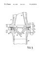
- FIG. 3 is a sectional view of the radar gauge shown mounted onto a nozzle of the tank shown in FIG. 1 and incorporating the window seal assembly of the present invention
- FIG. 4 is an enlarged fragmentary sectional view of one side of the installed window seal of the present invention shown installed between mounting flanges.
- a process tank or container 10 as shown has a process liquid 12 therein with a surface 14 , the height of which surface 10 is to be determined relative to the bottom of the tank.
- a radar gauge or transmitter 16 that transmits microwave energy through a horn antenna 18 , is positioned at the top of the tank 10 .
- the radar gauge or transmitter 16 is mounted on a cylindrical stand-off pipe or spool piece 20 that has a top flange 22 on which a flange 15 of the radar gauge or transmitter 16 is mounted.
- a spiral wound metal gasket 17 may be used between flanges 15 and 22 (FIG. 2 ).
- the stand off pipe 20 is cylindrical and surrounds the horn antenna 18 in the form shown.
- the stand off pipe 20 has a bottom flange 24 that is of standard size bolt pattern and shape (ANSI or DIN standard) to mate with a bounding support surface 25 of a standard size mounting flange 26 on the top of a nozzle or neck 28 on the tank 10 . All flanges have industry standard bolt circles.
- the nozzle or neck 28 is fixed to a top wall 29 of the tank and surrounds a port or opening 27 in the top wall. The port is bounded by the surface 25 of flange 26 .
- the tank 10 may be under high pressure, as well as relatively high temperature from time to time, and it is desirable to have a reliable isolation seal between the lower surface of the flange 24 of the stand off pipe 20 and the surface 25 of the mounting flange 26 . Since the radar gauge or transmitter 16 transmits and receives microwave energy for determining the level of the surface 14 , the isolation seal also has to be capable of transmitting microwave energy and thus it acts as a microwave radiation transmitting window. The process isolation window seal assembly also has to be pressure tight and fluid tight so that caustic materials, and sometimes even toxic materials that are contained within the tank 10 , are isolated from and not permitted to contact the antenna 18 or the more delicate radar gauge 16 .
- the thickness of the rim of the window seal between the surfaces of the flange 24 and the flange 26 is of concern because electromagnetic radiation or microwave energy can be scattered, or leak, through the material.
- the PTFE window seal has to be thick enough to withstand the pressures inside the tank.
- the tank or container 10 has the opening or port 27 on its upper side surrounded by the bounding surface 25 .
- the microwave gauge or transmitter 16 is provided above the opening 27 .
- An isolation microwave transmitting window seal assembly indicated generally at 30 comprises a window seal member 31 supported by an annular seal member mounting flange 32 on the bounding surface 25 .
- the seal member flange 32 has a periphery larger than the internal diameter of the opening 27 , the neck 28 and the stand-off pipe 20 .
- the flange 32 has a periphery 42 that is of size to fit within the bolts shown at 34 (FIG. 3) that are arranged in a standard bolt circle for standard flanges and which pass through aligning openings in the flange 24 and the flange 26 .
- the window seal member 31 including flange 32 thus is of size to overlie the port 27 on the container or tank and is supported on bounding surface 25 .
- the window seal member 31 is formed as an inverted cone indicated at 36 in its center section in the opening 27 .
- the cone 36 covers and seals the opening 27 formed by the neck 28 and extends down into the passageway formed by the neck 28 .
- the cone 36 provides a drip peak 38 at its lower end.
- the seal member flange supports the microwave transmitter or gauge 16 through the stand-off 20 above the opening 27 .
- the components of the isolation window seal assembly 30 are shown in FIG. 2 in exploded view and in FIGS. 3, and 4 in cross section.
- An electromagnetic interference shielding material ring 40 slips over the peripheral edge surface 42 of the seal member rim or flange 32 with a very close fit. The fit preferably is in the range of 0.015 inches, total clearance.
- the ring 40 has an outer peripheral wall 56 with an edge surface that has a groove 48 for holding a resilient O-ring 46 made of electromagnetic interference (EMI) shielding material to contain stray electromagnetic radiation.
- EMI electromagnetic interference
- the O-ring 46 seals on the bounding surface 25 .
- the EMI shielding O-ring 46 is made of a compressible material impregnated with metal flakes and is available from commercial sources such as Chomerics Division of Parker Hannifin PLC, Woburn, Mass., USA.
- the ring 40 is a containment ring and is used for controlling the maximum expansion of the periphery 42 of the seal member flange 32 radially outwardly from a center axis.
- the window seal member periphery 42 is retained within the confines of a peripheral wall 56 of the containment ring 40 to overcome tendencies of the rim or flange 32 to cold flow or to creep under clamping pressures or loading pressures.
- the containment ring 40 may be made of stainless steel or other suitable materials that provide electromagnetic interference shielding and the containment function.
- the isolation window seal rim or flange 32 has a shoulder groove 39 formed in its lower surface that is open to the periphery of the rim or flange 32 .
- a process environmental seal O-ring 41 made of suitable elastomeric material, that is chemically compatible with the tank contents so it will withstand the environment, is mounted in groove 39 .
- An elastomer sold under the trademark VITON has been found satisfactory for O-ring 41 .
- Parker Seal Group, O-Ring Division, of Lexington, Ky., USA makes suitable O-rings.
- the containment ring 40 includes an annular lip portion 54 overlying the seal member flange 32 adjacent the periphery of the seal member flange.
- Ring 40 is a continuous ring machined, as stated, to close diametral tolerances and also is of close tolerance in axial length (height) from the bottom surface of the annular lip 54 to the lower edge of the outer peripheral wall 56 .
- the annular lip 54 of containment ring 40 is integral with and at right angles to the outer peripheral wall 56 of the containment ring 40 .
- the lip 54 is also annular and surrounds a center opening that leaves the window seal member 31 unobstructed in regions above the opening 27 .
- the clamping from the flange bolts 34 will provide compression load through lip 54 on the isolation window seal flange 30 , and will load the environmental seal O-ring 41 when the ring 40 is clamped toward the bounding surface 25 .
- the O-ring groove 39 in the seal member opens to the periphery of the seal member flange 32 , and the peripheral wall 56 of the containment ring forms an annular outer side surface for the O-ring groove 39 .
- the cross section are of the lip 54 is smaller than the flanges 24 , and is selected to provide the appropriate loading on the flange 32 of the window seal.
- a conventional spiral wound metal gasket 50 is placed on top of the upper surface of the lip 54 , and is compressed against the lip 54 when the flange 24 is clamped toward flange 26 with bolts 34 .
- the spiral wound gasket 50 provides a compression seal between the upper surface of the lip 54 and the bottom surface of flange 24 of the spool piece or stand-off 20 .
- the spiral gasket is available from Lamons Gasket, Houston, Tex., USA.
- FIGS. 4 and 5 are enlarged views which show the groove 48 , and the EMI shielding O-ring 46 that seats down onto the bounding surface 25 of the flange 26 of the tank nozzle as the lip 54 of the containment ring 40 clamps onto flange 32 and the edge of the ring 40 moves toward the surface 25 .
- the EMI shielding O-ring 46 is carried by the containment ring 40 to seal on such bounding surface 25 as clamping forces are applied to the containment ring.
- the groove 39 in the seal member flange 32 is shown in FIG. 4 as well, and it can be seen that the process environmental seal O-ring 41 is contained by the inner surface of the annular band 56 of the containment ring 40 and the surface of shoulder groove 39 in the edge of seal member flange 32 .
- the seal member flange 32 is slightly thicker than the height 44 of the lip so as the bolts 34 are tightened there is a desired clamping force to compress the seal member flange 32 , the environmental O-ring 41 and EMI shielding O-ring 46 for sealing and for electromagnetic radiation shielding.
- Very high internal tank or container pressures can be withstood without failure. Also, pressure leakage over time is very low because of the containment ring and the seals.
- Another aspect of the invention comprises a method of sealing the opening 27 bounded by surface 25 using window seal member 31 to overlie the opening 27 .
- the seal member 31 has a periphery 42 defining a seal member flange portion 32 overlying the bounding surface 25 .
- the method comprises the step of encircling the periphery of the window seal member 31 with a containment ring 40 made of electromagnetic interference (EMI) shielding material and placing a compressible EMI shielding material between the edge of the ring 40 and the bounding surfaces.
- EMI electromagnetic interference
- the method includes one aspect forming the ring 40 of size to control the maximum peripheral size of the seal member 31 under clamping forces adjacent the periphery of the seal member from bolts 34 and under pressures acting on the seal member 31 through further forming a pressure seal between the bounding surface 25 and the seal member 31 with an environmental O-ring 41 , which is held in a groove 39 with the containment ring 40 is part of the method.
- the containment ring 40 functions well with other configurations of isolation window seal members as well, because the containment ring will prevent the expansion of the peripheral dimensions of the periphery 42 of the isolation window seal member if the isolation window seal member creeps or cold flows.
- lenticular seals, planar or plate seals, and other geometric configurations will benefit from the containment ring shown.
- the window seal arrangement permits removal of the radar gauge or transmitter and horn antenna without disturbing the isolation window seal, so the tank contents will not be exposed to atmosphere. This permits maintenance or replacement of the radar gauge without breaking the tank seal.
Abstract
A process seal made of a material such as polytetrafluoroethylene is used as a microwave window in a radar tank level gauge. The periphery of the process seal is surrounded by a metal containment ring that is fitted to the periphery to limit the amount of expansion outwardly of the process seal material as well as provide for localized loading at the periphery for clamping pressures on the seal. Electromagnetic radiation shielding is provided not only by the containment ring, but also by an EMI shielding O-ring mounted in a groove on a sealing end of the containment ring. A process environmental O-ring is carried by the process seal in an outer shoulder groove that is enclosed by the containment ring.
Description
This application claims the priority of earlier filed co-pending Provisional patent application No. 60/108,050 filed Nov. 12, 1998 and entitled PTFE WINDOW SEAL WITH EMI SHIELDING.
The present invention relates to a process window seal that will transmit microwave energy and includes a surrounding ring with seals to reduce or prevent microwave energy leakage. The ring contains the window seal to avoid creep or cold flow across a wide range of temperatures to avoid failures under operating pressures.
In the past, there have been considerable developments in the use of microwave (radar) gauges for determining tank levels. These gauges depend upon transmitting microwave energy toward a surface of material inside a tank or container, and then receiving an echo or return signal to determine the level of the material sending the echo. The correct type of device depends in part on the overall distance that needs to be measured, that is the height of the material in the tank between its lowest level and its highest level. Also, the surface conditions of the materials are of importance in measuring tank level, as are the dielectric constant or conductivity of the material to be measured.
In using a radar gauge, the process tank or container that is to be monitored can sometimes be at a very high temperature, as well as at a high pressure. In such instances, it is necessary to have a pressure containing window seal between the radar instrument and the interior of the tank, to protect the instrument from harsh, corrosive process materials. The window seal has to be able to transmit microwave energy for operation of the radar gauge.
Various manufacturers have advanced radar gauges, including the MICROPILOT radar gauge made and sold by Endress+Hauser. These devices are used for determining levels of various materials.
Window seals made of polytetrafluoroethylene (PTFE) are commonly used, but under high temperatures and high pressures they will tend to flow, so that the pressure carrying capability is reduced at such high temperatures. Usually the need for high pressure performance is when the temperature is high as well. Thus, being able to control the flowing of the PTFE at process temperatures is desirable for maximum utilization of the window materials.
The present invention relates to a process isolator seal and microwave energy transmitting assembly for determining the level of material in a container. The container has a top opening surrounded by a bounding surface. A microwave energy gauge or transmitter is mounted above the opening on a microwave transmissive window seal member which is of size to close the opening, and which has a flange supported on the bounding surface. An electromagnetic shielding material containment ring surrounds the microwave window seal member and encloses the edge surface of the microwave window seal member. The edge of the containment ring carries a resilient electromagnetic shielding O-ring that also seals on the bounding surface. The containment ring preferably controls the peripheral size of the microwave window seal member under clamping forces adjacent the periphery of the seal.
The container as shown is a process fluid tank on which a microwave radar level gauge or transmitter is mounted. As shown, a support flange of the window seal is clamped between the bounding surface on the tank flange on the customer's tank, and a stand off pipe that surrounds a horn antenna on the microwave level gauge or transmitter. The clamping of the microwave window seal member between flanges will retain it securely, and create a seal, but under high tank pressures, and high temperature and humidity, and with highly corrosive materials, the preferred PTFE material for the window seal member will tend to cold flow or to creep. Creep can occur even under lower temperatures when the pressures are high. The containment ring surrounding the window seal member controls the amount of creep or cold flow radially outwardly, thereby reducing the shear stress in the PTFE and increasing the pressure rating for a given temperature in a comparable size seal.
The containment ring helps to maintain the shape of the PTFE window seal member over time. The containment ring preferably has an inwardly extending lip that overlies a portion of the seal flange. Clamping forces are applied to the containment ring, and the lip provides a cross sectional area engaging the seal flange on which the applied clamping loads act that is less than the stand off pipe flange. Also, the load from pressure in the process fluid tank is applied over this smaller cross sectional area defined by the lip of the containment ring. Shear stress is reduced and the pressure rating is increased.
The containment ring is made of a material such as stainless steel, which provides the electromagnetic interference (EMI) shielding. Other gaps where microwave radiation can escape are closed by an O-ring that contains materials which will provide EMI shielding between the edge of the containment ring and the bounding surface. The O-ring also forms a pressure seal between the edge of the containment ring and the bounding surface of the tank flange.
The reduction in stray electromagnetic radiation emissions from the radar gauge or transmitter permits installation without obtaining a separate license from agencies such as the Federal Communications Commission.
A metal, spiral gasket is used above the lip of the containment ring and is clamped in place with the stand off ring to further increase the integrity of the seal.
A process fluid environmental seal O-ring also can be provided on the PTFE window seal. As shown the O-ring is mounted in a shouldered groove open at the periphery of the PTFE window seal flange. The containment ring closes the shouldered groove so the environmental seal O-ring is trapped in place.
FIG. 1 is a schematic representation of a typical process material tank that has a radar level gauge or transmitter mounted thereon, utilizing a window seal assembly of the present invention;
FIG. 2 is an exploded view of the window seal assembly of the present invention;
FIG. 3 is a sectional view of the radar gauge shown mounted onto a nozzle of the tank shown in FIG. 1 and incorporating the window seal assembly of the present invention;
FIG. 4 is an enlarged fragmentary sectional view of one side of the installed window seal of the present invention shown installed between mounting flanges.
A process tank or container 10 as shown has a process liquid 12 therein with a surface 14, the height of which surface 10 is to be determined relative to the bottom of the tank. A radar gauge or transmitter 16 that transmits microwave energy through a horn antenna 18, is positioned at the top of the tank 10. The radar gauge or transmitter 16 is mounted on a cylindrical stand-off pipe or spool piece 20 that has a top flange 22 on which a flange 15 of the radar gauge or transmitter 16 is mounted. A spiral wound metal gasket 17 may be used between flanges 15 and 22 (FIG. 2). The stand off pipe 20 is cylindrical and surrounds the horn antenna 18 in the form shown.
The stand off pipe 20 has a bottom flange 24 that is of standard size bolt pattern and shape (ANSI or DIN standard) to mate with a bounding support surface 25 of a standard size mounting flange 26 on the top of a nozzle or neck 28 on the tank 10. All flanges have industry standard bolt circles. The nozzle or neck 28 is fixed to a top wall 29 of the tank and surrounds a port or opening 27 in the top wall. The port is bounded by the surface 25 of flange 26.
The tank 10 may be under high pressure, as well as relatively high temperature from time to time, and it is desirable to have a reliable isolation seal between the lower surface of the flange 24 of the stand off pipe 20 and the surface 25 of the mounting flange 26. Since the radar gauge or transmitter 16 transmits and receives microwave energy for determining the level of the surface 14, the isolation seal also has to be capable of transmitting microwave energy and thus it acts as a microwave radiation transmitting window. The process isolation window seal assembly also has to be pressure tight and fluid tight so that caustic materials, and sometimes even toxic materials that are contained within the tank 10, are isolated from and not permitted to contact the antenna 18 or the more delicate radar gauge 16.
The thickness of the rim of the window seal between the surfaces of the flange 24 and the flange 26 is of concern because electromagnetic radiation or microwave energy can be scattered, or leak, through the material. The PTFE window seal has to be thick enough to withstand the pressures inside the tank.
The tank or container 10 has the opening or port 27 on its upper side surrounded by the bounding surface 25. The microwave gauge or transmitter 16 is provided above the opening 27. An isolation microwave transmitting window seal assembly indicated generally at 30 comprises a window seal member 31 supported by an annular seal member mounting flange 32 on the bounding surface 25. The seal member flange 32 has a periphery larger than the internal diameter of the opening 27, the neck 28 and the stand-off pipe 20. The flange 32 has a periphery 42 that is of size to fit within the bolts shown at 34 (FIG. 3) that are arranged in a standard bolt circle for standard flanges and which pass through aligning openings in the flange 24 and the flange 26. The window seal member 31 including flange 32 thus is of size to overlie the port 27 on the container or tank and is supported on bounding surface 25.
In this form of the invention, the window seal member 31 is formed as an inverted cone indicated at 36 in its center section in the opening 27. The cone 36 covers and seals the opening 27 formed by the neck 28 and extends down into the passageway formed by the neck 28. The cone 36 provides a drip peak 38 at its lower end.
The seal member flange supports the microwave transmitter or gauge 16 through the stand-off 20 above the opening 27.
The components of the isolation window seal assembly 30 are shown in FIG. 2 in exploded view and in FIGS. 3, and 4 in cross section. An electromagnetic interference shielding material ring 40, slips over the peripheral edge surface 42 of the seal member rim or flange 32 with a very close fit. The fit preferably is in the range of 0.015 inches, total clearance. The ring 40 has an outer peripheral wall 56 with an edge surface that has a groove 48 for holding a resilient O-ring 46 made of electromagnetic interference (EMI) shielding material to contain stray electromagnetic radiation. The O-ring 46 seals on the bounding surface 25. The EMI shielding O-ring 46 is made of a compressible material impregnated with metal flakes and is available from commercial sources such as Chomerics Division of Parker Hannifin PLC, Woburn, Mass., USA.
The ring 40 is a containment ring and is used for controlling the maximum expansion of the periphery 42 of the seal member flange 32 radially outwardly from a center axis. The window seal member periphery 42 is retained within the confines of a peripheral wall 56 of the containment ring 40 to overcome tendencies of the rim or flange 32 to cold flow or to creep under clamping pressures or loading pressures. The containment ring 40 may be made of stainless steel or other suitable materials that provide electromagnetic interference shielding and the containment function.
The isolation window seal rim or flange 32 has a shoulder groove 39 formed in its lower surface that is open to the periphery of the rim or flange 32. A process environmental seal O-ring 41, made of suitable elastomeric material, that is chemically compatible with the tank contents so it will withstand the environment, is mounted in groove 39. An elastomer sold under the trademark VITON has been found satisfactory for O-ring 41. Parker Seal Group, O-Ring Division, of Lexington, Ky., USA makes suitable O-rings.
The containment ring 40 includes an annular lip portion 54 overlying the seal member flange 32 adjacent the periphery of the seal member flange. Ring 40 is a continuous ring machined, as stated, to close diametral tolerances and also is of close tolerance in axial length (height) from the bottom surface of the annular lip 54 to the lower edge of the outer peripheral wall 56.
The annular lip 54 of containment ring 40 is integral with and at right angles to the outer peripheral wall 56 of the containment ring 40. The lip 54 is also annular and surrounds a center opening that leaves the window seal member 31 unobstructed in regions above the opening 27.
The clamping from the flange bolts 34 will provide compression load through lip 54 on the isolation window seal flange 30, and will load the environmental seal O-ring 41 when the ring 40 is clamped toward the bounding surface 25. The O-ring groove 39 in the seal member opens to the periphery of the seal member flange 32, and the peripheral wall 56 of the containment ring forms an annular outer side surface for the O-ring groove 39. The cross section are of the lip 54 is smaller than the flanges 24, and is selected to provide the appropriate loading on the flange 32 of the window seal.
A conventional spiral wound metal gasket 50 is placed on top of the upper surface of the lip 54, and is compressed against the lip 54 when the flange 24 is clamped toward flange 26 with bolts 34. The spiral wound gasket 50 provides a compression seal between the upper surface of the lip 54 and the bottom surface of flange 24 of the spool piece or stand-off 20. The spiral gasket is available from Lamons Gasket, Houston, Tex., USA.
It should be understood that with different antennas, the stand-off pipe 20 can be varied in configuration, and if no antenna is necessary or if there is a need for having an antenna protruding partially into the customer's tank nozzle, the PTFE isolation window seal 30 can be formed to surround the antenna, and the flange of the level gauge or transmitter housing can be clamped against the lip 54.
As shown perhaps best in FIGS. 3 and 4, the seal member rim or flange 32 is resting on bounding surface 25 of flange 26 of the neck 28, and the window seal member 31 extends across the port or opening 27 formed by the neck and leading to the container or tank 10. FIGS. 4 and 5 are enlarged views which show the groove 48, and the EMI shielding O-ring 46 that seats down onto the bounding surface 25 of the flange 26 of the tank nozzle as the lip 54 of the containment ring 40 clamps onto flange 32 and the edge of the ring 40 moves toward the surface 25. The EMI shielding O-ring 46 is carried by the containment ring 40 to seal on such bounding surface 25 as clamping forces are applied to the containment ring.
The groove 39 in the seal member flange 32 is shown in FIG. 4 as well, and it can be seen that the process environmental seal O-ring 41 is contained by the inner surface of the annular band 56 of the containment ring 40 and the surface of shoulder groove 39 in the edge of seal member flange 32.
The bolts 34 that are used for clamping the flanges 24 and 26 together are tightened to the desired torque, and the annular lip 54 of the containment ring 40 will provide load against the outer portions of the seal member flange 32 of window seal member 31. This insures adequate seal pressure on the seal member flange 32 across a wide range of internal tank pressures and temperatures, and also causes compression of O-ring 41
The seal member flange 32 is slightly thicker than the height 44 of the lip so as the bolts 34 are tightened there is a desired clamping force to compress the seal member flange 32, the environmental O-ring 41 and EMI shielding O-ring 46 for sealing and for electromagnetic radiation shielding. Very high internal tank or container pressures can be withstood without failure. Also, pressure leakage over time is very low because of the containment ring and the seals.
Another aspect of the invention comprises a method of sealing the opening 27 bounded by surface 25 using window seal member 31 to overlie the opening 27. The seal member 31 has a periphery 42 defining a seal member flange portion 32 overlying the bounding surface 25. The method comprises the step of encircling the periphery of the window seal member 31 with a containment ring 40 made of electromagnetic interference (EMI) shielding material and placing a compressible EMI shielding material between the edge of the ring 40 and the bounding surfaces. The method includes one aspect forming the ring 40 of size to control the maximum peripheral size of the seal member 31 under clamping forces adjacent the periphery of the seal member from bolts 34 and under pressures acting on the seal member 31 through further forming a pressure seal between the bounding surface 25 and the seal member 31 with an environmental O-ring 41, which is held in a groove 39 with the containment ring 40 is part of the method.
While a conical shape isolation window seal member has been shown, the containment ring 40 functions well with other configurations of isolation window seal members as well, because the containment ring will prevent the expansion of the peripheral dimensions of the periphery 42 of the isolation window seal member if the isolation window seal member creeps or cold flows. Thus, lenticular seals, planar or plate seals, and other geometric configurations will benefit from the containment ring shown.
The window seal arrangement permits removal of the radar gauge or transmitter and horn antenna without disturbing the isolation window seal, so the tank contents will not be exposed to atmosphere. This permits maintenance or replacement of the radar gauge without breaking the tank seal.
Although the present invention has been described with reference to preferred embodiments, workers skilled in the art will recognize that changes may be made in form and detail without departing from the spirit and scope of the invention.
Claims (25)
1. A process isolation window seal and microwave energy transmitting assembly used for determining the level of a material in a container having an opening in an upper side, the opening being surrounded by a bounding surface, the seal and assembly comprising:
a microwave transmissive seal member of size to close the opening of the container and having a seal member flange of size to be supported on the bounding surface of the container, microwave energy being transmitted through the seal member;
an electromagnetic interference (EMI) shielding material first ring surrounding a periphery of the seal member flange and having a height substantially to enclose an edge surface of the seal member flange, an edge surface of said first ring positioned to face the bounding surface of the opening of the container and having a groove formed therein surrounding the seal member flange; and
a resilient second ring of material that provides electromagnetic interference shielding mounted in said groove for sealing on the bounding surface.
2. The assembly of claim 1, wherein said first ring comprises a containment ring and is sized to surround the seal member flange with a clearance to control the expansion of the seal member flange radially outward from a center axis.
3. The assembly of claim 2, wherein said containment ring includes a lip portion overlying the seal member flange adjacent peripheral edges of the seal member flange, said lip portion being compressed against said seal member flange when the seal member flange and containment ring are clamped toward the bounding surface.
4. The assembly of claim 1, wherein the periphery of said seal member flange is substantially circular, and said first ring has a mating interior surface.
5. The assembly of claim 1, wherein the height of said first ring from the first ring edge surface engaging the seal member flange is less than the height of the seal member flange.
6. The assembly of claim 5, wherein said first ring is made of a stainless steel.
7. The assembly of claim 6, wherein said seal member is made of polytetrafluoroethylene.
8. The assembly of claim 1 wherein an O-ring groove is formed at an outer edge of the seal member flange and is enclosed on one side by an interior surface of the first ring.
9. A process isolation window seal assembly for transmitting energy therethrough in association with a material in a container, wherein there is an opening to the container, and the opening is bounded by a bounding surface, the assembly comprising:
a seal member of size to overlie the opening on the container and to be supported on the bounding surface, the seal member having a periphery;
a containment ring surrounding the seal member to control the peripheral size of the seal member under clamping forces adjacent the periphery of the seal member; and
wherein said containment ring has a surface to overlie on the bounding surface of the container opening, and an EMI shielding O-ring seal is carried by the containment ring to seal the bounding surface as clamping forces are applied to the containment ring.
10. The process window seal of claim 9, wherein the containment ring comprises an electromagnetic interference shielding material.
11. The process window seal of claim 9 and an O-ring groove formed in the seal member adjacent a periphery of the seal member and being open in an outwardly facing direction, said containment ring forming an annular outer side surface of the O-ring groove.
12. The process window seal of claim 11 and a separate O-ring mounted in the containment ring to engage the bounding surface, the separate O-ring comprising a material providing electromagnetic interference shielding.
13. The process window seal of claim 9 and a stand-off pipe comprising a tubular member having a first flange clampable with respect to a container for applying the clamping forces to the containment ring and seal member, a microwave transmitter level gauge mountable on the stand-off pipe at an opposite end from the first flange, and a microwave antenna extendable into and surrounded by the stand-off pipe, the seal member comprising a microwave transmitting material.
14. The process window seal of claim 9, wherein said containment ring includes a peripheral wall portion surrounding the seal member, and a clamping lip portion overlying a portion of the seal member that is to be supported on the bounding surface, the lip portion carrying clamping force to the seal member when the seal member is supported on the bounding surface.
15. The process window seal of claim 14, wherein the peripheral wall portion of said containment ring has a lower edge, an O-ring groove formed in the lower edge, and a compressible ring mounted in said O-ring groove, said compressible ring comprising a material providing electromagnetic interference shielding.
16. The process window seal of claim 15, wherein said seal member has a conical exterior surface.
17. A method of sealing an opening bounded by a surface using a seal member overlying the opening, the seal member having a periphery defining a portion overlying the bounding surface, comprising the steps of encircling the periphery of the seal member with a containment ring made of electromagnetic interference shielding material, the ring having an edge surface facing the bounding surface, and providing compressible resilient material that provides electromagnetic shielding between the edge surface and the bounding surface to control a maximum peripheral size of the seal member under clamping forces adjacent the periphery of the seal member and under pressures acting on the seal through the opening.
18. The method of claim 17, including the step of forming the containment ring to surround the seal member with clearance.
19. The method of claim 17, including the step of forming the seal member of polytetrafluoroethylene and forming central portions of the seal member into a conical shape.
20. The method of claim 18 including the step of providing a pressure seal between the bounding surface and the seal member, and containing the pressure seal with the containment ring.
21. The method of claim 19 including the step of clamping the portions of the seal member overlying the bounding surface of the opening with a lip on the containment ring.
22. A process seal adapted for transmitting energy therethrough in association with material in a container, a port open to the container, the opening being bounded by a sealing surface, the seal comprising:
seal means for sealing the opening and having a peripheral flange means for being supported and sealing on the sealing surface, the seal means having a periphery;
containment ring means for controlling the peripheral size of the seal means under tendencies of the seal means to change maximum peripheral dimension; and
a resilient ring means for shielding electromagnetic interference and sealing between the containment ring means and the sealing surface.
23. The process seal of claim 22 and further comprising groove means for opening outwardly in a radial direction and being bounded by the containment ring means, and O-ring means for providing a seal on the sealing surface.
24. The process seal of claim 22, wherein said containment ring means has ring lip means for extending inwardly to overlie a portion of the peripheral flange means and for providing clamping forces at a defined region of the peripheral flange means when the containment ring means is clamped toward the sealing surface.
25. The process seal of claim 24, wherein the seal is sized for use with a standard process pipe flange having a standard bolt circle.
Priority Applications (5)
| Application Number | Priority Date | Filing Date | Title |
|---|---|---|---|
| US09/301,419 US6325391B1 (en) | 1998-11-12 | 1999-04-28 | PTFE window seal with EMI shielding |
| AU16138/00A AU1613800A (en) | 1998-11-12 | 1999-11-10 | Ptfe window seal with emi shielding |
| PCT/US1999/026468 WO2000029819A1 (en) | 1998-11-12 | 1999-11-10 | Ptfe window seal with emi shielding |
| DE19982569T DE19982569B3 (en) | 1998-11-12 | 1999-11-10 | PTFE window seal with EMB shielding |
| CA002317427A CA2317427A1 (en) | 1998-11-12 | 1999-11-10 | Ptfe window seal with emi shielding |
Applications Claiming Priority (2)
| Application Number | Priority Date | Filing Date | Title |
|---|---|---|---|
| US10805098P | 1998-11-12 | 1998-11-12 | |
| US09/301,419 US6325391B1 (en) | 1998-11-12 | 1999-04-28 | PTFE window seal with EMI shielding |
Publications (1)
| Publication Number | Publication Date |
|---|---|
| US6325391B1 true US6325391B1 (en) | 2001-12-04 |
Family
ID=26805473
Family Applications (1)
| Application Number | Title | Priority Date | Filing Date |
|---|---|---|---|
| US09/301,419 Expired - Lifetime US6325391B1 (en) | 1998-11-12 | 1999-04-28 | PTFE window seal with EMI shielding |
Country Status (5)
| Country | Link |
|---|---|
| US (1) | US6325391B1 (en) |
| AU (1) | AU1613800A (en) |
| CA (1) | CA2317427A1 (en) |
| DE (1) | DE19982569B3 (en) |
| WO (1) | WO2000029819A1 (en) |
Cited By (20)
| Publication number | Priority date | Publication date | Assignee | Title |
|---|---|---|---|---|
| WO2003048697A1 (en) * | 2001-12-05 | 2003-06-12 | Saab Marine Electronics Ab | Radar antenna |
| US20050099349A1 (en) * | 2001-11-16 | 2005-05-12 | Torbjorn Krig | Slot antenna |
| US20050127924A1 (en) * | 2003-12-11 | 2005-06-16 | Ohmart/Vega Corporation | Apparatus for use in measuring fluid levels |
| DE102004022516A1 (en) * | 2004-05-05 | 2005-12-01 | Endress + Hauser Gmbh + Co. Kg | horn antenna |
| US20060055591A1 (en) * | 2004-09-10 | 2006-03-16 | Saab Rosemount Rank Radar Ab | Radar level gauge with switch for selecting transmitter or receiver mode |
| US20060071848A1 (en) * | 2004-10-01 | 2006-04-06 | Saab Rosemount Tank Radar Ab | Microwave sealing for radar level gauges |
| US20060109010A1 (en) * | 2004-11-24 | 2006-05-25 | Saab Rosemount Tank Radar Ab | Antenna device for level gauging |
| US20070008212A1 (en) * | 2005-06-13 | 2007-01-11 | Gabriel Serban | Horn antenna with a composite emitter for a radar-based level measurement system |
| US20110221629A1 (en) * | 2010-03-10 | 2011-09-15 | Olov Edvardsson | Radar level gauge with improved radar window |
| US20140266864A1 (en) * | 2013-03-12 | 2014-09-18 | Rosemount Tank Radar Ab | Tank feed through structure for a radar level gauge |
| WO2015000656A1 (en) * | 2013-07-03 | 2015-01-08 | Endress+Hauser Gmbh+Co. Kg | Antenna assembly for a fill-level measuring device |
| US20160153820A1 (en) * | 2014-10-13 | 2016-06-02 | Honeywell International Inc. | Use of resilient seals for high temperature and/or high pressure sealing in a guided wave radar level measurement device |
| US20160209261A1 (en) * | 2015-01-16 | 2016-07-21 | Savage Services Corporation | Vessel fluid measurement assemblies and related systems and methods |
| US20160273954A1 (en) * | 2013-12-06 | 2016-09-22 | Endress+Hauser Gmbh+Co. Kg | Apparatus for determining fill level of a fill substance in a container |
| CN106415216A (en) * | 2014-03-28 | 2017-02-15 | 霍尼韦尔国际公司 | Threaded coupling device with nozzle for GWR measurements in non-metallic tanks |
| EP3165883A1 (en) * | 2015-11-05 | 2017-05-10 | VEGA Grieshaber KG | Fill level radar sensor with shielding |
| JP6195966B1 (en) * | 2016-10-26 | 2017-09-13 | メイク株式会社 | Radio wave level meter and mounting method of radio wave level meter |
| RU2656027C2 (en) * | 2013-03-12 | 2018-05-30 | Роузмаунт Танк Радар Аб | Radar level gauge |
| EP3736544A1 (en) * | 2019-05-06 | 2020-11-11 | Rosemount Tank Radar AB | Radar level gauge with sealing dielectric filling member and structurally reinforced element |
| WO2022115933A1 (en) * | 2020-12-01 | 2022-06-09 | Pathronix Corp. | Variable power cold microwave tissue processor |
Families Citing this family (7)
| Publication number | Priority date | Publication date | Assignee | Title |
|---|---|---|---|---|
| DE102010031276A1 (en) | 2010-07-13 | 2012-01-19 | Endress + Hauser Gmbh + Co. Kg | Level gauge for determining and monitoring a level of a medium in the process chamber of a container by means of a microwave transit time measurement method |
| DE102014103378A1 (en) * | 2014-03-13 | 2015-09-17 | Krohne Messtechnik Gmbh | Measuring arrangement for determining and / or monitoring at least one measured variable of a medium |
| HUE039704T2 (en) | 2014-04-08 | 2019-01-28 | Grieshaber Vega Kg | Protection device for a wave guide |
| ES2787043T3 (en) * | 2016-02-09 | 2020-10-14 | Vega Americas Inc | Apparatus and method for liquid level measurement and content purity measurement in a sounding tube |
| EP3569990B1 (en) * | 2018-05-17 | 2021-02-17 | VEGA Grieshaber KG | Attachment assembly for a radar fill level measuring device |
| DE102020201954B4 (en) * | 2020-02-17 | 2023-08-10 | Vega Grieshaber Kg | Protective device for sealing a sensor device |
| DE102021123532A1 (en) | 2021-09-10 | 2023-03-16 | Krohne Messtechnik Gmbh | System consisting of a level gauge for measuring the level of a medium in a container and an attachment and attachment |
Citations (17)
| Publication number | Priority date | Publication date | Assignee | Title |
|---|---|---|---|---|
| US3019281A (en) * | 1960-03-04 | 1962-01-30 | Tech Wire Prod Inc | Electrical shielding and sealing gasket |
| US4566321A (en) | 1985-01-18 | 1986-01-28 | Transamerica Delaval Inc. | Microwave tank-contents level measuring assembly with lens-obturated wall-opening |
| US4932673A (en) * | 1988-02-01 | 1990-06-12 | Hughes Aircraft Company | Emi suppression gasket for millimeter waveguides |
| US5061467A (en) | 1988-03-08 | 1991-10-29 | Rom Industries Corporation | Economic recovery and utilization of boiler flue gas pollutants |
| US5115218A (en) | 1991-03-11 | 1992-05-19 | Baker Hughes Inc. | Microwave process seal and method |
| US5115104A (en) * | 1991-03-29 | 1992-05-19 | Chomerics, Inc. | EMI/RFI shielding gasket |
| US5117066A (en) * | 1988-04-25 | 1992-05-26 | Peter J. Balsells | Retaining and locking electromagnetic gasket |
| US5200722A (en) | 1991-11-27 | 1993-04-06 | United Solar Systems Corporation | Microwave window assembly |
| US5305237A (en) | 1991-07-12 | 1994-04-19 | Union Tank Car Company | Method and apparatus for monitoring a flowable material in a transportable vessel |
| US5495218A (en) | 1994-04-20 | 1996-02-27 | Thermo Instrument Controls Inc. | Microwave waveguide seal assembly |
| US5507181A (en) * | 1993-12-27 | 1996-04-16 | Motorola, Inc. | Non-intrusive mounting system and method for microwave instruments |
| US5508712A (en) | 1994-03-28 | 1996-04-16 | P-Com, Inc. | Self-aligning wave guide interface |
| US5594449A (en) | 1993-10-26 | 1997-01-14 | Endress + Hauser Gmbh + Co. | Tank-contents level measuring assembly |
| US5703289A (en) | 1995-02-01 | 1997-12-30 | Magnetrol International, Inc. | Microwave transmitter housing |
| US5770990A (en) | 1995-11-15 | 1998-06-23 | Krohne Messtechnik Gmbh & Co. Kg | Microwave window |
| EP0992942A1 (en) | 1998-10-05 | 2000-04-12 | Agfa-Gevaert N.V. | Method for smoothing staircase effect in enlarged low resolution images |
| US6155112A (en) | 1996-10-04 | 2000-12-05 | Endress + Hauser Gmbh + Co. | Filling level measuring device operating with microwaves |
Family Cites Families (2)
| Publication number | Priority date | Publication date | Assignee | Title |
|---|---|---|---|---|
| GB1600710A (en) * | 1977-06-30 | 1981-10-21 | Chomerics Inc | Corrosion resistant electromagnetic energy shielding gasket |
| DE4407823C2 (en) * | 1994-03-09 | 1997-12-11 | Grieshaber Vega Kg | Level measuring device |
-
1999
- 1999-04-28 US US09/301,419 patent/US6325391B1/en not_active Expired - Lifetime
- 1999-11-10 WO PCT/US1999/026468 patent/WO2000029819A1/en active Application Filing
- 1999-11-10 CA CA002317427A patent/CA2317427A1/en not_active Abandoned
- 1999-11-10 DE DE19982569T patent/DE19982569B3/en not_active Expired - Fee Related
- 1999-11-10 AU AU16138/00A patent/AU1613800A/en not_active Abandoned
Patent Citations (17)
| Publication number | Priority date | Publication date | Assignee | Title |
|---|---|---|---|---|
| US3019281A (en) * | 1960-03-04 | 1962-01-30 | Tech Wire Prod Inc | Electrical shielding and sealing gasket |
| US4566321A (en) | 1985-01-18 | 1986-01-28 | Transamerica Delaval Inc. | Microwave tank-contents level measuring assembly with lens-obturated wall-opening |
| US4932673A (en) * | 1988-02-01 | 1990-06-12 | Hughes Aircraft Company | Emi suppression gasket for millimeter waveguides |
| US5061467A (en) | 1988-03-08 | 1991-10-29 | Rom Industries Corporation | Economic recovery and utilization of boiler flue gas pollutants |
| US5117066A (en) * | 1988-04-25 | 1992-05-26 | Peter J. Balsells | Retaining and locking electromagnetic gasket |
| US5115218A (en) | 1991-03-11 | 1992-05-19 | Baker Hughes Inc. | Microwave process seal and method |
| US5115104A (en) * | 1991-03-29 | 1992-05-19 | Chomerics, Inc. | EMI/RFI shielding gasket |
| US5305237A (en) | 1991-07-12 | 1994-04-19 | Union Tank Car Company | Method and apparatus for monitoring a flowable material in a transportable vessel |
| US5200722A (en) | 1991-11-27 | 1993-04-06 | United Solar Systems Corporation | Microwave window assembly |
| US5594449A (en) | 1993-10-26 | 1997-01-14 | Endress + Hauser Gmbh + Co. | Tank-contents level measuring assembly |
| US5507181A (en) * | 1993-12-27 | 1996-04-16 | Motorola, Inc. | Non-intrusive mounting system and method for microwave instruments |
| US5508712A (en) | 1994-03-28 | 1996-04-16 | P-Com, Inc. | Self-aligning wave guide interface |
| US5495218A (en) | 1994-04-20 | 1996-02-27 | Thermo Instrument Controls Inc. | Microwave waveguide seal assembly |
| US5703289A (en) | 1995-02-01 | 1997-12-30 | Magnetrol International, Inc. | Microwave transmitter housing |
| US5770990A (en) | 1995-11-15 | 1998-06-23 | Krohne Messtechnik Gmbh & Co. Kg | Microwave window |
| US6155112A (en) | 1996-10-04 | 2000-12-05 | Endress + Hauser Gmbh + Co. | Filling level measuring device operating with microwaves |
| EP0992942A1 (en) | 1998-10-05 | 2000-04-12 | Agfa-Gevaert N.V. | Method for smoothing staircase effect in enlarged low resolution images |
Non-Patent Citations (2)
| Title |
|---|
| Published Advertisement MeasureTech(TM)RCM Features and Benefits, date not available (undated). |
| Published Advertisement MeasureTech™RCM Features and Benefits, date not available (undated). |
Cited By (45)
| Publication number | Priority date | Publication date | Assignee | Title |
|---|---|---|---|---|
| US7165449B2 (en) * | 2001-11-16 | 2007-01-23 | Saab Rosemount Tank Radar Ab | Slot antenna |
| US20050099349A1 (en) * | 2001-11-16 | 2005-05-12 | Torbjorn Krig | Slot antenna |
| US6684697B1 (en) | 2001-12-05 | 2004-02-03 | Saab Marine Electronics Ab | Radar antenna |
| WO2003048697A1 (en) * | 2001-12-05 | 2003-06-12 | Saab Marine Electronics Ab | Radar antenna |
| US20070137021A1 (en) * | 2003-12-11 | 2007-06-21 | Ohmart/Vega Corporation | Apparatus for use in measuring fluid levels |
| US7237435B2 (en) | 2003-12-11 | 2007-07-03 | Ohmart/Vega Corporation | Apparatus for use in measuring fluid levels |
| US20050127924A1 (en) * | 2003-12-11 | 2005-06-16 | Ohmart/Vega Corporation | Apparatus for use in measuring fluid levels |
| US7392699B2 (en) * | 2003-12-11 | 2008-07-01 | Ohmart/Vega Corporation | Apparatus for use in measuring fluid levels |
| US6988404B2 (en) * | 2003-12-11 | 2006-01-24 | Ohmart/Vega Corporation | Apparatus for use in measuring fluid levels |
| US20060090562A1 (en) * | 2003-12-11 | 2006-05-04 | Ohmart/Vega Corporation | Apparatus for use in measuring fluid levels |
| DE102004022516B4 (en) * | 2004-05-05 | 2017-01-19 | Endress + Hauser Gmbh + Co. Kg | horn antenna |
| DE102004022516A1 (en) * | 2004-05-05 | 2005-12-01 | Endress + Hauser Gmbh + Co. Kg | horn antenna |
| US20060055591A1 (en) * | 2004-09-10 | 2006-03-16 | Saab Rosemount Rank Radar Ab | Radar level gauge with switch for selecting transmitter or receiver mode |
| CN101014875B (en) * | 2004-09-10 | 2011-01-19 | 罗斯蒙特雷达液位股份公司 | Radar level gauge with switch for selecting transmitter or receiver mode |
| US7233278B2 (en) * | 2004-09-10 | 2007-06-19 | Rosemount Tank Radar Ab | Radar level gauge with switch for selecting transmitter or receiver mode |
| US20060071848A1 (en) * | 2004-10-01 | 2006-04-06 | Saab Rosemount Tank Radar Ab | Microwave sealing for radar level gauges |
| US7239267B2 (en) | 2004-10-01 | 2007-07-03 | Rosemount Tank Radar Ab | Microwave sealing for radar level gauges |
| WO2006038861A1 (en) | 2004-10-01 | 2006-04-13 | Rosemount Tank Radar Ab | Microwave sealing for radar level gauges |
| US20070252752A1 (en) * | 2004-10-01 | 2007-11-01 | Olov Edvardsson | Microwave sealing for radar level gauging |
| US20060109010A1 (en) * | 2004-11-24 | 2006-05-25 | Saab Rosemount Tank Radar Ab | Antenna device for level gauging |
| US7173436B2 (en) | 2004-11-24 | 2007-02-06 | Saab Rosemount Tank Radar Ag | Antenna device for level gauging |
| US7602330B2 (en) * | 2005-06-13 | 2009-10-13 | Siemens Milltronics Process Instruments, Inc. | Horn antenna with a composite emitter for a radar-based level measurement system |
| US20070008212A1 (en) * | 2005-06-13 | 2007-01-11 | Gabriel Serban | Horn antenna with a composite emitter for a radar-based level measurement system |
| US20110221629A1 (en) * | 2010-03-10 | 2011-09-15 | Olov Edvardsson | Radar level gauge with improved radar window |
| US8350751B2 (en) | 2010-03-10 | 2013-01-08 | Rosemount Tank Radar Ab | Radar level gauge with improved radar window |
| WO2011110560A1 (en) | 2010-03-10 | 2011-09-15 | Rosemount Tank Radar Ab | Radar level gauge with improved radar window |
| US20140266864A1 (en) * | 2013-03-12 | 2014-09-18 | Rosemount Tank Radar Ab | Tank feed through structure for a radar level gauge |
| RU2656027C2 (en) * | 2013-03-12 | 2018-05-30 | Роузмаунт Танк Радар Аб | Radar level gauge |
| US9291492B2 (en) * | 2013-03-12 | 2016-03-22 | Rosemount Tank Radar Ab | Tank feed through structure for a radar level gauge |
| US10224597B2 (en) | 2013-07-03 | 2019-03-05 | Endress+Hauser SE+Co. KG | Antenna arrangement for a fill-level measuring device |
| WO2015000656A1 (en) * | 2013-07-03 | 2015-01-08 | Endress+Hauser Gmbh+Co. Kg | Antenna assembly for a fill-level measuring device |
| US20160273954A1 (en) * | 2013-12-06 | 2016-09-22 | Endress+Hauser Gmbh+Co. Kg | Apparatus for determining fill level of a fill substance in a container |
| US10113899B2 (en) * | 2013-12-06 | 2018-10-30 | Endress+Hauser SE+Co. KG | Apparatus for determining fill level of a fill substance in a container with process isolation having at least two plastics |
| CN106415216A (en) * | 2014-03-28 | 2017-02-15 | 霍尼韦尔国际公司 | Threaded coupling device with nozzle for GWR measurements in non-metallic tanks |
| EP3123125A4 (en) * | 2014-03-28 | 2017-10-18 | Honeywell International Inc. | Threaded coupling device with nozzle for gwr measurements in non-metallic tanks |
| US20160153820A1 (en) * | 2014-10-13 | 2016-06-02 | Honeywell International Inc. | Use of resilient seals for high temperature and/or high pressure sealing in a guided wave radar level measurement device |
| US9810568B2 (en) * | 2014-10-13 | 2017-11-07 | Honeywell International Inc. | Use of resilient seals for high temperature and/or high pressure sealing in a guided wave radar level measurement device |
| US20160209261A1 (en) * | 2015-01-16 | 2016-07-21 | Savage Services Corporation | Vessel fluid measurement assemblies and related systems and methods |
| WO2017076574A1 (en) * | 2015-11-05 | 2017-05-11 | Vega Grieshaber Kg | Level radar sensor comprising shielding |
| EP3165883A1 (en) * | 2015-11-05 | 2017-05-10 | VEGA Grieshaber KG | Fill level radar sensor with shielding |
| JP6195966B1 (en) * | 2016-10-26 | 2017-09-13 | メイク株式会社 | Radio wave level meter and mounting method of radio wave level meter |
| EP3736544A1 (en) * | 2019-05-06 | 2020-11-11 | Rosemount Tank Radar AB | Radar level gauge with sealing dielectric filling member and structurally reinforced element |
| US20200355534A1 (en) * | 2019-05-06 | 2020-11-12 | Rosemount Tank Radar Ab | Radar level gauge with sealing dielectric filling member and structurally reinforced element |
| US11846535B2 (en) * | 2019-05-06 | 2023-12-19 | Rosemount Tank Radar Ab | Radar level gauge with sealing dielectric filling member and structurally reinforced element |
| WO2022115933A1 (en) * | 2020-12-01 | 2022-06-09 | Pathronix Corp. | Variable power cold microwave tissue processor |
Also Published As
| Publication number | Publication date |
|---|---|
| CA2317427A1 (en) | 2000-05-25 |
| DE19982569T1 (en) | 2001-01-04 |
| WO2000029819A1 (en) | 2000-05-25 |
| AU1613800A (en) | 2000-06-05 |
| DE19982569B3 (en) | 2011-09-29 |
Similar Documents
| Publication | Publication Date | Title |
|---|---|---|
| US6325391B1 (en) | PTFE window seal with EMI shielding | |
| US5877663A (en) | Microwave waveguide for tank level sensors | |
| US5495218A (en) | Microwave waveguide seal assembly | |
| US6401532B2 (en) | Fill level gauge | |
| US5703289A (en) | Microwave transmitter housing | |
| US6530259B1 (en) | Fugitive emissions detection system and components thereof | |
| EP1485683B1 (en) | Horn antenna filled with a dielectric and comprising sealing means | |
| US6799475B2 (en) | Flowmeter | |
| EP0480899B1 (en) | Live load packing system | |
| FI109825B (en) | Sealing system for fire safety | |
| US20050132797A1 (en) | Level measurement arrangement | |
| JP3201524B2 (en) | Rupture disc sensing assembly | |
| US3951301A (en) | Sight glass assembly | |
| US20060225493A1 (en) | Measurement pickup | |
| US4169309A (en) | Method of making a sight glass assembly | |
| US6311715B1 (en) | Stacked rupture disk assembly | |
| CN101839789A (en) | The gauge pressure transducer that is used for hazardous applications | |
| US5628231A (en) | Sight glass construction | |
| US4182179A (en) | Sight glass assembly | |
| CN111044119A (en) | Metering device intended to be sealingly mounted on a nozzle of a tank | |
| EP0234722A2 (en) | Sealing assembly between planar sealing surfaces | |
| US3957359A (en) | Sight glass assembly | |
| US5690814A (en) | Spin-on filter with transparent container portion | |
| US11326978B2 (en) | Leak indicating clamp | |
| US6189716B1 (en) | Secondary sealing of a fuel tank |
Legal Events
| Date | Code | Title | Description |
|---|---|---|---|
| AS | Assignment |
Owner name: ROSEMOUNT, INC., MINNESOTA Free format text: ASSIGNMENT OF ASSIGNORS INTEREST;ASSIGNORS:SMITH, DENNIS J.;OLSON, RANDALL C.;KRUSE, STEVEN D.;REEL/FRAME:010110/0239;SIGNING DATES FROM 19990708 TO 19990715 |
|
| STCF | Information on status: patent grant |
Free format text: PATENTED CASE |
|
| FPAY | Fee payment |
Year of fee payment: 4 |
|
| FPAY | Fee payment |
Year of fee payment: 8 |
|
| FPAY | Fee payment |
Year of fee payment: 12 |