US6347328B1 - Optimizing the operation of an equipment control system using one or more servers - Google Patents
Optimizing the operation of an equipment control system using one or more servers Download PDFInfo
- Publication number
- US6347328B1 US6347328B1 US09/337,098 US33709899A US6347328B1 US 6347328 B1 US6347328 B1 US 6347328B1 US 33709899 A US33709899 A US 33709899A US 6347328 B1 US6347328 B1 US 6347328B1
- Authority
- US
- United States
- Prior art keywords
- server
- macro
- primary server
- primary
- control system
- Prior art date
- Legal status (The legal status is an assumption and is not a legal conclusion. Google has not performed a legal analysis and makes no representation as to the accuracy of the status listed.)
- Expired - Fee Related
Links
Images


Classifications
-
- G—PHYSICS
- G05—CONTROLLING; REGULATING
- G05B—CONTROL OR REGULATING SYSTEMS IN GENERAL; FUNCTIONAL ELEMENTS OF SUCH SYSTEMS; MONITORING OR TESTING ARRANGEMENTS FOR SUCH SYSTEMS OR ELEMENTS
- G05B19/00—Programme-control systems
- G05B19/02—Programme-control systems electric
- G05B19/04—Programme control other than numerical control, i.e. in sequence controllers or logic controllers
- G05B19/042—Programme control other than numerical control, i.e. in sequence controllers or logic controllers using digital processors
-
- G—PHYSICS
- G05—CONTROLLING; REGULATING
- G05B—CONTROL OR REGULATING SYSTEMS IN GENERAL; FUNCTIONAL ELEMENTS OF SUCH SYSTEMS; MONITORING OR TESTING ARRANGEMENTS FOR SUCH SYSTEMS OR ELEMENTS
- G05B2219/00—Program-control systems
- G05B2219/20—Pc systems
- G05B2219/22—Pc multi processor system
- G05B2219/2227—Common memory as well as local memory
-
- G—PHYSICS
- G05—CONTROLLING; REGULATING
- G05B—CONTROL OR REGULATING SYSTEMS IN GENERAL; FUNCTIONAL ELEMENTS OF SUCH SYSTEMS; MONITORING OR TESTING ARRANGEMENTS FOR SUCH SYSTEMS OR ELEMENTS
- G05B2219/00—Program-control systems
- G05B2219/20—Pc systems
- G05B2219/23—Pc programming
- G05B2219/23293—Automated assembly of machine control software, reusable software components
-
- G—PHYSICS
- G05—CONTROLLING; REGULATING
- G05B—CONTROL OR REGULATING SYSTEMS IN GENERAL; FUNCTIONAL ELEMENTS OF SUCH SYSTEMS; MONITORING OR TESTING ARRANGEMENTS FOR SUCH SYSTEMS OR ELEMENTS
- G05B2219/00—Program-control systems
- G05B2219/20—Pc systems
- G05B2219/23—Pc programming
- G05B2219/23295—Load program and data for multiple processors
-
- G—PHYSICS
- G05—CONTROLLING; REGULATING
- G05B—CONTROL OR REGULATING SYSTEMS IN GENERAL; FUNCTIONAL ELEMENTS OF SUCH SYSTEMS; MONITORING OR TESTING ARRANGEMENTS FOR SUCH SYSTEMS OR ELEMENTS
- G05B2219/00—Program-control systems
- G05B2219/20—Pc systems
- G05B2219/23—Pc programming
- G05B2219/23327—Modification of program in real time
-
- G—PHYSICS
- G05—CONTROLLING; REGULATING
- G05B—CONTROL OR REGULATING SYSTEMS IN GENERAL; FUNCTIONAL ELEMENTS OF SUCH SYSTEMS; MONITORING OR TESTING ARRANGEMENTS FOR SUCH SYSTEMS OR ELEMENTS
- G05B2219/00—Program-control systems
- G05B2219/20—Pc systems
- G05B2219/23—Pc programming
- G05B2219/23389—Modular program, each process has corresponding program module
-
- G—PHYSICS
- G05—CONTROLLING; REGULATING
- G05B—CONTROL OR REGULATING SYSTEMS IN GENERAL; FUNCTIONAL ELEMENTS OF SUCH SYSTEMS; MONITORING OR TESTING ARRANGEMENTS FOR SUCH SYSTEMS OR ELEMENTS
- G05B2219/00—Program-control systems
- G05B2219/20—Pc systems
- G05B2219/25—Pc structure of the system
- G05B2219/25389—Macro's, subroutines
Definitions
- This invention relates in general to the field of computer software systems, and more particularly, to optimizing the operation of an equipment control system.
- Automated systems have been developed to control various devices or pieces of equipment in a service or production environment, such as an information services center or a manufacturing facility.
- a variety of software programs or applications are provided for controlling a number of connected devices.
- Each program or application may support specific control functions which differ from functions supported by other programs and applications.
- the programs and applications cooperate to receive, forward, generate, and/or process information to instruct, command, order, manage, or otherwise control the devices.
- code associated with the programs and applications must be stored into a hardware memory of the equipment control system.
- the demands placed on such an equipment control system vary over time as the devices being controlled communicate with the system to receive information from and transmit information to the system. For any given moment, it is desirable to execute a sufficient number of programs or applications to support the effective control of the various devices. Previously, this was accomplished by determining the maximum functionality that would be required of the equipment control system during its operation, and storing into memory all of the code necessary to support this maximum functionality. When all code was simultaneously stored into memory, however, such an equipment control system operated inefficiently because less memory was available for other needs of the system.
- a method for optimizing the operation of an equipment control system having an operating unit.
- an operating entity operable to perform a specific function is automatically added to the operating unit when such function is required of the operating unit.
- the specific function of the operating entity is no longer required, the operating entity is automatically deleted from the operating unit.
- an equipment control system includes a memory operable to store software code associated with an operating entity. Such operating entity can perform a specific function.
- An operating unit is coupled to the memory.
- the operating unit comprises a primary server which can add the operating entity to the operating unit when the specific function is required of the operating unit.
- the primary server can delete the operating entity from the operating unit when the specific function of the operating entity is no longer required.
- Important technical advantages of the present invention include an equipment control system which “grows” or “shrinks” in response to the current needs of the one or more devices being controlled. This is accomplished by separating the control functionality required of the equipment control system among various operating entities. These operating entities may comprise one or a combination of software applications, programs, routines, processes, or the like, which can be executed to implement operational control of the devices. Each operating entity may be either a server or a macro; one or more macros may reside within a server. Software code supporting the operating entities may be stored into a memory of the equipment control system. When the control functionality required of the equipment control system increases, operating entities are added to the system, and the supporting software code is added to the memory.
- Another technical advantage of the present invention includes providing an equipment control system having one or more primary servers, each primary server comprising one or more protected macros.
- the primary servers within the equipment control system can provide all control functionality that may be required of the system.
- the protected macros for each primary server are operable to perform all functions which may be required of that primary server.
- Primary servers can not be shut down, and protected macros cannot be deleted from the primary servers. Accordingly, at a minimum, the equipment control system will be able to support any functionality that is required of it.
- FIG. 1 illustrates a block diagram of an equipment control system in which the present invention may be incorporated
- FIG. 2 illustrates a block diagram of an exemplary operating unit, according to an embodiment of the present invention
- FIG. 3 illustrates a block diagram of an exemplary primary server and corresponding secondary server, according to an embodiment of the present invention
- FIG. 4 is a flow chart of an exemplary method for optimizing the operation of an equipment control system, according to an embodiment of the present invention
- FIG. 5 is a flow chart of an exemplary method for adding an operating entity to an equipment control system, according to an embodiment of the present invention
- FIG. 6 is a flow chart of an exemplary method for executing a dynamic termination macro, according to an embodiment of the present invention.
- FIG. 7 is a flow chart of an exemplary method for deleting a dynamic termination macro, according to an embodiment of the present invention.
- FIG. 8 is a flow chart of an exemplary method for executing a static termination macro, according to an embodiment of the present invention.
- FIG. 9 is a flow chart of an exemplary method for deleting a static termination macro, according to an embodiment of the present invention.
- FIGS. 1-9 of the drawings like numerals used for like and corresponding parts of the various drawings.
- a process, method, routine, or sub-routine is generally considered to be a sequence of computer-executed steps leading to a desired result. These steps generally require manipulations of physical quantities. Usually, although not necessarily, these quantities take the form of electrical, magnetic, or optical signals capable of being stored, transferred, combined, compared, or otherwise manipulated. It is conventional for those skilled in the art to refer to these signals as bits, values, elements, symbols, characters, text, terms, numbers, records, files, or the like. It should be kept in mind, however, that these and some other terms should be associated with appropriate physical quantities for computer operations, and that these terms are merely conventional labels applied to physical quantities that exist within and during operation of the computer.
- FIG. 1 illustrates a block diagram of an equipment control system 10 in which the present invention may be incorporated.
- equipment control system 10 communicates with (i.e., receives data from and outputs data to), supports, manages, directs, instructs, orders, or otherwise controls one or more devices 12 .
- Each device 12 can be a particular physical or logical component which is connected to and controlled by equipment control system 10 .
- Physical devices are associated with equipment, such as, for example, robots (not explicitly shown). These devices may be hardware devices, which perform control functions, or they may be communications devices, which communicate to intelligent self-controlled equipment.
- Logical devices are associated with software capabilities, such as a screen management system.
- Each device 12 comprises an interface (not explicitly shown) which allows it to communicate with equipment control system 10 .
- one or more devices 12 can be grouped into workcells dedicated to performing a specific task or group of related tasks.
- a workcell may comprise a database, a bar code reader, a robot, a programmable logic controller (PLC), and a user interface which cooperate to move pallets of unfinished product onto an assembly line.
- PLC programmable logic controller
- equipment control system 10 includes a plurality of operating units 14 , each of which is coupled to or in communication with one or more devices 12 .
- the functionality of each operating unit 14 can be performed by any suitable processor, such as a main-frame, file server, workstation, or other suitable data processing facility running appropriate software.
- Operating units 14 can be dedicated to the control of a particular device or plurality of devices 12 . That is, each operating unit 14 may operate independently to communicate with, support, direct, manage, order, instruct, or otherwise control the device(s) 12 to which it is coupled. In one embodiment, each operating unit 14 controls a corresponding workcell of related devices 12 .
- Operating units 14 may each include or utilize one or more operating entities, which can be servers and/or macros.
- Servers and macros operate in an integrated manner to provide seamless control of devices 12 .
- servers and macros may each comprise one or a combination of software applications, programs, routines, processes, or the like, which are run or executed to implement the operational control of devices 12 by equipment control system 10 .
- Servers and macros may receive certain information, such as, for example, status or request information, from devices 12 .
- the servers and macros process this received information and, in response, may output other information, such as commands, instructions, directions, or other control information, which is then communicated to devices 12 .
- Each server and macro is associated with and supported by suitable software code 15 . Servers and macros are described below in more detail.
- a memory 16 is coupled to or in communication with each operating unit 14 .
- Memory 16 may reside in a suitable storage medium, such as RAM, ROM, disk, tape storage, or other suitable volatile and/or non-volatile data storage system.
- Memory 16 can be a relational database and, as shown, may be shared between all operating units 14 within equipment control system 10 .
- Memory 16 functions primarily to receive, store, and forward the associated code 15 for each of the operating entities (i.e., servers and macros) utilized by operating units 14 to control devices 12 .
- memory 16 stores software code 15 for these operating entities as they are being run or executed by operating units 14 to implement control functionality.
- Mass storage device 18 is coupled to memory 16 .
- Mass storage device 18 may be a mass storage subsystem of tapes, disk drives, or other suitable mass storage subsystem.
- Software code 15 (associated with servers and macros utilized by operating units 14 ) can be stored, received, and forwarded by mass storage device 18 .
- Equipment control system 10 may operate on one more computers, shown generally as computer 20 .
- Computer 20 maintains and executes the instructions to perform the communication, support, management, and control operations of equipment control system 10 .
- Computer 20 includes an input device 22 , such as a keypad, touch screen, or other device that can accept information.
- An output device 24 conveys information associated with the operation of equipment control system 10 , including digital data, visual information, or audio information.
- Both input device 22 and output device 24 may include fixed or removable storage media, such as magnetic computer disk, optical disk, CD-ROM, or other suitable media to both receive output from and provide input to equipment control system 10 .
- One or more processors 26 and their associated memories execute instructions and manipulate information in accordance with the operation of equipment control system 10 .
- computer 20 may comprise a UNIXTM server system.
- each operating unit 14 communicates with the device or devices 12 to which it is connected in order to control the same.
- operating units 14 receive information from devices 12 .
- This received information may comprise information specifying the status of devices 12 and/or requests for directions or instructions.
- operating units 14 invoke or call various servers and/or macros, thereby causing the software code 15 associated with these operating entities to be copied from mass storage device 18 into memory 16 .
- Operating units 14 then execute or run the servers and macros to process the received information, and generate instructions, directions, or other control information that is then communicated to devices 12 .
- memory 16 is shared by all operating units 14 to store associated software code 15 for the servers and macros during the operation of equipment control system 10 , it is desirable that memory 16 be utilized in an efficient manner.
- the present invention optimizes the operation of equipment control system 10 by adding and deleting software code 15 for the various operating entities according to the current needs or demands placed upon equipment control system 10 . That is, when operational demands for control are great, more servers and macros are invoked and the associated code 15 is added into memory 16 . When operational demands are less, servers and macros are shutdown or terminated, and the associated code 15 deleted from memory 16 .
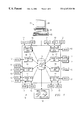
- FIG. 2 illustrates a block diagram of an exemplary operating unit 14 , according to an embodiment of the present invention.
- Operating unit 14 includes a number of servers 28 - 34 , each server comprising a software application, program, routine, process, or the like, which can be run or executed.
- Each server 28 - 34 can be either a primary server or a secondary server.
- Primary servers are distinguished from secondary servers in that primary servers cannot be shutdown or terminated whereas secondary servers can be.
- Each primary server may perform one or more specific functions, which can differ from the functions performed by other primary servers.
- Each secondary server corresponds to a particular primary server, and may perform many of the same functions as its corresponding primary server.
- a secondary server is invoked or added to operating unit 14 only when the corresponding primary server is “full,” as described herein.
- the primary servers in exemplary operating unit 14 include a primary rule server 28 and a plurality of primary device servers 32 .
- the secondary servers of operating unit 14 include a secondary rule server 30 and a plurality of secondary device servers 34 .
- primary rule server 28 secondary rule server 30 , primary device servers 32 , and secondary device servers 34 cooperate to manage, direct, instruct, or otherwise control the device or devices 12 to which operating unit 14 is coupled.
- primary rule server 28 , secondary rule server 30 , primary device servers 32 , and secondary device servers 34 may communicate with each other and the devices 12 which they control in the form of messages. These messages are passed between and among servers 28 - 34 , and are preferably composed of ASCII text.
- Each server 28 - 34 may include a corresponding “mailbox” (not explicitly shown) into which the messages are delivered.
- Each of primary rule server 28 , secondary rule server 30 , primary device servers 32 , and secondary device servers 34 has the capability to use an appropriate mailbox to command or request services of another server 28 - 34 .
- servers 28 - 34 may comprise intelligent object-oriented programs that generate and/or receive command messages.
- Primary rule server 28 comprises a set of rules for managing the operation of operating unit 14 .
- Primary rule server 28 performs logical operations to control and coordinate primary device servers 32 and secondary device servers 34 .
- Primary rule server 28 sends command messages to device servers 32 and 34 via the mailbox system, and may receive reply messages in response.
- Secondary rule server 30 is invoked or initiated when primary rule server 28 is “full.” Specifically, if primary rule server 28 has received a number of messages (in its corresponding mailbox) to which it must respond and is incapable of handling all of these messages, such as, for example, within a predetermined amount of time, primary rule server 28 invokes secondary rule server 30 to perform any “overflow” of functions or operations that are required.
- FIG. 2 shows a single secondary rule server 30 operating in exemplary operating unit 14 , it should be understood that no secondary rule server 30 would exist if primary rule server 28 was operating at less than “full” capacity.
- additional secondary rule servers 30 could be invoked and added to operating unit 14 if primary rule server 28 and all currently-existing secondary rule servers 30 are “full.”
- the present invention contemplates that up to a certain number of secondary rule servers 30 can be added for primary rule server 28 , after which additional secondary rule servers cannot be added. In one embodiment, up to four secondary rule servers 30 can be added for primary rule server 28 .
- Primary device servers 32 are coupled to primary rule server 28 and any existing secondary rule servers 30 . Each primary device server 32 may be coupled to and support one or more specific physical or logical devices 12 . Primary device servers 32 provide clearly understood functions to devices 12 . That is, each primary device server 32 is operable to perform one or more functional operations upon, or in response to, information that is received from the device(s) 12 which that primary device server 32 supports. Preferably, each primary device server 32 use command-oriented messages to instruct its associated device or devices 12 to perform various tasks. Exemplary device servers can be physical device servers and logical device servers. A physical device server manages or controls physical devices, such as robotic arms or scanners. A logical device server manages or controls logical devices, such as databases or processors.
- One or more corresponding secondary device servers 34 may be invoked for each primary device server 32 when that primary device server 32 is “full.”
- a corresponding secondary device server 34 is preferably added to operating unit 14 when its primary device server 32 and all currently-existing corresponding secondary device servers 34 for that primary server 32 are “full.”
- the present invention contemplates that up to a certain number of secondary device servers 34 can be added for each corresponding primary device server 32 . In one embodiment, up to four secondary device servers 34 can be added for a particular primary device server 32 .
- Each secondary device server 34 may provide much of the same functionality that is supported by its corresponding primary device server 32 .
- Each primary device server 32 and its corresponding secondary device servers 34 operate independently of the other primary device servers 32 and their corresponding secondary device servers 34 within operating unit 14 .
- Primary and secondary device servers 32 and 34 communicate with primary rule server 28 and any existing secondary rule server 30 to transmit information and receive controls, commands, or directions.
- Messages sent from a device server 32 , 34 to a rule server 28 , 30 may contain replies which are sent after the device server 32 , 34 processes a previously sent command.
- messages sent from a device server 32 , 34 to a rule server 28 , 30 can be unsolicited messages; the logic to handle this would be contained in a protected macro (as explained below).
- Each of primary rule server 28 , secondary rule server 30 , primary device servers 32 , and secondary device servers 34 is coupled to or communicates with memory 16 , which stores the software code 15 for servers 28 - 34 and one or more macros (shown in FIG. 3 ).
- Macros define or establish the functionality of servers 28 - 34 .
- Each macro can be used to perform one or more discrete tasks. Macros are logically segmented by function, and are called or invoked by servers 28 - 34 as needed during the operation of equipment control system 10 .
- Each of primary rule server 28 , secondary rule server 30 , primary device servers 32 , and secondary device servers 34 may utilize different macros to accomplish different purposes. In this manner, operating unit 14 , and accordingly, equipment control system 10 , achieves total control of devices 12 by implementing a distributed environment for performing various tasks.
- primary rule server 28 may initiate the running of various macros by primary and secondary device servers 32 and 34 in order to model the related functionality of devices 12 controlled by operating unit 14 . That is, different “threads” of macros may model the different functions of devices 12 .
- the macros within a thread are linked together so that as one macro finishes executing, the next macro it is linked to will begin executing.
- Macros may be either protected macros or unprotected macros.
- Protected macros reside or exist only within primary servers, such as primary rule server 28 or primary device servers 32 .
- a protected macro cannot be deleted or terminated from the primary server within which it resides.
- Unprotected macros may reside or exist within both primary servers, and also secondary servers, such as secondary rule server 30 and secondary device servers 34 .
- An unprotected macro can be deleted or terminated from the server within which it resides when its operation is no longer required.
- exemplary operating unit 14 will contain only primary servers, such as primary rule server 28 and primary device servers 32 .
- Each primary server will contain only one or more protected macros.
- unprotected macros are added to that primary server.
- a primary server becomes full with protected and unprotected macros (thus indicating that it is processing at its highest capacity)
- it will invoke or call a corresponding secondary server, such as secondary rule server 30 and secondary device server 34 .
- Unprotected macros are added to this secondary server to perform whatever functionality is desired or needed.
- additional secondary servers are invoked or called, and macros added.
- FIG. 3 illustrates a block diagram of an exemplary primary server 38 and corresponding secondary server 44 , according to an embodiment of the present invention.
- Primary server 38 and corresponding secondary server 44 can reside in an operating unit 14 .
- Primary server 38 may comprise a number of protected macros 40 and unprotected macros 42 .
- Each protected macro 40 may be executed to provide some functionality that is required of primary server 38 during operation of equipment control system 10 .
- the protected macros 40 contained within primary server 38 are operable to perform all functions which may be required of that primary server 38 .
- Protected macros 40 cannot be deleted or removed from primary server 38 if they are not being utilized or executed.
- Each unprotected macro 42 within primary server 38 corresponds to a specific protected macro 40 .
- unprotected macros 42 provide the same functionality as the protected macros 40 to which the unprotected macros 42 correspond.
- Unprotected macros 42 are invoked or called by primary server 38 in order to support additional processing if necessary to assist protected macros 40 .
- Each unprotected macro 42 can be deleted from primary server 38 when that unprotected macro 42 is no longer being utilized or executing.
- Primary server 38 may have the capacity to support up to a predetermined number of each unprotected macro 42 corresponding to a particular protected macro 40 . That is, for each protected macro 40 , primary server 38 may have a specific number of “slots” for the addition of corresponding unprotected macros 42 . For example, in one embodiment, up to four unprotected macros 42 can be added for a particular protected macro 40 in primary server 38 .
- Secondary server 44 is invoked when primary server 38 is busy or otherwise unavailable for processing.
- secondary server 44 comprises only unprotected macros 42 . These unprotected macros 42 are loaded into secondary server 44 as needed to provide some particular functionality that would otherwise be required from primary server 38 .
- each unprotected macro 42 within secondary server 44 may correspond to and support the same functions as a particular protected macro 40 contained in primary server 38 .
- secondary server 44 may comprise a predetermined number of slots into which unprotected macros 42 may be added. Because all macros within secondary server 44 are unprotected macros, these macros 42 can be deleted if their functionality is no longer required.
- Each protected macro 40 and unprotected macro 42 can be either a dynamic termination macro or a static termination macro.
- Dynamic termination macros terminate automatically. That is, a dynamic termination macro ceases to execute after each instance of performing the task or tasks for which it was designed.
- a static termination macro must be specifically instructed to terminate; otherwise, it will continue to execute or run.
- a static termination macro will continue to process any request that it receives.
- a static termination macro cannot be shutdown while it is actually processing.
- primary server 38 monitors itself and any corresponding secondary servers 44 .
- the primary server 38 may issue a command to load an unprotected macro corresponding to a function which is in demand.
- the primary server 38 loads the called unprotected macro into the first server (either primary server 38 or a corresponding secondary server 44 ) with a slot available for that type of macro. If there are no available slots in any existing server, primary server 38 invokes or calls another secondary server 44 , into which the necessary macro is loaded.
- Primary server 38 may also shut down secondary servers 44 and delete unprotected macros. However, primary server 38 cannot shut itself down, nor can it delete a protected macro.
- scalability is controlled by the primary server.
- Handshaking is used between the primary server 38 and its corresponding secondary servers 44 to track the status of currently existing servers.
- Each of primary server 38 and secondary server 44 tracks the status of the protected macros 40 (if any) and unprotected macros 42 loaded in that server. Updates of a server's status are sent to primary server 38 as status changes.
- handshaking occurs between a server 38 , 44 and its loaded macros 40 , 42 to provide a shutdown without interrupting any current processing.
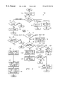
- FIG. 4 is a flow chart of an exemplary method 100 for optimizing the operation of equipment control system 10 , according to an embodiment of the present invention.
- Method 100 may correspond to the operation of a primary server, such as, for example, primary rule server 28 or a primary device server 32 shown in FIG. 2 .
- Method 100 begins at step 102 where a message is received in the mailbox for the primary server.
- Each message that may be received by the primary server at step 102 can be generated by the primary server itself or a corresponding secondary server.
- the primary server determines what kind of condition has triggered the request.
- An exemplary flow chart for such an “add entity” sub-routine is illustrated and described below in more detail with reference to FIG. 5 .
- a condition of “server is empty” indicates that either the primary server or one of its corresponding secondary servers is not currently processing, performing, or otherwise executing. In other words, all macros within such server generating the message have ceased to run.
- a “server is in timeout” condition indicates that processing has ceased on the server generating the message.
- such message can be generated by a macro contained in any of a rule server, a logical device server, or a physical device server.
- the primary server determines what type of server generated the message.
- the primary server generating the message is a logical device server
- the primary server identifies such logical device server so that a macro can be deleted if desired.
- the primary server determines whether the macro is protected. If the macro is protected, it should not be deleted, and, accordingly, the primary server disables the “timeout” for that type of macro at step 120 . Method 100 then ends. Otherwise, if the macro is not protected, then the primary server “kills” or shuts down the macro at step 122 , thereby causing the associated software code 15 to be deleted from memory 16 .
- this secondary server is disconnected from the mailbox of the primary server.
- This secondary server then sends a shutdown command to all macros contained within that server at step 134 .
- the shutdown command causes the software code 15 supporting these macros to be deleted from memory 16 .
- the primary server sends a shutdown command to the secondary server which was loaded last.
- this secondary server sends a shutdown to all of the macros contained within that server, thereby causing the macros to shutdown and deleting the associated software code 15 for such macros from memory 16 .
- servers and macros are added to and deleted from an operating unit 14 as necessary to accomplish the functionality required of equipment control system 10 during its operation.
- This addition and deletion of servers and macros causes associated software code 15 to be copied into and removed from memory 16 .
- the operation of equipment control system 10 is optimized because only the software code 15 that is needed to provide functionality at any given moment will be contained in memory 16 at such time.
- FIG. 5 is a flow chart of an exemplary method 200 for adding an operating entity, such as, for example, a secondary server or an unprotected macro, to provide additional functionality in equipment control system 10 , according to an embodiment of the present invention.
- Method 200 may be performed by a primary server and invoked when additional functionality is required of that primary server and/or its corresponding secondary servers in existence at that time.
- method 200 may correspond to step 108 of method 100 shown in FIG. 4, and accordingly, can be performed as a sub-routine of method 100 .
- Method 200 begins at step 202 where it is determined whether any servers, either the primary server or a corresponding secondary server, are active. A server is “active” if it is currently loaded and running; a server is “inactive” if it is not currently loaded and not currently running, but is available to be loaded. If no servers are active, then a server is started at step 204 . Method 200 then moves to step 206 .
- step 202 determines whether at least one server is active. If it is determined at step 202 that at least one server is active, then method 200 moves directly to step 206 where the primary server scans the next active server (i.e., the server that was loaded or started first) for available macro space.
- the primary server scans the next active server (i.e., the server that was loaded or started first) for available macro space.
- the primary server determines whether there is any “space” to support an appropriate macro in the active server that was scanned. That is, the primary server determines if the scanned server has any “slots” available for the addition of a macro that performs the functions which are being requested at the current moment. If there is space in the active server, then at step 210 the primary server adds the appropriate macro for the desired functionality to that server.
- the primary server determines whether there are any other active servers. If there are more active servers, the primary server returns to step 206 where it scans the next active server for available macro space. The primary server may perform steps 206 - 216 until an appropriate macro has been added to a server with available macro space or until there are no active servers left to be scanned.
- the primary server determines whether the maximum number of servers have been loaded. If the maximum number of servers have not been loaded, the primary server starts another server at step 204 .
- an initial alarm is sent at step 220 .
- the primary server waits for the occurrence of a timeout in any active server, the deletion of a macro from any active server, or the deletion of a server.
- the deletion of a macro from an existing server or the deletion of a server indicates that space is now available for adding the desired macro.
- a timeout occurs when any macros on any existing server has ceased processing.
- the primary server determines whether a timeout has occurred at step 224 . If a timeout has occurred, the primary server sends another alarm at step 226 . After the alarm is sent, method 200 ends.
- step 228 the primary server determines whether a macro or a server has been deleted. If neither a macro nor a server has been deleted, then the primary server returns to step 222 where it waits for a timeout or the deletion of a macro or server. Otherwise, if it is determined at step 228 that a macro or a server has been deleted, then method 200 returns to step 202 where the primary server determines whether there are any active servers.
- FIG. 6 is a flow chart of an exemplary method 300 for executing a dynamic termination macro, according to an embodiment of the present invention.
- a dynamic termination macro is a protected or unprotected macro which terminates automatically after it has run.
- Method 300 may be performed for each dynamic termination macro when its functionality is required.
- Method 300 begins at step 302 where a primary server determines whether such a dynamic termination macro should be added or if the macro already exists. If the macro should be added, the primary server adds the dynamic termination macro at step 304 , after which method 300 moves to step 306 . If the macro already exists, then method 300 proceeds directly to step 306 .
- the dynamic termination macro begins execution—i.e., the macro is run.
- the dynamic termination macro initializes at step 308 .
- Processes for the dynamic termination macro are executed at step 310 . Essentially, this step comprises the performance of the function for which the dynamic termination macro is designed or provided. After the processes have executed, the dynamic termination macro terminates automatically. A clean-up for the dynamic termination macro is performed at step 312 .
- the primary server determines whether the dynamic termination macro should be deleted. If the macro should not be deleted, then the dynamic termination type macro is reset at step 316 , after which method 300 ends. Otherwise, if the dynamic termination macro should be deleted, then at step 318 this macro is deleted, thereby causing the software code 15 supporting such macro to be removed from memory 16 . Method 300 then ends.
- FIG. 7 is a flow chart of a method 400 for deleting a dynamic termination macro, according to an embodiment of the present invention.
- Method 400 may be performed by a primary server upon a dynamic termination macro residing within that primary server or a corresponding secondary server.
- Method 400 begins at step 402 , where the primary server determines whether the dynamic termination macro is protected. If the macro is protected, it should not be deleted, and, accordingly, method 400 ends. Otherwise, if the dynamic termination macro is not protected, then at step 404 the primary server deletes the macro from the server within which the macro resides. This causes the software code 15 supporting such macro to be removed from memory 16 .
- the server within which the deleted macro previously resided is not a primary server, then, by default, such server is a secondary server.
- the primary server shuts down the empty secondary server, after which method 400 ends.
- FIG. 8 is a flow chart of a method 500 for executing a static termination macro, according to an embodiment of the present invention.
- a static termination macro is a protected or unprotected macro which runs continuously until it is specifically instructed to terminate. Method 500 may be performed for each static termination macro.
- Method 500 begins at step 502 where the static termination macro is added to either a primary server or a secondary server. At step 504 , the static termination macro begins to execute or run. At this point, method 500 diverges into two parallel flows of processing.
- the static termination macro initializes at step 516 .
- a message can be received in a mailbox associated with the static termination macro.
- processes for the static termination macro are executed at step 520 .
- the static termination macro performs the functionality for which it was designed or provided.
- the static termination macro determines whether its external status equals shutdown (i.e., the macro has been specifically instructed to shutdown by the server). If the external status of the macro does not equal shutdown, the macro returns to step 518 where it waits to receive a message in its associated mailbox. However, if at step 522 it is determined that the external status of the macro equals shutdown, a macro clean-up is performed at step 524 .
- Method 500 then moves to step 514 where the static termination macro is deleted, after which method 500 ends.
- the static termination macro waits for the receipt of a shutdown instruction at step 506 .
- a macro clean-up is performed at step 510 .
- step 512 there is a break in the execution of the static termination macro.
- step 514 the static termination macro is deleted, thereby causing the software code 15 supporting such macro to be removed from memory 16 .
- Method 500 then ends.
- FIG. 9 is a flow chart of a method 600 for deleting a static termination macro according to an embodiment of the present invention.
- Method 600 may be performed by a primary server operating upon a static termination macro which is contained within that primary server or a corresponding secondary server.
- Method 600 begins at step 602 , where the primary server determines whether the static termination macro is protected. If the static termination type macro is protected, it should not be deleted, and, accordingly, method 600 ends. Otherwise, if the macro is not protected, the primary server deactivates the static termination macro at step 604 .
- the primary server determines whether the static termination macro is currently running or executing processes. If the macro is currently running, then at step 608 the primary server waits for the static termination macro to terminate, after which the primary server moves to step 610 . Otherwise, if the static termination macro is not currently running, then method 600 moves directly to step 610 . At step 610 the primary server breaks out of the static termination macro and, at step 612 the primary server deletes the static termination macro. The deletion of the static termination macro causes the software code 15 supporting such macro to be removed from memory 16 .
Abstract
Description
Claims (16)
Priority Applications (1)
| Application Number | Priority Date | Filing Date | Title |
|---|---|---|---|
| US09/337,098 US6347328B1 (en) | 1997-04-14 | 1999-06-21 | Optimizing the operation of an equipment control system using one or more servers |
Applications Claiming Priority (2)
| Application Number | Priority Date | Filing Date | Title |
|---|---|---|---|
| US08/837,955 US5997168A (en) | 1997-04-14 | 1997-04-14 | Optimizing the operation of an equipment control system |
| US09/337,098 US6347328B1 (en) | 1997-04-14 | 1999-06-21 | Optimizing the operation of an equipment control system using one or more servers |
Related Parent Applications (1)
| Application Number | Title | Priority Date | Filing Date |
|---|---|---|---|
| US08/837,955 Division US5997168A (en) | 1997-04-14 | 1997-04-14 | Optimizing the operation of an equipment control system |
Publications (1)
| Publication Number | Publication Date |
|---|---|
| US6347328B1 true US6347328B1 (en) | 2002-02-12 |
Family
ID=25275880
Family Applications (2)
| Application Number | Title | Priority Date | Filing Date |
|---|---|---|---|
| US08/837,955 Expired - Fee Related US5997168A (en) | 1997-04-14 | 1997-04-14 | Optimizing the operation of an equipment control system |
| US09/337,098 Expired - Fee Related US6347328B1 (en) | 1997-04-14 | 1999-06-21 | Optimizing the operation of an equipment control system using one or more servers |
Family Applications Before (1)
| Application Number | Title | Priority Date | Filing Date |
|---|---|---|---|
| US08/837,955 Expired - Fee Related US5997168A (en) | 1997-04-14 | 1997-04-14 | Optimizing the operation of an equipment control system |
Country Status (1)
| Country | Link |
|---|---|
| US (2) | US5997168A (en) |
Cited By (10)
| Publication number | Priority date | Publication date | Assignee | Title |
|---|---|---|---|---|
| US20030051021A1 (en) * | 2001-09-05 | 2003-03-13 | Hirschfeld Robert A. | Virtualized logical server cloud |
| US6675199B1 (en) * | 2000-07-06 | 2004-01-06 | Microsoft | Identification of active server cluster controller |
| US20040210636A1 (en) * | 2000-07-06 | 2004-10-21 | Microsoft Corporation | Load balancing of chat servers based on gradients |
| US7099933B1 (en) * | 2000-07-11 | 2006-08-29 | Nortel Networks Limited | System and method for regulating web site access |
| US20100281181A1 (en) * | 2003-09-26 | 2010-11-04 | Surgient, Inc. | Network abstraction and isolation layer for masquerading machine identity of a computer |
| US20110131580A1 (en) * | 2009-11-30 | 2011-06-02 | International Business Machines Corporation | Managing task execution on accelerators |
| US20110131430A1 (en) * | 2009-11-30 | 2011-06-02 | International Business Machines Corporation | Managing accelerators of a computing environment |
| US8078728B1 (en) | 2006-03-31 | 2011-12-13 | Quest Software, Inc. | Capacity pooling for application reservation and delivery |
| US8194674B1 (en) | 2007-12-20 | 2012-06-05 | Quest Software, Inc. | System and method for aggregating communications and for translating between overlapping internal network addresses and unique external network addresses |
| US20160342195A1 (en) * | 2008-06-24 | 2016-11-24 | Virident Systems, Inc. | Network computer systems with power management |
Families Citing this family (8)
| Publication number | Priority date | Publication date | Assignee | Title |
|---|---|---|---|---|
| US6237053B1 (en) | 1998-06-30 | 2001-05-22 | Symbol Technologies, Inc. | Configurable operating system having multiple data conversion applications for I/O connectivity |
| US7206849B1 (en) | 1998-10-05 | 2007-04-17 | Symbol Technologies, Inc. | Communication in a wireless communications network when a mobile computer terminal may be unreachable |
| US6811085B2 (en) * | 2001-10-26 | 2004-11-02 | Symbol Technologies, Inc. | Miniature imager |
| US7025822B2 (en) * | 2004-04-28 | 2006-04-11 | Sierra Process Systems, Inc. | Asphalt mastic utilizing petroleum refinery waste solids |
| US20060109117A1 (en) * | 2004-11-22 | 2006-05-25 | International Business Machines Corporation | Apparatus and Method of Intelligent Multistage System Deactivation |
| US20060165543A1 (en) * | 2005-01-24 | 2006-07-27 | York International Corporation | Screw compressor acoustic resonance reduction |
| US10530725B2 (en) * | 2015-03-09 | 2020-01-07 | Microsoft Technology Licensing, Llc | Architecture for large data management in communication applications through multiple mailboxes |
| US10530724B2 (en) * | 2015-03-09 | 2020-01-07 | Microsoft Technology Licensing, Llc | Large data management in communication applications through multiple mailboxes |
Citations (5)
| Publication number | Priority date | Publication date | Assignee | Title |
|---|---|---|---|---|
| US4403286A (en) * | 1981-03-06 | 1983-09-06 | International Business Machines Corporation | Balancing data-processing work loads |
| US4947315A (en) | 1986-12-03 | 1990-08-07 | Finnigan Corporation | System for controlling instrument using a levels data structure and concurrently running compiler task and operator task |
| US5280585A (en) | 1990-09-28 | 1994-01-18 | Hewlett-Packard Company | Device sharing system using PCL macros |
| US5764958A (en) | 1995-11-30 | 1998-06-09 | International Business Machines Corporation | Method and apparatus for creating dynamic roles with a system object model |
| US5784622A (en) * | 1992-11-18 | 1998-07-21 | Canon Kabushiki Kaisha | Method and apparatus for multiprotocol operation of a networked peripheral |
-
1997
- 1997-04-14 US US08/837,955 patent/US5997168A/en not_active Expired - Fee Related
-
1999
- 1999-06-21 US US09/337,098 patent/US6347328B1/en not_active Expired - Fee Related
Patent Citations (5)
| Publication number | Priority date | Publication date | Assignee | Title |
|---|---|---|---|---|
| US4403286A (en) * | 1981-03-06 | 1983-09-06 | International Business Machines Corporation | Balancing data-processing work loads |
| US4947315A (en) | 1986-12-03 | 1990-08-07 | Finnigan Corporation | System for controlling instrument using a levels data structure and concurrently running compiler task and operator task |
| US5280585A (en) | 1990-09-28 | 1994-01-18 | Hewlett-Packard Company | Device sharing system using PCL macros |
| US5784622A (en) * | 1992-11-18 | 1998-07-21 | Canon Kabushiki Kaisha | Method and apparatus for multiprotocol operation of a networked peripheral |
| US5764958A (en) | 1995-11-30 | 1998-06-09 | International Business Machines Corporation | Method and apparatus for creating dynamic roles with a system object model |
Non-Patent Citations (4)
| Title |
|---|
| "Distributed Message Passing System", FASTech Integration, INForm MBX Commands, Nov. 1996, pp. 2-12 to 2-17. |
| "Introduction to CELLworks-Students's Manual-Sections 1-4", FASTech Integration, dated Jul. 1994, pp. 1.1.5, 1.1.10, and 1.1.13. |
| "Introduction-CELLworks-4 Architectural Overview", FASTech Integration, dated Aug. 1993, pp. 1-1 to 1-4 and 3-1 to 3-2. |
| "Introduction—CELLworks-4 Architectural Overview", FASTech Integration, dated Aug. 1993, pp. 1-1 to 1-4 and 3-1 to 3-2. |
Cited By (16)
| Publication number | Priority date | Publication date | Assignee | Title |
|---|---|---|---|---|
| US6675199B1 (en) * | 2000-07-06 | 2004-01-06 | Microsoft | Identification of active server cluster controller |
| US20040210636A1 (en) * | 2000-07-06 | 2004-10-21 | Microsoft Corporation | Load balancing of chat servers based on gradients |
| US7310802B2 (en) | 2000-07-06 | 2007-12-18 | Microsoft Corporation | Load balancing of chat servers based on gradients |
| US7099933B1 (en) * | 2000-07-11 | 2006-08-29 | Nortel Networks Limited | System and method for regulating web site access |
| US6880002B2 (en) * | 2001-09-05 | 2005-04-12 | Surgient, Inc. | Virtualized logical server cloud providing non-deterministic allocation of logical attributes of logical servers to physical resources |
| US20030051021A1 (en) * | 2001-09-05 | 2003-03-13 | Hirschfeld Robert A. | Virtualized logical server cloud |
| US20100281181A1 (en) * | 2003-09-26 | 2010-11-04 | Surgient, Inc. | Network abstraction and isolation layer for masquerading machine identity of a computer |
| US8331391B2 (en) | 2003-09-26 | 2012-12-11 | Quest Software, Inc. | Network abstraction and isolation layer for masquerading machine identity of a computer |
| US8078728B1 (en) | 2006-03-31 | 2011-12-13 | Quest Software, Inc. | Capacity pooling for application reservation and delivery |
| US8194674B1 (en) | 2007-12-20 | 2012-06-05 | Quest Software, Inc. | System and method for aggregating communications and for translating between overlapping internal network addresses and unique external network addresses |
| US20160342195A1 (en) * | 2008-06-24 | 2016-11-24 | Virident Systems, Inc. | Network computer systems with power management |
| US10156890B2 (en) * | 2008-06-24 | 2018-12-18 | Virident Systems, Llc | Network computer systems with power management |
| US20110131430A1 (en) * | 2009-11-30 | 2011-06-02 | International Business Machines Corporation | Managing accelerators of a computing environment |
| US8776066B2 (en) | 2009-11-30 | 2014-07-08 | International Business Machines Corporation | Managing task execution on accelerators |
| US8423799B2 (en) * | 2009-11-30 | 2013-04-16 | International Business Machines Corporation | Managing accelerators of a computing environment |
| US20110131580A1 (en) * | 2009-11-30 | 2011-06-02 | International Business Machines Corporation | Managing task execution on accelerators |
Also Published As
| Publication number | Publication date |
|---|---|
| US5997168A (en) | 1999-12-07 |
Similar Documents
| Publication | Publication Date | Title |
|---|---|---|
| US6347328B1 (en) | Optimizing the operation of an equipment control system using one or more servers | |
| US6961926B2 (en) | System and method for distributed debugging and recording medium on which control programs are recorded | |
| EP0554611B1 (en) | Spooler for barcode printers | |
| US6154787A (en) | Grouping shared resources into one or more pools and automatically re-assigning shared resources from where they are not currently needed to where they are needed | |
| US5991792A (en) | Method, apparatus and computer program product for dynamically managing a thread pool of reusable threads in a computer system | |
| US7047484B1 (en) | Method, system, and apparatus for providing access to asynchronous data in a spreadsheet application program | |
| US4731750A (en) | Workstation resource sharing | |
| JPH01241631A (en) | Interruption and restarting of task processing for virtual computer data processing system | |
| US6542904B2 (en) | Method and system for efficiently providing maintenance activity on a relational database that is utilized within a processing system | |
| WO1997042568A9 (en) | Seamless application interface manager | |
| WO1997042568A1 (en) | Seamless application interface manager | |
| US5684992A (en) | User console and computer operating system asynchronous interaction interface | |
| US5226176A (en) | System for selectively aborting operation or waiting to load required data based upon user response to non-availability of network load device | |
| US5511194A (en) | Processing system and processing method capable of dynamically replacing job environment | |
| US6078933A (en) | Method and apparatus for parallel processing for archiving and retrieval of data | |
| EP2038714B1 (en) | Method, computer readable medium and system for guaranteed batch event delivery in a process control system | |
| JPH08221433A (en) | Information retrieval system | |
| US20040025007A1 (en) | Restricting access to a method in a component | |
| US7346910B1 (en) | Administration of groups of computer programs, data processing systems, or system resources | |
| CN111147282B (en) | Device, method and storage medium for automatically maintaining DRCP connection pool | |
| JP3738701B2 (en) | System setting method in transaction processing system | |
| JPS635780B2 (en) | ||
| US5745690A (en) | Data processing system and method | |
| JPH04113421A (en) | Initial program loading system | |
| JP2580970B2 (en) | Control method of calling process by schedule start |
Legal Events
| Date | Code | Title | Description |
|---|---|---|---|
| AS | Assignment |
Owner name: ELECTRONIC DATA SYSTEMS CORPORATION, TEXAS Free format text: ASSIGNMENT OF ASSIGNORS INTEREST;ASSIGNORS:HARPER, JEFFREY G.;ZUSTOVICH, BRAIN F.;REEL/FRAME:010049/0594 Effective date: 19970408 |
|
| FPAY | Fee payment |
Year of fee payment: 4 |
|
| AS | Assignment |
Owner name: ELECTRONIC DATA SYSTEMS, LLC, DELAWARE Free format text: CHANGE OF NAME;ASSIGNOR:ELECTRONIC DATA SYSTEMS CORPORATION;REEL/FRAME:022460/0948 Effective date: 20080829 Owner name: ELECTRONIC DATA SYSTEMS, LLC,DELAWARE Free format text: CHANGE OF NAME;ASSIGNOR:ELECTRONIC DATA SYSTEMS CORPORATION;REEL/FRAME:022460/0948 Effective date: 20080829 |
|
| AS | Assignment |
Owner name: HEWLETT-PACKARD DEVELOPMENT COMPANY, L.P., TEXAS Free format text: ASSIGNMENT OF ASSIGNORS INTEREST;ASSIGNOR:ELECTRONIC DATA SYSTEMS, LLC;REEL/FRAME:022449/0267 Effective date: 20090319 Owner name: HEWLETT-PACKARD DEVELOPMENT COMPANY, L.P.,TEXAS Free format text: ASSIGNMENT OF ASSIGNORS INTEREST;ASSIGNOR:ELECTRONIC DATA SYSTEMS, LLC;REEL/FRAME:022449/0267 Effective date: 20090319 |
|
| FPAY | Fee payment |
Year of fee payment: 8 |
|
| FEPP | Fee payment procedure |
Free format text: PAYOR NUMBER ASSIGNED (ORIGINAL EVENT CODE: ASPN); ENTITY STATUS OF PATENT OWNER: LARGE ENTITY |
|
| REMI | Maintenance fee reminder mailed | ||
| LAPS | Lapse for failure to pay maintenance fees | ||
| STCH | Information on status: patent discontinuation |
Free format text: PATENT EXPIRED DUE TO NONPAYMENT OF MAINTENANCE FEES UNDER 37 CFR 1.362 |
|
| FP | Lapsed due to failure to pay maintenance fee |
Effective date: 20140212 |