US6359906B1 - Providing digital services to telephone subscribers - Google Patents
Providing digital services to telephone subscribers Download PDFInfo
- Publication number
- US6359906B1 US6359906B1 US09/028,540 US2854098A US6359906B1 US 6359906 B1 US6359906 B1 US 6359906B1 US 2854098 A US2854098 A US 2854098A US 6359906 B1 US6359906 B1 US 6359906B1
- Authority
- US
- United States
- Prior art keywords
- service
- subscriber
- line card
- subscribers
- adsl
- Prior art date
- Legal status (The legal status is an assumption and is not a legal conclusion. Google has not performed a legal analysis and makes no representation as to the accuracy of the status listed.)
- Expired - Lifetime
Links
Images


Classifications
-
- H—ELECTRICITY
- H04—ELECTRIC COMMUNICATION TECHNIQUE
- H04L—TRANSMISSION OF DIGITAL INFORMATION, e.g. TELEGRAPHIC COMMUNICATION
- H04L12/00—Data switching networks
- H04L12/28—Data switching networks characterised by path configuration, e.g. LAN [Local Area Networks] or WAN [Wide Area Networks]
- H04L12/2854—Wide area networks, e.g. public data networks
- H04L12/2856—Access arrangements, e.g. Internet access
- H04L12/2869—Operational details of access network equipments
- H04L12/2878—Access multiplexer, e.g. DSLAM
- H04L12/2887—Access multiplexer, e.g. DSLAM characterised by the offered subscriber services
- H04L12/2889—Multiservice, e.g. MSAN
-
- H—ELECTRICITY
- H04—ELECTRIC COMMUNICATION TECHNIQUE
- H04J—MULTIPLEX COMMUNICATION
- H04J1/00—Frequency-division multiplex systems
- H04J1/02—Details
- H04J1/12—Arrangements for reducing cross-talk between channels
-
- H—ELECTRICITY
- H04—ELECTRIC COMMUNICATION TECHNIQUE
- H04L—TRANSMISSION OF DIGITAL INFORMATION, e.g. TELEGRAPHIC COMMUNICATION
- H04L12/00—Data switching networks
- H04L12/28—Data switching networks characterised by path configuration, e.g. LAN [Local Area Networks] or WAN [Wide Area Networks]
- H04L12/2854—Wide area networks, e.g. public data networks
- H04L12/2856—Access arrangements, e.g. Internet access
-
- H—ELECTRICITY
- H04—ELECTRIC COMMUNICATION TECHNIQUE
- H04L—TRANSMISSION OF DIGITAL INFORMATION, e.g. TELEGRAPHIC COMMUNICATION
- H04L5/00—Arrangements affording multiple use of the transmission path
- H04L5/02—Channels characterised by the type of signal
- H04L5/023—Multiplexing of multicarrier modulation signals
-
- H—ELECTRICITY
- H04—ELECTRIC COMMUNICATION TECHNIQUE
- H04L—TRANSMISSION OF DIGITAL INFORMATION, e.g. TELEGRAPHIC COMMUNICATION
- H04L5/00—Arrangements affording multiple use of the transmission path
- H04L5/14—Two-way operation using the same type of signal, i.e. duplex
- H04L5/143—Two-way operation using the same type of signal, i.e. duplex for modulated signals
-
- H—ELECTRICITY
- H04—ELECTRIC COMMUNICATION TECHNIQUE
- H04M—TELEPHONIC COMMUNICATION
- H04M11/00—Telephonic communication systems specially adapted for combination with other electrical systems
- H04M11/06—Simultaneous speech and data transmission, e.g. telegraphic transmission over the same conductors
- H04M11/062—Simultaneous speech and data transmission, e.g. telegraphic transmission over the same conductors using different frequency bands for speech and other data
-
- H—ELECTRICITY
- H04—ELECTRIC COMMUNICATION TECHNIQUE
- H04M—TELEPHONIC COMMUNICATION
- H04M3/00—Automatic or semi-automatic exchanges
- H04M3/005—Interface circuits for subscriber lines
- H04M3/007—Access interface units for simultaneous transmission of speech and data, e.g. digital subscriber line [DSL] access interface units
-
- H—ELECTRICITY
- H04—ELECTRIC COMMUNICATION TECHNIQUE
- H04Q—SELECTING
- H04Q11/00—Selecting arrangements for multiplex systems
- H04Q11/04—Selecting arrangements for multiplex systems for time-division multiplexing
-
- H—ELECTRICITY
- H04—ELECTRIC COMMUNICATION TECHNIQUE
- H04Q—SELECTING
- H04Q1/00—Details of selecting apparatus or arrangements
- H04Q1/02—Constructional details
- H04Q1/14—Distribution frames
-
- H—ELECTRICITY
- H04—ELECTRIC COMMUNICATION TECHNIQUE
- H04Q—SELECTING
- H04Q2213/00—Indexing scheme relating to selecting arrangements in general and for multiplex systems
- H04Q2213/13039—Asymmetrical two-way transmission, e.g. ADSL, HDSL
-
- H—ELECTRICITY
- H04—ELECTRIC COMMUNICATION TECHNIQUE
- H04Q—SELECTING
- H04Q2213/00—Indexing scheme relating to selecting arrangements in general and for multiplex systems
- H04Q2213/13076—Distributing frame, MDF, cross-connect switch
-
- H—ELECTRICITY
- H04—ELECTRIC COMMUNICATION TECHNIQUE
- H04Q—SELECTING
- H04Q2213/00—Indexing scheme relating to selecting arrangements in general and for multiplex systems
- H04Q2213/1309—Apparatus individually associated with a subscriber line, line circuits
-
- H—ELECTRICITY
- H04—ELECTRIC COMMUNICATION TECHNIQUE
- H04Q—SELECTING
- H04Q2213/00—Indexing scheme relating to selecting arrangements in general and for multiplex systems
- H04Q2213/13099—Loop multiplexer
-
- H—ELECTRICITY
- H04—ELECTRIC COMMUNICATION TECHNIQUE
- H04Q—SELECTING
- H04Q2213/00—Indexing scheme relating to selecting arrangements in general and for multiplex systems
- H04Q2213/1319—Amplifier, attenuation circuit, echo suppressor
-
- H—ELECTRICITY
- H04—ELECTRIC COMMUNICATION TECHNIQUE
- H04Q—SELECTING
- H04Q2213/00—Indexing scheme relating to selecting arrangements in general and for multiplex systems
- H04Q2213/13298—Local loop systems, access network
-
- H—ELECTRICITY
- H04—ELECTRIC COMMUNICATION TECHNIQUE
- H04Q—SELECTING
- H04Q2213/00—Indexing scheme relating to selecting arrangements in general and for multiplex systems
- H04Q2213/13305—Transistors, semiconductors in general
-
- H—ELECTRICITY
- H04—ELECTRIC COMMUNICATION TECHNIQUE
- H04Q—SELECTING
- H04Q2213/00—Indexing scheme relating to selecting arrangements in general and for multiplex systems
- H04Q2213/13381—Pair-gain system, digital loop carriers
Definitions
- This invention relates to arrangements and methods for providing digital services to telephone subscribers via the subscriber loop.
- twisted conductor pairs In a conventional telephone system, the majority of subscribers are connected to local exchanges via twisted conductor pairs, generally referred to as subscriber loops. Between the subscribers and the exchange, the subscriber loops are carried in cables each containing a large number of conductor pairs. The cables issuing from the exchange feed smaller street cables from which the individual subscriber loops are ‘dropped’ to provide the final link to the subscriber.
- These twisted pair subscriber loops were originally installed to carry voice services, but are now being used by the system operators to carry digital services such as ADSL (asymmetric digital subscriber line) in the frequency spectrum above the baseband frequencies used for the voice or POTS (plain ordinary telephone service) traffic.
- ADSL asymmetric digital subscriber line
- POTS plain ordinary telephone service
- a duplex service such as ADSL is launched on to the subscriber loop at each end and may carry e.g. video and/or Internet traffic to the subscriber.
- the currently employed ADSL service is a broad band technology which occupies a frequency band above that of voice to provide high bit rate (asymmetric) services to customers.
- this service uses discrete multi-tone technology (DMT) at frequencies from as low as 26 kHz up to about 1.1 MHz at a downstream bit rate of 2 Mb/s or multiples thereof. For example, bit rates of 6 Mb/s may be used over short distances.
- DMT discrete multi-tone technology
- bit rates of 6 Mb/s may be used over short distances.
- a particular concern of service providers is the freedom to introduce new digital services that do not destabilise existing services and can operate in parallel with those services that are currently in use.
- VDSL very high bit rate digital subscriber line
- a further object of the invention is to provide an improved arrangement and method for the delivery of digital services to a telephone subscriber.
- a further object of the invention is to provide an arrangement and method for providing ADSL and VDSL services to telecommunications customers via a common exchange or switch.
- a local telecommunications network system arranged to provide first and second services in respective first and second frequency bands to system subscribers, the system comprising an exchange or switch to which the subscribers are coupled each via a respective subscriber loop, means for applying said first service to selected subscriber loops, means for applying said second service to other selected subscriber loops, first filter means associated with said selected subscriber loops, and second filter means associated with said other subscriber loops, wherein each said filter means is arranged to provide a band edge cut-off of its respective first or second frequency band so as to inhibit interference of service-carrying signals between said first and second frequency bands.
- a local telecommunications network system arranged to provide a first asymmetric digital subscriber line (ADSL) service in a first frequency band to a first set of subscribers and a second very high bit rate digital subscriber line (VDSL) service in a second frequency band higher than said first frequency band to a second set of subscribers, the system comprising an exchange or switch to which the subscribers are coupled each via a respective subscriber loop, first line card means for applying said ADSL service to selected subscriber loops, second line card means for applying said VDSL service to other selected subscriber loops, first low-pass filter means associated with said first line card means, and second high-pass filter means associated with said second line card means, wherein each said filter means is arranged to provide a band edge cut-off of its respective first or second frequency band so as to inhibit interference of service-carrying signals between said first and second frequency bands.
- ADSL asymmetric digital subscriber line
- VDSL very high bit rate digital subscriber line
- a local telecommunications network system arranged to provide a first asymmetric digital subscriber line (ADSL) service in a first frequency band to a first set of subscribers and a second very high bit rate digital subscriber line (VDSL) service in a second frequency band higher than said first frequency band to a second set of subscribers, the system comprising an exchange or switch to which the subscribers are coupled each via a respective subscriber loop, first line card means for applying said ADSL service to selected subscriber loops, second line card means for applying said VDSL service to other selected subscriber loops, a main distribution frame associated with the exchange and whereby each subscriber loop is coupled to its respective line card means, each said subscriber loop having said ADSL service being further coupled via a POTS splitter and the main distribution frame to a further telephony line card, first low pass filter means associated with said first line card means, and second high pass filter means associated with said second line card means, wherein each said filter means is arranged to provide a band edge cut-
- ADSL asymmetric digital subscriber line
- a method of providing first and second services in respective first and second frequency bands to subscribers in a local telecommunications network system comprising an exchange or switch to which the subscribers are coupled each via a respective subscriber loop, first line card means for applying said first service to selected subscriber loops, second line card means for applying said second service to other selected subscriber loops, the method comprising low pass filtering traffic on subscriber loops carrying said first service, and high pass filtering traffic on subscriber loops carrying said second service so as to inhibit interference of service-carrying signals between said first and second frequency bands.
- the low pass and high-pass filters may comprise balanced-T inductor/capacitor circuits.
- the low pass and high pass filtering can be applied via a notch filter of common design.
- the filtering is applied to the subscriber line card at the exchange.
- FIG. 1 is a schematic diagram of a telecommunications network providing ADSL and VDSL services to subscribers;
- FIG. 2 is a frequency spectrum diagram illustrating the band occupancy of ADSL and VDSL services
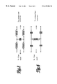
- FIG. 3 illustrates a low-pass filter construction for use in the network of FIG. 1;
- FIG. 4 illustrates a high-pass filter construction for use in the network of FIG. 1;
- FIG. 5 illustrates in schematic form a notch filter construction for use in the network of FIG. 1;
- FIG. 6 shows a typical frequency characteristic of a single or composite filter arrangement employed in the network of FIG. 1;
- FIG. 7 illustrates the relationship between impedance and frequency for the filter of FIG. 5.
- FIG. 8 shows an alternative filter characteristic that may be employed in the network of FIG. 1 .
- FIG. 1 shows in schematic form a local telecommunications network in which subscriber terminals 11 are served from a local exchange generally indicated as 12 each via a respective subscriber loop 13 .
- each subscriber loop or line 13 comprises a twisted pair of wire conductors.
- some subscribers receive simply a telephone or POTS service.
- Other subscribers generally residential or small business, receive an ADSL service in addition to their POTS service, while yet other subscribers, generally medium or large business, receive a VDSL service.
- FIG. 1 shows only those parts of the exchange necessary for the understanding of the invention are depicted in FIG. 1, and in particular the switch associated with the exchange is not shown.
- the exchange 12 comprises a main distribution frame (MDF) 121 from which the subscriber loops serving the subscribers are distributed.
- MDF main distribution frame
- Each subscriber receiving a POTS service at his telephone terminal 11 is provided with a corresponding telephony line card 122 disposed on the exchange side of the MDF.
- Those subscribers who also receive an ADSL service are provided each with a further ADSL line card 123 which is coupled to the subscriber line on the exchange side of the MDF 121 via a POTS splitter 124 .
- Those subscribers receiving a VDSL service normally receive this service via a subscriber loop 13 a which is dedicated to this type of traffic, i.e. it does not carry POTS traffic, and which is served from the exchange side of the MDF by a respective VDSL line card 125 .
- Those subscribers receiving the ADSL service will normally have a POTS splitter 14 which routes POTS traffic to the telephone 11 and ADSL traffic via a local set top box (STB) 15 to a user terminal 16 .
- Each VDSL subscriber will generally have a user terminal 17 coupled to the loop 13 a, the POTS traffic to that subscriber being carried on one or more separate subscriber loops (not shown). It will be understood that the business customers for whom the VDSL service is intended will normally have a number of subscriber loops or lines to accommodate the corresponding volume of telephone traffic.
- the subscriber loops feeding the exchange are bundled into multi-pair feeder cables 17 and the loops of many subscribers will be disposed adjacent one another in such cables thus providing a potential opportunity for crosstalk.
- FIG. 2 this illustrates the typical frequency spectrum of ADSL and VDSL signals and shows the relationship between power spectral density (PSD) and frequency.
- PSD power spectral density
- Each type of traffic is allocated to a respective frequency band, the two bands being separated by a guard band of about 100 kHz.
- each type of traffic is nominally confined to its respective band, there is in fact a spill-over of harmonics and sub-harmonics at the respective band edges so that interference from each band extends into the other.
- the interference in the guard band is out of band for both services, it can become reflected into the in-band spectrum of either service as a result of aliasing due to over-sampling which is a feature of the digital signal processing (DSP) methods that are generally employed for these signals.
- DSP digital signal processing
- each filter is disposed on the corresponding line card which is manufactured in high volume and thus at low cost.
- the filters can be implemented on the MDF as indicated in broken lines at 126 a and 127 a, this being appropriate for ‘retrofit’ operations on existing ADSL lines thus avoiding the need for immediate line card replacement on those lines.
- the filters may be disposed in the connections between the line cards and the MDF.
- separate low-pass and high pass filters may be employed, suitable constructions being illustrated in FIGS. 3 and 4 respectively.
- the filter comprises a balanced-T inductor/capacitor arrangement.
- the component values are chosen to provide the desired band edge cut off when inserted in a subscriber loop having a nominal impedance of 100 ohms.
- these filters may be disposed on the MDF so as to provide coupling between the respective line cards and the legs of the corresponding subscriber loop.
- the ADSL filters provide a low pass function and the VDSL filters provide a high pass function. These two functions can also be achieved by the use of a notch filter whose stop band corresponds to the guard band between the two services.
- a suitable filter construction is illustrated in FIG. 5 and consists of a damped shunt resonator circuit comprising resistor R 31 , inductor L 32 and capacitor C 33 .
- the component values are chosen to match the desired pass band and to match a nominal line impedance typically of 100 ohms at the notch frequency. For example, a combination of 10 ohms resistance, 407 microhenries inductance and 47 picofarads capacitance provides an appropriate notch characteristic and a Q value of about 300 at the notch centre frequency.
- a notch filters is particularly advantageous when the filters are disposed on the MDF 121 (FIG. 1) at position 126 a and/or 127 a, as each filter can then be placed or shunted across the respective copper pair rather than in a series connection.
- FIG. 6 illustrates a typical frequency response that may be obtained using either a combination of high and low pass filters or a notch filter that performs both functions to provide an effective guard band between ADSL and VDSL traffic on adjacent pairs in a multi-pair cable.
- FIG. 7 shows a typical response of the series RLC shunt notch filter with frequency compared with the characteristic impedance Z o of the twisted copper pair.
- the typical overall attenuation is about 10 dB at the centre frequency.
- the filter pass band is sufficiently broad as to extend into each service band edge so as to attenuate interference from the other service to a level at which that interference no longer has a deleterious effect.
- FIG. 8 An alternative filter frequency response is illustrated in FIG. 8 .
- the higher frequency end of the notch extends into the designated band of the VDSL service, i.e. the centre frequency of the filter is offset from the centre of the guard band.
- the centre frequency is aligned with the lower frequency boundary of the VDSL band.
- This frequency response is suitable for application to ADSL systems by the insertion of filters at positions 126 or 126 a (FIG. 1) where a low pass filter response is required.
- the final characteristic can then be optimised if required by suitable component adjustment for the best performance of the VDSL system.
- the filters can be manufactured using fixed value components and no in-service tuning is required. This reduces manufacturing and installation costs.
Abstract
Description
Claims (10)
Priority Applications (1)
| Application Number | Priority Date | Filing Date | Title |
|---|---|---|---|
| US09/028,540 US6359906B1 (en) | 1998-02-24 | 1998-02-24 | Providing digital services to telephone subscribers |
Applications Claiming Priority (1)
| Application Number | Priority Date | Filing Date | Title |
|---|---|---|---|
| US09/028,540 US6359906B1 (en) | 1998-02-24 | 1998-02-24 | Providing digital services to telephone subscribers |
Publications (1)
| Publication Number | Publication Date |
|---|---|
| US6359906B1 true US6359906B1 (en) | 2002-03-19 |
Family
ID=21844015
Family Applications (1)
| Application Number | Title | Priority Date | Filing Date |
|---|---|---|---|
| US09/028,540 Expired - Lifetime US6359906B1 (en) | 1998-02-24 | 1998-02-24 | Providing digital services to telephone subscribers |
Country Status (1)
| Country | Link |
|---|---|
| US (1) | US6359906B1 (en) |
Cited By (19)
| Publication number | Priority date | Publication date | Assignee | Title |
|---|---|---|---|---|
| US20040057188A1 (en) * | 2002-09-24 | 2004-03-25 | Qwest Communications International Inc. | System and method for providing telephone service restrictions |
| US20040062203A1 (en) * | 1998-04-10 | 2004-04-01 | Austermann John F. | System for communicating with electronic equipment |
| US20080081650A1 (en) * | 2006-10-02 | 2008-04-03 | Nec Corporation | Multi-carrier transmission system |
| US20080226060A1 (en) * | 2004-02-16 | 2008-09-18 | Serconet Ltd. | Outlet add-on module |
| US20080232579A1 (en) * | 2000-04-18 | 2008-09-25 | Serconet Ltd. | Telephone communication system over a single telephone line |
| US7548616B1 (en) * | 2000-05-22 | 2009-06-16 | Infineon Technologies Ag | Termination device for a telephone line |
| US7680255B2 (en) | 2001-07-05 | 2010-03-16 | Mosaid Technologies Incorporated | Telephone outlet with packet telephony adaptor, and a network using same |
| US7686653B2 (en) | 2003-09-07 | 2010-03-30 | Mosaid Technologies Incorporated | Modular outlet |
| US7702095B2 (en) | 2003-01-30 | 2010-04-20 | Mosaid Technologies Incorporated | Method and system for providing DC power on local telephone lines |
| US7715534B2 (en) | 2000-03-20 | 2010-05-11 | Mosaid Technologies Incorporated | Telephone outlet for implementing a local area network over telephone lines and a local area network using such outlets |
| US7746905B2 (en) | 2003-03-13 | 2010-06-29 | Mosaid Technologies Incorporated | Private telephone network connected to more than one public network |
| US7965735B2 (en) | 1998-07-28 | 2011-06-21 | Mosaid Technologies Incorporated | Local area network of serial intelligent cells |
| US7990908B2 (en) | 2002-11-13 | 2011-08-02 | Mosaid Technologies Incorporated | Addressable outlet, and a network using the same |
| US8351582B2 (en) | 1999-07-20 | 2013-01-08 | Mosaid Technologies Incorporated | Network for telephony and data communication |
| US8582598B2 (en) | 1999-07-07 | 2013-11-12 | Mosaid Technologies Incorporated | Local area network for distributing data communication, sensing and control signals |
| US8848725B2 (en) | 2000-04-19 | 2014-09-30 | Conversant Intellectual Property Management Incorporated | Network combining wired and non-wired segments |
| CN104901855A (en) * | 2015-05-19 | 2015-09-09 | 烽火通信科技股份有限公司 | Method and system for achieving DSL and Ethernet dual-upstream in VDSL terminal |
| CN105120123A (en) * | 2015-09-15 | 2015-12-02 | 烽火通信科技股份有限公司 | Working mode selection system based on DSL link |
| US10986164B2 (en) | 2004-01-13 | 2021-04-20 | May Patents Ltd. | Information device |
Citations (2)
| Publication number | Priority date | Publication date | Assignee | Title |
|---|---|---|---|---|
| US5889856A (en) * | 1997-05-22 | 1999-03-30 | Centillium Technology Corp. | ADSL integrated line card with digital splitter and POTS CODEC without bulky analog splitter |
| US6067316A (en) * | 1997-11-19 | 2000-05-23 | Globespan, Inc. | Circuit for combined xDSL and other services |
-
1998
- 1998-02-24 US US09/028,540 patent/US6359906B1/en not_active Expired - Lifetime
Patent Citations (2)
| Publication number | Priority date | Publication date | Assignee | Title |
|---|---|---|---|---|
| US5889856A (en) * | 1997-05-22 | 1999-03-30 | Centillium Technology Corp. | ADSL integrated line card with digital splitter and POTS CODEC without bulky analog splitter |
| US6067316A (en) * | 1997-11-19 | 2000-05-23 | Globespan, Inc. | Circuit for combined xDSL and other services |
Cited By (53)
| Publication number | Priority date | Publication date | Assignee | Title |
|---|---|---|---|---|
| US8902760B2 (en) | 1998-04-10 | 2014-12-02 | Chrimar Systems, Inc. | Network system and optional tethers |
| US20040062203A1 (en) * | 1998-04-10 | 2004-04-01 | Austermann John F. | System for communicating with electronic equipment |
| US9812825B2 (en) | 1998-04-10 | 2017-11-07 | Chrimar Systems, Inc. | Ethernet device |
| US9049019B2 (en) | 1998-04-10 | 2015-06-02 | Chrimar Systems, Inc. | Network equipment and optional tether |
| US9019838B2 (en) | 1998-04-10 | 2015-04-28 | Chrimar Systems, Inc. | Central piece of network equipment |
| US8942107B2 (en) | 1998-04-10 | 2015-01-27 | Chrimar Systems, Inc. | Piece of ethernet terminal equipment |
| US7457250B2 (en) * | 1998-04-10 | 2008-11-25 | Chrimar Systems, Inc. | System for communicating with electronic equipment |
| US8155012B2 (en) | 1998-04-10 | 2012-04-10 | Chrimar Systems, Inc. | System and method for adapting a piece of terminal equipment |
| US8885660B2 (en) | 1998-07-28 | 2014-11-11 | Conversant Intellectual Property Management Incorporated | Local area network of serial intelligent cells |
| US8908673B2 (en) | 1998-07-28 | 2014-12-09 | Conversant Intellectual Property Management Incorporated | Local area network of serial intelligent cells |
| US8325636B2 (en) | 1998-07-28 | 2012-12-04 | Mosaid Technologies Incorporated | Local area network of serial intelligent cells |
| US8885659B2 (en) | 1998-07-28 | 2014-11-11 | Conversant Intellectual Property Management Incorporated | Local area network of serial intelligent cells |
| US8867523B2 (en) | 1998-07-28 | 2014-10-21 | Conversant Intellectual Property Management Incorporated | Local area network of serial intelligent cells |
| US7965735B2 (en) | 1998-07-28 | 2011-06-21 | Mosaid Technologies Incorporated | Local area network of serial intelligent cells |
| US7986708B2 (en) | 1998-07-28 | 2011-07-26 | Mosaid Technologies Incorporated | Local area network of serial intelligent cells |
| US8582598B2 (en) | 1999-07-07 | 2013-11-12 | Mosaid Technologies Incorporated | Local area network for distributing data communication, sensing and control signals |
| US8929523B2 (en) | 1999-07-20 | 2015-01-06 | Conversant Intellectual Property Management Inc. | Network for telephony and data communication |
| US8351582B2 (en) | 1999-07-20 | 2013-01-08 | Mosaid Technologies Incorporated | Network for telephony and data communication |
| US7715534B2 (en) | 2000-03-20 | 2010-05-11 | Mosaid Technologies Incorporated | Telephone outlet for implementing a local area network over telephone lines and a local area network using such outlets |
| US8855277B2 (en) | 2000-03-20 | 2014-10-07 | Conversant Intellectual Property Managment Incorporated | Telephone outlet for implementing a local area network over telephone lines and a local area network using such outlets |
| US8363797B2 (en) | 2000-03-20 | 2013-01-29 | Mosaid Technologies Incorporated | Telephone outlet for implementing a local area network over telephone lines and a local area network using such outlets |
| US8559422B2 (en) | 2000-04-18 | 2013-10-15 | Mosaid Technologies Incorporated | Telephone communication system over a single telephone line |
| US8000349B2 (en) | 2000-04-18 | 2011-08-16 | Mosaid Technologies Incorporated | Telephone communication system over a single telephone line |
| US8223800B2 (en) | 2000-04-18 | 2012-07-17 | Mosaid Technologies Incorporated | Telephone communication system over a single telephone line |
| US20080232579A1 (en) * | 2000-04-18 | 2008-09-25 | Serconet Ltd. | Telephone communication system over a single telephone line |
| US8982903B2 (en) | 2000-04-19 | 2015-03-17 | Conversant Intellectual Property Management Inc. | Network combining wired and non-wired segments |
| US8982904B2 (en) | 2000-04-19 | 2015-03-17 | Conversant Intellectual Property Management Inc. | Network combining wired and non-wired segments |
| US8848725B2 (en) | 2000-04-19 | 2014-09-30 | Conversant Intellectual Property Management Incorporated | Network combining wired and non-wired segments |
| US8867506B2 (en) | 2000-04-19 | 2014-10-21 | Conversant Intellectual Property Management Incorporated | Network combining wired and non-wired segments |
| US8873575B2 (en) | 2000-04-19 | 2014-10-28 | Conversant Intellectual Property Management Incorporated | Network combining wired and non-wired segments |
| US8873586B2 (en) | 2000-04-19 | 2014-10-28 | Conversant Intellectual Property Management Incorporated | Network combining wired and non-wired segments |
| US7548616B1 (en) * | 2000-05-22 | 2009-06-16 | Infineon Technologies Ag | Termination device for a telephone line |
| US7680255B2 (en) | 2001-07-05 | 2010-03-16 | Mosaid Technologies Incorporated | Telephone outlet with packet telephony adaptor, and a network using same |
| US8472593B2 (en) | 2001-07-05 | 2013-06-25 | Mosaid Technologies Incorporated | Telephone outlet with packet telephony adaptor, and a network using same |
| US8761186B2 (en) | 2001-07-05 | 2014-06-24 | Conversant Intellectual Property Management Incorporated | Telephone outlet with packet telephony adapter, and a network using same |
| US7769030B2 (en) | 2001-07-05 | 2010-08-03 | Mosaid Technologies Incorporated | Telephone outlet with packet telephony adapter, and a network using same |
| US20040057188A1 (en) * | 2002-09-24 | 2004-03-25 | Qwest Communications International Inc. | System and method for providing telephone service restrictions |
| US7990908B2 (en) | 2002-11-13 | 2011-08-02 | Mosaid Technologies Incorporated | Addressable outlet, and a network using the same |
| US8787562B2 (en) | 2003-01-30 | 2014-07-22 | Conversant Intellectual Property Management Inc. | Method and system for providing DC power on local telephone lines |
| US8107618B2 (en) | 2003-01-30 | 2012-01-31 | Mosaid Technologies Incorporated | Method and system for providing DC power on local telephone lines |
| US7702095B2 (en) | 2003-01-30 | 2010-04-20 | Mosaid Technologies Incorporated | Method and system for providing DC power on local telephone lines |
| US7746905B2 (en) | 2003-03-13 | 2010-06-29 | Mosaid Technologies Incorporated | Private telephone network connected to more than one public network |
| US8238328B2 (en) | 2003-03-13 | 2012-08-07 | Mosaid Technologies Incorporated | Telephone system having multiple distinct sources and accessories therefor |
| US7686653B2 (en) | 2003-09-07 | 2010-03-30 | Mosaid Technologies Incorporated | Modular outlet |
| US10986164B2 (en) | 2004-01-13 | 2021-04-20 | May Patents Ltd. | Information device |
| US11032353B2 (en) | 2004-01-13 | 2021-06-08 | May Patents Ltd. | Information device |
| US8611528B2 (en) | 2004-02-16 | 2013-12-17 | Mosaid Technologies Incorporated | Outlet add-on module |
| US20080226060A1 (en) * | 2004-02-16 | 2008-09-18 | Serconet Ltd. | Outlet add-on module |
| US20080081650A1 (en) * | 2006-10-02 | 2008-04-03 | Nec Corporation | Multi-carrier transmission system |
| EP1909405A1 (en) * | 2006-10-02 | 2008-04-09 | NEC Corporation | Multi-carrier transmission system |
| CN104901855A (en) * | 2015-05-19 | 2015-09-09 | 烽火通信科技股份有限公司 | Method and system for achieving DSL and Ethernet dual-upstream in VDSL terminal |
| CN104901855B (en) * | 2015-05-19 | 2018-09-18 | 烽火通信科技股份有限公司 | The method and system of DSL and the double uplinks of Ethernet are realized in VDSL terminals |
| CN105120123A (en) * | 2015-09-15 | 2015-12-02 | 烽火通信科技股份有限公司 | Working mode selection system based on DSL link |
Similar Documents
| Publication | Publication Date | Title |
|---|---|---|
| US6359906B1 (en) | Providing digital services to telephone subscribers | |
| US6477249B1 (en) | Communications signal splitter and filter | |
| US6272219B1 (en) | Access network with an integrated splitter | |
| US20020101852A1 (en) | POTS/xDSL services line sharing for multiple subscribers | |
| US8763063B2 (en) | Controlled isolation splitter apparatus and methods | |
| US6298037B1 (en) | Network data filtering | |
| US6385315B1 (en) | Video voice separation system | |
| WO1996018252A1 (en) | Distributed digital loop carrier system using coaxial cable | |
| US6963559B2 (en) | Arrangement of local area network | |
| US6674843B1 (en) | Apparatus system and method for enabling multi-frequency communication over a telephone network having a billing/tax tone | |
| US7457405B2 (en) | Enhanced low pass filter | |
| KR100921163B1 (en) | Amplifier for unshielded twisted pair wire signals | |
| US6239672B1 (en) | Wall mount filter for a digital subscriber line (xDSL) network and methods of installation and manufacture | |
| US7039180B1 (en) | Method and apparatus for enabling multiple protocol communication over a network | |
| US8005206B1 (en) | VDSL splitter | |
| US20060225119A1 (en) | VDSL splitter | |
| US6831930B1 (en) | Access panel for network end linesharing ADSL/POTS splitter applications | |
| US20060104436A1 (en) | Method of transmitting DSL data over 2 POTS loops | |
| US6728370B1 (en) | Method and apparatus for impedance matching | |
| US20030016814A1 (en) | Impedance blocking filter circuit for digital subscriber line communication systems | |
| JP2003523648A (en) | Low-pass filter device with built-in isolator and personal equipment having the device | |
| US6826265B1 (en) | DSL-ready pots device and method | |
| EP1284088B1 (en) | Termination device for a telephone line | |
| WO2001006737A1 (en) | Odd-order low-pass pots device filter | |
| US20060018072A1 (en) | Load coil with digital signal bypass technology |
Legal Events
| Date | Code | Title | Description |
|---|---|---|---|
| AS | Assignment |
Owner name: NORTHERN TELECOM LIMITED, CANADA Free format text: ASSIGNMENT OF ASSIGNORS INTEREST;ASSIGNORS:DYKE, PETER JOHN;DYER, MICHAEL PHILIP;ETTER, PETER JOHN;REEL/FRAME:009033/0168;SIGNING DATES FROM 19980210 TO 19980219 |
|
| AS | Assignment |
Owner name: NORTEL NETWORKS CORPORATION, CANADA Free format text: CHANGE OF NAME;ASSIGNOR:NORTHERN TELECOM LIMITED;REEL/FRAME:010567/0001 Effective date: 19990429 |
|
| AS | Assignment |
Owner name: NORTEL NETWORKS LIMITED, CANADA Free format text: CHANGE OF NAME;ASSIGNOR:NORTEL NETWORKS CORPORATION;REEL/FRAME:011195/0706 Effective date: 20000830 Owner name: NORTEL NETWORKS LIMITED,CANADA Free format text: CHANGE OF NAME;ASSIGNOR:NORTEL NETWORKS CORPORATION;REEL/FRAME:011195/0706 Effective date: 20000830 |
|
| AS | Assignment |
Owner name: NORTEL NETWORKS LIMITED, CANADA Free format text: CHANGE OF NAME;ASSIGNOR:NORTEL NETWORKS CORPORATION;REEL/FRAME:012508/0542 Effective date: 20000501 Owner name: NORTEL NETWORKS CORPORATION, CANADA Free format text: CHANGE OF NAME;ASSIGNOR:NORTHERN TELECOM LIMITED;REEL/FRAME:012508/0549 Effective date: 19990429 |
|
| STCF | Information on status: patent grant |
Free format text: PATENTED CASE |
|
| FPAY | Fee payment |
Year of fee payment: 4 |
|
| FPAY | Fee payment |
Year of fee payment: 8 |
|
| AS | Assignment |
Owner name: ROCKSTAR BIDCO, LP, NEW YORK Free format text: ASSIGNMENT OF ASSIGNORS INTEREST;ASSIGNOR:NORTEL NETWORKS LIMITED;REEL/FRAME:027164/0356 Effective date: 20110729 |
|
| FPAY | Fee payment |
Year of fee payment: 12 |
|
| AS | Assignment |
Owner name: ROCKSTAR CONSORTIUM US LP, TEXAS Free format text: ASSIGNMENT OF ASSIGNORS INTEREST;ASSIGNOR:ROCKSTAR BIDCO, LP;REEL/FRAME:032100/0900 Effective date: 20120509 |
|
| AS | Assignment |
Owner name: CONSTELLATION TECHNOLOGIES LLC, TEXAS Free format text: ASSIGNMENT OF ASSIGNORS INTEREST;ASSIGNOR:ROCKSTAR CONSORTIUM US LP;REEL/FRAME:032162/0524 Effective date: 20131113 |
|
| AS | Assignment |
Owner name: RPX CLEARINGHOUSE LLC, CALIFORNIA Free format text: ASSIGNMENT OF ASSIGNORS INTEREST;ASSIGNORS:ROCKSTAR CONSORTIUM US LP;ROCKSTAR CONSORTIUM LLC;BOCKSTAR TECHNOLOGIES LLC;AND OTHERS;REEL/FRAME:034924/0779 Effective date: 20150128 |
|
| AS | Assignment |
Owner name: JPMORGAN CHASE BANK, N.A., AS COLLATERAL AGENT, IL Free format text: SECURITY AGREEMENT;ASSIGNORS:RPX CORPORATION;RPX CLEARINGHOUSE LLC;REEL/FRAME:038041/0001 Effective date: 20160226 |
|
| AS | Assignment |
Owner name: RPX CORPORATION, CALIFORNIA Free format text: RELEASE (REEL 038041 / FRAME 0001);ASSIGNOR:JPMORGAN CHASE BANK, N.A.;REEL/FRAME:044970/0030 Effective date: 20171222 Owner name: RPX CLEARINGHOUSE LLC, CALIFORNIA Free format text: RELEASE (REEL 038041 / FRAME 0001);ASSIGNOR:JPMORGAN CHASE BANK, N.A.;REEL/FRAME:044970/0030 Effective date: 20171222 |