US6370050B1 - Isolated and soft-switched power converter - Google Patents
Isolated and soft-switched power converter Download PDFInfo
- Publication number
- US6370050B1 US6370050B1 US09/399,397 US39939799A US6370050B1 US 6370050 B1 US6370050 B1 US 6370050B1 US 39939799 A US39939799 A US 39939799A US 6370050 B1 US6370050 B1 US 6370050B1
- Authority
- US
- United States
- Prior art keywords
- primary
- resonant
- rail
- voltage
- power converter
- Prior art date
- Legal status (The legal status is an assumption and is not a legal conclusion. Google has not performed a legal analysis and makes no representation as to the accuracy of the status listed.)
- Expired - Fee Related
Links
Images


Classifications
-
- H—ELECTRICITY
- H02—GENERATION; CONVERSION OR DISTRIBUTION OF ELECTRIC POWER
- H02M—APPARATUS FOR CONVERSION BETWEEN AC AND AC, BETWEEN AC AND DC, OR BETWEEN DC AND DC, AND FOR USE WITH MAINS OR SIMILAR POWER SUPPLY SYSTEMS; CONVERSION OF DC OR AC INPUT POWER INTO SURGE OUTPUT POWER; CONTROL OR REGULATION THEREOF
- H02M7/00—Conversion of ac power input into dc power output; Conversion of dc power input into ac power output
- H02M7/42—Conversion of dc power input into ac power output without possibility of reversal
- H02M7/44—Conversion of dc power input into ac power output without possibility of reversal by static converters
- H02M7/48—Conversion of dc power input into ac power output without possibility of reversal by static converters using discharge tubes with control electrode or semiconductor devices with control electrode
- H02M7/4807—Conversion of dc power input into ac power output without possibility of reversal by static converters using discharge tubes with control electrode or semiconductor devices with control electrode having a high frequency intermediate AC stage
-
- H—ELECTRICITY
- H02—GENERATION; CONVERSION OR DISTRIBUTION OF ELECTRIC POWER
- H02M—APPARATUS FOR CONVERSION BETWEEN AC AND AC, BETWEEN AC AND DC, OR BETWEEN DC AND DC, AND FOR USE WITH MAINS OR SIMILAR POWER SUPPLY SYSTEMS; CONVERSION OF DC OR AC INPUT POWER INTO SURGE OUTPUT POWER; CONTROL OR REGULATION THEREOF
- H02M3/00—Conversion of dc power input into dc power output
- H02M3/22—Conversion of dc power input into dc power output with intermediate conversion into ac
- H02M3/24—Conversion of dc power input into dc power output with intermediate conversion into ac by static converters
- H02M3/28—Conversion of dc power input into dc power output with intermediate conversion into ac by static converters using discharge tubes with control electrode or semiconductor devices with control electrode to produce the intermediate ac
- H02M3/325—Conversion of dc power input into dc power output with intermediate conversion into ac by static converters using discharge tubes with control electrode or semiconductor devices with control electrode to produce the intermediate ac using devices of a triode or a transistor type requiring continuous application of a control signal
- H02M3/335—Conversion of dc power input into dc power output with intermediate conversion into ac by static converters using discharge tubes with control electrode or semiconductor devices with control electrode to produce the intermediate ac using devices of a triode or a transistor type requiring continuous application of a control signal using semiconductor devices only
- H02M3/33569—Conversion of dc power input into dc power output with intermediate conversion into ac by static converters using discharge tubes with control electrode or semiconductor devices with control electrode to produce the intermediate ac using devices of a triode or a transistor type requiring continuous application of a control signal using semiconductor devices only having several active switching elements
- H02M3/33576—Conversion of dc power input into dc power output with intermediate conversion into ac by static converters using discharge tubes with control electrode or semiconductor devices with control electrode to produce the intermediate ac using devices of a triode or a transistor type requiring continuous application of a control signal using semiconductor devices only having several active switching elements having at least one active switching element at the secondary side of an isolation transformer
-
- Y—GENERAL TAGGING OF NEW TECHNOLOGICAL DEVELOPMENTS; GENERAL TAGGING OF CROSS-SECTIONAL TECHNOLOGIES SPANNING OVER SEVERAL SECTIONS OF THE IPC; TECHNICAL SUBJECTS COVERED BY FORMER USPC CROSS-REFERENCE ART COLLECTIONS [XRACs] AND DIGESTS
- Y02—TECHNOLOGIES OR APPLICATIONS FOR MITIGATION OR ADAPTATION AGAINST CLIMATE CHANGE
- Y02E—REDUCTION OF GREENHOUSE GAS [GHG] EMISSIONS, RELATED TO ENERGY GENERATION, TRANSMISSION OR DISTRIBUTION
- Y02E10/00—Energy generation through renewable energy sources
- Y02E10/50—Photovoltaic [PV] energy
- Y02E10/56—Power conversion systems, e.g. maximum power point trackers
Definitions
- This invention relates to electric power converters and, more particularly, relates to an isolated and soft-switched power converter having two resonant tank circuits coupled back-to-back through an isolation transformer.
- the invention also relates to electric power storage and generation systems and electric vehicles using the converter.
- Soft switching techniques have been used in power converters to reduce switching losses and alleviate electromagnetic interference (EMI).
- EMI electromagnetic interference
- soft switching techniques can be particularly important in electric power applications involving DC/AC and DC/DC power conversion and relatively large power requirements, such as electric vehicle, hybrid electric vehicle, and electric power storage and generation systems.
- the power controller for the electric motor uses frequency control, phase control, pulse control, and other types of power supply manipulation to smoothly control the power output of the electric motor. This type of power supply manipulation requires a high rate of switching in the power controller to generate the precisely-controlled power supply waveforms to drive the electric motor.
- the need to switch during zero-voltage and/or zero-current states or transitions sets the stage for the basic soft switching design objectives.
- the voltage across each switching element should repeatedly obtain zero-voltage and/or zero-current periods long enough for the element to soft switch, or looked at from the other direction, the switching elements must be capable of switching fast enough to soft switch during the zero-voltage and/or zero-current transitions.
- the cost of the switching elements increase with increasing power transmission capability and switching speeds.
- Electric vehicle or hybrid electric vehicle designs also have other important objectives, including physical and electrical isolation of high-voltage circuits and components (e.g., the electric drive system) from the low-voltage system. Another important objective is bidirectional operation of the power converter so that the automotive battery, which is used to start the vehicle, can be recharged during vehicle operation.
- Electric or hybrid electric vehicles typically use a relatively low-voltage DC automotive electrical system (e.g., about 12 Volts or 36 Volts), and a relatively high-voltage DC electrical system for the electric motor that drives the vehicle (e.g., about 300 Volts).
- the typical electric or hybrid electric vehicle application calls for a bidirectional DC/DC power converter with high-voltage isolation.
- Certain load-side electric generation applications, such as battery storage peak shaving, also require bidirectional DC/DC power conversion.
- the DC/DC power converter for an electric or hybrid electric vehicle implements the steps of DC/AC conversion at low voltage, AC/AC voltage boost through an AC transformer, and AC/DC conversion at high-voltage. Accordingly, the DC/AC and AC/DC conversion steps involve switching in the inversion and rectification processes which, if uncontrolled, can generate large switching losses and EMI. In addition, subsequent inversion of the high-voltage DC output, typically in the power controller or inverter for the electric motor, can generate large switching losses and EMI.
- conventional DC/DC and DC/DC/AC power converters typically provide an output voltage that is equal to or less than the voltage available from the internal DC power supply.
- manufacturers of electric drive systems in products for general distribution, such as electric vehicles would prefer to have power distribution busses operate at no more than 50 Volts.
- lower voltage motors are inherently larger and heavier than higher voltage motors delivering equivalent power, because lower voltage motors must be made with copper wire that is large enough to safely handle the higher current required for equivalent power delivery at a lower voltage.
- the present invention meets the needs described above in an isolated and soft-switched power converter for DC/DC and DC/DC/AC power conversion.
- the power converter utilizes the full DC voltage of internal voltage sources in both the positive and negative polarities for intermediate AC/AC transformation, with a minimum number of switching devices and other electric components.
- the power converter also repeatedly maintains zero-voltage periods across its switching elements to allow low-stress soft switching by conventional switching elements. That is, the power converter provides extended zero-voltage switching periods to allow soft switching by conventional switching devices, rather than relying on very fast switching during very short or transient zero-voltage periods.
- the power converter produces bidirectional DC/DC and DC/DC/AC power conversion, and also produces a quasi-DC output voltage that repeatedly obtains sustained zero-voltage periods for soft switching by subsequent components, such as an electric vehicle power controller.
- the power converter also provides electrical and physical isolation of high-voltage components, soft-switching to all internal switching devices, bidirectional power flow between the input and output, and good voltage control.
- alternative designs may further minimize the number of components, for example in a unidirectional power converter, and by relying on stray capacitance in switching and clamping devices and/or leakage and self inductance in the isolation transformer in lieu of discrete capacitors and/or inductors.
- the power converter solves the competing design objectives of a high-voltage drive motor and a low-voltage distribution system by physically and electrically isolating the low-voltage distribution system from the high-voltage electric drive.
- the low-voltage automotive electrical system typically operates at about 12 Volts DC, 36 Volts DC, or both, whereas the high-voltage drive electric typically operates at about 300 Volts DC.
- the high-voltage side may operate at 240 or 480 Volts for industrial/commercial backup systems, and at 12 or 25 kV for utility generators, such as peak load shaving and energy storage equipment.
- the invention also provides these solutions in a cost-effective manner, using a minimal number of conventional switching devices.
- the power converter invention allows a low-voltage distribution system to supply power to an adjustable speed drive that incorporates an isolated boost converter to output medium- to high-voltage AC power with soft switching of all devices.
- the inverter can be designed so that it is enclosed with the drive motor so that the isolated high-voltage components are never exposed outside the case.
- the circuit configuration of the power converter includes two resonant tank circuits coupled back-to-back through an isolation transformer.
- Each resonant tank circuit may consist of a pair of resonant capacitors connected in series as a resonant leg, a pair of tank capacitors connected in series as a tank leg, and a pair of switching devices with anti-parallel clamping diodes coupled in series as resonant switches and clamping devices for the resonant leg.
- the power converter uses far fewer switching devices as compared with the traditional bidirectional isolated power converters.
- the power converter is well suited for DC/DC and DC/DC/AC power conversion applications in which high-voltage isolation, DC to DC voltage boost, bidirectional power flow, and a minimal number of conventional switching components are important design objectives.
- the power converter is especially well suited to electric and hybrid electric vehicle applications, load-side electric generation and storage systems, and other applications in which these objectives are important.
- the invention includes an isolated and soft-switched power converter including two resonant tank circuits coupled back-to-back through an isolation transformer.
- Each resonant tank circuit includes a pair of resonant capacitors present in series as a resonant leg, a pair of tank capacitors connected in series as a tank leg, and a pair of switching devices coupled in series as resonant switches and voltage clamping device for the resonant leg.
- the power converter also includes a switching controller operable for gating the switching devices to cause a resonant voltage to resonate in each resonant leg.
- the resonant voltage repeatedly obtains zero-voltage periods for soft-switching a device powered by the converter.
- the switching controller also gates the switching devices during zero-current and/or zero-voltage conditions for soft switching the switching devices of each resonant tank circuit.
- the invention also includes a hybrid electric/combustion engine vehicle including the power converter described above.
- the hybrid vehicle includes an automotive battery electrically connected to the primary resonant tank circuit, and a low-voltage automotive electrical system electrically connected to the automotive battery.
- the hybrid vehicle also includes a combustion engine, an electric motor, and a power controller connected to the secondary resonant tank circuit.
- the power controller provides a controlled power input to the electric motor in response to an accelerator signal received from an operator of the vehicle.
- a mechanical transmission driven by the combustion engine and the electric motor rotationally drives wheels to transport the vehicle.
- the power converter operates to deliver electric power from the automotive battery to the electric motor during acceleration and relatively low speed vehicle transportation or as determined by the vehicle's operational strategy controller.
- the power converter also operates to deliver electric power from the electric motor to the automotive battery during deceleration and during periods of low propulsion power demands.
- the invention in another alternative, includes a fuel-cell powered electric vehicle including the power converter.
- the fuel-cell automobile includes a battery electrically connected to the primary resonant tank circuit and a low-voltage automotive electrical system electrically connected to the automotive battery.
- the fuel-cell automobile also includes a fuel cell, a compressor, and a traction-drive motor with their respective power controllers electrically connected to the secondary resonant tank circuit.
- the traction motor's power controller provides controlled power input to the electric motor in response to an accelerator signal received from an operator of the vehicle.
- a mechanical transmission driven by the electric motor rotationally drives wheels to transport the vehicle.
- the compressor's power converter operates to deliver electric power from the low-voltage automotive battery to the high-voltage compressor during start-up of the fuel cell.
- the power converter also operates to deliver electric power from the fuel cell to the automotive battery during operation of the fuel cell.
- the automotive electrical system may operate at about 12 Volts DC or about 36 Volts DC
- the fuel cell may operate at about 300 Volts DC
- the power converter may operate at a resonant frequency in the range of about 10 kHz to 100 kHz.
- the invention in another application, includes an electric storage and generation system using the power converter.
- the system includes a battery storage unit connected to the low side of the power converter, and an inverter/rectifier connected to the high side of the power converter.
- the inverter/rectifier connects the system through a conventional transformer to an electric power grid.
- the battery is charged through a remote generator, such as a photovoltaic (PV) panel.
- PV photovoltaic
- the power flow may be unidirectional into the power grid.
- the PV panel or another type of remote DC power generator may be connected directly to the low side of the power converter.
- the power converter includes an isolation transformer having a primary input node, a primary output node, a secondary input node, and a secondary output node.
- the power converter also includes a primary resonant tank circuit having a primary top rail, a primary center rail, and a primary bottom rail.
- the primary resonant tank circuit includes a first primary resonant capacitance present between the primary top rail and the primary center rail, a second primary resonant capacitance present between the primary center rail and the primary bottom rail, and a first primary resonant switch connected between the primary top rail and the primary center rail.
- the primary resonant tank circuit also includes a second primary resonant switch connected between the primary center rail and the primary bottom rail, a first primary clamping diode connected between the primary high-voltage rail and the primary center rail, and a second primary clamping diode connected between the primary center rail and the primary bottom rail.
- the primary resonant tank circuit further includes a first primary tank capacitor connected between the primary top rail and a primary tap node, and a second primary tank capacitor connected between the primary tap node and the primary bottom rail.
- the primary center rail is connected to the primary input node of the isolation transformer, and the primary tap node is connected to the primary output node of the isolation transformer.
- the power converter also includes a secondary resonant tank circuit including a secondary top rail, a secondary center rail, and a secondary bottom rail.
- the secondary resonant tank circuit includes a first secondary resonant capacitance present between the secondary top rail and the secondary center rail, a second secondary resonant capacitance present between the secondary center rail and the secondary bottom rail, and a first secondary clamping diode connected between the secondary top rail and the secondary center rail.
- the secondary resonant tank circuit also includes a first secondary tank capacitor connected between the secondary top rail and a secondary tap node, and a second secondary tank capacitor connected between the secondary tap node and the secondary bottom rail.
- the secondary center rail is connected to the secondary input node of the isolation transformer, and the secondary tap node is connected to the secondary output node of the isolation transformer.
- the secondary resonant tank circuit of the power converter may also include a second secondary clamping diode connected between the secondary center rail and the secondary bottom rail.
- the secondary resonant tank circuit may also include a first secondary resonant switch connected between the secondary top rail and the secondary center rail, and a second secondary resonant switch connected between the secondary center rail and the secondary bottom rail.
- the power converter may also include a primary bottom-rail terminal connected to the primary bottom rail for connection to a low-potential terminal of a DC voltage source, and a primary center-rail terminal for connection to a high-potential terminal of the DC voltage source.
- the power converter may also include an inductor connected in series between the primary center-rail terminal and the primary center rail.
- the power converter may include a resonant inductor connected between the primary input node of the isolation transformer and the primary output node of the isolation transformer.
- the power converter also includes a switching controller operable for gating the first and second primary switches to cause a primary resonant voltage to resonate between the first primary resonant capacitance and the second primary resonant capacitance, and a secondary resonant voltage to resonate between the first secondary resonant capacitance and the second secondary resonant capacitance.
- the secondary resonant voltage repeatedly obtains zero-voltage periods for soft-switching a device connected between the secondary center rail and the secondary bottom rail.
- the switching controller is operable for soft switching the first and second primary resonant switches by gating the first resonant switch during current conduction by the first clamping diode, and by gating the second resonant switch during current conduction by the second clamping diode.
- the first primary resonant capacitance includes a discrete electrical capacitor connected between the primary top rail and the primary center rail
- the second primary resonant capacitance includes a discrete electrical capacitor connected between the primary center rail and the primary bottom rail.
- the first primary resonant capacitance consists essentially of stray capacitance inherently present in the first primary resonant switch and the first primary clamping diode
- the second primary resonant capacitance consists essentially of stray capacitance inherently present in the second primary resonant switch and the second primary clamping diode.
- the first secondary resonant capacitance may include a discrete electrical capacitor connected between the secondary top rail and the secondary center rail
- the second secondary resonant capacitance may include a discrete electrical capacitor connected between the secondary center rail and the secondary bottom rail.
- the first secondary resonant capacitance may consist essentially of stray capacitance inherently present in the first secondary clamping diode
- the second secondary resonant capacitance may consist essentially of stray capacitance inherently present in the second secondary clamping diode.
- the invention also includes a hybrid electric and combustion engine powered vehicle including the power converter described above.
- This hybrid vehicle includes an automotive battery having a high-potential terminal electrically connected to the primary center-rail terminal of the power converter.
- the battery also has a low-potential terminal electrically connected to the primary bottom-rail terminal of the power converter.
- the hybrid vehicle also includes a low-voltage automotive electrical system electrically connected to the automotive battery, a combustion engine, and an electric motor.
- the power controller is connected to the secondary resonant tank circuit, and provides a controlled power input to the electric motor in response to an accelerator signal received from an operator of the vehicle.
- the hybrid vehicle also includes a mechanical transmission driven by the combustion engine and the electric motor.
- the transmission rotationally drives wheels to transport the vehicle in response to rotational power delivered by the combustion engine and the electric motor.
- the power converter operates to deliver electric power from the automotive battery to the electric motor during acceleration and relatively low speed vehicle transportation or as determined by the vehicle's operational strategy controller.
- the power converter also operates to deliver electric power from the electric motor to the automotive battery during deceleration and during periods of low propulsion power demands.
- the power controller in the hybrid vehicle may include a variable-frequency inverter connected across the secondary center rail and the secondary bottom rail.
- the variable-frequency inverter receives a quasi-DC supply voltage, which allows the inverter to soft-switch during the zero-voltage periods occurring between the secondary center rail and the secondary bottom rail.
- the power controller includes a variable-frequency inverter connected across the secondary top rail and the secondary bottom rail. In this case, the variable-frequency inverter receives a relatively constant DC supply voltage.
- the invention also includes a fuel-cell powered electric vehicle including the previously-described electric power converter.
- This fuel-cell powered vehicle includes an automotive battery having a high-potential terminal electrically connected to the primary center-rail terminal of the power converter.
- the battery also has a low-potential terminal electrically connected to the primary bottom-rail terminal of the power converter.
- the fuel-cell powered vehicle also includes a low-voltage automotive electrical system electrically connected to the automotive battery.
- the fuel-cell powered vehicle also includes a fuel cell electrically connected across the secondary top rail and the secondary bottom rail of the secondary resonant tank circuit, and a compressor electrically connected across the secondary top rail and the secondary bottom rail of the secondary resonant tank circuit. This compressor is configured to deliver compressed gas, such as air or a hydrogen and air mixture, to the fuel cell.
- the fuel-cell powered vehicle also includes an electric traction motor and a power controller connected to the secondary resonant tank circuit and providing a controlled power input to the electric traction motor in response to an accelerator signal received from an operator of the vehicle.
- a mechanical transmission driven by the electric motor is configured to rotationally drive wheels to transport the vehicle.
- the power converter operates to deliver electric power from the automotive battery to the compressor during start-up of the fuel cell.
- the power converter also operates to deliver electric power from the fuel cell to the automotive battery during operation of the fuel cell.
- the power controller in the fuel-cell powered vehicle may include a variable-frequency inverter, connected across the secondary center rail and the secondary bottom rail, which soft-switches during the zero-voltage periods occurring between the secondary center rail and the secondary bottom rail.
- the power controller may include a variable-frequency inverter connected across the secondary top rail and the secondary bottom rail.
- FIG. 1A is a functional block of a hybrid combustion/electric vehicle.
- FIG. 1B is a functional block of power flow between a power converter and an electric motor in the hybrid vehicle of FIG. 1 A.
- FIG. 2A is a functional block of a fuel-cell powered electric vehicle.
- FIG. 2B is a functional block of power flow between a power converter and an electric motor and fuel cell in the fuel-cell powered vehicle of FIG. 2 A.
- FIG. 3A is a functional block diagram of a soft switching configuration for a power converter.
- FIG. 3B is a functional block diagram of a non-soft-switching configuration for a power converter.
- FIG. 3C is a functional block diagram illustrating bidirectional power flow for the configurations of FIGS. 3A and 3B.
- FIG. 4 is a block diagram of the power plant of a typical fuel-cell powered vehicle.
- FIG. 5 is a block diagram of an isolated and soft switched power converter.
- FIG. 6 is a schematic diagram of an illustrative embodiment of an isolated and soft switched power converter.
- FIG. 7 is a timing diagram illustrating a gating sequence for the power converter of FIG. 6 .
- FIG. 8 is an electric voltage diagram illustrating the voltage on the primary side of the isolation transformer of the power converter of FIG. 6 .
- FIG. 9 is an electric voltage diagram illustrating the voltage on a first primary resonant capacitor of the power converter of FIG. 6 .
- FIG. 10 is an electric voltage diagram illustrating the voltage on a second primary resonant capacitor of the power converter of FIG. 6 .
- FIG. 11 is an electric voltage diagram illustrating the voltage on a first secondary resonant capacitor of the power converter of FIG. 6 .
- FIG. 12 is an electric voltage diagram illustrating the voltage on a second secondary resonant capacitor of the power converter of FIG. 6 .
- FIG. 13 is a combined timing, voltage and current diagram illustrating the operation of the power converter of FIG. 6 .
- FIG. 14 is a circuit diagram illustrating the current and capacitor charge states in the power converter of FIG. 6 during a first time interval of a resonant cycle.
- FIG. 15 is a circuit diagram illustrating the current and capacitor charge states in the power converter of FIG. 6 during a second time interval of a resonant cycle.
- FIG. 16 is a circuit diagram illustrating the current and capacitor charge states in the power converter of FIG. 6 during a third time interval of a resonant cycle.
- FIG. 17 is a circuit diagram illustrating the current and capacitor charge states in the power converter of FIG. 6 during a fourth time interval of a resonant cycle.
- FIG. 18 is a circuit diagram illustrating the current and capacitor charge states in the power converter of FIG. 6 during a fifth time interval of a resonant cycle.
- FIG. 19 is a circuit diagram illustrating the current and capacitor charge states in the power converter of FIG. 6 during a sixth time interval of a resonant cycle.
- FIG. 20 is a circuit diagram illustrating the current and capacitor charge states in the power converter of FIG. 6 during a seventh time interval of a resonant cycle.
- FIG. 21 is a circuit diagram illustrating the current and capacitor charge states in the power converter of FIG. 6 during an eighth time interval of a resonant cycle.
- FIG. 22 is a functional block diagram illustrating bidirectional power flow in the power converter of FIG. 6 .
- FIG. 23 is a circuit diagram illustrating an alternative power converter in which an inverter connected to the secondary tank circuit replaces one of the switching devices of the secondary tank circuit.
- FIG. 24 is a circuit diagram illustrating an equivalent electrical circuit for the primary tank circuit of a power converter.
- FIG. 25 is a circuit diagram illustrating an alternative power converter including a shunt inductor connected across the primary side of the isolation transformer.
- FIG. 26 is a circuit diagram illustrating leakage and self inductance in the isolation transformer of a power converter.
- FIG. 27 is a circuit diagram illustrating an alternative power converter in which stray capacitance provides the resonant capacitance.
- FIG. 28 is a circuit diagram illustrating an alternative unidirectional power converter.
- FIG. 29 is a circuit diagram illustrating an alternative unidirectional power converter in which stray capacitance provides the secondary resonant capacitance.
- FIG. 30 is a block diagram of a bidirectional load-side electric storage and generation system using a soft-switched power converter.
- FIG. 31 is a block diagram of a unidirectional load-side electric storage and generation system using a soft-switched power converter.
- FIG. 32 is a schematic diagram of an illustrative alternative embodiment of an isolated and soft switched power converter.
- FIG. 33 is a combined timing, voltage and current diagram illustrating the operation of an alternative embodiment of the power converter in FIG. 32 .
- FIG. 34 is a circuit diagram illustrating the current and capacitor charge states in the power converter of FIG. 32 before a first time interval of a resonant cycle.
- FIG. 35 is a circuit diagram illustrating the current and capacitor charge states in the power converter of FIG. 32 between the first time interval and a second time interval of the resonant cycle.
- FIG. 36 is a circuit diagram illustrating the current and capacitor charge states in the power converter of FIG. 32 between the second time interval and a fifth time interval of the resonant cycle.
- FIG. 37 is a circuit diagram illustrating the current and capacitor charge states in the power converter of FIG. 32 between the fifth time interval and a sixth time interval of the resonant cycle.
- FIG. 38 is a circuit diagram illustrating the current and capacitor charge states in the power converter of FIG. 32 between the sixth time interval and a seventh time interval of the resonant cycle.
- FIG. 39 is a circuit diagram illustrating the current and capacitor charge states in the power converter of FIG. 32 between the seventh time interval and an eighth time interval of the resonant cycle.
- FIG. 40 is a circuit diagram illustrating the current and capacitor charge states in the power converter of FIG. 32 between the eighth time interval and an eleventh time interval of the resonant cycle.
- FIG. 41 is a circuit diagram illustrating the current and capacitor charge states in the power converter of FIG. 32 between the eleventh time interval and a twelfth time interval of the resonant cycle.
- FIG. 42 is a circuit diagram illustrating the current and capacitor charge states in the power converter of FIG. 32 after the twelfth time interval of the resonant cycle.
- FIG. 43 is a timing diagram of an illustrative control method for operating the power converter in FIG. 32 .
- the present invention may be embodied in a power converter for many different applications.
- the power converter may be incorporated into electric vehicles, hybrid combustion engine/electric vehicles, fuel-cell powered vehicles with low-voltage starting, remote power sources utilizing low-voltage DC power sources (such as photovoltaics and others), electric power backup systems, and load-side electric storage and generation systems.
- Embodiments of the invention include a number of different converter designs, including bidirectional and unidirectional options, alternatives using discrete and stray resonant capacitances, and alternatives using discrete inductors and the leakage and self inductance in the isolation transformer as resonant inductances.
- Specific examples illustrating the invention include a hybrid combustion/electric vehicle, a fuel-cell powered vehicle, an electric generation system, and an electric storage and generation system.
- FIG. 1A is a functional block of a hybrid combustion/electric vehicle 10 .
- vehicle is shown as car, it should be understood that other vehicles, such as busses, boats, trucks, trains, construction equipment, and other types of vehicles may be configured to operate in accordance with the same principles. Because the vehicle may be conventional in aspects other than its power plant, these aspects of the vehicle 10 will not be further described.
- the vehicle 10 includes a power plant 12 including a combustion engine 14 and an associated fuel tank 16 .
- the combustion engine 14 drives a mechanical transmission 18 to transport the vehicle in the usual manner.
- the vehicle 10 also includes a typical 12 Volt DC or a typical 36 Volt DC electric vehicle automotive battery 20 that supplies a typical 12 Volt DC or a typical 36 Volt DC automotive electrical system.
- the electric vehicle automotive battery 20 is designed to provide a supplemental power source for the vehicle 10 .
- These aspects of the vehicle 10 are similar to those in conventional automobiles, except that the combustion engine 14 may be smaller and less expensive than a typical engine in a combustion-engine-only vehicle with similar performance characteristics. Similarly, the battery 20 may be significantly smaller and less expensive than those in electric-only vehicles.
- the battery systems for electric vehicles are expected to continue to develop and improve significantly in the near future, producing smaller, lighter weight, longer lasting, and more powerful batteries.
- the vehicle 10 also includes a power converter 24 connected on the low-voltage (primary) side to the automotive battery 20 , and on the high-voltage (secondary) side to power controller 26 , which in turn controls the output of an electric traction motor 28 .
- the power controller 26 drives the electric motor 30 in response to an accelerator signal 30 , which is also supplied to the combustion engine 14 .
- the vehicle 10 also includes electric and physical isolation 32 for the high-voltage components, including the high-voltage side of the power converter 24 , the power controller 26 , and the electric motor 30 .
- the power controller 26 may utilize a number of drive techniques to smoothly control the power output of the electric traction motor 28 , including frequency control, phase control, pulse control, combinations of these approaches, and other techniques. It is anticipated that the technology of the power controller 26 will continue to develop as electric vehicles are increasingly deployed. An illustrative power controller 26 is described in U.S. Pat. No. 5,081,365 to Field and Bricher entitled “Electric Hybrid Vehicle and Method of Controlling It,” which is incorporated herein by reference.
- FIG. 1B is a functional block of the bidirectional power flow between the power converter 24 and the electric traction motor 28 in the hybrid vehicle 10 .
- the electric traction motor 28 operates as a supplemental power source for the combustion engine 14 to supply additional power as determined by the vehicle's operational strategy controller. This allows the combustion engine 14 to be smaller and less expensive than in a comparable combustion-only power plant.
- the hybrid vehicle 10 experiences increased combustion efficiency because the electric traction motor 28 kicks in during acceleration and low-speed operation, when the combustion engine 14 is operating at relatively low efficiency.
- the power controller 26 acts as an inverter by converting the DC or quasi-DC output from the power converter 24 into an AC supply voltage for the electric traction motor 28 .
- the electric traction motor 28 When the vehicle is operating at a relatively constant speed in an efficient range for the engine 14 , and particularly during deceleration, the electric traction motor 28 generates excess electric energy, which is used to recharge the battery 20 .
- the power controller 26 acts as a rectifier by converting the AC output from the motor 28 to a DC power source for the power converter 24 .
- the vehicle may be operated without the engine at low speed power, propelled only by the electric motor and the batteries.
- FIG. 2A is a functional block of a fuel-cell powered electric vehicle 50 .
- the vehicle is shown as car, but other vehicles, such as busses, boats, trucks, trains, construction equipment, and other types of vehicles may be configured to operate in accordance with the same principles. Because the vehicle may be conventional in aspects other than its power plant, these aspects of the vehicle 50 will not be further described.
- the vehicle 50 includes a power plant 52 including a fuel cell 58 and an associated hydrogen tank 56 .
- a fuel cell 58 may be any type of suitable electric generation reactor, whether known at present or developed in the future.
- a suitable fuel cell is described in U.S. Pat. No. 5,193,635 to Mizuno, et al. entitled “Vehicle With Fuel Cell System,” which is incorporated herein by reference.
- the fuel cell 58 is energized by a compressor 54 , also known as a compressor motor expanding unit (“CMEU”), which injects compressed gas, such as air or a hydrogen and air mixture, into the fuel cell 58 .
- CMEU compressor motor expanding unit
- a battery 60 connected through the power converter 24 , runs the compressor 54 until the fuel cell 58 reaches the operating voltage. Once the fuel cell 58 is running, it energizes a DC bus.
- a CMEU controller 36 is connected to the DC bus, and a power controller 26 drives an electric traction motor 28 , which in turn drives a mechanical transmission 18 to transport the vehicle in the usual manner.
- the vehicle 50 also includes a typical 12 Volt DC or 36 Volt DC automotive battery 60 that supplies a typical 12 Volt DC or 36 Volt DC automotive electrical system 22 .
- the automotive battery 60 may be conventional, a somewhat heavier-duty battery than those found in typical automobiles may be desirable to provide additional power for starting the fuel cell. Because these aspects of the vehicle 50 are similar to those in conventional vehicles, they
- the power converter 24 is connected on the low-voltage (primary) side to the automotive battery 60 , and on the high-voltage (secondary) side to CMEU controller 36 and power controller 26 , which in turn controls the output of an electric traction motor 28 .
- the power controller 26 drives the electric traction motor 28 in response to an accelerator signal 30 .
- the same power controller 26 for the electric traction motor 28 described with reference to FIGS. 1A and 1B may be used in the fuel-cell powered vehicle 50 .
- the vehicle 50 also includes electrical and physical isolation 32 for the high-voltage components, including the high-voltage (secondary) side of the power converter 24 , the power controller 26 , the compressor 54 , the fuel cell 58 , and the electric traction motor 28 .
- FIG. 2B is a functional block of the bidirectional power flow between the power converter 24 , the compressor 54 , and the fuel cell 58 in the fuel-cell powered vehicle 50 .
- the power converter 24 delivers power from the battery 60 to the compressor 54 to start the fuel cell 58 . Once the fuel cell 58 is running, the power converter 24 delivers power from the fuel cell 58 to the battery 60 to recharge the battery.
- FIG. 3A is a functional block diagram of a soft-switching configuration for the power converter 24 .
- the low-voltage (primary) side of the power converter 24 includes a primary top-rail terminal 72 , a primary center-rail terminal 74 , and a primary bottom-rail terminal 76 .
- the high-voltage (secondary) side of the power converter 24 includes a secondary top-rail terminal 78 , a secondary center-rail terminal 80 , and a secondary bottom-rail terminal 82 .
- a low-voltage DC power source such as a battery or PV panel
- the DC power source may be the 12 Volt DC or 36 Volt DC automotive batteries 20 and 60 shown in FIG. 1 A and FIG. 1B, respectively.
- the switching devices of the primary tank circuit are then gated while the switching devices of the secondary remain open, which produces a quasi-DC voltage output across the secondary center-rail terminal 80 and the secondary bottom-rail terminal 82 .
- the gating sequence is described with reference to FIG. 7 and FIG. 13 .
- the voltage output at the secondary is described as “quasi-DC” because it periodically fluctuates between a positive DC voltage and zero, and the zero-voltage periods remain constant for extended periods sufficient to allow the soft-switching within a subsequent device driven by the power converter 24 , such as the power controller 26 shown in FIGS. 1A and 1B.
- the voltage across the secondary center and bottom rails may produce a quasi-DC voltage in the range of 255 to 395 Volts DC for operating from the fuel cell 58 .
- the power converter 26 acts as an inverter to produce a 3-phase AC voltage, for example to drive the electric traction motor 28 .
- FIG. 3B is a functional block diagram of a non-soft-switching configuration for the power converter 24 .
- the power converter 24 When power flow is from the primary to the secondary, the power converter 24 also produces a relatively constant DC voltage output across the secondary top-rail terminal 78 and the secondary bottom-rail terminal 82 . This voltage output may be used to drive non-soft-switched devices 84 , such as a DC motor, a “hard switched” inverter, and a DC power distribution system for lights and a wide variety of other DC devices.
- non-soft-switched devices 84 such as a DC motor, a “hard switched” inverter, and a DC power distribution system for lights and a wide variety of other DC devices.
- FIG. 3C is a functional block diagram illustrating bidirectional power flow for the configurations shown in FIGS. 3A and 3B.
- the power converter 24 is symmetrical (i.e., primary and secondary tank circuits have a similar circuit configuration) except that the primary side includes a series inductor in the center rail.
- a power supply is connected to the secondary.
- 240 Volts DC generated by the motor 28 during deceleration may be connected across the secondary center rail 80 and the secondary bottom rail 82 .
- the 255 to 395 Volt DC output from the fuel cell 58 may be connected across the secondary top rail 78 and the secondary bottom rail 82 .
- the switching devices of the secondary are gated while the switching devices of the primary remain open.
- This produces a quasi-DC voltage within the primary tank circuit, which the series inductor smoothes to produce a relatively constant DC voltage across the primary center rail 74 and the primary bottom rail 76 .
- this voltage may be about 12 Volts DC for recharging the battery 20 .
- a larger and relatively constant DC voltage, such as 16 Volts DC is obtained across the primary top rail 72 and the primary bottom rail 76 .
- FIG. 4 is a block diagram of the power plant 52 of the fuel-cell powered vehicle 50 .
- the automotive battery 60 is connected across the primary center rail 74 and the primary bottom rail 76 .
- the power controller 26 and the electric traction motor 28 are connected across the secondary center rail 80 and the secondary bottom rail 82 for soft switching, whereas the non-soft-switched compressor 54 and fuel cell 58 are connected across the secondary top rail 78 and the secondary bottom rail 82 .
- This secondary connection provides a quasi-DC voltage for soft switching in the power controller 26 and the electric traction motor 28 , while providing a constant and somewhat higher voltage to the compressor 54 and fuel cell 58 .
- the switching elements of the primary may be gated to start the fuel cell 58 from the battery 60 , and once the fuel cell is running, the switching elements of the secondary may be gated to recharge the battery either from the fuel cell 58 , or from the motor 28 during deceleration.
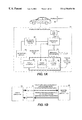
- FIG. 5 is a block diagram of the isolated and soft switched power converter 24 .
- the circuit configuration of the power converter 24 includes a primary resonant tank circuit 100 and a secondary resonant tank circuit 102 coupled back-to-back through an isolation transformer 104 .
- the primary resonant tank circuit 100 includes a pair of resonant capacitances 106 , 108 present in series as a resonant leg 110 , a pair of voltage sources, such as tank capacitors 112 , 114 , connected in series as a tank leg 116 , and a pair of voltage clamping and switching devices 118 , 120 coupled in series as resonant switches and voltage clamping devices for the resonant leg 110 .
- the primary resonant tank circuit 100 also includes a series inductor 124 in the center rail to smooth the voltage output during power flow from the secondary to the primary.
- the secondary resonant tank circuit 102 includes a pair of resonant capacitances 136 , 138 present in series as a resonant leg 140 , a pair of voltage sources, such as tank capacitors 142 , 144 , connected in series as a tank leg 146 , and a pair of equivalent switching devices 148 , 150 coupled in series as resonant switches and voltage clamping devices for the resonant leg 140 .
- the power converter 24 also includes a switching controller 160 for gating the switching elements 118 , 120 , 148 , and 150 .
- the switching controller 160 may be a circuit to generate a proper gating sequence to achieve soft-switching and output power (or voltage) control. The gating sequence is described below with reference to FIG. 7 and FIG. 13 .
- the individual functional blocks of FIG. 5 may be embodied in any type of suitable component that serves the described function.
- the voltage sources 112 , 114 , 142 , and 144 may be any type of device that maintains a relatively constant DC voltage, such as a tank capacitor, battery, a PV panel, or any other type of DC voltage source.
- the switching and voltage clamping elements 118 , 120 , 148 , and 150 may be transistors such as MOSFETs or IGBTs, thyristors, mechanical switches, or another type of switching device with an anti-parallel clamping diode or other type of voltage clamping device.
- Many suitable computing stations and circuits may serve as the switching controller 160 , including personal computers, workstations, minicomputers, application-specific digital/analog integrated circuits, and so forth.
- the resonant capacitances 106 , 108 , 136 , 138 are said to be “present” in the circuit to indicate that they may be a discrete component connected as shown, or they may be an inherent capacitance, such as the stray capacitance associated with switching and voltage clamping devices connected in a similar configuration. That is, the resonant capacitances 106 , 108 , 136 , 138 may be discrete capacitors, stray capacitances inherently present in the circuit, or any other suitable capacitance.
- the power converter 24 may include one or more additional inductors in series and/or parallel with the isolation transformer 104 to function as resonating inductors. As shown in FIG. 5, the windings of the isolation transformer 104 may serve as the resonant inductance, which may complicate the design of the transformer.
- FIG. 6 is a schematic diagram of an illustrative embodiment of the isolated and soft switched power converter 24 , which is suitable for the automotive and electric generation applications described elsewhere in this specification.
- the specific embodiment shown in FIG. 6 includes a primary resonant tank circuit 100 and a secondary resonant tank circuit 102 coupled back-to-back through an isolation transformer 104 .
- This transformer includes a primary input node 202 , a primary output node 204 , a secondary input node 206 , and a secondary output node 208 .
- the primary resonant tank circuit 100 includes a primary top rail 210 terminating in a primary top-rail terminal 211 , a primary center rail 212 terminating in a primary center-rail terminal 213 , and a primary bottom rail 214 terminating in a primary bottom-rail terminal 215 .
- a first primary resonant capacitance 216 (Cr 1 ) is present between the primary top rail 210 and the primary center rail 212 .
- a second primary resonant capacitance 218 (Cr 2 ) is present between the primary center rail 212 and the primary bottom rail 214 .
- a first primary resonant switch 220 (S 1 , in this case a MOSFET) is connected between the primary top rail 210 and the primary center rail 212 .
- a second primary resonant switch 222 (S 2 , in this case a MOSFET) is connected between the primary center rail 212 and the primary bottom rail 214 .
- a first primary clamping diode 224 (D 1 ) is connected between the primary top rail 210 and the primary center rail 212 .
- a second primary clamping diode 226 (D 2 ) is connected between the primary center rail 212 and the primary bottom rail 214 .
- a first primary tank capacitor 228 (C 1 ) is connected between the primary top rail 210 and a primary tap node 230 .
- a second primary tank capacitor 232 (C 2 ) is connected between the primary tap node 230 and the primary bottom rail 214 .
- the primary center rail 212 is connected to the primary input node 202 of the isolation transformer 104
- the primary tap node 230 is connected to the primary output node 204 of the isolation transformer.
- the primary resonant tank circuit also includes a series inductor 234 in the center rail 212 .
- the secondary resonant tank circuit 102 includes a secondary top rail 250 terminating in a secondary top-rail terminal 251 , a secondary center rail 252 terminating in a secondary center-rail terminal 253 , and a secondary bottom rail 254 terminating in a secondary bottom-rail terminal 255 .
- a first secondary resonant capacitance 256 (Cr 3 ) is present between the secondary top rail 250 and the secondary center rail 252 .
- a second secondary resonant capacitance 258 (Cr 4 ) is present between the secondary center rail 252 and the secondary bottom rail 254 .
- a first secondary resonant switch 260 (S 3 , in this case an IGBT) is connected between the secondary top rail 250 and the secondary center rail 252 .
- a second secondary resonant switch 262 (S 4 , in this case an IGBT) is connected between the secondary center rail 252 and the secondary bottom rail 254 .
- a first secondary clamping diode 264 (D 3 ) is connected between the secondary top rail 250 and the secondary center rail 252 .
- a second secondary clamping diode 266 (D 4 ) is connected between the secondary center rail 252 and the secondary bottom rail 254 .
- a first secondary tank capacitor 268 (C 3 ) is connected between the secondary top rail 250 and a secondary tap node 270 .
- a second secondary tank capacitor 272 (C 4 ) is connected between the secondary tap node 270 and the secondary bottom rail 254 .
- the secondary center rail 252 is connected to the secondary input node 206 of the isolation transformer 104
- the secondary tap node 270 is connected to the secondary output node 208 of the isolation transformer.
- the power converter 24 utilizes full DC voltage just like the traditional full bridge DC/DC converters, even though it is configured like a half bridge converter on each side of the transformer 104 .
- the power converter 24 includes two resonant tank circuits 100 (RT 1 ) and 102 (RT 2 ) coupled together through the isolation transformer 104 (Tr).
- Each resonant tank circuit consists of a pair of resonant capacitors (Cr 1 and Cr 2 /Cr 3 and Cr 4 ) connected in series as a resonant leg, a pair of tank capacitors (C 1 and C 2 /C 3 and C 4 ) connected in series as a tank leg, and a pair (or a device or configuration equivalent to a pair) of switching devices (S 1 -D 1 and S 2 -D 2 /S 3 -D 3 and S 4 -D 4 ) connected in series as resonant switches and clamping devices for the resonant leg.
- the two resonant tank circuits, RT 1 and RT 2 are disposed on the primary side and secondary side of the isolation transformer Tr, respectively.
- the resonant tank circuit RT 1 generates a quasi-resonant voltage Vr 1 across the primary of the transformer Tr.
- the switches S 1 and S 2 are zero-voltage turn-off and zero-current zero-voltage turn-on.
- FIG. 13 shows waveforms and control sequence of the resonant tank circuit RT 1 .
- the operating principle is very similar to “Auxiliary Resonant DC Tank Inverter” described in a commonly owned patent application filed on Oct. 28, 1997, U.S. patent application Ser. No. 08/959,200, which is incorporated herein by reference.
- the power rating of the power converter 24 is in the range of 1 to 100 kW, and the resonant frequency of the power converter is in the range of 10 to 100 kHz.
- the resonant frequency of the power converter is in the range of 10 to 100 kHz.
- electrical component values in the following ranges are typically appropriate, depending on specific design objectives and considerations:
- FIG. 7 is a timing diagram illustrating the gating sequence for the power converter 24 for one resonant cycle.
- This gating sequence repeats at the resonant frequency or switching frequency of the converter, typically in the range of 10 to 100 kHz for automotive and electric power applications. However, other resonant frequencies may be appropriate for other applications.
- the circuit will be described with S 1 and S 2 gated, with S 3 and S 4 held open, which produces power flow from the primary to the secondary. Specifically, S 1 is gated off at time t 1 , S 2 is gated on between times t 3 and t 4 , S 2 is gated off at time t 5 , and S 1 is gated on between times t 7 and t 8 . It will be appreciated that the same gating sequence may be used for S 3 and S 4 , with S 1 and S 2 held open, to transmit power from the secondary to the primary.
- FIG. 8 is an electric voltage diagram illustrating a voltage (Vr 1 ) waveform 800 on the primary side of the isolation transformer 104 of the power converter 24 in response to the gating sequence shown in FIG. 7 .
- the location of Vr 1 in the power converter circuit is shown on FIG. 6 .
- the voltage Vr 1 starts prior to time t 1 at a maximum steady-state value equal to the voltage V 1 across the first primary tank capacitor C 1 .
- the voltage Vr 1 drops until it reaches ⁇ V 2 , negative of the voltage across the second primary tank capacitor C 2 , at time t 3 .
- the voltage Vr 1 then remains at the steady state value ⁇ V 2 until time t 5 , when S 2 is gated off.
- S 2 is gated on while Vr 1 is at a steady-state value of ⁇ V 2 .
- the voltage Vr 1 rises until it reaches V 1 , the voltage across the first primary tank capacitor C 1 , at time t 7 .
- the voltage Vr 1 then remains at a steady state value of V 1 until the end of the cycle.
- S 1 is gated on while Vr 1 is at a steady-state value of V 1 .
- the voltage Vr 2 on the secondary side of the isolation transformer 104 has the same shape, except that it is boosted by the transformer turns ration “n” and may have a phase shift.
- FIG. 9 is an electric voltage diagram illustrating a voltage (Vcr 1 ) waveform 900 across the first primary resonant capacitor 216 (Cr 1 ) in response to the gating sequence shown in FIG. 7 .
- the location of Vcr 1 in the power converter circuit is shown on FIG. 6 .
- the voltage Vcr 1 starts prior to time t 1 at a zero steady-state value. Starting at time t 1 , when S 1 is gated off, the voltage Vcr 1 rises until it reaches V 1 +V 2 , the sum of the voltages across the first and second primary tank capacitors 228 (C 1 ) and 232 (C 2 ), at time t 3 .
- the voltage Vcr 1 then remains at the state value V 1 +V 2 until time t 5 , when S 2 is gated off. Thus, S 2 is gated on while Vcr 1 is at a steady-state value of V 1 +V 2 . Starting a time t 5 , when S 2 is gated off, the voltage Vcr 1 drops until it reaches zero at time t 7 . The voltage Vrc 1 then remains at a steady state value of zero until the end of the cycle. Thus, S 1 is gated on while Vcr 1 is at a steady-state value of zero.
- FIG. 10 is an electric voltage diagram illustrating a voltage (Vcr 2 ) waveform 1000 across the second primary resonant capacitor Cr 2 in response to the gating sequence shown in FIG. 7 .
- the location of Vcr 2 in the power converter circuit is shown on FIG. 6 .
- the voltage Vcr 1 is the inverse of Vcr 2 because Cr 1 and Cr 2 resonate and Vcr 1 +Vcr 2 equals the sum of the tank capacitor voltages V 1 +V 2 . That is, Vcr 2 starts prior to time t 1 at a steady-state rate value equal to V 1 +V 2 , the sum of the voltages across the first and second primary tank capacitors 228 (C 1 ) and 232 (C 2 ).
- FIG. 11 is an electric voltage diagram illustrating a voltage (Vcr 3 ) waveform 1100 across the first secondary resonant capacitor 256 (Cr 3 ) of the power converter 24 .
- the voltage Vcr 3 has a similar shape as the voltage Vcr 1 shown in FIG. 9, except that it is rises until it reaches V 3 +V 4 , the sum of the voltages across the first and second secondary tank capacitors 268 (C 3 ) and 272 (C 4 ), at time t 3 .
- FIG. 12 is an electric voltage diagram illustrating a voltage (Vcr 4 ) waveform 1200 on the second secondary resonant capacitor 258 (Cr 4 ) of the power converter 24 .
- This voltage is also referred to as the output voltage Vrb because a soft switched inverter can be connected across the secondary resonant capacitor 258 (Cr 4 ).
- the voltage Vcr 4 has a similar shape as the voltage Vcr 2 shown in FIG. 10, except that it is rises until it reaches V 3 +V 4 , the sum of the voltages across the first and second secondary tank capacitors 268 (C 3 ) and 272 (C 4 ), at time t 7 .
- the repeatedly obtained steady-state zero-voltage period from t 3 until t 5 allows an inverter connected across the center and bottom rails of the secondary tank circuit to soft switch.
- FIG. 13 is a combined timing, voltage and current diagram illustrating the operation of the power converter 24 .
- the gating sequence is also shown to illustrate how to generate the quasi-resonant output voltage Vr 1 on the primary side of the isolation transformer 104 (Tr).
- FIGS. 14-21 which show the current paths in the power converter 24 at various stages of the resonant cycle, will also be referred to during the following discussion of FIG. 13 .
- the arrows on FIGS. 14-21 indicate the direction of current flow, and the dashed lines around certain capacitors indicate that the capacitor is charged.
- the time from t 1 to t 9 it is one resonant cycle.
- the gating sequence shown in FIG. 13 is the same as that shown in FIG. 7 .
- switch S 1 Before t 1 , switch S 1 is on, and the resonant current Ir 1 through the transformer Tr increases (i.e., the energy stored in Tr increases) and Vr 1 is clamped to tank capacitor voltage V 1 .
- This state is shown in FIG. 14 .
- the switching device S 1 is gated off at t 1 .
- S 1 is zero-voltage turn-off because of capacitor Cr 1 's zero initial voltage.
- the resonant capacitors Cr 1 and Cr 2 and the transformer Tr's equivalent inductance (or stored energy) form a resonant circuit.
- the equivalent resonant current (Ir 1 -Id 1 ) starts to charge Cr 1 and discharge Cr 2 , that is, voltage Vr 1 starts to decrease from t 1 . This state is shown in FIG. 15 .
- the equivalent resonant current (Id 1 -Ir 1 ) charges Cr 2 and discharges Cr 1 .
- the output voltage Vr 1 increases.
- Vr 1 crosses the zero line at t 6
- the transformer current Ir 1 turns around from negative increasing and starts to increase positively.
- Vr 1 reaches the tank capacitor voltage V 1 , i.e., Cr 1 is discharged to zero and Cr 2 is charged to the total tank capacitor voltage (V 1 +V 2 ).
- the equivalent resonant current (Id 1 -Ir 1 ) attempts to overshoot Cr 2 's voltage, D 1 conducts and clamps Cr 2 's voltage; that is, Vr 1 is clamped to V 1 through D 1 .
- the diode D 1 conducts till Ir 1 becomes larger than Id 1 . This state is shown in FIG. 19 . At any time during D 1 's conduction period (t 7 -t 8 ), S 1 is gated on, thus accomplishing zero-current and zero-voltage turn-on.
- both S 1 and S 2 are zero-voltage turn-off and zero-current zero-voltage turn-on.
- the change rate (dV/dt) of the output voltage Vr 1 and resonant voltage Vcr 2 during the resonant periods (t 1 -t 3 ) and (t 5 -t 7 ) can be controlled by Cr 1 , Cr 2 , equivalent inductance of Tr, and preset turn-off current value Ioff.
- Vr 1 is controlled such that its average over one resonant cycle has to be zero. Therefore, the total voltage, (V 1 +V 2 ), is determined by the duty cycle of S 1 , which is defined below.
- the resonant tank circuit RT 2 is operated as a rectifier.
- Vr 2 n ⁇ Vr 1 ,
- V 3 n ⁇ V 1 ,
- V 4 n ⁇ V 2 ,
- Vrb n ⁇ Vcr 2 ,
- n is the turns ratio of the secondary winding over the primary winding of the transformer.
- FIG. 10 shows the waveform of the resonant voltage Vcr 2 and Vrb since Vcr 2 and Vrb have a similar shape with a factor of the turns ratio n.
- the zero-voltage period of Vrb provides an opportunity for the inverter to soft switch. Therefore, both resonant tank circuits are switched only when the inverter wants to switch for pulse-width modulation (PWM) in the case of DC/DC/AC power conversion.
- PWM pulse-width modulation
- Ts 1 and Ts 2 are switches S 1 's on time and S 2 's on time, respectively, as shown in FIGS. 7 and 13.
- the duty cycle can be set to any value between 0% to 100% according to applications.
- the duty cycle may be set to near 50%, resulting in V 1 approximately equal to V 2 , and V 3 approximately equal to V 4 .
- a higher duty cycle is desirable, so that V 2 is higher than V 1 , and V 2 is approximately equal to Vin (the voltage across the primary center-rail terminal 213 and the primary bottom-rail terminal 215 shown n FIG. 6 ).
- the resonant tank circuits are used to generate short zero-voltage periods for the inverter to switch.
- Vrb n ⁇ Vcr 2 .
- DC tank capacitor voltages (V 1 +V 2 ) and (V 3 +V 4 ), can be regulated by the duty cycle D to obtain a constant and stable voltage output regardless of ripples or variations from the input voltage Vin.
- FIG. 22 is a functional block diagram illustrating bidirectional power flow in the power converter 24 .
- the secondary resonant tank circuit 102 (RT 2 ) can be controlled as described above for the primary resonant tank circuit 100 (RT 1 ) with reference to FIG. 13 . That is, for power flow from the primary to the secondary, S 1 and S 2 are gated with S 3 and S 4 held open. The same gating sequence may be used for S 3 and S 4 , with S 1 and S 2 held open, to transmit power from the secondary to the primary. Referring to FIG.
- FIG. 23 is a circuit diagram illustrating an alternative power converter 2300 in which an inverter 2320 connected to the secondary tank circuit replaces the second secondary switching device 262 (S 4 ) and the second secondary clamping diode 266 (D 4 ) of the secondary tank circuit 102 (RT 2 ).
- the power converter 24 of FIG. 6 can be used as a DC/DC boost or buck converter, in which the input can be connected to the input terminals 213 and 215 and loads can be connected to the output terminals 251 and 255 (HV+and HV ⁇ ) to obtain regulated and isolated voltage.
- an inverter can be coupled to the terminals 253 and 255 (INV+ and INV ⁇ ), as shown in FIG. 23 .
- the second secondary switching device 262 (S 4 ) and the second secondary clamping diode 266 (D 4 ) can be eliminated by using the inverter as an equivalent switch and diode.
- the modified power converter is shown in FIG. 23, in which a three-phase inverter 2320 is illustrated as an example for DC/AC power conversion.
- This embodiment for DC/DC/AC power conversion has several advantages over traditional topologies. Only three switching devices are used for isolated DC/DC power conversion, resonant soft-switching, and bidirectional power flow implementation. All devices are soft-switched including the inverter for DC/AC power conversion, where S 1 , S 2 , and S 3 are zero-voltage turn-off and zero-current zero-voltage turn-on and the inverter switches are zero-voltage switching.
- low current and voltage stresses are implemented because the inverter switches carry only load current without additional superposed current for soft-switching and the DC/DC conversion switches carry the minimum current from the input voltage Vin to the load and sustain minimum voltage, thus achieving high efficiency.
- FIG. 24 is a circuit diagram illustrating an equivalent electrical circuit 2400 for the primary tank circuit 100 of the power converter 24 .
- Those skilled in the art will appreciate that it is possible to regulate the output voltage Vrb by controlling the duty cycle of only one resonant tank circuit, 100 or 102 .
- the high-voltage resonant tank circuit 102 of FIG. 6 may be used to control and regulate the output voltage Vrb, while the low-voltage resonant tank circuit 100 is operated at a 50% duty cycle.
- the low-voltage resonant tank circuit 100 generates a quasi-square-wave voltage acting as a voltage source across the primary of the transformer 104 .
- the high-voltage resonant tank circuit 102 can be operated in a manner to control its DC voltage, since it is completely equivalent to a conventional half-bridge PWM voltage-source converter connected to an AC source.
- FIG. 25 is a circuit diagram illustrating an alternative power converter 2500 including a shunt inductor 2520 connected across the primary side of the isolation transformer 104 (Lr).
- the resonant inductor, Lr is used as the resonating inductance for the resonant tank circuits 100 and 102 .
- FIG. 27 is a circuit diagram illustrating an alternative power converter 2700 in which stray capacitance provides the resonant capacitance. That is, the devices (S 1 /D 1 ), (S 2 /D 2 ), (S 3 /D 3 ), and (S 4 /D 4 )'s respective stray capacitance provide the resonating capacitances, Cr 1 , Cr 2 , Cr 3 , and Cr 4 , as shown in dashed lines. In this case, discrete external resonant capacitors can be omitted, although the voltage rise rate would be relatively high.
- FIG. 28 is a circuit diagram illustrating an alternative unidirectional power converter 2800 .
- switches S 3 and S 4 can be omitted and only diodes (D 3 and D 4 ) are used on the RT 2 side.
- FIGS. 23-29 illustrate methods for altering the power converter 24 , and other combinations and alternatives will be evident to those skilled in the art. For example, combining the teachings illustrated in FIGS. 27 and 28 yields another alternative embodiment 2900 shown in FIG. 29 .
- FIG. 30 is a block diagram of a bidirectional load-side electric storage and generation system 300 , which is suitable for providing energy storage and peak load shaving to the electric power grid 302 .
- the electric generation system 300 includes the soft-switched power converter 24 , a DC electric power generator, in this case a battery 304 , connected to the low-voltage (primary) side of the power converter.
- the system 300 also includes an inverter/rectifier 308 connected to the high-voltage (secondary) side of the power converter 24 .
- the inverter/rectifier 308 connects the battery 304 to the electric power grid 302 during peak-load periods. During off-peak periods, the inverter/rectifier 308 delivers power from the electric power grid 302 to recharge the battery 304 .
- the bidirectional power converter 24 shown in FIG. 6 is appropriate for this application.
- FIG. 31 is a block diagram of a unidirectional load-side electric storage and generation 310 system using a soft-switched power converter.
- the battery 304 is recharged by a local PV panel 314 .
- This obviates the need for power delivery from the electric power grid 302 to the battery 304 .
- the unidirectional power converter 2800 shown in FIG. 28 is appropriate for this application.
- the local PV panel 314 could be connected directly to the power converter 24 , with or without the battery 304 present in the circuit, as indicated by the dashed line.
- the power converter 2800 may be used to unidirectionally connect any type of DC power source to the electric power grid 302 as a load-side generator, and the power converter 24 may be used to bidirectionally connect any type of DC power source to the electric power grid 302 as a load-side generator.
- FIG. 32 is a schematic diagram illustrating the isolated and soft switched power converter 24 in a phase-based control mode.
- a phase delay across the isolation transformer 104 i.e., between the voltage waveforms of primary resonant tank circuit 100 and the voltage waveforms of secondary resonant tank circuit 100 ) is used to control the flow of the output power of the power converter 24 .
- the phase delay is created by gating all four (4) switches, S 1 , S 2 , S 3 , and S 4 within the same resonant cycle.
- FIGS. 14-21 illustrate the current flow for the “ideal” case in which the voltage waveform in the primary resonant tank circuit 100 is in phase with the voltage waveform in the secondary resonant tank circuit 102 .
- the current states for the secondary resonant tank circuit 102 illustrated in FIGS. 14-21 are delayed by the time associated with the phase shift.
- the heavier lines in FIGS. 34-42 illustrate the current states for this alternative.
- FIG. 33 is a combined timing, voltage and current diagram illustrating the phase-based mode for the power converter 24 .
- the time from t 1 to t 12 it is one resonant cycle.
- switch S 1 and S 3 are on, and the resonant current Ir 1 through the transformer Tr increases (i.e., the energy stored in Tr increases) and Vr 1 is clamped to tank capacitor voltage V 1 .
- This state is shown in FIG. 34 .
- the current through switch S 1 (Id 1 )
- loff the switching device S 1 is gated off at t 1 .
- S 1 is zero-voltage turn-off because of capacitor Cr 1 's zero initial voltage.
- the resonant capacitors Cr 1 and Cr 2 and the transformer Tr's equivalent inductance (or stored energy) form a resonant circuit.
- the equivalent resonant current (Ir 1 ) starts to charge Cr 1 and discharge Cr 2 , that is, voltage Vr 1 starts to decrease from t 1 . This state is shown in FIG. 35 .
- switch S 2 is gated on, thus accomplishing zero-current and zero-voltage turn-on.
- diode D 3 is conducting. This is shown in FIG. 36 .
- the current Ir 1 keeps decreasing.
- S 3 is gated off at t 5 .
- a resonant circuit then forms with the resonant capacitors Cr 3 and Cr 4 and the transformer Tr between t 5 and t 6 , similar to the period of t 1 to t 2 . This state is shown in FIG. 37 .
- the equivalent resonant current ⁇ Ir 1 charges Cr 3 and discharges Cr 4 , and the output voltage Vr 2 decreases.
- Vr 2 reaches the negative tank capacitor voltage V 4 , i.e., Cr 4 is discharged to zero and Cr 3 is charged to the total tank capacitor voltage (V 1 +V 2 ).
- D 4 conducts and clamps Cr 4 's voltage; that is, Vr 2 is clamped to ⁇ V 4 through D 4 .
- the diode D 4 conducts until ⁇ Ir 1 becomes larger than Id 1 .
- S 4 is gated on, thus accomplishing zero-current and zero-voltage turn-on. This state is shown in FIG. 38 .
- D 1 begins conducting.
- Ir 1 changes polarity again from negative to positive, which causes S 4 to start conducting and D 4 to stop conducting current.
- S 1 is gated on at any time during D 1 's conduction period (i.e., between t 8 and t 10 ), thereby achieving a zero-current and zero-voltage turn-on. This state is shown in FIG. 40 .
- S 4 is gated off, which causes Cr 3 to be discharged to zero, while Cr 4 is charged to V 3 +V 4 .
- D 3 starts conducting, which clamps Vr 2 to V 3 . This is shown in FIG. 41 .
- S 3 is gated on any time after t 12 , thereby again achieving a zero-current, zero-voltage switch.
- FIG. 42 is a circuit diagram illustrating the current and capacitor charge states in the power converter 24 after the twelfth time interval of the resonant cycle, which is the same as the first time interval. During this interval S 1 and D 3 are conducting.
- FIG. 43 is a timing diagram illustrating the phase shift between the voltage waveforms of the primary resonant tank circuit 100 and the secondary resonant tank circuit 102 for controlling the power converter 24 .
- the switching controller 160 gates all four resonant switches S 1 , S 2 , S 3 and S 4 in this control alternative to obtain the illustrated phase shift between the voltage waveforms for the primary and secondary resonant tank circuits.
- the control scheme illustrated by these figures results in a voltage waveform for the primary resonant tank circuit 100 that is very nearly in phase with the voltage waveform for the primary resonant tank circuit 102 (i.e., the voltage shown in FIG. 10 is very nearly in phase with the voltage shown in FIG. 12 ).
- the switching controller 160 shown in FIG. 3 controls both the primary and secondary resonant tank circuits 100 , 102 by gating the resonant switches of only one resonant tank circuit, with the switches of the other resonant tank circuit held open.
- the resonant switches S 1 and S 2 of the primary resonant tank circuit 100 are gated with the resonant switches S 3 and S 4 of the secondary resonant tank circuit 102 held open to cause power to flow from the primary side to the secondary side, whereas the resonant switches S 3 and S 4 of the secondary resonant tank circuit 102 are gated with the resonant switches S 1 and S 2 of the primary resonant tank circuit 100 held open to cause power to flow from the secondary side to the primary side.
- the power delivered by the converter can be indirectly controlled by varying the frequency of the resonant cycle.
- the impedance of the isolation transformer 104 varies as a function of the frequency of the resonant cycle (i.e., the impedance increases with increasing frequency), which allows the power flow through the transformer to be controlled by varying the frequency of the resonant cycle.
- the isolation transformer 104 can be operated as a variable current “choke” with a frequency-dependent impedance.
- controlling the resonant frequency indirectly controls the current flowing through the isolation transformer 104 .
- the voltage maintained by the tank capacitors C 1 , C 2 , C 3 and C 4 can be altered by varying the duty cycle of the resonant circuit. Basically, varying the duty cycle alters the charging time for the first and second tank capacitors of each resonant tank circuit, as described previously with reference to FIG. 10 . With a 50% duty cycle, for example, the voltage maintained by C 1 (V 1 ) will be approximately equal to the voltage maintained by C 2 (V 2 ), and the voltage maintained by C 3 (V 3 ) will be approximately equal to the voltage maintained by C 4 (V 4 ).
- varying the duty cycle results in an uneven distribution of the voltage between the first and second tank capacitors of each resonant tank circuit, and also alters the total voltage V 1 +V 2 and V 3 +V 4 , within the primary resonant tank circuit 100 and the secondary resonant tank circuit 102 , respectively.
- This allows manipulation of the duty cycle to control the quasi-DC output voltage (V 4 ) as well as the top rail to bottom rail DC output voltage, V 3 +V 4 .
- controlling the duty cycle indirectly controls the output voltage of the power converter 24 .
- the power flow through the power converter 24 can be controlled using indirect current control and indirect voltage control.
- the output current can be indirectly controlled by manipulating the frequency of the resonant cycle, which alters the impedance of the isolation transformer 104 .
- the power flow through the power converter 24 can be controlled by manipulating the duty cycle, which alters the output voltage (V 4 and V 3 +V 4 ).
- the isolation transformer 104 have a very small (i.e., negligible) series or “leakage” inductance.
- a significant leakage inductance in the isolation transformer 104 will temporarily store energy during the resonant cycle, and thus will cause a phase shift between the voltage waveforms in the primary and secondary resonant tank circuits 100 , 102 .
- the in-phase control scheme illustrated in FIGS. 7-22 will only occur if the isolation transformer 104 is effectively an “ideal” transformer with negligible leakage inductance, and thus exhibits no series impedance and no phase shift occurs across the transformer.
- the “ideal” isolation transformer 104 assumed in FIGS. 7-22 prevents the storage of energy in the transformer, and the resulting very nearly in-phase operation of the primary and secondary resonant circuits 100 , 102 .
- a very small or negligible phase shift between the voltage waveforms in the primary and secondary resonant circuits 100 , 102 results in a large power flow across the power converter 24 .
- power control for this configuration relies on the indirect current and voltage control methods described above because there is no direct control over the power flow. This may make precisely control and stability of the power flow across the power converter 24 difficult to achieve through manipulation of the gating sequence within the power converter 24 itself.
- the isolation transformer 104 will experience some level of leakage inductance, which will result in some amount of phase shift across the transformer. Moreover, constructing a transformer with nearly ideal characteristics can be prohibitively expensive. For this reason, it may be significant less expensive, and more realistic from a design standpoint, to construct a transformer with a non-negligible amount of leakage inductance.
- the indirect control scheme for the power converter 24 described above relies on varying the impedance of the isolation transformer 104 , which assumes the presence of series or leakage inductance.
- the isolation transformer 104 should be designed to participate in the resonant cycle by temporarily storing energy as power moves across the transformer during the resonant cycle, which results in a phase shift across the transformer as described.
- a series inductor may be added to the circuit between the resonant tank circuits 100 , 102 to operate as a resonant inductor.
- the phase shift across the isolation transformer 104 and the series resonant inductor, if present, can be directly controlled to control the power flow across the transformer.
- the power converter 24 to be operated as the power-controlling device through the phase-based control scheme illustrated is FIGS. 33-43.
- the phase-based control scheme illustrated illustrated is FIGS. 33-43 can be used when the power converter 24 is the power-driving device, and the simpler direct voltage control scheme illustrated in FIGS. 7-22 can be used when the converter follows a controlled power flow imposed by another device.
- the isolation transformer 104 has been replaced by its equivalent circuit, which includes the series inductors L 1 and L 2 representing the leakage inductance of the transformer.
- the shunt inductor M represents the mutual inductance of the transformer.
- the series inductors L 1 and L 2 represent a relatively small inductance that operates as a resonant inductor charging and discharging during each resonant cycle.
- the shunt inductor M represents a relatively large mutual inductance whose magnetizing current is substantially low. For this reason, the shunt inductor M may be ignored (i.e., considered an open circuit) for control purposes.
- phase-based control scheme illustrated in FIGS. 33-43 relies on independent control, or gating on and off, for all four resonant switches S 1 , S 2 , S 3 and S 4 . That is, the voltage waveform in each resonant tank circuit 100 , 102 is controlled independently to create a controlled phase shift between the waveforms, as shown best in FIGS. 33 and 43.
- the output power, P 0 may be controlled by regulating (1) the duty cycle, D; (2) the phase shift, ⁇ ; (3) the switching frequency, ⁇ ; or (4) any combination of the three variables.
- the power flow across the transformer 104 may be increased by increasing the phase shift, and may be decreased by decreasing the phase shift.
- the resulting phase-based control scheme for the power converter 24 allows precise control over the power flowing across the transformer 104 , while simultaneously providing for independent control over the duty cycles and resulting tank voltages for the primary and secondary resonant tank circuits 100 , 102 .
- This may be particularly desirable for a fuel-cell application, such as that shown in FIGS. 2A-2B, in which the secondary bus voltage varies significant within the fuel cell's operating range (e.g., 255 to 395 Volts DC) while the primary voltage remains relatively constant at a battery voltage (e.g., 12 or 36 Volts DC).
- phase-based control scheme for the power converter 24 allows precise control over the power flowing across the transformer 104 without having to vary the resonant frequency, which may simplify the design of other components, such as the power controller 26 , the isolation transformer 104 , and the CMEU controller 36 . This may be desirable because these devices may be easier to design and control for operation at a single frequency as opposed to a relatively wide range of operating frequencies.
- the switching controller 160 may implement a variety of techniques for controlling the power flow through the converter 24 , including the direct voltage control scheme illustrated in FIGS. 7-22 and the power control scheme illustrated in FIGS. 33-43. These control techniques may be further modified by indirect current control through manipulation of the resonant frequency, and direct voltage control through manipulation of the duty cycle. In the control scheme illustrated in FIGS. 33-43, precise and direct power-flow control is accomplished through controlled gating for all four resonant switches, resulting in manipulation of the phase shift across the isolation transformer 104 .
- the switching controller 160 may operate at a single resonant frequency to simplify design of the power controller 26 for soft-switching, may use phase control to control the power flow through the converter 24 , and may use duty cycle manipulation to control the bus voltage for the fuel cell 54 .
- the converter 24 may also operate as a variable-frequency device to facilitate frequency-based speed control by the control power controller 26 . This may be desirable to assist in other requirements, such as start-up of the power converter 24 and so forth.
- Those skilled in the art will appreciate that many other control objectives may be accomplished through combinations and modifications of the versatile control techniques described above for the power converter 24 and the alternative configurations illustrated in FIGS. 23-29.
Abstract
Description


Claims (31)
Priority Applications (1)
| Application Number | Priority Date | Filing Date | Title |
|---|---|---|---|
| US09/399,397 US6370050B1 (en) | 1999-09-20 | 1999-09-20 | Isolated and soft-switched power converter |
Applications Claiming Priority (1)
| Application Number | Priority Date | Filing Date | Title |
|---|---|---|---|
| US09/399,397 US6370050B1 (en) | 1999-09-20 | 1999-09-20 | Isolated and soft-switched power converter |
Publications (1)
| Publication Number | Publication Date |
|---|---|
| US6370050B1 true US6370050B1 (en) | 2002-04-09 |
Family
ID=23579350
Family Applications (1)
| Application Number | Title | Priority Date | Filing Date |
|---|---|---|---|
| US09/399,397 Expired - Fee Related US6370050B1 (en) | 1999-09-20 | 1999-09-20 | Isolated and soft-switched power converter |
Country Status (1)
| Country | Link |
|---|---|
| US (1) | US6370050B1 (en) |
Cited By (96)
| Publication number | Priority date | Publication date | Assignee | Title |
|---|---|---|---|---|
| US6522103B1 (en) * | 2000-08-22 | 2003-02-18 | Hitachi, Ltd. | Sodium-sulphur battery system and driving method thereof |
| US6556460B2 (en) * | 2001-08-29 | 2003-04-29 | Hitachi, Ltd. | Method for controlling a vehicle provided with an electric power converter |
| US6628006B2 (en) * | 2001-05-03 | 2003-09-30 | Ford Motor Company | System and method for recovering potential energy of a hydrogen gas fuel supply for use in a vehicle |
| US20030218887A1 (en) * | 2002-04-30 | 2003-11-27 | Kojori Hassan A. | Synchronous and bi-directional variable frequency power conversion systems |
| US6657274B2 (en) | 2001-10-11 | 2003-12-02 | Microsemi Corporation | Apparatus for controlling a high voltage circuit using a low voltage circuit |
| US6798162B2 (en) | 2002-07-17 | 2004-09-28 | Siemens Vdo Automotive Inc. | 12/42 volt DC brush motor control system |
| US20050006958A1 (en) * | 2003-07-11 | 2005-01-13 | Dubovsky Stephen M. | Grid-connected power systems having back-up power sources and methods of providing back-up power in grid-connected power systems |
| US20050116668A1 (en) * | 2002-04-19 | 2005-06-02 | Jeppe Bastholm | Drive unit, preferably an actuator, a control and a construction |
| US20050156541A1 (en) * | 2004-01-20 | 2005-07-21 | Nicollet Technologies Corporation | Multiple discharge load electronic ballast system |
| US6930897B2 (en) * | 2001-07-31 | 2005-08-16 | Abb Research Ltd. | Fuel cell inverter |
| US20050179264A1 (en) * | 2004-02-18 | 2005-08-18 | Evgeni Ganev | Hybrid-electric vehicle having a matched reactance machine |
| US20060152085A1 (en) * | 2004-10-20 | 2006-07-13 | Fred Flett | Power system method and apparatus |
| US20060152199A1 (en) * | 2002-11-13 | 2006-07-13 | Lennart Angquist | Auxiliary power supply |
| US20060187686A1 (en) * | 2005-02-21 | 2006-08-24 | Chaoqun Sun | LLC series resonant converter and the driving method for the synchronous rectification power switches thereof |
| US20060250902A1 (en) * | 2005-05-05 | 2006-11-09 | Afs Trinity Power Corporation | Plug-in hybrid vehicle with fast energy storage |
| US20060267542A1 (en) * | 2005-05-27 | 2006-11-30 | Lixiang Wei | Pulse width modulation (PWM) rectifier with variable switching frequency |
| US20070007939A1 (en) * | 2005-05-16 | 2007-01-11 | Miller John M | Low voltage electrical vehicle propulsion system using double layer capacitors |
| US20070068714A1 (en) * | 2005-09-23 | 2007-03-29 | Afs Trinity Power Corporation | Method and apparatus for power electronics and control of plug-in hybrid propulsion with fast energy storage |
| US20070195557A1 (en) * | 2006-02-21 | 2007-08-23 | Ut-Battelle Llc | Triple voltage DC-to-DC converter and method |
| US20070247880A1 (en) * | 2006-04-19 | 2007-10-25 | Postech Foundation | Full-bridge active clamp dc-dc converter |
| US7308614B2 (en) | 2002-04-30 | 2007-12-11 | Honeywell International Inc. | Control sequencing and prognostics health monitoring for digital power conversion and load management |
| EP1870996A1 (en) * | 2006-06-24 | 2007-12-26 | SMA Technologie AG | Circuit for feeding electric energy in a electric utility grid |
| US20080013351A1 (en) * | 2006-06-06 | 2008-01-17 | Ideal Power Converters, Inc. | Universal Power Converter |
| US20080048602A1 (en) * | 2005-03-02 | 2008-02-28 | Conrad Rossel | Vehicle drive |
| US20080079312A1 (en) * | 2006-09-29 | 2008-04-03 | Ford Global Technologies, Llc | Energy conversion system for a vehicle |
| US20080094019A1 (en) * | 2004-11-15 | 2008-04-24 | General Electric Company | Bidirectional buck-boost power converters |
| US20080136374A1 (en) * | 2006-12-08 | 2008-06-12 | Nelson Jody J | Power device for a vehicle |
| US20080205109A1 (en) * | 2007-02-26 | 2008-08-28 | Lear Corporation | Energy distribution system for vehicle |
| US20080212340A1 (en) * | 2005-06-09 | 2008-09-04 | Koninklijke Philips Electronics, N.V. | Method For Operating A Power Converter In A Soft-Switching Range |
| US20090034299A1 (en) * | 2007-07-31 | 2009-02-05 | Dubitsky Lev | Apparatus and method for high efficiency isolated power converter |
| US20090059622A1 (en) * | 2007-08-28 | 2009-03-05 | Hitachi Computer Peripherals Co., Ltd. | Bi-directional dc-dc converter and method for controlling the same |
| US20090243558A1 (en) * | 2008-03-31 | 2009-10-01 | Nicollet Technologies Corporation | Electronic ballast with hold-up energy storage |
| US20090251060A1 (en) * | 2008-03-31 | 2009-10-08 | Nicollet Technologies Corporation | Electronic ballast system with lamp interface network |
| US20100141031A1 (en) * | 2007-03-07 | 2010-06-10 | Denso Corporation | Load driving method and device |
| WO2011011475A1 (en) * | 2009-07-21 | 2011-01-27 | Danfoss Turbocor Compressors Bv | A zero-voltage-transition soft switching converter |
| WO2011022442A2 (en) * | 2009-08-17 | 2011-02-24 | Ideal Power Converters Inc. | Power conversion with added pseudo-phase |
| US20110175460A1 (en) * | 2008-06-10 | 2011-07-21 | Abb Technology Ag | Dc current breaker |
| US20110194206A1 (en) * | 2010-02-10 | 2011-08-11 | Hitachi, Ltd. | Power-Supply Unit, Hard-Disk Drive, and Switching Method of the Power-Supply Unit |
| WO2011100827A1 (en) * | 2010-02-18 | 2011-08-25 | Peter Waldemar Lehn | Dc-dc converter circuit for high input-to-output voltage conversion |
| US20110216567A1 (en) * | 2010-03-02 | 2011-09-08 | Suntec Enterprises | Single switch inverter |
| FR2957701A1 (en) * | 2010-03-19 | 2011-09-23 | Peugeot Citroen Automobiles Sa | Method for estimating reliability of electronic logic controller of hybrid vehicle, involves determining failure rates under effects of voltages of components, and determining average variation of failure rates between voltages |
| US20110317452A1 (en) * | 2010-06-25 | 2011-12-29 | Gueorgui Iordanov Anguelov | Bi-directional power converter with regulated output and soft switching |
| US20120013456A1 (en) * | 2010-07-19 | 2012-01-19 | Pock Leslie A | System and method for signaling, marketing, and advertising alternative fuel-based vehicles |
| US20120032633A1 (en) * | 2009-04-09 | 2012-02-09 | Ralf Cordes | Transmission of power bidirectionally and without contact to charge electric vehicles |
| CN102386453A (en) * | 2010-08-26 | 2012-03-21 | 福特全球技术公司 | Method for charging an auxilary battery in a plug-in electric vehicle |
| WO2012055862A2 (en) | 2010-10-28 | 2012-05-03 | Eltek Valere As | Method for controlling a series resonant dc/dc converter |
| WO2012055869A3 (en) * | 2010-10-28 | 2012-06-28 | Eltek Valere As | Series resonant dc/dc converter |
| US8391033B2 (en) | 2009-06-29 | 2013-03-05 | Ideal Power Converters, Inc. | Power transfer devices, methods, and systems with crowbar switch shunting energy-transfer reactance |
| US8432709B2 (en) | 2010-10-08 | 2013-04-30 | Industrial Technology Research Institute | DC-to-AC power inverting apparatus for photovoltaic modules |
| US8446042B2 (en) | 2010-11-30 | 2013-05-21 | Ideal Power Converters, Inc. | Photovoltaic array systems, methods, and devices with improved diagnostics and monitoring |
| US8514601B2 (en) | 2009-08-17 | 2013-08-20 | Ideal Power Converters, Inc. | Power conversion with added pseudo-phase |
| US8531858B2 (en) | 2011-02-18 | 2013-09-10 | Ideal Power, Inc. | Power conversion with current sensing coupled through saturating element |
| JP2014054176A (en) * | 2012-09-06 | 2014-03-20 | Lg Innotek Co Ltd | Power-feeding device |
| US20140104907A1 (en) * | 2012-10-12 | 2014-04-17 | Hitachi Information & Telecommunication Engineering, Ltd. | Power Supply Unit and Operating Method of the Same |
| ITTO20121112A1 (en) * | 2012-12-20 | 2014-06-21 | Ansaldobreda Spa | PILOT METHOD FOR INVERTERS AND INVERTERS TO REDUCE SWITCHING LOSSES |
| US20140254204A1 (en) * | 2013-03-07 | 2014-09-11 | Chung Shan Institute Of Science And Technology, Armaments Bureau, M.N.D | Half-bridge dc/dc converter with asymmetric pulse controlling process |
| US20140334189A1 (en) * | 2013-05-07 | 2014-11-13 | Delta Electronics, Inc. | Bi-directional dc-dc converter |
| KR20140135237A (en) * | 2012-03-14 | 2014-11-25 | 레이니쉬-웨스트펠리쉐 테크니쉐 호크슐레 아아켄 | Current control for DC-DC converters |
| US9059636B2 (en) | 2010-02-18 | 2015-06-16 | Peter Waldemar Lehn | DC-DC converter circuit using LLC circuit in the region of voltage gain above unity |
| US9088224B2 (en) | 2010-07-21 | 2015-07-21 | Lihua Chen | Variable voltage converter with stabilized output voltage |
| US9118213B2 (en) | 2010-11-24 | 2015-08-25 | Kohler Co. | Portal for harvesting energy from distributed electrical power sources |
| US20150295502A1 (en) * | 2014-04-09 | 2015-10-15 | Toyota Jidosha Kabushiki Kaisha | Power conversion device and power conversion method |
| US20160200202A1 (en) * | 2015-01-13 | 2016-07-14 | General Electric Company | Bi-directional dc-dc power converter for a vehicle system |
| US9397580B1 (en) * | 2006-06-06 | 2016-07-19 | Ideal Power, Inc. | Dual link power converter |
| US9413271B2 (en) | 2013-03-14 | 2016-08-09 | Combined Energies, Llc | Power conversion system with a DC to DC boost converter |
| US20160315557A1 (en) * | 2015-04-23 | 2016-10-27 | Panasonic Intellectual Property Management Co., Ltd. | Power converter |
| US20160329077A1 (en) * | 2015-05-05 | 2016-11-10 | Seagate Technology Llc | Motor spin up with auxiliary power boost |
| EP2348626A3 (en) * | 2005-07-29 | 2017-04-19 | TDK Corporation | Switching power supply with surge voltage suppression |
| US9634485B2 (en) | 2013-04-01 | 2017-04-25 | Protonex Technology Corporation | Power manager |
| DE102015226673A1 (en) | 2015-12-23 | 2017-06-29 | Audi Ag | High-voltage DC-DC converter for charging an electric vehicle and operating method for the converter |
| EP3190691A1 (en) * | 2015-12-28 | 2017-07-12 | Harman International Industries, Inc. | Gated bi-directional dual-rail series resonant converter power supply |
| CN107104497A (en) * | 2017-04-25 | 2017-08-29 | 榆林学院 | A kind of solar electric power supply system |
| US20180109172A1 (en) * | 2016-10-19 | 2018-04-19 | Fu-Tzu HSU | Damper and an electrical energy converting device using the same |
| US20180159435A1 (en) * | 2016-12-07 | 2018-06-07 | Carl David Klaes | Modified dual active half bridge dc/dc converter with transformer dc bias |
| US20180198373A1 (en) * | 2016-07-07 | 2018-07-12 | Huawei Technologies Co., Ltd. | Four-switch three phase dc-dc resonant converter |
| GB2566479A (en) * | 2017-09-14 | 2019-03-20 | Eltek As | DC-DC Converter |
| US10243192B2 (en) | 2015-09-09 | 2019-03-26 | Bren-Tronics, Inc. | Modular battery case for prismatic cells and portable off-grid power storage and delivery system |
| US10256511B2 (en) | 2015-05-28 | 2019-04-09 | Bren-Tronics, Inc. | Secondary battery housing with control electronics |
| US10261113B2 (en) * | 2014-06-30 | 2019-04-16 | Chengdu Monolithic Power Systems Co., Ltd. | Power converter with average current detection and the detecting circuit and method thereof |
| US10320018B2 (en) | 2013-03-14 | 2019-06-11 | Combined Energies, Llc | Dynamically responsive high efficiency CCHP system |
| US10326284B2 (en) | 2014-11-11 | 2019-06-18 | Revision Military Ltd. | Control module for DC power network |
| US10333315B2 (en) | 2009-07-10 | 2019-06-25 | Revision Military Ltd. | Power managers and methods for operating power managers |
| US20190267827A1 (en) * | 2016-11-15 | 2019-08-29 | Huawei Technologies Co., Ltd. | Charging and discharging apparatus |
| CN110190752A (en) * | 2019-05-17 | 2019-08-30 | 中南大学 | A kind of two-way CLLLC-DCX controlled resonant converter and its control method |
| CN110545045A (en) * | 2019-09-20 | 2019-12-06 | 成都信息工程大学 | isolated three-half-bridge AC/DC converter circuit and control method thereof |
| CN110729902A (en) * | 2019-09-09 | 2020-01-24 | 西安奇点能源技术有限公司 | Novel bidirectional DC-DC converter |
| US10587116B2 (en) | 2015-11-20 | 2020-03-10 | Galvion Soldier Power, Llc | Distributed power manager |
| US10848067B2 (en) | 2015-11-20 | 2020-11-24 | Galvion Soldier Power, Llc | Power manager with reconfigurable power converting circuits |
| CN112383057A (en) * | 2020-11-27 | 2021-02-19 | 哈尔滨工程大学 | Power grid flow-based mutual inductance and self-inductance design method for power coupling system |
| US11063523B2 (en) | 2019-01-16 | 2021-07-13 | Delta Electronics (Shanghai) Co., Ltd | DC/DC converter and control method thereof |
| US11190104B2 (en) * | 2019-01-16 | 2021-11-30 | Delta Electronics (Shanghai) Co., Ltd | DC/DC converter and method for controlling phase shift angle thereof |
| US11258366B2 (en) | 2015-11-20 | 2022-02-22 | Galvion Soldier Power, Llc | Power manager with reconfigurable power converting circuits |
| US20220060119A1 (en) * | 2020-08-18 | 2022-02-24 | Lear Corporation | Dc-to-dc converter |
| CN114374328A (en) * | 2022-01-17 | 2022-04-19 | 中车青岛四方车辆研究所有限公司 | DC-DC converter of double-current system auxiliary converter system and control method thereof |
| US20220173668A1 (en) * | 2020-11-27 | 2022-06-02 | Lear Corporation | Wide hv-input range dc-dc converter |
| US11784600B2 (en) | 2017-01-25 | 2023-10-10 | General Electric Company | Systems and methods for a soft switching DC-DC converter |
Citations (7)
| Publication number | Priority date | Publication date | Assignee | Title |
|---|---|---|---|---|
| US4523269A (en) * | 1983-11-16 | 1985-06-11 | Reliance Electric Company | Series resonance charge transfer regulation method and apparatus |
| US4953068A (en) * | 1989-11-08 | 1990-08-28 | Unisys Corporation | Full bridge power converter with multiple zero voltage resonant transition switching |
| US5027264A (en) * | 1989-09-29 | 1991-06-25 | Wisconsin Alumni Research Foundation | Power conversion apparatus for DC/DC conversion using dual active bridges |
| US5172309A (en) | 1991-08-07 | 1992-12-15 | General Electric Company | Auxiliary quasi-resonant dc link converter |
| US5255174A (en) | 1991-10-18 | 1993-10-19 | Allied-Signal Inc. | Regulated bi-directional DC-to-DC voltage converter which maintains a continuous input current during step-up conversion |
| US5559685A (en) | 1994-10-12 | 1996-09-24 | Electronic Power Conditioning, Inc. | Voltage clamped parallel resonant converter with controllable duty cycle |
| WO1999022438A1 (en) | 1997-10-28 | 1999-05-06 | Lockheed Martin Energy Research Corporation | Auxiliary resonant dc tank converter |
-
1999
- 1999-09-20 US US09/399,397 patent/US6370050B1/en not_active Expired - Fee Related
Patent Citations (7)
| Publication number | Priority date | Publication date | Assignee | Title |
|---|---|---|---|---|
| US4523269A (en) * | 1983-11-16 | 1985-06-11 | Reliance Electric Company | Series resonance charge transfer regulation method and apparatus |
| US5027264A (en) * | 1989-09-29 | 1991-06-25 | Wisconsin Alumni Research Foundation | Power conversion apparatus for DC/DC conversion using dual active bridges |
| US4953068A (en) * | 1989-11-08 | 1990-08-28 | Unisys Corporation | Full bridge power converter with multiple zero voltage resonant transition switching |
| US5172309A (en) | 1991-08-07 | 1992-12-15 | General Electric Company | Auxiliary quasi-resonant dc link converter |
| US5255174A (en) | 1991-10-18 | 1993-10-19 | Allied-Signal Inc. | Regulated bi-directional DC-to-DC voltage converter which maintains a continuous input current during step-up conversion |
| US5559685A (en) | 1994-10-12 | 1996-09-24 | Electronic Power Conditioning, Inc. | Voltage clamped parallel resonant converter with controllable duty cycle |
| WO1999022438A1 (en) | 1997-10-28 | 1999-05-06 | Lockheed Martin Energy Research Corporation | Auxiliary resonant dc tank converter |
Non-Patent Citations (6)
| Title |
|---|
| "A Novel Control Principle of Bi-Directional DC-DC Power Conversion," by Reimann et al., IEEE Proceedings, 1997, IEEE Document 0-7803-3840-5/97, pp. 978-984. |
| "A PWM Method for Quasi-Resonant Zero-Voltage-Switching Inverter," by Taniguchi et al., The European Power Electronics Association, 1993, pp. 41-45. |
| "A Three-Phase Soft-Switched High-Power-Density dc/dc Converter for High-Power Applications," by DeDoncker et al., IEEE Transactions on Industry Applications, vol. 27, No. 1, Jan./Feb. 1991, pp. 63-73. |
| "Bi-Directional DC to DC Converters for Fuel Cell Systems," by Wang et al., IEEE Proceedings, 1998, IEEE Document 0-7803-4398-0/98, pp. 47-51. |
| "Design Considerations for High Power Density DC/DC Converters," by Kheraluwala et al., HFPC, May 1990 Proceedings, pp. 324-335. |
| "The Auxiliary Quasi-Resonant DC Link Inverter," by DeDoncker et al., PESC '91 Record, 22nd Annual IEEE Power Electronics Specialists Conference, Jun. 1991, Boston, Mass., pp. 248-253. |
Cited By (192)
| Publication number | Priority date | Publication date | Assignee | Title |
|---|---|---|---|---|
| US6522103B1 (en) * | 2000-08-22 | 2003-02-18 | Hitachi, Ltd. | Sodium-sulphur battery system and driving method thereof |
| US20040046395A1 (en) * | 2001-05-03 | 2004-03-11 | Oglesby Keith Andrew | System and method for recovering potential energy of a hydrogen gas fuel supply for use in a vehicle |
| US6628006B2 (en) * | 2001-05-03 | 2003-09-30 | Ford Motor Company | System and method for recovering potential energy of a hydrogen gas fuel supply for use in a vehicle |
| US6930897B2 (en) * | 2001-07-31 | 2005-08-16 | Abb Research Ltd. | Fuel cell inverter |
| US6633495B2 (en) * | 2001-08-29 | 2003-10-14 | Hitachi, Ltd. | DC apparatus and vehicle using the same |
| US6556460B2 (en) * | 2001-08-29 | 2003-04-29 | Hitachi, Ltd. | Method for controlling a vehicle provided with an electric power converter |
| US6657274B2 (en) | 2001-10-11 | 2003-12-02 | Microsemi Corporation | Apparatus for controlling a high voltage circuit using a low voltage circuit |
| US6853047B1 (en) | 2001-10-11 | 2005-02-08 | Microsemi Corporation | Power supply with control circuit for controlling a high voltage circuit using a low voltage circuit |
| US20050116668A1 (en) * | 2002-04-19 | 2005-06-02 | Jeppe Bastholm | Drive unit, preferably an actuator, a control and a construction |
| US7847494B2 (en) * | 2002-04-19 | 2010-12-07 | Linak A/S | Drive unit, preferably an actuator, a control and a construction |
| US20030218887A1 (en) * | 2002-04-30 | 2003-11-27 | Kojori Hassan A. | Synchronous and bi-directional variable frequency power conversion systems |
| US7308614B2 (en) | 2002-04-30 | 2007-12-11 | Honeywell International Inc. | Control sequencing and prognostics health monitoring for digital power conversion and load management |
| US6850426B2 (en) | 2002-04-30 | 2005-02-01 | Honeywell International Inc. | Synchronous and bi-directional variable frequency power conversion systems |
| US6798162B2 (en) | 2002-07-17 | 2004-09-28 | Siemens Vdo Automotive Inc. | 12/42 volt DC brush motor control system |
| US20060152199A1 (en) * | 2002-11-13 | 2006-07-13 | Lennart Angquist | Auxiliary power supply |
| US7317301B2 (en) * | 2002-11-13 | 2008-01-08 | Abb Ab | Auxiliary power supply |
| US20050006958A1 (en) * | 2003-07-11 | 2005-01-13 | Dubovsky Stephen M. | Grid-connected power systems having back-up power sources and methods of providing back-up power in grid-connected power systems |
| US6949843B2 (en) | 2003-07-11 | 2005-09-27 | Morningstar, Inc. | Grid-connected power systems having back-up power sources and methods of providing back-up power in grid-connected power systems |
| US7009347B2 (en) * | 2004-01-20 | 2006-03-07 | Nicollet Technologies Corporation | Multiple discharge load electronic ballast system |
| US20050156541A1 (en) * | 2004-01-20 | 2005-07-21 | Nicollet Technologies Corporation | Multiple discharge load electronic ballast system |
| US20050179264A1 (en) * | 2004-02-18 | 2005-08-18 | Evgeni Ganev | Hybrid-electric vehicle having a matched reactance machine |
| US7148649B2 (en) | 2004-02-18 | 2006-12-12 | Honeywell International, Inc. | Hybrid-electric vehicle having a matched reactance machine |
| US20060152085A1 (en) * | 2004-10-20 | 2006-07-13 | Fred Flett | Power system method and apparatus |
| US8138694B2 (en) * | 2004-11-15 | 2012-03-20 | General Electric Company | Bidirectional buck-boost power converters |
| US20080094019A1 (en) * | 2004-11-15 | 2008-04-24 | General Electric Company | Bidirectional buck-boost power converters |
| US7184280B2 (en) * | 2005-02-21 | 2007-02-27 | Delta Electronics, Inc. | LLC series resonant converter and the driving method for the synchronous rectification power switches thereof |
| US20060187686A1 (en) * | 2005-02-21 | 2006-08-24 | Chaoqun Sun | LLC series resonant converter and the driving method for the synchronous rectification power switches thereof |
| US20080048602A1 (en) * | 2005-03-02 | 2008-02-28 | Conrad Rossel | Vehicle drive |
| US20060250902A1 (en) * | 2005-05-05 | 2006-11-09 | Afs Trinity Power Corporation | Plug-in hybrid vehicle with fast energy storage |
| EP1883552A4 (en) * | 2005-05-05 | 2011-04-27 | Afs Trinity Power Corp | Plug-in hybrid vehicle with fast energy storage |
| EP1883552A2 (en) * | 2005-05-05 | 2008-02-06 | AFS Trinity Power Corporation | Plug-in hybrid vehicle with fast energy storage |
| US20070007939A1 (en) * | 2005-05-16 | 2007-01-11 | Miller John M | Low voltage electrical vehicle propulsion system using double layer capacitors |
| US7190143B2 (en) * | 2005-05-27 | 2007-03-13 | Rockwell Automation Technologies, Inc. | Pulse width modulation (PWM) rectifier with variable switching frequency |
| US20060267542A1 (en) * | 2005-05-27 | 2006-11-30 | Lixiang Wei | Pulse width modulation (PWM) rectifier with variable switching frequency |
| US20080212340A1 (en) * | 2005-06-09 | 2008-09-04 | Koninklijke Philips Electronics, N.V. | Method For Operating A Power Converter In A Soft-Switching Range |
| EP2348626A3 (en) * | 2005-07-29 | 2017-04-19 | TDK Corporation | Switching power supply with surge voltage suppression |
| EP1935101A2 (en) * | 2005-09-23 | 2008-06-25 | AFS Trinity Power Corporation | Method and apparatus for power electronics and control of plug-in hybrid propulsion with fast energy storage |
| US7740092B2 (en) | 2005-09-23 | 2010-06-22 | Afs Trinity Power Corporation | Method and apparatus for power electronics and control of plug-in hybrid propulsion with fast energy storage |
| CN101309810B (en) * | 2005-09-23 | 2012-07-04 | Afs三一电力公司 | Method and apparatus for power electronics and control of plug-in hybrid propulsion with fast energy storage |
| US20070068714A1 (en) * | 2005-09-23 | 2007-03-29 | Afs Trinity Power Corporation | Method and apparatus for power electronics and control of plug-in hybrid propulsion with fast energy storage |
| WO2007037972A3 (en) * | 2005-09-23 | 2007-05-24 | Afs Trinity Power Corp | Method and apparatus for power electronics and control of plug-in hybrid propulsion with fast energy storage |
| AU2006295147B2 (en) * | 2005-09-23 | 2011-04-28 | Afs Trinity Power Corporation | Method and apparatus for power electronics and control of plug-in hybrid propulsion with fast energy storage |
| EP1935101A4 (en) * | 2005-09-23 | 2011-04-27 | Afs Trinity Power Corp | Method and apparatus for power electronics and control of plug-in hybrid propulsion with fast energy storage |
| US7408794B2 (en) * | 2006-02-21 | 2008-08-05 | Ut-Battele Llc | Triple voltage dc-to-dc converter and method |
| US20070195557A1 (en) * | 2006-02-21 | 2007-08-23 | Ut-Battelle Llc | Triple voltage DC-to-DC converter and method |
| US20070247880A1 (en) * | 2006-04-19 | 2007-10-25 | Postech Foundation | Full-bridge active clamp dc-dc converter |
| KR100772659B1 (en) | 2006-04-19 | 2007-11-01 | 학교법인 포항공과대학교 | Full-bridge active clamp dc-dc converter |
| US9130461B2 (en) * | 2006-06-06 | 2015-09-08 | Ideal Power Inc. | Universal power conversion methods with disconnect after driving |
| US9899932B2 (en) * | 2006-06-06 | 2018-02-20 | Ideal Power, Inc. | Universal power conversion apparatus |
| US7599196B2 (en) | 2006-06-06 | 2009-10-06 | Ideal Power Converters, Inc. | Universal power converter |
| US20080031019A1 (en) * | 2006-06-06 | 2008-02-07 | Ideal Power Converters, Inc., | Universal Power Conversion Methods |
| US20160072400A1 (en) * | 2006-06-06 | 2016-03-10 | Ideal Power Inc. | Universal Power Conversion Methods |
| US8345452B2 (en) | 2006-06-06 | 2013-01-01 | Ideal Power Converters, Inc. | Universal power converter with bidirectional switching devices |
| US7778045B2 (en) | 2006-06-06 | 2010-08-17 | Ideal Power Converters, Inc. | Universal power conversion methods |
| US8395910B2 (en) | 2006-06-06 | 2013-03-12 | Ideal Power Converters, Inc. | Buck-boost power converter circuits, methods and systems |
| US9397580B1 (en) * | 2006-06-06 | 2016-07-19 | Ideal Power, Inc. | Dual link power converter |
| US8400800B2 (en) | 2006-06-06 | 2013-03-19 | Ideal Power Converters, Inc. | Universal power converter with two input drive operations during each half-cycle |
| US20080013351A1 (en) * | 2006-06-06 | 2008-01-17 | Ideal Power Converters, Inc. | Universal Power Converter |
| US20140133203A1 (en) * | 2006-06-06 | 2014-05-15 | Ideal Power Converters, Inc. | Universal Power Conversion Methods |
| CN101523710B (en) * | 2006-06-06 | 2014-03-05 | 威廉·亚历山大 | Universal power converter |
| WO2008008143A3 (en) * | 2006-06-06 | 2008-09-04 | William Alexander | Universal power converter |
| EP1870996A1 (en) * | 2006-06-24 | 2007-12-26 | SMA Technologie AG | Circuit for feeding electric energy in a electric utility grid |
| US8232669B2 (en) * | 2006-09-29 | 2012-07-31 | Ford Global Technologies, Llc | Energy conversion system for a vehicle |
| US9597977B2 (en) | 2006-09-29 | 2017-03-21 | Ford Global Technologies, Llc | Energy conversion system for a vehicle |
| US9018796B2 (en) | 2006-09-29 | 2015-04-28 | Ford Global Technologies, Llc | Energy conversion system for a vehicle |
| US20080079312A1 (en) * | 2006-09-29 | 2008-04-03 | Ford Global Technologies, Llc | Energy conversion system for a vehicle |
| US20080136374A1 (en) * | 2006-12-08 | 2008-06-12 | Nelson Jody J | Power device for a vehicle |
| US7982332B2 (en) * | 2006-12-08 | 2011-07-19 | Chrysler Group Llc | Power device for a vehicle |
| US20080205109A1 (en) * | 2007-02-26 | 2008-08-28 | Lear Corporation | Energy distribution system for vehicle |
| US7825622B2 (en) * | 2007-03-07 | 2010-11-02 | Denso Corporation | Load driving method and device |
| US20100141031A1 (en) * | 2007-03-07 | 2010-06-10 | Denso Corporation | Load driving method and device |
| US20090034299A1 (en) * | 2007-07-31 | 2009-02-05 | Dubitsky Lev | Apparatus and method for high efficiency isolated power converter |
| US7796406B2 (en) * | 2007-07-31 | 2010-09-14 | Lumenis Ltd. | Apparatus and method for high efficiency isolated power converter |
| US20110128759A1 (en) * | 2007-08-28 | 2011-06-02 | Takae Shimada | Bi-directional dc-dc converter and method for controlling the same |
| US8130515B2 (en) | 2007-08-28 | 2012-03-06 | Hitachi Computer Peripherals Co., Ltd. | Bi-directional DC-DC converter and method for controlling the same |
| US7911810B2 (en) | 2007-08-28 | 2011-03-22 | Hitachi Computer Peripherals, Co., Ltd. | Bi-directional DC-DC converter and method for controlling the same |
| US7848118B2 (en) * | 2007-08-28 | 2010-12-07 | Hitachi Computer Peripherals Co., Ltd. | Bi-directional DC-DC converter and method for controlling the same |
| US20090059622A1 (en) * | 2007-08-28 | 2009-03-05 | Hitachi Computer Peripherals Co., Ltd. | Bi-directional dc-dc converter and method for controlling the same |
| US20090243558A1 (en) * | 2008-03-31 | 2009-10-01 | Nicollet Technologies Corporation | Electronic ballast with hold-up energy storage |
| US20090251060A1 (en) * | 2008-03-31 | 2009-10-08 | Nicollet Technologies Corporation | Electronic ballast system with lamp interface network |
| US20110175460A1 (en) * | 2008-06-10 | 2011-07-21 | Abb Technology Ag | Dc current breaker |
| US20120032633A1 (en) * | 2009-04-09 | 2012-02-09 | Ralf Cordes | Transmission of power bidirectionally and without contact to charge electric vehicles |
| US8451637B1 (en) | 2009-06-29 | 2013-05-28 | Ideal Power Converters, Inc. | Power transfer devices, methods, and systems with crowbar switch shunting energy-transfer reactance |
| US8432711B1 (en) | 2009-06-29 | 2013-04-30 | Ideal Power Converters, Inc. | Power transfer devices, methods, and systems with crowbar switch shunting energy-transfer reactance |
| US20140009979A1 (en) * | 2009-06-29 | 2014-01-09 | Ideal Power Converters, Inc. | Power Transfer Devices, Methods, and Systems with Crowbar Switch Shunting Energy-Transfer Reactance |
| US8446745B1 (en) | 2009-06-29 | 2013-05-21 | Ideal Power Converters, Inc. | Power transfer devices, methods, and systems with crowbar switch shunting energy-transfer reactance |
| US8441819B2 (en) * | 2009-06-29 | 2013-05-14 | Ideal Power Converters, Inc. | Power transfer devices, methods, and systems with crowbar switch shunting energy-transfer reactance |
| US8391033B2 (en) | 2009-06-29 | 2013-03-05 | Ideal Power Converters, Inc. | Power transfer devices, methods, and systems with crowbar switch shunting energy-transfer reactance |
| US10333315B2 (en) | 2009-07-10 | 2019-06-25 | Revision Military Ltd. | Power managers and methods for operating power managers |
| US11569667B2 (en) | 2009-07-10 | 2023-01-31 | Galvion Soldier Power, Llc | Power managers and methods for operating power managers |
| US11283265B2 (en) | 2009-07-10 | 2022-03-22 | Galvion Soldier Power, Llc | Power managers and methods for operating power managers |
| WO2011011475A1 (en) * | 2009-07-21 | 2011-01-27 | Danfoss Turbocor Compressors Bv | A zero-voltage-transition soft switching converter |
| US20120187879A1 (en) * | 2009-07-21 | 2012-07-26 | Cosmin Galea | Zero-voltage-transition soft switching converter |
| US8295069B2 (en) | 2009-08-17 | 2012-10-23 | Ideal Power Converters, Inc. | Power conversion with added pseudo-phase |
| WO2011022442A2 (en) * | 2009-08-17 | 2011-02-24 | Ideal Power Converters Inc. | Power conversion with added pseudo-phase |
| WO2011022442A3 (en) * | 2009-08-17 | 2011-07-14 | Ideal Power Converters Inc. | Power conversion with added pseudo-phase |
| US8514601B2 (en) | 2009-08-17 | 2013-08-20 | Ideal Power Converters, Inc. | Power conversion with added pseudo-phase |
| US8406025B1 (en) | 2009-08-17 | 2013-03-26 | Ideal Power Converters, Inc. | Power conversion with added pseudo-phase |
| US20110194206A1 (en) * | 2010-02-10 | 2011-08-11 | Hitachi, Ltd. | Power-Supply Unit, Hard-Disk Drive, and Switching Method of the Power-Supply Unit |
| WO2011100827A1 (en) * | 2010-02-18 | 2011-08-25 | Peter Waldemar Lehn | Dc-dc converter circuit for high input-to-output voltage conversion |
| US9318968B2 (en) | 2010-02-18 | 2016-04-19 | University of Toronto Governing Council | DC-DC converter circuit for high input-to-output voltage conversion |
| US9059636B2 (en) | 2010-02-18 | 2015-06-16 | Peter Waldemar Lehn | DC-DC converter circuit using LLC circuit in the region of voltage gain above unity |
| US20110216567A1 (en) * | 2010-03-02 | 2011-09-08 | Suntec Enterprises | Single switch inverter |
| FR2957701A1 (en) * | 2010-03-19 | 2011-09-23 | Peugeot Citroen Automobiles Sa | Method for estimating reliability of electronic logic controller of hybrid vehicle, involves determining failure rates under effects of voltages of components, and determining average variation of failure rates between voltages |
| US8363427B2 (en) * | 2010-06-25 | 2013-01-29 | Greecon Technologies Ltd. | Bi-directional power converter with regulated output and soft switching |
| US20110317452A1 (en) * | 2010-06-25 | 2011-12-29 | Gueorgui Iordanov Anguelov | Bi-directional power converter with regulated output and soft switching |
| US20120013456A1 (en) * | 2010-07-19 | 2012-01-19 | Pock Leslie A | System and method for signaling, marketing, and advertising alternative fuel-based vehicles |
| US8749368B2 (en) * | 2010-07-19 | 2014-06-10 | Leslie A. Pock | System and method for signaling, marketing, and advertising alternative fuel-based vehicles |
| US9742275B2 (en) | 2010-07-21 | 2017-08-22 | Ford Global Technologies, Llc | Variable voltage converter with direct output voltage clamping for inverter system controller |
| US9088224B2 (en) | 2010-07-21 | 2015-07-21 | Lihua Chen | Variable voltage converter with stabilized output voltage |
| CN102386453B (en) * | 2010-08-26 | 2015-04-08 | 福特全球技术公司 | Method for charging an auxilary battery in a plug-in electric vehicle |
| CN102386453A (en) * | 2010-08-26 | 2012-03-21 | 福特全球技术公司 | Method for charging an auxilary battery in a plug-in electric vehicle |
| US8432709B2 (en) | 2010-10-08 | 2013-04-30 | Industrial Technology Research Institute | DC-to-AC power inverting apparatus for photovoltaic modules |
| US8593831B2 (en) | 2010-10-28 | 2013-11-26 | Eltek Valere As | Method for controlling a series resonant DC/DC converter |
| WO2012055869A3 (en) * | 2010-10-28 | 2012-06-28 | Eltek Valere As | Series resonant dc/dc converter |
| EA027919B1 (en) * | 2010-10-28 | 2017-09-29 | Элтек Валере Ас | Method for controlling a series resonant dc/dc converter |
| WO2012055862A3 (en) * | 2010-10-28 | 2012-06-21 | Eltek Valere As | Method for controlling a series resonant dc/dc converter |
| WO2012055862A2 (en) | 2010-10-28 | 2012-05-03 | Eltek Valere As | Method for controlling a series resonant dc/dc converter |
| CN103190064A (en) * | 2010-10-28 | 2013-07-03 | 易达威锐有限公司 | Control of a bidirectional series resonant dc/dc converter |
| CN103190064B (en) * | 2010-10-28 | 2016-04-13 | 易达威锐有限公司 | For controlling the method for series resonance DC/DC transducer |
| US9118213B2 (en) | 2010-11-24 | 2015-08-25 | Kohler Co. | Portal for harvesting energy from distributed electrical power sources |
| US8471408B2 (en) | 2010-11-30 | 2013-06-25 | Ideal Power Converters, Inc. | Photovoltaic array systems, methods, and devices with bidirectional converter |
| US8461718B2 (en) | 2010-11-30 | 2013-06-11 | Ideal Power Converters, Inc. | Photovoltaic array systems, methods, and devices with bidirectional converter |
| US8446042B2 (en) | 2010-11-30 | 2013-05-21 | Ideal Power Converters, Inc. | Photovoltaic array systems, methods, and devices with improved diagnostics and monitoring |
| US8446043B1 (en) | 2010-11-30 | 2013-05-21 | Ideal Power Converters, Inc. | Photovoltaic array systems, methods, and devices and improved diagnostics and monitoring |
| US8531858B2 (en) | 2011-02-18 | 2013-09-10 | Ideal Power, Inc. | Power conversion with current sensing coupled through saturating element |
| KR20140135237A (en) * | 2012-03-14 | 2014-11-25 | 레이니쉬-웨스트펠리쉐 테크니쉐 호크슐레 아아켄 | Current control for DC-DC converters |
| US20150146455A1 (en) * | 2012-03-14 | 2015-05-28 | Rheinisch-Westfälisch-Technische-Hochschule Aachan | Current control for dc-dc converters |
| US9825532B2 (en) * | 2012-03-14 | 2017-11-21 | Flexible Elektrische Netze Fen Gmbh | Current control for DC-DC converters |
| JP2014054176A (en) * | 2012-09-06 | 2014-03-20 | Lg Innotek Co Ltd | Power-feeding device |
| US20140104907A1 (en) * | 2012-10-12 | 2014-04-17 | Hitachi Information & Telecommunication Engineering, Ltd. | Power Supply Unit and Operating Method of the Same |
| US9166501B2 (en) * | 2012-10-12 | 2015-10-20 | Hitachi Information & Telecommunication Engineering, Ltd. | Power supply unit for converting power between DC and AC and operating method of the same |
| US9584042B2 (en) | 2012-12-20 | 2017-02-28 | Ansaldobreda S.P.A. | Method for driving inverters, and inverter adapted to reduce switching losses |
| WO2014097261A3 (en) * | 2012-12-20 | 2014-12-11 | Ansaldobreda S.P.A. | Method for driving inverters, and inverter adapted to reduce switching losses |
| CN105229913A (en) * | 2012-12-20 | 2016-01-06 | 安萨多伯瑞德公司 | Drive the method for inverter and be suitable for reducing the inverter of switching loss |
| ITTO20121112A1 (en) * | 2012-12-20 | 2014-06-21 | Ansaldobreda Spa | PILOT METHOD FOR INVERTERS AND INVERTERS TO REDUCE SWITCHING LOSSES |
| CN105229913B (en) * | 2012-12-20 | 2018-06-01 | 安萨多伯瑞德公司 | Drive the method for inverter and the inverter suitable for reducing switching loss |
| US20140254204A1 (en) * | 2013-03-07 | 2014-09-11 | Chung Shan Institute Of Science And Technology, Armaments Bureau, M.N.D | Half-bridge dc/dc converter with asymmetric pulse controlling process |
| US9413271B2 (en) | 2013-03-14 | 2016-08-09 | Combined Energies, Llc | Power conversion system with a DC to DC boost converter |
| US10320018B2 (en) | 2013-03-14 | 2019-06-11 | Combined Energies, Llc | Dynamically responsive high efficiency CCHP system |
| US10250134B2 (en) | 2013-04-01 | 2019-04-02 | Revision Military Ltd. | Power manager |
| US10361629B2 (en) | 2013-04-01 | 2019-07-23 | Revision Military Ltd. | Power manager |
| US9634485B2 (en) | 2013-04-01 | 2017-04-25 | Protonex Technology Corporation | Power manager |
| US20140334189A1 (en) * | 2013-05-07 | 2014-11-13 | Delta Electronics, Inc. | Bi-directional dc-dc converter |
| US20150295502A1 (en) * | 2014-04-09 | 2015-10-15 | Toyota Jidosha Kabushiki Kaisha | Power conversion device and power conversion method |
| US10261113B2 (en) * | 2014-06-30 | 2019-04-16 | Chengdu Monolithic Power Systems Co., Ltd. | Power converter with average current detection and the detecting circuit and method thereof |
| US10326284B2 (en) | 2014-11-11 | 2019-06-18 | Revision Military Ltd. | Control module for DC power network |
| US9809119B2 (en) * | 2015-01-13 | 2017-11-07 | General Electric Company | Bi-directional DC-DC power converter for a vehicle system |
| US20160200202A1 (en) * | 2015-01-13 | 2016-07-14 | General Electric Company | Bi-directional dc-dc power converter for a vehicle system |
| US9673735B2 (en) * | 2015-04-23 | 2017-06-06 | Panasonic Intellectual Property Management Co., Ltd. | Power converter |
| US20160315557A1 (en) * | 2015-04-23 | 2016-10-27 | Panasonic Intellectual Property Management Co., Ltd. | Power converter |
| US10783922B2 (en) | 2015-05-05 | 2020-09-22 | Seagate Technology Llc | Motor spin up with auxiliary power boost |
| US10229710B2 (en) * | 2015-05-05 | 2019-03-12 | Seagate Technology Llc | Motor spin up with auxiliary power boost |
| US20160329077A1 (en) * | 2015-05-05 | 2016-11-10 | Seagate Technology Llc | Motor spin up with auxiliary power boost |
| US10256511B2 (en) | 2015-05-28 | 2019-04-09 | Bren-Tronics, Inc. | Secondary battery housing with control electronics |
| US10243192B2 (en) | 2015-09-09 | 2019-03-26 | Bren-Tronics, Inc. | Modular battery case for prismatic cells and portable off-grid power storage and delivery system |
| US11258366B2 (en) | 2015-11-20 | 2022-02-22 | Galvion Soldier Power, Llc | Power manager with reconfigurable power converting circuits |
| US10587116B2 (en) | 2015-11-20 | 2020-03-10 | Galvion Soldier Power, Llc | Distributed power manager |
| US11108230B2 (en) | 2015-11-20 | 2021-08-31 | Galvion Soldier Power, Llc | Power manager with reconfigurable power converting circuits |
| US10848067B2 (en) | 2015-11-20 | 2020-11-24 | Galvion Soldier Power, Llc | Power manager with reconfigurable power converting circuits |
| US11355928B2 (en) | 2015-11-20 | 2022-06-07 | Galvion Soldier Power, Llc | Distributed power manager |
| DE102015226673A1 (en) | 2015-12-23 | 2017-06-29 | Audi Ag | High-voltage DC-DC converter for charging an electric vehicle and operating method for the converter |
| CN106961218A (en) * | 2015-12-28 | 2017-07-18 | 哈曼国际工业有限公司 | The two-way double track series resonant converter power supply unit of lock control |
| EP3190691A1 (en) * | 2015-12-28 | 2017-07-12 | Harman International Industries, Inc. | Gated bi-directional dual-rail series resonant converter power supply |
| CN106961218B (en) * | 2015-12-28 | 2020-09-15 | 哈曼国际工业有限公司 | Gate-controlled bidirectional double-rail series resonant converter power supply |
| US10715050B2 (en) * | 2016-07-07 | 2020-07-14 | Huawei Technologies Co., Ltd. | Four-switch three phase DC-DC resonant converter |
| US20180198373A1 (en) * | 2016-07-07 | 2018-07-12 | Huawei Technologies Co., Ltd. | Four-switch three phase dc-dc resonant converter |
| US20180109172A1 (en) * | 2016-10-19 | 2018-04-19 | Fu-Tzu HSU | Damper and an electrical energy converting device using the same |
| US9985514B2 (en) * | 2016-10-19 | 2018-05-29 | Fu-Tzu HSU | Damper and an electrical energy converting device using the same |
| US20190267827A1 (en) * | 2016-11-15 | 2019-08-29 | Huawei Technologies Co., Ltd. | Charging and discharging apparatus |
| US10847991B2 (en) * | 2016-11-15 | 2020-11-24 | Huawei Technologies Co., Ltd. | Multiple bidirectional converters for charging and discharging of energy storage units |
| US10177671B2 (en) * | 2016-12-07 | 2019-01-08 | Carl David Klaes | Modified dual active half bridge DC/DC converter with transformer DC bias |
| US20180159435A1 (en) * | 2016-12-07 | 2018-06-07 | Carl David Klaes | Modified dual active half bridge dc/dc converter with transformer dc bias |
| US11784600B2 (en) | 2017-01-25 | 2023-10-10 | General Electric Company | Systems and methods for a soft switching DC-DC converter |
| CN107104497A (en) * | 2017-04-25 | 2017-08-29 | 榆林学院 | A kind of solar electric power supply system |
| US11043900B2 (en) | 2017-09-14 | 2021-06-22 | Eltek As | DC-DC converter, power supply system comprising DC-DC converter and method for controlling a DC-DC converter |
| GB2566479A (en) * | 2017-09-14 | 2019-03-20 | Eltek As | DC-DC Converter |
| GB2566479B (en) * | 2017-09-14 | 2019-10-23 | Eltek As | DC-DC Converter |
| US11190104B2 (en) * | 2019-01-16 | 2021-11-30 | Delta Electronics (Shanghai) Co., Ltd | DC/DC converter and method for controlling phase shift angle thereof |
| US11063523B2 (en) | 2019-01-16 | 2021-07-13 | Delta Electronics (Shanghai) Co., Ltd | DC/DC converter and control method thereof |
| CN110190752B (en) * | 2019-05-17 | 2020-05-08 | 中南大学 | Bidirectional CLLLC-DCX resonant converter and control method thereof |
| CN110190752A (en) * | 2019-05-17 | 2019-08-30 | 中南大学 | A kind of two-way CLLLC-DCX controlled resonant converter and its control method |
| CN110729902A (en) * | 2019-09-09 | 2020-01-24 | 西安奇点能源技术有限公司 | Novel bidirectional DC-DC converter |
| CN110545045B (en) * | 2019-09-20 | 2021-10-22 | 成都信息工程大学 | Isolated three-half-bridge AC/DC converter circuit and control method thereof |
| CN110545045A (en) * | 2019-09-20 | 2019-12-06 | 成都信息工程大学 | isolated three-half-bridge AC/DC converter circuit and control method thereof |
| US20220060119A1 (en) * | 2020-08-18 | 2022-02-24 | Lear Corporation | Dc-to-dc converter |
| US11502613B2 (en) * | 2020-08-18 | 2022-11-15 | Lear Corporation | DC-DC converter that applies a dual active bridge rectifier topology |
| CN112383057A (en) * | 2020-11-27 | 2021-02-19 | 哈尔滨工程大学 | Power grid flow-based mutual inductance and self-inductance design method for power coupling system |
| US20220173668A1 (en) * | 2020-11-27 | 2022-06-02 | Lear Corporation | Wide hv-input range dc-dc converter |
| US11575326B2 (en) * | 2020-11-27 | 2023-02-07 | Lear Corporation | Wide high voltage-input range DC-DC converter |
| CN114374328B (en) * | 2022-01-17 | 2023-08-08 | 中车青岛四方车辆研究所有限公司 | DC-DC converter of double-flow auxiliary converter system and control method thereof |
| CN114374328A (en) * | 2022-01-17 | 2022-04-19 | 中车青岛四方车辆研究所有限公司 | DC-DC converter of double-current system auxiliary converter system and control method thereof |
Similar Documents
| Publication | Publication Date | Title |
|---|---|---|
| US6370050B1 (en) | Isolated and soft-switched power converter | |
| EP3255772B1 (en) | System and method for a dc/dc converter | |
| US7408794B2 (en) | Triple voltage dc-to-dc converter and method | |
| Ma et al. | A zero-voltage-switching bidirectional DC–DC converter with state analysis and soft-switching-oriented design consideration | |
| Lai et al. | Energy management power converters in hybrid electric and fuel cell vehicles | |
| US8884564B2 (en) | Voltage converter and voltage converter system including voltage converter | |
| Zhu | A novel soft-commutating isolated boost full-bridge ZVS-PWM DC–DC converter for bidirectional high power applications | |
| Yalamanchili et al. | Review of multiple input DC-DC converters for electric and hybrid vehicles | |
| Tang et al. | A bridgeless totem-pole interleaved PFC converter for plug-in electric vehicles | |
| Moo et al. | Twin-buck converter with zero-voltage transition | |
| Ashique et al. | A high-gain, high-efficiency nonisolated bidirectional DC–DC converter with sustained ZVS operation | |
| US20220103003A1 (en) | Integrated High-Voltage-Low-Voltage DC-DC Converter and Charger with Active Filter | |
| US11518246B2 (en) | Electric drive system, powertrain, and electric vehicle | |
| Stillwell et al. | Design of a 1 kV bidirectional DC-DC converter with 650 V GaN transistors | |
| Rezaii et al. | Design and experimental study of a high voltage gain bidirectional DC-DC converter for electrical vehicle application | |
| Reddy et al. | Novel wide voltage range multi-resonant bidirectional DC-DC converter | |
| Zhu et al. | Two-stage vs one-stage design for a bidirectional 400V/12V 6kW auxiliary power module in electric vehicles | |
| Praneeth et al. | A zero-voltage, zero-current transition boost cascaded-by-buck PFC converter for universal E-transportation charging applications | |
| Wickramasinghe et al. | A review on single-phase, single-stage OBC topologies for EVs with 48 V powertrains | |
| Hou et al. | Low-voltage electrical systems for nonpropulsion loads | |
| Rahman et al. | Integration of bi-directional DC-DC converter and highly efficient boost converter for electric vehicles applications | |
| Su et al. | Modified topology and PWM modulation for bidirectional LLC-DCX Converter with center-tapped transformer | |
| Shang et al. | A novel high gain step-up resonant DC-DC converter for automotive application | |
| CN111555614A (en) | Interleaved DC-DC converter of automobile dual power supply system and control method thereof | |
| Sha et al. | Unequal PWM control for a current-fed dc-dc converter for battery application |
Legal Events
| Date | Code | Title | Description |
|---|---|---|---|
| AS | Assignment |
Owner name: LOCKHEED MARTIN ENERGY RESEARCH CORPORATION, TENNE Free format text: ASSIGNMENT OF ASSIGNORS INTEREST;ASSIGNORS:PENG, FANG Z.;ADAMS, DONALD J.;REEL/FRAME:010266/0792 Effective date: 19990913 |
|
| AS | Assignment |
Owner name: UT-BATTELLE, LLC, TENNESSEE Free format text: ASSIGNMENT OF ASSIGNORS INTEREST;ASSIGNOR:LOCKHEED MARTIN ENERGY RESEARCH CORPORATION;REEL/FRAME:012623/0454 Effective date: 20000619 |
|
| AS | Assignment |
Owner name: ENERGY, U.S. DEPARTMENT OF, DISTRICT OF COLUMBIA Free format text: CONFIRMATORY LICENSE;ASSIGNOR:LOCKHEED MARTIN ENERGY RESEARCH CORPORATION;REEL/FRAME:014581/0445 Effective date: 19991022 |
|
| FPAY | Fee payment |
Year of fee payment: 4 |
|
| FEPP | Fee payment procedure |
Free format text: PAYOR NUMBER ASSIGNED (ORIGINAL EVENT CODE: ASPN); ENTITY STATUS OF PATENT OWNER: LARGE ENTITY |
|
| REMI | Maintenance fee reminder mailed | ||
| LAPS | Lapse for failure to pay maintenance fees | ||
| STCH | Information on status: patent discontinuation |
Free format text: PATENT EXPIRED DUE TO NONPAYMENT OF MAINTENANCE FEES UNDER 37 CFR 1.362 |
|
| FP | Lapsed due to failure to pay maintenance fee |
Effective date: 20100409 |