US6380138B1 - Injection molded degradable casing perforation ball sealers fluid loss additive and method of use - Google Patents
Injection molded degradable casing perforation ball sealers fluid loss additive and method of use Download PDFInfo
- Publication number
- US6380138B1 US6380138B1 US09/444,901 US44490199A US6380138B1 US 6380138 B1 US6380138 B1 US 6380138B1 US 44490199 A US44490199 A US 44490199A US 6380138 B1 US6380138 B1 US 6380138B1
- Authority
- US
- United States
- Prior art keywords
- fluid
- fluid loss
- ball
- loss additive
- wellbore
- Prior art date
- Legal status (The legal status is an assumption and is not a legal conclusion. Google has not performed a legal analysis and makes no representation as to the accuracy of the status listed.)
- Expired - Lifetime
Links
Images


Classifications
-
- E—FIXED CONSTRUCTIONS
- E21—EARTH DRILLING; MINING
- E21B—EARTH DRILLING, e.g. DEEP DRILLING; OBTAINING OIL, GAS, WATER, SOLUBLE OR MELTABLE MATERIALS OR A SLURRY OF MINERALS FROM WELLS
- E21B33/00—Sealing or packing boreholes or wells
- E21B33/10—Sealing or packing boreholes or wells in the borehole
- E21B33/13—Methods or devices for cementing, for plugging holes, crevices, or the like
- E21B33/138—Plastering the borehole wall; Injecting into the formation
Definitions
- the instant invention relates to a degradable composition, method of manufacture and method of use for ball sealers, which are used for temporarily sealing casing perforations, and a fluid loss additive, which is mixed with fluids for temporarily sealing formation fissures.
- the invention relates to wellbore stimulation treatments in the oil and gas industry.
- Produced fluids are defined as liquids and gases coming from a wellbore in the oil and gas industry are drawn from subterranean formations.
- the formation itself tends to restrict the flow of its own fluids, and the industry has defined a parameter which measures the tendency of fluids to flow under unequal pressure within a formation called permeability.
- permeability a parameter which measures the tendency of fluids to flow under unequal pressure within a formation
- the industry is interested in the permeability of a producing formation and employs techniques to maximize the permeability.
- There are several factors which affect the permeability of the formation which includes the effect of pores (the interstitial structure of the formation—namely voids, holes and other spaces), the effect of other fluids within the formation, and the effect of pore throats. Pore throats are essentially small pores within the formation.
- Completion is a series of involved operations and includes casing of the wellbore (running a steel tube from basically the bottom of the wellbore to the surface), cementing the casing in place within the wellbore (this operation fills voids between the steel casing and the formation strata and assures that one or more zones will not be in direct communication except through casing perforations), explosive perforation of the casing (punching holes through the steel tube and cement into the subterranean formation at the points where produced fluids are located), followed by cleaning and stimulation of the particular producing formation or formations.
- Perforation involves the controlled explosive release of gases which are designed to penetrate the casing, penetrate any cement, and penetrate the subterranean formation immediately next to the casing.
- the penetration into the formation is dependent on the size of the charge, the type of formation (sand, sandstone, etc.), the size and thickness of the casing, and myriad other parameters; thus, the perforation extending from the casing into the formation ranges from a couple of inches to several feet.
- the term “perforation” as used in the industry generally refers to the holes punched in the casing. It is assumed that the perforation operation will “punch” circular holes through the casing and cement into the formation. Most of the time this assumption is true; however, perforations can be irregular in shape.
- the operator must pressure stimulate the producing zone (or zones) which requires pumping a fluid such as an acid, liquefied gas, a sand slurry, a viscous liquid, or another liquid into the wellbore under high pressure.
- a fluid such as an acid, liquefied gas, a sand slurry, a viscous liquid, or another liquid into the wellbore under high pressure.
- the high pressure fluid flows through the casing and cement perforations and into the formation where the high pressure causes the formation to crack or fracture; hence, the name fracturing is used to describe this operation.
- the produced fluids draw other materials along which often precipitate out (or just drop out) of the fluid. These materials will block the pores; thus, decreasing the permeability over time.
- the industry has developed a product and method to control and direct treatment fluids through casing perforations and into the production zone or zones.
- the product is called a ball sealer: in reality a series of ball sealers which are capable of plugging the casing perforations.
- the ball sealers are slightly larger than the casing perforation and are capable of shutting off fluid flow through the casing perforation if and when they fall in front of a perforation. (The art is placing the sealers in the wellbore so that they will seal a perforation at the right time.)
- the associated method involves pumping the ball sealers into the wellbore along with the treatment fluids in an orderly manner so that they plug the offending perforation at the right time.
- the standard method of use requires that the ball sealers be staged in the stimulation fluid as it is pumped into the wellbore. For example, assume that a simulation treatment requires 24 barrels (1,000 gallons) of fluid, and it is known that there are 24 perforations in the wellbore; thus 48 balls will be required. (The operator generally doubles the number of perforations to determine the number of balls.) In this example, the operator would release one ball for each one-half barrel pumped into the wellbore. This will help assure that each perforation is treated with an adequate amount of stimulation fluid before the next ball contacts the next perforation sealing it prior to increased fluid pressure breaking down (opening up) the next unsealed perforation and treating the formation associated with that perforation.
- the ball sealers fall away from the perforations (due to flow from the formation into the wellbore) and generally remain in the wellbore where they become a nuisance and present operational problems.
- Most wellbores contain a ‘rat hole’ which is an extension of the wellbore below the lower casing perforation about 20 plus feet in depth. (In some wellbores this rat hole can become filled with debris and no longer exists.)
- the balls fall into the rat hole, where, under some circumstances one may be picked up by the motion of the produced fluid and carried to surface. At the surface a renegade ball can plug the surface production valves creating a safety hazard.
- Some operators will place “ball catchers” at the surface to avoid this problem. Often the wellbore operator must reenter the hole with drilling tools and the excess balls surround the drilling pipe or downhole tools jamming the pipe or tools in the wellbore. This results in an expensive “fishing” operation to retrieve the jammed tools.
- Ball sealers are but one product used in treating a wellbore and the associated production zones.
- a stimulation fluid is pumped into the wellbore under pressure which penetrates the formation and hydraulically fractures the formation.
- Hydraulic fracturing is well understood in the industry and is used with old wells and new wells to increase the production rate by changing radial flow to linear flow and bypassing near wellbore damage. The process is not simple and does not involve a simple fracturing liquid.
- a typical fracture treatment fluid would comprise a thickened fluid such as an aqueous gel, emulsion, foamed fluid, gelled alcohol, or an oil based fluid.
- This “base” increases the hydraulic effect and generally supports additional materials called “proppants”.
- Proppants are designed to remain in the fractured formation and “prop” the fractures open.
- a properly designed proppant is pumped into the fracture by the fracturing fluid to form a highly porous matrix through which the formation fluid may readily pass to the wellbore.
- a producing formation occurs in more or less horizontal layers which undulate. These layers can range from several feet to several hundred feet thick.
- the fractures may propagate vertically out of the target zone. This allows the fracturing fluid to move into a non-producing formation located above and/or below the producing formation.
- the non-producing formations are shale layers or permeable zones with little gas or oil content.
- Total fluid loss is defined as the amount of fracturing fluid lost to the total area of exposed formation of the created fracture and is well known and understood in the industry. Fluid loss must be controlled; otherwise, the fracture width will not be sufficient to allow the proppants to enter the fracture and keep it propped open (or sand out can occur).
- fluid loss additives are well known in the industry.
- a fluid loss additive is designed to slow fluid lost to the formation by bridging over pores, fissures, etceteras, which reduces the permeability of the formation to the fluid.
- These fluid loss additives are carefully formulated to break down within the formation after the fracturing operation is complete. Some of the breakdown occurs because the additive goes back into solution or additional chemicals are pumped into the formation to make the additives break down. This “after-process” is termed cleanup in the industry.
- the current additives produce “cleanup” that varies greatly from well to well in the field.
- ball sealers and the method of use have been known to and utilized by the industry for many years.
- the early ball sealers were usually made from a solid core with an outer coating made from rubber or a similar polymer coating.
- the core and coating were chosen so that the ball would be slightly buoyant in the stimulation fluid—be it acid or surfactant based.
- These balls were then added to the stimulation fluid at appropriate times during the stimulation operation and suspend themselves in the stimulation fluid.
- the balls are then carried down into the wellbore and plug off perforations which are in communication with high permeability strata; thus, diverting the stimulation fluid to perforations in communication with low permeability strata.
- the rubber/polymer coated ball sealers would remain in the wellbore and caused problems such as reported in the previous section.
- Erbstoesser discloses and claims a solid polymer ball sealer with the polymer being substantially insoluble in a stimulation fluid and degradable in the presence of water at elevated temperatures to oligomers which themselves are at least partially soluble in oil or water.
- Ball sealers following the Erbstoesser disclosure do not appear to be available on the market. The actual reason for lack of availability is not known; however, it is believed that the sealers using the Erbstoesser technology tend to break down too early or they cannot hold up under the stimulation pressures experienced in a wellbore.
- Kendrick et al. in U.S. Pat. No. 5,253,709 attempted to address the problem caused by irregular shaped perforations.
- Kendrick proposed a hard center ball with a deformable outer shell which would deform to the irregular shape of a casing perforation.
- the inner core is manufactured from binders and wax that is to melt at downhole temperatures; whereas the outer covering is a rubber.
- the ball would then pop loose from the casing perforation after a period of time; however, nothing is mentioned as to a degradable outer surface, and it would appear that the balls would remain intact in the wellbore.
- an improved ball sealer (1) that is capable of diverting fluid flow from casing perforations which are in communication with highly permeable strata to perforations which are in communication with low permeability strata, (2) that will readily degrade in the stimulation fluid at the elevated temperatures found in wellbores but only after the stimulation process is complete, (3) that will degrade by becoming soluble in the fluids found in wellbores, (4) that is capable of deformation to conform to an irregular-shaped casing perforation, and (5) retain its strength and not extrude through a perforation casing while the stimulation process is underway.
- U.S. Pat. No. 4,064,055 to Carney discloses an Aqueous Drilling Fluids and Additives Therefore which teaches a friction reducer using some of the compounds disclosed in this invention.
- U.S. Pat. No. 3,971,852 to Brenner discloses a Process of Encapsulating an Oil and Product Produced Thereby which teaches the process of encapsulating oil (perfumes) in a solid matrix.
- U.S. Pat. No. 5,032,297 to Williamson et al. discloses an Enzymatically Degradable Fluid Loss Additive which teaches the addition of an enzyme to the standard fluid-loss inhibitors comprising a mixture of natural and modified starches which are broken down by the enzyme; however, the enzyme does not affect the guar (a natural polymer) used in the fracturing fluid.
- U.S. Pat. No. 3,319,716 to Dill discloses a Fluid Loss Additive for Well Fluids, Composition and Process. This patent discusses the use of ground oil soluble resins in guar and gums; however, it does not discuss the concept of biodegradable additives.
- U.S. Pat. No. 5,246,602 to Forrest discloses a Method and Composition Fracturing Subterranean Formations, which teaches the addition of finely ground peanut hulls within a certain mesh distribution to the fracturing fluid to act as an additive.
- U.S. Pat. No. 5,301,751 to Githens et al. discloses a Method for Using Soap as a Soluble Fluid Loss Additive in the Hydraulic Fracturing Treatment of Oil and Gas Wells, which teaches the use of biodegradable soap to act as a loss-inhibitor and cleanup agent in conjunction with normal polymers and other agents.
- U.S. Pat. No. 5,354,786 to Lau discloses a Fluid Loss Control Composition which teaches a polymer composition containing halogen-substituted organic acids or salts which hydrolyze after the fracture operation is complete. The hydrolyses reaction in turn releases hydrogen-halogen acids which in turn break down the polymer, thus, cleaning up the formation.
- U.S. Pat. No. 5,415,228 to Price et al. discloses Fluid Loss Control Additives for Use with Gravel Pack Placement Fluids which teaches the use of carefully distributed soluble particles (calcium carbonate) to achieve fluid loss control.
- U.S. Pat. No. 5,439,057 to Weaver et al. discloses a Method for Controlling Fluid Loss in High Permeability Formations which teaches a cross linked polymer gel broken into discrete particles and dispersed in the fracturing fluid. The resulting fluid interacts with the formation and fracturing fluid constituents to form the required fluid-loss control filter cake.
- the present invention relates generally to a composition of matter and method of manufacture used for degradable ball sealers and/or a fluid-loss additive to be utilized in the oil and gas industry.
- the present invention comprises an injection molded ball sealer and/or fluid loss additive both of which are comprised of a mixture of thermosetting adhesives and fillers which are soluble in water, surfactants and other aqueous based fluids found in most wellbores over a controlled period of time.
- the filler material consists of glycerin, wintergreen oil, oxyzolidine, oil, and water.
- the ball sealer of the present invention is manufactured in a two step process. First a slurry comprising the preferred composition consisting of collagen and fillers is mixed and allowed to set up. The resulting composition is ground and sent to an injection molding device, using standard and known techniques, to be formed into balls having a diameter that is somewhat greater than the wellbore perforation. (Various diameters are produced but not usually exceeding 1.5 inches in diameter. This must not be read as a limitation, for if the balls are used to temporarily seal a production tubing, then the balls will have a greater diameter.) The ensuing balls will have a specific gravity in the range of 1.1 to 1.2.
- the specific gravity must not be read as a limitation for the specific gravity may be adjusted to fall in the range 0.5 to 2 depending on the mix of the composition used to manufacture the balls.
- the resulting ball comprises a round, solid, smooth surfaced seal ball with suitable characteristics that allow it to soften slightly on its surface in the presence of the stimulating fluid; thus, assuring a solid contact with the casing perforation, through controlled surface deformation, throughout the casing perforation.
- the core of the ball retains its strength until the stimulation operation is complete. Sometime after the operation is complete and certainly within a reasonable period of time, the balls will degrade and go into solution.
- the fluid loss additive is manufactured using one of two processes.
- Ball sealers which are improperly shaped (out of specification) are ground up to form particles in the distribution range of ⁇ 80 mesh to +270 mesh.
- the compound used for manufacture of ball sealers is poured into thin sheets (conveniently sized for handling) and dried in an oven or kiln. (This drying process produces a similar effect as does injection molding and drying of the ball sealers.)
- the particles are mixed in the ratio of 20 pounds mass to 1000 gallons of fracturing fluid, although this proportion can and will be adjusted by those skilled in the art of fracturing. Standard techniques are then used to fracture the formation with the additive forming the usual filter cake against the fracture face.
- the fluid loss additive breaks down within the formation fluid. This then allows the filter cake to fall away from and disperse from the fracture face which results in a better than usual initial cleanup. Standard cleanup techniques are then utilized with fracturing fluids containing ammonium persulphate, or equivalent, to achieve cleanup results which are substantially better than the current art allows.
- the first objects of this invention to provide a degradable ball sealer which will properly and completely seal casing perforations have been met.
- the ball sealers will break down in an aqueous fluid and therefore they can be used in a low pressure well, and the ball sealers could be used to temporarily plug the perforations during certain wellbore operations in which a wellbore fluid (e.g., mud) which is harmful to the producing formation is used.
- a wellbore fluid e.g., mud
- the second objects of this invention which stem from the properties of the composition, to provide a degradable fluid loss additive have been met.
- the fluid loss additive will break down in an aqueous solution leaving little damage to the formation.
- FIG. 1 is a diagrammatic sectional view of a wellbore showing perforations from the casing, through the cement and into the formation as well as illustrating the “rat hole”, containing several ball sealers, at the bottom of the wellbore.
- FIG. 2 is view of the instant injection molded invention.
- FIG. 3A shows a cross-sectional view of a ball sealer engaging a casing perforation.
- FIG. 3B shows a cross-sectional:view of a ball sealer after engaging a casing perforation.
- FIG. 4 shows a perspective view of an irregular-shaped perforation in the casing of a wellbore with a seal ball in place.
- FIG. 5 gives the results of a dissolution test run on a series of ball sealers using the composition of the instant invention.
- FIG. 6 gives the results of a pressure test run on a series of ball sealers using the composition of the instant invention.
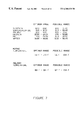
- FIG. 7 is a table listing the elements forming the composition of matter for the instant invention and showing both the possible range and the preferred range of the separate constituents for the composition of matter.
- FIG. 8 is a copy of a chart made during the stimulation of a well showing the series of pressure changes and associated fluid flow that occur as the formation associated with a given perforation opens and is then sealed by a ball. Notations on the chart, made by the operator, show what is happening.
- FIG. 9A is sketch of the one of the apparatuses used to “pressure-test” seal balls using the instant composition of matter.
- FIG. 9B is an expanded view of the test chamber.
- FIG. 10A is a simplified sketch of a hydraulic fracturing operation showing the wellbore, a vertical fracture and penetration of the fracturing fluid into the formation with additional penetration into the formations above and below the production zone.
- FIG. 10B is a simplified sketch of the fluid loss additive forming a filter cake against the pores of the formation.
- FIG. 11 is a sketch of the test apparatus used to demonstrate the properties of the fluid loss additive.
- FIG. 12A is a table showing the laboratory comparison results between standard starch and the instant invention.
- FIG. 12B is a graph showing laboratory regained permeability results (cleanup) for standard starch and the instant invention.
- the preferred mixture to injection mold the ball sealer and/or fluid loss additive of the present invention comprises a soluble filler material and adhesives that when combined, and allowed to cure, will provide the required neutral mass and strength for ball sealer and/or fluid loss additive that forms the instant invention.
- the filler material consists of glycerin, wintergreen oil, oxyzolidine, oil (animal, vegetable or mineral), and water.
- the preferred oxyzolidine is ZOLDINE® basically 5-HYDROXYMETHYL-1-AZA-3,7-DIOXABICYCLO (3,3,0) OCTANE (55%) and WATER (45%). Other fillers may be added as needed and as explained later in this disclosure.
- the adhesive consists basically of collagen.
- the mixture is prepared by blending the collagen with the other elements in a proper ratio, as explained later in this disclosure, to form a viscous slurry suitable for injection molding or pouring into thin slabs.
- the mixture is thermosetting because of the combined properties of the constituents forming the composition of matter.
- dyes at the time of mixing the slurry to indicate the specific gravity and/or the solubility time for the composition of matter forming the ball sealer.
- the prototype balls have a specific gravity in the range between 1.1 to 1.2 and ideally should have a specific gravity close to the fluid being used in the wellbore so that the balls will almost, but not quite, float in the wellbore fluid.
- the viscous slurry must be carefully controlled for two reasons. First the dry slurry must have suitable properties for injection molding equipment, and second the composition of matter must, after injection molding and curing, exhibit the required properties expected of a ball sealer. It is known that glycerin and oil serve almost a similar function within the mixture.
- the oil preferably mineral oil; however almost any heavy petroleum product or animal or vegetable oils may be used) serves to elongate the dissolution time when the ball is in the wellbore. Glycerin helps stabilize the ball during curing and can be replaced with oil.
- the slurry is mixed in a carefully controlled temperature range varying between 56 to 214 degrees Fahrenheit and allowed to set up.
- the composition is then ground (a standard operation in the injection molding process) to a suitable size that allows the composition of matter to be fed to an injection molding machine containing a mold.
- the mold should have the form required for the particular ball size. Standard injection molding techniques are used, and any person who is skilled in the art of injection molding will be able to produce the balls; however, care must be taken in feeding the injection molding machine with the composition. It has been noted that relative humidity affects the operation, but a skilled operator can take the daily changes into account.
- the mold will generally produce a plurality of balls and may be changed out to produce ball of various diameters. Standard mold manufacturing techniques are employed, and any person with skill in the art will be able to produce a suitable mold for an injection molding machine.
- the mold temperature is held between 67 to 214 degrees Fahrenheit, and the injection pressure ranges between 100 to 2,000 PSI. (Those familiar with the art of injection molding know that pressure and injection temperature are interrelated. It is important to maintain the stated temperature range.) The temperature range is again dependent on relative humidity, and a skilled operator will be able to make the necessary adjustments.
- the formed ball(s) is(are) held within the mold cavity for a sufficient period of time to assure that thermosetting takes place.
- the mold is opened and the seal balls are removed and sent to storage for additional curing of at least two weeks.
- the actual curing time varies because the thermosetting composition will form a tight (few voids) surface about the ball itself, thus, limiting the rate that residual moisture can leave the body of the ball.
- the ball is fully cured when it will not distort or flatten under external pressure. Basically, a person can feel when the ball is cured, because finger nails will not penetrate the surface nor will the ball feel soft. Furthermore, when dropped, a properly cured ball will bounce like a marble.
- a plurality of degradable ball sealers having a mass between 0.25 to 1.25 ounces is produced.
- the diameter may be changed by changing the mold and should be chosen to meet the sealing condition that the ball perform under. (I.e., seal perforations or seal tubing.)
- the resulting ball (see FIG. 2) comprises a round, solid, smooth surfaced seal ball with suitable characteristics that allow it to soften slightly on its surface in the presence of the stimulating fluid; thus, assuring a solid contact, through controlled surface deformation, on the edges of the casing perforation. (See FIG. 3)
- the ball retains its strength until the stimulation operation is complete.
- the optimum composition of matter namely the dried slurry mixture sent to the injection molding operation—the mixing temperature, and the molding temperature were determined through a series of trial and error testing. For example, if the slurry is mixed at too low a temperature, it was found that the ingredients would not properly mix and a weak ball resulted. On the other hand if the slurry was mixed at a very high temperature, the collagen would break down which also resulted in a weak ball.
- the inventors define a “weak ball” to be one that will not hold up in a wellbore (see FIG. 1) when plugging a perforation.
- other filler materials may be used within the ball sealer and experience has shown that fiber glass threads may be incorporated into the slurry prior to injection molding.
- the fiber glass provides additional strength to the ball in high temperature/high pressure conditions and stops the ball from deforming within the perforation. A deformed ball often passes through the perforation and into the formation; thus, reducing the efficiency of the overall fracturing operation.
- ball sealers the presence of minute threads of fiber glass, after the ball sealers degrade within the wellbore, is NOT detrimental as the wellbore fluids do NOT enter the formation being part of the produced fluids that return to the surface.
- any fiber which exhibits similar properties to fiber glass may be used. In fact, cotton or some form of degradable fiber could be employed. Ball strength testing, or pressure testing, was performed in a pressure jig (see FIG.
- FIG. 5 shows the results of one of a series of tests.
- four balls were placed in stimulation fluid held at room temperature (approximately 72° F.) for a long time. The balls were removed from the fluid and the diameter measured with a caliper. The starting diameter for the balls was approximately 0.89 inches.
- the wellbore temperature will return to the downhole ambient temperature. This increase in temperature that the ball sealers experience and their tendency to naturally go into solution in wellbore fluids will cause them to degrade and go into solution within several hours.
- the optimum mixture was determined by pressure testing (weakness) and dissolution testing. The optimum mixture is shown in FIG. 7 . In a similar manner the optimum molding temperature was found by trial and error. The optimum temperature range is shown in FIG. 7 . In the injection molding process, because injection pressure and mold temperature are interrelated, the injection process is run between 100 and 2000 PSI and the mold temperature is held to between 83 and 184 degrees Fahrenheit.
- ball sealer (1) that is capable of diverting fluid flow from casing perforations which are in communication with highly permeable strata to perforations which are in communication with low permeability strata, (2) that will readily degrade in the stimulation fluid at the elevated temperatures found in wellbores but only after the stimulation process is complete, (3) that will degrade by becoming soluble in the fluids found in wellbores, (4) that is capable of deformation to conform to an irregular-shaped casing perforation, and (5) that retains its strength and does not extrude through a perforation casing while the stimulation process is underway.
- ball sealers manufactured from the composition of matter and using the techniques disclosed meet the objectives of the disclosure.
- a bridge plug is a device which is set in a wellbore and completely isolates one portion of the wellbore from another.
- the bridge plug can be removed by wire-line operations or by drilling it out.
- the operator In a multiple zone well, the operator generally starts at the bottom of well and sets a packer above the zone to be stimulated. Stimulation operations for the lowest section then commence. Standard ball sealers are used with the fluid. Once the lower section is stimulated, a bridge plug is set at a point just below the next zone to be treated with the packer set just above the zone to be treated.
- Stimulation operations for this zone are then commenced. Standard balls are again used with the stimulating fluid. This process is repeated until the entire 2000 ft zone was treated.
- the operator goes back in the well and drills out the bridge plugs. The operator often experiences a series of problems associated with the seal balls remaining in the wellbore.
- One operator in fact refuses to use ball sealers and bridge plugs because of the problems associated with the remaining seal balls.
- the operator attempts to stimulate a zone through high rate stimulation in the hopes that high fluid flow rate will open up low permeability section even though fluid is passing into other sections. The success is limited, but the operator does not have to contend with problems during the subsequent drilling operations.
- the prototype balls were manufactured with a specific gravity within the range 1.1 to 1.2. This range must not be read as a limitation for the composition of matter used to manufacture the balls may be adjusted to produce a range that falls within 0.5 to 2.0.
- the balls may be lightened by using a light weight filler such as pearlite.
- the balls may be made heavier by using a heavy weight filler such as sand.
- the filler elements that may be used to adjust specific gravity is limited only by the wellbore conditions and one's imagination. Wellbore conditions would limit the choice of filler because one would not want to use a filler that would or could damage the formation, add an unnecessarily hazardous material, etc.
- a production tubing is often run from the surface to the production zone (or zones) and the tubing is isolated from the casing. It is often necessary to pressure test the tubing and a steel ball is allowed to travel to the bottom of the tubing where it will seal the tubing. Pressure is then applied and the integrity of the tubing may be determined. Once this test is complete, the steel ball must be recovered. This is usually done by reverse flowing fluid down the casing and back up the production tubing while hoping that the ball will travel back to the surface. Often the ball stays in the tubing, which means that the entire string must be removed. A ball using manufactured from the instant composition of matter can easily be used in place of the steel ball. Pressure testing may be done and then time and temperature with degrade the ball; thus' opening up the tubing for production.
- the fluid loss additive is manufactured in one of two ways.
- First ball sealers which fail quality control i.e., out of round, etc.
- the basic ingredients may be mixed together with 10 percent water by volume at 150 degrees Fahrenheit for about one hour.
- the resulting elastic material is then stretched into sheets about 1 ⁇ 4-inch thick and dried in an oven (or kiln) at about 200 degrees Fahrenheit for at least one hour.
- the powder can be mixed with oil or refined oils (such as diesel fuel, corn oils, and the like) and sold in drums.
- the liquid additive would be mixed with the fracturing fluid and used in the standard industry manner.
- the fluid loss additive may be mixed with standard fluid loss additives, such as starch. A mix of these materials may result in reduced cleanup, compared to a pure inhibitor, but will certainly result in an improvement over the current art.
- the instant invention has undergone extensive testing in the laboratory and compared to standard starch.
- the fluid-loss inhibitor of the instant invention comprising a mixture of collagen or industrial gelatin (95%), glycerol or glycerin (4%), wintergreen oil or methylsalicylate (0.3%), oxyzolidine (0.2%), and corn oil (0.2%) (although any oil animal, vegetable or mineral could be used), were mixed with about 10% volume of water.
- the preferred oxyzolidine is ZOLDINE® basically 5-HYDROXYMETHYL-1-AZA-3,7-DIOXABICYCLO (3,3,0) OCTANE (55%) and WATER (45%).
- the mixture was mixed in a dough mixer at 150 degrees Fahrenheit, drawn into elastic sheets of about 1 ⁇ 4-inch thickness, dried in an oven at about 200degrees Fahrenheit for about one hour. It was then broken into chunks and ground into a ⁇ 80 mesh +270 mesh powder. Tests were then performed on a 4 milli Darcys (mD) outcrop sandstone to evaluate the comparative performance of the instant biodegradable fluid loss system, starch and silica flower. Static leak off tests were run at 2000 psi, 150 degrees Fahrenheit using a generic 30 lb/1000 gallons linear guar (polymer) solution.
- the core samples were brine saturated in a 2% KCl solution and placed in the test jig shown in FIG. 11 . For simplicity, only one core holder is shown; however, the comparison tests were run concurrently.
- the fracturing fluid was then prepared:
- Biocide 0.1 gm/1000 gallons (g/tg)
- the fluid was then split and the different fluid loss inhibitor additives added to each sample.
- Starch at 25 lb/tg was used in one core and the instant invention at 25 lb/tg was used in the second core.
- Static leak off was run for 60 minutes at 2000 psi, 150 degrees Fahrenheit.
- the fluid then flowed through the bypass line, the system pressurized, and the leak off valve opened.
- a gas accumulator, pre-charged to 2000 psi kept the system pressure at 2000 psi during initial leak off.
- test system(s) was (were) shut in for 12 hours.
- FIGS. 12A and 12B The results of these tests is summarized in FIGS. 12A and 12B. Essentially an initial 18% clean-up was achieved for the starch inhibitor with damage attributed to the guar solution. The subsequent ammonium persulphate breaker squeeze increased clean-up to 61.5% In the case of the instant invention an initial 27.4%% clean-up was achieved with damage attributed to the guar solution. The subsequent ammonium persulphate breaker squeeze increased clean-up to 80.7%. (A significant improvement.)
Abstract
Description
Claims (10)
Priority Applications (1)
| Application Number | Priority Date | Filing Date | Title |
|---|---|---|---|
| US09/444,901 US6380138B1 (en) | 1999-04-06 | 1999-11-22 | Injection molded degradable casing perforation ball sealers fluid loss additive and method of use |
Applications Claiming Priority (2)
| Application Number | Priority Date | Filing Date | Title |
|---|---|---|---|
| US5554999A | 1999-04-06 | 1999-04-06 | |
| US09/444,901 US6380138B1 (en) | 1999-04-06 | 1999-11-22 | Injection molded degradable casing perforation ball sealers fluid loss additive and method of use |
Related Parent Applications (1)
| Application Number | Title | Priority Date | Filing Date |
|---|---|---|---|
| US5554999A Continuation-In-Part | 1999-04-06 | 1999-04-06 |
Publications (1)
| Publication Number | Publication Date |
|---|---|
| US6380138B1 true US6380138B1 (en) | 2002-04-30 |
Family
ID=21998599
Family Applications (1)
| Application Number | Title | Priority Date | Filing Date |
|---|---|---|---|
| US09/444,901 Expired - Lifetime US6380138B1 (en) | 1999-04-06 | 1999-11-22 | Injection molded degradable casing perforation ball sealers fluid loss additive and method of use |
Country Status (1)
| Country | Link |
|---|---|
| US (1) | US6380138B1 (en) |
Cited By (94)
| Publication number | Priority date | Publication date | Assignee | Title |
|---|---|---|---|---|
| US20030106690A1 (en) * | 2001-10-31 | 2003-06-12 | Boney Curtis L. | Methods for controlling screenouts |
| US20040214724A1 (en) * | 2001-06-11 | 2004-10-28 | Todd Bradley L. | Compositions and methods for reducing the viscosity of a fluid |
| US20040261996A1 (en) * | 2003-06-27 | 2004-12-30 | Trinidad Munoz | Methods of diverting treating fluids in subterranean zones and degradable diverting materials |
| US20050034868A1 (en) * | 2003-08-14 | 2005-02-17 | Frost Keith A. | Orthoester compositions and methods of use in subterranean applications |
| US20050034865A1 (en) * | 2003-08-14 | 2005-02-17 | Todd Bradley L. | Compositions and methods for degrading filter cake |
| US20050045328A1 (en) * | 2001-06-11 | 2005-03-03 | Frost Keith A. | Orthoester compositions and methods for reducing the viscosified treatment fluids |
| US20050059558A1 (en) * | 2003-06-27 | 2005-03-17 | Blauch Matthew E. | Methods for improving proppant pack permeability and fracture conductivity in a subterranean well |
| US20050059556A1 (en) * | 2003-09-17 | 2005-03-17 | Trinidad Munoz | Treatment fluids and methods of use in subterranean formations |
| US20050126780A1 (en) * | 2003-06-27 | 2005-06-16 | Halliburton Energy Services, Inc. | Compositions and methods for improving fracture conductivity in a subterranean well |
| US20050126785A1 (en) * | 2003-12-15 | 2005-06-16 | Todd Bradley L. | Filter cake degradation compositions and methods of use in subterranean operations |
| US20050130848A1 (en) * | 2003-06-27 | 2005-06-16 | Halliburton Energy Services, Inc. | Compositions and methods for improving fracture conductivity in a subterranean well |
| US20050161220A1 (en) * | 2004-01-27 | 2005-07-28 | Todd Bradley L. | Fluid loss control additives for use in fracturing subterranean formations |
| US20050167105A1 (en) * | 2004-01-30 | 2005-08-04 | Roddy Craig W. | Contained micro-particles for use in well bore operations |
| US20050167104A1 (en) * | 2004-01-30 | 2005-08-04 | Roddy Craig W. | Compositions and methods for the delivery of chemical components in subterranean well bores |
| US20050183741A1 (en) * | 2004-02-20 | 2005-08-25 | Surjaatmadja Jim B. | Methods of cleaning and cutting using jetted fluids |
| US20050194141A1 (en) * | 2004-03-04 | 2005-09-08 | Fairmount Minerals, Ltd. | Soluble fibers for use in resin coated proppant |
| US20050205258A1 (en) * | 2004-03-17 | 2005-09-22 | Reddy B R | Cement compositions containing degradable materials and methods of cementing in subterranean formations |
| WO2005090745A1 (en) * | 2004-03-18 | 2005-09-29 | Vincent Marcantonio | Multizone stimulation using wax balls |
| US20060021753A1 (en) * | 2004-07-30 | 2006-02-02 | Key Energy Services, Inc. | Method of Pumping an "In-the-Formation" Diverting Agent in a Lateral Section of an Oil and Gas Well |
| US20060032633A1 (en) * | 2004-08-10 | 2006-02-16 | Nguyen Philip D | Methods and compositions for carrier fluids comprising water-absorbent fibers |
| US20060048938A1 (en) * | 2004-09-03 | 2006-03-09 | Kalman Mark D | Carbon foam particulates and methods of using carbon foam particulates in subterranean applications |
| US7033976B2 (en) | 2003-01-06 | 2006-04-25 | M-I L.L.C. | Fluid system additive |
| US20060113077A1 (en) * | 2004-09-01 | 2006-06-01 | Dean Willberg | Degradable material assisted diversion or isolation |
| US20060169451A1 (en) * | 2005-02-01 | 2006-08-03 | Halliburton Energy Services, Inc. | Self-degrading cement compositions and methods of using self-degrading cement compositions in subterranean formations |
| US20060172893A1 (en) * | 2005-01-28 | 2006-08-03 | Halliburton Energy Services, Inc. | Methods and compositions relating to the hydrolysis of water-hydrolysable materials |
| US20060172894A1 (en) * | 2005-02-02 | 2006-08-03 | Halliburton Energy Services, Inc. | Degradable particulate generation and associated methods |
| US20060172989A1 (en) * | 2005-02-02 | 2006-08-03 | Michael Konkel | Aminoalkoxyphenyl indolone derivatives |
| US20060169182A1 (en) * | 2005-01-28 | 2006-08-03 | Halliburton Energy Services, Inc. | Methods and compositions relating to the hydrolysis of water-hydrolysable materials |
| US20060169449A1 (en) * | 2005-01-31 | 2006-08-03 | Halliburton Energy Services, Inc. | Self-degrading fibers and associated methods of use and manufacture |
| US20060175059A1 (en) * | 2005-01-21 | 2006-08-10 | Sinclair A R | Soluble deverting agents |
| US20060185847A1 (en) * | 2005-02-22 | 2006-08-24 | Halliburton Energy Services, Inc. | Methods of placing treatment chemicals |
| US20060185848A1 (en) * | 2005-02-22 | 2006-08-24 | Halliburton Energy Services, Inc. | Fracturing fluids comprising degradable diverting agents and methods of use in subterranean formations |
| US20060254774A1 (en) * | 2005-05-12 | 2006-11-16 | Halliburton Energy Services, Inc. | Degradable surfactants and methods for use |
| US20060258543A1 (en) * | 2005-05-12 | 2006-11-16 | Halliburton Energy Services, Inc. | Degradable surfactants and methods for use cross-reference to related applications |
| US20060258544A1 (en) * | 2005-05-12 | 2006-11-16 | Halliburton Energy Services, Inc. | Degradable surfactants and methods for use |
| US20060272554A1 (en) * | 2005-06-02 | 2006-12-07 | Jardine Leslie A | Biomass-derived grinding aids |
| US20060283597A1 (en) * | 2003-08-14 | 2006-12-21 | Halliburton Energy Services, Inc. | Methods of degrading filter cakes in a subterranean formation |
| US20070049501A1 (en) * | 2005-09-01 | 2007-03-01 | Halliburton Energy Services, Inc. | Fluid-loss control pills comprising breakers that comprise orthoesters and/or poly(orthoesters) and methods of use |
| US20070169935A1 (en) * | 2005-12-19 | 2007-07-26 | Fairmount Minerals, Ltd. | Degradable ball sealers and methods for use in well treatment |
| US20070169938A1 (en) * | 2006-01-20 | 2007-07-26 | Halliburton Energy Services, Inc. | Methods of controlled acidization in a wellbore |
| US20080009423A1 (en) * | 2005-01-31 | 2008-01-10 | Halliburton Energy Services, Inc. | Self-degrading fibers and associated methods of use and manufacture |
| US20080047707A1 (en) * | 2006-08-25 | 2008-02-28 | Curtis Boney | Method and system for treating a subterranean formation |
| US20080078547A1 (en) * | 2006-10-02 | 2008-04-03 | Sinclair A Richard | Proppants with soluble composite coatings |
| US20080078549A1 (en) * | 2006-09-29 | 2008-04-03 | Halliburton Energy Services, Inc. | Methods and Compositions Relating to the Control of the Rates of Acid-Generating Compounds in Acidizing Operations |
| WO2008050286A1 (en) * | 2006-10-24 | 2008-05-02 | Schlumberger Canada Limited | Degradable material assisted diversion |
| US20080169099A1 (en) * | 2007-01-15 | 2008-07-17 | Schlumberger Technology Corporation | Method for Controlling the Flow of Fluid Between a Downhole Formation and a Base Pipe |
| US20080200352A1 (en) * | 2004-09-01 | 2008-08-21 | Willberg Dean M | Degradable Material Assisted Diversion or Isolation |
| WO2009050681A2 (en) * | 2007-10-18 | 2009-04-23 | Schlumberger Canada Limited | Multilayered ball sealer and method of use thereof |
| US20090255674A1 (en) * | 2008-04-15 | 2009-10-15 | Boney Curtis L | Sealing By Ball Sealers |
| US7648946B2 (en) | 2004-11-17 | 2010-01-19 | Halliburton Energy Services, Inc. | Methods of degrading filter cakes in subterranean formations |
| US7674753B2 (en) | 2003-09-17 | 2010-03-09 | Halliburton Energy Services, Inc. | Treatment fluids and methods of forming degradable filter cakes comprising aliphatic polyester and their use in subterranean formations |
| US7678742B2 (en) | 2006-09-20 | 2010-03-16 | Halliburton Energy Services, Inc. | Drill-in fluids and associated methods |
| US7678743B2 (en) | 2006-09-20 | 2010-03-16 | Halliburton Energy Services, Inc. | Drill-in fluids and associated methods |
| US7686080B2 (en) | 2006-11-09 | 2010-03-30 | Halliburton Energy Services, Inc. | Acid-generating fluid loss control additives and associated methods |
| US7687438B2 (en) | 2006-09-20 | 2010-03-30 | Halliburton Energy Services, Inc. | Drill-in fluids and associated methods |
| US7700525B2 (en) | 2005-09-22 | 2010-04-20 | Halliburton Energy Services, Inc. | Orthoester-based surfactants and associated methods |
| US20100200235A1 (en) * | 2009-02-11 | 2010-08-12 | Halliburton Energy Services, Inc. | Degradable perforation balls and associated methods of use in subterranean applications |
| US7833944B2 (en) | 2003-09-17 | 2010-11-16 | Halliburton Energy Services, Inc. | Methods and compositions using crosslinked aliphatic polyesters in well bore applications |
| US7833943B2 (en) | 2008-09-26 | 2010-11-16 | Halliburton Energy Services Inc. | Microemulsifiers and methods of making and using same |
| US7906464B2 (en) | 2008-05-13 | 2011-03-15 | Halliburton Energy Services, Inc. | Compositions and methods for the removal of oil-based filtercakes |
| WO2011041628A2 (en) | 2009-10-02 | 2011-04-07 | Technisand, Inc. | Meta crosslinked benzyl polymers |
| US20110127727A1 (en) * | 2008-07-11 | 2011-06-02 | Welltec A/S | Sealing arrangement and sealing method |
| US7998910B2 (en) | 2009-02-24 | 2011-08-16 | Halliburton Energy Services, Inc. | Treatment fluids comprising relative permeability modifiers and methods of use |
| US8006760B2 (en) | 2008-04-10 | 2011-08-30 | Halliburton Energy Services, Inc. | Clean fluid systems for partial monolayer fracturing |
| US20110221137A1 (en) * | 2008-11-20 | 2011-09-15 | Udoka Obi | Sealing method and apparatus |
| US20110226479A1 (en) * | 2008-04-15 | 2011-09-22 | Philipp Tippel | Diversion by combining dissolvable and degradable particles and fibers |
| US8082992B2 (en) | 2009-07-13 | 2011-12-27 | Halliburton Energy Services, Inc. | Methods of fluid-controlled geometry stimulation |
| US20120067447A1 (en) * | 2009-04-16 | 2012-03-22 | Nicholas John Ryan | Delivery method and compositions |
| US8220548B2 (en) | 2007-01-12 | 2012-07-17 | Halliburton Energy Services Inc. | Surfactant wash treatment fluids and associated methods |
| WO2012125196A1 (en) * | 2011-03-14 | 2012-09-20 | Geneeral Plastics & Composites, Lp | Composite frac ball |
| US8329621B2 (en) | 2006-07-25 | 2012-12-11 | Halliburton Energy Services, Inc. | Degradable particulates and associated methods |
| US20130186625A1 (en) * | 2012-01-20 | 2013-07-25 | Baker Hughes Incorporated | Refracturing Method for Plug and Perforate Wells |
| US8541051B2 (en) | 2003-08-14 | 2013-09-24 | Halliburton Energy Services, Inc. | On-the fly coating of acid-releasing degradable material onto a particulate |
| US8561696B2 (en) | 2008-11-18 | 2013-10-22 | Schlumberger Technology Corporation | Method of placing ball sealers for fluid diversion |
| US20130292123A1 (en) * | 2009-02-11 | 2013-11-07 | Halliburton Energy Services, Inc. | Degradable Balls for Use in Subterranean Applications |
| US8598092B2 (en) | 2005-02-02 | 2013-12-03 | Halliburton Energy Services, Inc. | Methods of preparing degradable materials and methods of use in subterranean formations |
| US8657002B2 (en) | 2005-06-20 | 2014-02-25 | Schlumberger Technology Corporation | Degradable fiber systems for stimulation |
| WO2014193697A1 (en) * | 2013-05-31 | 2014-12-04 | Halliburton Energy Services, Inc. | Degradable balls for use in subterranean applications |
| WO2015031018A1 (en) * | 2013-08-27 | 2015-03-05 | Schlumberger Canada Limited | Swellable ball sealers |
| US9090810B2 (en) | 2010-12-14 | 2015-07-28 | Altarock Energy, Inc. | High temperature temporary diverter and lost circulation material |
| CN104832126A (en) * | 2015-05-15 | 2015-08-12 | 中国石油集团渤海钻探工程有限公司 | Anti-pollution well cementation method suitable for two stage and drilling liner cementation |
| US9133689B2 (en) | 2010-10-15 | 2015-09-15 | Schlumberger Technology Corporation | Sleeve valve |
| CN105765162A (en) * | 2013-11-27 | 2016-07-13 | 贝克休斯公司 | System and method for re-fracturing multizone horizontal wellbores |
| CN106401480A (en) * | 2016-11-29 | 2017-02-15 | 中国石油天然气股份有限公司 | Technology combining horizontal drilling and profile control blocking |
| US20170260827A1 (en) * | 2016-03-10 | 2017-09-14 | Marty Hill Hopkins | Degradable downhole tools and\or components thereof, method of hydraulic fracturing using such tools or components, and method of making such tools or components |
| US9765592B2 (en) | 2012-06-06 | 2017-09-19 | Exxonmobil Upstream Research Company | Systems and methods for secondary sealing of a perforation within a wellbore casing |
| US10280703B2 (en) | 2003-05-15 | 2019-05-07 | Kureha Corporation | Applications of degradable polymer for delayed mechanical changes in wells |
| CN110043222A (en) * | 2019-04-26 | 2019-07-23 | 天津市玛特瑞科技有限公司 | A kind of retardance magnesium alloy completion tool cosolvent with and preparation method thereof |
| WO2020061463A1 (en) | 2018-09-20 | 2020-03-26 | Conocophillips Company | Dissolvable thread tape and plugs for wells |
| US10738559B2 (en) | 2014-06-13 | 2020-08-11 | Halliburton Energy Services, Inc. | Downhole tools comprising composite sealing elements |
| US10808162B2 (en) | 2017-11-17 | 2020-10-20 | Fairmount Santrol Inc. | Crush resistant buoyant ball sealers |
| US11136461B2 (en) | 2014-12-22 | 2021-10-05 | Schlumberger Technology Corporation | Degradable composite structures |
| CN114032079A (en) * | 2021-03-25 | 2022-02-11 | 中国石油天然气集团有限公司 | Consolidation type temporary plugging agent and temporary plugging method |
| US11891458B2 (en) | 2017-08-22 | 2024-02-06 | China Petroleum & Chemical Corporation | Starch-containing microsphere and preparation method and use thereof |
Citations (14)
| Publication number | Priority date | Publication date | Assignee | Title |
|---|---|---|---|---|
| US3319716A (en) | 1965-10-21 | 1967-05-16 | Halliburton Co | Fluid loss additive for well fluids, composition and process |
| US3971852A (en) | 1973-06-12 | 1976-07-27 | Polak's Frutal Works, Inc. | Process of encapsulating an oil and product produced thereby |
| US4064055A (en) | 1974-08-27 | 1977-12-20 | Halliburton Company | Aqueous drilling fluids and additives therefor |
| US4387769A (en) | 1981-08-10 | 1983-06-14 | Exxon Production Research Co. | Method for reducing the permeability of subterranean formations |
| US4526695A (en) | 1981-08-10 | 1985-07-02 | Exxon Production Research Co. | Composition for reducing the permeability of subterranean formations |
| US4716964A (en) | 1981-08-10 | 1988-01-05 | Exxon Production Research Company | Use of degradable ball sealers to seal casing perforations in well treatment fluid diversion |
| US5032297A (en) | 1989-05-19 | 1991-07-16 | Nalco Chemical Company | Enzymatically degradable fluid loss additive |
| US5246602A (en) | 1986-02-24 | 1993-09-21 | Forrest Gabriel T | Method and composition fracturing subterranean formations |
| US5253709A (en) | 1990-01-29 | 1993-10-19 | Conoco Inc. | Method and apparatus for sealing pipe perforations |
| US5301751A (en) | 1992-10-21 | 1994-04-12 | Githens Charles J | Method for using soap as a soluable fluid loss additive in the hydraulic fracturing treatment of oil and gas wells |
| US5354786A (en) | 1991-06-20 | 1994-10-11 | Shell Oil Company | Fluid loss control composition |
| US5356149A (en) | 1992-12-23 | 1994-10-18 | Kane Patrick E | Injection molded water-soluble golf ball |
| US5415228A (en) | 1993-12-07 | 1995-05-16 | Schlumberger Technology Corporation - Dowell Division | Fluid loss control additives for use with gravel pack placement fluids |
| US5439057A (en) | 1994-04-29 | 1995-08-08 | Halliburton Company | Method for controlling fluid loss in high permeability formations |
-
1999
- 1999-11-22 US US09/444,901 patent/US6380138B1/en not_active Expired - Lifetime
Patent Citations (14)
| Publication number | Priority date | Publication date | Assignee | Title |
|---|---|---|---|---|
| US3319716A (en) | 1965-10-21 | 1967-05-16 | Halliburton Co | Fluid loss additive for well fluids, composition and process |
| US3971852A (en) | 1973-06-12 | 1976-07-27 | Polak's Frutal Works, Inc. | Process of encapsulating an oil and product produced thereby |
| US4064055A (en) | 1974-08-27 | 1977-12-20 | Halliburton Company | Aqueous drilling fluids and additives therefor |
| US4387769A (en) | 1981-08-10 | 1983-06-14 | Exxon Production Research Co. | Method for reducing the permeability of subterranean formations |
| US4526695A (en) | 1981-08-10 | 1985-07-02 | Exxon Production Research Co. | Composition for reducing the permeability of subterranean formations |
| US4716964A (en) | 1981-08-10 | 1988-01-05 | Exxon Production Research Company | Use of degradable ball sealers to seal casing perforations in well treatment fluid diversion |
| US5246602A (en) | 1986-02-24 | 1993-09-21 | Forrest Gabriel T | Method and composition fracturing subterranean formations |
| US5032297A (en) | 1989-05-19 | 1991-07-16 | Nalco Chemical Company | Enzymatically degradable fluid loss additive |
| US5253709A (en) | 1990-01-29 | 1993-10-19 | Conoco Inc. | Method and apparatus for sealing pipe perforations |
| US5354786A (en) | 1991-06-20 | 1994-10-11 | Shell Oil Company | Fluid loss control composition |
| US5301751A (en) | 1992-10-21 | 1994-04-12 | Githens Charles J | Method for using soap as a soluable fluid loss additive in the hydraulic fracturing treatment of oil and gas wells |
| US5356149A (en) | 1992-12-23 | 1994-10-18 | Kane Patrick E | Injection molded water-soluble golf ball |
| US5415228A (en) | 1993-12-07 | 1995-05-16 | Schlumberger Technology Corporation - Dowell Division | Fluid loss control additives for use with gravel pack placement fluids |
| US5439057A (en) | 1994-04-29 | 1995-08-08 | Halliburton Company | Method for controlling fluid loss in high permeability formations |
Cited By (151)
| Publication number | Priority date | Publication date | Assignee | Title |
|---|---|---|---|---|
| US20050045328A1 (en) * | 2001-06-11 | 2005-03-03 | Frost Keith A. | Orthoester compositions and methods for reducing the viscosified treatment fluids |
| US20040214724A1 (en) * | 2001-06-11 | 2004-10-28 | Todd Bradley L. | Compositions and methods for reducing the viscosity of a fluid |
| US20030106690A1 (en) * | 2001-10-31 | 2003-06-12 | Boney Curtis L. | Methods for controlling screenouts |
| US6938693B2 (en) * | 2001-10-31 | 2005-09-06 | Schlumberger Technology Corporation | Methods for controlling screenouts |
| US7033976B2 (en) | 2003-01-06 | 2006-04-25 | M-I L.L.C. | Fluid system additive |
| US10280703B2 (en) | 2003-05-15 | 2019-05-07 | Kureha Corporation | Applications of degradable polymer for delayed mechanical changes in wells |
| US20050130848A1 (en) * | 2003-06-27 | 2005-06-16 | Halliburton Energy Services, Inc. | Compositions and methods for improving fracture conductivity in a subterranean well |
| US20050059558A1 (en) * | 2003-06-27 | 2005-03-17 | Blauch Matthew E. | Methods for improving proppant pack permeability and fracture conductivity in a subterranean well |
| US20050126780A1 (en) * | 2003-06-27 | 2005-06-16 | Halliburton Energy Services, Inc. | Compositions and methods for improving fracture conductivity in a subterranean well |
| WO2005003514A1 (en) * | 2003-06-27 | 2005-01-13 | Halliburton Energy Services, Inc. | Methods of diverting treating fluids in subterranean zones and degradable diverting materials |
| US7036587B2 (en) | 2003-06-27 | 2006-05-02 | Halliburton Energy Services, Inc. | Methods of diverting treating fluids in subterranean zones and degradable diverting materials |
| US20040261996A1 (en) * | 2003-06-27 | 2004-12-30 | Trinidad Munoz | Methods of diverting treating fluids in subterranean zones and degradable diverting materials |
| US20050034865A1 (en) * | 2003-08-14 | 2005-02-17 | Todd Bradley L. | Compositions and methods for degrading filter cake |
| US20060283597A1 (en) * | 2003-08-14 | 2006-12-21 | Halliburton Energy Services, Inc. | Methods of degrading filter cakes in a subterranean formation |
| US8541051B2 (en) | 2003-08-14 | 2013-09-24 | Halliburton Energy Services, Inc. | On-the fly coating of acid-releasing degradable material onto a particulate |
| US20050034868A1 (en) * | 2003-08-14 | 2005-02-17 | Frost Keith A. | Orthoester compositions and methods of use in subterranean applications |
| US20050059557A1 (en) * | 2003-09-17 | 2005-03-17 | Todd Bradley L. | Subterranean treatment fluids and methods of treating subterranean formations |
| US7833944B2 (en) | 2003-09-17 | 2010-11-16 | Halliburton Energy Services, Inc. | Methods and compositions using crosslinked aliphatic polyesters in well bore applications |
| US20050059556A1 (en) * | 2003-09-17 | 2005-03-17 | Trinidad Munoz | Treatment fluids and methods of use in subterranean formations |
| US7674753B2 (en) | 2003-09-17 | 2010-03-09 | Halliburton Energy Services, Inc. | Treatment fluids and methods of forming degradable filter cakes comprising aliphatic polyester and their use in subterranean formations |
| US7829507B2 (en) | 2003-09-17 | 2010-11-09 | Halliburton Energy Services Inc. | Subterranean treatment fluids comprising a degradable bridging agent and methods of treating subterranean formations |
| US20050126785A1 (en) * | 2003-12-15 | 2005-06-16 | Todd Bradley L. | Filter cake degradation compositions and methods of use in subterranean operations |
| US20050161220A1 (en) * | 2004-01-27 | 2005-07-28 | Todd Bradley L. | Fluid loss control additives for use in fracturing subterranean formations |
| US7096947B2 (en) * | 2004-01-27 | 2006-08-29 | Halliburton Energy Services, Inc. | Fluid loss control additives for use in fracturing subterranean formations |
| US20050167105A1 (en) * | 2004-01-30 | 2005-08-04 | Roddy Craig W. | Contained micro-particles for use in well bore operations |
| US7204312B2 (en) | 2004-01-30 | 2007-04-17 | Halliburton Energy Services, Inc. | Compositions and methods for the delivery of chemical components in subterranean well bores |
| US20050167104A1 (en) * | 2004-01-30 | 2005-08-04 | Roddy Craig W. | Compositions and methods for the delivery of chemical components in subterranean well bores |
| US20050183741A1 (en) * | 2004-02-20 | 2005-08-25 | Surjaatmadja Jim B. | Methods of cleaning and cutting using jetted fluids |
| US20050194141A1 (en) * | 2004-03-04 | 2005-09-08 | Fairmount Minerals, Ltd. | Soluble fibers for use in resin coated proppant |
| US7244492B2 (en) | 2004-03-04 | 2007-07-17 | Fairmount Minerals, Ltd. | Soluble fibers for use in resin coated proppant |
| US7172022B2 (en) | 2004-03-17 | 2007-02-06 | Halliburton Energy Services, Inc. | Cement compositions containing degradable materials and methods of cementing in subterranean formations |
| US20050205258A1 (en) * | 2004-03-17 | 2005-09-22 | Reddy B R | Cement compositions containing degradable materials and methods of cementing in subterranean formations |
| US20070100029A1 (en) * | 2004-03-17 | 2007-05-03 | Reddy B R | Cement compositions containing degradable materials and methods of cementing in subterranean formations |
| WO2005090745A1 (en) * | 2004-03-18 | 2005-09-29 | Vincent Marcantonio | Multizone stimulation using wax balls |
| US20080004190A1 (en) * | 2004-03-18 | 2008-01-03 | Vincent Marcantonio | Multizone Stimulation Using Wax Balls |
| US7273104B2 (en) | 2004-07-30 | 2007-09-25 | Key Energy Services, Inc. | Method of pumping an “in-the-formation” diverting agent in a lateral section of an oil and gas well |
| US20060021753A1 (en) * | 2004-07-30 | 2006-02-02 | Key Energy Services, Inc. | Method of Pumping an "In-the-Formation" Diverting Agent in a Lateral Section of an Oil and Gas Well |
| US20060032633A1 (en) * | 2004-08-10 | 2006-02-16 | Nguyen Philip D | Methods and compositions for carrier fluids comprising water-absorbent fibers |
| US20080200352A1 (en) * | 2004-09-01 | 2008-08-21 | Willberg Dean M | Degradable Material Assisted Diversion or Isolation |
| US7380600B2 (en) * | 2004-09-01 | 2008-06-03 | Schlumberger Technology Corporation | Degradable material assisted diversion or isolation |
| US20060113077A1 (en) * | 2004-09-01 | 2006-06-01 | Dean Willberg | Degradable material assisted diversion or isolation |
| US8167043B2 (en) | 2004-09-01 | 2012-05-01 | Schlumberger Technology Corporation | Degradable material assisted diversion or isolation |
| US20080289823A1 (en) * | 2004-09-01 | 2008-11-27 | Willberg Dean M | Degradable Material Assisted Diversion or Isolation |
| US7775278B2 (en) | 2004-09-01 | 2010-08-17 | Schlumberger Technology Corporation | Degradable material assisted diversion or isolation |
| US20060048938A1 (en) * | 2004-09-03 | 2006-03-09 | Kalman Mark D | Carbon foam particulates and methods of using carbon foam particulates in subterranean applications |
| US7648946B2 (en) | 2004-11-17 | 2010-01-19 | Halliburton Energy Services, Inc. | Methods of degrading filter cakes in subterranean formations |
| US20060175059A1 (en) * | 2005-01-21 | 2006-08-10 | Sinclair A R | Soluble deverting agents |
| US20060169182A1 (en) * | 2005-01-28 | 2006-08-03 | Halliburton Energy Services, Inc. | Methods and compositions relating to the hydrolysis of water-hydrolysable materials |
| US20060172893A1 (en) * | 2005-01-28 | 2006-08-03 | Halliburton Energy Services, Inc. | Methods and compositions relating to the hydrolysis of water-hydrolysable materials |
| US8030249B2 (en) | 2005-01-28 | 2011-10-04 | Halliburton Energy Services, Inc. | Methods and compositions relating to the hydrolysis of water-hydrolysable materials |
| US8030251B2 (en) | 2005-01-28 | 2011-10-04 | Halliburton Energy Services, Inc. | Methods and compositions relating to the hydrolysis of water-hydrolysable materials |
| US20060169449A1 (en) * | 2005-01-31 | 2006-08-03 | Halliburton Energy Services, Inc. | Self-degrading fibers and associated methods of use and manufacture |
| US8188013B2 (en) | 2005-01-31 | 2012-05-29 | Halliburton Energy Services, Inc. | Self-degrading fibers and associated methods of use and manufacture |
| US20080009423A1 (en) * | 2005-01-31 | 2008-01-10 | Halliburton Energy Services, Inc. | Self-degrading fibers and associated methods of use and manufacture |
| US20060169451A1 (en) * | 2005-02-01 | 2006-08-03 | Halliburton Energy Services, Inc. | Self-degrading cement compositions and methods of using self-degrading cement compositions in subterranean formations |
| US20060172894A1 (en) * | 2005-02-02 | 2006-08-03 | Halliburton Energy Services, Inc. | Degradable particulate generation and associated methods |
| US20060172989A1 (en) * | 2005-02-02 | 2006-08-03 | Michael Konkel | Aminoalkoxyphenyl indolone derivatives |
| US8598092B2 (en) | 2005-02-02 | 2013-12-03 | Halliburton Energy Services, Inc. | Methods of preparing degradable materials and methods of use in subterranean formations |
| US20060185848A1 (en) * | 2005-02-22 | 2006-08-24 | Halliburton Energy Services, Inc. | Fracturing fluids comprising degradable diverting agents and methods of use in subterranean formations |
| US20060185847A1 (en) * | 2005-02-22 | 2006-08-24 | Halliburton Energy Services, Inc. | Methods of placing treatment chemicals |
| US20060254774A1 (en) * | 2005-05-12 | 2006-11-16 | Halliburton Energy Services, Inc. | Degradable surfactants and methods for use |
| US20060258543A1 (en) * | 2005-05-12 | 2006-11-16 | Halliburton Energy Services, Inc. | Degradable surfactants and methods for use cross-reference to related applications |
| US7662753B2 (en) | 2005-05-12 | 2010-02-16 | Halliburton Energy Services, Inc. | Degradable surfactants and methods for use |
| US20060258544A1 (en) * | 2005-05-12 | 2006-11-16 | Halliburton Energy Services, Inc. | Degradable surfactants and methods for use |
| US7677315B2 (en) | 2005-05-12 | 2010-03-16 | Halliburton Energy Services, Inc. | Degradable surfactants and methods for use |
| US9328021B2 (en) | 2005-06-02 | 2016-05-03 | Gcp Applied Technologies Inc. | Biomass derived grinding aids |
| US20060272554A1 (en) * | 2005-06-02 | 2006-12-07 | Jardine Leslie A | Biomass-derived grinding aids |
| US20110146540A1 (en) * | 2005-06-02 | 2011-06-23 | Jardine Leslie A | Biomass-derived grinding aids |
| US7922811B2 (en) | 2005-06-02 | 2011-04-12 | W. R. Grace & Co.-Conn. | Biomass-derived grinding aids |
| US8657002B2 (en) | 2005-06-20 | 2014-02-25 | Schlumberger Technology Corporation | Degradable fiber systems for stimulation |
| US20070049501A1 (en) * | 2005-09-01 | 2007-03-01 | Halliburton Energy Services, Inc. | Fluid-loss control pills comprising breakers that comprise orthoesters and/or poly(orthoesters) and methods of use |
| US7713916B2 (en) | 2005-09-22 | 2010-05-11 | Halliburton Energy Services, Inc. | Orthoester-based surfactants and associated methods |
| US7700525B2 (en) | 2005-09-22 | 2010-04-20 | Halliburton Energy Services, Inc. | Orthoester-based surfactants and associated methods |
| US7647964B2 (en) * | 2005-12-19 | 2010-01-19 | Fairmount Minerals, Ltd. | Degradable ball sealers and methods for use in well treatment |
| US20070169935A1 (en) * | 2005-12-19 | 2007-07-26 | Fairmount Minerals, Ltd. | Degradable ball sealers and methods for use in well treatment |
| US20070169938A1 (en) * | 2006-01-20 | 2007-07-26 | Halliburton Energy Services, Inc. | Methods of controlled acidization in a wellbore |
| US8329621B2 (en) | 2006-07-25 | 2012-12-11 | Halliburton Energy Services, Inc. | Degradable particulates and associated methods |
| US20080047707A1 (en) * | 2006-08-25 | 2008-02-28 | Curtis Boney | Method and system for treating a subterranean formation |
| US8281860B2 (en) * | 2006-08-25 | 2012-10-09 | Schlumberger Technology Corporation | Method and system for treating a subterranean formation |
| US7678743B2 (en) | 2006-09-20 | 2010-03-16 | Halliburton Energy Services, Inc. | Drill-in fluids and associated methods |
| US7687438B2 (en) | 2006-09-20 | 2010-03-30 | Halliburton Energy Services, Inc. | Drill-in fluids and associated methods |
| US7678742B2 (en) | 2006-09-20 | 2010-03-16 | Halliburton Energy Services, Inc. | Drill-in fluids and associated methods |
| US20080078549A1 (en) * | 2006-09-29 | 2008-04-03 | Halliburton Energy Services, Inc. | Methods and Compositions Relating to the Control of the Rates of Acid-Generating Compounds in Acidizing Operations |
| US7490667B2 (en) | 2006-10-02 | 2009-02-17 | Fairmount Minerals, Inc. | Proppants with soluble composite coatings |
| US20080078547A1 (en) * | 2006-10-02 | 2008-04-03 | Sinclair A Richard | Proppants with soluble composite coatings |
| WO2008050286A1 (en) * | 2006-10-24 | 2008-05-02 | Schlumberger Canada Limited | Degradable material assisted diversion |
| US7565929B2 (en) | 2006-10-24 | 2009-07-28 | Schlumberger Technology Corporation | Degradable material assisted diversion |
| DE112007002575T5 (en) | 2006-10-24 | 2009-11-19 | Schlumberger Technology B.V. | Redirection supported with degradable material |
| GB2455672A (en) * | 2006-10-24 | 2009-06-24 | Schlumberger Holdings | Degradable material assisted diversion |
| US7686080B2 (en) | 2006-11-09 | 2010-03-30 | Halliburton Energy Services, Inc. | Acid-generating fluid loss control additives and associated methods |
| US8220548B2 (en) | 2007-01-12 | 2012-07-17 | Halliburton Energy Services Inc. | Surfactant wash treatment fluids and associated methods |
| US20080169099A1 (en) * | 2007-01-15 | 2008-07-17 | Schlumberger Technology Corporation | Method for Controlling the Flow of Fluid Between a Downhole Formation and a Base Pipe |
| US7832473B2 (en) * | 2007-01-15 | 2010-11-16 | Schlumberger Technology Corporation | Method for controlling the flow of fluid between a downhole formation and a base pipe |
| US20090101334A1 (en) * | 2007-10-18 | 2009-04-23 | Belgin Baser | Multilayered ball sealer and method of use thereof |
| WO2009050681A2 (en) * | 2007-10-18 | 2009-04-23 | Schlumberger Canada Limited | Multilayered ball sealer and method of use thereof |
| US8714250B2 (en) | 2007-10-18 | 2014-05-06 | Schlumberger Technology Corporation | Multilayered ball sealer and method of use thereof |
| WO2009050681A3 (en) * | 2007-10-18 | 2009-09-03 | Schlumberger Canada Limited | Multilayered ball sealer and method of use thereof |
| RU2485286C2 (en) * | 2007-10-18 | 2013-06-20 | Шлюмбергер Текнолоджи Б.В. | Method and multi-layer ball-type seal for insulation of perforations in well |
| US8006760B2 (en) | 2008-04-10 | 2011-08-30 | Halliburton Energy Services, Inc. | Clean fluid systems for partial monolayer fracturing |
| US9316087B2 (en) | 2008-04-15 | 2016-04-19 | Schlumberger Technology Corporation | Sealing by ball sealers |
| US9212535B2 (en) | 2008-04-15 | 2015-12-15 | Schlumberger Technology Corporation | Diversion by combining dissolvable and degradable particles and fibers |
| US8936085B2 (en) * | 2008-04-15 | 2015-01-20 | Schlumberger Technology Corporation | Sealing by ball sealers |
| RU2470141C2 (en) * | 2008-04-15 | 2012-12-20 | Шлюмбергер Текнолоджи Б.В. | Method of improving perforation by sealing balls |
| US20110226479A1 (en) * | 2008-04-15 | 2011-09-22 | Philipp Tippel | Diversion by combining dissolvable and degradable particles and fibers |
| US20090255674A1 (en) * | 2008-04-15 | 2009-10-15 | Boney Curtis L | Sealing By Ball Sealers |
| US7906464B2 (en) | 2008-05-13 | 2011-03-15 | Halliburton Energy Services, Inc. | Compositions and methods for the removal of oil-based filtercakes |
| US20110127727A1 (en) * | 2008-07-11 | 2011-06-02 | Welltec A/S | Sealing arrangement and sealing method |
| US7833943B2 (en) | 2008-09-26 | 2010-11-16 | Halliburton Energy Services Inc. | Microemulsifiers and methods of making and using same |
| US7960314B2 (en) | 2008-09-26 | 2011-06-14 | Halliburton Energy Services Inc. | Microemulsifiers and methods of making and using same |
| US8561696B2 (en) | 2008-11-18 | 2013-10-22 | Schlumberger Technology Corporation | Method of placing ball sealers for fluid diversion |
| US20110221137A1 (en) * | 2008-11-20 | 2011-09-15 | Udoka Obi | Sealing method and apparatus |
| US20130292123A1 (en) * | 2009-02-11 | 2013-11-07 | Halliburton Energy Services, Inc. | Degradable Balls for Use in Subterranean Applications |
| US9260935B2 (en) * | 2009-02-11 | 2016-02-16 | Halliburton Energy Services, Inc. | Degradable balls for use in subterranean applications |
| US20100200235A1 (en) * | 2009-02-11 | 2010-08-12 | Halliburton Energy Services, Inc. | Degradable perforation balls and associated methods of use in subterranean applications |
| EP2396382B1 (en) * | 2009-02-11 | 2014-04-16 | Halliburton Energy Services, Inc. | Degradable perforation balls and associated methods of use in subterranean applications |
| US9926483B2 (en) | 2009-02-11 | 2018-03-27 | Halliburton Energy Services, Inc. | Degradable balls for use in subterranean applications |
| US8757260B2 (en) * | 2009-02-11 | 2014-06-24 | Halliburton Energy Services, Inc. | Degradable perforation balls and associated methods of use in subterranean applications |
| AU2010212653B2 (en) * | 2009-02-11 | 2014-07-10 | Halliburton Energy Services, Inc. | Degradable perforation balls and associated methods of use in subterranean applications |
| US20120214715A1 (en) * | 2009-02-11 | 2012-08-23 | Halliburton Energy Services, Inc. | Degradable Perforation Balls and Associated Methods of Use in Subterranean Applications |
| US8936084B2 (en) * | 2009-02-11 | 2015-01-20 | Halliburton Energy Services, Inc. | Degradable perforation balls and associated methods of use in subterranean applications |
| US7998910B2 (en) | 2009-02-24 | 2011-08-16 | Halliburton Energy Services, Inc. | Treatment fluids comprising relative permeability modifiers and methods of use |
| US8950438B2 (en) * | 2009-04-16 | 2015-02-10 | Brinker Technology Ltd | Method and compositions for delivery of a concentrated quantity of sealing elements to a leak site in a vessel |
| US20120067447A1 (en) * | 2009-04-16 | 2012-03-22 | Nicholas John Ryan | Delivery method and compositions |
| US8082992B2 (en) | 2009-07-13 | 2011-12-27 | Halliburton Energy Services, Inc. | Methods of fluid-controlled geometry stimulation |
| WO2011041628A2 (en) | 2009-10-02 | 2011-04-07 | Technisand, Inc. | Meta crosslinked benzyl polymers |
| US9371715B2 (en) | 2010-10-15 | 2016-06-21 | Schlumberger Technology Corporation | Downhole extending ports |
| US9133689B2 (en) | 2010-10-15 | 2015-09-15 | Schlumberger Technology Corporation | Sleeve valve |
| US9090810B2 (en) | 2010-12-14 | 2015-07-28 | Altarock Energy, Inc. | High temperature temporary diverter and lost circulation material |
| WO2012125196A1 (en) * | 2011-03-14 | 2012-09-20 | Geneeral Plastics & Composites, Lp | Composite frac ball |
| US20130186625A1 (en) * | 2012-01-20 | 2013-07-25 | Baker Hughes Incorporated | Refracturing Method for Plug and Perforate Wells |
| US8857513B2 (en) * | 2012-01-20 | 2014-10-14 | Baker Hughes Incorporated | Refracturing method for plug and perforate wells |
| US9765592B2 (en) | 2012-06-06 | 2017-09-19 | Exxonmobil Upstream Research Company | Systems and methods for secondary sealing of a perforation within a wellbore casing |
| GB2528798A (en) * | 2013-05-31 | 2016-02-03 | Halliburton Energy Services Inc | Degradable balls for use in subterranean applications |
| GB2528798B (en) * | 2013-05-31 | 2017-04-05 | Halliburton Energy Services Inc | Degradable balls for use in subterranean applications |
| WO2014193697A1 (en) * | 2013-05-31 | 2014-12-04 | Halliburton Energy Services, Inc. | Degradable balls for use in subterranean applications |
| AU2014271873B2 (en) * | 2013-05-31 | 2016-11-17 | Halliburton Energy Services, Inc. | Degradable balls for use in subterranean applications |
| WO2015031018A1 (en) * | 2013-08-27 | 2015-03-05 | Schlumberger Canada Limited | Swellable ball sealers |
| CN105765162B (en) * | 2013-11-27 | 2019-11-19 | 贝克休斯公司 | System and method for pressure break Multi sectional horizontal wellbore again |
| CN105765162A (en) * | 2013-11-27 | 2016-07-13 | 贝克休斯公司 | System and method for re-fracturing multizone horizontal wellbores |
| US10738559B2 (en) | 2014-06-13 | 2020-08-11 | Halliburton Energy Services, Inc. | Downhole tools comprising composite sealing elements |
| US11136461B2 (en) | 2014-12-22 | 2021-10-05 | Schlumberger Technology Corporation | Degradable composite structures |
| CN104832126A (en) * | 2015-05-15 | 2015-08-12 | 中国石油集团渤海钻探工程有限公司 | Anti-pollution well cementation method suitable for two stage and drilling liner cementation |
| US10508525B2 (en) * | 2016-03-10 | 2019-12-17 | Bubbletight, LLC | Degradable downhole tools and\or components thereof, method of hydraulic fracturing using such tools or components, and method of making such tools or components |
| US20170260827A1 (en) * | 2016-03-10 | 2017-09-14 | Marty Hill Hopkins | Degradable downhole tools and\or components thereof, method of hydraulic fracturing using such tools or components, and method of making such tools or components |
| CN106401480A (en) * | 2016-11-29 | 2017-02-15 | 中国石油天然气股份有限公司 | Technology combining horizontal drilling and profile control blocking |
| US11891458B2 (en) | 2017-08-22 | 2024-02-06 | China Petroleum & Chemical Corporation | Starch-containing microsphere and preparation method and use thereof |
| US10808162B2 (en) | 2017-11-17 | 2020-10-20 | Fairmount Santrol Inc. | Crush resistant buoyant ball sealers |
| WO2020061463A1 (en) | 2018-09-20 | 2020-03-26 | Conocophillips Company | Dissolvable thread tape and plugs for wells |
| US11053762B2 (en) | 2018-09-20 | 2021-07-06 | Conocophillips Company | Dissolvable thread tape and plugs for wells |
| CN110043222A (en) * | 2019-04-26 | 2019-07-23 | 天津市玛特瑞科技有限公司 | A kind of retardance magnesium alloy completion tool cosolvent with and preparation method thereof |
| CN114032079A (en) * | 2021-03-25 | 2022-02-11 | 中国石油天然气集团有限公司 | Consolidation type temporary plugging agent and temporary plugging method |
Similar Documents
| Publication | Publication Date | Title |
|---|---|---|
| US6380138B1 (en) | Injection molded degradable casing perforation ball sealers fluid loss additive and method of use | |
| CA2320949C (en) | Injection molded degradable casing perforation ball sealers | |
| US6165947A (en) | Method and composition for controlling fluid loss in high permeability hydrocarbon bearing formations | |
| US4662448A (en) | Well treatment method using sodium silicate to seal formation | |
| RU2307144C2 (en) | Non-harmful liquid for reducing absorption of drill mud and method for application thereof | |
| CA2595686C (en) | Soluble diverting agents | |
| US3747681A (en) | Hydraulic fracturing process using polyethylene oxide based fracturing fluid | |
| CA2617279C (en) | Methods of forming packs in a plurality of perforations in a casing of a wellbore | |
| CN103352683B (en) | The water conservancy diversion of degradation material auxiliary or isolation | |
| CA2746567C (en) | In-situ solidification of invert emulsion fluids to form gas tight annular barrier | |
| US20140290943A1 (en) | Stabilized Fluids In Well Treatment | |
| RU2530141C2 (en) | Method for treatment of well bore having annular insulating system | |
| US11920080B2 (en) | Plasticized polyvinyl alcohol diverter materials | |
| US20090111718A1 (en) | Control of Fines Migration In Well Treatments | |
| MX2012013299A (en) | Hydraulic fracturing method. | |
| US20160280983A1 (en) | Fluid diversion system for well treatment operations | |
| US3654992A (en) | Fracturing method | |
| US20100093891A1 (en) | Self-Viscosifying and Self-Breaking Gels | |
| WO2011161569A2 (en) | Composition and methods for oilfield application | |
| US3630280A (en) | Method and composition for treating subterranean formations | |
| US20230136892A1 (en) | Pelletized Diverting Agents Using Degradable Polymers | |
| US10982126B2 (en) | Chemical packer composition and methods of using same for isolation of water/gas zones | |
| US20190309217A1 (en) | Amaranth grain particulates for diversion applications | |
| WO2017097925A1 (en) | Environmentally friendly wellbore consolidating/fluid loss material | |
| US11254860B2 (en) | Diversion using solid particulates |
Legal Events
| Date | Code | Title | Description |
|---|---|---|---|
| STCF | Information on status: patent grant |
Free format text: PATENTED CASE |
|
| AS | Assignment |
Owner name: NATIONAL CITY BANK, OHIO Free format text: SECURITY AGREEMENT;ASSIGNOR:FAIRMOUNT MINERALS, LTD.;REEL/FRAME:014438/0192 Effective date: 20030313 |
|
| AS | Assignment |
Owner name: NATIONAL CITY BANK, OHIO Free format text: RE-RECORD TO ADD OMITTED ASSIGNORS' NAME, ON A DOCUMENT PREVIOUSLY RECORDED ON REEL 014438 FRAME 0192;ASSIGNORS:FAIRMOUNT MINERALS, LTD.;BEST SAND CORPORATION;BEST SAND OF PENNSYLVANIA, INC.;AND OTHERS;REEL/FRAME:015156/0334 Effective date: 20030313 |
|
| FEPP | Fee payment procedure |
Free format text: PAT HOLDER CLAIMS SMALL ENTITY STATUS, ENTITY STATUS SET TO SMALL (ORIGINAL EVENT CODE: LTOS); ENTITY STATUS OF PATENT OWNER: LARGE ENTITY |
|
| FPAY | Fee payment |
Year of fee payment: 4 |
|
| AS | Assignment |
Owner name: BEST SAND OF PENNSYLVANIA, INC., OHIO Free format text: RELEASE OF SECURITY INTEREST;ASSIGNOR:NATIONAL CITY BANK;REEL/FRAME:020462/0752 Effective date: 20080131 Owner name: D.M. BOYD COMPANY, L.L.C., OHIO Free format text: RELEASE OF SECURITY INTEREST;ASSIGNOR:NATIONAL CITY BANK;REEL/FRAME:020462/0752 Effective date: 20080131 Owner name: SPECIALTY SANDS, INC., OHIO Free format text: RELEASE OF SECURITY INTEREST;ASSIGNOR:NATIONAL CITY BANK;REEL/FRAME:020462/0752 Effective date: 20080131 Owner name: STANDARD SAND CORPORATION, OHIO Free format text: RELEASE OF SECURITY INTEREST;ASSIGNOR:NATIONAL CITY BANK;REEL/FRAME:020462/0752 Effective date: 20080131 Owner name: FAIRMOUNT MINERALS SALES DE MEXICO, S. DE R.L. DE Free format text: RELEASE OF SECURITY INTEREST;ASSIGNOR:NATIONAL CITY BANK;REEL/FRAME:020462/0752 Effective date: 20080131 Owner name: MINERAL VISIONS INC., OHIO Free format text: RELEASE OF SECURITY INTEREST;ASSIGNOR:NATIONAL CITY BANK;REEL/FRAME:020462/0752 Effective date: 20080131 Owner name: TECHNISAND, INC., OHIO Free format text: RELEASE OF SECURITY INTEREST;ASSIGNOR:NATIONAL CITY BANK;REEL/FRAME:020462/0752 Effective date: 20080131 Owner name: FML HOLDINGS, INC., OHIO Free format text: RELEASE OF SECURITY INTEREST;ASSIGNOR:NATIONAL CITY BANK;REEL/FRAME:020462/0752 Effective date: 20080131 Owner name: WEDRON SILICA COMPANY, OHIO Free format text: RELEASE OF SECURITY INTEREST;ASSIGNOR:NATIONAL CITY BANK;REEL/FRAME:020462/0752 Effective date: 20080131 Owner name: CONSTRUCTION AGGREGATES CORPORATION OF MICHIGAN, I Free format text: RELEASE OF SECURITY INTEREST;ASSIGNOR:NATIONAL CITY BANK;REEL/FRAME:020462/0752 Effective date: 20080131 Owner name: FAIRMOUNT MINERALS, LTD., OHIO Free format text: RELEASE OF SECURITY INTEREST;ASSIGNOR:NATIONAL CITY BANK;REEL/FRAME:020462/0752 Effective date: 20080131 Owner name: WEXFORD SAND CO., OHIO Free format text: RELEASE OF SECURITY INTEREST;ASSIGNOR:NATIONAL CITY BANK;REEL/FRAME:020462/0752 Effective date: 20080131 Owner name: BEST SAND CORPORATION, OHIO Free format text: RELEASE OF SECURITY INTEREST;ASSIGNOR:NATIONAL CITY BANK;REEL/FRAME:020462/0752 Effective date: 20080131 Owner name: CHEYENNE SAND CORP., OHIO Free format text: RELEASE OF SECURITY INTEREST;ASSIGNOR:NATIONAL CITY BANK;REEL/FRAME:020462/0752 Effective date: 20080131 Owner name: WISCONSIN INDUSTRIAL SAND COMPANY, L.L.C., OHIO Free format text: RELEASE OF SECURITY INTEREST;ASSIGNOR:NATIONAL CITY BANK;REEL/FRAME:020462/0752 Effective date: 20080131 Owner name: WISCONSIN SPECIALTY SANDS, INC., OHIO Free format text: RELEASE OF SECURITY INTEREST;ASSIGNOR:NATIONAL CITY BANK;REEL/FRAME:020462/0752 Effective date: 20080131 |
|
| FEPP | Fee payment procedure |
Free format text: PAYOR NUMBER ASSIGNED (ORIGINAL EVENT CODE: ASPN); ENTITY STATUS OF PATENT OWNER: LARGE ENTITY |
|
| FPAY | Fee payment |
Year of fee payment: 8 |
|
| AS | Assignment |
Owner name: BARCLAYS BANK PLC, AS COLLATERAL AGENT, NEW YORK Free format text: PATENT SECURITY AGREEMENT;ASSIGNOR:FAIRMOUNT MINERALS, LTD.;REEL/FRAME:024804/0940 Effective date: 20100805 |
|
| FEPP | Fee payment procedure |
Free format text: PAT HOLDER NO LONGER CLAIMS SMALL ENTITY STATUS, ENTITY STATUS SET TO UNDISCOUNTED (ORIGINAL EVENT CODE: STOL); ENTITY STATUS OF PATENT OWNER: LARGE ENTITY |
|
| FEPP | Fee payment procedure |
Free format text: PAYER NUMBER DE-ASSIGNED (ORIGINAL EVENT CODE: RMPN); ENTITY STATUS OF PATENT OWNER: LARGE ENTITY Free format text: PAYOR NUMBER ASSIGNED (ORIGINAL EVENT CODE: ASPN); ENTITY STATUS OF PATENT OWNER: LARGE ENTITY |
|
| FPAY | Fee payment |
Year of fee payment: 12 |
|
| SULP | Surcharge for late payment | ||
| AS | Assignment |
Owner name: FAIRMOUNT SANTROL INC., OHIO Free format text: CHANGE OF NAME;ASSIGNOR:FAIRMOUNT MINERALS, LTD.;REEL/FRAME:034013/0803 Effective date: 20140814 |
|
| AS | Assignment |
Owner name: FAIRMOUNT SANTROL INC. (F/K/A FAIRMOUNT MINERALS, Free format text: RELEASE OF SECURITY INTEREST IN PATENTS FILED AT R/F 024804/0940;ASSIGNOR:BARCLAYS BANK PLC;REEL/FRAME:044348/0220 Effective date: 20171031 |
|
| AS | Assignment |
Owner name: BARCLAYS BANK PLC, NEW YORK Free format text: SECURITY INTEREST;ASSIGNOR:FAIRMOUNT SANTROL INC.;REEL/FRAME:044014/0757 Effective date: 20171031 |
|
| AS | Assignment |
Owner name: PNC BANK, NATIONAL ASSOCIATION, PENNSYLVANIA Free format text: SECURITY INTEREST;ASSIGNORS:FAIRMOUNT SANTROL INC.;SELF-SUSPENDING PROPPANT LLC;TECHNISAND, INC.;REEL/FRAME:044040/0380 Effective date: 20171101 |
|
| AS | Assignment |
Owner name: FAIRMOUNT SANTROL, INC., OHIO Free format text: RELEASE BY SECURED PARTY;ASSIGNOR:BARCLAYS BANK PLC;REEL/FRAME:046036/0619 Effective date: 20180601 Owner name: FAIRMOUNT SANTROL INC., OHIO Free format text: RELEASE BY SECURED PARTY;ASSIGNOR:PNC BANK, NATIONAL ASSOCIATION;REEL/FRAME:046036/0699 Effective date: 20180601 |