US6398564B1 - Communication connector for compact computer devices - Google Patents
Communication connector for compact computer devices Download PDFInfo
- Publication number
- US6398564B1 US6398564B1 US09/416,095 US41609599A US6398564B1 US 6398564 B1 US6398564 B1 US 6398564B1 US 41609599 A US41609599 A US 41609599A US 6398564 B1 US6398564 B1 US 6398564B1
- Authority
- US
- United States
- Prior art keywords
- connector
- receptacle structure
- platform
- receptacle
- communication
- Prior art date
- Legal status (The legal status is an assumption and is not a legal conclusion. Google has not performed a legal analysis and makes no representation as to the accuracy of the status listed.)
- Expired - Lifetime
Links
Images


Classifications
-
- H—ELECTRICITY
- H01—ELECTRIC ELEMENTS
- H01R—ELECTRICALLY-CONDUCTIVE CONNECTIONS; STRUCTURAL ASSOCIATIONS OF A PLURALITY OF MUTUALLY-INSULATED ELECTRICAL CONNECTING ELEMENTS; COUPLING DEVICES; CURRENT COLLECTORS
- H01R13/00—Details of coupling devices of the kinds covered by groups H01R12/70 or H01R24/00 - H01R33/00
- H01R13/62—Means for facilitating engagement or disengagement of coupling parts or for holding them in engagement
- H01R13/639—Additional means for holding or locking coupling parts together, after engagement, e.g. separate keylock, retainer strap
-
- H—ELECTRICITY
- H01—ELECTRIC ELEMENTS
- H01R—ELECTRICALLY-CONDUCTIVE CONNECTIONS; STRUCTURAL ASSOCIATIONS OF A PLURALITY OF MUTUALLY-INSULATED ELECTRICAL CONNECTING ELEMENTS; COUPLING DEVICES; CURRENT COLLECTORS
- H01R24/00—Two-part coupling devices, or either of their cooperating parts, characterised by their overall structure
- H01R24/60—Contacts spaced along planar side wall transverse to longitudinal axis of engagement
- H01R24/62—Sliding engagements with one side only, e.g. modular jack coupling devices
Definitions
- This invention relates to the field of connectors for computers and devices for computers.
- the invention relates to a connector for coupling a communication line to a computer.
- Communication plugs are used to establish communications between computers and other computers, local area networks and/or wide-area networks such as the Internet.
- computers connect to a phone jack having a RJ-style connector to access the Internet or an email server on a network.
- Increasingly, more diverse and compact computers incorporate communication capabilities for communication lines using plug-style connectors.
- computer devices including handheld computers, such as Palm PilotTM organizers, laptop computers, and PCMCIA standard communication cards, may include RJ-style plugs for coupling the respective device to a phone or Ethernet line.
- Some computing devices integrate a female connector to mate with a communication plug in a horizontal direction.
- laptop computers often have a jack for receiving a RJ plug.
- Laptop computers usually include the jack on a side surface of the device.
- the thickness of a laptop computer is usually relatively small, causing the jack to be positioned close to the underlying surface in which the lap top computer rests on.
- some computers such as the Sony VAIOTM computer employ a hinged female connector for mating to a communication plug.
- the hinged connector is accessible from a surface of the computer to receive a phone or Ethernet plug in a direction horizontal to the underlying surface that the computer rests on.
- the hinged extension is slanted with respect to the side of the computer so that the communication plug must be received at an angle.
- the exterior surface of the device is minimized to preserve size. Available surface space is often used to retain buttons for operating the device, a display screen, a microphone/speaker, and connectors for coupling the device to other computers and accessories.
- the thickness and compactness of the handheld computer is also an important design consideration.
- PCMCIA cards are used to adapt certain computers for coupling with a communication line having a communication plug such an RJ-style plug.
- PCMCIA cards include Type I, Type II, and Type III cards.
- Type I and Type II cards in particular are constrained from incorporating a jack for a phone line because the relative size of such PCMCIA cards is mandated by industry standards to be less than 5 millimeters. Since RJ-style plugs are larger than 5 millimeters, these types of PCMCIA cards use additional adapters to couple to a RJ-style plug or Ethernet jack.
- some PCMCIA cards for computers incorporate a connector as a retractable extension from a housing of the card.
- the connectors can be extended from the housing of the card to receive the RJ plug in a direction vertical to the planar dimensions of the PCMCIA card. This allows the computing device to incorporate the cross-sectional of the female RJ connector in a lateral direction, thereby minimizing exterior real estate needed for the female RJ connector.
- These devices are usually used with compact computers that have limited vertical dimensions.
- a connector is provided to mate with communication plug that extends a communication line such as a phone line or Ethernet line.
- the connector is provided on a platform that is extendable from a surface of a housing that retains the connector.
- the connector also includes a receptacle structure that is moveably coupled to the platform. When the platform is extended, the receptacle structure may be raised to receive the communication plug in a horizontal direction with respect to the platform. When the connector is lowered, the platform can be retracted into the housing to be stored.
- the connector is adapted to mate with a communication plug such as a RJ-11 or RJ-45 connector.
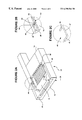
- FIG. 1 is an isometric view of a connector having a platform aligned to receive a body of a communication connector that extends a communication line, with a receptacle structure being raised to receive the connector, under an embodiment of the invention.
- FIGS. 2A-2C illustrate the connector with the receptacle structure in a lowered position to be stored in a housing, under an embodiment of the invention.
- FIG. 2A illustrates the receptacle structure is the lowered position with respect to the platform.
- FIG. 2B is a close-up of FIG. 2A showing a coupling that moveable couples the receptacle structure to the platform, under an embodiment of the invention.
- FIG. 2C is a close-up of FIG. 2B showing the coupling isolated from the connector, under an embodiment of the invention.
- FIG. 3 illustrates a communication connector for extending a communication line to be coupled to a connector, under an embodiment of the invention.
- FIGS. 4A-4B illustrate a platform of the connector moveably coupled to a housing to extend and retract into the housing.
- FIG. 4A illustrates one embodiment in which the platform may be extended from the housing, with a retracted position of the platform being shown in phantom.
- FIG. 4B illustrates another embodiment in which the platform may be extended from or retracted into the housing.
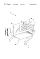
- FIG. 5 illustrates a printed circuit card device, under an embodiment of the invention.
- FIG. 6 illustrates a computer device, under an embodiment of the invention.
- Embodiments of the invention include a female connector for mating with a plug-type communication connector such as a RJ jack.
- a platform forms an extension of a computer or computer device to receive a communication plug.
- the connector includes a receptacle structure that is moveably coupled to the platform to move between a raised position and a lowered position. When the receptacle structure is raised, the plug-type communication connector may be received by and secured to the receptacle structure in a direction parallel to the platform. Connector elements on the connector are positioned on the platform to contact mating elements of the plug-type connector. When the receptacle structure is disengaged from the plug-type connector, the receptacle structure may be lowered towards the platform to reduce the size of the connector. In one embodiment, the connector may then be fitted into a housing of a device, such as a compact computer or a PCMCIA card.
- the connector extends from and retracts into a housing of a device.
- the connector receives the plug-type connector in a horizontal direction with respect to the platform of the connector.
- the plug-type connector can be inserted into the connector in a horizontal direction, while enabling the connector to be stored within a housing of the device as if it where aligned to receive the communication plug in a vertical direction.
- the orientation of the connector when stored minimizes a vertical thickness of the region in the housing dedicated to the connector. As a result, this embodiment can be employed in devices that have a relatively small vertical thickness, such as CompactFlash cards, thin lap top computers and handheld computers. The orientation of the connector enables the connector to be completely retracted into the housing of such devices until the connector is needed.
- Previous connectors that couple computers to communication lines are usually fitted into a relatively cramped dimension of a computer.
- such computer either couple to the connector using a PCMCIA card, or include the connector as an integral component of the computer.
- computers extend known connectors in close proximity to an underlying surface of the computer.
- users are required to insert the communication plug vertically into the communication connector when the connector is in close proximity to the underlying surface.
- the proximity of the underlying surface limits the clearence available for inserting the communication plug.
- the communication plug sometimes contacts the underlying surface prior to the communication plug being secured to the connector, resulting in a misconnection between the communication plug and the connector.
- embodiments of the invention receive the communication plug horizontally with respect to the underlying surface, thereby avoiding the vertical clearance problem of previous devices.
- Embodiments of the invention provide a connector that receives the communication plug in a direction horizontal to the underlying surface, thereby avoiding the creation of a moment that can tilt the computer or bend the platform of the connector.
- hinged connector that can be extended from a side of the computer to receive a communication plug.
- the hinged connector includes a storage area within the housing having dimensions to accommodate an upright RJ-11 connector.
- an embodiment of the invention allows for the connector to be folded into a non-upright or lateral position to be retracted into a housing of a computer or computer device. This allows the connector under an embodiment of the invention to be used with computer devices such as handheld computers, PCMCIA cards, and CompactFlash cards.
- the hinges on such devices are too mechanically intricate.
- FIG. 1 illustrates a female communication connector 100 for coupling a computer device to a communication line such as phone or Ethernet line.
- the communication connector 100 is adapted to receive an exterior body 65 of a communication plug 60 (shown in FIG. 4) that terminates the communication line.
- the connector 100 includes a platform 10 having a front end 12 for receiving the body 65 of the communication plug 60 , and a back end 14 .
- a recess 15 is positioned between the front end 12 and back end 14 and provides access to a pin block 40 having a plurality of connector elements 38 .
- the connector 100 includes a receptacle structure 20 , shown in a raised position and moveable to a lowered position (shown in FIG. 2 ).
- the receptacle structure 20 includes an opening 30 that is contoured to mate with a body 65 of the plug 60 .
- the receptacle structure 20 receives the body 65 of the communication plug 60 in a direction parallel or horizontal to the platform 10 . This orientation coincides with the communication plug 60 being inserted horizontally with respect to an underlying surface of a computer or computer device housing the platform 10 .
- connector elements 38 of the pin block 40 establish communications between the connector 100 and the communication plug 60 .
- communication plugs include any connective device including an exterior body housing or retaining connector elements that inserts at least partially into a receptacle so that one or more connector elements can communicate with elements of an opposing connector.
- Communication plugs for use under an embodiment of the invention include known modular jack or media communication connectors, including RJ series connector such as an RJ-11 connector typically used with phone lines, 6-pin miniature modular plugs, 8-pin miniature modular plugs, and coaxial cables.
- the exterior body 65 of the plug 60 is shown in FIG. 1 to include a mating end 66 which fits into a recess 15 of the receptacle structure 20 .
- the body 65 includes a spring member 62 that extends from a polarization structure 64 on the plug 60 .
- the body 65 secures mechanically to a mating structure, such as provided by the receptacle structure 20 , using the spring member 62 and the polarization structure 64 .
- a base of the connector 100 forms an extension of a computer device.
- the platform 10 is a retractable extension of computer device, including a printed circuit (PC) card having a PCMCIA architecture such as a Type II specification.
- PC printed circuit
- the platform 10 is dimensioned to have a thickness that is less than 5 millimeters so that the platform may be retracted back into the housing of the PCMCIA card.
- the platform 10 may form a extension of a computer device such as a lap top computer or a handheld device.
- the platform 10 may form a retractable extension of a Palm PilotTM, Palm IIITM, or Palm VTM organizer, manufactured by the 3 Com Corp., or of a Windows CETM device such as a NinoTM personal companion, manufactured by the Philips Corp. Further description as to how the connector retracts into and out of a housing of a computer device such as a PCMCIA Type II card or computer housing is provided with FIGS. 4A and 4B.
- the platform 10 includes the recess 15 extending from the front end 12 of the platform 10 towards the back end 14 .
- a width of the recess 15 is dimensioned to receive a horizontal contact surface 76 (see also FIG. 3) of the body 65 .
- the pin block 40 is positioned within the recess 15 and includes a plurality of connector elements 38 for establishing an electrical connection to connector elements 67 (FIG. 3) on the plug 60 .
- the pin block 40 is positioned within the recess 15 to contact the connector surface of the communication plug 60 when it is inserted through the receptacle 20 .
- the recess 15 includes a width and a length corresponding to a dimension for frictionally receiving the bottom surface 67 of the external body 65 .
- the recess 15 may include other contours or features to better receive the plug 60 , such as a contour for another polarizing structure.
- the dimensions and features of the body 65 depend on a particular type or make of the plug 60 (shown in FIG. 3 ).
- the plurality of pin elements 38 forming the pin block 40 are dimensioned and spaced from one another to form an electrical connection with connector elements of an RJ-11 or RJ-45 type plug.
- receptacle structure 20 is pivotally coupled to the platform 10 .
- the receptacle structure 20 is preferably coupled to the platform 10 within the recess 15 to move between a raised position (as shown in FIG. 1) and a lowered position (as shown in FIG. 2 ).
- the receptacle structure 20 In the raised position, the receptacle structure 20 is preferably vertical with respect to the platform 10 , and the platform 10 is assumed to be parallel to an underlying surface of a device employing the connector 100 .
- the opening 30 of the receptacle structure 20 is contoured to receive the body 65 when the receptacle structure 20 is in the raised position.
- the dimensions and contours of the opening 30 are configured according to the type of communication plug 60 being received.
- the opening 30 includes features to align with and receive the polarization structure 64 .
- the plug 60 may be passed through the opening 30 by depressing the spring member 62 .
- a flare portion 63 of the spring member 62 obstructs against the receptacle structure 20 as the plug 60 is passed through the opening 30 .
- the outward force caused by the flare portion 63 combines with the bias of the spring member 62 to retain the communication plug 60 within the receptacle structure 20 once a sufficient length of the body 65 is passed through the opening 30 .
- connector elements on a bottom surface of the plug 60 electrically connect with the connector elements 38 forming the pin block 40 .
- the connector elements 38 may be inclined with respect to the platform 10 . Inclination of the connector elements 38 increases the effective wiping length as the connector elements of the communication plug 60 wipe across the pin block 40 . The added length arising from inclining the connector elements 38 reduces the chance of a connection between any two mated connector elements failing.
- a thickness of the receptacle structure 20 is defined by the directional arrow 29 , shown in FIG. 1 .
- the thickness of the receptacle structure 20 is sufficiently small so that a portion of the communication plug 60 extends beyond the receptacle structure 20 towards the back end 14 of the platform 10 , when the communication plug 60 has secured with the receptacle structure 20 to establish communications with the connector 100 .
- the relatively small thickness of the receptacle structure 20 allows it to be folded towards the platform 10 when not in use.
- the receptacle structure 20 is coupled to the platform 10 by a pair of laterally opposed couplings 44 .
- the couplings 44 are screwless, and comprise a bent member that extends into a portion of the platform 10 and the receptacle structure 20 .
- Each coupling 44 then serves to pivotally couple a respective leg 21 , 23 of the receptacle structure 20 to the platform 10 .
- the couplings 44 include a torsional spring (not shown) to bias the receptacle structure in the raised position. In this way, the receptacle structure 20 may snap into the raised or lowered positions when the platform is exposed from a housing of a PC card or compact computer.
- FIG. 2A illustrates the receptacle structure 20 in a lowered or horizontal position with respect to the platform 10 .
- the recess 15 is shaped to receive the receptacle structure 20 in the lowered position.
- the width 16 (FIG. 2) of the recess is minimized to accommodate the receptacle structure 20 and the bottom surface of the communication plug 60 .
- the receptacle structure 20 has a sufficiently thin thickness (shown by directional arrow 29 ) to enable it to be entirely contained in the recess 15 in the lowered position.
- the thickness of the connector 100 is equivalent to the thickness of the platform 10 .
- the vertical cross-section dedicated to storing the connector 100 may be minimized to enable devices such as PCMCIA Type II cards to store the connector within an internal chamber that is accessible from an edge or end of the card.
- FIG. 2B provides a close-up of the coupling 44 pivotally connecting the receptacle structure 20 to the platform 10 .
- the receptacle structure 20 includes a pair of rounded ends 45 that allow the receptacle structure 20 to pivot with respect to the platform 10 as the receptacle structure is moved between the raised and lowered positions.
- Each coupling 44 inserts into a corresponding rounded end 45 of the receptacle structure 20 .
- Contours towards a backend of the recess 15 form a pair of interference clutch structures 52 that oppose one another across the width 16 (FIG. 2A) of the recess 15 (FIG. 2 A).
- Each interference clutch structure 52 is formed by two surfaces forming contours of a sidewall defining the recess 15 .
- a first surface 53 extends length-wise between the front end 12 and back end 14 , and a second surface 54 extends outward at ninety-degrees from the first surface 53 .
- a slot 56 is accessible on the second side 54 , and extends towards the back end 14 .
- a length of the slot 56 is also accessible on the first side 53 from the recess 15 .
- the couplings 44 couples the receptacle structure 20 to the platform 10 by extending into the respective interference clutch structure 52 of the platform 10 .
- Each slot 56 on the interference clutch structure 52 is dimensioned to receive and retain the coupling 44 .
- the interference clutch structure 52 on each end of the recess 15 serves to keep each coupling 44 from loosening and disassembling the receptacle structure.
- FIG. 2C shows the coupling 44 removed from the connector 100 .
- the coupling 44 includes a straight middle segment 47 that extends between the receptacle structure 20 and the platform 10 .
- Each coupling 44 further includes a bent segment 41 that extends into the receptacle structure 20 , and a bent segment 43 that extends into the platform 10 from within the slot 56 of the interference clutch 52 .
- a portion of the middle segment 47 for each coupling 44 extends into the slot 56 of the interference clutch structure 52 to allow the bent segment 43 to extend into the platform 10 .
- each coupling 44 is formed from metal.
- the remainder of the connector 100 including the receptacle structure 20 and the platform 10 are formed from molded plastic.
- the receptacle structure 20 and the platform 10 are each separately formed units.
- the pin block 40 may be formed as a separate step when the platform 10 is molded.
- the receptacle structure 20 may then be assembled to pivotally connect to the platform 10 using the coupling 44 .
- the coupling 44 can, for example, be snap-fitted into the receptacle structure 20 and platform 10 in an assembly step. In a subsequent assembly step, the receptacle structure 20 can be coupled to the platform 10 .
- the receptacle structure 20 can be positioned on the platform 10 .
- the coupling 44 can then be snapped into the receptacle structure 20 and the platform 10 in one step, thereby coupling the receptacle structure 20 to the platform 10 .
- FIG. 3 illustrates the communication plug 60 with reference to an RJ-11 jack, under an embodiment of the invention.
- the body 65 of the communication plug 60 includes a front surface 66 that is received by the receptacle structure 20 .
- the communication line 81 extends into the body 65 .
- the communication line 81 may include, for example, a phone or network communication line.
- the horizontal contact surface 76 is received within the recess 15 of the platform 10 . As shown, the horizontal contact surface 76 is preferably orthanormal to the front surface 66 .
- the front surface 66 and the horizontal contact surface 76 each include slots 69 for retaining and isolating four connector elements 67 .
- the connector elements 67 contact and wipe across corresponding connector elements 38 of the pin block 40 on the platform 10 .
- the inclination of the contact elements 38 helps to create a better wiping motion as the contact elements 67 of the plug 60 are moved across corresponding contact elements 38 in conjunction with the motion of the plug 60 into the receptacle structure 20 .
- FIG. 3 shows a traditional alignment of the communication plug 60 when mating the communication plug 60 to, for example, a female RJ style connector in a computer or computer device.
- the horizontal contact surface 76 of the communication plug 60 is traditionally aligned to be a top surface when it is inserted into a mating structure.
- the receptacle structure 20 is aligned so that the body 65 is turned over with respect to the traditional alignment when inserted into the receptacle structure 20 . That is, the horizontal contact surface 76 is oriented to be received by the receptacle structure 20 as a bottom surface of the body 65 by the receptacle structure 20 .
- the receptacle structure 20 can be better dimensioned to conserve space on the platform 10 .
- FIG. 4A illustrates an embodiment of the invention in which the platform 10 is coupled to retractably extend from a housing 110 .
- the housing 110 is a portion of a computer device, such as a lap top or handheld computer (see discussion accompanying FIG. 6 ).
- the housing 110 forms a portion of a computer device such as a PCMCIA Type II card (see discussion accompanying FIG. 5 ).
- An accessory end of the PC card may be adapted to couple with the platform 10 .
- the platform 10 is coupled to the housing 110 through a torsional spring 130 .
- the connector 100 includes a retracted position (shown in phantom) in which the platform 10 is retracted into a chamber 130 of the housing 110 .
- the platform 10 In an extended position, the platform 10 is extended orthagonally to an edge 112 of the housing.
- the receptacle structure 20 (shown in the lowered position) may be lifted in a direction extending out of the paper to receive the communication plug 60 .
- the communication plug 60 can then be directed in a horizontal direction with respect to the platform 10 , shown in FIG. 5 by the arrow 101 .
- some computer devices such as certain types of PCMCIA cards include a housing having a portion that is rounded, or which otherwise is vertically extended outside of the computer when the device is coupled to the computer.
- the communication plug 60 is entered in a direction 101 that is substantially parallel to a tangential plane of a portion housing of the PCMCIA card.
- the portion of the housing may be retained within the computer when the PCMCIA card is inserted into the computer.
- the directional arrow 101 is also parallel to with respect to the platform 10 .
- the receptacle structure 20 may be pushed into the chamber 115 of the housing 110 .
- a biased member 140 is preferably coupled to the interior of the housing 110 within the chamber 115 .
- the biased member 140 includes a tooth 125 that extends into the chamber 115 .
- the platform 10 is rotated towards the housing 110 . This causes the torsional spring 130 to bias the platform 10 outward from the housing 110 .
- the platform 10 biasely pushes the tooth 125 inward until a notch 145 in the receptacle structure is caught by the tooth.
- the notch 145 may be located on either the receptacle structure 20 or the platform 10 . Once the notch 145 is caught by the tooth 125 , the connector 100 is secured within the chamber 115 of the housing 110 .
- FIG. 4B illustrates another embodiment in which the connector 100 is retractable into the housing.
- the platform 10 may be coupled to the chamber 115 .
- a catch member 240 extends longitudinally within the chamber 115 , and includes a tilt that directs the catch member 240 into a side of the platform 10 .
- a spring 210 is coupled to the platform at another side. The spring 210 biases when the connector 100 is pushed from an extended position (as shown) to a retracted position. In the extended position, the catch member 240 catches into a first notch 255 to prevent further movement of the connector 100 in a direction away from the housing 110 .
- the connector 100 In the retracted position, the connector 100 is pushed into the housing 110 .
- the inward motion of the platform 10 biases the spring 210 .
- the catch member 240 engages a second notch 245 to retain the platform 10 .
- the connector 100 is retained within the housing 110 in a biased state.
- the catch member 240 engages each notch 245 , 255 through the use of a tooth 265 .
- the tooth 265 includes a contoured surface that can be engaged by an inward motion of the platform 10 to force the catch member 240 against the housing 110 and away from the platform. In this way, the connector 100 need only be pushed inward by a user to disengage the catch member 240 from a notch and to allow the platform to be extended from a retracted position, or retracted from an extended position.
- FIG. 5 shows a PCMCIA Type II card 300 for use with an embodiment of the invention.
- the thickness of the card 300 is less than 5 millimeters.
- an embodiment of the invention may be extended and retracted out of a front end 312 of the card 300 .
- a back end 314 of the card mates with a connector within a PCMCIA slot of a computer.
- FIG. 6 shows a laptop computer 400 device for use with an embodiment of the invention.
- a side 410 of the laptop computer defines a thickness available for incorporating the connector 100 .
- Embodiments such as shown by and described with FIGS. 4A and 4B may be incorporated into the side 410 to minimize the thickness of the computer 400 , while enabling the computer to use communication lines without any external connectors and adapters.
Abstract
Description
Claims (15)
Priority Applications (1)
| Application Number | Priority Date | Filing Date | Title |
|---|---|---|---|
| US09/416,095 US6398564B1 (en) | 1999-10-12 | 1999-10-12 | Communication connector for compact computer devices |
Applications Claiming Priority (1)
| Application Number | Priority Date | Filing Date | Title |
|---|---|---|---|
| US09/416,095 US6398564B1 (en) | 1999-10-12 | 1999-10-12 | Communication connector for compact computer devices |
Publications (1)
| Publication Number | Publication Date |
|---|---|
| US6398564B1 true US6398564B1 (en) | 2002-06-04 |
Family
ID=23648510
Family Applications (1)
| Application Number | Title | Priority Date | Filing Date |
|---|---|---|---|
| US09/416,095 Expired - Lifetime US6398564B1 (en) | 1999-10-12 | 1999-10-12 | Communication connector for compact computer devices |
Country Status (1)
| Country | Link |
|---|---|
| US (1) | US6398564B1 (en) |
Cited By (14)
| Publication number | Priority date | Publication date | Assignee | Title |
|---|---|---|---|---|
| US20090068867A1 (en) * | 2005-09-30 | 2009-03-12 | Apple Inc. | Connector system |
| US20100159720A1 (en) * | 2008-12-23 | 2010-06-24 | Hon Hai Precision Industry Co., Ltd. | Electrical connector configured with convertible cover member |
| WO2010134909A1 (en) * | 2009-05-19 | 2010-11-25 | Hewlett-Packard Development Company, L.P. | Modular network connector |
| CN102496800A (en) * | 2011-11-14 | 2012-06-13 | 昆山上正电子科技有限公司 | Electric connector |
| CN102856710A (en) * | 2012-09-26 | 2013-01-02 | 昆山思瑞奕电子有限公司 | Thin type mechanism |
| CN102856709A (en) * | 2012-09-26 | 2013-01-02 | 昆山思瑞奕电子有限公司 | Rotary type network connector |
| CN102868051A (en) * | 2012-09-26 | 2013-01-09 | 昆山思瑞奕电子有限公司 | Pop-up connector system |
| US20130034979A1 (en) * | 2011-08-02 | 2013-02-07 | Compal Electronics, Inc. | Portable electronic device and connecting port thereof |
| CN102931520A (en) * | 2012-10-25 | 2013-02-13 | 昆山上正电子科技有限公司 | Network cable connector |
| CN102946018A (en) * | 2012-11-22 | 2013-02-27 | 深圳市东泰丰实业有限公司 | Internet access connector |
| US20140011379A1 (en) * | 2012-07-03 | 2014-01-09 | Alltop Electronics (Suzhou) Ltd. | Low profile electrical connector with reinforced pivotal cover |
| TWI456846B (en) * | 2011-11-09 | 2014-10-11 | Santa Electronics Inc | Electrical connector |
| US9257802B2 (en) | 2012-07-03 | 2016-02-09 | Alltop Electronics (Suzhou) Ltd. | Slidable low profile electrical connector |
| CN110854623A (en) * | 2018-08-20 | 2020-02-28 | Odu有限两合公司 | Flat connector and mating connector with latching mechanism and assembly thereof |
Citations (84)
| Publication number | Priority date | Publication date | Assignee | Title |
|---|---|---|---|---|
| US1989823A (en) | 1932-01-05 | 1935-02-05 | Herbert L Raabe | Spring clamp |
| DE1195385B (en) | 1961-06-19 | 1965-06-24 | Siemens Ag | Clampable contact piece for telecommunications, especially telephone systems |
| US3433886A (en) | 1966-05-25 | 1969-03-18 | Porter Co Inc H K | Recessible electrical service device |
| US3553635A (en) | 1967-09-27 | 1971-01-05 | Amp Inc | Electrical interconnecting system and parts |
| US3613043A (en) | 1969-04-30 | 1971-10-12 | Amp Inc | Printed circuit board connector |
| US3622684A (en) | 1970-10-15 | 1971-11-23 | Cole & Co Inc C W | Rotatable floor receptacle mounting unit |
| US3685002A (en) | 1970-07-07 | 1972-08-15 | James D Kennedy | Socket device for connecting circuit components with a circuit board |
| US3777303A (en) | 1972-03-15 | 1973-12-04 | Molex Inc | Hole liner for printed circuit boards |
| US3794956A (en) | 1972-06-30 | 1974-02-26 | R Dubreuil | Recessible electric floor or the like outlet assembly |
| US4047781A (en) | 1976-06-30 | 1977-09-13 | Bell Telephone Laboratories, Incorporated | Printed wiring board handle having viewable option connectors |
| US4059321A (en) | 1976-10-18 | 1977-11-22 | Crest Industries, Inc. | Pull-out receptacle for floor ducts |
| US4109295A (en) | 1977-08-01 | 1978-08-22 | Ncr Corporation | Solderless circuit board component |
| US4482938A (en) | 1982-08-27 | 1984-11-13 | Norden Alexander | Electrical apparatus with plug-in modules |
| US4497526A (en) | 1983-03-28 | 1985-02-05 | Amp Incorporated | Circuit board housing having self-contained modular jack |
| US4511198A (en) | 1983-10-12 | 1985-04-16 | Dunbar Furniture, Inc. | Pop-up electrical receptacle unit |
| US4603229A (en) | 1985-01-23 | 1986-07-29 | Donn Incorporated | Utility module for walls |
| US4648682A (en) | 1985-06-11 | 1987-03-10 | 501 Trans World Connections Ltd. | Modular adapter and connector cable for video equipment |
| US4758168A (en) | 1985-07-29 | 1988-07-19 | Siemens Aktiengesellschaft | Contact device composed of a plug and a corresponding socket |
| JPS6410585A (en) | 1987-07-03 | 1989-01-13 | Fuji Electric Co Ltd | Resin sealed printed wiring board |
| US4809360A (en) | 1987-10-06 | 1989-02-28 | Collage Video Specialities, Inc. | Electronic equipment remote control unit chassis |
| JPH0196055A (en) | 1987-10-07 | 1989-04-14 | Kawasaki Steel Corp | Superconductive ceramic composition |
| JPH0197652A (en) | 1987-10-09 | 1989-04-17 | Shinko Electric Co Ltd | Method of color printing |
| JPH01243384A (en) | 1988-03-24 | 1989-09-28 | Nec Home Electron Ltd | Insertion of parallel multi-core cable into printed circuit board and device thereof |
| US4878848A (en) | 1988-07-14 | 1989-11-07 | Independent Technologies, Inc. | 110 Block adapter |
| EP0355413A2 (en) | 1988-08-16 | 1990-02-28 | Feller Ag | Socket for electrical installation |
| JPH0290481A (en) | 1988-09-27 | 1990-03-29 | Matsushita Electric Works Ltd | Connector device |
| US4915655A (en) | 1988-04-25 | 1990-04-10 | Hosiden Electronics Co., Ltd. | Telephone connector |
| JPH02162667A (en) | 1988-12-15 | 1990-06-22 | Oki Densen Kk | Molded board type modular jack |
| US4954928A (en) | 1987-09-18 | 1990-09-04 | La Telemecanique Electrique | Memory cartridge for electronic equipment, and electronic equipment provided with such cartridges |
| US4968260A (en) | 1989-11-22 | 1990-11-06 | Independent Technologies, Inc. | Bix block adapter |
| US4969830A (en) | 1989-06-12 | 1990-11-13 | Grid Systems Corporation | Connection between portable computer components |
| US4984982A (en) | 1989-07-28 | 1991-01-15 | Amp Incorporated | Retractable access flooring module |
| US4986762A (en) | 1989-08-15 | 1991-01-22 | Minnesota Mining And Manufacturing Company | Termination module for use in an array of modules |
| JPH0336477A (en) | 1989-07-03 | 1991-02-18 | Matsushita Refrig Co Ltd | Refrigerator |
| US4993962A (en) | 1989-08-18 | 1991-02-19 | Tomei Tsushin Kogyo Co., Ltd. | Closed type connecting block |
| US4997381A (en) | 1990-02-26 | 1991-03-05 | Oh Tae J | Dual functional, electrical plug use in conjunction with an electric appliance |
| US5035641A (en) | 1988-02-15 | 1991-07-30 | Itt Industries Limited | Terminating insulated conductors |
| US5035649A (en) | 1989-01-10 | 1991-07-30 | Itt Industries Limited | Shielded electrical connectors |
| US5043721A (en) | 1989-12-18 | 1991-08-27 | Hewlett-Packard Company | Paging accessory for portable information/computing devices |
| JPH03292519A (en) | 1990-04-11 | 1991-12-24 | Nippon Steel Corp | Lap-top type personal computer |
| JPH0410748A (en) | 1990-04-27 | 1992-01-14 | Sanyo Electric Co Ltd | Modem |
| US5082450A (en) | 1990-11-05 | 1992-01-21 | Warren Sr Charles C | Safety plug with ground lock and prong locks |
| US5085591A (en) | 1990-11-05 | 1992-02-04 | Warren Sr Charles C | Safety plug with prong locks |
| JPH0451761A (en) | 1990-06-20 | 1992-02-20 | Oki Electric Ind Co Ltd | Call control method for electronic telephone directory |
| US5114356A (en) | 1990-03-13 | 1992-05-19 | Krone Ag | Connecting block for the telecommunication and data technology |
| US5118311A (en) * | 1990-03-27 | 1992-06-02 | E. I. Du Pont De Nemours And Company | Two-part socket unit for a modular jack assembly |
| US5122069A (en) | 1989-07-28 | 1992-06-16 | Amp Incorporated | Access flooring module |
| US5132877A (en) | 1990-07-05 | 1992-07-21 | Branan Mac W | Molded electrical assembly having an integral connector |
| US5159533A (en) | 1991-05-07 | 1992-10-27 | Kuang Ma H | Portable note-book computer expansion device with disk drives |
| JPH052923A (en) | 1991-06-26 | 1993-01-08 | Hitachi Cable Ltd | Insulated electric wire |
| US5182698A (en) | 1989-12-15 | 1993-01-26 | Kabushiki Kaisha Toshiba | Function expanding apparatus for compact electronic device |
| US5183404A (en) | 1992-04-08 | 1993-02-02 | Megahertz Corporation | Systems for connection of physical/electrical media connectors to computer communications cards |
| JPH05229344A (en) | 1992-02-21 | 1993-09-07 | Kinugawa Rubber Ind Co Ltd | Automobile door |
| US5260994A (en) | 1991-09-25 | 1993-11-09 | Reliance Comm/Tec Corporation | Maintenance termination unit module |
| JPH061658A (en) | 1992-06-18 | 1994-01-11 | Nissan Motor Co Ltd | Formation of thick carbon fiber/carbon composite material |
| JPH061659A (en) | 1992-06-18 | 1994-01-11 | Nissan Motor Co Ltd | Production of c/c composite made member |
| CA2101354A1 (en) | 1992-07-30 | 1994-01-31 | Masanobu Okada | Modular jack |
| US5285014A (en) | 1991-12-11 | 1994-02-08 | Gayland Gilchrist | Paint shield for electrical outlets and switches |
| CA2103514A1 (en) | 1992-08-10 | 1994-02-11 | Masanobu Okada | Modular Jack |
| JPH06278656A (en) | 1993-03-29 | 1994-10-04 | Kinugawa Rubber Ind Co Ltd | Hood sealing device for automobile |
| US5391094A (en) | 1992-11-20 | 1995-02-21 | Murata Mfg. Co., Ltd. | Card-type line interface device |
| US5391083A (en) | 1994-02-25 | 1995-02-21 | R. A. Tool & Die, Inc. | Computer card connector |
| US5411405A (en) * | 1993-11-12 | 1995-05-02 | Angia Communications, Inc. | Miniature electrical communications connectors |
| US5463261A (en) | 1994-10-19 | 1995-10-31 | Minnesota Mining And Manufacturing Company | Power conservation device for a peripheral interface module |
| US5477418A (en) | 1994-07-15 | 1995-12-19 | Intel Corporation | I/O connector for add in printed circuit cards for computer systems |
| US5499923A (en) | 1994-11-09 | 1996-03-19 | At&T Corp. | Communication card with extendible, rotatable coupling |
| US5505633A (en) | 1994-05-13 | 1996-04-09 | Intel Corporation | Integral external connector interface for thin form factor computer cards |
| US5509811A (en) | 1994-01-12 | 1996-04-23 | Dell Usa, L.P. | Computer enclosure with embedded PCMCIA modem card |
| US5538442A (en) | 1993-10-04 | 1996-07-23 | Murata Mfg. Co., Ltd. | Communication card |
| US5547401A (en) | 1992-04-08 | 1996-08-20 | Megahertz Corporation | Media connector interface for use with a thin-architecture communications card |
| US5562463A (en) | 1994-08-12 | 1996-10-08 | Hon Hai Precision Ind. Co. Ltd. | I/O card with flexible extending I/O port |
| US5562504A (en) | 1995-01-04 | 1996-10-08 | Simple Technology Incorporated | Communications card with integral transmission media line adaptor |
| US5608607A (en) | 1995-04-24 | 1997-03-04 | Compaq Computer Corporation | PCMCIA card and associated support and circuitry augmenting apparatus and methods |
| US5634802A (en) * | 1994-08-18 | 1997-06-03 | International Business Machines Corporation | Retractable expandable jack |
| US5637018A (en) | 1994-11-01 | 1997-06-10 | Intel Corporation | Hi-jack hinged connection adapter for input/output cards |
| US5667395A (en) | 1994-08-29 | 1997-09-16 | Murata Mfg. Co., Ltd. | Communication card and structure of jack for use in the same |
| US5679013A (en) | 1994-11-14 | 1997-10-21 | International Business Machines Corporation | Electrical connector and an electronic apparatus using the electrical connector |
| US5692914A (en) | 1995-01-24 | 1997-12-02 | Mitsubishi Denki Kabushiki Kaisha | PC card including a jack for a connector |
| US5754404A (en) | 1996-05-14 | 1998-05-19 | Itt Cannon Gmbh | IC card rear board-connector support |
| US5773332A (en) | 1993-11-12 | 1998-06-30 | Xircom, Inc. | Adaptable communications connectors |
| US5775951A (en) | 1994-11-01 | 1998-07-07 | Intel Corporation | Hi-jack hinged connection adapter for input/output cards |
| US6000957A (en) * | 1997-12-29 | 1999-12-14 | Itt Manufacturing Enterprises, Inc. | PC card extendable interface |
| US6005774A (en) * | 1994-12-09 | 1999-12-21 | International Business Machines Corporation | Integrated circuit card |
| US6142834A (en) * | 1999-04-23 | 2000-11-07 | Liao; Sheng-Hsin | Electric jack with a pivoted cover |
-
1999
- 1999-10-12 US US09/416,095 patent/US6398564B1/en not_active Expired - Lifetime
Patent Citations (88)
| Publication number | Priority date | Publication date | Assignee | Title |
|---|---|---|---|---|
| US1989823A (en) | 1932-01-05 | 1935-02-05 | Herbert L Raabe | Spring clamp |
| DE1195385B (en) | 1961-06-19 | 1965-06-24 | Siemens Ag | Clampable contact piece for telecommunications, especially telephone systems |
| US3433886A (en) | 1966-05-25 | 1969-03-18 | Porter Co Inc H K | Recessible electrical service device |
| US3553635A (en) | 1967-09-27 | 1971-01-05 | Amp Inc | Electrical interconnecting system and parts |
| US3613043A (en) | 1969-04-30 | 1971-10-12 | Amp Inc | Printed circuit board connector |
| US3685002A (en) | 1970-07-07 | 1972-08-15 | James D Kennedy | Socket device for connecting circuit components with a circuit board |
| US3622684A (en) | 1970-10-15 | 1971-11-23 | Cole & Co Inc C W | Rotatable floor receptacle mounting unit |
| US3777303A (en) | 1972-03-15 | 1973-12-04 | Molex Inc | Hole liner for printed circuit boards |
| US3794956A (en) | 1972-06-30 | 1974-02-26 | R Dubreuil | Recessible electric floor or the like outlet assembly |
| US4047781A (en) | 1976-06-30 | 1977-09-13 | Bell Telephone Laboratories, Incorporated | Printed wiring board handle having viewable option connectors |
| US4059321A (en) | 1976-10-18 | 1977-11-22 | Crest Industries, Inc. | Pull-out receptacle for floor ducts |
| US4109295A (en) | 1977-08-01 | 1978-08-22 | Ncr Corporation | Solderless circuit board component |
| US4482938A (en) | 1982-08-27 | 1984-11-13 | Norden Alexander | Electrical apparatus with plug-in modules |
| US4497526A (en) | 1983-03-28 | 1985-02-05 | Amp Incorporated | Circuit board housing having self-contained modular jack |
| US4511198A (en) | 1983-10-12 | 1985-04-16 | Dunbar Furniture, Inc. | Pop-up electrical receptacle unit |
| US4603229A (en) | 1985-01-23 | 1986-07-29 | Donn Incorporated | Utility module for walls |
| US4648682A (en) | 1985-06-11 | 1987-03-10 | 501 Trans World Connections Ltd. | Modular adapter and connector cable for video equipment |
| US4758168A (en) | 1985-07-29 | 1988-07-19 | Siemens Aktiengesellschaft | Contact device composed of a plug and a corresponding socket |
| JPS6410585A (en) | 1987-07-03 | 1989-01-13 | Fuji Electric Co Ltd | Resin sealed printed wiring board |
| US4954928A (en) | 1987-09-18 | 1990-09-04 | La Telemecanique Electrique | Memory cartridge for electronic equipment, and electronic equipment provided with such cartridges |
| US4809360A (en) | 1987-10-06 | 1989-02-28 | Collage Video Specialities, Inc. | Electronic equipment remote control unit chassis |
| JPH0196055A (en) | 1987-10-07 | 1989-04-14 | Kawasaki Steel Corp | Superconductive ceramic composition |
| JPH0197652A (en) | 1987-10-09 | 1989-04-17 | Shinko Electric Co Ltd | Method of color printing |
| US5035641A (en) | 1988-02-15 | 1991-07-30 | Itt Industries Limited | Terminating insulated conductors |
| JPH01243384A (en) | 1988-03-24 | 1989-09-28 | Nec Home Electron Ltd | Insertion of parallel multi-core cable into printed circuit board and device thereof |
| US4915655A (en) | 1988-04-25 | 1990-04-10 | Hosiden Electronics Co., Ltd. | Telephone connector |
| US4878848A (en) | 1988-07-14 | 1989-11-07 | Independent Technologies, Inc. | 110 Block adapter |
| EP0355413A2 (en) | 1988-08-16 | 1990-02-28 | Feller Ag | Socket for electrical installation |
| JPH0290481A (en) | 1988-09-27 | 1990-03-29 | Matsushita Electric Works Ltd | Connector device |
| JPH02162667A (en) | 1988-12-15 | 1990-06-22 | Oki Densen Kk | Molded board type modular jack |
| US5035649A (en) | 1989-01-10 | 1991-07-30 | Itt Industries Limited | Shielded electrical connectors |
| US4969830A (en) | 1989-06-12 | 1990-11-13 | Grid Systems Corporation | Connection between portable computer components |
| JPH0336477A (en) | 1989-07-03 | 1991-02-18 | Matsushita Refrig Co Ltd | Refrigerator |
| US4984982A (en) | 1989-07-28 | 1991-01-15 | Amp Incorporated | Retractable access flooring module |
| US5122069A (en) | 1989-07-28 | 1992-06-16 | Amp Incorporated | Access flooring module |
| US4986762A (en) | 1989-08-15 | 1991-01-22 | Minnesota Mining And Manufacturing Company | Termination module for use in an array of modules |
| US4993962A (en) | 1989-08-18 | 1991-02-19 | Tomei Tsushin Kogyo Co., Ltd. | Closed type connecting block |
| US4968260A (en) | 1989-11-22 | 1990-11-06 | Independent Technologies, Inc. | Bix block adapter |
| US5182698A (en) | 1989-12-15 | 1993-01-26 | Kabushiki Kaisha Toshiba | Function expanding apparatus for compact electronic device |
| US5043721A (en) | 1989-12-18 | 1991-08-27 | Hewlett-Packard Company | Paging accessory for portable information/computing devices |
| JPH03262069A (en) | 1989-12-18 | 1991-11-21 | Hewlett Packard Co <Hp> | Calling device |
| US4997381A (en) | 1990-02-26 | 1991-03-05 | Oh Tae J | Dual functional, electrical plug use in conjunction with an electric appliance |
| US5114356A (en) | 1990-03-13 | 1992-05-19 | Krone Ag | Connecting block for the telecommunication and data technology |
| US5118311A (en) * | 1990-03-27 | 1992-06-02 | E. I. Du Pont De Nemours And Company | Two-part socket unit for a modular jack assembly |
| JPH03292519A (en) | 1990-04-11 | 1991-12-24 | Nippon Steel Corp | Lap-top type personal computer |
| JPH0410748A (en) | 1990-04-27 | 1992-01-14 | Sanyo Electric Co Ltd | Modem |
| JPH0451761A (en) | 1990-06-20 | 1992-02-20 | Oki Electric Ind Co Ltd | Call control method for electronic telephone directory |
| US5132877A (en) | 1990-07-05 | 1992-07-21 | Branan Mac W | Molded electrical assembly having an integral connector |
| US5082450A (en) | 1990-11-05 | 1992-01-21 | Warren Sr Charles C | Safety plug with ground lock and prong locks |
| US5085591A (en) | 1990-11-05 | 1992-02-04 | Warren Sr Charles C | Safety plug with prong locks |
| US5159533A (en) | 1991-05-07 | 1992-10-27 | Kuang Ma H | Portable note-book computer expansion device with disk drives |
| JPH052923A (en) | 1991-06-26 | 1993-01-08 | Hitachi Cable Ltd | Insulated electric wire |
| US5260994A (en) | 1991-09-25 | 1993-11-09 | Reliance Comm/Tec Corporation | Maintenance termination unit module |
| US5285014A (en) | 1991-12-11 | 1994-02-08 | Gayland Gilchrist | Paint shield for electrical outlets and switches |
| JPH05229344A (en) | 1992-02-21 | 1993-09-07 | Kinugawa Rubber Ind Co Ltd | Automobile door |
| US5547401A (en) | 1992-04-08 | 1996-08-20 | Megahertz Corporation | Media connector interface for use with a thin-architecture communications card |
| US5338210A (en) | 1992-04-08 | 1994-08-16 | Megahertz Corporation | Media connector interface for use with a PCMCIA-architecture communications card |
| US5183404A (en) | 1992-04-08 | 1993-02-02 | Megahertz Corporation | Systems for connection of physical/electrical media connectors to computer communications cards |
| US5336099A (en) | 1992-04-08 | 1994-08-09 | Megahertz Corporation | Media connector interface for use with a PCMCIA-architecture communications card |
| JPH061658A (en) | 1992-06-18 | 1994-01-11 | Nissan Motor Co Ltd | Formation of thick carbon fiber/carbon composite material |
| JPH061659A (en) | 1992-06-18 | 1994-01-11 | Nissan Motor Co Ltd | Production of c/c composite made member |
| US5395268A (en) | 1992-07-30 | 1995-03-07 | Murata Mfg. Co., Ltd. | Modular jack |
| CA2101354A1 (en) | 1992-07-30 | 1994-01-31 | Masanobu Okada | Modular jack |
| CA2103514A1 (en) | 1992-08-10 | 1994-02-11 | Masanobu Okada | Modular Jack |
| US5391094A (en) | 1992-11-20 | 1995-02-21 | Murata Mfg. Co., Ltd. | Card-type line interface device |
| JPH06278656A (en) | 1993-03-29 | 1994-10-04 | Kinugawa Rubber Ind Co Ltd | Hood sealing device for automobile |
| US5538442A (en) | 1993-10-04 | 1996-07-23 | Murata Mfg. Co., Ltd. | Communication card |
| US5411405A (en) * | 1993-11-12 | 1995-05-02 | Angia Communications, Inc. | Miniature electrical communications connectors |
| US5773332A (en) | 1993-11-12 | 1998-06-30 | Xircom, Inc. | Adaptable communications connectors |
| US5509811A (en) | 1994-01-12 | 1996-04-23 | Dell Usa, L.P. | Computer enclosure with embedded PCMCIA modem card |
| US5391083A (en) | 1994-02-25 | 1995-02-21 | R. A. Tool & Die, Inc. | Computer card connector |
| US5505633A (en) | 1994-05-13 | 1996-04-09 | Intel Corporation | Integral external connector interface for thin form factor computer cards |
| US5477418A (en) | 1994-07-15 | 1995-12-19 | Intel Corporation | I/O connector for add in printed circuit cards for computer systems |
| US5562463A (en) | 1994-08-12 | 1996-10-08 | Hon Hai Precision Ind. Co. Ltd. | I/O card with flexible extending I/O port |
| US5634802A (en) * | 1994-08-18 | 1997-06-03 | International Business Machines Corporation | Retractable expandable jack |
| US5667395A (en) | 1994-08-29 | 1997-09-16 | Murata Mfg. Co., Ltd. | Communication card and structure of jack for use in the same |
| US5463261A (en) | 1994-10-19 | 1995-10-31 | Minnesota Mining And Manufacturing Company | Power conservation device for a peripheral interface module |
| US5775951A (en) | 1994-11-01 | 1998-07-07 | Intel Corporation | Hi-jack hinged connection adapter for input/output cards |
| US5637018A (en) | 1994-11-01 | 1997-06-10 | Intel Corporation | Hi-jack hinged connection adapter for input/output cards |
| US5499923A (en) | 1994-11-09 | 1996-03-19 | At&T Corp. | Communication card with extendible, rotatable coupling |
| US5679013A (en) | 1994-11-14 | 1997-10-21 | International Business Machines Corporation | Electrical connector and an electronic apparatus using the electrical connector |
| US6005774A (en) * | 1994-12-09 | 1999-12-21 | International Business Machines Corporation | Integrated circuit card |
| US5562504A (en) | 1995-01-04 | 1996-10-08 | Simple Technology Incorporated | Communications card with integral transmission media line adaptor |
| US5692914A (en) | 1995-01-24 | 1997-12-02 | Mitsubishi Denki Kabushiki Kaisha | PC card including a jack for a connector |
| US5608607A (en) | 1995-04-24 | 1997-03-04 | Compaq Computer Corporation | PCMCIA card and associated support and circuitry augmenting apparatus and methods |
| US5754404A (en) | 1996-05-14 | 1998-05-19 | Itt Cannon Gmbh | IC card rear board-connector support |
| US6000957A (en) * | 1997-12-29 | 1999-12-14 | Itt Manufacturing Enterprises, Inc. | PC card extendable interface |
| US6142834A (en) * | 1999-04-23 | 2000-11-07 | Liao; Sheng-Hsin | Electric jack with a pivoted cover |
Cited By (26)
| Publication number | Priority date | Publication date | Assignee | Title |
|---|---|---|---|---|
| US20090068867A1 (en) * | 2005-09-30 | 2009-03-12 | Apple Inc. | Connector system |
| US7658626B2 (en) * | 2005-09-30 | 2010-02-09 | Apple Inc. | Connector system |
| US20100159720A1 (en) * | 2008-12-23 | 2010-06-24 | Hon Hai Precision Industry Co., Ltd. | Electrical connector configured with convertible cover member |
| US7950936B2 (en) * | 2008-12-23 | 2011-05-31 | Hon Hai Precision Ind. Co., Ltd | Electrical connector configured with pivotal cover member |
| WO2010134909A1 (en) * | 2009-05-19 | 2010-11-25 | Hewlett-Packard Development Company, L.P. | Modular network connector |
| US20120021638A1 (en) * | 2009-05-19 | 2012-01-26 | Edward Douglas Knapton | Modular network connector |
| GB2483036A (en) * | 2009-05-19 | 2012-02-22 | Hewlett Packard Development Co | Modular network connector |
| CN102428617A (en) * | 2009-05-19 | 2012-04-25 | 惠普开发有限公司 | Modular network connector |
| CN102428617B (en) * | 2009-05-19 | 2015-04-22 | 惠普开发有限公司 | Modular network connector |
| GB2483036B (en) * | 2009-05-19 | 2014-10-22 | Hewlett Packard Development Co | Modular network connector |
| US20130034979A1 (en) * | 2011-08-02 | 2013-02-07 | Compal Electronics, Inc. | Portable electronic device and connecting port thereof |
| TWI473359B (en) * | 2011-08-02 | 2015-02-11 | Compal Electronics Inc | Electronic device and connecting port thereof |
| US8920180B2 (en) * | 2011-08-02 | 2014-12-30 | Compal Electronics, Inc. | Portable electronic device and connecting port thereof |
| TWI456846B (en) * | 2011-11-09 | 2014-10-11 | Santa Electronics Inc | Electrical connector |
| CN102496800A (en) * | 2011-11-14 | 2012-06-13 | 昆山上正电子科技有限公司 | Electric connector |
| US8888516B2 (en) * | 2012-07-03 | 2014-11-18 | Alltop Electronics (Suzhou) Ltd. | Low profile electrical connector with reinforced pivotal cover |
| US9257802B2 (en) | 2012-07-03 | 2016-02-09 | Alltop Electronics (Suzhou) Ltd. | Slidable low profile electrical connector |
| US20140011379A1 (en) * | 2012-07-03 | 2014-01-09 | Alltop Electronics (Suzhou) Ltd. | Low profile electrical connector with reinforced pivotal cover |
| CN102856710A (en) * | 2012-09-26 | 2013-01-02 | 昆山思瑞奕电子有限公司 | Thin type mechanism |
| CN102868051B (en) * | 2012-09-26 | 2014-12-17 | 昆山思瑞奕电子有限公司 | Pop-up connector system |
| CN102868051A (en) * | 2012-09-26 | 2013-01-09 | 昆山思瑞奕电子有限公司 | Pop-up connector system |
| CN102856709A (en) * | 2012-09-26 | 2013-01-02 | 昆山思瑞奕电子有限公司 | Rotary type network connector |
| CN102931520A (en) * | 2012-10-25 | 2013-02-13 | 昆山上正电子科技有限公司 | Network cable connector |
| CN102946018A (en) * | 2012-11-22 | 2013-02-27 | 深圳市东泰丰实业有限公司 | Internet access connector |
| CN110854623A (en) * | 2018-08-20 | 2020-02-28 | Odu有限两合公司 | Flat connector and mating connector with latching mechanism and assembly thereof |
| US11271345B2 (en) * | 2018-08-20 | 2022-03-08 | Odu Gmbh & Co. Kg | Flat angular connector with latch mechanism |
Similar Documents
| Publication | Publication Date | Title |
|---|---|---|
| US6398564B1 (en) | Communication connector for compact computer devices | |
| US5823796A (en) | Audio/power jack for IC card | |
| EP0901696B1 (en) | Smart card computer adaptor | |
| EP0917254B1 (en) | Removable i/o device with integrated receptacles for receiving standard plugs | |
| US6015092A (en) | Smart card reader having angled smart card holder | |
| US6488542B2 (en) | Type III PCMCIA card with integrated receptacles for receiving standard communications plugs | |
| EP0776532B1 (en) | Media connector for use with a communications card | |
| US5637018A (en) | Hi-jack hinged connection adapter for input/output cards | |
| US6599152B1 (en) | Contact pin design for a modular jack | |
| AU757273B2 (en) | Low profile modular electrical jack and communication card including the same | |
| US6542358B1 (en) | Retractable platform with wireless electrical interface | |
| US20020020789A1 (en) | Holding apparatus for information input devices | |
| US6338656B1 (en) | Modular jack for Type III PCMCIA cards | |
| US5775951A (en) | Hi-jack hinged connection adapter for input/output cards | |
| US6409549B1 (en) | Electrical connector | |
| US6375516B1 (en) | RJ-45 receptacle with stops preventing insertion of RJ-11 plugs | |
| US7278863B1 (en) | Receptacle connector | |
| US7080995B2 (en) | Electrical card connector having dustproof device | |
| US6282086B1 (en) | Card device receptacles | |
| US6332784B1 (en) | Housing for a communications card | |
| US6129566A (en) | Compact connector socket assembly with fixed leads | |
| US20120021638A1 (en) | Modular network connector | |
| JPH09114549A (en) | Communication card |
Legal Events
| Date | Code | Title | Description |
|---|---|---|---|
| AS | Assignment |
Owner name: 3COM CORPORATION, CALIFORNIA Free format text: ASSIGNMENT OF ASSIGNORS INTEREST;ASSIGNOR:WONG, MARGARET;REEL/FRAME:010372/0490 Effective date: 19991104 |
|
| STCF | Information on status: patent grant |
Free format text: PATENTED CASE |
|
| FPAY | Fee payment |
Year of fee payment: 4 |
|
| FPAY | Fee payment |
Year of fee payment: 8 |
|
| AS | Assignment |
Owner name: HEWLETT-PACKARD COMPANY, CALIFORNIA Free format text: MERGER;ASSIGNOR:3COM CORPORATION;REEL/FRAME:024630/0820 Effective date: 20100428 |
|
| AS | Assignment |
Owner name: HEWLETT-PACKARD COMPANY, CALIFORNIA Free format text: CORRECTIVE ASSIGNMENT TO CORRECT THE SEE ATTACHED;ASSIGNOR:3COM CORPORATION;REEL/FRAME:025039/0844 Effective date: 20100428 |
|
| AS | Assignment |
Owner name: HEWLETT-PACKARD DEVELOPMENT COMPANY, L.P., TEXAS Free format text: ASSIGNMENT OF ASSIGNORS INTEREST;ASSIGNOR:HEWLETT-PACKARD COMPANY;REEL/FRAME:027329/0044 Effective date: 20030131 |
|
| AS | Assignment |
Owner name: HEWLETT-PACKARD DEVELOPMENT COMPANY, L.P., TEXAS Free format text: CORRECTIVE ASSIGNMENT PREVIUOSLY RECORDED ON REEL 027329 FRAME 0001 AND 0044;ASSIGNOR:HEWLETT-PACKARD COMPANY;REEL/FRAME:028911/0846 Effective date: 20111010 |
|
| FPAY | Fee payment |
Year of fee payment: 12 |